DENTAL DYNAMIC ABUTMENT AND IMPLANT SYSTEM. …€¦ · KOHYAMA K, HATAKEYAMA E, SASAKI T, AZUMA T,...
18
DENTAL DYNAMIC ABUTMENT AND IMPLANT SYSTEM. RESULTS OF FATIGUE RESISTANCE TO COMPRESSION BENDING On request of: TALLADIUM ESPAÑA NOVEMBER 2008
Transcript of DENTAL DYNAMIC ABUTMENT AND IMPLANT SYSTEM. …€¦ · KOHYAMA K, HATAKEYAMA E, SASAKI T, AZUMA T,...

DENTAL DYNAMIC ABUTMENT AND IMPLANT SYSTEM. RESULTS OF FATIGUE RESISTANCE TO COMPRESSION BENDING
On request of: TALLADIUM ESPAÑA
NOVEMBER 2008


INSTITUTO DE BIOMECÁNICA DE VALENCIA
Dental dynamic abutment and implant system. Results of fatigue resistance to compression bending
PROY08/0065
5/11
C o n t e n t s
SIGNATURES AND AGREEMENT CONDITIONS
1. INTRODUCTION, ANTECEDENTS AND OBJECTIVES
2. MATERIAL AND METHODS
3. RESULTS
4. ANALYSIS OF RESULTS
5. CONCLUSIONS
6. REFERENCES
ANNEX
1. INTRODUCTION, ANTECEDENTS AND OBJECTIVES
This report presents the results related to fatigue tests of compression bending for a dental dynamic abutment and implant system, according to the standard ISO 14801:2007 Dentistry – Implants – Dynamic fatigue test for endosseous dental implants.
The tests have been requested by the company TALLADIUM ESPAÑA, S.L. sited in Avda. de Madrid, 17 - Altillo 1ª. 25002- Lleida (SPAIN).
2. MATERIAL AND METHODS
The description of the tested specimens is presented in Table 1.
Element Reference Description Material Measures
Abutment PDINT Dynamic abutment of internal connection
Tilite with Titanium
D α
4.8 mm 20º
Screw TPDSYN Synocta dynamic abutment screw
Grade 5 – Titanium alloy
Torque 30 N·cm
Transepithelial EBRPL43 Dynamic abutment transepithelial for Replace internal connection
Titanium Height Torque
0.8 mm 35 N·cm
Implant 29414 Dental implant Nobel Biocare Replace Select Tapered TiUnite RP
Titanium D L
4.3 mm 13 mm
Table 1. Description of the tested specimens
INSTITUTO DE BIOMECÁNICA DE VALENCIA
Dental dynamic abutment and implant system. Results of fatigue resistance to compression bending
PROY08/0065
6/11
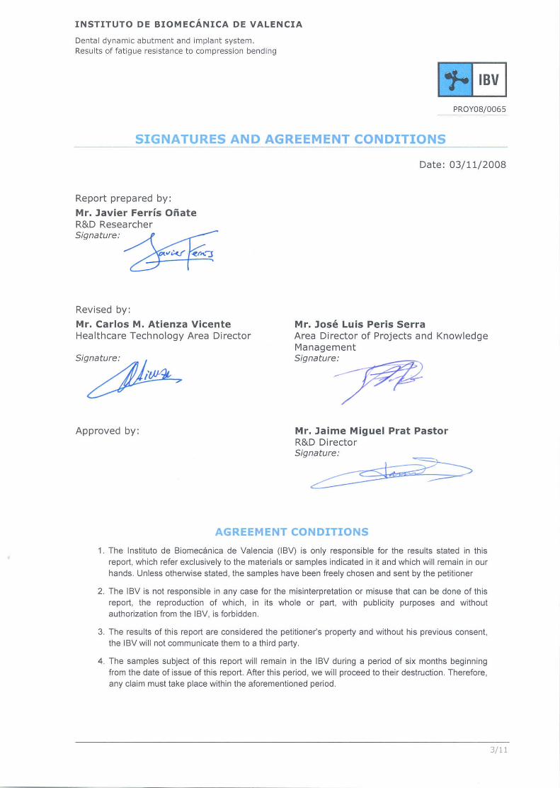
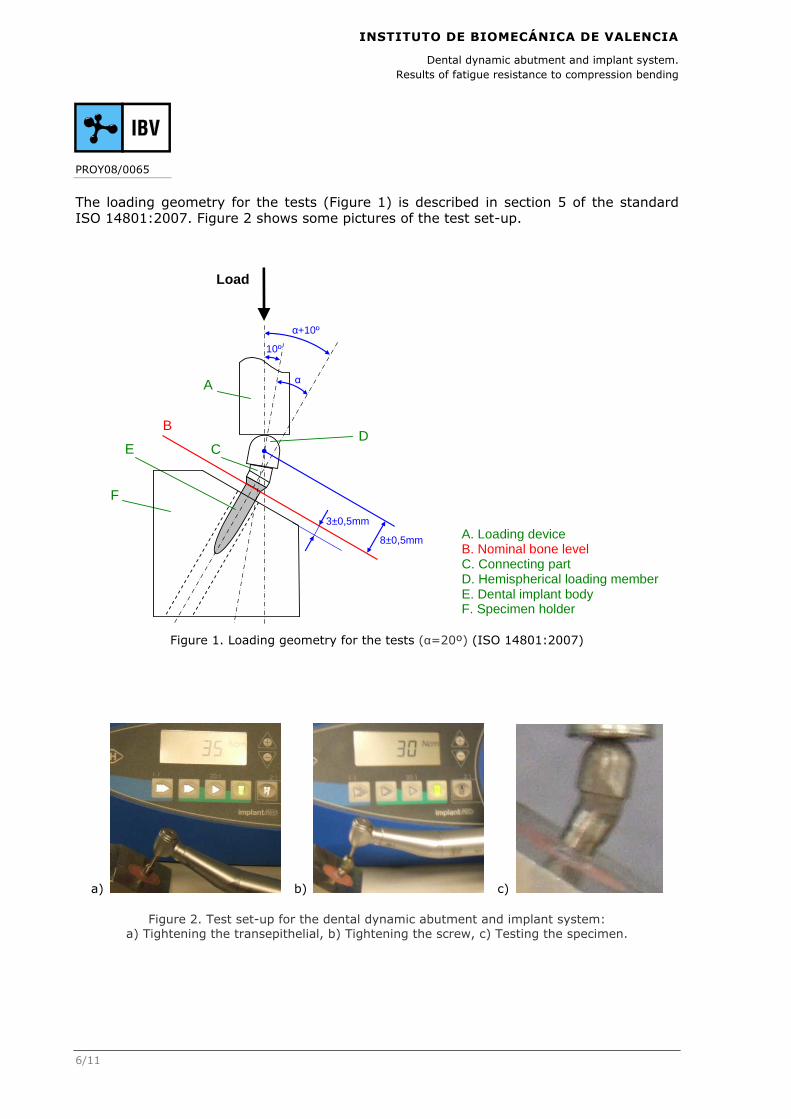
The loading geometry for the tests (Figure 1) is described in section 5 of the standard ISO 14801:2007. Figure 2 shows some pictures of the test set-up.
Figure 1. Loading geometry for the tests (α=20º) (ISO 14801:2007)
a) b) c)
Figure 2. Test set-up for the dental dynamic abutment and implant system: a) Tightening the transepithelial, b) Tightening the screw, c) Testing the specimen.
Load
10º
8±0,5mm
A
B
C D
E
F
3±0,5mm
α
α+10º
A. Loading device B. Nominal bone level C. Connecting part D. Hemispherical loading member E. Dental implant body F. Specimen holder
INSTITUTO DE BIOMECÁNICA DE VALENCIA
Dental dynamic abutment and implant system. Results of fatigue resistance to compression bending
PROY08/0065
7/11
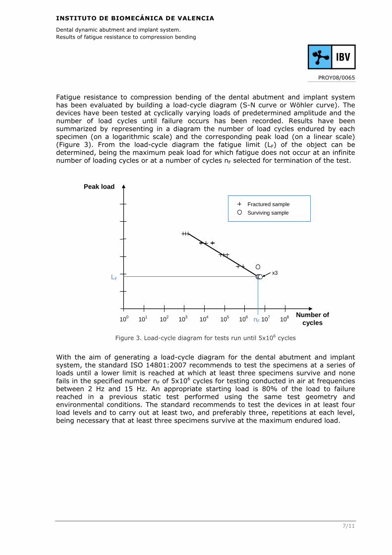
Fatigue resistance to compression bending of the dental abutment and implant system has been evaluated by building a load-cycle diagram (S-N curve or Wöhler curve). The devices have been tested at cyclically varying loads of predetermined amplitude and the number of load cycles until failure occurs has been recorded. Results have been summarized by representing in a diagram the number of load cycles endured by each specimen (on a logarithmic scale) and the corresponding peak load (on a linear scale) (Figure 3). From the load-cycle diagram the fatigue limit (LF) of the object can be determined, being the maximum peak load for which fatigue does not occur at an infinite number of loading cycles or at a number of cycles nF selected for termination of the test.
Figure 3. Load-cycle diagram for tests run until 5x10⁶ cycles
With the aim of generating a load-cycle diagram for the dental abutment and implant system, the standard ISO 14801:2007 recommends to test the specimens at a series of loads until a lower limit is reached at which at least three specimens survive and none fails in the specified number nF of 5x10⁶ cycles for testing conducted in air at frequencies between 2 Hz and 15 Hz. An appropriate starting load is 80% of the load to failure reached in a previous static test performed using the same test geometry and environmental conditions. The standard recommends to test the devices in at least four load levels and to carry out at least two, and preferably three, repetitions at each level, being necessary that at least three specimens survive at the maximum endured load.
Peak load
Number of cycles 106 101 102 103 104 105 100 107 108
x3
nF
LF
Fractured sample
Surviving sample

INSTITUTO DE BIOMECÁNICA DE VALENCIA
Dental dynamic abutment and implant system. Results of fatigue resistance to compression bending
PROY08/0065
8/11
3. RESULTS
Table 2 presents the results of static tests of the dental abutment and implant system which were carried out previously to the fatigue tests and with the same test geometry and environmental conditions. The values of this table correspond to the mean and standard deviation of the five specimens tested.
System Stiffness (N/mm)
Load at the yield point (N)
Displacement at the yield point
(mm)
Load at the rupture point (N)
Displacement at the rupture point (mm)
Dynamic abutment system
4207 ± 654 1833 ± 528 0,51 ± 0,10 2182 ± 318 0,79 ± 0,13
Table 2. Results of static tests
According to the recommendation of the standard ISO 14801:2007, the starting load level for the fatigue tests of the dental abutment and implant system has been defined as 80% of the load to static failure. Depending on the results obtained for each load level, the following procedure has been followed: if the system has withstood 5x10⁶ cycles at a specified load level then the next level load has been increased, otherwise it has been decreased. The total number of load levels applied has been four, and two specimens have been tested at each level except for the fatigue limit at which three specimens have been tested. Therefore, the total number of specimens tested has been nine.
Table 3 shows in chronological order the testing procedure followed, and Figure 4 presents the resulting load-cycle diagram for the dental dynamic abutment and implant system. Results, as well as mode of failure of the specimens, are described in detail in the ANNEX. From the results obtained it can be concluded that the fatigue limit of the tested system is 436,4 N, at which three specimens have survived.
Load level
Peak load (N) Specimen Number of cycles
1 1091 1 597.059
2 1.325.883
2 763,7 3 727.025
4 768.896
3 436,4
5 5.000.000
6 5.000.000
7 5.000.000
4 1418,3 8 15.194
9 6.486
Table 3. Procedure followed in the fatigue tests of the dental dynamic abutment and implant system

INSTITUTO DE BIOMECÁNICA DE VALENCIA
Dental dynamic abutment and implant system. Results of fatigue resistance to compression bending
PROY08/0065
9/11
Figure 4. Load-cycle diagram for the dental dynamic abutment and implant system
4. ANALYSIS OF RESULTS
Fatigue limit of the dental dynamic abutment and implant system has been 436,4 N, with the test geometry indicated in the standard ISO 14801:2007.
The tested systems are used in anterior and posterior teeth. Scientific studies about masticatory forces with natural teeth in several materials have been found, which have observed peak values between 5 and 54 N for incisive and canine teeth (Gay et al., 1994; Dan et al., 2003; Kohyama et al., 2004a, 2004b, 2005; Johnsen et al., 2007; Xu et al., 2008) and peak values between 50 and 284 N for premolar and molar teeth (Morneburg and Pröschel, 2003; Kohyama et al., 2004a, 2004b; Johnsen et al., 2007). The fatigue limit obtained in the performed tests of fatigue resistance widely exceeds these peak load values.
5. CONCLUSIONS
In conclusion it can be stated that the results obtained in the fatigue tests for the dental dynamic abutment and implant system are satisfactory, as the fatigue limit obtained is higher than the usual masticatory forces.
In the fatigue tests, the dental dynamic abutment and implant system has reached a fatigue limit of 436,4 N. The masticatory peak load with incisive and canine teeth ranges from 5 to 54 N and the masticatory peak load with premolar and molar teeth ranges from 50 to 284 N. Therefore, results of the fatigue tests are satisfactory because the fatigue limit obtained is higher than the loads expected during the usual activity of the dental abutment and implant system.
0
200
400
600
800
1000
1200
1400
1600
1000 10000 100000 1000000 10000000
Load
(N)
Nº Cycles
LF
NF
3 points
2 points

INSTITUTO DE BIOMECÁNICA DE VALENCIA
Dental dynamic abutment and implant system. Results of fatigue resistance to compression bending
PROY08/0065
10/11
6. REFERENCES
� DAN H, WATANABE H, KOHYAMA K. Effect of sample thickness on the bite force for apples. Journal of Texture Studies 2003; 34; 287-302.
� GAY T, RENDELL J, MAJOUREAU A, MALONEY FT. Estimating human incisal bite forces from the electromyogram/bite-force function. Archives of Oral Biology 1994; 39(2); 111-115.
� ISO 14801:2007. Dentistry – Implants – Dynamic fatigue test for endosseous dental implants.
� JOHNSEN SE, SVENSSON KG, TRULSSON M. Forces applied by anterior and posterior teeth and roles of periodontal afferents during hold-and-split tasks in human subjects. Experimental Brain Research 2007; 178; 126-134.
� KOHYAMA K, HATAKEYAMA E, SASAKI T, AZUMA T, KARITA K. Effect of sample thickness on bite force studied with a multiple-point sheet sensor. Journal of Oral Rehabilitation 2004a; 31; 327-334.
� KOHYAMA K, HATAKEYAMA E, SASAKI T, DAN H, AZUMA T, KARITA K. Effects of sample hardness on human chewing force: a model study using silicone rubber. Archives of Oral Biology 2004b; 49; 805-816.
� KOHYAMA K, HATAKEYAMA E, DAN H, SASAKI T. Effects of sample thickness on bite force for raw carrots and fish gels. Journal of Texture Studies 2005; 36; 157-173.
� MORNEBURG TR, PRÖSCHEL PA. In vivo forces on implants influenced by occlusal scheme and food consistency. The International Journal of Prosthodontics 2003; 16(5); 481-486.
� XU X, WRIGHT PS, HECTOR MP, HEATH MR, FERMAN AM. Force, rate and work used during incisor penetration on different textural foods. Journal of Texture Studies 2008; 39; 115-128.

INSTITUTO DE BIOMECÁNICA DE VALENCIA
Dental dynamic abutment and implant system. Results of fatigue resistance to compression bending
PROY08/0065
11/11
ANNEX
REPORT. Dental implants. Evaluation of fatigue resistance to compression bending

... ... ... ... ... ... ... RRR EEE PPP OOO RRR TTT
DENTAL IMPLANTS. EVALUATION OF FATIGUE RESISTANCE TO COMPRESSION BENDING
Direct to: TALLADIUM ESPAÑA, S.L.
Prepared by: INSTITUTO DE BIOMECÁNICA DE VALENCIA
Universidad Politécnica de Valencia � Edificio 9C
Camino de Vera s/n � E-46022 � VALENCIA (ESPAÑA)
Tel.: 96 387 91 60. Fax: 96 387 91 69
[email protected] – WWW.IBV.ORG
OCTOBER 2008


IBV-ENSAYOS
DENTAL IMPLANTS. EVALUATION OF FATIGUE RESISTANCE TO COMPRESSION BENDING
080250 - PROY08/0065_4
3/7
C o n t e n t s
SIGNATURES AND AGREEMENT CONDITIONS
1. INTRODUCTION AND OBJECTIVES
2. MATERIAL AND METHODS
3. RESULTS

IBV-ENSAYOS
DENTAL IMPLANTS. EVALUATION OF FATIGUE RESISTANCE TO COMPRESSION BENDING
080250 - PROY08/0065_4
4/7
1. INTRODUCTION AND OBJECTIVES
The objective of this test is to evaluate the fatigue resistance to compression bending of a dental dynamic abutment and implant system.
The tests have been requested by the company TALLADIUM ESPAÑA, S.L., sited in: Avda. de Madrid, 17 - Altillo 1ª. 25002- Lleida (SPAIN).
2. MATERIAL AND METHODS
The test sample and its codification appear in the following table:
CODE DESCRIPTION UNITS
MU08-0742
Dynamic abutment systems formed by: one dynamic abutment of
internal connection D4.8 (PDINT), one screw (TPDSYN), one
transepithelial for Replace internal connection D4.3 (EBRPL43) and
one dental implant Replace Select Tapered TiUnite RP D4.3xL13 from
Nobel Biocare (29414).
9
The test samples will be given back to the client after the tests.
The tests have been performed using an INSTRON 8872-8874 universal testing device.
The tests have been done from 22nd September 2008 to 21st October 2008, with an ambient temperature of 20-23ºC and humidity of 45-64%.
For the test, the implant is inserted between the actuators of the testing machine and cyclically varying compression loads are applied as shown in the following picture.
Load
10º
8±0,5mm
A
B
C D
E
F
3±0,5mm
α
α+10º
A. Loading device B. Nominal bone level C. Connecting part D. Hemispherical loading member E. Dental implant body F. Specimen holder

IBV-ENSAYOS
DENTAL IMPLANTS. EVALUATION OF FATIGUE RESISTANCE TO COMPRESSION BENDING
080250 - PROY08/0065_4
5/7
The conditions of test for each sample have been:
− The cyclically varying compression loads have been applied as a haversine with the values of amplitude, preload, peak load and order indicated in the table.
PEAK LOAD (N) AMPLITUDE (N) PRELOAD (N) ORDER
1418,3 1276,5 141,8 4
1091,0 981,9 109,1 1
763,7 687,3 76,4 2
436,4 392,8 43,6 3
− The loading frequency has been 7 Hz.
− The test has been finished, for each load value, when the specimen failure has occurred or when the sample has reached 5x10⁶ cycles with no failures.
IBV-ENSAYOS
DENTAL IMPLANTS. EVALUATION OF FATIGUE RESISTANCE TO COMPRESSION BENDING
080250 - PROY08/0065_4
6/7
3. RESULTS
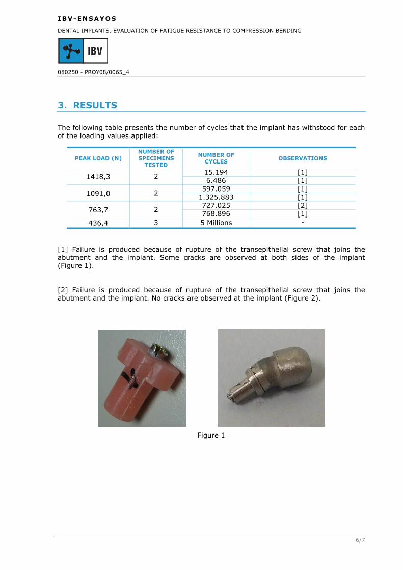
The following table presents the number of cycles that the implant has withstood for each of the loading values applied:
PEAK LOAD (N) NUMBER OF SPECIMENS
TESTED
NUMBER OF CYCLES OBSERVATIONS
1418,3 2 15.194 [1] 6.486 [1]
1091,0 2 597.059 [1]
1.325.883 [1]
763,7 2 727.025 [2] 768.896 [1]
436,4 3 5 Millions -
[1] Failure is produced because of rupture of the transepithelial screw that joins the abutment and the implant. Some cracks are observed at both sides of the implant (Figure 1).
[2] Failure is produced because of rupture of the transepithelial screw that joins the abutment and the implant. No cracks are observed at the implant (Figure 2).
Figure 1

IBV-ENSAYOS
DENTAL IMPLANTS. EVALUATION OF FATIGUE RESISTANCE TO COMPRESSION BENDING
080250 - PROY08/0065_4
7/7
Figure 2
Next, the load-cycle diagram is included:
0
200
400
600
800
1000
1200
1400
1600
1000 10000 100000 1000000 10000000
Load
(N)
Nº Cycles
LF
NF
3 points
2 points
LF: Fatigue limit NF: Number of cycles resulting in no failure