DenCity: A methodology to design cost-optimal zero-energy ...
216
University of Liège Faculty of Applied Science Urban and Environmental Engineering Dept. DenCity: A methodology to design cost-optimal zero-energy lightweight construction for roof stacking Thesis submitted in partial fulfillment of the requirements for the degree of Doctor of Philosophy in Engineering and Technology Sciences Mohamed Amer November 2019
Transcript of DenCity: A methodology to design cost-optimal zero-energy ...

University of Liège
Faculty of Applied Science
Urban and Environmental Engineering Dept.
DenCity: A methodology to design
cost-optimal zero-energy lightweight
construction for roof stacking
Thesis submitted in partial fulfillment of the requirements for the degree of Doctor of Philosophy in
Engineering and Technology Sciences
Mohamed Amer
November 2019

ISBN 978-2-930772-28-8
© 2019 University of Liège
All rights received. No part of the publication may be reproduced in any form by print,
photo print, microfilm, electronic or any other means without written permission from
the publisher.

Promoter: Prof. Shady ATTIA (University of Liège)
Examination Committee
Prof. Jean-Marc Franssen (University of Liège)
Prof. Sigrid Reiter (University of Liège)
Prof. Niels De Temmerman (Vrije Universiteit Brussel)
Prof. Karen Allacker (Katholieke Universiteit Leuven)
Prof. Pieter de Wilde (Plymouth University)
Thesis submitted in partial fulfillment of the requirements for the degree of Doctor of
Philosophy in Engineering and Technology Sciences by
Mohamed Amer Mohamed Mahmoud
November 2019

Abstract
i
Abstract
Roof stacking is considered to be a sustainable approach towards urban densification
and a feasible mean to overcome the challenge of accommodating increasing
populations in cities. However, roof stacking is associated with several challenges that
differs from those of conventional or “stick” buildings. Unfortunately, until now, roof
stacking has not been given a significant importance as a research topic within the
scientific communities. Accordingly, this research aims to provide a leadership to support
the decision making on roof stacking construction on multiple levels, and to accelerate
the transformation towards cost-effective and zero-energy housing in Europe. In order
to achieve this aim, this research is characterized by addressing the topic of roof stacking
from a universal, yet well oriented perspective.
First a methodology has been established to facilitate the decision making on urban
densification through roof stacking. The methodology adopts a systematic approach on
three consecutive levels: urban, engineering, and social. A conceptual framework of a
multidisciplinary decision making for selecting off-site prefabricated constructional
system for roof stacking has been developed. This section includes a classification for
roof stacking construction methods based on an exhaustive investigation of more than
136 roof stacking projects built during the last 20 years. Afterwards, a list of 37
sustainable criteria, on which the decision making on roof stacking takes place, have
been identified based on sustainability triple bottom line, i.e. environmental, economic,
and social.
Finally, this research ends by developing a methodology that supports the decision
making process on cost-optimal zero energy building, by the means of a novel approach,
namely Multi-Objective Parametric Analysis (MOPA), rather than optimization
algorithms. This methodology is composed of three consecutive steps: modeling setup,
parametric simulation, and ends up with evaluation and selection. The aim of dividing
the decisions-making process through several steps is to provide transparency and
repeatability to the developed methodology. This process aligns with the common
practices in the design process, while providing robust and reliable results. As a results,
this thesis provides a multi-scale methodologies for the decision-making process on roof
stacking construction.

ii

Acknowledgement
iii
Acknowledgment
First, I would like to express my deepest appreciation to my promoter and supervisor,
Prof. Shady Attia, for his endless motivation and enthusiasm throughout the last 4 years.
Without his guidance and persistent help this dissertation would not have been possible.
I would also like to thank the PhD committee members, Prof. Sigrid Reiter for her support
and thoughtful discussions, Prof. Jean-Marc Franssen for his constructive feedback,
Prof. Pieter De Wilde for his insightful comments, Prof. Niels De Temmerman and Prof.
Karen Allacker.
I also extend my thanks to Prof. Mohamed Hamdy, who hosted me at the NTNU in
Trondheim, Norway. Thanks for the great discussions and inspirations.
My sincere thanks goes to Géraldine Bosly, for her time, effort and help in finding the
case study on which this research has been applied.
I would like to thank the support from my colleagues and friends. I would like to thank
Ahmed Mustafa, Mohamed El Boujjoufi, Guirec Ruellan, Waqas Mahar, Hamza
Bashandi, Samir Semahi, Constance Uyttebrouck, Dominik Boemer, and many others I
cannot include all their names here. Your friendship had a great contribution to my
success and made it easier to go through hard days.
My continuous gratitude goes to my director Salma Lasri and colleagues at RenoWatt,
who paved the way for this research to develop and help providing energy renovation
for existing public buildings.
Above all, I am grateful to my parents and family for their unconditional support and love.
The credit goes back to them for who I am, and everything I have achieved.
Last but not the least, no words can express my gratitude to my wife, Dr. Sanae Ahayan,
the love of my life, and the reason I kept moving forward. Thank you for your endless
support, unconditional love and for being in my life.
Thanks to everyone who takes the time to read this thesis. I will be glad to discuss its
content with you.

iv

Acronyms
v
Acronyms
BIM Building Information Modeling BPO Building Performance Optimization BPS Building Performance Simulation CG Center of Gravity COP Coefficient of Performance CV (RMSE)
Coefficient of Variation of the Root Mean Square Error
DHW Domestic Hot Water DMF Decision Making Factor dLCC difference in Life Cycle Costing EBPD Energy Performance of Buildings Directive EPS Expanded Polystyrene Foam EU European Union GA Genetic Algorithm GC Global Cost HVAC Heating ventilation and Air Conditioning IEA International Energy Agency LCC Life Cycle Costing MBE Mean Bias Error MEP Mechanical, Electrical, and Plumbing MOPA Multi-Objective Parametric Analysis MW Mineral Wool nZEB nearly Zero Energy Buildings OSB Oriented Strand Board PEC Primary Energy Consumption PPMOF Prefabrication, Preassembly, Modularization and Offsite Fabrication PV Photovoltaic panels RB Reference Building RS Roof Stacking SI Severity Index TFA Treated Floor Area TMY Typical Metrological Year U-value heat-transfer coefficient [W/m2 K] WF Wood Fiber WWR Window to Wall Ratio

vi

Table of contents
vii
Table of Contents
Abstract ........................................................................................................................................................ i
Acknowledgment ........................................................................................................................................ iii
Acronyms ..................................................................................................................................................... v
Table of Contents ...................................................................................................................................... vii
1. Chapter One: Introduction ...................................................................................................................1
1.1. Roof stacking and urban densification ........................................................................................3
1.2. Roof stacking design challenges ..................................................................................................5
1.3. Cost-optimal zero-energy and lightweight for roof stacking ................................................... 12
1.4. Research problems ................................................................................................................... 14
1.6. Research aim and objectives .................................................................................................... 15
1.7. Thesis outline ........................................................................................................................... 15
1.8. Research scope ......................................................................................................................... 16
1.9. List of publications.................................................................................................................... 17
Peer-reviewed journal article ....................................................................................................... 17
2. Chapter Two: Determining the potential of urban densification through roof stacking..................... 19
2.1. Introduction .............................................................................................................................. 21
2.2. Literature review ...................................................................................................................... 22
2.3. Methodology ............................................................................................................................ 30
2.4. Case study ................................................................................................................................ 34
2.5. Outcomes ................................................................................................................................. 48
2.6. Discussion ................................................................................................................................. 54
3. Chapter Three: conceptual framework for off-site roof stacking construction .................................. 55
3.1. Introduction .............................................................................................................................. 57
3.2. Literature review ...................................................................................................................... 58
3.3. Research methods .................................................................................................................... 62
3.4. Projects review and classification ............................................................................................ 63
3.5. Roof stacking conceptual framework development ................................................................ 73
3.6. Discussion ................................................................................................................................. 81
4. Chapter Four: Identification of factors affecting the decision-making on roof stacking construction
83
4.1. Introduction .............................................................................................................................. 85
4.2. Methodology ............................................................................................................................ 86
4.3. Identification of Decision-Making Factors (DMF) .................................................................... 88
4.4. Questionnaire design and surveying ........................................................................................ 92
4.5. Results ...................................................................................................................................... 94
viii
4.6. Discussion ............................................................................................................................... 107
5. Chapter Five: A methodology for multi-objective parametric analysis (MOPA) ............................. 111
5.1. Introduction ............................................................................................................................ 113
5.2. Methodology .......................................................................................................................... 116
5.3. Tools workflow using ‘Grasshopper’ parametric graphical user interface............................. 119
5.4. Design objectives .................................................................................................................... 120
5.5. Discussion ............................................................................................................................... 124
6. Chapter Six: Application for cost-optimal zero-energy lightweight construction measures ............ 125
6.1. Case Study .............................................................................................................................. 127
6.2. Multi-Objective Parametric Analysis (MOPA) ........................................................................ 138
6.3. Discussion ............................................................................................................................... 145
7. Chapter Seven: Conclusion ............................................................................................................ 149
7.1. Summary of the main findings ............................................................................................... 151
7.2. Innovations and limitations of the thesis ............................................................................... 154
7.3. Recommendation for further research .................................................................................. 158
References ............................................................................................................................................. 163
Annex ...................................................................................................................................................... 177
Glossary .................................................................................................................................................. 203

Chapter 1: Introduction
1
1. Chapter One: Introduction
The need to accommodate increasing populations in European cities is substantial. To
address this problem, roof stacking is proposed as an efficient solution towards
achieving sustainable urban densification. We define roof stacking as an added structure
over the rooftop of an existing building to create one or more stories of living spaces.
The first part of this thesis discusses the potential of existing cities on accommodating
increasing population and the criteria on which building engineers follow to build on the
rooftops of existing buildings. The second part of this thesis introduces a new
methodology based on multi-objective parametric analysis. Based on this methodology,
it is possible to aid the decision-making on achieving cost-optimal zero-energy and
lightweight construction for roof stacking.

2

Chapter 1: Introduction
3
1.1. Roof stacking and urban densification
Local and global migration, polarization of intellectuals either skilled labors and
international students, are all factors that contribute to an inevitable increase of
population and higher demand for housing especially in European cities (Bonifazi et al.,
2008). Followed by the global increase in population and economic growth, globalization
and European integration, land price and inner city problems, a phenomenon which is
called urban sprawl has appeared (Vasili, 2013). Urban sprawl is the tendency of
increasing urban growth with low densities in a scattered way through countryside and
urban fringe (EEA, 2006). (Marshall, 2007) reported that urban growth increases with a
frequency equivalent and sometimes higher that population growth rate, given the fact
that 75% of the European population live in urban areas and expected to increase to
80% by 2020, while in seven European counties alone will have 90% of their population
living in urban areas. Thus, urban sprawl is considered as one of the major challenges
that faces urban Europe nowadays that seriously undermines efforts done to meet the
global challenge of climate change (EEA, 2006). Urban sprawl has major impacts that
are evident in the increasing consumption of energy, in addition to land and soil (Attia
and De Herde, 2010). Urban sprawl threatens the natural and rural environment of
Europe, which contributes to the loss of farmlands, carbon emissions increase and side
effects on the local climate of the region (Angel et al., 2016; Seto et al., 2011).

4
Figure 1-1: Urban morphological zones. Edited by Authors. Source: (EEA, 2011)
The rectangle shown in Figure 1.1 refers to the axis known as the European Megalopolis,
which runs from London and Birmingham in the UK passing by Paris and Lille in northern
France, Belgium, Netherlands, Dusseldorf, Cologne and Bonn in Germany till it reaches
northern Italy at Milan and Turin (EEA, 2011).
New research agendas address this issue in response to the upcoming needs to
accommodate increasing population while maintaining sustainable urban development
and limiting urban sprawl (United Nations, 2017a). Many researchers explored the
implications of urban densification, which states that higher city densities support
efficient infrastructure and reduces carbon emissions (Dieleman and Wegener, 2004;
Gaitani et al., 2014; Nabielek, 2011; NRC, 2009; Skovbro, 2001). Others argue that
compact forms significantly reduce the energy consumption on the building and
transportation scale (Ewing et al., 2008; Madlener and Sunak, 2011; Riera Pérez and
Rey, 2013; Steemers, 2003).
There are several methods followed in order to achieve higher densities in cities. Roof
stacking method that has been widely taking place in the last 20 years (Amer et al.,
2018). Roof stacking shows numerous benefits such as conserving vacant areas,
promoting for a balance between urban densification and the preservation of green
areas (Nilsson et al., 2014). Moreover, it was found that applying roof stacking is more
Chapter 1: Introduction
5
energy efficient compared to roof renovation. It was found that roof stacking reduces
energy consumption by 17% more than flat roof renovation and 6% more than saddle
roof renovation (Tichelmann and Groß, 2016). (Marique and Reiter, 2014a) found that
by increasing the density of a neighborhood alone without applying retrofitting measures,
a reduction up to 30% of the energy consumption per m2 could be achieved. Despite the
benefits of roof stacking, there are several drawbacks. (Amer et al., 2017a) presented a
comparative analysis for different densification methods by showing the advantages and
disadvantages of each method, which will be discussed in details in this thesis.
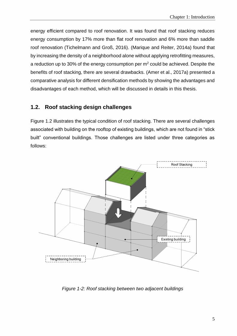
1.2. Roof stacking design challenges
Figure 1.2 illustrates the typical condition of roof stacking. There are several challenges
associated with building on the rooftop of existing buildings, which are not found in “stick
built” conventional buildings. Those challenges are listed under three categories as
follows:
Figure 1-2: Roof stacking between two adjacent buildings

6
Roof stacking construction:
Actual strength of the existing building
The first question that should be asked is whether the existing building is capable of
holding additional structure or not. It is possible to determine the strength of the existing
building either by theoretical calculations or onsite deep investigation. Theoretical
calculation requires possessing the existing building’s technical data, such as buildings
materials’ specifications and the type of soil and foundation. The second method is
applied by investigating the existing structure through multiple techniques used by
specialized civil engineers, such as visual inspections, or destructive investigations.
Those investigations are highly recommended especially for old existing buildings, due
to the natural movements taking place in the soil and within the entire building, which
ends up changing the structural characteristics of the building (e.g. non-shear walls
could ends up bearing weight). Through deep investigation, those types of alteration
could be detected and further internal reinforcements could be applied when needed.
Foundation strength and soil allowable bearing capacity
It is important to know whether the existing building’s foundations could hold more weight
or not, taking in consideration the actual consequences of soil compression throughout
the years. In real cases, the soil surrounding the foundation is dig up to be inspected
together with the foundations, and extra reinforcement is added to the existing
foundations when needed.
Earthquakes and center of gravity
Two main aspects related to earthquakes should be taken in considerations roof
stacking. The first aspect concerns existing building’s center of gravity (CG). As the
height of an existing building increases, its Center of Gravity (CG) gets higher
consequently. It is important to recalculate the structure of the whole building and take
safety factors in consideration. The second aspect is concerned with old building’s
structural configurations. The majority of existing buildings that were built before the First
World War were not designed to resist earthquakes. By adding an additional weight,
existing building becomes more vulnerable to seismic forces.
Chapter 1: Introduction
7
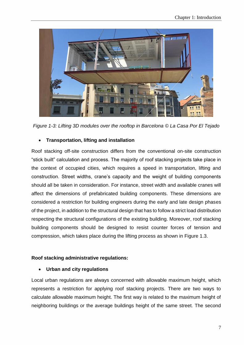
Figure 1-3: Lifting 3D modules over the rooftop in Barcelona © La Casa Por El Tejado
Transportation, lifting and installation
Roof stacking off-site construction differs from the conventional on-site construction
“stick built” calculation and process. The majority of roof stacking projects take place in
the context of occupied cities, which requires a speed in transportation, lifting and
construction. Street widths, crane’s capacity and the weight of building components
should all be taken in consideration. For instance, street width and available cranes will
affect the dimensions of prefabricated building components. These dimensions are
considered a restriction for building engineers during the early and late design phases
of the project, in addition to the structural design that has to follow a strict load distribution
respecting the structural configurations of the existing building. Moreover, roof stacking
building components should be designed to resist counter forces of tension and
compression, which takes place during the lifting process as shown in Figure 1.3.
Roof stacking administrative regulations:
Urban and city regulations
Local urban regulations are always concerned with allowable maximum height, which
represents a restriction for applying roof stacking projects. There are two ways to
calculate allowable maximum height. The first way is related to the maximum height of
neighboring buildings or the average buildings height of the same street. The second

8
way is related to the right to light, which means that the maximum height shouldn’t affect
reduce the amount of daylighting received by neighboring buildings. Even though when
buildings’ strength could bear additional load, they have to comply with urban
regulations. Other restrictions are related to getting approval from the city administration
that is concerned with the conservation of city’s architecture. Other parameters related
to urban environment, social justice and fair distribution of neighborhood densities are
taken in consideration. These parameters aim to maintain sustainable living environment
in terms of open spaces, adequate population, and transportation.
Social acceptance
Social acceptance represents one of the main restrictions when deciding on proposing
interventions in the surrounding urban context in general, and roof stacking in particular.
Social acceptance in this context means the acceptance of building’s owner, living
inhabitants and surrounding neighbors represented by the community associations.
Since that roof stacking may cause noise during construction, inconvenience or general
discomfort to the surrounding neighbors, an approval from the community has to be
granted prior to the construction process. Sometimes neighbors represented in
community associations have to be involved in the design phases and decision-making
process as an active stakeholder.
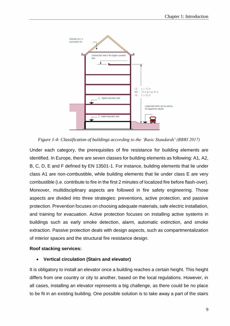
Fire safety
In fire resistance regulations, buildings are categorized based on their height and
function as shown in Figure 1-4:
- Low-rise: height less than 10 meters
- Mid-rise: height between 10 and 25 meters
- High-rise: height more than 25 meters
Chapter 1: Introduction
9
Figure 1-4: Classification of buildings according to the ‘Basic Standards' (BBRI 2017)
Under each category, the prerequisites of fire resistance for building elements are
identified. In Europe, there are seven classes for building elements as following: A1, A2,
B, C, D, E and F defined by EN 13501-1. For instance, building elements that lie under
class A1 are non-combustible, while building elements that lie under class E are very
combustible (i.e. contribute to fire in the first 2 minutes of localized fire before flash-over).
Moreover, multidisciplinary aspects are followed in fire safety engineering. Those
aspects are divided into three strategies: preventions, active protection, and passive
protection. Prevention focuses on choosing adequate materials, safe electric installation,
and training for evacuation. Active protection focuses on installing active systems in
buildings such as early smoke detection, alarm, automatic extinction, and smoke
extraction. Passive protection deals with design aspects, such as compartmentalization
of interior spaces and the structural fire resistance design.
Roof stacking services:
Vertical circulation (Stairs and elevator)
It is obligatory to install an elevator once a building reaches a certain height. This height
differs from one country or city to another, based on the local regulations. However, in
all cases, installing an elevator represents a big challenge, as there could be no place
to be fit in an existing building. One possible solution is to take away a part of the stairs
10
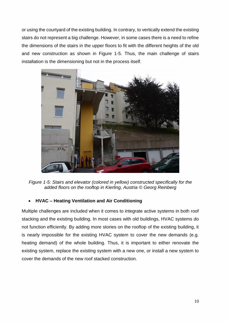
or using the courtyard of the existing building. In contrary, to vertically extend the existing
stairs do not represent a big challenge. However, in some cases there is a need to refine
the dimensions of the stairs in the upper floors to fit with the different heights of the old
and new construction as shown in Figure 1-5. Thus, the main challenge of stairs
installation is the dimensioning but not in the process itself.
Figure 1-5: Stairs and elevator (colored in yellow) constructed specifically for the added floors on the rooftop in Kierling, Austria © Georg Reinberg
HVAC – Heating Ventilation and Air Conditioning
Multiple challenges are included when it comes to integrate active systems in both roof
stacking and the existing building. In most cases with old buildings, HVAC systems do
not function efficiently. By adding more stories on the rooftop of the existing building, it
is nearly impossible for the existing HVAC system to cover the new demands (e.g.
heating demand) of the whole building. Thus, it is important to either renovate the
existing system, replace the existing system with a new one, or install a new system to
cover the demands of the new roof stacked construction.
Chapter 1: Introduction
11
Water, plumbing & electricity
There is a minor challenge associated with integrating or adding extensions to water,
plumbing and electricity. However, it has to be taken in consideration within the design
phase to apply modifications or additions when needed.
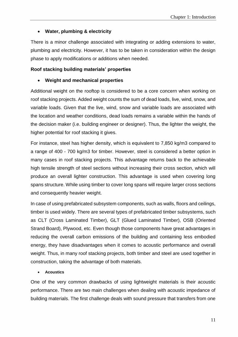
Roof stacking building materials’ properties
Weight and mechanical properties
Additional weight on the rooftop is considered to be a core concern when working on
roof stacking projects. Added weight counts the sum of dead loads, live, wind, snow, and
variable loads. Given that the live, wind, snow and variable loads are associated with
the location and weather conditions, dead loads remains a variable within the hands of
the decision maker (i.e. building engineer or designer). Thus, the lighter the weight, the
higher potential for roof stacking it gives.
For instance, steel has higher density, which is equivalent to 7,850 kg/m3 compared to
a range of 400 - 700 kg/m3 for timber. However, steel is considered a better option in
many cases in roof stacking projects. This advantage returns back to the achievable
high tensile strength of steel sections without increasing their cross section, which will
produce an overall lighter construction. This advantage is used when covering long
spans structure. While using timber to cover long spans will require larger cross sections
and consequently heavier weight.
In case of using prefabricated subsystem components, such as walls, floors and ceilings,
timber is used widely. There are several types of prefabricated timber subsystems, such
as CLT (Cross Laminated Timber), GLT (Glued Laminated Timber), OSB (Oriented
Strand Board), Plywood, etc. Even though those components have great advantages in
reducing the overall carbon emissions of the building and containing less embodied
energy, they have disadvantages when it comes to acoustic performance and overall
weight. Thus, in many roof stacking projects, both timber and steel are used together in
construction, taking the advantage of both materials.
Acoustics
One of the very common drawbacks of using lightweight materials is their acoustic
performance. There are two main challenges when dealing with acoustic impedance of
building materials. The first challenge deals with sound pressure that transfers from one

12
space to another. This occur most commonly on a horizontal level between internal
rooms together, and internal room with the exterior. Thus, there are several steps to
optimize the performance of sound impedance of lightweight building materials.
- Creating double layer wall
- Separate both layers with sound insulation
- Increases the cavity between two layers
- Reduce sound bridges formed by studs connecting both layers
The second challenge occurs on a vertical level. This challenge takes place when
building one or more floors over the rooftop using lightweight materials. Therefore,
materials used to construct ceilings and floors should be treated differently from those
used for walls. When considering another building material such as concrete, it has
better acoustic impedance; however it is associated with much heavier weight. Thus, the
choice of building materials is required during the early stages of roof stacking design
considering multi-objective approach.
Thermal performance
Two main concerns are associated with the thermal performance of lightweight building materials: thermal
resistance and thermal mass. Thermal resistance is the tendency of the material to resist heat transfer
from one side to another through conduction. Lightweight building materials such as timber and steel have
poor thermal resistance values. For example plywood with a thickness of 90 mm has R value equivalent
to 1.0 m2K/W compared to insulation materials such as rock wool with the same thickness which is
equivalent to 4.09 m2K/W. Therefore, using insulation materials is inevitable when designing wall sections
for R.S. buildings.
The second concern is related to thermal mass, which is the ability of a material to absorb and store heat.
Thermal mass is essential in regulating temperature between the indoor and outdoor during day and night.
This problem may cause overheating risk during summer in hot and moderate climates. Passive solutions,
such as automated shading devices, high thermal mass and reflective rendering materials, etc., could be
used to reduce but not eliminating that risk. Therefore, highly efficient HVAC system is essential to prevent
overheating risks and secure indoor constant thermal comfort during the whole year.
1.3. Cost-optimal zero-energy and lightweight for roof stacking
According to the latest studies by the International Energy Agency (IEA), it was found
that building sector accounts for 36% of carbon emissions, 40% of the energy demand
in the European Union (Khatib, 2012), in addition to the need for housing and

Chapter 1: Introduction
13
construction, which is estimated to increase by 32% in 2050 (United Nations, 2015).
Thus, several international and European calls have emerged to apply stricter
regulations on the building industry to achieve net zero-energy buildings (nZEBs) by
2020, and reduce the overall carbon emission of the buildings (Hu, 2019; Knoop and
Lechtenböhmer, 2017; Piderit et al., 2019; Shim et al., 2018). However, cost-optimality
of buildings should be considered when opting for high energy performance buildings.
Thus, in order to achieve cost-optimal and energy efficient buildings, the Energy
Performance in Buildings Directive EBPD-recast in 2010 (European Commission, 2010)
requests the European Union (EU) Member States to ensure achieving cost-efficient
optimal level when designing for minimum energy consumption for buildings. The same
request goes for nZEBs, which should be feasible for implementation. The fact is,
achieving this target is a difficult task, as it requires exploring a huge number of design
solutions resulting from exploring a different number of design variables. Therefore, and
in alignment with EPBD requirements, it has been of great interest from the scientific
community and industry to study and promote cost-optimal and energy efficient
buildings.
Since the characteristics of the building envelope highly affect the overall energy
performance of residential buildings in all scales, achieving zero-energy buildings
requires using thick walls and insulations, which is accompanied in most cases with
additional weight in construction (Attia, 2018a). This represents a conflict in the design
objectives when opting for lightweight construction. The choice of lightweight
construction has been put forward as an objective based on a wide survey conducted
among building engineers who have expertise in building on rooftops around Europe
(Amer and Attia, 2019a).

14
1.4. Research problems
Roof stacking as a definition and field of research has not been studied thoroughly,
despite the increasing number of roof stacking projects in European cities. As a results
of the lack of research in this topic, there are several evident research gaps as listed
below:
- Given that roof stacking practices are highly based on off-site construction methods
and prefabrication on its multiple levels, there is a significant lack of integrating off-
site construction and prefabrication research with roof stacking.
- A lack of appropriate identification and classification of the existing off-site
construction methods and building materials that are specifically used for roof
stacking.
- A lack of a guiding framework to select roof stacking construction methods
- Relevant studies that identify decision making factors for roof stacking in the
European context.
- A lack of knowledge on the design, construction and operation of zero energy
lightweight constructions for urban densification.
- A simplified decision-making method, in terms of complexity of the calculation process
and required tools, to identify cost-optimal zero-energy and lightweight roof stacking
design.
1.5. Research questions
Accordingly, there are four main questions raised in this research project, which are
listed as follows:
(1) What is the potential of existing cities to accommodate increasing population by
roof stacking?
(2) Which methods are used for roof stacking design?
(3) Which criteria are involved when building on rooftops?
(4) How to achieve cost-optimal zero-energy and lightweight roof stacking
construction?
Chapter 1: Introduction
15
1.6. Research aim and objectives
The aim of this research is to increase urban density through expanding cost-effective
and zero-energy housing. Thus aligning with EU agendas aiming to achieve sustainable
built environment, on the urban and building scale, through informed multi-disciplinary
multi-objective decision making on roof stacking construction. The extended research
objectives incorporate the following:
(1) Provide an integrative approach for decision making on urban densification through
roof stacking, based on urban, engineering, and architectural levels.
(2) Develop a framework to support the multidisciplinary decision making for selecting
off-site constructional system for roof stacking.
(3) Identify decision making criteria for selecting roof stacking construction method and
rank the importance of each criterion from the perspective of building engineers..
(4) Develop a simplified methodology based on parametric analysis to achieve
multiple-objective design targets.
1.7. Thesis outline
This thesis consists of 4 core chapters in addition to an introduction and conclusion
chapters. A discussion section is added after each core chapter, thus there is no
discussion chapter in this thesis. Due to the lack of relevant studies on roof stacking, this
research handles this topic from different scales (i.e. urban and building scale), as
illustrated in Figure 1-6.
In part I, the potential of roof stacking is illustrated on the city level and criteria on which
the decision-making on roof stacking construction are identified. In part II, a methodology
for cost-optimal zero-energy lightweight construction is developed. The thesis is made
up of a series of articles that have been published, or under review to peer-reviewed
journals. For this reason some overlap may occur between the various chapters.
The introduction, scope and outline of this thesis are presented in Chapter 1. Afterwards,
urban densification maps through roof stacking are generated for the city of Brussels in
Chapter 2, followed by a classification and multi-disciplinary framework development to
select roof stacking construction method in Chapter 3. The criteria of choosing the roof

16
stacking method by building engineers are identified and ranked in Chapter 4. Chapter
5 presents the developed methodology followed by Chapter 6 where the application of
the methodology on a case study is carried out. Finally, chapter 7 presents the
conclusion of this thesis.
Figure 1-6: Thesis Outline
1.8. Research scope
As shown previously in sections 1.2 and 1.3, there are several factors and aspects
involved when considering building on the rooftop of existing buildings. However, it is
never possible to include all aspects within a limited time and effort of a PhD research
work. Therefore, a holistic portrayal of settings dominated by qualitative research
methods is presented through the developed decision-making frameworks considering
several aspect associated with roof stacking, such as the constructional aspects,
administrative regulations, services, and building materials properties. However, it is out
of the scope of this research to quantify their effect in the decision-making process, it is
rather aimed to have those aspects well defined and taken in consideration.
Afterwards, quantitative research methods based on numerical simulations for precise
and well defined design objectives have been employed. The scope of the developed

Chapter 1: Introduction
17
decision-making methodology focuses on each of (1) the cost, in terms of life cycle
costing, (2) energy efficiency, in terms of zero-energy design target, and (3) the added
construction weight, in terms of dead load, of roof stacking.
1.9. List of publications
Chapter 1 is based on:
1. Amer, M., Attia, S., 2017. ROOF STACKING: Learned Lessons from Architects.
SBD Lab, Liege University, Belgium.
Peer-reviewed journal articles
Chapter 2 is based on:
2. Amer, M., Mustafa, A., Teller, J., Attia, S., Reiter, S., 2017b. A methodology to
determine the potential of urban densification through roof stacking. Sustain.
Cities Soc. 35, 677–691. https://doi.org/10.1016/j.scs.2017.09.021
Chapter 3 is based on:
3. Amer, M., Mustafa, A., Attia, S., 2019. Conceptual framework for offsite roof
stacking construction. Journal of Building Engineering. 26, 100873.
https://doi.org/10.1016/j.jobe.2019. 100873
Chapter 4 is based on:
4. Amer, M., Attia, S., 2019. Identification of sustainable criteria for decision-
making on roof stacking construction method. Sustain. Cities Soc. 47, 101456.
https://doi.org/10.1016/j.scs.2019.101456
Chapter 5 and 6 are based on:
5. Amer, M., Hamdy, M., Mustafa, A., Wortmann, T., Attia, S., 2020. Methodology
for design decision support of cost-optimal zero-energy lightweight construction.
Energy and Buildings, 223, 110170.
https://doi.org/10.1016/j.enbuild.2020.110170

18
Refereed Conference Proceedings
6. Amer, M., Mahar, WA., Reullan, G., Attia, S., 2019. Sensitivity Analysis of Glazing
Parameters and Operational Schedules on Energy Consumption and Life Cycle
Cost. 16th Conference of International Building performance Simulation
Association. Rome, Italy.
7. Amer, M., Attia, S., 2019. A Framework for Cost-Optimal Zero-Energy Lightweight
Construction. Presented at the Symposium on Simulation for Architecture &
Urban Design, SimAUD 2019, Atlanta GA, USA.
8. Amer, M., Attia, S., 2018. Timber construction methods for roof stacking:
Classification and comparative analysis. WTCE, south Korea,
9. Amer, M., Reiter, S., Attia, S., 2018. Urban Densification through Roof Stacking:
Case Study, in: European Network for Housing Research (ENHR) Annual
Conference 2018. Uppsala University, Uppsala, Sweden.
10. Amer, M., Attia, S. A REVIEW ON ROOF STACKING CASE STUDIES FOR
URBAN DENSIFICATION. 34èmes Rencontres Universitaires de Génie Civil de
l'AUGC | 24.05.2016 | Liege, Belgium.
Un-refereed Publications
11. Amer, M., Attia, S. DenCity: Zero Energy Lightweight Construction Households
for Urban Densification. Presented at the 2016 Doctoral Seminar on Sustainability
Research in the Built Environment (DS²BE-2016). Leuven, Belgium
12. Amer, M., Attia, S. DenCity: Zero Energy Lightweight Construction Households
for Urban Densification. Presented at the 2017 Doctoral Seminar on Sustainability
Research in the Built Environment (DS²BE-2017). Liege, Belgium.
13. Amer, M., Attia, S. DenCity: Zero Energy Lightweight Construction Households
for Urban Densification. Presented at the 2018 Doctoral Seminar on Sustainability
Research in the Built Environment (DS²BE-2018). Brussels, Belgium.

Chapter 2: Determining the potential of urban densification through roof stacking
19
2. Chapter Two: Determining the potential of
urban densification through roof stacking1
Facing the need to accommodate a growing number of inhabitants in major European
cities, this research aimed to establish a methodology that facilitates decision making on
urban densification through roof stacking. The methodology adopts a systematic
approach on three consecutive levels: urban, engineering, and social. Multiple criteria
are identified to assess and map the roof stacking potential in terms of location and
number of added floors. The Brussels Capital Region was chosen as a case study to
experiment with the developed workflow chart and validate the proposed approach,
using ArcGIS software, by creating a map of the urban densification potential through
roof stacking of Brussels at the city scale. The results show a realistic potential of
accommodating 30% of the expected population increase in Brussels by the year 2040
using only roof stacking, provided that the current urban regulations are respected. In
addition, a theoretical potential to accommodate more than the expected population
increase by the same year is proposed provided that urban planning regulations are
relaxed in relation to the height of buildings. Further applications to other cities in Europe
would help create additional opportunities to develop an automated tool for estimating
such potentials on a wider scope.
1 This chapter is based on this article: Amer, M., Mustafa, A., Teller, J., Attia, S., & Reiter, S. (2017). A
methodology to determine the potential of urban densification through roof stacking. Sustainable Cities and Society, 35 (Supplement C), 677–691. https://doi.org/10.1016/j.scs.2017.09.021

20
Chapter 2: Determining the potential of urban densification through roof stacking
21
2.1. Introduction
Due to population and economic growth, globalization and European integration, and
land price and inner city problems, rapid urbanization and urban sprawl phenomena
have occurred (EEA, 2006; Vasili, 2013). This has resulted in an increasingly large urban
footprint and higher levels of CO2 emissions. New urban agendas have promoted the
development of urban spatial frameworks. These frameworks adopt an approach toward
sustainable land use management based on appropriate compactness, polycentrism,
and mixed use through infill development or planned extension strategies, which
prevents urban sprawl and marginalization (United Nations, 2017b). Accordingly,
multiple approaches are followed to achieve compactness and urban densification, such
as infill development and roof extensions. This chapter provides a model for decision
support to optimize urban densification through roof stacking, based on a triple analysis
of the built environment at the urban planning, engineering, and architectural levels. In
this chapter, a methodology is developed to assess at different urban scales the primary
potential for urban densification by providing more dwellings through roof stacking. It
sets criteria to measure and map that potential in terms of location and added floors,
providing guidance to urban planners and decision-makers establishing development
programs based on quantified results and values. The significance of this research lies
in the creation of a generic approach that relies on available information from a GIS
database to evaluate and quantify the urban roof stacking potential and that further
assists in the creation of maps that identify such characteristics and represent the
location of that potential. This chapter presents an integrative approach for decision
making pertaining to urban densification through roof stacking, by which each of the
urban, engineering, and architectural aspects is taken into consideration and illustrated
in one workflow chart.
A review of the literature critically covers the evidence behind the choice of
accommodating the growing population of Europe by densifying its major cities or by
extending urban sprawl. Consequently, a method for reaching a reasonable urban
densification through roof stacking is proposed as a sustainable approach toward
housing an increasing population with minimum effects on the environment, while also
taking into account the quality of life in cities. To define this potential for roof stacking, a
set of criteria was identified and a workflow chart that illustrates the entire methodology
and acts as a tool for decision making was developed. Using the city of Brussels as a

22
case study, various maps were generated to visualize the densification potential. This
research targets policy and decision makers at the regional and district levels, as well
as real estate developers and urban planners. The framework presented aids the
decision making process for using roof stacking as an approach toward developing
sustainable urban densification and optimal city compactness.
This chapter is organized into seven main sections. The first section introduces the
research. The second section reviews the expected increase in the population of
Europe, urban sprawl and its consequences on the environment, and regional strategies
for urban containment, in addition to urban densification methods at the city scale and
their advantages and disadvantages. The third section introduces the methodology
established by this research, a workflow chart illustration, and mapping criteria for urban
densification through roof stacking. The fourth section focuses on the application of the
methodology in a case study, by which maps of urban densification potential in the city
of Brussels are generated using the developed workflow chart. The fifth section presents
and analyses the final maps and the results of this application to the Brussels Capital
Region. The sixth section presents a summary of the main findings of this research and
discusses the further usage, strengths, and limitations of the developed tool. The last
section presents the conclusions of the chapter.
2.2. Literature review
Increasing population in Europe
Worldwide, population is expected to increase by 32% by the year 2050, which is
equivalent to an increase of 2.37 billion inhabitants. Even though the fertility rate is lower
in Europe than on other continents, Europe is affected by the global increase of
population and migration dynamics (United Nations, 2015). According to the Intentional
Migration, Integration and Social Cohesion (IMISCOE) network, it has been reported that
an emergence in the global migration market was evident in the last two decades
(Bonifazi et al., 2008; OECD, 2001). When European countries are grouped according
to income rather than geography, countries with higher income receive an average of
4.1 million immigrants annually from lower income EU and non-EU countries. It is
expected that the total net gain of immigrants in high income countries will reach 91
million by 2050 (United Nations, 2015). This migration has multiple consequences for

Chapter 2: Determining the potential of urban densification through roof stacking
23
urban configurations and housing policies. It has been observed that immigrants,
seeking the financial and social opportunities offered by large cities, settle mostly in
urbanized areas (EEA, 2006).
Urban sprawl and containment strategies
As a result of population and economic growth, globalization and European integration,
and land price and inner city problems, an urban sprawl phenomenon has developed
(Vasili, 2013). At present, 75% of the European population lives in urban areas, and the
urban population is expected to increase to 80% by 2020; however, seven European
countries will have 90% of their population living in urban areas by 2020, but a large
portion of these areas are sprawled. The major secondary effects of unplanned urban
sprawl are increasing consumption of energy in both the building and transportation
sectors (Steemers, 2003), loss of land and soil (Attia and De Herde, 2010; EEA, 2006),
which threatens the natural and rural environment of Europe and contributes to the loss
of farmland, increases in carbon emissions and effects on the local climate of the region
(Angel et al., 2016; Seto et al., 2011), and numerous other problems, such as
diminishment of soil infiltration, dependency on cars, and increasing costs of
infrastructure, networks, and services (Marique et al., 2013). Even if some effects related
to high compactness, such as congestion, air pollution, increases of land prices, and
others, are problematic and low-density developments are one of the preferred living
accommodations (Gordon and Richardson, 1997; Howley, 2009), the negative
environmental and economic consequences of urban sprawl prevail. Several
governments in Europe have attempted to limit urban sprawl through manifold integrated
urban growth management strategies, bringing together municipalities, civil society,
business, and economy. At the urban planning level, (Pendall et al., 2002) classified
urban containment strategies into three major types: green belts, urban growth
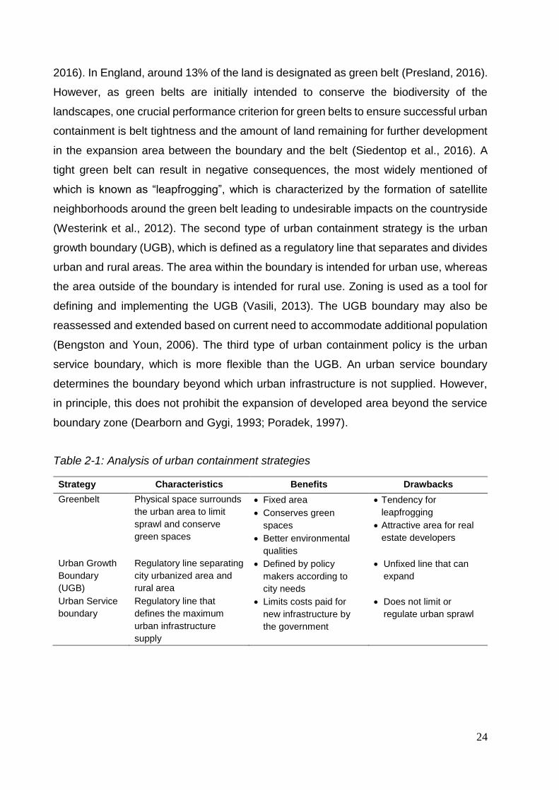
boundaries (UGB), and urban service boundaries, as shown in Table 2.1
The first type of urban containment strategy, the green belt, is defined as continuous
green physical space that surrounds metropolitan regions and urbanized areas (Gennaio
et al., 2009). The goals of establishing green belts are to prevent neighboring towns from
merging with each other, check unrestricted sprawl, safeguard countryside from
encroachment, preserve the special character of historic towns, and assist urban
generation (Presland, 2016). In Germany, approximately 60% of the planning regions
have implemented green belt strategies in their development plants (Siedentop et al.,
24
2016). In England, around 13% of the land is designated as green belt (Presland, 2016).
However, as green belts are initially intended to conserve the biodiversity of the
landscapes, one crucial performance criterion for green belts to ensure successful urban
containment is belt tightness and the amount of land remaining for further development
in the expansion area between the boundary and the belt (Siedentop et al., 2016). A
tight green belt can result in negative consequences, the most widely mentioned of
which is known as “leapfrogging”, which is characterized by the formation of satellite
neighborhoods around the green belt leading to undesirable impacts on the countryside
(Westerink et al., 2012). The second type of urban containment strategy is the urban
growth boundary (UGB), which is defined as a regulatory line that separates and divides
urban and rural areas. The area within the boundary is intended for urban use, whereas
the area outside of the boundary is intended for rural use. Zoning is used as a tool for
defining and implementing the UGB (Vasili, 2013). The UGB boundary may also be
reassessed and extended based on current need to accommodate additional population
(Bengston and Youn, 2006). The third type of urban containment policy is the urban
service boundary, which is more flexible than the UGB. An urban service boundary
determines the boundary beyond which urban infrastructure is not supplied. However,
in principle, this does not prohibit the expansion of developed area beyond the service
boundary zone (Dearborn and Gygi, 1993; Poradek, 1997).
Table 2-1: Analysis of urban containment strategies
Strategy Characteristics Benefits Drawbacks
Greenbelt Physical space surrounds
the urban area to limit
sprawl and conserve
green spaces
Fixed area
Conserves green
spaces
Better environmental
qualities
Tendency for
leapfrogging
Attractive area for real
estate developers
Urban Growth
Boundary
(UGB)
Regulatory line separating
city urbanized area and
rural area
Defined by policy
makers according to
city needs
Unfixed line that can
expand
Urban Service
boundary
Regulatory line that
defines the maximum
urban infrastructure
supply
Limits costs paid for
new infrastructure by
the government
Does not limit or
regulate urban sprawl

Chapter 2: Determining the potential of urban densification through roof stacking
25
In conclusion, each of the urban containment strategies has its own drawbacks, which
usually necessitates a wider framework at the regional and urban level to work
simultaneously on urban densification and containment strategies to ensure best
practices. Reasonable urban densification is a recommended and valid framework to
limit urban sprawl and support containment strategies at the spatial, economic, and
infrastructure levels.
Urban densification methods
Urban densification refers to the approach of compact city planning, which has been
progressively argued since the 1990s and has been considered widely as a global
applied planning concept (Jenks and Colin, 2010; Roo, 2000). Three main
characteristics define a compact city: dense and proximate development patterns, urban
areas linked by transportation, and accessibility to local services (OECD, 2012). Boyko
and Cooper (Boyko and Cooper, 2011) have explored definitions of densification and
methods of measuring the density of cities. They propose an extensive comparison
between densification and sprawl approaches in terms of mobility, land use, social
equity, green spaces, energy, and their physical advantages and disadvantages. Other
research has worked on the question: “where should densification occur?” Marique and
Reiter (2014) claimed that the increase in density of existing neighborhoods should be
focused on the areas that are the best located and equipped with urban services. They
have presented several means of densification as shown in Figure. Densification along
public transportation nodes encourages inhabitants to use fewer private vehicles for
commuting and thus reduces carbon emissions in cities (Schmitt and Reardon, 2012).
In some cases, densification is a solution with higher urgency due to inevitable pressures
such as geographical or geo-political constraints.
Moving toward urban densification intends to provide a solution for accommodating a
population increase in major cities or suburbs, while also counteracting sprawl outside
of the city and encroachment on farmland and green areas. Densification strategies are
usually included in the planning policies of many European cities, with the goal of
approaching sustainable urban development. However, densification may inherit several
problems in land use policies as a consequence of the deviation between theories and
practice. More precisely, many contradictions may occur at different levels, such as the
political, planning, and socioeconomic levels. Urban densification presents several risks,
including increasing air pollution and congestion, modifying the urban morphology and

26
architectural typologies, neglecting urban heritage, creating heat islands and wind
discomfort, reducing daylighting and solar access (Marique and Reiter, 2014c), putting
pressure on urban infrastructure, networks, and services, among others. Moreover,
several researchers have debated the correlation between high urban density and
reduced use of automobiles.
Some research has highlighted the secondary effects of some types of densification on
urban green areas (Byomkesh et al., 2012; Heezik and Adams, 2014; Rafiee et al.,
2009), with the goal of defining challenges to and strategies for flourishing urban green
spaces (Bolleter and Ramalho, 2014; Haaland and van den Bosch, 2015).
filling backyard
infill development
house re-division
building reusing
demolish & rebuild
attic exchange
roof stacking
Figure 2-1: Illustrations for existing urban densification methods
In this research, seven methods of urban densification have been implemented as
shown in Figure 2.1. The listed methods are meant to give an example of different urban
densification methods rather than being inclusive to all existing methods. The first
method is densification by filling the “backyards” of existing buildings, thus creating a
horizontal extension (Marique and Reiter, 2014a). The second method, referred to as
infill development, is the process of closing the gaps and vacant lots between buildings
in the city (Marique and Reiter, 2014c). A good example is the initiative made by the city

Chapter 2: Determining the potential of urban densification through roof stacking
27
of Cologne, called “Baulückenprogramm”, by which 20,000 new dwellings were built by
infill development (Attenberger, 2014; Stadt Köln, 2011). The third method of
densification is demolishing existing low-density buildings and replacing them with
higher–density structures, for example high-rise buildings or compact–frame structures
(Attia, 2015; Burton et al., 2013).
A fourth method of densification is transforming and renovating saddle roofs on the top
of buildings into wider and livable spaces (Floerke et al., 2014; Tichelmann and Groß,
2016). This method has the double benefit of making use of the negligible zone of the
attic and helping to reduce the total energy consumption of the building by enhancing
the quality of the roof and the building’s insulation. A fifth method is densification through
roof stacking, which is the method of concern in this research (Amer et al., 2017a; Attia,
2015). Roof stacking is simply the addition of stories to existing buildings to
accommodate more inhabitants. The capacity for and number of added stories depends
on several factors that will be discussed briefly in the following sections. Table 2.2
provides a summary and comparison of the previously mentioned methods for urban
densification.
A part of the responsibility of local authorities is to define the densification need capacity
and form (Burton et al., 1996; Williams, 1997, 1998) based on the characteristics of each
city (geology, climate, urban morphology, types of buildings, mobility behaviors,
transportation networks, etc.), while avoiding densities that are too high or too low and
respecting both sustainable development and the quality of urban life.
Table 2-2: Analysis of urban densification strategies
Method Characterization Advantages Disadvantages
Filling
Backyards
Creating horizontal
extension,
increasing the
surface area of
existing buildings on
their backyards
(Attia, 2015;
Marique and Reiter,
2014a)
Provide additional
space for the
same property
Opportunity to
improve the
density while
preserving the
urban landscape
Retains the
integrity of
existing dwellings
Seal more surface
Increasing carbon
footprint
Reduce vegetation
surfaces
Increase heat
island effects

28
Infill Establishing new
buildings on vacant
lots and gaps
between buildings or
areas not built-up
previously or built-
up areas with other
purposes (Brunner
and Cozens, 2013;
Marique and Reiter
2014)
Usage of
abandoned areas
and opportunity of
revitalizing these
spaces
Opportunity to
improve the
density while
preserving the
urban landscape
and urban
morphology
Retains the
integrity of
existing dwellings
Occupy spaces
with a vegetation
or recreational
function potential
Increasing carbon
footprint
Occupy spaces
with parking or
collective service
potential
Potential damage
to the nearby
buildings during
construction
process.
Demolish
& rebuild
Applied in areas
with lower density
where houses are
demolished and
replaced with high-
rise buildings or
compact frame
(Burton et al., 2013;
Marique and Reiter
2014)
Higher flexibility to
increasing density
on any certain plot
Opportunity to
apply designs with
higher efficiency
Causes high traffic
for already dense
neighborhoods
when building on
site.
Increases the use
of materials and
construction waste
High cost is
accompanied by
demolition and
new construction
Loss of resources
(i.e. existing
property)
Risk for the urban
heritage
Transformation of
the city skyline
and urban
morphology
Roof
transforma
tion
Transformation of
saddle roofs into a
complete storey with
flat roof and larger
floor area
Does not occupy
additional urban
spaces and does
not increase soil
waterproofing
Limited
opportunity to
increase density
Transformation of
the city skyline

Chapter 2: Determining the potential of urban densification through roof stacking
29
(Tichelmann and
Groß, 2016)
Easy and quick
solution for
already urbanized
districts
Usage of existing
infrastructure
Opportunity to
reduce energy
consumption of
existing buildings
through roof
insulation
Limitation for
heritage buildings
Needs to increase
urban services
Roof
stacking
Added structure
over the rooftop of
an existing building
to create one or
more stories of living
spaces (Amer and
Attia, 2017a;
Floerke et al., 2014;
Nilsson et al., 2016;
Peronato, 2014)
Does not occupy
additional urban
spaces and does
not increase soil
waterproofing
Keep the actual
potential for green
spaces,
recreational
function or urban
services
Easily applicable
in already
urbanized districts
Usage of existing
infrastructure
Opportunity to
reduce cost-
efficiently energy
consumption of
existing buildings
(Attia, 2017; Attia,
2016)
increases the
value of the
existing property
and creates a
financial revenue
Increases
services loads on
existing buildings
and requires
verification with
actual strength of
the building and
foundation
Transformation of
the city skyline
and urban
morphology, with
potential negative
impact on the
urban
microclimate (e.g.
wind tunnels &
overshadowing)
Risk of daylighting
and solar access
reductions for the
neighbors
Limitation for
heritage buildings
Potential of
creating noise and
dust during the
construction
process
30
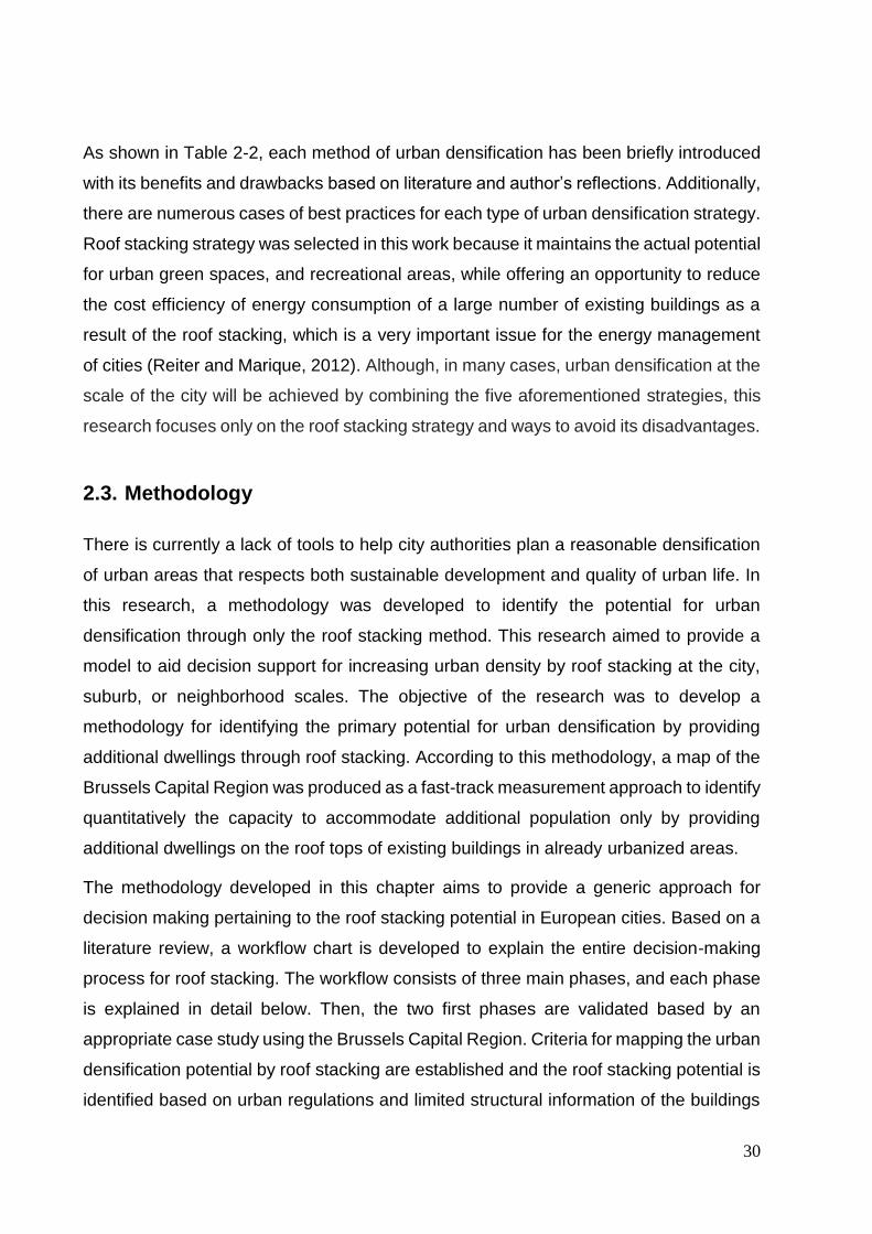
As shown in Table 2-2, each method of urban densification has been briefly introduced
with its benefits and drawbacks based on literature and author’s reflections. Additionally,
there are numerous cases of best practices for each type of urban densification strategy.
Roof stacking strategy was selected in this work because it maintains the actual potential
for urban green spaces, and recreational areas, while offering an opportunity to reduce
the cost efficiency of energy consumption of a large number of existing buildings as a
result of the roof stacking, which is a very important issue for the energy management
of cities (Reiter and Marique, 2012). Although, in many cases, urban densification at the
scale of the city will be achieved by combining the five aforementioned strategies, this
research focuses only on the roof stacking strategy and ways to avoid its disadvantages.
2.3. Methodology
There is currently a lack of tools to help city authorities plan a reasonable densification
of urban areas that respects both sustainable development and quality of urban life. In
this research, a methodology was developed to identify the potential for urban
densification through only the roof stacking method. This research aimed to provide a
model to aid decision support for increasing urban density by roof stacking at the city,
suburb, or neighborhood scales. The objective of the research was to develop a
methodology for identifying the primary potential for urban densification by providing
additional dwellings through roof stacking. According to this methodology, a map of the
Brussels Capital Region was produced as a fast-track measurement approach to identify
quantitatively the capacity to accommodate additional population only by providing
additional dwellings on the roof tops of existing buildings in already urbanized areas.
The methodology developed in this chapter aims to provide a generic approach for
decision making pertaining to the roof stacking potential in European cities. Based on a
literature review, a workflow chart is developed to explain the entire decision-making
process for roof stacking. The workflow consists of three main phases, and each phase
is explained in detail below. Then, the two first phases are validated based by an
appropriate case study using the Brussels Capital Region. Criteria for mapping the urban
densification potential by roof stacking are established and the roof stacking potential is
identified based on urban regulations and limited structural information of the buildings

Chapter 2: Determining the potential of urban densification through roof stacking
31
using ArcGIS (Geographical Information System) software, and the information available
in the Brussels GIS database. The presentation of the case study is followed by
discussion and criticism debating the generalization potential of the applied methodology
at the scale of Europe and highlighting the limitations and potential development of the
methodology to increase its robustness. The following sections describe the steps
undertaken in detail.
The workflow chart
The workflow chart is a methodology that is applicable at different urban scales, such as
the scale of a city, town, suburb, or specific neighborhood. The proposed workflow chart,
as shown in Figure 2.2, is divided into three main consecutive phases of decision
making. The first phase focuses on the urban and policies configurations of the selected
urban cadaster. An urban cadaster includes the geometric description of land parcels
with up-to-date land information. The second phase focuses on the generic structural
configurations of the urban cadaster. The third and last phase focuses on the detailed
architectural and structural configurations of each separate building and acquiring the
owner’s approval. On the basis of theory, the methodology provides the theoretical
foundation for implementation of roof stacking at the urban level, while in practice, it is
intended to represent a systematic approach for urban planners and decision makers at
the municipal level. Thus, it represents a top-bottom approach, which goes from the
general to the specific, to estimate the potential of any city to accommodate increasing
population by the means of roof stacking, while taking into consideration the different
stakeholders at every level of the decision making process. One of the main objectives
of the proposed workflow is to overcome the deviation in urban densification that has
resulted from single-issue research approaches. The following sections describe each
phase in detail.
First phase: urban and policies configurations
The first phase of the workflow chart investigates the primary need and potential for
densification though increasing the vertical heights of residential buildings according to
the policies and regulations provided by the concerned municipality or city. These issues
are decided and implemented by urban planners and decision makers at the municipal
level. First, the need for densification is based on various reasons, such as the expected
increase in population in a certain area, adhering to the urban agenda for compact cities,

32
or even on individual requests to raise a rooftop. Second, some buildings will be listed
as heritage buildings with either restrictions or prohibitions for modification. Once a
building is listed as a heritage structure, minimal intervention or no intervention at all can
take place. Then, the policies and regulations that allow roof stacking and an increase
of buildings heights are reviewed by policy makers, who consider the maximum height,
urban daylighting requirements, and accessibility to transportation networks and parking
plots.
At this level of analysis, two principal pieces of information are defined: first, the demand
for and applicability of densification through roof stacking, and second, the maximum
height that can be achieved based on the urban configurations.
Second phase: engineering configurations
In the second phase, the proposed decision making workflow utilizes additional
information provided by the GIS database to determine the potential and capacity for
roof stacking at the building block level. Structural configurations of the buildings may
be identified from existing data in the GIS database of the city. However, in this research,
the structure and foundation type were identified based on the year of construction and
the corresponding building prototypes in Brussels due to limitations in the available data.
Based on the structural analysis of the existing buildings, soil, actual height, estimated
additional weight per square meter, and the potential for roof stacking can be identified.
It is important to mention that the first two phases aim to provide only a fast-track
measurement of the potential increase of the number of stories for each building. The
uncertainty of the final results is inversely proportional with the available data used in
the first two phases. The more data attained at the urban and structural level, the more
accurate the results can be.

Chapter 2: Determining the potential of urban densification through roof stacking
33
Figure 2-2: Workflow chart

34
Third phase: architectural configurations
The third and last phase is focusing on the detailed assessment of the blocks having
potential for roof stacking. At this level, the participation of each of the architects,
engineers, and homeowners takes place with direct coordination with the municipality. It
represents the grass-roots level of decision making for roof stacking configuration at the
building level. Given that the first two phases provide only approximate guidance, the
third phase aims to provide actual and precise measurements. Once primary approval
is achieved in the third level, detailed analyses on the architectural and structural scale
are undertaken. At the structural level, detailed structural analysis should be done to
calculate the actual strength of the existing structures. According to the ISO 13822 (ISO
13822, 2010), a statement of principles and procedures is provided to assess the
structures of the existing buildings. Based on several factors, the type of tests, which
may range from non-destructive testing methods (NDT) to destructive testing methods
(DT), are identified (Leonard Runkiewicz, 2009).
Based on the strength of the actual buildings, precise estimations for the number of
floors that can be added can be provided. While on the architectural level, existing
architectural plans are acquired and new plans with the added stories are proposed,
along with further calculations for the sewage and sanitation capacities and feasibility
studies. Based on the results of the analysis, a second and final approval can be
undertaken based on the feasibility studies made for the project. Accordingly, the
implementation phase begins to take place.
2.4. Case study
Because this research is concerned with the potential for roof stacking specifically in the
context of Europe, the Brussels Capital Region, as the capital of Belgium, was chosen
as a case study to validate the workflow and the methodology developed in this research.
Among the cities in Belgium, Brussels has the fastest growing population, with an
expected 190,000 additional inhabitants by 2040, and the additional challenge of the
entire regional territory being fully urbanized (Deboosere, 2010a; Paryski and
Pankratieva, 2012a). The reason behind the city’s population growth dates back to the
1990s as a result of two main phenomena. The first is an increase in the rate of
international migration, prompted by individuals seeking better employment
Chapter 2: Determining the potential of urban densification through roof stacking
35
opportunities, and the second is the reinvigoration of birth rate. The population of
Brussels increased by 225,000 inhabitants in just the 20 years preceding 2015 (an
average of 11,250 people per year) to 1.100 million at the beginning of this year. Over
the same period, the number of households increased by 75,500 units, with an average
of 3,800 units per year (Dessouroux et al., 2016). Accordingly, the change resulted in an
average population density of the region of slightly more than 66 inhabitants/ha
(including non-constructible areas). However, this density varies greatly from one
neighborhood to another. In 2010, the densest neighborhood had 362.43 inhabitants/ha,
while the least densely populated area had only 2.64 inhabitants/ha, which provides
additional space to accommodate increasing population without loss of urban quality.
The dominant socioeconomic groups living in the central part of Brussels are the middle-
and low-income groups; the higher income groups live outside the city’s center
(Dessouroux et al., 2016).
As a consequence of the increase in the population of Brussels, the government has
implemented several infill developments and housing projects. Approximately 5,000
housing units are being produced annually in Brussels. These housing units are divided
into three main categories. The first category is public housing, which takes a 10% share
of the housing units. Under the first category, there are two types of public housing
provided by the government. One of these is social housing, which covers only 15% of
the public housing development and consists of rentable housing for low-income
households. One disadvantage of this type of public housing is the long waiting period
between application and actual habitation. The remaining share of the public housing is
in the form of subsidized housing, based on a public-private partnership, for which the
cost of a square meter should not exceed 1500 EUR. This type of housing targets
middle-income households. The second category, which takes a 70% share of the
housing units, is for private market built by private developers. The third category, with
a 20% share of the total annual housing units, is basically for private ownership
(Dessouroux et al., 2016; Vanneste et al., 2008).
Accordingly, there is an obvious shortage in the provisioning of housing for the low- and
middle-income social classes, which creates a burden on the government to change its
policies toward providing more housing for these classes (Decker, 2008, 1990). The first
reason behind the current lack of supporting public housing is the limited amount of
public land that can be directed toward public housing. The second reason is the fact
36
that the majority of the homes offered are more appropriate for the higher economic
classes and less so for the economically lower ones because the price of land per square
meter in Brussels is very high compared with peri-urban and rural areas in Belgium. The
third reason is due to the “not in my back yard” (NIMBY) effect, in which existing
residents oppose social housing projects that are close to them. However, according to
the Royal Decree “Urban Planning Charges”, new regulations require 30% social
housing, in some conditions, for new developments. Nevertheless, it is important to find
new opportunities for land for middle-income households. In this section, the
methodology developed to assess roof stacking potential is examined using the Brussels
Capital Region as a case study to identify and quantify the number of dwellings that
could be provided only through roof stacking and to answer the question of whether roof
stacking can be a successful alternative solution to accommodate the expected
population growth with a reasonable increase in urban density.
Urban and policies configurations
Heritage buildings
Brussels comprises five sites under the protection of UNESCO, where urban intervention
in the form of building densification is severely limited as shown in Figure 2-3.
Additionally, there are various sites subject to strong heritage protection. For zones of
strong protection, intervention by roof stacking is excluded completely, so these zones
were withdrawn from our mapping process of the densification potential of Brussels.
There are also various sites subject to weak heritage protection. The weak protection
zone has a restrictive criterion for densification of buildings, but it does not completely
prohibit densification; therefore, we did include these areas in our mapping process of
the densification potential of Brussels.
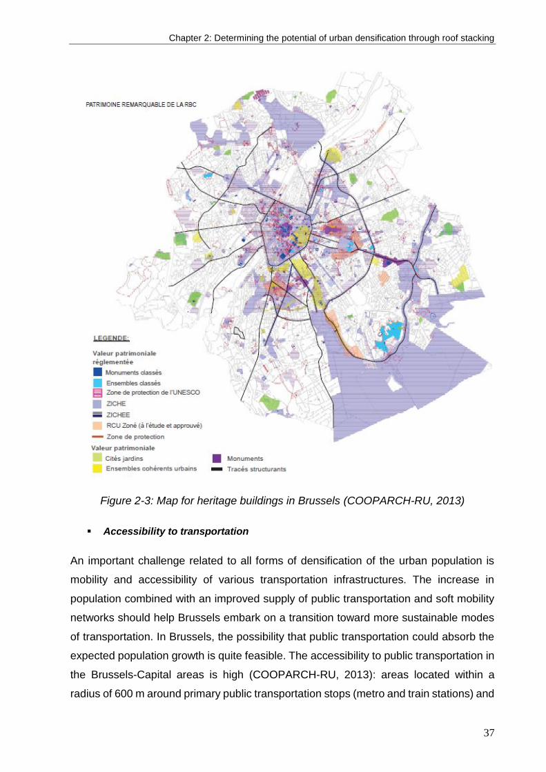
Chapter 2: Determining the potential of urban densification through roof stacking
37
Figure 2-3: Map for heritage buildings in Brussels (COOPARCH-RU, 2013)
Accessibility to transportation
An important challenge related to all forms of densification of the urban population is
mobility and accessibility of various transportation infrastructures. The increase in
population combined with an improved supply of public transportation and soft mobility
networks should help Brussels embark on a transition toward more sustainable modes
of transportation. In Brussels, the possibility that public transportation could absorb the
expected population growth is quite feasible. The accessibility to public transportation in
the Brussels-Capital areas is high (COOPARCH-RU, 2013): areas located within a
radius of 600 m around primary public transportation stops (metro and train stations) and
38
within a radius of 400 m around tramway stops cover more than 60% of the whole area
of the Brussels Capital Region, and a large number of bus stops completes this potential.
Moreover, a reasoned densification of Brussels should include the reinforcement of
infrastructures for the soft modes network of transportation in order to facilitate walking,
bicycling, and using electric bicycles, which have a real potential in urban environments
because journeys are on average short. From this analysis, no building in the Brussels
Capital Region was excluded from our mapping process of the roof stacking potential of
Brussels on the basis of a lack of accessibility to transportation networks.
Accessibility to parking areas
In Brussels, it should be easy to provide additional parking space for roof-stacked
buildings in the peripheral zones because of the low build density there, but in the very
dense areas of the city center, location of these additional parking spaces is an essential
requirement for good acceptance of urban densification. Even if the problem of
establishing a car park is managed on a case-by-case basis, regional authorities could
effectively increase parking spaces to meet the demand of the projected densification
by adding parking levels to existing open-air car parks.
The number of car parks currently located in the Brussels Capital Region according to
the Ministère la Région du Bruxelle Capital (MRBC) is 9,425 different parking areas,
including 325 car parks with an area of more than 1,000 m² each (COOPARCH-RU,
2013). The threshold of 1,000 m² was chosen for two reasons. First, it corresponds to a
car park with a capacity of 50 cars, using an average area of 20 m² per car (parking plus
traffic infrastructure between parking spaces), and second, open-air parking areas of
more than 1,000 m² represent a realistic potential for adding additional levels. These
open-air car parks of more than 1,000 m² in Brussels currently cover 68,681 m² of
parking area on a single level. This area provides potential for substantially increasing
the number of parking spaces in Brussels. Finally, a modal shift to public transportation,
carpooling and shared car systems, and soft mobility that does not include motorized
transportation, such as walking and bicycling, should be encouraged. From this analysis,
no building in the Brussels Capital Region was excluded from our mapping process of
the roof stacking potential of Brussels on the basis of a lack of accessibility to parking
area.
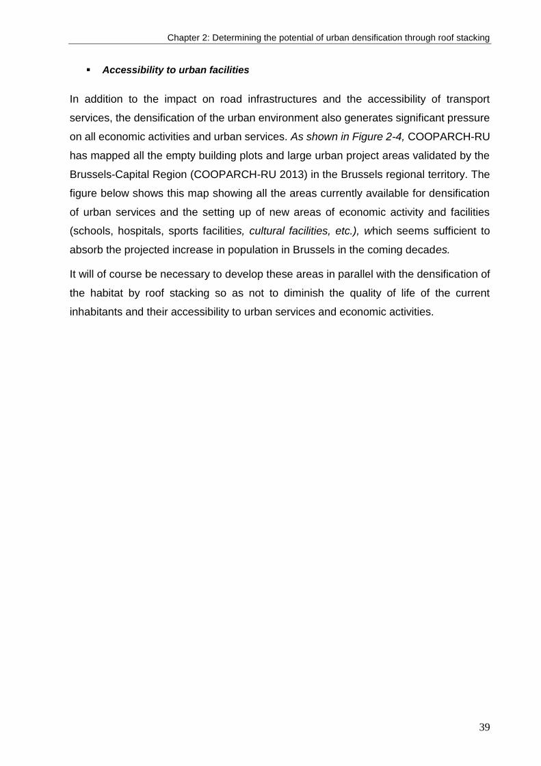
Chapter 2: Determining the potential of urban densification through roof stacking
39
Accessibility to urban facilities
In addition to the impact on road infrastructures and the accessibility of transport
services, the densification of the urban environment also generates significant pressure
on all economic activities and urban services. As shown in Figure 2-4, COOPARCH-RU
has mapped all the empty building plots and large urban project areas validated by the
Brussels-Capital Region (COOPARCH-RU 2013) in the Brussels regional territory. The
figure below shows this map showing all the areas currently available for densification
of urban services and the setting up of new areas of economic activity and facilities
(schools, hospitals, sports facilities, cultural facilities, etc.), which seems sufficient to
absorb the projected increase in population in Brussels in the coming decades.
It will of course be necessary to develop these areas in parallel with the densification of
the habitat by roof stacking so as not to diminish the quality of life of the current
inhabitants and their accessibility to urban services and economic activities.

40
Figure 2-4: Map for heritage buildings in Brussels (COOPARCH-RU, 2013)
Moreover, there is enormous potential for land availability in the peri-urban area of
Brussels, just outside the Region. In this peripheral area there are about 1,500 hectares
of land available for economic activity in Walloon Brabant and 1,200 hectares of land
available for economic activity in Flemish Brabant. In addition, there are more than 6,000
hectares of land situated in extension of the habitat available in Walloon Brabant and
3,800 hectares available in Flemish Brabant. These areas, however, must remain the
ultimate densification solutions because they are poorly served by public transport in
particular.
Similar studies have been carried out for the region of Flanders where urban
densification opportunities have been based on node value and proximity to urban
services (Verachtert, et al. 2016) as shown in Figures 2-5 and 2-6.
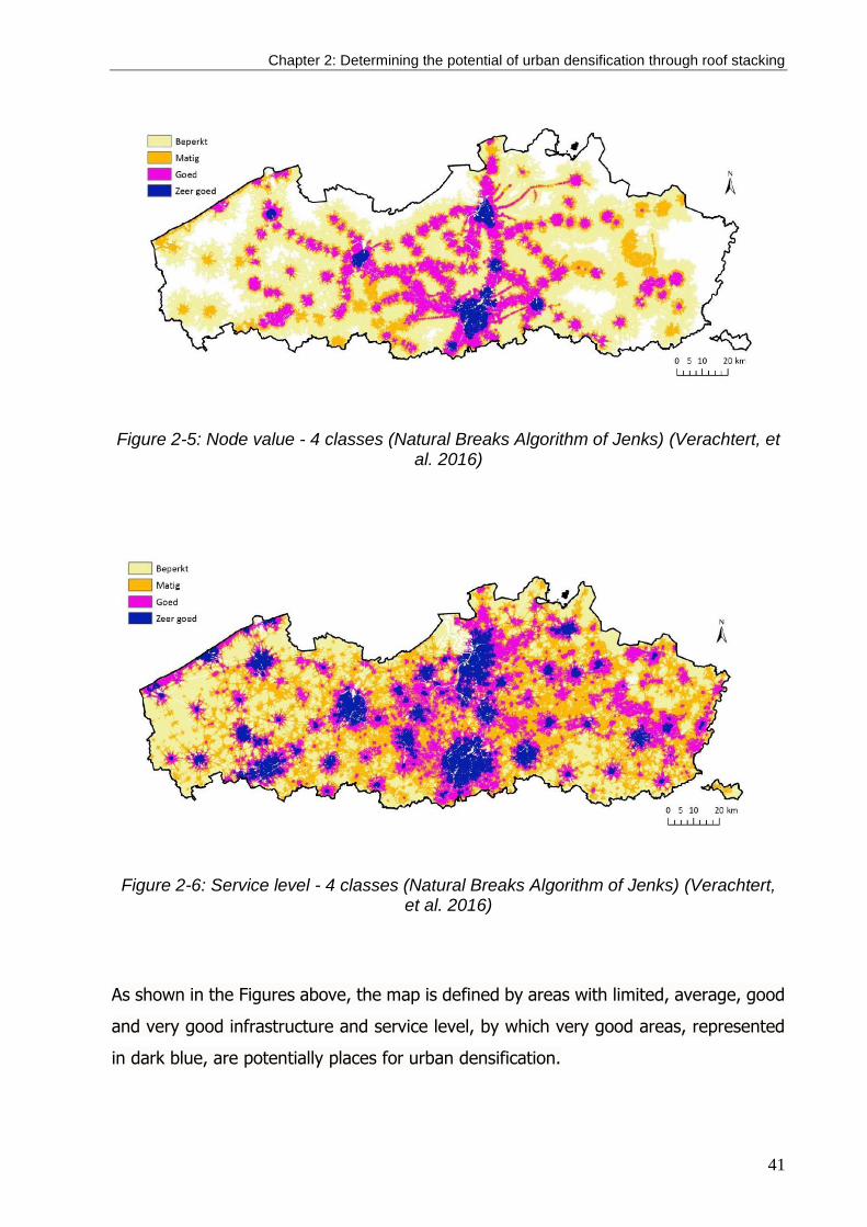
Chapter 2: Determining the potential of urban densification through roof stacking
41
Figure 2-5: Node value - 4 classes (Natural Breaks Algorithm of Jenks) (Verachtert, et al. 2016)
Figure 2-6: Service level - 4 classes (Natural Breaks Algorithm of Jenks) (Verachtert, et al. 2016)
As shown in the Figures above, the map is defined by areas with limited, average, good
and very good infrastructure and service level, by which very good areas, represented
in dark blue, are potentially places for urban densification.

42
Accessibility to public green spaces
There are nearly 4,000 hectares of green spaces in the Brussels Capital Region,
representing approximately 25% of the territory as shown in Figure 2-7. The density of
public green spaces in 2010 was about 36 m² per inhabitant (COOPARCH-RU, 2013),
whereas the sustainable urban planning recommendation is at least 10 m² of public
green spaces per inhabitant (De Herde et al., 2009). Moreover, these green spaces are
well distributed across Brussels’ territory. From the perspective of accessibility to public
green spaces, the population of Brussels could triple without any problem caused by
roof stacking because densification by roof stacking increases the number of inhabitants
without diminishing access to green spaces. There is therefore a very large potential for
densification by roof stacking in Brussels with regard to green spaces. No building in the
Brussels Capital Region was excluded from our mapping process of the roof stacking
potential in Brussels on the basis of a lack of accessibility to green spaces.
Figure 2-7: Green areas in Brussels

Chapter 2: Determining the potential of urban densification through roof stacking
43
Maximum allowable building height
According to the urban regulations of the Brussels Capital Region, the height of the front
façade has to be determined in accordance with the height of the two neighboring
facades (considering them as the reference height): it cannot be less than the lowest
reference height, cannot be more than the highest reference height, and not be more
than 3 m above the lowest reference height. However, the allowable height for new or
roof-stacked buildings may also be determined as the mean average height of the other
buildings on the street. For simplicity, this last rule (mean height of the buildings on the
street block) was applied to fix the maximum allowable height for roof stacking in
Brussels in our mapping process for scenario 1, corresponding to the actual urban
regulation in Brussels. However, if we consider the possibility that this criterion of
maximum height of buildings could be relaxed in the near future to facilitate the
construction of new dwellings to accommodate the expected population increase, it
seems important to select a minimum criterion of natural light accessibility, which is
explained in detail in the following subsection.
Accessibility to daylighting
Preserving the natural daylighting of existing buildings during an urban densification
operation is obviously essential. For Brussels, there are no well-defined rules imposed
to ensure accessibility to natural light, but the maximum allowable building height is a
very strict criterion that also ensures this right to daylighting of neighboring buildings.
International research recommendations provide for the latitude of Brussels an
acceptable limiting obstruction angle equal to 25 °, which must be taken from a height
of 2 m above street level on the building’s façade (Littlefair et al., 2000). From this rule,
the maximum building height can be identified for each building based on the relation
between street width and existing buildings heights, which has been calculated based
on the street width map as shown in Figure 2-8. This rule was applied to fix the maximum
allowable height for roof stacking in Brussels in our mapping process for scenario 2,
corresponding to an optimistic scenario for densification by roof stacking while still
preserving the quality of life of neighbors.

44
Figure 2-8: Street width map
Structural configurations of buildings
To estimate the potential number of stories that could be added to existing buildings,
some information must be provided and investigated. However, at the urban level,
detailed information can seldom be acquired, especially information pertaining to the
structural analysis of existing buildings. Thus, in this method, a set of criteria to be
utilized in a systematic approach to roughly estimate the potential number of floors that
could be added to existing buildings using a minimum amount of information was
developed. According to Figure 2.9, some information is required to identify the potential
for roof stacking: the type of existing building structure, soil properties, area of land plot,
and number of existing floors. The estimated weight added per square meter is an
additional piece information needed to estimate this potential number of added floors.
However, in some cases, it is nearly impossible to acquire precise data from the GIS
database at the building scale level, either because of an absence of resources or
because there were onsite changes that were not updated in the database. Thus,
estimations for building configuration and soil calculations were set as explained below.

Chapter 2: Determining the potential of urban densification through roof stacking
45
Figure 2-9: Structural mapping for roof stacking potential
Building typology
Existing residential buildings were categorized into two periods: residential buildings built
before 1945 and residential buildings built between 1946 and 1975. Residential buildings
that were built after 1975 were excluded from the analysis. The year 1945 marks the
end of the WWII and the beginning of an industrialized period in the field of construction.
Residential buildings constructed before 1945 represent 71% of the existing residential
buildings in Brussels. The second threshold defined by the year 1975 was chosen as a
threshold of the analysis and mapping process because the number of residential
buildings built after 1975 is negligible. These buildings represent less than 3% of all the
existing residential buildings and have a much greater disparity of architectural
typologies and materials. The proportion of residential buildings built between 1945 and
1975 is 26%, and the typologies used in the residential building sector did not change
dramatically for the structural calculation of low- and mid-rise buildings. According to the
De Taeye Law, housing production was directed away from large-scale, multi-storey,
and collective housing projects until the late 1970s (Van de Voorde et al., 2015a).
Residential building typologies did not change dramatically, and people and construction
industries were still conservative compared to other countries in Europe during this
period. Changes were observed in the building materials used, such that heavy bricks
were replaced with lightweight bricks and wooden masonry joist slabs were replaced
with lightweight concrete slabs.

46
The illustration in Figure 2.10 presents the percentages of the different residential
building typologies before 1945. The majority of buildings were classified as middle-class
houses, which represent 78% of the total. Figure 2.11 shows the typical layout of the
middle-class house typology, which was selected in this study as a unified reference to
building configurations in terms of percentage thickness of walls and foundation (Van de
Voorde et al., 2015a). Accordingly, building materials and their properties could be
identified easily and unified in the mapping test process. In this example, the average
weight of walls was identified to be 1,900 kg/m2, that of wooden slabs was estimated to
be 100 kg/m2, and live loads were 200 kg/m2. For buildings constructed after WWII, the
average weight of walls was identified to be 1200 kg/m2, and live loads remained
constant (Van de Voorde et al., 2015a).
Floor area and number of floors
Data of floor area and number of actual floors are available in the Brussels GIS
database, which was used in this stage of the analysis. The data are updated yearly by
the cadaster administration in the Ministry of Finance in Belgium. It was observed that
99% of the residential buildings have between 1 and 5 floors. Thus, in our mapping
process of the densification potential, the analysis was carried out on only buildings with
Figure 2-10: Housing typologies before 1945
Figure 2-11: Middle class housing typology
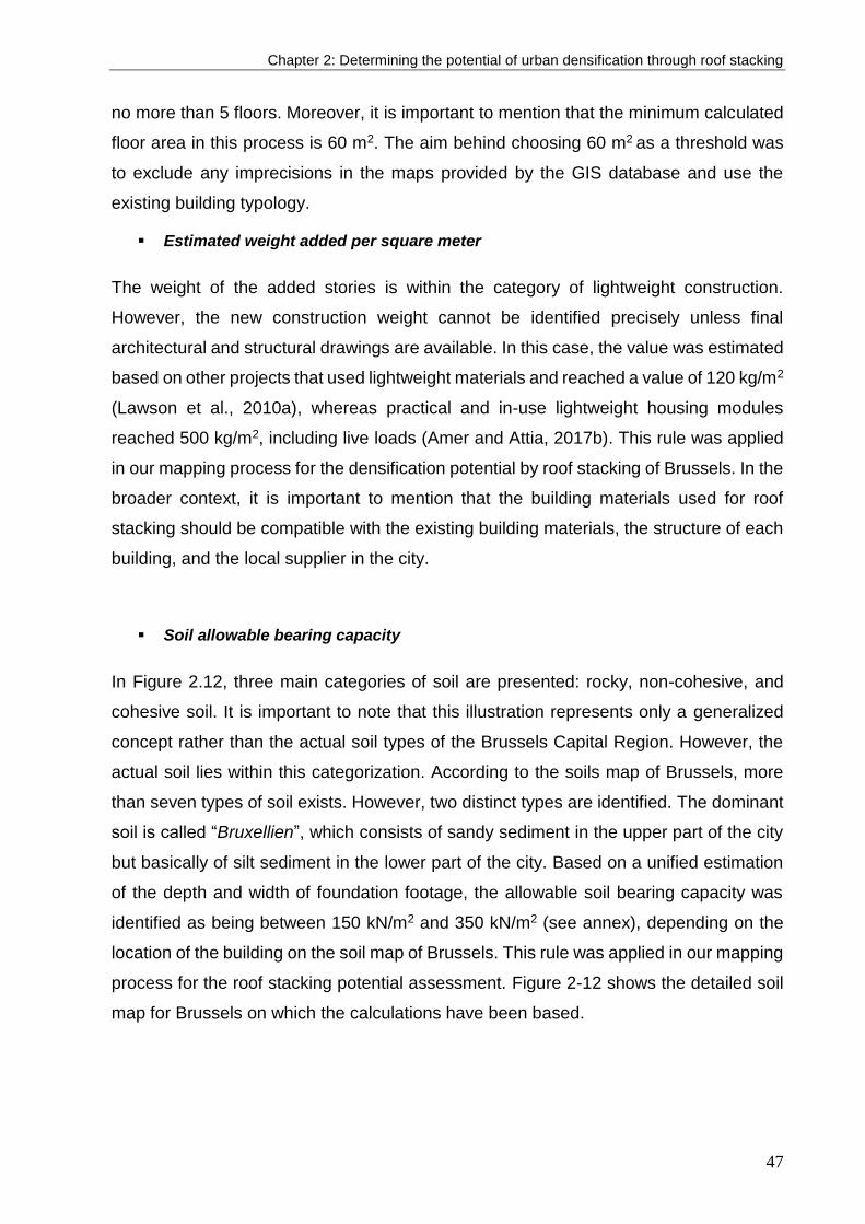
Chapter 2: Determining the potential of urban densification through roof stacking
47
no more than 5 floors. Moreover, it is important to mention that the minimum calculated
floor area in this process is 60 m2. The aim behind choosing 60 m2 as a threshold was
to exclude any imprecisions in the maps provided by the GIS database and use the
existing building typology.
Estimated weight added per square meter
The weight of the added stories is within the category of lightweight construction.
However, the new construction weight cannot be identified precisely unless final
architectural and structural drawings are available. In this case, the value was estimated
based on other projects that used lightweight materials and reached a value of 120 kg/m2
(Lawson et al., 2010a), whereas practical and in-use lightweight housing modules
reached 500 kg/m2, including live loads (Amer and Attia, 2017b). This rule was applied
in our mapping process for the densification potential by roof stacking of Brussels. In the
broader context, it is important to mention that the building materials used for roof
stacking should be compatible with the existing building materials, the structure of each
building, and the local supplier in the city.
Soil allowable bearing capacity
In Figure 2.12, three main categories of soil are presented: rocky, non-cohesive, and
cohesive soil. It is important to note that this illustration represents only a generalized
concept rather than the actual soil types of the Brussels Capital Region. However, the
actual soil lies within this categorization. According to the soils map of Brussels, more
than seven types of soil exists. However, two distinct types are identified. The dominant
soil is called “Bruxellien”, which consists of sandy sediment in the upper part of the city
but basically of silt sediment in the lower part of the city. Based on a unified estimation
of the depth and width of foundation footage, the allowable soil bearing capacity was
identified as being between 150 kN/m2 and 350 kN/m2 (see annex), depending on the
location of the building on the soil map of Brussels. This rule was applied in our mapping
process for the roof stacking potential assessment. Figure 2-12 shows the detailed soil
map for Brussels on which the calculations have been based.
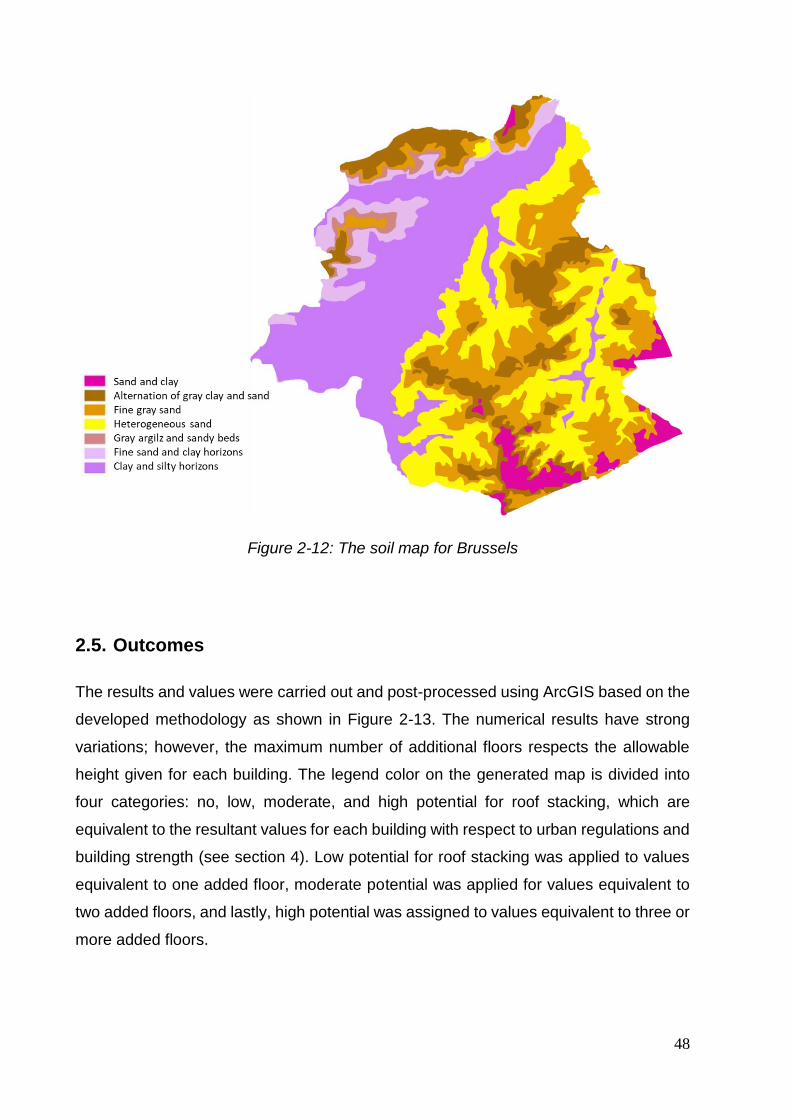
48
Figure 2-12: The soil map for Brussels
2.5. Outcomes
The results and values were carried out and post-processed using ArcGIS based on the
developed methodology as shown in Figure 2-13. The numerical results have strong
variations; however, the maximum number of additional floors respects the allowable
height given for each building. The legend color on the generated map is divided into
four categories: no, low, moderate, and high potential for roof stacking, which are
equivalent to the resultant values for each building with respect to urban regulations and
building strength (see section 4). Low potential for roof stacking was applied to values
equivalent to one added floor, moderate potential was applied for values equivalent to
two added floors, and lastly, high potential was assigned to values equivalent to three or
more added floors.
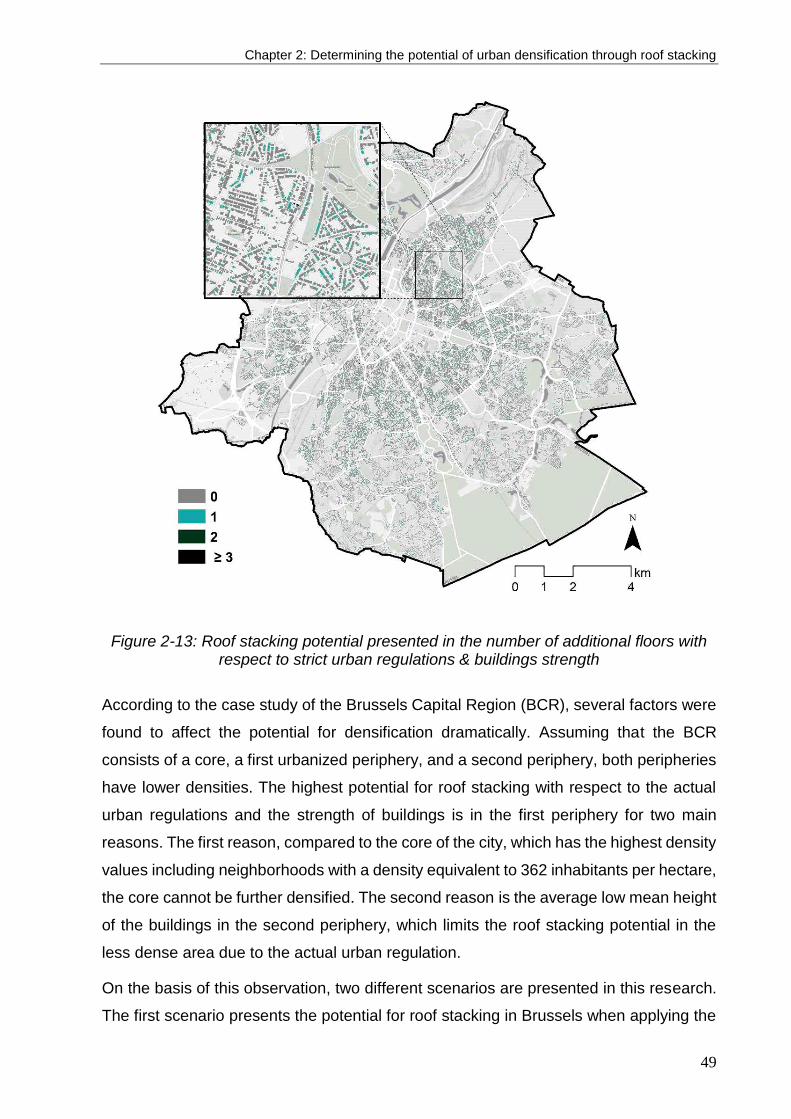
Chapter 2: Determining the potential of urban densification through roof stacking
49
Figure 2-13: Roof stacking potential presented in the number of additional floors with respect to strict urban regulations & buildings strength
According to the case study of the Brussels Capital Region (BCR), several factors were
found to affect the potential for densification dramatically. Assuming that the BCR
consists of a core, a first urbanized periphery, and a second periphery, both peripheries
have lower densities. The highest potential for roof stacking with respect to the actual
urban regulations and the strength of buildings is in the first periphery for two main
reasons. The first reason, compared to the core of the city, which has the highest density
values including neighborhoods with a density equivalent to 362 inhabitants per hectare,
the core cannot be further densified. The second reason is the average low mean height
of the buildings in the second periphery, which limits the roof stacking potential in the
less dense area due to the actual urban regulation.
On the basis of this observation, two different scenarios are presented in this research.
The first scenario presents the potential for roof stacking in Brussels when applying the

50
actual strict urban regulations. The second scenario presents a proposal in which urban
regulations are not fully applied. The regulation related to allowable maximum height
based on the mean height of the buildings on the street is excluded, and a more relaxed
regulation related to the allowable maximum height based on daylight availability is
proposed. This second scenario aims to increase the densification potential in
neighborhoods that currently have a low density and include many buildings with low
height, while aiming to maintain outdoor environmental quality in addition to indoor
daylight availability for neighboring buildings. A second goal of this scenario is to
facilitate the construction of a higher number of new dwellings to accommodate the
expected population increase by 2040. Consequently, the second scenario results in a
higher potential for roof stacking, improving the ability of the city to accommodate greater
population in the coming years. Additionally, each scenario consists of two steps based
on the steps presented in the workflow chart: urban and policies configurations and
building structural configurations. Thus, the first step presents the values according to
the urban regulations of the BCR, whereas the second step presents the values when
considering the buildings’ tendencies to hold more weight based on their actual structural
capacity. The rationale for presenting both steps is to validate the proposed workflow
chart by testing the influence of building strength on the resultant values. It is important
to mention than the calculations were made based on the average living area consumed
by an inhabitant, which is 35 m2. This area does not include the building service areas
(stairs, hallways, etc.), which are equivalent to an addition of 9%. Thus, the total
consumption of floor area is equivalent to 38.15 m2 per inhabitant.
In the first scenario, by applying urban regulations (first step), it was found that the BCR
is capable of hosting more than 60,400 additional inhabitants, which is equivalent to 32%
of the expected increase in population. However, when considering the actual building
strength (second step), as shown in Figure 2-13, the number is only reduced to 59,000
additional inhabitants, which is equivalent to 30% of the expected increase in population,
a difference of 2%, which is equivalent to a roughly 50,000 m2 reduction of roof stacking
potential. In Figures 2.14 and 2.15, the difference is presented at the municipality level,
at which the 2% difference does not represent a large reduction due to the strict
limitations provided by the actual urban regulations, which explains why Figures 2.16
and 2.17 appear to be similar. This comparison is further presented with numbers in
Table 2.3.

Chapter 2: Determining the potential of urban densification through roof stacking
51
Figure 2-14: Roof stacking potential in km2 per municipality respecting strict
urban regulations only
Figure 2-15: Roof stacking potential in km2 per municipality respecting strict urban regulations & buildings strength
Figure 2-16: Roof stacking potential in km2 per municipality respecting flexible
urban regulations only
Figure 2-17: Roof stacking potential in km2 per municipality respecting flexible urban regulations & buildings strength

52
When applying the first step of the second scenario of analysis, corresponding to flexible
urban regulations respecting the daylighting rule, the potential for roof stacking increases
dramatically. It was found that the BCR is capable of hosting more than 655,500
additional inhabitants, which is equivalent to 245% more than the expected increase;
however, when considering buildings’ strength, the number is reduced to 509,000
inhabitants, 160% more than the expected increase in population. The influence of
applying the structural configurations of the existing buildings in the calculation of roof
stacking potential at the city scale in this second scenario is huge, equivalent to an 85%
difference in the population increase potential between the first and the second steps,
which is contrary with the first scenario. In Figures 8 and 9, which present the two steps
of the second scenario, the differences in the densification potential of these steps at the
municipality level are obvious, as is illustrated in Table 2.3.
Table 2-3: The potential area in square meter of roof stacking per municipality in BCR
Municipality Scenario 1.1 (m2)
Scenario 1.2 (m2)
Difference (%)
Scenario 2.1 (m2)
Scenario 2.2 (m2)
Difference (%)
Brussels 347,590 335,292 3.5% 3,110,873 2,304,217 25.9%
Uccle 254,175 253,877 0.1% 3,705,901 2,924,293 21.1%
Schaerbeek 239,681 234,235 2.3% 2,571,445 1,865,630 27.4%
Anderlecht 186,051 179,712 3.4% 2,049,771 1,500,785 26.8%
Ixelles 168,329 168,361 0.0% 1,317,597 1,160,589 11.9%
Forest 140,706 134,388 4.5% 1,129,145 794,581 29.6%
Woluwe St.Pierre
132,784 132,791 0.0% 1,957,348 1,649,133 15.7%
Etterbeek 116,335 116,340 0.0% 907,854 714,278 21.3%
Molenbeek St.Jean
115,870 108,162 6.7% 1,004,072 555,645 44.7%
Woluwe St.Lambert
99,938 99,794 0.1% 1,386,510 1,177,485 15.1%
Jette 89,048 88,880 0.2% 981,695 786,070 19.9%
St-Gilles 87,976 80,579 8.4% 581,045 408,193 29.7%
Berchem St.Agathe
64,216 64,219 0.0% 625,708 520,949 16.7%
Auderghem 58,386 58,124 0.4% 1,019,980 889,881 12.8%
Evere 54,758 54,751 0.0% 677,113 554,895 18.0%
Watermael-Boitsfort
48,183 48,178 0.0% 1,061,831 889,865 16.2%
Koekelberg 39,430 38,616 2.1% 288,169 203,650 29.3%
Ganshoren 30,859 30,745 0.4% 413,737 356,363 13.9%
St.Joost 29,362 29,017 1.2% 219,382 165,508 24.6%
Chapter 2: Determining the potential of urban densification through roof stacking
53
In the second step of the second scenario of roof stacking, when given the opportunity
to expand the maximum allowable height, it was found that the underlying soil greatly
affects the final results by modifying the maximum load acceptable for the buildings and
thus their calculated strength. In the case of the BCR, the soil in the eastern and southern
parts of Brussels is called “Bruxellien” and consist of sandy sediment with high allowable
bearing pressure, but in the northern and western parts of the city, the soil basically
consists of silt with low allowable bearing pressure. Accordingly, when comparing the
first and second steps in the second scenario, the difference in the potential for roof
stacking in the municipalities in the north is 25%, whereas the difference is only 16% in
the municipalities in the south because these municipalities overlie stronger soil.
However, from the technical perspective, it is possible to increase the height of the
existing buildings, adding floors on a building that cannot hold more weight requires
additional reinforcement and therefore extra budget. Nevertheless, in this research, roof
stacking that depends on the actual strength of the existing building and soil is only
considered for reasons of cost efficiency. In the case study of Brussels, the roof stacking
potential assessment relies on the total load bearing of the new structure on the existing
bearing walls of the buildings, thus structural limitations affect these results.
The results produced for Brussels at the city scale using the second scenario show that
there should be a real interest in re-examining the current urban regulations to take into
account the great need for new housing in this city by 2040. Moreover, the potential
number of dwellings produced by roof stacking densification based on this second
scenario is enormous. However, such an increase in the building stock cannot be
accomplished without simultaneously addressing different urban and social issues, such
as increasing various urban services (schools, hospitals, etc.) and facilities, increasing
the capacities of modes of public transportation in the densified parts of the city, having
a global reflection on the alterations to urban morphology, social factors, and mobility
issues, and assessing the impacts of this densification on urban sustainability, resiliency,
and health. A first reflection on these aspects was already begun in section 2.4, which
defined our case study, but a concrete modification of the current urban planning
regulation on the maximal building height in Brussels would require a more detailed
study of these different aspects and of all the potential consequences of such an
increase in population on the existing living environment of Brussels.
54
2.6. Discussion
Presently, urban planning agendas are promoting reasonable urban densification as a
sustainable development approach toward increasing the compactness of cities. From
this approach, this research presented a workflow scheme to support decision making
while simultaneously identifying and mapping the potential for roof stacking. This article
was developed in three phases: (1) a literature review, (2) development of a decision-
making workflow and various screening criteria for assessment of roof stacking potential,
and (3) validation of the proposed methodology using a case study: the Brussels Capital
Region. The roof stacking potential in Brussels, based on the actual urban regulations
(including a strict rule on building maximal height), provides 30% of the additional
required residential living space in Brussels needed by 2040 due to population increase.
These results also show a real need for re-examining current urban regulations from the
perspective of the roof stacking densification potential of cities, which are facing a need
for a large number of new housing structures in the near future, provided that the
consequences of this type of urban densification on the quality of life of the city’s
inhabitants are studied on a case-by-case basis and taken into account for sustainability.
Several challenges deter progress in developing such roof stacking projects on a broad
scale. Some are specifically related to Brussels, and others could be universal, such as
the “not in my back yard” (NIMBY) effect, which is the tendency of inhabitants to resist
housing development projects in their neighbourhood. Those that are specifically related
to Brussels include the high price of housing construction. This tends to increase the gap
between real demand and supply in the housing market and create a shortage in
providing social housing. Another challenge is related to the housing market being
constrained to ownership rather than to renting. However, the figures in Brussels show
that renting is still higher than ownership, but it is relatively low compared to other cities
in Europe, such as Berlin (Vanneste et al., 2001).
In conclusion, European cities have great potential to be densified through the roof
stacking method. However, it is important to mention that a successful process of roof
stacking should integrate each of the urban and regulatory, technical and engineering,
and architectural and social participation aspects. Thus, this article presented a strategic
approach for roof stacking, while strengthening the importance of following a
multidisciplinary and institutional approach in the application of such projects.

Chapter 3: Conceptual framework for off-site roof stacking construction
55
3. Chapter Three: conceptual framework for
off-site roof stacking construction2
A great deal of interest in off-site construction has been remarkable over the last decade. However, building on the
rooftops of existing building has not been given a significant importance as a subject of
research, despite its dependence on off-site construction and prefabrication. Thus, this
chapter develops a novel conceptual framework to support a multidisciplinary decision
making for selecting off-site prefabricated constructional system for roof stacking. The
multidisciplinary approach includes each of safety, logistics, cost, time, environmental
impact, and quality of construction as major criteria in the decision making process. This
chapter is the outcome of an exhaustive investigation of more than 136 roof stacking
projects built during the last 20 years. The development of framework is supported by a
feedback validation loop based on semi-structured interviews with experts in the field of
roof stacking and off-site construction.
2 This chapter is based on this article: Amer, M., Attia, S. (2019 Conceptual framework for offsite roof stacking construction. Journal of Building Engineering. 26, 100873. https://doi.org/10.1016/j.jobe.2019. 100873.

56

Chapter 3: Conceptual framework for off-site roof stacking construction
57
3.1. Introduction
Conventional on-site construction “stick built” methods are being abandoned by building
engineers due to the associated long construction time, higher risk records, lower
productivity and vulnerability to outdoor weather conditions (Eastman and Sacks, 2008;
Egan, 1998). Instead, off-site construction methods have shown superior strength in
shortening construction time while providing higher safety records and overall quality
(Yee, 2001a, 2001b). Accordingly, off-site construction took a great deal of interest in
the last decades by building engineers worldwide. This interest is reflected by the
exponential number of off-site construction-based projects worldwide and the conducted
studies in the same field of research that aims to evaluate prefabrication methods’ impact
within the building industry and on environment (Goodier and Gibb, 2007a; Hosseini et
al., 2018a; Jaillon and Poon, 2014). Those studies were extended to include the
development of tools and decision support frameworks to optimize the modular
configurations and the selection of cranes, building materials and connections (Han et
al., 2018; Jato-Espino et al., 2014).
Despite the numerous studies conducted in this field, there is a significant lack of
integrating off-site construction and specifically prefabrication (as a method under the
off-site construction) research with roof stacking. Given that roof stacking practices are
highly based on off-site construction methods on its multiple levels, it has not been given
any importance by researchers in the field of building engineering. Building on the
rooftops of existing facilities is put forward by the United Nations (UN) agendas as a
sustainable approach towards achieving compact cities (United Nations, 2017a).
However, studies on roof stacking, such as that by Lawson et al. (2010), Floerke et al.
(2014), Tichelmann and Groß (2016), were rather general and descriptive. Despite the
added value of their studies, their work remain manuals, representing qualitative reviews
and lacking scientific validation. After an exhaustive review in the field of building
engineering in construction, two fundamental issues have been found that lead to this
shortfall, which are addressed in this chapter: (i) the lack of appropriate identification and
classification of the existing off-site construction methods and building materials that are
specifically used for roof stacking. (ii) The lack of a definitive framework on which building
engineers use to select the method of roof stacking construction.

58
Therefore, this chapter develops a novel framework to support a multidisciplinary
decision making for selecting off-site constructional system for roof stacking. A
structured quantitative method has been adopted to generate a comprehensive
framework that integrates roof stacking research and off-site construction practical
knowledge. The framework in this chapter is accomplished by developing a new
classification for contemporary roof stacking construction methods. Our research
approach is distinguished by: (i) adopting a multi-disciplinary approach that includes
each of safety, logistics, cost, time, on-site impact, and quality of construction. (ii)
Embracing a scientific validation approach for the developed framework by case studies
applications from representative experts in the field of off-site construction. Given that
early decision making affects 80% of the construction project’s on-site activities (Sharafi
et al., 2012; Sharafi P. et al., 2014), the outcomes of this research are aimed to
overcome the reluctance and lack of experience among building engineers to adopt
prefabrication by achieving higher ascertain decision (Schoenborn, 2012).
This chapter is composed of three main parts. The first part represented in section 3.2
and 3.3, explains the research methods used in this chapter, in addition to reviewing the
literature on roof stacking methods and classifications. The decision-making frameworks
concerning off-site, modular, and prefabricated construction have been also reviewed.
The second part is represented in section 4, where the classification process of roof
stacking construction methods is carried out. The last part represented in section 5
develops the decision-making framework of selecting roof stacking construction
methods, represented by the load bearing methods, assembly methods, and building
materials. At the end, the verification loop for the framework is explained.
3.2. Literature review
Background
Off-site construction adoption by the building industry returns back to early 1990’s, when
large number of residential buildings have been constructed using this building system
worldwide (Knaack et al., 2012; Lawson et al., 2014; Smith, 2011). Since then, a wide
number of research were conducted to develop and evaluate off-site construction and
prefabrication methods’ impact on the building industry and environment. Jaillon and
Poon (2008) conducted examination on the sustainable aspects when adopting

Chapter 3: Conceptual framework for off-site roof stacking construction
59
prefabrication in construction, in which each of the economic, environmental and social
aspects have been assessed. The same researchers followed their findings with
intensive review of literature and case studies to identify the benefits and drawbacks of
flexible and demountable building systems including prefabrication in buildings (Jaillon
and Poon, 2014). The research of Baldwin et al. (2008) focused on the evaluation of the
prefabricated and precast design solution when it comes to waste reduction in residential
buildings construction using modelling information flows in the design process. Lawson
et al. (2012) reviewed the technologies used in modular construction in Europe, showing
the application of cellular approach in modular construction on a wide range of building’s
height and form. Other research had the interest on developing decision making criteria
and indicators for nearly optimum selection of prefabricated construction method. Chen
et al. (2010a, 2010b) identified sustainable performance criteria on which the selection
of construction methods take place. Moreover, a tool has been developed based on the
identified criteria to assist building engineers to evaluate the feasibility of prefabrication
during the early design stages and exploring optimal construction measures. (Akadiri et
al., 2013) proposed a model based on fuzzy extended analytical hierarchy process for
optimum building material selection, providing solutions based on sustainability
principles and prioritization. Ceniceros et al. (2013) developed a sustainable decision
support model for selecting optimized design parameters for prefabricated floor slabs.
Similar research made by Jensen et al. (2012) aimed to demonstrate CAD tools as a
mean to create design automation alternatives for modularized building systems,
whereas Yuan et al. (2018) combined parametric design of Building Information
modelling (BIM) with Design for Manufacture and Assembly (DFMA) as a mean to
overcome the unsuitability of design systems, which have been developed for non-
prefabricated buildings, on prefabricated buildings. Another research by Said et al.
(2017) presents a platform optimization model for panelized wall systems. This platform
optimizes the trade-offs between fabrication cost and minimization of design deviations.
Salama et al. (2017) developed sustainability criteria using five indices to formulate a
modular suitability index (MSI) that aid the selection of near optimum module
configuration. Sharafi et al. (2018, 2017) developed an effective and automated method
based on a unified matrix that aids the selection of compromised spatial design
specifically for multi-storey modular buildings.
60
Research on roof stacking
Even though roof stacking is increasingly taking place worldwide with high potential in
major European cities (Amer et al., 2018, 2017a), very few literature was found that
studied this phenomenon. There have been a couple of attempts to classify roof stacking
in terms of approach, shape or structural capacity. (Floerke et al., 2014) gathered a large
number of roof stacking projects around the world in one catalogue. The catalogue
classifies the projects based on the shape of the added stories to end up in five shapes:
saddle shaped roof, cubic form aligning roof surface, set back extension, free form or
cantilevered, combined extension with the main building volume, and lastly juxtaposed
extension to the main building. (Tichelmann and Groß, 2016) made another
classification based on projects built Germany. The developed classification is based on
the constructive characteristics, number of added stories and the percentage of roof
space occupation. Four main categories were identified: one added saddle shaped roof,
one added flat roof floor, two added floors, and lastly three and more added floors. Other
research recommends roof stacking as an approach towards increasing urban density
showing several advantages in balancing between densification and urban landscape
preservation (Nilsson et al., 2014). Moreover, roof stacking showed a superior strength
in decreasing energy consumption compared to only roof renovation.
Roof stacking framework development and validation method
First, a wide investigation has been carried out on more than 137 roof stacking projects
constructed during the last 20 years around Europe. This investigation aims to identify
the contemporary construction methods used in roof stacking projects. Each project has
been analyzed based on their date of construction, building typology, structural system,
in addition to the building material of the existing and new construction. Accordingly, a
classification has been illustrated for each of the load bearing and assembly methods,
on which the framework has been developed.
To develop a meaningful conceptual framework for roof stacking construction, an
extensive review of literature has been conducted comprising over 40 publications in the
field of building engineering, prefabrication, modularity and off-site construction (Akadiri
et al., 2013; Arashpour et al., 2016, 2018; Dind et al., 2018). Some of those publication
are presented in Table 3-2 (Blismas et al., 2006; Eastman and Sacks, 2008; Goodier
and Gibb, 2007a; Hosseini et al., 2018a). The review has extended to include decision

Chapter 3: Conceptual framework for off-site roof stacking construction
61
making tools development (Amer and Attia, 2019a; Basbagill et al., 2014; Murtaza Mirza
B. et al., 1993). The aim was to overcome the shortage in literature in the field of roof
stacking by collecting and reviewing articles in same related areas, exploring factors
which may have an impact on roof stacking construction methods selection. Based on
the findings from the literature review, 6 factors were found to affect the decision-making
and choice of construction method and building materials, which counts for safety (S)
represented by the existing building’s strength and weight of the added modules,
logistics (L) represented by the existing urban context and dimensional constrains, cost
(C) represented by the cost of building materials and transportation, time (T) represented
by the time required to accomplish the construction off and on-site, Environmental
impact (E), and quality of construction (Q). Those factors have been followed by
questionnaires and interviews with building engineers to validate the findings. More
information on the method on literature and questionnaires’ statistics can be found here
(Amer and Attia, 2019a).
According to the established classification and identified construction method criteria of
selection, a framework has been developed based on multi-disciplinary attributes. The
framework has been divided into two sequential phases. The first phase is concerned
with examining the strength of the existing building and its capacity to hold additional
weight. A feasibility study is conducted by the end of this first phase to determine the
applicability to build on the rooftop. The second phase is concerned with the decision
making on the prefabrication assembly method. Three methods have been defined
based on six criteria, on which the decision making process takes place. The framework
has been refined and validated by reviewing the application of several case studies that
represent different methods of roof stacking. The validation process is based on reverse
engineering concepts, in which semi-structured interviews have been conducted with
building engineers with expertise in off-site construction and roof stacking. Those
experts are from different countries, such as Austira, Spain and Belgium. Each project
has been analyzed and broken down into 6 aspects corresponds to the predefined 6
criteria of construction methods selection. Lastly, this research reports the challenges
and opportunities in the application of each construction method.

62
3.3. Research methods
In this section, we present the methodology. Similar to the work of (Chen et al., 2010a),
(Salama et al., 2017a), (Wang et al., 2013) our methodology combines mixed research
methods that involves quantitative (e.g. case studies), and qualitative (e.g. interviews)
approaches. Qualitative data analysis in this research is characterized by being
thematic, represented by the investigated case study with a descriptive focus. This
research strongly relies on an in-depth and intimate understanding of individual case
studies, as well as quantitative analysis that is based on field research and statistical
inference of the roof stacking case studies around Europe. The aim is to develop a
guiding framework to support a multidisciplinary decision making for selecting nearly
optimum method for off-site prefabricated construction for roof stacking. Figure 3.1
illustrates a detailed workflow chart of the research methodology presented in this
chapter.

Chapter 3: Conceptual framework for off-site roof stacking construction
63
Figure 3-1: Conceptual study framework for off-site construction for roof stacking
3.4. Projects review and classification
Over 136 roof stacking projects during the last 30 years around Europe have been
gathered and further analyzed (see Annex). A picture that shows a sample of the
gathered projects is shown in Figure 3-2. The projects were gathered from 13 European
countries with a majority from Austria, Germany, England, Switzerland, Spain and
Denmark (Artés, 2016; Floerke et al., 2014; Lawson et al., 2010b; Tichelmann and Groß,
2016). The projects were gathered based on a minimum availability of literature and
information for each of the existing building and newly constructed one, such as the date
of construction, material used for the bearing structure and building envelope.
Finally, several site visits for roof stacking projects from several countries such as
Austria, Spain and Belgium, and interviews with architects have been carried out in order
to develop a better understanding for the rule of thumbs used when roof stacking (Amer
and Attia, 2017b).

64
Figure 3-2: A sample of the case studies of roof stacking selected around Europe for insvesitgation
Roof stacking construction methods classification has been done under three sections:
(1) classification based on load bearing methods, (2) assembly methods, and (3) building
materials. As shown in Figure 3-3, the classification is illustrated in two dimensional
axes. The vertical axis shows the classification based on the sort of construction, while
the horizontal axis is the classification based on the scale of construction.
Research on roof stacking
Load bearing is meant to describe the way on which the loads of the new extension is
transferred to the existing building. The structural configuration, strength of the existing
building, and soil allowable bearing capacity play an important in defining the options on
which the loads of the added stories could be distributed. However, as a prerequisite,
extra weights including water tanks, roof cover, cornices, and storages over the rooftop
has to be calculated and removed to be compensated with the expected weight of the
added stories. Two methods of load bearing for roof stacking as shown in Figure 3.3.;
either by a direct shearing on the exterior walls or indirect shearing by using a load
distributing slab.

Chapter 3: Conceptual framework for off-site roof stacking construction
65
Figure 3-3: Classification of roof stacking case studies based on their bearing methods
Direct load bearing on walls
This type of bearing counts on the massive walls of the outer shell of the buildings and
exploits it by distributing dead and live loads on building’s internal bearing walls and the
envelope. This technique suits cases that take place on good state old buildings that
returns back to the nineteenth and early twentieth century. Those buildings are
characterized by using massive walls as a building envelope and main structure (Floerke
et al., 2014). The way of distributing the loads is based on the shape and the size of the
additional stories.
Direct load bearing method suits the type of roof stacking with additional floors occupying
100% or less from the roof area (Tichelmann and Groß, 2016). In order to apply this
method, a ring beam is built over the existing bearing walls. The ring beams has to main
functions; the first is to receive the additional loads from the new extension. The second
reason is to increase building’s resilience against earthquakes since the majority of the
old buildings do not comply with the contemporary regulations of the earthquakes. The
new loads are distributed either parallel to the bearing walls or it can be perpendicular
as well. The direction of load distribution highly depends on the required architectural
design. In one case, both methods could be used at the same time. In this method, it is

66
important for the architectural design to respect the actual design of the existing building
and the rhythm of bearing walls, which limits the variety of the prospect designs.
Indirect load bearing on walls
Indirect load bearing method comes in favor of providing more flexibility for the
architectural design and required spans. In addition, and basically, its suits cases where
the roof is not stacked on the total roof area, giving the opportunity of providing roof
balconies and terraces alike to luxurious penthouses (Tichelmann and Groß, 2016). The
process of indirect load bearing requires either a load distributing slab or steel beams
system, from which the new loads are distributed to the exterior walls. On one side,
additional costs may accompany this method, but on the other side it provides more
flexibility.
Figure 3-4: Indirect load bearing system composed of I-beams converting loads from the roof stacking module to the existing buildings © Mohamed Amer
Figure 3.4 shows a picture that has been taken from “La Casa Por El Tejado” office in
Barcelona, Spain. The picture shows the white I-beams that redirects the loading from

Chapter 3: Conceptual framework for off-site roof stacking construction
67
the added roof stacking module to the existing structure. The installed I-beams simply
rests on a RC beam that is built on the existing building.
In this method, additional reinforcements could be added to the existing structure, such
as reinforcing soil and foundation, or by adding extra beams, columns, slabs or bracings
for the walls (Lawson et al., 2010b). The added reinforcement should align with the
existing structure, by which added columns should line up with the existing ones and
tightly connected to them (Lawson et al., 2010c). Added reinforcement is equivalent to
added cost, which requires feasibility study to ensure the profitability of the project. Thus,
on the good side, by adding extra reinforcement, it gives the opportunity to add more
stories than that when only counting on the shear walls. In addition, it provides more
flexibility for the architectural design.
Assembly methods
Assembly method highly depends on urban context and site condition, available tools
and technology, and occupants’ adaptability. Three main categories are found under the
installation methods as shown in Figure 3.5, the first is the assembly of 3D modular units,
the second is panels (2D) units’ assembly, and the third is components (1D) assembly.
However, all methods share the same dependency on prefabrication technology, since
it is nearly impossible to carry out a full construction on the rooftop.
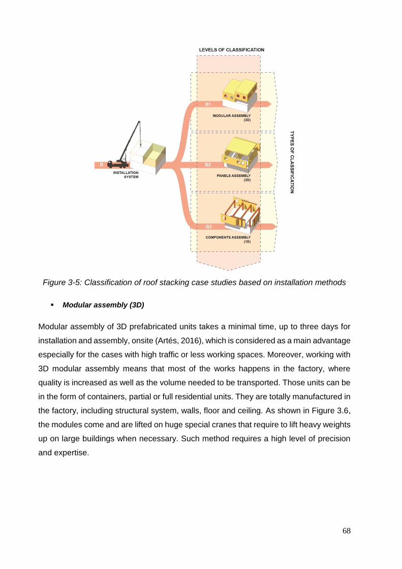
68
Figure 3-5: Classification of roof stacking case studies based on installation methods
Modular assembly (3D)
Modular assembly of 3D prefabricated units takes a minimal time, up to three days for
installation and assembly, onsite (Artés, 2016), which is considered as a main advantage
especially for the cases with high traffic or less working spaces. Moreover, working with
3D modular assembly means that most of the works happens in the factory, where
quality is increased as well as the volume needed to be transported. Those units can be
in the form of containers, partial or full residential units. They are totally manufactured in
the factory, including structural system, walls, floor and ceiling. As shown in Figure 3.6,
the modules come and are lifted on huge special cranes that require to lift heavy weights
up on large buildings when necessary. Such method requires a high level of precision
and expertise.
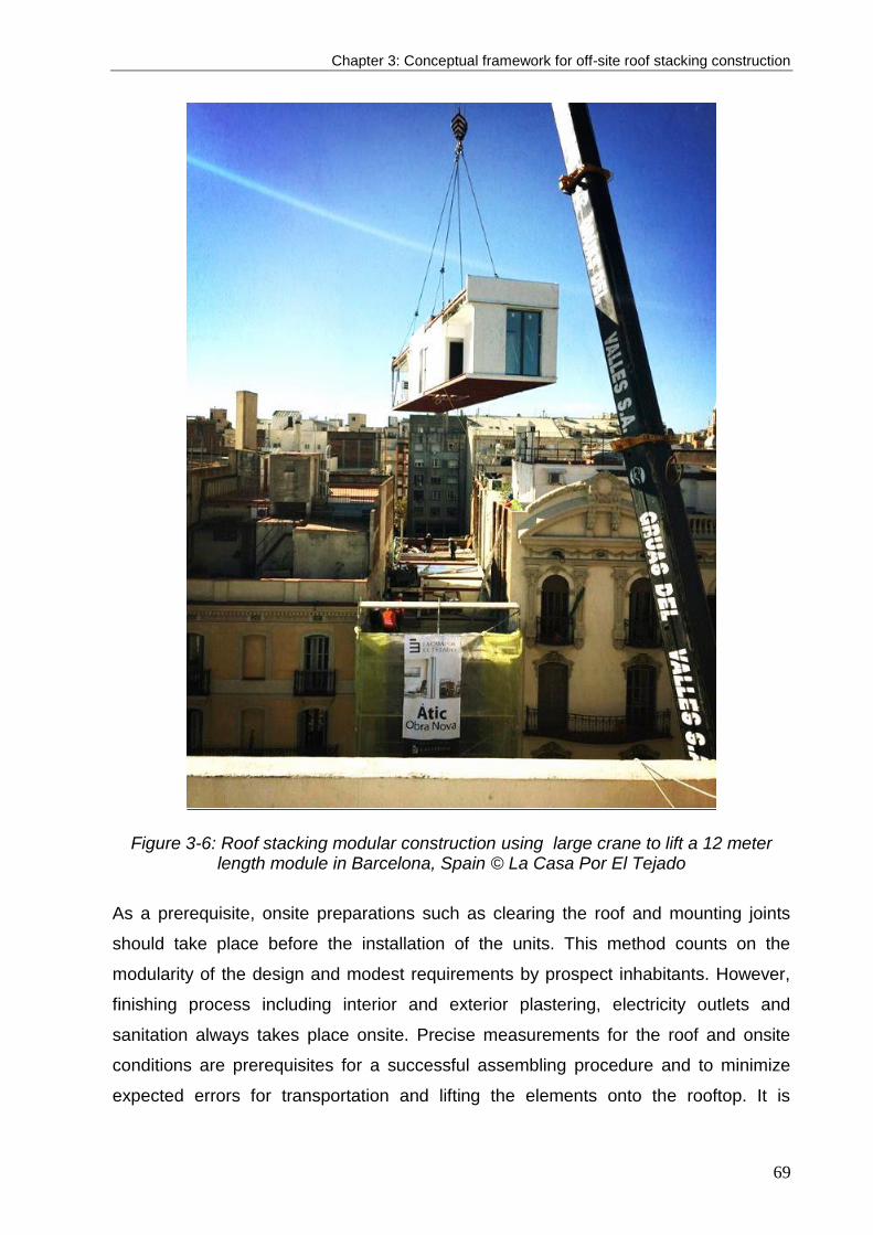
Chapter 3: Conceptual framework for off-site roof stacking construction
69
Figure 3-6: Roof stacking modular construction using large crane to lift a 12 meter length module in Barcelona, Spain © La Casa Por El Tejado
As a prerequisite, onsite preparations such as clearing the roof and mounting joints
should take place before the installation of the units. This method counts on the
modularity of the design and modest requirements by prospect inhabitants. However,
finishing process including interior and exterior plastering, electricity outlets and
sanitation always takes place onsite. Precise measurements for the roof and onsite
conditions are prerequisites for a successful assembling procedure and to minimize
expected errors for transportation and lifting the elements onto the rooftop. It is
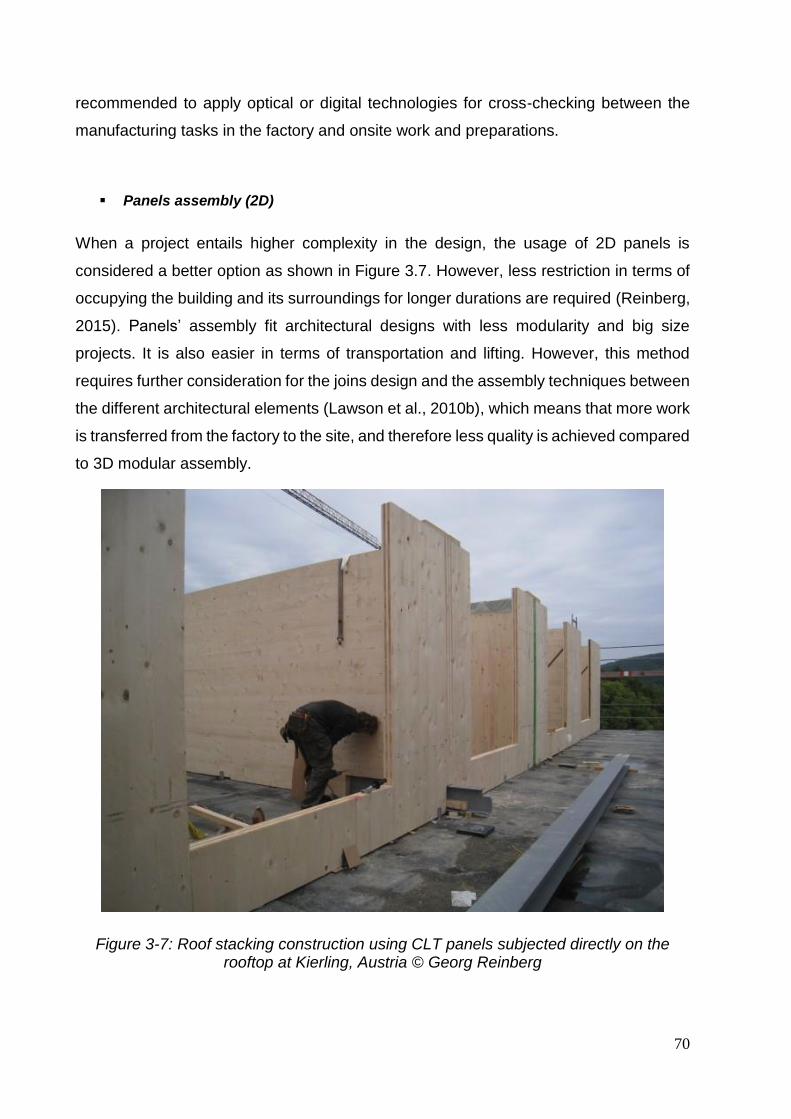
70
recommended to apply optical or digital technologies for cross-checking between the
manufacturing tasks in the factory and onsite work and preparations.
Panels assembly (2D)
When a project entails higher complexity in the design, the usage of 2D panels is
considered a better option as shown in Figure 3.7. However, less restriction in terms of
occupying the building and its surroundings for longer durations are required (Reinberg,
2015). Panels’ assembly fit architectural designs with less modularity and big size
projects. It is also easier in terms of transportation and lifting. However, this method
requires further consideration for the joins design and the assembly techniques between
the different architectural elements (Lawson et al., 2010b), which means that more work
is transferred from the factory to the site, and therefore less quality is achieved compared
to 3D modular assembly.
Figure 3-7: Roof stacking construction using CLT panels subjected directly on the rooftop at Kierling, Austria © Georg Reinberg

Chapter 3: Conceptual framework for off-site roof stacking construction
71
Components assembly (1D)
Components in this contexts would refer to beams, columns and frames. Components
assembly employ the usage of hybrid systems that include components together with
timber framing and fully modular sanitary compartments (Lawson et al., 2014). While,
the benefits of the onsite total construction and assembling prefabricated elements are
achieved, it still consumes more time than other methods. Some cases were recorded,
in which a total evacuation of the building from its inhabitants was not required (Lawson
et al., 2010b; Ruellan and Attia, 2015).
Figure 3-8: Roof stacking onsite elements' assembly (1D) using the existing couryard of the building in Brussels, Belgium © Antoine Galand
Building materials
Throughout the investigations made for roof stacking projects, it is found that existing
buildings with roof stacking cases were characterized by two different structural systems.
Buildings that return back to the nineteenth century and early twentieth century had load
bearing constructional system counting on the exterior massive walls, while buildings
from late twentieth century had skeleton structure out of reinforced concrete or steel
structure (Floerke et al., 2014). Building materials that have been involved in the process
of roof stacking for a structural purpose have been documented throughout the 136
different analyzed cases. Even though multiple materials have been listed, it was
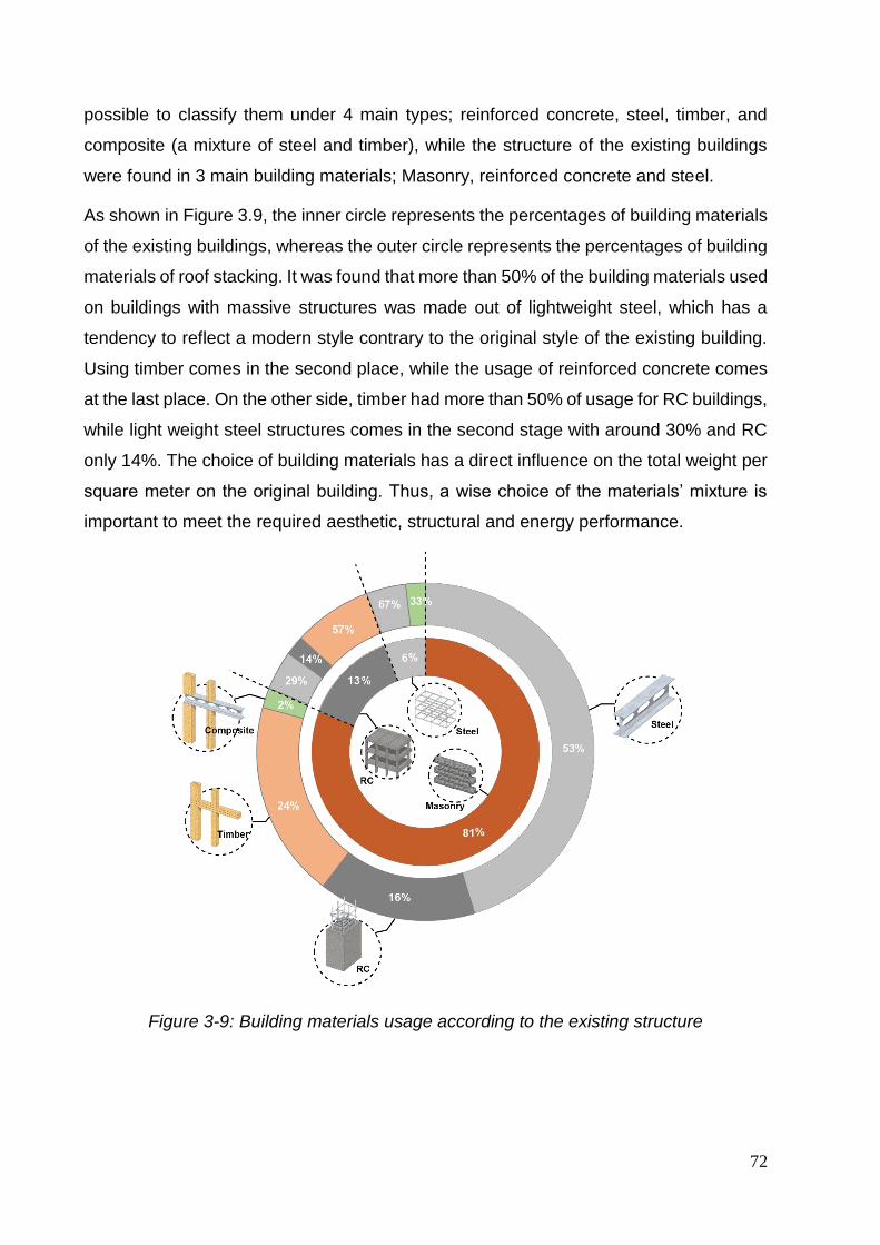
72
possible to classify them under 4 main types; reinforced concrete, steel, timber, and
composite (a mixture of steel and timber), while the structure of the existing buildings
were found in 3 main building materials; Masonry, reinforced concrete and steel.
As shown in Figure 3.9, the inner circle represents the percentages of building materials
of the existing buildings, whereas the outer circle represents the percentages of building
materials of roof stacking. It was found that more than 50% of the building materials used
on buildings with massive structures was made out of lightweight steel, which has a
tendency to reflect a modern style contrary to the original style of the existing building.
Using timber comes in the second place, while the usage of reinforced concrete comes
at the last place. On the other side, timber had more than 50% of usage for RC buildings,
while light weight steel structures comes in the second stage with around 30% and RC
only 14%. The choice of building materials has a direct influence on the total weight per
square meter on the original building. Thus, a wise choice of the materials’ mixture is
important to meet the required aesthetic, structural and energy performance.
Figure 3-9: Building materials usage according to the existing structure

Chapter 3: Conceptual framework for off-site roof stacking construction
73
It was not possible to list the construction weight of each case; however, some cases
were documented. The lightest weight for construction was found to be 80 Kg/m2 (Artés,
2016), that case claimed to be using timber construction for the structure and building
envelope. For other cases using lightweight steel construction materials, the total
construction weight ranged between 120 kg/m2 and 180 kg/m2 (Lawson et al., 2010b),
others were listed with 330 kg/m2 (Amer and Attia, 2017c; Artes et al., 2017, 2016).
Generally, for the best practice, it can be recognized as the lighter the better; however,
other considerations are involved to choose the most suitable materials as shown in the
previous mentioned criteria for load bearing and installation methods in addition to
design necessities, performance requirements, available technology and experience. As
a result, the choice of building materials is integrated in the choice of assembly method
within those categories. The decision making process of both sections is carried out
simultaneously, since they are highly dependent on each other with an overlap in the
decision making criteria, such as the weight and maximum span provided by the building
material, in addition to the availability of these materials and the manufacturer’s capacity.
The decision making on building materials includes the weight, maximum span provided
by the material, acoustic impedance, fire resistance, thermal performance and life cycle
assessment. Thus, by analyzing both parts together, a final decision could be made for
the type of the intervention and used building materials in addition to the exact number
of additional floors.
3.5. Roof stacking conceptual framework development
Framework overview
The development of this framework has been adopted from previous literature
concerned with decision making in construction in terms of developing a decision-
making framework (Han et al., 2018; Salama et al., 2017a), sustainable performance
criteria (Chen et al., 2010b), or the usage of timber construction (Ruellan and Attia,
2015). The framework is validated via real case studies and interviews with experts in
the field of off-site construction and roof stacking.
The conceptual framework for roof stacking construction is composed of two phases as
shown in Figure 3.10. Those phases are determined based on the earlier roof stacking
construction classification breakdown and onsite practices. In the first phase, a decision
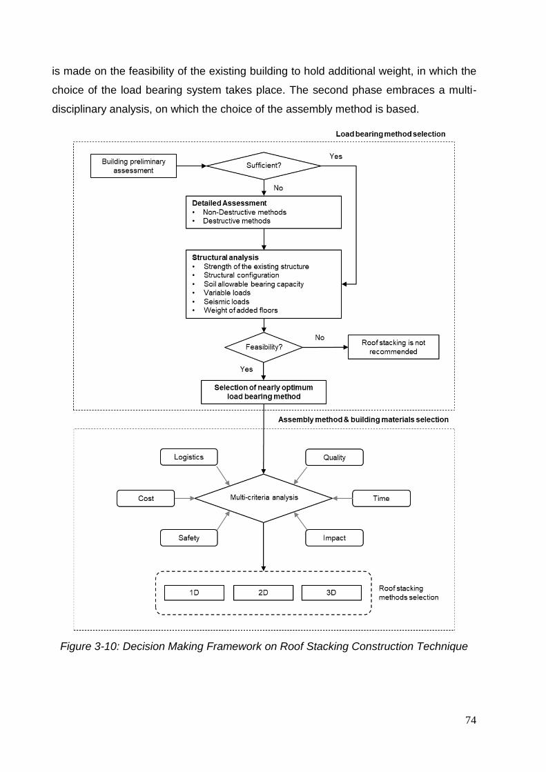
74
is made on the feasibility of the existing building to hold additional weight, in which the
choice of the load bearing system takes place. The second phase embraces a multi-
disciplinary analysis, on which the choice of the assembly method is based.
Figure 3-10: Decision Making Framework on Roof Stacking Construction Technique

Chapter 3: Conceptual framework for off-site roof stacking construction
75
Roof stacking conceptual framework
Load bearing method selection
The first phase of the conceptual framework is concerned with the selection of nearly
optimal load bearing method for roof stacking. A preliminary assessment could be
identified if there is enough data related to the structural strength and calculations of the
existing building. Otherwise, a detailed assessment is required for buildings that have
no sufficient documents or old enough to have alterations occurred in their structural
behavior over the time. Detailed assessment could be done by two methods: non-
destructive and destructive methods. More details on the assessment of existing
buildings are described in the ISO 13822:2010 (ISO 13822, 2010). A representative
workflow has been illustrated as well for the assessment process of the existing buildings
(Papageorgiou, 2016a). Non-destructive methods include sclerometric, acoustic,
radiological, electric and electromagnetic methods (L. Runkiewicz, 2009). Further
building diagnosis have been reviewed in details with identification the most suitable test
method according to the aim of investigation (Maierhofer et al., 2010). In most cases,
destructive methods are combined with non-destructive methods, which includes
extraction of concrete cylindrical specimens where characteristic compressive and
tensile strength are analyzed in the laboratory, or concrete adhesion pull-off test and
Rebar exposure, which is used to verify structural drawings or when there is no sufficient
information about existing reinforcement. At this stage, specialized civil engineers
produce a report that defines the strength of the existing building and decide whether
there is a need for additional reinforcement or not.
On this level, each of the strength of the existing building, structural configuration, soil
allowable bearing capacity, and the estimated loads of each variable loads, seismic
loads, and expected weight of the added floors are measured. By identifying the previous
attributes, it is necessary to conduct a feasibility study to determine whether it is feasible
to apply roof stacking or not. Feasibility measures on this level are concerned with
technical attributes. However, there are still inevitable constrains associated with roof
stacking projects such as urban regulations, social acceptance, and communication with
house owner, which may terminate the analysis process in early stages.

76
Table 3-1: Comparative analysis of different load bearing methods
Loading on Bearing Walls
Direct Loading In-Direct Loading
Be
st
Pra
cti
ce Old building with strong bearing walls
Narrow spans between bearing walls
Pramiary design requirements
Less requirement of the number of
added floors (Artes et al., 2017)
Large spans between bearing walls
Advanced design requirements
Less requirement of the number of
added floors
Pre
req
uis
ite
s
Ringbeam that bundles bearing walls &
ready to receive new loads (Floerke et
al., 2014)
Prefabricated frames or 2D elements
that vocer the span between existing
bearing walls
Steel joints in case of perpediculare
panels
Consider the added weight by the new
platform
Connect all bearing walls underneath
Define the position of the new loads
(Amer and Attia, 2017c)
Steel beams should comply with fire
safety regulation (Amer and Attia,
2017c)
Integrating the new reinforcements
according to the existing structure
(Lawson et al., 2010c)
Be
ne
fits
Does not require load redistributing
system
Reduces costs and usage of materials
Less time is needed for site
preparations
Higher acoustic performance
Flexibility in distributing load (futur
change of function)
Relatively lightweight distributing
system
Potential structural renovation of the
existing building
Dra
wb
ac
ks
Less flexiblity in terms of interior spaces
design
Less vareity in using building materials
and elements (should secure a self-
sustained structural stability)
Additional weight is only determined by
the actual strength of the existing
building
Additional weight is added Requires
more time
Additional costs
Less flexibility in distributing loads (no
opportunity of changing the design)
Requires additional sound insulation
(Artés, 2016)
May contribute in changing the internal
or extenral appearance of the building
(Lawson et al., 2010b)

Chapter 3: Conceptual framework for off-site roof stacking construction
77
Table 3.1 shows a comparative analysis between load bearing systems, on which the
best practices, prerequisites, benefits and drawbacks of each systems is explained. This
analysis is a cognitive process that takes place in the decision making process. As
mentioned in the previous section of this research, structural intervention is accustomed
to the need of the existing building; either the reinforcement includes soil, foundation,
columns, beams, slabs, walls or a combination of some of them (Papageorgiou, 2016a).
If the report shows that the building is strong enough to hold additional weight, there
would be no need to apply additional reinforcement, instead, one of the load bearing
methods are applied directly.
Assembly method selection
Once the decision on the load bearing system is defined, the phase of selecting the
assembly method, and respectively the most adequate building materials, takes place.
A multi-disciplinary attributed, in which the decision making process on assembly
method takes place, has been developed based on intensive review of literature
comprising over 40 publications in the field of building engineering, prefabrication,
modularity and off-site construction. (Akadiri et al., 2013; Amer and Attia, 2019a;
Arashpour et al., 2016, 2018; Basbagill et al., 2014; Blismas et al., 2006; Dind et al.,
2018; Eastman and Sacks, 2008; Goodier and Gibb, 2007a; Hosseini et al., 2018b;
Murtaza Mirza B. et al., 1993).
Those criteria have been categorized under the triple bottom lines of sustainability:
economic, social, and environmental in some literature (Chen et al., 2010a; Kamali and
Hewage, 2017). Others have categorized them differently, such as cost, health,
architecture, and environment (Legmpelos, 2013; Song Jongchul et al., 2005). However,
in this research, we propose a novel categorization based on the needs oriented towards
building on roof tops. This categorization is developed according to an early pilot survey
and questionnaire that has been conducted in three languages: English, French, and
Dutch, to collect more than 70 responses from experts in the field of roof stacking and
off-site construction. More information about the survey and questionnaires are
presented in Chapter 4. Table 3.2 shows a list of literature with related indicators, on
which the multi-disciplinary 6 categories are based. Those criteria are selected when
they at least found in two literature as shown in the table. The six factors are defined as
follows: cost, time, safety, quality, environment, and logistics. Cost factor includes
labors, building materials, transportation of building materials, maintenance and disposal
78
of construction wastes. Time factor includes the time needed for off-site manufacturing
and assembly (for 3D modules), assembly time needed and onsite as well, in addition
to the time needed to transport building materials, time intervals between tasks, and the
contribution of weather (i.e. weather can cause delays in the project timeline when more
tasks are handled onsite, compared to 3D modules that are completely assembled in
factory under a complete control of indoor weather). Safety factor includes the safety of
workers, the required number of workers on site, and the possibility of losing materials
on site. Quality factor includes the quality of the manufactures building components,
durability, flexibility of design and construction, integrity of added construction with
existing building, constructability, and the aesthetics of the added construction.
Environment factor includes the environmental impact (i.e. right to light / air, embodied
energy of the building materials, CO2 emissions, and energy efficiency of the added
construction), waste production of onsite materials, noise generation during the
construction, pollution produced onsite, water construction and fire resistance of the
building materials (e.g. which is also considered as a safety measure). Finally the
logistics factor includes dimensional constrains of building materials, availability of a
reliable supplier, availability of skilled labors, accessibility of building materials (including
cranes access) to working site and on the roof top, site disruption and management.
Thus, some analysis related to the context of the project are needed to be carried out,
including design complexity, street width, available cranes or transportation means,
traffic regulations, occupancy status of the existent building. Some of these criteria
overlap with the load bearing criteria; however, it comes in a later stage since the
determination of load bearing method has higher restrictions and priority when it comes
to initial feasibility studies. By the end of the second phase, a feasible study could be
carried out and determine if it is feasible to apply the project or not as there is a high
tendency to abort the project if it is not feasible. It is also important to mention that the
feasibility of the project should include the budget for any needed renovation for the
existing building (Amer and Attia, 2017c).

Chapter 3: Conceptual framework for off-site roof stacking construction
79
Table 3-2: Multi-disciplinary decision making attributes for assembly method and building materials
(Legmpelo
s, 2013)
(Chen et al., 2010
a)
(Kamali
and Hewa
ge, 2017)
(Kamali
and Hewa
ge, 2016)
(Idrus and Newman, 2002)
(Blismas
et al., 2006)
(Goodier and
Gibb, 2007
a)
(Jaillon and Poon, 2014)
(Song Jongchul et
al., 2005)
(Tam et al., 2007)
COST
Labor
Materials
Transportation
Maintenance
Disposal
TIME
Onsite - time
Offsite - time
transportation
Time intervals
Weather factor
SAFETY
Workers’ number
Workers safety
Materials loss
QUALITY
Components
Durability
Design flexibility
Integrative
Constructability
Aesthetic product
ENVIRONMENT
Impact
Waste production
Noise generation
Pollution
Water
Fire resistance
LOGISTICS
Dimensions
Supplier
Labor availability
Onsite efficiency
Accessibility
Site disruption
Site management

80
Framework validation loop
In order to create a validation feedback loop to the conceptual framework development
process, up to 10 case studies have been studied thoroughly. However, the interviews
do not represent a statistically representative sample, the interview process that started
since 2016 reached a saturation level by 2018. The criteria behind the selection of the
case studies are based on the constructional and geographical aspects. First, in terms
of the constructional aspect, case studies adopted different roof stacking assembly
method: modular, panels, and components assembly. The diversity in the load bearing
method has not been considered in the selection process to align with the third aim of
the breaking down process (locating the meeting points between the choice of load
bearing and assembly method). Second, in term of the geographical aspect, case study
are selected from different countries to support the universality in the development of
the conceptual framework.
The previously selected case studies have been investigated through semi-structured
interviews with the building engineers from several countries (e.g. Austria, Spain and
Belgium), who were responsible for the design and construction. By adopting the
concept of reverse engineering, the process of decision making, on which the selection
of roof stacking construction have been made, is broken down. The aim of the interviews
is to breakdown the decision making process on roof stacking construction methods
selection. Semi-structured interviews have been conducted, face to face, with each of
the building engineers. By interacting with every building engineer individually, there was
an opportunity to widely explain every project. Every interview lasted between 60 and
90 minutes, and followed by several emails to provide further information and feedback
loop, which was essential in the development of the conceptual framework. The
proposed questions were designed to target answers related to the three objectives,
previously mentioned, in the breaking down process. Three main points in the breaking
down process were essential to approve and validate the framework: (i) defining the
criteria on which the choice of load bearing method is based, (ii) evaluating the
consideration of the multi-disciplinary attributes when choosing assembly method and
building materials, (iii) locating the phase where the feasibility study is conducted, and
the meeting point between the choice of load bearing and assembly methods. More
information on the interviews are elaborated in the next chapter.

Chapter 3: Conceptual framework for off-site roof stacking construction
81
3.6. Discussion
This research is based on quantitative and qualitative methods of analysis based on
reviewing several projects around Europe, in addition to carrying out interviews with
buildings engineers. The results present a holistic portrayal of settings with an academic
and pragmatic focus. The data analysis is thematic with descriptive focus. Thus, the
pivotal strength of this research relies in its thorough investigation and review of projects
and interviewing different architects with different backgrounds. By reviewing the case
studies across Europe we could create a scope and identify patterns on roof stacking
construction techniques in the last 20 years. A preempt classification is established for
roof stacking construction in terms of building materials, bearing and installation
techniques rather than merely a modal one. This classification is a first step towards
strengthening the capacity to inform design and structural methods prior to decision
making for roof stacking in a systematic and structured way. This research represents
as well an inclusive reference for professionals in the field of architecture and building
construction with an interest in the field of urban densification and roof stacking using
lightweight construction.
Based on the classification, building materials analysis, and interviews, a guiding
framework has been established in this research. The classification analysis respond to
the research questions on the types of applied construction methods for roof stacking,
in addition to the criteria and the process of decision making. The decision making
framework takes in consideration several aspects; existing building strength capacity,
structural configuration, specification of available building material, in which a feasibility
study takes place. Finally, the urban context and neighborhood status that defines the
possible installation method and project implementation. We highlight the vital need to
increase the density through roof stacking in many European cities, such as Paris,
Brussels, Geneva, etc. We are not aware of any previous research that classified or
presented clear framework that supports the decision making of roof stacking
construction technique. Therefore, we find our work essential to provide a strategically
guidance for decision making. However, the availability of information was considered
to be a major challenge in this research resulting some limitations. The information
gathered from different literatures was not homogeneous, by which the studied sample
was not evenly classified. Accordingly, some cases were eliminated from the
classification process at certain parts and included in others.

82

Chapter 4: Identification of factors affecting the decision-making on roof stacking construction
83
4. Chapter Four: Identification of factors
affecting the decision-making on roof
stacking construction 3
The selection of optimum roof stacking construction method is merely based on
subjective evidence based on architects’ or owners requirements. Therefore, this
research aimed to identify the influential factors behind the selection and decision
making on roof stacking methods. An intensive review of literature, individual interview,
and pilot surveys has been carried out. A list of 37 factors has been identified based on
sustainability triple bottom line, i.e. environmental, economic, and social. A questionnaire
has been designed and distributed to architects and building engineers as active
stakeholders. The importance of the identified factors have been categorized and
ranked. The outcomes of this research draws the line to develop a new tool that
facilitates the construction of sustainable roofs in European cities.
3 This chapter is based on this article: Amer, M., & Attia, S. (2019). Identification of sustainable criteria for decision-making on roof stacking construction method. Sustainable Cities and Society, 47, 101456.

84

Chapter 4: Identification of factors affecting the decision-making on roof stacking construction
85
4.1. Introduction
Very few literature attempted to classify roof stacking methods, which is designated in
this research by the methods of bearing additional loads on the existing building from
one hand, and the methods of assembling additional roofs from the other hand. The
choice of building materials is also concerned in this study as a fundamental pillar in the
decision making process. As shown in the previous chapter, there are plenty of roof
stacking methods. In order to achieve the desired benefits from roof stacking, right
measurements and precautions have to be taken in consideration, especially during the
early phase decision making procedures. There is several literature that identifies
sustainability assessment measurements for new construction, renovation and
neighborhoods. However, when it comes to roof stacking there is a knowledge gap in
regards to the following:
- Definitive criteria for building on the rooftops, which secures the achievement of
the most benefits out of roof stacking while avoiding possible drawbacks.
- Relevant studies that identify factors on which for roof stacking methods are
chosen.
- Importance of each factor from the perspective of architects and building
engineers, who play an important role in the design and decision making process.
The aim and objectives of this study address the mentioned knowledge gaps.
Accordingly, the significance of this research lies in its aim to provide an approach
towards sustainable construction on the rooftops. In order to achieve this aim, this
research adopts three objectives. The first objective is to review sustainability criteria for
prefabricated, modular, dry construction and related fields in previous literature. The
second objective is to identify the influencing factors on the process of selecting specific
construction method particularly for roof stacking projects for residential buildings within
the European context. The third objective is to rank the importance of each factor in
relation with other factors in the decision making process from the perspective of
architects and building engineers.
It is important to mention that there is a high frequency of incorporating a full
modernization of the existing buildings on which roof stacking takes place. An overall
refurbishment is inevitably accompanied with an additional complexity in the decision

86
making process. This complexity has been addressed in several research in terms of
multi-objectivity, decision-making models, till incorporating low-carbon refurbishments
and energy efficiency targets (Alanne, 2004; Corrado and Ballarini, 2016; Juan et al.,
2009; Konstantinou and Knaack, 2013; Li et al., 2018).Therefore, this research opt to
focus on roof stacking related criteria to bring on an added contribution to the related
research gap on roof stacking. This study is a step towards achieving a holistic
sustainability for existing building and the new stacked roof.
This chapter consists of seven sections. A general introduction of this chapter is
presented in the first section, where roof stacking methods are identified by the mean of
load bearing and assembling techniques. The second section introduces and illustrates
the methodology of this research. In the third section, Decision-Making Factors (DMF)
for roof stacking are identified. A review is carried out on literature and previous research
work in related fields that cover modular construction and building materials resembles
in PPMOF (Prefabrication, Preassembly, Modularization and Offsite Fabrication).
Afterwards, a pilot survey and semi-structured interviews are carried out in this section
to finalize the outcome of the identified factors on this level. In the fourth section,
questionnaire design, targeted respondents and data analysis methods are discussed
and demonstrated. The results of this research are presented in the fifth section. This
section includes the analysis of the respondents, questionnaire validity, and the results
of the ranking analysis of the identified indicators. In the seventh and last section, the
conclusion of this research is drawn, giving highlights on the strengths, limitation and
recommended future work.
4.2. Methodology
The methodology in this chapter encompasses three different phases as shown in Figure
4.1. The first phase reviews the criteria that affect the decision making on choosing
construction methods and the choice of building materials are being identified. An
investigation has been carried out through a comprehensive review of literature. The aim
was to collect articles and group them, exploring factors linked to roof stacking
construction methods, and sustainable building materials. Afterwards, a pilot survey has
been carried out and semi-structured interviews have been conducted with different
architects and building engineers who are experienced with roof stacking projects. This

Chapter 4: Identification of factors affecting the decision-making on roof stacking construction
87
phase aimed to identify the most influencing factors on the decision making process and
to get an in-depth overview about roof stacking projects from practical perspective.
Figure 4-1: Research methodology diagram
A questionnaire in the second phase has been designed and surveyed to architects and
building engineers as the stakeholders who are actively involved in the decision making
process. The questionnaire has been designed in English, French and Dutch, to reach
the maximum number of respondents in Europe. The questionnaire has been
administered online and in a PDF format. Both methods have been used to ensure
receiving a wider range of responses. The questionnaire was delivered to more than 300
individuals, and followed by two reminder emails.. Moreover, researchers from the same

88
professional field were added to the targeted respondents to support the scientific and
rational contribution into the final results. The aim of this survey is to assess the
importance of each indicator.
In the third and last phase of this chapter, the robustness of the results are checked
through reliability analysis through Cronbach’s alpha. The aim of this reliability analysis
is to examine the internal consistency of the results, which have been ranked through
ranking analysis using Severity Index (SI). The ranking process assesses the
importance of each decision making indicator in relation to the other indicators. The
developed methodology in this chapter adopts similar strategies that established
sustainability criteria for sustainable building and construction method selection (Bhatt
et al., 2010; Chen et al., 2010a, 2010b; Cinelli et al., 2014; Idrus and Newman, 2002;
Rid et al., 2017; Soetanto R. et al., 2006). Given the special conditions of roof stacking
projects, a state of the art performance criteria have been identified that facilitates the
decision making process on selecting the most sustainable roof stacking construction.
4.3. Identification of Decision-Making Factors (DMF)
Previous studies and related criteria
A comprehensive review of literature in related areas has been carried out. Related
areas that cover assembly methods and building materials are resembled in PPMOF
(Prefabrication, Preassembly, Modularization and Offsite Fabrication). Modular
construction and comparisons between different construction methods and technologies
are also included in the review (Said et al., 2017; Salama et al., 2017b; Yuan et al.,
2018).
Idrus and Newman (2002) identified 29 factors that influence the decision making of
different floor construction systems. Those factors were perceived by a conducted
survey for several UK construction industry professionals and were categorized under
six categories, which are architectural, structural, constructional, operational,
environmental, and service. The study was limited to construction related factors that
counted 12 out of the 29 factors. (Goodier and Gibb, 2007b) provided an indication the
opinion of different sectors such as clients, contractors and engineers through
questionnaire survey. The outcomes of the questionnaire survey were summed up into
26 weighted factors. The factors are classified as advantages and barriers of offsite

Chapter 4: Identification of factors affecting the decision-making on roof stacking construction
89
construction method. One of the main critical factors of that study was skilled labors,
which was critical from the perspective of the contractors and suppliers.
Another study was conducted in the U.S., where Chen et al. (2010b) adopted the same
methodology. A total of 33 sustainable performance criteria have been developed for
construction method selection in concrete buildings. Those criteria have been
categorized based on the triple bottom line of sustainability which are: economic, social
and environmental aspects. The study rated and further analyzed the developed criteria
through conducting a wide survey to industrial practitioners in the field of construction.
Kamali and Hewage (2017) adopted the same results of the 33 sustainable performance
criteria and categorized them differently under the same triple bottom line of
sustainability. Jaillon and Spoon (2008) conducted a comparison between different
sustainable construction aspects in dense urban environment of Hong Kong. The
comparison was made on the same triple bottom line of sustainability: economic,
environmental, and social aspects for 13 different categories. The comparison was
based on industry questionnaire survey in addition to detailed case study analysis.
Another survey in the same area comparing between different constructions methods
with a focus on waste generation and management has been conducted. Tam et al.
(2007) categorized 17 advantages and disadvantages of constructional aspects in the
comparative analysis. Important findings related to cost and site supervision were
highlighted as key factors in the whole construction process.
Legmpelos (2013) adopted a decision making method named “Choosing by Advantage”
CBA to choose between three different construction methods. 19 different factors that
influence the decision making were identified under 6 categories: Location, time, quality,
safety, weather and project’s characteristics. Even though cost criterion was not set
directly as an influential factor in that study, it has been mentioned under the “hidden
cost” term. Hidden cost term referred to the negative cash flows, as a result of the
difficulty to predict them. Thus, the light is shed over the factors that concern hidden cost
and their influence on the whole decision making process. Similar differentiation
between what so called the hidden cost and major cost has been mentioned in another
research. Blismas et al. (2006) showed that different case studies demonstrated the
evaluation on direct material and labor cost, while disregarding other cost related items
such as site facilities, crane use and rectification of works. Song et al. (2005) divided the
decision making process into two levels. The first level identifies the feasibility of the

90
project, while the second level assess the construction in details, which corresponds to
10 categories. The 10 categories included time, cost, labor, safety, site attributes,
contract types, design, transportation, supplier capacity, in addition to the mechanical
system capacity.
As shown in the literature review, findings from the previous studies proposed several
factors and criteria of decision making. In this research, criteria and factors related to
construction parameters were only selected. Other criteria related to end user
satisfaction, social acceptance or local market, are not selected unless it affects the
constructional process. However, due to the special conditions of roof stacking projects,
further interview and pilot survey has been conducted to assess the findings and to
identify further factors that influence the decision making on roof stacking method.
Interview and pilot survey
In order to get in-depth overview on roof stacking projects from a practical point of view,
several interviews have been conducted with three architects from three different
countries. The interviews were based on semi-structured questionnaire. In this type of
questionnaire, each architect had the flexibility to comprehensively explain their projects.
The architects were selected based on the diversity in geographical context, the type
and diversity of the implemented project. Each of the previously described methods of
roof stacking were used in the investigated projects. Moreover, some of the interviewed
architects have experience with multiple roof stacking projects. For instance, one of the
architects has implemented more than 10 cases. Throughout the interviews, it was
possible to identify the criteria and process of the decision making from a practical point
of view.
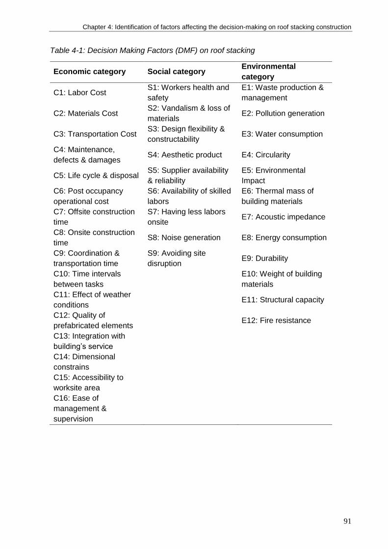
Chapter 4: Identification of factors affecting the decision-making on roof stacking construction
91
Table 4-1: Decision Making Factors (DMF) on roof stacking
Economic category Social category Environmental
category
C1: Labor Cost S1: Workers health and
safety
E1: Waste production &
management
C2: Materials Cost S2: Vandalism & loss of
materials E2: Pollution generation
C3: Transportation Cost S3: Design flexibility &
constructability E3: Water consumption
C4: Maintenance,
defects & damages S4: Aesthetic product E4: Circularity
C5: Life cycle & disposal S5: Supplier availability
& reliability
E5: Environmental
Impact
C6: Post occupancy
operational cost
S6: Availability of skilled
labors
E6: Thermal mass of
building materials
C7: Offsite construction
time
S7: Having less labors
onsite E7: Acoustic impedance
C8: Onsite construction
time S8: Noise generation E8: Energy consumption
C9: Coordination &
transportation time
S9: Avoiding site
disruption E9: Durability
C10: Time intervals
between tasks
E10: Weight of building
materials
C11: Effect of weather
conditions E11: Structural capacity
C12: Quality of
prefabricated elements E12: Fire resistance
C13: Integration with
building’s service
C14: Dimensional
constrains
C15: Accessibility to
worksite area
C16: Ease of
management &
supervision

92
Afterwards, a first draft for the decision making factors has been designed based on the
review of literature. However, in order to validate those indicators, a pilot survey has
been distributed among 10 architects and building engineers with various backgrounds
in academia and practice. The interviewees were given the task to do three things: (i)
provide a feedback on the structure of the criteria and their relevance to each category
that has been assigned for. (ii) Provide further suggestions and modifications on the
given criteria pointing out what is relevant and what is not. (iii) Answer and review the
questionnaire before launching a wide survey. The pilot survey was stopped after 10
interviewees, this is when a repetition has been found in the answers from the experts.
According to the received feedback from the pilot survey and interviews, the identified
DMFs have been refined and categorized under the triple bottom line of sustainability,
i.e. environmental, economic, and social as shown in Table 4.1. The final outcome was
used to develop the final questionnaire and launching the survey, which is described in
details in the following section.
4.4. Questionnaire design and surveying
Based on the literature review, primary factors were identified and categorized as shown
in the previous section in this chapter. The factors have been further refined and modified
according to a pilot survey and individual interviews with practitioners who have
expertise in roof stacking projects. Based on the identified indicators, a survey has been
conducted on a broader scale. The aim of this survey is to investigate the importance of
each indicator from the point of view of a wide range of practitioners.
Questionnaire design and targeted respondents
The questionnaire has been designed in three languages: English, French and Dutch.
Those language were necessary to reach the maximum number of respondents around
Europe and Belgium specifically. Afterwards the questionnaire has been administered
in two different formats: online and PDF format. The online survey platform saved more
time because it did not require a second contact between the surveyor and respondents.
Yet, both methods have been used to ensure receiving a wider range of responses.
The questionnaire is divided into eight sections. The first section aimed to provide basic
information about the respondent, such as their experience, number of roof stacking
Chapter 4: Identification of factors affecting the decision-making on roof stacking construction
93
projects they have been involved in, and the methods used in construction. The other
seven sections included the decision making criteria, in which the respondents were
asked to rank the level of importance of every indicator on a scale of 1 to 5. The scale
of 1 represents the least important while the scale of 5 represents the most important.
Respondents were encouraged to add more criteria based on their experience and point
of view. Added criteria were amended and integrated with the given list to generate more
comprehensive and inclusive performance criteria for roof stacking. The definitions of
the factors were attached with the questionnaire for guidance and clarification whenever
is needed by the respondent.
In this type of projects, targeted respondents or stakeholders who are concerned with
roof stacking are defined under two types: active and passive stakeholders. Active
stakeholders are those who actively participate in the construction process of roof
stacking and selection of construction method and building materials, such as architects,
engineers, and contractors. While passive stakeholders are those who are affected by
the construction or the construction process of roof stacking, such as the owner and
neighbors. Each type of stakeholders has different interests and priorities. Since only
construction related factors were considered in the development and ranking of decision
making factors, this research has been studied from the point of view of the active
stakeholders, specifically architects.
The questionnaire has been administered in several ways. The first way was by directly
sending to a contact list of architects. Those contacts have been gathered during the
early investigations into roof stacking case studies. Further, the questionnaire has been
indirectly distributed through building and construction institutions who were present
during the Batibouw Expo, the largest building and construction exhibition in Belgium
that takes place once a year hosting more than 300,000 visitors. The contacted
institutions includes but limited to the architectural chamber in Belgium, both Order des
Architectes for Wallonia region French speaking community and Orde van Architecten
for the Dutch speaking community in Flanders. Lastly, the questionnaire has been
distributed through the mailing list and social media of the academic institution
represented in the University, which contains contacts of academics and researchers
from the field of engineering and construction.
94
Data analysis methods
The main aim of this survey is to identify the level of importance of each criterion rather
than quantifying the importance of the factors between each other. In order to conduct
ranking analysis for the given indicators, non-parametric statistics has been used
(Johnson and Bhattacharyya, 2014) rather than parametric statistics such as means,
standard deviation, etc. as it wouldn’t produce meaningful results (Chen et al., 2010a;
Idrus and Newman, 2002). The non-parametric analysis that has been adopted in this
research is by using severity index as shown in Equation (4.1).
Severity Index (SI) = ∑ 𝑤𝑖 .
𝑓𝑖
𝑛 5
𝑖=1𝑎
⁄ (%) (4.1)
Where 𝑖 represents the point given to each criterion by the respondent, which range from
1 to 5. The 𝑤𝑖 represents the weight of each criterion that takes a rating score from 1 as
the lowest and 5 as the highest. 𝑓𝑖 is the frequency of the point 𝑖 by all the total number
of respondents that is represented by 𝑛. Finally 𝑎 represents the highest weight which
is equal to 5. The resulted values of the severity index may range between 0 the lowest
and 1 the highest.
Reliability analysis has been further conducted to ensure that the criteria are consistent.
Alpha reliability coefficient, named as Cronbach’s alpha, produces a value between 0
and 1. The greater the value the more internal consistency it achieves. In order to
calculate Severity Index, frequency analysis was carried out to obtain the rating
percentages of every criterion. Severity Index analysis was adopted in this research to
arrange the factors according to their relative importance.
4.5. Results
Respondents’ analysis
The questionnaire was delivered to a population sample of 327 individuals. A number of
two follow up reminder emails have been sent to those who did not respond from the
first time. As shown in Table 4.2, a total of 78 valid responses out of 327 calls have been
received. Among those responses, 60 responses were professional architects and
building engineers, whereas 18 were from building engineers from the researcher
department and professors in the field of building and construction. Architects and

Chapter 4: Identification of factors affecting the decision-making on roof stacking construction
95
building engineers from several European countries have contributed in this survey, with
a majority responses from Belgium, Austria and Germany. Respondents’ experiences
varied. Around 30% of the respondents have less than 5 years’ experience, 32% have
more than 25 years’ experience, and 38% have experience that ranges between 5 and
25 years. A pie chart visually represents the results of their experiences as shown in
Figure 4.2.
There have been variations in the number of roof stacking projects in which respondents
have been involved. As shown in Figure 4.3, about 41% have an experience of less than
two projects, which means that they may have not been involved in such many projects.
However, we made sure that every survey respondent has participated in at least one
project. Therefore, their responses were important since they are targeted active
stakeholders meant to take decision when involved in such projects. Whereas 30% of
the respondents have experience with a number between 2 and 5 roof stacking projects,
17% have experience with 6 to 10 roof stacking projects, and finally 12% have
experience with more than 10 roof stacking projects. When we opted to distinguish long
experienced (>25 years) and short experienced (<5 years) participants, we did not
identify a significant difference. Therefore, there was no consideration made for the
difference between respondents’ experiences. Even though the lack of distributing the
questionnaire to more individuals from other European countries is considered a
limitation to this research, the diversity in the responses in terms of country, years of
experience, and involvement in roof stacking projects guarantees obtaining a holistic
evaluation.
Table 4-2: Questionnaire response rate
Contact method Distributed
questionnaires
Valid
responses Response Rate (%)
Direct emails 114 55 48%
Indirect emails 213 23 10.7%
Total 327 78 23.8%

96
Figure 4-2: Percentage of respondent's years of experience
Figure 4-3: Respondents experience with roof stacking projects
Questionnaire validity
Even though the response rate has reached 23.8% from the total number of distributed
questionnaire, several measurements are taken in consideration, such as sample size
calculation and reliability analysis, to insure the validity of the responses. The results are
measured based on a quantitative continues variables, contrary to categorical set of
data. A sample size and correction formulas were calculated to determine the proper
sample size using a confidence level and acceptable margin of error equivalent to 95%
and 5% respectively (Bartlett et al., 2001; Kamali and Hewage, 2017; William G.
Cochran, 1977). Accordingly, the total number of respondents is adequate to extract
valid results.
Another test is carried out which is called reliability analysis. This analysis refers to the
level to which the questionnaire produces valid results by examining its internal
consistency. Reliability coefficient is determined by Cronbach’s alpha, the most
commonly used measurement for questions with Likert scale type of answers. Alpha
reliability coefficient ranges between 0 and 1. A minimum coefficient threshold of 0.7 is
required to insure internal consistency of the questionnaire (Lance et al., 2006; Nunnally,
1978). The higher the value, the more consistence it is. By using SPSS statistics
software, Cronbach’s alpha is measure for each category as shown in Table 4.3. All
categories achieved reliability values more than 0.8, which shows a strong internal
consistency for each category and the whole questionnaire.
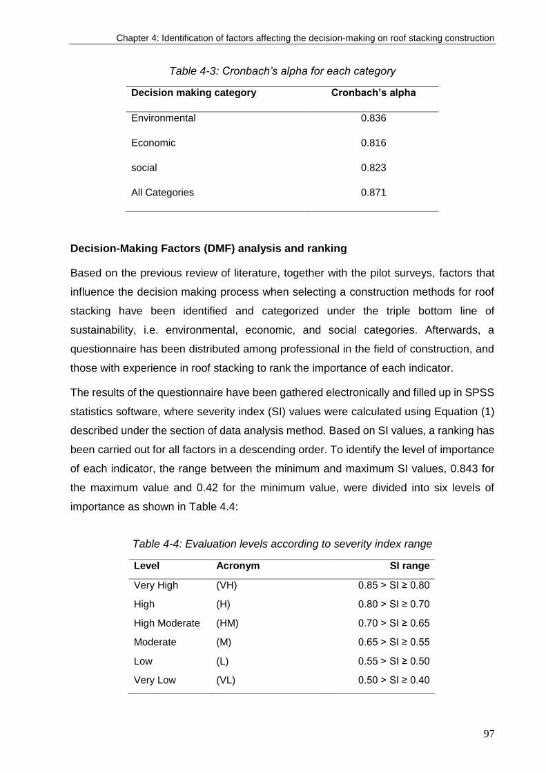
Chapter 4: Identification of factors affecting the decision-making on roof stacking construction
97
Table 4-3: Cronbach’s alpha for each category
Decision making category Cronbach’s alpha
Environmental 0.836
Economic 0.816
social 0.823
All Categories 0.871
Decision-Making Factors (DMF) analysis and ranking
Based on the previous review of literature, together with the pilot surveys, factors that
influence the decision making process when selecting a construction methods for roof
stacking have been identified and categorized under the triple bottom line of
sustainability, i.e. environmental, economic, and social categories. Afterwards, a
questionnaire has been distributed among professional in the field of construction, and
those with experience in roof stacking to rank the importance of each indicator.
The results of the questionnaire have been gathered electronically and filled up in SPSS
statistics software, where severity index (SI) values were calculated using Equation (1)
described under the section of data analysis method. Based on SI values, a ranking has
been carried out for all factors in a descending order. To identify the level of importance
of each indicator, the range between the minimum and maximum SI values, 0.843 for
the maximum value and 0.42 for the minimum value, were divided into six levels of
importance as shown in Table 4.4:
Table 4-4: Evaluation levels according to severity index range
Level Acronym SI range
Very High (VH) 0.85 > SI ≥ 0.80
High (H) 0.80 > SI ≥ 0.70
High Moderate (HM) 0.70 > SI ≥ 0.65
Moderate (M) 0.65 > SI ≥ 0.55
Low (L) 0.55 > SI ≥ 0.50
Very Low (VL) 0.50 > SI ≥ 0.40

98
Categorizing the results into six levels, three main levels in two sets each, help to set up
a weighing factor for each indicator. Weighing factor does not quantify the importance
difference between each indicator to the other, it rather identifies the level of importance
of each indicator. The three main levels of evaluation are as following: High, Medium,
and Low. While the secondary grading is given under each level to identify the indicator
with the higher importance. For instance, “High” level is graded into “Very High” and
“High”, giving higher importance to those factors with SI equal of more than 0.70. While
“Moderate” is graded into “High Moderate” and “Moderate”, and lastly the “Low” level is
graded into “Low” and “Very Low” respectively. The results of the ranking analysis are
presented in Table 4.5. There are 6 factors found to have the highest priority among
architects with a “Very High” rank. Those factors are followed by 9 factors ranked as
“High”, 5 factors ranked as “High Medium”, 8 factors ranked as “Medium”, 7 factors
ranked as “Low”, and only 2 factors which have the lowest priority and ranked as “Very
Low”.
Table 4-5: DMF for roof stacking construction methods and ranking analysis
Decision-Making Factors (DMF) Valid percentage for score of (%) Severity
index
Overall
Ranking
Imp.
Level 1 2 3 4 5
C12: Quality of prefabricated elements 0.0 1.7 15.0 43.3 40.0 0.843 1 VH
E8: Energy consumption 0.0 1.7 18.3 38.3 41.7 0.840 2 VH
S1: Workers health and safety 0.0 1.7 15.0 48.3 35.0 0.833 3 VH
E10: Weight of building materials 0.0 6.7 15.0 35.0 43.3 0.830 4 VH
E9: Durability 0.0 5.0 20.0 31.7 43.3 0.827 5 VH
E11: Structural capacity 0.0 1.7 20.0 43.3 35.0 0.823 6 VH
C8: Onsite construction 0.0 5.0 23.3 41.7 30.0 0.793 7 H
S6: Availability of skilled labors 0.0 0.0 25.0 56.7 18.3 0.787 8 H
S4: Aesthetic product 1.7 5.0 23.3 40.0 30.0 0.783 9 H
C1: Labor cost 0.0 5.0 30.0 41.7 23.3 0.767 10 H
E1: Waste production & management 0.0 5.0 26.7 53.3 15.0 0.757 11 H
C2: Materials cost 0.0 11.7 28.3 45.0 15.0 0.727 12 H
E5: Environmental Impact 0.0 13.3 26.7 46.7 13.3 0.720 13 H
S5: Supplier availability, location & reliability 0.0 5.0 46.7 31.7 16.7 0.720 14 H
E7: Acoustic impedance 0.0 13.3 33.3 43.3 10.0 0.700 15 H
C6: Post occupancy operational cost 5.0 8.3 36.7 43.3 6.7 0.677 16 HM
E12: Fire resistance 3.3 13.3 38.3 35.0 10.0 0.670 17 HM
C14: Dimensional constrains 1.7 23.3 36.7 16.7 21.7 0.667 18 HM
C13: Integration with existing building’s service 6.7 15.0 33.3 30.0 15.0 0.663 19 HM
C15: Accessibility to worksite & storage area 0.0 18.3 45.0 25.0 11.7 0.660 20 HM
S7: Having less labors onsite 1.7 15.0 55.0 25.0 3.3 0.627 21 M
E6: Thermal mass of building materials 1.7 26.7 36.7 28.3 6.7 0.623 22 M
C11: Effect of weather conditions 5.0 23.3 38.3 26.7 6.7 0.613 23 M
S3: Design flexibility & constructability 8.3 20.0 41.7 21.7 8.3 0.603 24 M
E4: Circularity 10.0 23.3 38.3 20.0 8.3 0.587 25 M
C10: Time intervals between tasks 5.0 30.0 41.7 18.3 5.0 0.577 26 M

Chapter 4: Identification of factors affecting the decision-making on roof stacking construction
99
C3: Transportation cost 3.3 35.0 43.3 15.0 3.3 0.560 27 M
C5: Life cycle & disposal cost 11.7 28.3 30.0 28.3 1.7 0.560 28 M
S9: Avoiding site disruption 3.3 36.7 41.7 15.0 3.3 0.557 29 L
E2: Pollution generation 5.0 35.0 40.0 16.7 3.3 0.557 30 L
C9: Coordination & transportation time 6.7 31.7 43.3 15.0 3.3 0.553 31 L
C4: Maintenance, defects & damages 13.3 28.3 38.3 16.7 3.3 0.537 32 L
C16: Ease of site management & supervision 15.0 33.3 31.7 8.3 11.7 0.537 33 L
S8: Noise generation 8.3 33.3 45.0 11.7 1.7 0.530 34 L
C7: offsite construction time 13.3 41.7 26.7 8.3 10.0 0.520 35 L
E3: Water consumption 26.7 26.7 30.0 11.7 5.0 0.483 36 VL
S2: Vandalism & loss of materials 33.3 30.0 30.0 6.7 0.0 0.420 37 VL
In contrary, there are two factors that represented the least priority to architects, which
are the water consumption, from an environmental perspective, and vandalism of
building materials, from a safety perspective. The reason behind that has to do with the
nature of roof stacking, which uses dry construction methods. This method does not
require the usage of water onsite as a basic need in the construction process. The aspect
related to “vandalism and loss of material” reflects the fact that an evidence of losing
materials due to either vandalism is not common or architects did not experience
vandalism as a common problem in construction, therefore it has a negligible
consideration.
From the “Quality category”, the first and fifth factors are found to be “quality of
prefabricated elements” and “durability” respectively, which is reasonable when
evaluating the factors from the point of view of an architect. Both factors came as a
priority to “availability of skilled labors” and “supplier availability, location & reliability”
which were ranked as only “high”. From the environmental category, the “energy
consumption” ranked the second among all indicators, whereas “waste production and
management” is found to be ranked as “High”. None of the factors from the cost category
are ranked as “Very High”. Only “labor” and “materials cost” are ranked as “High”. The
budget does not represent the major concern by architects, which is different from the
owner or the manufacturer. However, they were still ranked as “High” since they
represent a major limitation in the overall design and construction.
Cost and time factor
Cost has been a common project driver for the selection process of construction
methods and building materials. The cost associated with transportation and lifting,
maintenance, lifecycle and post occupancy are added to the cost related concerns in the

100
decision making process, which raises the cost per unit area between 5 – 20% compared
to onsite construction methods (Hsieh, 1997). However, not all cost related factors
possess the same importance. As shown in Figure 4.4, labor cost has the highest priority
followed by the cost of building materials, which are ranked as “High”. However, when
compared to the other indicators, they do not possess the highest priority to architects.
This is due to the fact that cost represents a higher concern to clients who owns the
budget and contractors or manufacturers who provides the materials and labors as
proven by previous research (Chen et al., 2010a; Idrus and Newman, 2002; Kamali and
Hewage, 2017). Accordingly, the given high priority for building materials and labor costs
are mainly driven from clients’ demand on having the highest quality with lower prices.
The cost related to post occupancy operation represents the third priority in the cost
category, which is strongly linked to the indoor thermal and energy performance of the
building (Attia, 2018b). Post occupancy associated cost is an indicator of the
environmental quality of the given design configurations, therefore it represents a “High
Medium” importance to the architects. Whereas the costs associated with transportation,
life cycle and maintenance got the least priority in the cost category. Given that
transportation cost only may contribute up to a 15% increase in the overall cost of
construction (Hsieh, 1997), there are several reasons that explains why transportation
cost has not been given a high priority when choosing construction method. The first
reason is related to the scale of the targeted projects, which are non-complex residential
projects, do not highly causes a variation in the transportation cost and therefore the
overall construction cost. Small scale projects do not require additional number of
truckloads used for building materials delivery or special cranes for lifting up heavy
materials. These conditions do not comply with transporting 3D modules, which requires
from one hand advanced delivery and lifting settings, but on the other hand it significantly
reduces the cost associated with time consumption and multiple transportation. The
second reason is because transportation cost lies under the hidden costs (Legmpelos,
2013). Hidden costs are hard to be predicted in the overall cost estimations for small
projects, and that explains why transportation cost are not strongly considered in roof
stacking decision making process. The same reason applies for lifecycle and
maintenance costs, which are associated with a high level of uncertainty (Blismas et al.,
2006; Goodier and Gibb, 2007b).
Chapter 4: Identification of factors affecting the decision-making on roof stacking construction
101
The importance of time related factors varies from one project. The variance depends
on clients’ requirement on the first phase followed by the method of construction. For
instance, the assembly of 3D modules have shown the highest efficiency when it comes
to required onsite construction time (Amer and Attia, 2017c; Artes et al., 2017).
Moreover, the speed of construction has a direct effect on the cost (Jaillon and Poon,
2008). This importance is obvious in the ranking analysis in the time category as shown
in Figure 4.4. Among time related indicators, onsite construction time is found to have
the highest priority to architects in the decision making process given a “High” ranking.
Associated tasks that adds to the overall construction time such as the effect of weather
conditions, time intervals between different tasks, coordination and transportation time
range between being “High Medium” and “Medium”. Whereas the time needed for pre-
construction phase does not resemble a priority to the architects. Previous research
found that appropriate periods of coordination between different stakeholders such as
architects, contractors, and suppliers are necessary to achieve a high quality end
product (Chen et al., 2010a), which resembles the highest priority of an architect.
Accordingly, the overall time related factors has the least priority as an average
compared to other categories.
Safety and quality factors
In this category, three aspects are considered. The first aspect consider workers’ safety
from dangerous tasks and, for instance, the usage of toxic materials. The second aspect
consider the safety of occupants by providing a safe construction. The third aspect is
related to security in construction site from vandalism. As shown in Figure 4-4, three
factors out of five where ranked as “Very High” in the safety category, which are workers’
health and safety, weight of building materials, and their structural capacity. Even though
workers’ safety and health does not lie directly under the responsibilities of architects, it
has been identified as a top priority. In contrary with previous research, workers’ health
and safety did not occupy high importance. The interpretation of this finding is related to
the actual risk that workers’ have on site. Risk analysis and safety instructions lie fully
under the responsibility of contractors. Given that workers’ safety is a top priority, unless
construction process includes dangerous tasks, workers’ safety would not influence the
selection process of construction method. Whereas, the selection of building materials
and structural design strongly lies within the hands of the architects. Since roof stacking
projects counts on the capacity of the existing building to hold more weight, total weigh

102
of construction is very important. Structural design represents a common challenge for
roof stacking projects. Accordingly, the weight of building materials and their structural
capacity are ranked as “Very High” and affects the construction method selection
process.
Fire resistance is ranked as “Medium High” after the structural capacity of building
materials. Interviews with architects revealed that they follow well known solution to
increase the fire resistance of building materials by coating, cladding or increasing
elements section in case of timber construction. Moreover, firefighting measures has
strict specifications by local and Euro-codes that has to be followed for each project,
therefore it does not severely interfere in the decision making process. The last and least
important of all factors were found to be the vandalism of building materials, which has
been given a “Very Low” priority.
Quality related factors were found to have the average highest priority to architects when
selecting construction methods for roof stacking. The quality of the prefabricated building
elements and their durability possess “Very High” rank, followed by acquiring aesthetic
product which is ranked as “High”. Fortunately, it is easier to achieve high quality building
materials in this type of construction compared to conventional onsite construction, since
roof stacking relies on the usage of prefabricated building elements. The usage of
prefabricated elements have several advantages given the climate-controlled
environment where prefabrication is taking place. Moreover prefabrication plants have
stricter quality control measures than that of the onsite construction (Jaillon et al., 2009;
Jaillon and Poon, 2008). These conditions secures less damages, defects and
associated disposal costs, which comes in favor of all stakeholders. The quality in terms
of integrating with existing building’s services got a “High Medium” priority, while design
flexibility and constructability got a “Medium” priority. Through interviews, it has found
that those factors do not resemble a great challenge in most projects. Integration of roof
extensions to existing buildings does not highly influence the choice of construction
method, it rather requires higher consideration for MEP and HVAC engineers.
Environmental and logistical factors
The importance of the environmental factors is strongly attached to the level of
awareness and responsibility towards global warming, greenhouse gases and overall
environmental impact from one hand, and the onsite and indoor impact from the other

Chapter 4: Identification of factors affecting the decision-making on roof stacking construction
103
hand. As shown in Figure 4.4., the highest priority is given to the energy consumption
among the environmental related factors with a “Very High” ranking, and has got the
second priority to the overall ranking analysis. Energy consumption is followed by waste
production and management, environmental impact, and acoustic impedance with a
“High” level of importance. Afterwards thermal mass and circularity of building materials
are given “Medium” level of importance, even though circularity, in terms of circular
economy and construction, has gained an interested in the sector of construction (Denis
et al., 2018; Galle & De Temmerman, 2016; Romnée, Vandervaeren, Breda, & Temmerman, 2019).
Onsite pollution and noise generation are given “Low” importance, while water
consumption got “Very Low” importance and lies in the bottom of the ranking analysis.
The reason behind the importance of achieving energy efficient buildings returns back
to the new regulations enforced by the EU that requires all new construction should be
nearly Zero Energy Buildings (nZEB) according to the Energy Performance of Building
Directive (EPBD) (Boermans et al., 2015). Therefore, the majority of the architects have
rated the energy consumption within their highest priorities. Energy efficient buildings
are achieved by either delegating the calculation to specialized consultancies, or by
simply following local codes and regulations that secures a minimum energy
consumption per square meter. This finding contrasts with previous research, in which
energy consumption did not achieve high ranks. The main reason behind this
contradiction is a result of the difference in the targeted respondents (Kamali and
Hewage, 2017) or the date in which the survey was carried out (Chen et al., 2010a).
In total, there are 9 factors that are strongly related to the selection of building materials
within the assembly methods determination. The factors are listed as following:
- (C12) Quality of prefabricated elements SI: 0.84 “Very High”
- (E10) Weight of building materials SI: 0.83 “Very High”
- (E11) Structural Capacity SI: 0.82 “Very High”
- (C2) Material cost SI: 0.73 “High”
- (E5) Environmental Impact (of materials) SI: 0.72 “High”
- (E7) Acoustic impedance SI: 0.70 “High”
- (E12) Fire resistance SI: 0.67 “Moderate”
- (E6) Thermal mass of building materials SI: 0.62 “Moderate”
- (E4) Circularity SI: 0.59 “Moderate”

104
It has been found that the quality of the building materials, followed by their weigh and
structural capacity are the most important factors that affects the decision making
process when choosing building materials. Cost, environmental impact, acoustic
impedance, as well as onsite waste production, come on the second level of importance,
and were found to be with high importance in the selection process of construction
methods and building materials. Given that prefabricated elements are used in the
construction, waste levels could be reduced by 65% and up to 70% compared to
conventional onsite construction methods (Jaillon et al., 2009). Moreover, materials
conservation could be achieved with savings that reaches up to 70% when using timber
construction (Yee, 2001a), not to mention the carbon neutrality of timber as building
material, which contributes in reducing the carbon emissions and have less
environmental impact (Dodoo et al., 2014; Ramage et al., 2017). This explains why
sometimes unfavorable building materials in terms of carbon emissions, such as plastic
derived materials with high quality specifications in terms of weight or structural capacity,
are used in a construction site for roof stacking.
The importance of acoustic impedance is related to achieving high indoor comfort levels.
In roof stacking projects, lightweight construction materials are commonly used, which
has by default poor acoustic performance. Therefore, achieving acoustic impedance is
highly important for architects. Even though fire resistance is essential for roof stacking,
as well as conventional buildings, it was not given relatively high importance in the
decision making. The reason behind that returns back to the ease of dealing with fire
resistance in materials, which does not represent a high concern compared to acoustic
impedance for example. Finally, thermal mass and circularity does not strongly influence
the selection process of building materials. As a consequence of using dry construction,
pollution and noise are significantly avoided compared to conventional onsite
construction, therefore they do not significantly influence the selection process and given
a low priority in the decision making process. The same applies for water consumption,
which is not strongly required in the construction process. In contrast with environmental
related indicators, none of the logistics related factors are given a very high priority.
However, two factors are ranked as “High”, which are the availability of skilled labor, and
supplier’s location and reliability. Then followed by the dimensional constrains and
accessibility to work site as “High Medium”. Having less labor onsite is ranked with

Chapter 4: Identification of factors affecting the decision-making on roof stacking construction
105
“Medium” importance, and lastly avoiding site interruption and ease of management are
ranked with “Low” importance in the decision making process.
The ranking analysis of the logistical category reflects the share of responsibility that lies
under the architect. The first two factors strongly affects the selection of construction
methods, which lies within the responsibility of the architect to find a reliable supplier.
The responsibility of the second two factors are shared by the architect, contractor or
supplier, in securing reasonable dimensions of prefabricated elements used in
construction and consequently the accessibility to worksite. The responsibility of the
onsite construction process lies under the contractor, which includes labors onsite, sire
disruption and overall management. Thus, they are less considered in the decision
making process by architects when choosing construction methods or building materials.

106
Figure 4-4: Ranking analysis by category in descending order

Chapter 4: Identification of factors affecting the decision-making on roof stacking construction
107
4.6. Discussion
Roof stacking projects have been widely witnessed around European cities. This
increase reflects by one mean the need for more living space inside the cities. Roof
stacking, as a sort of structure, highly depends on dry construction methods, which
depends on some off-site operations, usage of prefabricated elements and modularity
in design and construction. Technologies are continuously advancing in those fields,
offering more advantages for high quality end products and flexibility for the design and
construction process. Given the vast diversity in building materials and construction
methods, there is a lack of performance assessment factors for roof stacking projects,
especially with the additional aspects and requirements that are involved in the decision
making process.
We are not aware of any conducted study that identifies the factors involved in the
selection of roof stacking construction methods. Accordingly, this research identifies 37
decision making factors under the triple bottom line of sustainability, i.e. environmental,
economic, and social. First, an extensive literature review on related research fields.
This review has been followed by pilot survey and semi-structured interviews with
architects who have experience with roof stacking projects to refine and precisely identity
the influential factors on the decision making process when raising the roof of residential
buildings. The results are based within European context. Pilot survey and interviews
were carried out with architects from several countries in Europe. Identified factors have
been ranked according to their importance into six evaluation levels starting from “Very
High” till “Very Low”. The ranking process was carried out using severity index.
Based on that classification scale, six factors were ranked “Very High”. Those factors
were highly oriented towards safety measures, such as weight and structural capacity
of the building materials, in addition to workers health and safety onsite. Then two factors
from the quality measures takes place resembled in the quality of the prefabricated
building elements and their durability. Finally the criterion of the energy consumption
from the environmental measures were found to achieve a high level of importance by
the architects in the decision making process. Whereas two factors were found to have
a “Very Low” importance, which are the onsite water consumption, and the loss or
vandalism of building materials. The survey have been validated by sample size and
reliability analysis to ensure the accountability of the developed factors and final results.
108
The final results provide an approach towards sustainable construction on the rooftops
through prioritization of decision making factors.. Finally, there is a great potential in
European cities to increase their density through sustainable vertical extension on the
existing buildings. To ensure a successful densification process, roof stacking decision
making factors should be well integrated within the existing regulations of urban and
construction.
Roof stacking Sustainable Performance criteria and Green Buildings Ratings
Green buildings rating systems, such as LEED, BREEAM, or DGNB, have been
developed as a motivation towards creating more sustainable buildings worldwide.
Moreover, they have been more specialized to include various types of buildings such
as new buildings, homes, or even on the scale of neighbourhoods. However, none of
those rating systems were concerned with roof stacking. Therefore, it was a motivation
to explore this type of buildings aiming to define the boundaries related to roof stacking
as an approach towards more sustainable roof construction.
On one hand, there are some similarities between roof stacking SPIs and green rating
systems. For instance, DGNB uses the triple bottom lines of sustainability, economic,
social, and environmental, in addition to other criteria related to technical and process
qualities. Moreover, some indicators in the roof stacking SPIs are found the green rating
systems such as those related to cost (material, transportation, maintenance, and life
cycle cost), or impact on the environmental (GHG, waste, pollution, and noise
generation), or indoor quality (durability and acoustic performance).
On the other hand, it is not possible to put roof stacking SPIs side by side with green
rating systems due several reasons. First, green rating systems aim to assess building’s
performance, whereas the roof stacking SPIs for roof stacking aim to provide a
sustainable approach towards selecting the most suitable construction method for roof
stacking. Second, green rating systems are highly based on quantitative and
measurable aspects that are translated into a scoring system. Roof stacking KPIs are
based on qualitative and quantitative aspects. For example, building material’s weight,
structural aspects, cost, or environmental impact could all be measures and objectively
assessed. While aesthetics, ease of management, required time onsite, or number of
labours onsite are either qualitative or subjective measures. Every roof stacking project’s
Chapter 4: Identification of factors affecting the decision-making on roof stacking construction
109
requirement is different from the other, and what suits one project could be a
disadvantage for another.
Several advantages are found in the developed roof stacking SPIs when compared to
green rating systems. For instance, even though DGNB is one of the first to integrate
the concept of circularity in its system, under several criteria, circularity is only
considered as an added value to the project without any obligation or added points to
the overall score. Moreover, safety during construction has not been clearly considered
in the green rating systems. Safety has only been considered from the perspective of
the impact of building materials on the indoor air quality and avoiding hazardous
materials to occupants and environment. Last but not the least, logistical and time
constraints have found to be out of the scope of the green rating system, whereas they
resemble fundamental criteria when building on the rooftops of existing inhabitable
buildings.

110

Chapter 5: A methodology for multi-objective parametric analysis (MOPA)
111
5. Chapter Five: A methodology for multi-
objective parametric analysis (MOPA)
This chapter, develops a methodology that supports the decision making process on
cost-optimal zero energy building, by the means of a novel approach, namely Multi-
Objective Parametric Analysis (MOPA), rather than optimization algorithms.

112

Chapter 5: A methodology for multi-objective parametric analysis (MOPA)
113
5.1. Introduction
The EPBD recast 2010 came in force 10 years ago. A revised EPBD came into force in
2018 to include smart readiness in buildings (European Commission, 2018). Since then,
several studies have investigated both the economic and environmental aspects of the
buildings. For instance, Hamdy et al. (Hamdy et al., 2013) introduced an efficient and
time-saving simulation-based optimization method to find cost-optimal and nZEB energy
performance levels. The method is based on the exploration of several parameters for
building envelops, HVAC systems throughout three consecutive steps. Mauro et al.
(Mauro et al., 2015) developed a new methodology to provide robust solutions for cost-
optimal energy retrofitting measures for several building categories. The methodology
was based on simulation-based uncertainty analysis followed by a sensitivity analysis
that identifies optimum retrofitting solutions. Several retrofit packages, which include
energy saving measures, energy efficient HVAC systems and renewables, are
investigated by the means of cost-effectiveness. Hamdy and Siren (Hamdy and Sirén,
2016) have further investigated the topic, where a new multi-aid optimization scheme
has been developed to support the decision-making on robust cost-optimal decisions on
multiple energy performance levels of buildings. The aim of this new scheme was to
minimize the computational effort done to explore, possibly, an enormous number of
design and operation design options. Another method that visually supports the
decision-making process on the most beneficial economical design solutions has been
developed (Hamdy et al., 2017). This method was established on a novel optimization-
based parametric analysis scheme to investigate a large number of economic scenarios
in a relatively short time. Moreover, several multi-objective evolutionary algorithms of
optimization, which are widely used, have been examined through a comparative
analysis (Hamdy et al., 2016).
Further research has been carried out to answer the question of how to obtain the most
cost-efficient design packages that reduce energy consumption. Ascione et al. (Ascione
et al., 2015) answered this question by developing a new methodology that utilizes multi-
objective optimization of building’s energy performance while maximizing indoor thermal
comfort. The same approach has been used to assess cost-optimal solutions for energy
retrofitting of hospitals (Ascione et al., 2016b), where multi-stage and multi-objective
optimization has been used aiming to reduce the computational burden required to
achieve robust retrofit solutions. Furthermore, the multi-objective optimization method is

114
developed to include costs, incentives, indoor comfort, energy demands for heating and
cooling in the simulation and optimization process. The developed method aimed to
propose a wide choice of best configuration options to retrofit education buildings
(Ascione et al., 2017a). Ascione et al. (Ascione et al., 2017c) have further developed his
methods by employing artificial neural network by coupling EnergyPlus and MATLAB.
Using genetic algorithms, it is possible to minimize energy consumption and thermal
discomfort and define the “most” cost-optimal design packages. A similar framework has
been proposed to ensure a robust assessment of cost-optimality while combating global
warming and provide the highest resilience to the cited scenarios. Thus, by encouraging
building more cost-effective and highly energy efficient buildings, it is possible to provide
a safe way towards fighting climate change (Ascione et al., 2017b).
Other researchers have investigated the same topic, though, more explicitly by studying
specific building components or systems to find optimum solutions, which illustrates the
Pareto tradeoff curve between energy and cost. For instance, Georges et al. (Georges
et al., 2012) carried out examinations on building systems in single-family houses to find
the optimum combination of heating systems and building construction. Marszal and
Heiselberg (Marszal and Heiselberg, 2011) aimed to find optimum results by
investigating the effect of three different energy demand and supply systems on the life
cycle cost for net-zero energy residential houses. (Debacker et al. 2013) made a study
on the life cycle environmental impact as well as the financial cost of ventilation and
heating alternatives for new houses in Belgium. (Carpino et al., 2018) studied the effect
of different climate zones on the multi-objective optimization results when aiming to
reduce the energy requirements for heating, cooling, and domestic hot water production.
Others attempted to propose a multi-objective optimization design tool based on
automated optimization methods using NSGAII algorithm (Chardon et al., 2015; Koller
et al., 2017; Manjarres et al., 2019). Such tools expands to include urban scale. For
instance, (Trigaux et al. 2017) developed a tool that assess energy demand of heating
and its associated financial and environmental impact on neighborhoods.
Although a numerous of multi-objective optimization methods have been proposed by
the scientific community, there are a limited number of studies that consider the
implications of roof stacking on the reduction of carbon emissions and energy
consumption of existing buildings (Amer et al., 2017b; Amer and Attia, 2019b, 2018b,
2017d; Attia, 2016; Dieleman and Wegener, 2004; Nabielek, 2011; Skovbro, 2001).

Chapter 5: A methodology for multi-objective parametric analysis (MOPA)
115
Since the characteristics of the building envelope highly affect the overall energy
performance of residential buildings in all scales, achieving zero-energy buildings
requires using thick walls and insulations, which is accompanied in most cases with
additional weight in construction (Attia, 2018a). This represents a conflict in the design
objectives when opting for lightweight construction. (Amer and Attia, 2019c) have
proposed a framework to achieve cost-optimal zero-energy and lightweight construction,
as a mean of tackling multi-objective design targets. The choice of lightweight
construction has been put forward as an objective based on a wide survey conducted
among building engineers who have expertise in building on rooftops around Europe.
The results of this survey show that the weight of the construction is an essential criterion
when choosing the optimum combination of building parameters (Amer and Attia,
2019b).
Even though several research has been carried out as shown above, there is a lack of
addressing two major points. First, none of the previous research has tackled the
problem of achieving multi-objective design solutions for roof stacking buildings, in which
the construction dead load plays an important role in the decision-making process.
Second, in order to achieve multi-objective design solutions, complex methods and tools
have been used, which are far beyond the capacity of architects, building engineers and
decision makers to implement in reality (Attia et al., 2009). The majority of those methods
use intertwined computational approaches through several platforms, such as MATLAB,
EnergyPlus, artificial neural network, and other optimization algorithms, which are not
practically feasible, especially for small and mid-size projects (Attia et al., 2013). In
addition, there is a paradox of choice of the right optimization algorithm. Even though
GA (Genetic Algorithm) is mostly used in building performance optimization (Hamdy et
al., 2016), it has been shown that it is not the most efficient algorithm to solve building
energy simulation problems, not to mention the multi-objectivity of the design problem
(Waibel et al., 2019).
Therefore, the aim of this study is to fill in these knowledge gaps by introducing a
simplified and transparent methodology, which provides a concrete approach to achieve
multiple-objective design targets, assessing the influence of different building
parameters on each of the energy consumption, global cost, and later the overall added
weight of construction. The methodology in this research attempt to reduce the required
labor-intensive and time-consuming simulations methods for small and mid-size

116
projects, more specifically for roof stacking buildings with discrete variables of building
components. This methodology aligns with the common practices in the design process,
while facilitating the complexity of the decision-making in early design phases, providing
robust and reliable results for the development of roof stacking designs. The originality
of this research work lies within the following objectives:
I. Integrating construction dead loads as a clear objective when finding optimum
design measures, which is therefore concerned with roof stacking type of
buildings.
II. Developing a transparent and simplified method that identifies optimum design
solutions based on exhaustive search and parametric analysis rather than
optimization.
5.2. Methodology
The methodology consists of multi-stage framework based on exhaustive search and
parametric analysis. Each step provides an informative milestone in the decision-making
process. Furthermore, the methodology has been applied to a theoretical Reference
Building, which has been developed in this research, for validation. The theoretical
Reference Building (RB) is based on a real case study for a representative middle-class
housing topology of existing buildings in Brussels. The developed methodology is
denoted as “Multi-Objective Parametric Analysis” (MOPA). This methodology can be
applied on individual roof stacking buildings, as well as a building stock that holds the
same characteristics. Thus, the decision-making process could be applied on a boarder
scale. The methodology is composed of three main stages, as shown in Figure 5-1. Each
stage is composed of several steps as explained in details in the following sections.
Those stages are summarized below:
Stage One: In practice, this step simply identifies the boundary conditions of a
project. In this research, the base case reference building is being identified,
where multi-objectives design targets and design variables are being set for
analysis.
Chapter 5: A methodology for multi-objective parametric analysis (MOPA)
117
Stage Two: Exhaustive search and parametric analysis takes place in this stage,
where design variables are being analyzed in a simultaneous and multistep
procedure. Throughout this stage, optimum design variables are being identified.
Stage Three: Decision-making process on the optimum variables that achieve
multi-objective design targets takes place in this stage. This process takes is
carried out by illustrating 3D charts and parallel coordinated graphs, which play
an important role to better understand and visualize the results.

118
Figure 5-1: Methodology framework for multi-objective design variables selection for cost-optimal zero-energy lightweight construction

Chapter 5: A methodology for multi-objective parametric analysis (MOPA)
119
5.3. Tools workflow using ‘Grasshopper’ parametric graphical
user interface
Each of the modelling, validating, exhaustive search, parametric analysis and post-
processing have entirely been carried out using Grasshopper graphical algorithm editor,
a built-in plugin that is fully integrated with ‘Rhinoceros’, a 3D modeling tool. In Fact,
there are several reason for using Grasshopper in this research as follows:
1. Interoperability of Grasshopper with multiple simulation engines, such as EnergyPlus
and OpenStudio for annual energy simulation and structural analysis plugins, while
plotting results on Excel files for post processing and presentation. Further analysis
could be conducted using other simulations engines such as RADIANCE and DaySIM
for annual daylighting simulations, and OpenFOAM for CFD simulation. The powerful
computational support in this research helps the interaction between the building
performance analysis and the choice of optimum measures (De Wilde 2018, De Wilde
et al. 2002).
2. Transparency, which ensures the reliability of the simulation process and provides a
better understanding of the relation between the input and outputs, since it does not
contain ready templates like other simulation tools.
3. Open source, visual, and high programing language, which is increasingly being used
by architectural engineers and strongly interoperable with BIM tools. Moreover, it is a
powerful tool for carrying out multiple parametric analysis, optimization, where it is
possible to use any of Python, C# and Visual Basic programming languages for
further advancements.
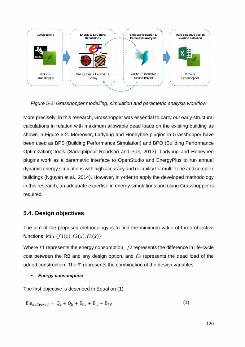
120
Figure 5-2: Grasshopper modelling, simulation and parametric analysis workflow
More precisely, in this research, Grasshopper was essential to carry out early structural
calculations in relation with maximum allowable dead loads on the existing building as
shown in Figure 5-2. Moreover, Ladybug and Honeybee plugins in Grasshopper have
been used as BPS (Building Performance Simulation) and BPO (Building Performance
Optimization) tools (Sadeghipour Roudsari and Pak, 2013). Ladybug and Honeybee
plugins work as a parametric interface to OpenStudio and EnergyPlus to run annual
dynamic energy simulations with high accuracy and reliability for multi-zone and complex
buildings (Nguyen et al., 2014). However, in order to apply the developed methodology
in this research, an adequate expertise in energy simulations and using Grasshopper is
required.
5.4. Design objectives
The aim of the proposed methodology is to find the minimum value of three objective
functions: Min {𝑓1(�̅�), 𝑓2(�̅�), 𝑓3(�̅�)}
Where 𝑓1 represents the energy consumption, 𝑓2 represents the difference in life-cycle
cost between the RB and any design option, and 𝑓3 represents the dead load of the
added construction. The 𝑥 ̅ represents the combination of the design variables.
Energy consumption
The first objective is described in Equation (1)
Ele𝑑𝑒𝑙𝑖𝑣𝑒𝑟𝑒𝑑 = Qc + Qh + Ehv + Ela − EPV (1)

Chapter 5: A methodology for multi-objective parametric analysis (MOPA)
121
Where Qc represents heating loads, Qh represents cooling loads, Ehv represents for the
auxiliary electricity of heating and cooling fans, Ela represents auxiliary electricity of
appliances and artificial lighting. The total energy consumption is substituted from the
electricity generation by the Photovoltaic (PV) represented by the EPV. Each of the
heating and cooling loads takes in account the Coefficient of Performance (COP), and
the primary energy conversion, which is the preferred metric according to the EPBD
directive. According to Equation (1), electricity has been identified as the main source of
energy. Other sources of energy for heating, such as gas, are not counted since the heat
pump is designed to be the main source of heating and cooling. Even though gas boilers
may be used in the existing building as the main source of heating, it has not to be
counted in this equation. The energy consumption is meant to be calculated for the
extension only, and not for the whole building.
Life Cycle Costing (LCC)
The second objective represents the difference of Life Cycle Costing (dLCC) of the
building between the design option 𝐿𝐶𝐶𝑖 and Life Cycle Costing of the Reference
Building 𝐿𝐶𝐶𝑅𝐵 as shown in Equation (2).
The reason behind choosing dLCC as a unit for evaluation returns back to the difficulty
of estimating an accurate global cost of the existing building or the existing building
components (e.g. existing floor or neighboring walls) that are attached to the roof
stacking unit. When calculating the dLCC, all expenses of the existing building
components are subtracted, and the variable building components are solely assessed.
Thus, Life Cycle Costing is represented by Equation (3), where IC represents the
investment cost of the building materials, RC represents the replacement cost of the
replicable items such as the windows and PV panels, MC represents the maintenance
cost, OC represents the operational cost in Belgium by the means of energy
consumption, and finally the C represents a constant value of the construction and
design cost. The symbol 𝑖 denotes the indexes for each design solution, while 𝑗 denotes
the index for each design parameter.
dLCC = 𝐿𝐶𝐶𝑖 − 𝐿𝐶𝐶𝑅𝐵 (2)
LCC = ∑ ICjij=1 + ∑ RCj
ij=1 + MC + OC + C (3)
122
The method in which the LCC has been based on the European Standards EN 15459 and ISO 15688-5 for the international standards for property life-cycle costing (EN 15459 - Energy performance of buildings - Economic evaluation procedure for energy systems in buildings, n.d.; ISO 15686-5:2008, n.d.). The calculations have been made over a 30 years life span as recommended by the EPBD, because assumptions on interest rates and energy prices are very uncertain beyond 30 years’ timeframe. Thus, each of the interest and discount factor with escalation rates, along 30 years, has been based according to the Belgian rates, which is equal to 0.078 and 15.43 respectively. Those values are considered in the replacement RC, and operational costs OC (Hamdy et al., 2013), represented by the following Equations (4) and (5).
𝑎𝑒 = 1 − (1 + 𝑟𝑒)−𝑛
𝑟𝑒⁄ (4)
𝑟𝑒 = 𝑟 − 𝑒1 + 𝑒⁄ (5)
Where 𝑎𝑒 is the discount factor taking in consideration the escalation rate of the energy
price and life space 𝑛, and 𝑟𝑒 represents the real interest rate 𝑟, which include the effect
of the escalation rate of energy prices.
In this research study, it is important to mention that the following conditions have been
considered when calculating the difference in Life Cycle Costing (dLCC):
To build on the rooftop of an existing building, in reality, their real costs include the
demolition of an existing roof, infrastructure (vertical water piper and electricity),
superstructure (walls, roof and windows), heating and sanitary system installation,
and finally interior finishing and carpentry. However, in this study, the cost of the
superstructure (walls, roof, and windows) has only been calculated in the LCC
calculations.
The LCC of the superstructure (Walls, Roof, and Windows) represents more than 40%
of the Global LCC of the whole building according to construction values in Brussels,
which remains of a great significance and interest compared to the Global Cost of the
whole building.
Each of the maintenance and constant costs (including labor cost) are excluded since
those factors are given the same value in the RB and each design option. On the
contrary, each of the initial, replacement, and operational costs are calculated and
makes a difference in the final value of the dLCC.

Chapter 5: A methodology for multi-objective parametric analysis (MOPA)
123
Dead Loads (weight of the added building materials)
The last objective is represented by Equation (6) which calculates the dead load of the
added construction. From a structural point of view, there are several factors that affect
the structural performance of a certain building, such as the dead load, live load, snow,
wind, and seismic loads. According to the variable load, the structure of the added floor
is designed. However, in this research, we are only concerned with the dead load of the
added floor, since each of the live loads, wind, snow and seismic loads would be given
the same values. Thus, the lighter the building is, the safer it is to be built on the rooftop
of an existing building, taking in consideration the limited capacity of the existing
foundation and soil to hold more constructional loads (Amer et al., 2017b). The dead
load is calculated by adding the constructional load of each component of the roof
stacking module and divide it by the total floor area.
DL = (∑ Wjij=1 + Rj + Fj + Gj + PVj) / 𝑚2 (6)
Where Wj represents the construction load of the wall, Rj is the construction load of the
roof, Fj is the construction load of the floor, Gj is the construction load of the windows,
PVj is the construction load of the added PV modules, and finally 𝑚2 is the total floor
area of the roof stacking module, which in this case entirely occupies the area of the roof
of the existing building.
In this research, constructional loads is meant to be calculated for the building envelope
only rather than the whole roof stacking module (including floors, side walls, interior
walls, and furniture). However, the reason behind not calculating the difference in the
added constructional loads, is due to the lack of precise estimates of the real specific
weight of existing construction. Therefore, the construction load is calculated in Kg/m2
rather than kN/m2. The loads of the added building envelope is calculated separately by
adding the weight of the building components without further unit conversions, which is
also simpler to understand for the different stakeholders in the decision-making process.

124
5.5. Discussion
In this chapter, the methodology and design objectives have been presented. In addition,
the tools that has been used / proposed for this methodology have been illustrated in a
systematic workflow. In fact, those tools are widely and increasingly used by
architectural and engineering offices. Therefore, the application of this methodology
could be widely used, and not limited to skillful researchers. However, minimum
expertise in using parametric simulation tools, such as Grasshopper and Honeybee
tools, is required to be able to apply this methodology. Thus, given the powerful tools
used in this research, this methodology is universally developed meaning that it is
possible to apply this methodology on bi-objective, as well as tri-objective design targets.
For instance, if the given existing building has enough capacity to hold additional stories
without a great concern on the added weight, then it is possible to exclude the
construction weight objective from the very beginning.
Finally, design objectives are not limited to cost, energy, or construction weight. Design
objectives could be expanded to include thermal comfort, daylighting or Life Cycle
Analysis (LCA), depends on the purpose of the study. However, in this research, the aim
is to focus on the dead loads limitations
Chapter 6: Application for cost-optimal zero-energy lightweight construction measures
125
6. Chapter Six: Application for cost-optimal
zero-energy lightweight construction
measures
This chapter, applies the developed methodology in the previous chapter. A case study
has been selected from Brussels, as a real reference building, representing the most
dominant housing typology.

126

Chapter 6: Application for cost-optimal zero-energy lightweight construction measures
127
6.1. Case Study
Since EPBD is concerned with the Member States of the European Union (EU)
(European Commission, 2018, 2010), Brussels Capital Region in Belgium, as the capital
of Europe, has been chosen for the location of the case study. Moreover, Brussels has
the fastest growing population among other Belgian cities, expecting 190,000 more
inhabitants by 2040 (Deboosere, 2010b; Paryski and Pankratieva, 2012b). Thus, urban
densification through roof stacking has been put forward as a prospect solution (Amer
et al., 2017b; Amer and Attia, 2018b). However, there is a lack of any benchmark or a
reference that represents the performance of roof stacking buildings in Brussels.
Therefore, a Reference Building (RB) has been developed in this research. There are
three different models to identify a RB: Real, example, and theoretical (Brandão de
Vasconcelos et al., 2015; Corgnati et al., 2013): Real RB simply represents an existing
building for a certain typology, where the characteristics of the building are identified,
and performance is measured based on monitored data. Example RB represents an
ideal building defined based on the inquiries and assumptions of experts, whereas,
theoretical RB is identified based on statistical data.
Development of the real reference building
In Brussels, there are several building typologies that differ in layouts and composition.
In order to narrow down the selection, building typologies have been identified based on
the review of the literature. Firstly, there is a distinct difference between residential
buildings that were built before 1945 and after, which marks the end of the Second World
War and the beginning of a new era of industrialization in the field of construction. The
majority of the existing buildings are those that were built before 1945, representing 71%
of the existing residential building in Brussels, which had similar characteristics in terms
of building’s scale, height, and typologies (Van de Voorde et al., 2015b). Among those
buildings, middle-class housing typology represents the most prevailing typology, which
represents 78% of the total residential buildings that were built before 1945. In this
research, a real RB has been selected as shown in Figure 6-1, based on the previous
statistics given the most representative housing typology in Brussels (Van de Voorde et
al., 2015b). Building parameters and variables have been precisely identified according
to the available building materials and components in the Belgian market in order to
represent a real project’s condition.

128
Figure 6-1: Selected case study in Brussels following the typology of middle-class housing
Roof stacking model characteristics
The RB has been developed and identified under two main sets: (a) Geometry and
Function according to the Belgian housing typology, and (b) envelope and system.
Roof Stacking geometry and function
The geometry of the roof stacking floor is composed of two bedrooms zones and a zone
for stairs and bathroom as shown in Figure 6-2. The building is similar to a row house
with two side walls next to two neighboring buildings, facing the north-south direction as
shown in Figure 6-3. The added floor follows the same layout of the floor below with a
shorter length of 9 meters length and 6 meters in width. The first and second zones have
areas of 22 m2 and 14 m2, while the last zone has an area of 8 m2, to make the whole
floor with an area of 44 m2. However, the Treated Floor Area (TFA), is calculated for the
two bedrooms that makes an area of 36 m2.

Chapter 6: Application for cost-optimal zero-energy lightweight construction measures
129
Figure 6-2: architectural plan for the case study. On the left is the layout before intervention. On the right is the roof stacking plan composed of 2 rooms, stair hall
and bathroom
Figure 6-3: The elevation of the caqse study before and after roof stacking

130
Roof Stacking envelope and system
As shown previously, building geometry has been designed based on the existing layout
of the housing typology, whilst the characteristics and composition of the building
envelope have been designed based on lightweight materials and higher performance
standards. The thermal characteristics of the building materials, namely the thermal
conductivity, specific heat capacity, and density, have been defined based on the
standard EN ISO 10456 (EN ISO 10456, n.d.). The cost of the building materials, which
is used to define the Life Cycle Cost (LCC) of the RB, has been defined based on the
database of the Belgian construction works for 2017 entitled “Bordereau des Prix
Unitaires”.
The characteristics of the Roof Stacking’s building envelope have been identified based
on the real onsite construction measures. The walls facing the north and south directions
are made of lightweight timber frames and 160 mm mineral wool insulation, with a U-
value of 0.19 W/m2.K. The roof section is made as well of lightweight timer frames but
with 160 mm mineral wool insulation to have a U-value of 0.18 W/m2.K. The north façade
that occupies the Bedroom has a Window to Wall Ratio (WWR) of 20%, while the south
façade, which occupies the Living room has a WWR of 30%. Both windows are made of
double-glazing, with a U-value of 1.1 W/m2.K, g-value 60% and a frame U-value of 1.57
W/m2.K, with an average effective window U-value of 1.2 W/m2.K. The windows are
designed to prevent thermal bridges, given that the quality of construction is high. The
U-values of the side walls and floor are equal to 0.25W/m2.K and 0.35W/m2.K
respectively. However, the precise composition of both elements has not been taken
into consideration since they are designed in bricks. Instead, wall and floor sections with
equivalent thermal transmittance values (U-values) have been substituted to maintain
an overall lightweight construction. Detailed layers of construction for the Wall and Roof
sections of the Roof Stacking module is presented in Table 6-1.

Chapter 6: Application for cost-optimal zero-energy lightweight construction measures
131
Table 6-1: Reference building’s envelope design of roof stacking Reference Building (RB)
Reference wall section of roof stacking Initial Cost
(Euros/m2)
Dead Load
(Kg/m2)
Total wall
area
Larch (Cladding) 25.00 14.4
74.55
Gypsum (Plaster Board) 45.00 11.5
OSB (Particle Board) 30.00 6.2
Mineral Wool 16 cm (Insulation) 35.00 12.8
OSB 30.00 6.2
Gypsum 45.00 11.5
Timber Frame (38/230mm) 55.00 20
SUM 265.00 82.6
Reference roof section of roof stacking Initial Cost
(Euros/m2)
Dead Load
(Kg/m2)
Total roof
area
Sealing (Bitumen) 75.00 20
44
OSB (Particle Board) 30.00 6.2
Mineral Wool 16 cm (Insulation) 35.00 16
OSB 30.00 6.2
Gypsum 45.00 11.5
Timber Frame (38/230mm) 55.00 20
SUM (Real) 270.00 79.9
Given the scope of this research, which focuses on the building envelope construction,
the HVAC system has not been designed according to the onsite measures. Instead, a
hypothetical Heat Pump has been assigned for the developed Roof Stacking RB, which
is responsible for heating and cooling, with a Coefficient of Performance (COP) of 4. To
achieve indoor thermal comfort, set point temperatures for heating and cooling have
been identified based on ASHRAE standard 55-2004 for adaptive comfort model and
the recommended indoor temperatures as defined in the reference passive house, with
a 20C for heating set point and 26C for cooling set point. In this model, indoor air
temperatures should not exceed the 25C for 5% of the occupied hours to comply with

132
the Belgian passive house standards. As for the ventilation, a mechanical system with
heat recovery has been added, namely system D. The efficiency of the heat recovery
system is designed at 80%, with a constant air flow of 30 m3/h for each room. Regarding
the consumption of the Domestic Hot Water (DHW), it has not been considered in the
calculations. Given the nature of roof stacking buildings, DHW is assumed to be
previously provided in the existing building. Moreover, according to previous studies
(Hamdy et al., 2013), it was found that solar heaters have lower economic availability
compared to PV system. Solar heaters were found to increase the investment cost and
the replacement cost since it has shorter life-space than the PV system. Whereas the
electricity consumed by house appliances and lighting has been designed with a
constant value of 19.8 kWh/m2, which means that lighting consumption has not been
designed based on the indoor daylighting availability.
Simulation and calibration
As shown in the previous section, the parameters of the RB have been set based on two
different sets of information: (a) Geometry and function, (b) Envelope and system.
Several adjustments have been made from each set to match the specific characteristics
of a roof stacking building. The RB has been simulated and calibrated based on the
monitored values of the reference building as a way to reduce the gap between the real
measurements and the simulated ones (De Wilde, 2014). The calibration has been made
based on the monthly monitored values of the heating demand and average indoor
temperature.
In order to calibrate the RB simulation model, the settings of the defined model
characteristics have been set as constants, while variations on the occupancy schedules
and the U-value of the neighboring side walls have been applied. The variation of the
occupancy schedule has been set within a margin of ± 4 hours. While, U-value of the
neighboring side walls are set to vary between 0.2 and 0.8 W/m2K, with a 0.05 W/m2K
uniform step. A total of 1,024 options could be achieved when cross-referencing the
operational, occupancy schedule parameters and neighboring side walls. Thus, Genetic
Algorithms (GA) has been used to run an automated calibration, which brings optimized
fitness values after 270 simulations runs only. The tools that have been used for
calibration are the same used in the parametric simulation and data analysis. More
information and details are explained in the next sections.

Chapter 6: Application for cost-optimal zero-energy lightweight construction measures
133
Two indices have been used to verify the good-to-fit of the building energy and thermal
model (Ascione et al., 2016a; Cacabelos et al., 2017; Royapoor and Roskilly, 2015). The
first index is the Mean Bias Error (MBE) as shown in the first equation, and the
Coefficient of Variation of the Root Mean Square Error (CV (RMSE)) as shown in the
second equation.
MBE = ∑ (𝑚𝑖 − 𝑠𝑖)𝑁𝑝𝑖=1 / ∑ 𝑚𝑖
𝑁𝑝𝑖=1 [%] (6.1)
CV (RMSE) =√∑ (𝑚𝑖 − 𝑠𝑖)2 𝑁𝑝𝑖=1
𝑁𝑝⁄ [%] (6.2)
Where the 𝒎𝒊: (i = 1, 2, 3 …, Np) represents the monitored data points (i.e. energy
consumption), while 𝒔𝒊: (i = 1, 2 … Np) represents the simulated data points. Mean Bias
Error (MBE) represents a non-dimensional measure of the bias error between the
simulated and measured data in a certain time resolution. RMSD represents the
standard deviation of the differences between the simulated and measured data, which
aggregates the magnitudes of the errors for various times into a single measure. Both
indices are expressed in percentages. Based on the guidelines of ASHRAE 14-2002 and
2014, the maximum threshold for MBE is 5% for monthly calibrated data points and 10%
for hourly calibrated data points. CV (RMSE) requires a maximum threshold of 15% for
monthly calibrated data points and 30% for hourly calibrated data points. Figure 6-4
represents the calibration results of the monthly heating demand, where the values of
MBE and CV (RMSE) are equal to 2.1% and 7.3% respectively. While the values of the
monthly average indoor temperature are equal to 1.3% and 4.7% respectively. The
calibration values for both the heating demand and indoor temperatures ensure the
reliability of the simulation model to be used in further analysis.
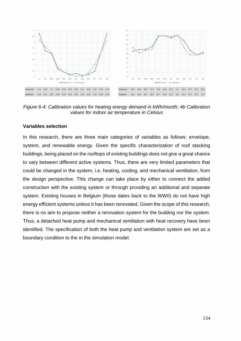
134
Figure 6-4: Calibration values for heating energy demand in kWh/month; 4b Calibration values for indoor air temperature in Celsius
Variables selection
In this research, there are three main categories of variables as follows: envelope,
system, and renewable energy. Given the specific characterization of roof stacking
buildings, being placed on the rooftops of existing buildings does not give a great chance
to vary between different active systems. Thus, there are very limited parameters that
could be changed in the system, i.e. heating, cooling, and mechanical ventilation, from
the design perspective. This change can take place by either to connect the added
construction with the existing system or through providing an additional and separate
system. Existing houses in Belgium (those dates back to the WWII) do not have high
energy efficient systems unless it has been renovated. Given the scope of this research,
there is no aim to propose neither a renovation system for the building nor the system.
Thus, a detached heat pump and mechanical ventilation with heat recovery have been
identified. The specification of both the heat pump and ventilation system are set as a
boundary condition to the in the simulation model.

Chapter 6: Application for cost-optimal zero-energy lightweight construction measures
135
Figure 6-5: Illustration of the reference roof stacking, showing design variables in blue, and boundary conditions in black
Building’s envelope of the new construction is prone to a wide variety of building
materials, including walls, roof, windows, and their specifications. The same goes for
adding renewable energy source when it comes to the number of photovoltaic (PV)
panels, area, tilt angle, and orientation. It is important to highlight that the application of
the developed methodology is not limited to the selected variations. Instead, it is possible
to include all categories in the simulation whenever it is application and concerned with
the decision-making process.
Design Variables of the building envelope are concerned with three main sections of the
superstructure of the building: wall section, roof section, and windows.. In this research,
only the insulation for each section is considered as the main variable, in terms of type
and thickness. The other layers are kept the same, so as not to change their minimum
thermal performance and to comply with passive house standards. The reason behind
choosing passive house standard to assign the design variables returns back to the
policy measure requirement to follow passive standard to newly built residential
buildings. Given the critics on the application of passive house standards from the LCA

136
and LCC perspectives (Allacker and De Troyer, 2013), this research is concerned with
following passive standards while considering the cost factor.
As shown in Table 6-2, four different types of insulations are examined: Expanded
Polystyrene Foam EPS, Cellulose, Mineral Wool (MW), and Wood Fiber (WF). The
choice of the insulation materials returns back to the common practices in the Belgian
construction market. The thermal specifications of insulation materials, in terms of
thermal conductivity, heat capacity and density, have been identified based on the
standard EN ISO 10456 (EN ISO 10456, n.d.). The load of the added construction is
calculated based on the specific weight of the building materials composing the envelope
section. Whilst the average prices of the building materials have been identified based
on the database of the Belgian construction works for 2017 entitled “Bordereau des Prix
Unitaires”. The minimum thicknesses of the insulation materials for both the wall and
roof sections have been identified to comply with the passive house standard, which
requires a minimum U-value of 0.15 W/m2K for the wall section and 0.10 W/m2K for the
roof section. Therefore, a minimum thickness of 240 mm has been assigned for both the
wall and roof insulations. For both the wall and roof section, a uniform step of 4cm has
been given as the parametric variation with a maximum 5 steps for the wall section and
7 steps for the roof section.
Windows parameters vary under two categories: glazing type and ratio. In the first
category, two different glazing types have been examined; the first is triple glazing with
argon filling with a thickness of 36 mm and U-value of 0.75 W/m2K, while the second is
also triple glazing with argon filling but with a thickness of 44 mm and U-value of 0.6
W/m2K. In the second category, WWR changes from 20%, as the minimum ratio that
secures adequate daylighting for the indoor spaces, up to 90%. Both variations are
applied to the northern and southern facades for both rooms.

Chapter 6: Application for cost-optimal zero-energy lightweight construction measures
137
Table 6-2: Types of insulation materials for roof stacking
Wall Insulation
(Max. 0.15 W/m2K)
U-values
(W/m2.K)
Specific weight
(kg/m3)
Investment cost
(Euros/m3)
EPS 0.15 - 0.085 30 300.00
Cellulose 0.15 - 0.092 45 92.00
Mineral Wool 0.15 - 0.082 20 216.00
Wood Fiber 0.15 - 0.097 35 318.00
Roof Insulation
(Max. 0.10 W/m2K)
U-values
(W/m2.K)
Specific weight
(kg/m3)
Investment cost
(Euros/m3)
EPS 0.10 - 0.077 30 300.00
Cellulose 0.10 - 0.084 45 92.00
Mineral Wool 0.10 - 0.075 20 216.00
Wood Fiber 0.10 - 0.088 35 318.00
Window Type
(Max. 0.75 W/m2K)
U-values
(W/m2.K)
Specific weight
(kg/m2)
Investment cost
(Euros/m2)
Triple glazing (36
mm) with Ar. filling 0.75
30
650.00
Triple glazing (44
mm) with Ar. filling 0.60 750.00
PV Type Efficiency (%) Specific weight
(kg/m2) Investment cost
(Euros/m2)
PV 1 15 15
500
PV 2 20 700
138
In this research, the minimum requirements of each of the fire resistance class REI and
the weighted sound reduction index Rw [dB], have been taken in consideration and
calculated based on EN 13501-2 (EN 13501-2, n.d.), and EN ISO 140-1 and EN ISO
717-1 (EN ISO 140-1, n.d.; EN ISO 717-1, n.d.), respectively. According to the Belgian
standards, the required fire resistance of building elements is relative to the height of the
building as shown in Chapter 1, which is classified into a low, medium and high rise. In
this research, it is assumed that the added floor on would raise or remain the existing
building under the medium height building, which ranges between 10 and 25 meters
height.
6.2. Multi-Objective Parametric Analysis (MOPA)
The proposed Multi-Objective Parametric Analysis (MOPA) for the assessment of the
cost-optimal, zero-energy and lightweight construction has been applied to the
developed roof stacking RB, in which optimal design solutions that follow the Belgian
passive house standards are identified. MOPA has been carried out on three stages.
The first stage conducts a parametric analysis on the superstructure’s building
components separately (walls, roof, and windows). For running a parametric simulation
on one group (e.g. wall), the other groups (e.g. roof and windows) is set on their default
parameters (i.e. passive house setting). The second stage conducts a parametric
analysis on the optimum design variables resulted from the first stage. The third and last
stage conducts a parametric analysis on renewable energy resource in combination with
the optimum design variables of the whole building’s envelope resulting from the second
stage.
In order to speed up the simulation process, the time step setting has been reduced from
2, as the default value, to 1. In principle, the simulation runs on an hourly basis. However,
each hour is divided into smaller steps to result in the average performance (e.g.
temperature or energy consumption) of a single hour. Reducing the simulated steps in
one hour gives relatively less precise results. However, this research focuses on
comparing different results with each other rather than giving a precise value of building’s
performance. Thus, once optimal results are identified, it is recommended to rerun
simulations with higher precision settings. The RB has been modeled and simulated
using EnergyPlus via Ladybug and Honeybee plugins in Grasshopper. The values of

Chapter 6: Application for cost-optimal zero-energy lightweight construction measures
139
annual energy consumption as results of heating, cooling, and auxiliary electricity
demands are assessed for direct electricity usage. Each simulation run takes between
8 - 10 seconds by using the “conduction transfer function” algorithm with 1 time-step per
hour.
Parametric analysis for individual groups
For each of the wall and roof sections, insulation type and thicknesses have been set as
parametric variables for simulation. There are a total of 20 simulation runs for the wall
section, and 28 simulation runs for the roof section as shown in Figures 4 and 5
respectively. A bi-objective parametric analysis has been carried out to examine the
influence of insulation on energy consumption and the dLCC. The effect of the
parametric variations has not been examined on the third design objective due to its
negligible effect on the overall construction load.
Figure 6-6: MOPA on design variables of wall section
Figure 6-7: MOPA on design variables of roof section
The parametric analysis has been carried out on the basis of cross-referencing all design
variables together; giving all possible options of design variables combinations. The
outcomes are plotted on a 2D graph, where Pareto Front is identified mathematically in
red color. Out of 20 options of design variables for the wall section, we get 7 optimum
results and 8 optimum results out of 28 options of design variables for the roof section
represented by the red points. Pareto front represents the results that achieve minimum
values for the given objectives Min {𝑓1(�̅�), 𝑓2(�̅�)}
-80
-60
-40
-20
0
20
40
60
33 33.5 34 34.5 35 35.5 36
dL
CC
(E
uro
s/m
2)
Energy Consumption (kWh/m2.yr)
Population Pareto Front
-80
-60
-40
-20
0
20
40
60
33 33.5 34 34.5 35 35.5 36
dL
CC
(E
uro
s/m
2)
Energy Consumption (kWh/m2.yr)
Population Pareto Front
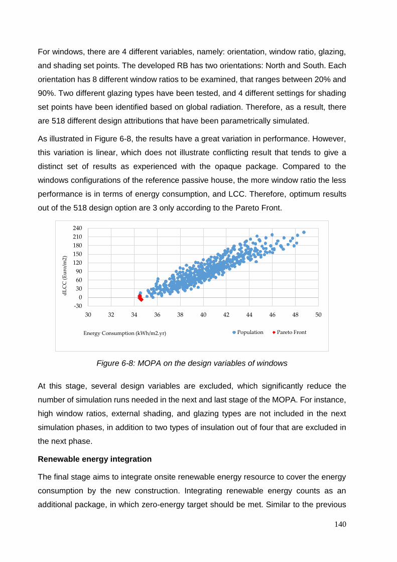
140
For windows, there are 4 different variables, namely: orientation, window ratio, glazing,
and shading set points. The developed RB has two orientations: North and South. Each
orientation has 8 different window ratios to be examined, that ranges between 20% and
90%. Two different glazing types have been tested, and 4 different settings for shading
set points have been identified based on global radiation. Therefore, as a result, there
are 518 different design attributions that have been parametrically simulated.
As illustrated in Figure 6-8, the results have a great variation in performance. However,
this variation is linear, which does not illustrate conflicting result that tends to give a
distinct set of results as experienced with the opaque package. Compared to the
windows configurations of the reference passive house, the more window ratio the less
performance is in terms of energy consumption, and LCC. Therefore, optimum results
out of the 518 design option are 3 only according to the Pareto Front.
Figure 6-8: MOPA on the design variables of windows
At this stage, several design variables are excluded, which significantly reduce the
number of simulation runs needed in the next and last stage of the MOPA. For instance,
high window ratios, external shading, and glazing types are not included in the next
simulation phases, in addition to two types of insulation out of four that are excluded in
the next phase.
Renewable energy integration
The final stage aims to integrate onsite renewable energy resource to cover the energy
consumption by the new construction. Integrating renewable energy counts as an
additional package, in which zero-energy target should be met. Similar to the previous
-30
0
30
60
90
120
150
180
210
240
30 32 34 36 38 40 42 44 46 48 50
dL
CC
(E
uro
/m2)
Energy Consumption (kWh/m2.yr) Population Pareto Front
Chapter 6: Application for cost-optimal zero-energy lightweight construction measures
141
step in finding optimal variables for the building envelope, the specifications of the PV is
based on their availability in the Belgian market. Accordingly, one type of PV has been
selected to be examined in this research work made of polycrystalline silicon modules,
with a robust aluminum frame to withstand wind and snow loads up to 5400Pa. One PV
panel has the dimensions of roughly 1.5m length x 1m width, which makes it of 1.5 m2
area with an efficiency of 16.69%, and cost 900 Euros per panel.
In terms of design variations of PV panel, each of the orientation, tilt angle, and the
number of panels are counted, not to mention PV specifications, which has been
identified as constant in this study. Yet, not all PV design variations have been taken
into consideration in this research. Given the layout configuration of the case study, it is
easy to determine the most efficient orientation and tilt angle based on the weather file
of Brussels city. Thus, PV panels have been set up towards the south direction with 40
degrees tilt angle. Accordingly, only the number of PV panels has been up as a design
variable when integrating renewable energy resource.
By changing the maximum number of PV panels, the total area ranges between 1.5
(equivalent to one PV panel) and 22.5 m2 (equivalent to 15 PV panels) for the RB in this
study. However, the more panels, the more cost, and loads added to the building.
Therefore, the last stage aims to conduct MOPA on all design objectives, which means
that cost-optimal zero-energy results are targeted while seeking the least amount of PV
panels on the rooftop to reduce the overall constructional load on the rooftop.
Total energy consumption has been calculated after considering the amount of energy
produced by the PV panels. Therefore, the value of the final energy consumption varies
between positive (+) and negative (-). Positive values indicate that the building does not
meet zero energy targets. While negative values represent zero-energy or positive
energy buildings, which produces more energy than consumed. Evaluation and
selection.
Cost-optimal zero-energy lightweight construction selection
In this step, the results are illustrated in a 3D graph representing the three axes
objectives: X-axis for energy consumption [kWh/m2/yr.], Y-axis for dLCC [Euros/m2],
and Z-axis for the load of construction [Kg/m2]. Moreover, the results are divided into
four quadrants, as previously explained in the methodology section. However, in this
case study, the four quadrants are illustrated based on the thresholds of the main design

142
objectives: Energy consumption and dLCC. The thresholds are marked at the “Zero
Points”, where negative values represent either a cost-efficient or zero-energy building,
or both. As shown in Figure 6-9, the first quadrant refers to the solution space that lies
in the cost-optimal zero-energy design solutions. The three rest quadrants may
represent optimal solutions but for single design objectives.
Figure 6-9: Plotting results on a 3D graph. Solution space are divided into four quadrants, where cost-optimal zero-energy lightweight construction are located in the
inner quadrant as marked on the Figure
In terms of the overall construction load, we found that all design options were heavier
than the RB. This is due to the fact that the higher building’s performance the more
materials are added to the buildings, such as insulation boards, and the more PV panels
are required, which contributes to the overall construction load. However, in the 3D
graph, we aim to identify cost-optimal zero-energy design options with the least
construction load, which leads to the next step of selecting optimum design variables.

Chapter 6: Application for cost-optimal zero-energy lightweight construction measures
143
Optimum variables selection
All design variables represented in the 3D graph are plotted in a parallel coordinated
graph as shown in Figure 6-10 and 6-11. The columns on the left side represent the
range of design variables, while the right columns represent the objectives.
Figure 6-10: Parallel coordinated graph for all design options
Figure 6-11: Parallel coordinated graph for selected design options
Table 6-3 gives all design options while highlighting the cost-optimal design variables
and their equivalent design objective results for each of the energy, cost, and load of
construction, which are marked in gray.
Throughout the parallel coordinated graph, it is possible to select optimal design
variables based on the following settings:
In order to select the cost-optimal zero-energy design options, all design
objectives should have negative values, which start from 0 to -30 kWh/m2/yr. for
energy consumption and from 0 to -200 Euros for the dLCC, as shown in Figure
6-11.
Out of the selected design options, there is a variety of construction loads, which
represents the solution space of cost-optimal zero-energy and lightweight
construction.

144
From the design variables columns, it is possible to identify additional boundaries.
For instance, it is possible to choose one type of insulation, certain thickness, or
the number of PV panels, which lie in within the optimal solution space.
Table 6-3: Cost-optimal zero-energy design options
VARIABLES OBJECTIVES
Wall Roof Insulatio
n
PV
Length
PV
Width kWh/m2/yr.
dLCC /
m2 Kg / m2
0.36 0.32 Cellulose 5 3 -29.30 -201.98 203.06
0.32 0.36 Cellulose 5 3 -28.75 -203.62 201.11
0.4 0.32 Cellulose 5 3 -28.21 -206.57 198.71
0.36 0.32 Cellulose 5 3 -27.75 -206.63 197.51
0.32 0.32 MW 5 3 -29.94 -117.82 211.17
0.4 0.28 Cellulose 5 3 -29.51 -200.01 204.26
0.36 0.28 Cellulose 5 3 -29.01 -201.98 202.31
0.32 0.28 Cellulose 5 3 -28.52 -204.02 200.35
0.28 0.28 Cellulose 5 3 -28.26 -205.63 199.15
0.4 0.24 MW 5 3 -27.91 -206.49 197.95
0.36 0.24 Cellulose 5 3 -27.47 -205.32 196.75
0.32 0.24 Cellulose 4 3 -15.38 -159.14 194.47
0.32 0.24 Cellulose 4 3 -15.71 -158.15 195.22
0.28 0.24 Cellulose 4 2 0.76 -94.71 191.67
0.28 0.24 Cellulose 3 3 -3.15 -110.43 192.18
0.28 0.24 Cellulose 5 2 -7.06 -126.15 192.69
0.28 0.24 Cellulose 4 3 -14.90 -157.60 193.71
0.28 0.24 Cellulose 2 3 8.12 -64.79 191.40
0.28 0.24 MW 5 2 -7.54 -127.69 193.44
0.28 0.24 Cellulose 5 3 -27.60 -206.33 197.20
0.24 0.24 Cellulose 1 1 28.20 15.36 188.09
0.24 0.24 Cellulose 2 1 24.28 -0.36 188.60
0.24 0.24 Cellulose 1 2 24.28 -0.36 188.60
0.24 0.24 Cellulose 3 1 20.36 -16.08 189.11

Chapter 6: Application for cost-optimal zero-energy lightweight construction measures
145
0.24 0.24 MW 1 3 20.36 -16.08 189.11
0.24 0.24 MW 4 1 16.44 -31.81 189.62
0.24 0.24 MW 2 2 16.44 -31.81 189.62
0.24 0.24 Cellulose 5 1 12.52 -47.53 190.13
0.24 0.24 Cellulose 3 2 8.60 -63.26 190.65
0.24 0.24 Cellulose 2 3 8.60 -63.26 190.65
0.24 0.24 Cellulose 3 2 8.12 -64.79 191.40
0.24 0.24 Cellulose 2 3 8.12 -64.79 191.40
0.24 0.24 Cellulose 5 3 -27.14 -206.31 196.00
Cost optimal and zero-energy Non-cost-optimal or zero-energy
6.3. Discussion
This research work introduces a new methodology that aims to achieve cost-optimal
zero-energy lightweight construction. This research contributes to the field of multi-
objective optimization. However, the developed methodology in this research utilizes no
optimization algorithms. Instead, a novel method has been developed, denoted as
MOPA, “Multi-Objective Parametric Analysis”. As comprehended from the denotation,
the methodology heavily relies on parametric analysis, by the means of simulation, in
order to find optimum results for multiple design objectives. This methodology reduces
the time and effort required to achieve multi-objective optimal results, compared to
optimization algorithms. We were able to surpass the complexity of using and
understanding optimization algorithms, not to mention the paradox of choosing the right
algorithm for the right design objective (Waibel et al., 2019; Wortmann et al., 2017).
Even though roof stacking buildings have been witnessed widely in Brussels and
Europe, we found no reference building developed for such type of construction. Thus,
in this research, a real reference building for roof stacking housing has been developed.
The economic feasibility objective has been studied by the means of LCC on a 30 years’
time-span, where the design objective referred to the difference in the LCC between the
RB and the design option, denoted as dLCC. However, it is important to highlight that
this research is not meant to calculate the Global Cost (GC) of the whole building.
Instead, the LCC calculations are subjected to specified building elements namely

146
superstructure (Walls, Roof, and Windows). The initial cost of superstructure’s element
represents 42% of the Global Cost of the roof stacking building, which includes
demolition, infrastructure (vertical water piper and electricity) and superstructure
elements, heating, and sanitary system, interior finishing and carpentry. Moreover, when
calculating dLCC, each of the maintenance and labor costs has been excluded, since
they have the same value for each of the RB and a given design option.
The same method of calculating the LCC goes for the calculation of construction weight.
The weight of superstructure elements has been calculated instead of the weight of the
whole roof stacking. However, we have not performed a difference in construction weight
between the RB and a design option for a couple of reasons. First, we had no precise
numbers for the actual not theoretical construction weight of the RB. Second, total
variable loads (including live, wind, snow, and seismic loads) would have to be
considered if the whole weight of the construction is calculated. Instead, when counting
for specific building components, it would be simple enough to count the weight of each
building component, which partially represents the dead load of the new construction.
In the simulation process using MOPA, and in order to speed up the simulation process,
the hourly step has been reduced from 6 to 2 in the simulation settings. Hourly steps
identify the number of simulation runs in one single hour, which contributes to the
precision of the simulation results. However, when conducting a comparative analysis
(i.e. similar to MOPA), precision in the simulation results are not highly considered.
Finally, Design variations in the HVAC system have not to be studied in this research.
The exclusion of the HVAC system in the design variables returns back to the boundary
conditions of the project. However, it is recommended to include HVAC system when
considering the whole building in the analysis process.
Also, we conducted a comparative analysis between the newly developed MOPA, and
optimization algorithms that are commonly used in building performance simulations.
Four different optimization algorithms have been used in the study: HypE, SPEA2,
RBFMOpt and NSGA-II. Each of HypE and SPEA2 are conducted using Octopus plugin,
while RBFMOpt and NSGA-II multi-objective optimization algorithms are conducted
using Opossum plugin (Optimization Solver with Surrogate Models) in Grasshopper.
This comparative analysis aims to assess the performance of different optimization
algorithms to solve a tri-objective design problem and to identify the qualities between
using optimization algorithms and parametric analysis.

Chapter 6: Application for cost-optimal zero-energy lightweight construction measures
147
Figure 6-12 shows the results of the comparative analysis, where X-axis represents the
number of simulation runs concerning Y-axis, which represents the median
Hypervolume, based on five runs for the optimization algorithm. The algorithms are
tested through five runs, which is different from the MOPA. Optimization algorithms are
non-deterministic, whereas MOPA is deterministic. This means that MOPA gives the
same results every time. The Hypervolume is normalized between 0, being the worst
performance, and 1 being the best performance.
Figure 6-12: comparison of the Hypervolume of MOPA against the four optimization
algorithms

148

Chapter 7: Conclusion
149
7. Chapter Seven: Conclusion
In this chapter, the research hypothesis are revisited and the findings, strength and
limitation are discussed, with an eye towards future work.

150
Chapter 7: Conclusion
151
7.1. Summary of the main findings
Urban densification:
Brussels Capital Region has been taken as a case study. Through the application and
the validation of a developed methodology that determines the potential of urban
densification through roof stacking, the following findings have been concluded:
- Brussels city can accommodate more than 59,000 additional inhabitants, which
represents approximately 30% of the expected increase in population by 2040,
by applying only roof stacking and increasing the height of existing buildings,
while still respecting the actual urban regulations and the building strengths.
- In addition, a theoretical potential was proposed to accommodate more than the
expected population increase by the same year, provided that the urban planning
regulations are relaxed with regard to the height of buildings in the less dense
area.
- In total, there are 887.6 hectares in the Brussels Capital Region that are
constructible and therefore available for densification. However, these areas are
currently empty. Out of the total area, 185.6 hectares of net land value is directed
toward infill building land for housing and 702 hectares is allocated for large urban
projects (COOPARCH-RU 2013). These areas of large urban projects can be
used to build residential buildings and urban services and to establish new areas
of economic activity and facilities, such as schools, hospitals, sports facilities, and
cultural facilities.
- If we consider that 185.6 hectares, which is equivalent to 1.856 km2, could be
used for infill development, an estimated 20% of this amount can be allocated to
building uninhabitable areas such as walls, which leaves only 80% of the total
area, equivalent to 1.48 km2, for net residential functions. When this number is
multiplied by 4, for an estimated 4 floors per building, it gives us a total of 5.93
km2 of inhabitable area. Compared to the given potential by roof stacking, which
is equivalent to 2.256 km2 in the first scenario, we find that infill development has
a potential for accommodating population that is more than two times higher that
of the lowest estimate of roof stacking.

152
It is important to mention that these values count only the estimated urban and structural
potential of adding additional buildings or floors, without considering the social
acceptance for each specific building plot, which will reduce these theoretical potentials.
Yet, the key strength of this the proposed methodology is its ability to create maps and
aid in decision making with the least amount of information.
Multidisciplinary approach:
Based on a robust classification of roof stacking construction methods, investigating over
136 roof stacking projects around Europe, and a wide survey among building engineers
and ranking analysis on the aspects that affects the decision making process on roof
stacking, the following outcomes have been concluded:
- Whereas six main attributes were identified to affect the decision-making on
assembly methods, designated as safety, accessibility, cost, time, environmental
impact, and quality of construction, which present a unique opportunity to
expedite the improvement of the roof stacking construction process.
- Logistics factor includes, but not limited to, the considerations related to loading
and transport the roof stacking modules, the space for trucks and auxiliary
equipment next of the building work, provision of the large-tonnage crane,
collection, in addition to loading and transfer of the demolition waste.
- The technical aspects, as well as the economic viability of those technical aspects
(e.g. added structure, purchasing construction license, or the need to first apply
improvements on the existing building), plays an important role in the decision-
making of the most appropriate load bearing methods.
If the targeted respondents is changed, such as contractors or clients, the final results
would definitely change. Factors related to the safety of workers is common in the
outcome of this research and previous research. Even though the responsibility of
workers health and safety lies within the contractor’s responsibility, it represents a high
concern for all parties. From another perspective, the results reveal important indicators.
The overseen direct relation between the thermal mass of building materials and the
overall energy consumption is not evident. This issue reveals practitioners’ point of view
on building physics and its direct relation to the overall thermal and energetic

Chapter 7: Conclusion
153
performance of the building. In other words, reducing energy consumption may be seen
to be approached by adding more insulation or photovoltaic panels. Similar point to be
mentioned is the relation between post-occupancy cost and energy consumption. The
tendency to consider energy consumption seemed to be a certain quality that
practitioners aim to achieve. This aim was not directly related to the cost, given that
achieving energy efficient building requires higher initial cost, as much as being a
targeted value.
Zero-energy cost-optimal lightweight roof stacking
The methodology developed in this research provides a new approach to achieve multi-
objective design targets without employing optimization algorithms. We avoid the
complexity and paradox of choosing the right algorithm, which is hard to determine for
many building engineers. Accordingly, this methodology facilitates and provides an
informed decision-making process to achieve multi-objective design targets. When
applying MOPA on the roof stacking RB, we found the following:
Using cellulose for insulation in the wall and roof sections was found to provide the
most efficient results in terms of financial viability. The second recommended
insulation material would go for Mineral Wool with a minimum 40 cm thickness of
insulation for each of the wall and roof sections. Mineral Wool is recommended for
higher energy efficiency measures, though associated with higher cost.
The relation between WWR and each of energy and financial efficiency is directly
proportional, which is illustrated by the linear relationship between energy
consumption and dLCC. In terms of energy consumption, it was found that the bigger
the area of the window, the more heat losses is accompanied. Also, the cost of one
square meter of the wall section of a RB is € 295, which is equivalent to 45% of the
rough cost of one square meter of the window, which is € 650.
On the contrary, the relationship between WWR and weight of the construction is
inversely proportional. The more window ratio is the less construction weight. This is
due to the weight difference between one square meter of glazing that is equal to 30
Kg, which is equivalent to 36% of the rough weight of one square meter of a wall
section, for example, that is equal to 82.6 Kg. Although minimal window ratios are
recommended for cost-optimal and energy-efficient measures, it is important to
154
ensure that windows provide the minimum requirement for daylighting to the indoor
spaces
Lastly, this study developed the first of its kind, a theoretical passive RB for roof
stacking in Brussels. By introducing this RB, we align with EBPD recast comparative
framework methodology. Moreover, it is possible to provide general
recommendations for cost-optimal zero-energy and lightweight construction for roof
stacking buildings in Brussels. However, there are several limitations in this study that
return back to the boundary conditions of the case study. The LCC of the Global Cost
(GC) has not been calculated in this research, Instead, the LCC of the superstructure
building elements (walls, roof, and windows) are only considered in the LCC
calculations. We found that other variations that contribute to the GC, such as
demolitions, infrastructure, and interior finishing do not contribute to the optimization
process in the developed methodology.
7.2. Innovations and limitations of the thesis
This research proposes several interventions and innovations in the field of urban
densification and roof stacking. However, there are also several limitations that have
been encountered which are evident in several aspects as following:
Urban densification mapping
Strengths
This work presents the first of its kind to map urban densification potential by means of
roof stacking. However, there have been other attempts at producing densification maps
based on either abstract information on spaces and heights or merely on visual
inspection. The methodology proposed in this research is precisely defined, and its
application to the case study of Brussels is replicable. The method is parameterized and
reproducible in other territories and at different scales and locations.
Limitations
The methodology was applied using the case study of the Brussels Capital Region.
However, the number of dwellings that can be created by roof stacking based on our
study cannot represent the real value of probable densification through roof stacking in

Chapter 7: Conclusion
155
the near future; it represents only the maximal potential of roof stacking densification on
the basis of our calculation assumptions. These assumptions include, for example, the
actual urban regulations, but do not take into account the social acceptability that would
be expressed by the building owners or neighbors. There are also limitations to this study
pertaining to the level of precision of the data entry. For instance, the selection process
of the tested buildings, which were built before 1975, was chosen for examination. The
reason behind this selection was to guarantee roughly unified building materials and
construction techniques. Therefore, buildings materials and their weights were estimated
based on interviews with local experts in the field of construction and used in the
calculation process with the main building typologies. Moreover, all buildings built before
1975 were taken into account, although some of these should preferably be destroyed
(due to degradation or lack of maintenance during the history of the building) and others
may have already been renovated extensively. Nevertheless, for a study at the city scale,
these assumptions seem quite reasonable.
Lastly, the structural calculation in the second phase of the workflow chart is based on
analyzing the dominant housing prototype in Brussels, which creates a certain level of
uncertainty in the numerical results. Of course, more detailed information will be used in
the third phase of our methodology.
Multidisciplinary approach:
Strengths
The state of the art in this research is given in three main points. The first point is related
to the nature of the project that is being investigated. Very few literature is related to roof
stacking has been found, and none was found that is related to the decision making
process for residential building roof stacking. Thus, a thorough review has been carried
out on literature related to sustainable and modular construction. Additionally, several
site visits, interviews, and pilot surveys were carried out. As an outcome, we found key
indicators, which ranked as “Very High” in importance and have not been discussed
before, such as the weight of building materials, structural capacity, circularity, and
energy consumption. The second point is related to the context of this research. Previous
related literature was carried out within different geographical context. Thus, the relative
importance of the previously developed indicators would highly vary due to several
156
reasons, such as finance and the overall culture of construction. In this article, we focus
on the European context since roof stacking and the need to increase the densities of
the existing cities is an important topic in Europe. This importance is due to several
reasons related to the age of the existing cities, geographical context and the availability
of open regional territories, which differs from other continents or countries. The third
point concerned with the strength of this research is related to the targeted respondents.
In previous related literature, targeted respondents were contractors, manufacturers,
and engineering companies. Whereas in this research, architects and engineers who
are in charge of the design and construction, are selected as the targeted respondents.
The reason behind this choice is due to their role in the decision making. The final
outcome highly relies on architects since as they are usually the mediators between the
owner and contractor, who holds the responsibility of providing the desired quality
required by the owners.
Limitations
Even though the context of research and targeted audience represents a strength to this
research, there are some limitation that lies within. The first limitation has to do with the
type of investigated projects, which were concerned with residential buildings. The
difference between raising the rooftop of a residential and any other building, such as
an office building, lies in the added restrictions associated with residential buildings.
Many case studies from those that have been investigated in this research, as well as
the majority of the residential building in European cities, were built before 1945 (Amer
and Attia, 2017c; Floerke et al., 2014; Moran, 2015; Sturm et al., 2017; Van de Voorde
et al., 2015a). Those buildings have more concerns in terms of structural capacity and
building strength, which requires more attention in terms of overall added weight.
Another thing has to do with the fact that residents may be occupying the building during
construction phase. This fact puts additional stress on the time required for the onsite
construction phase. Thus, the final results highly reflects the type of building, which may
differ by investigating another cases.
Chapter 7: Conclusion
157
Zero-energy cost-optimal lightweight roof stacking
Strengths
The methodology developed in this research provides a new approach to achieve multi-
objective design targets without employing optimization algorithms. We avoid the
complexity and paradox of choosing the right algorithm, which is hard to determine for
many building engineers. Accordingly, this methodology facilitates and provides an
informed decision-making process to achieve multi-objective design targets. Moreover,
the tools used in this methodology are increasingly used by architectural and
engineering offices. Therefore, methodology application could be widely used, and not
limited to skillful researchers. However, minimum expertise in using parametric
simulation tools, such as Grasshopper and Honeybee tools, is required to be able to
apply this methodology.
Moreover, design objectives are not limited to cost, energy, or construction load. Design
objectives could be expanded to include thermal comfort, daylighting or Life Cycle
Analysis (LCA), depends on the purpose of the study. The developed methodology has
proven to reduce the time and effort needed to optimize multi-objective design targets.
According to the case studied in this research, a total of 689 simulation runs were
required, compared to the optimization algorithm, which requires at least 1,800
simulation runs for 9 design variables. Therefore, we found that this methodology is
capable of reducing simulation runs by 60%.
Lastly, this study developed the first of its kind, a theoretical passive RB for roof stacking
in Brussels. By introducing this RB, we align with EBPD recast comparative framework
methodology. Moreover, it is possible to provide general recommendations for cost-
optimal zero-energy and lightweight construction for roof stacking buildings in Brussels.
Limitations
There are several limitations in this study that return back to the boundary conditions of
the case study. The LCC of the Global Cost (GC) has not been calculated in this
research, Instead, the LCC of the superstructure building elements (walls, roof, and
windows) are only considered in the LCC calculations. We found that other variations
that contribute to the GC, such as demolitions, infrastructure, and interior finishing do
not contribute to the optimization process in the developed methodology.

158
Other limitations have been applied in the simulation setups. In order to speed up the
simulation process, we have reduced the hourly step from 6 to 2 in the simulation
settings. Hourly steps identify the number of simulation runs in one single hour, which
contributes to the precision of the simulation results. However, when conducting a
comparative analysis (i.e. similar to MOPA), precision in the simulation results are not
highly considered. Finally, Design variations in the HVAC system have not to be studied
in this research. The exclusion of the HVAC system in the design variables returns back
to the boundary conditions of the project. However, it is recommended to include HVAC
system when considering the whole building the analysis process.
Finally, the prices given in this study has been based on the average prices existing
database of the Belgian market. In reality, the prices of building materials, or even
electricity prices may differ and therefore gives different results. Thus, it is important to
mention that the aim of this study is to present a methodology rather than results for
optimum solution that is ready to implement.
7.3. Recommendation for further research
Urban densification:
The proposed methodology requires the usage of each city’s local regulations and
targets, such as targeted density, building regulations, maximum height levels,
microclimate, mobility, infrastructure capacity, and urban health. Moreover, it requires
stakeholder involvement in the decision making and planning process. Accordingly, the
followings have been recommended:
- Further application of this methodology for different cities would help refine any
unexpected errors or missing information, which consequently would increase the
method’s robustness and validity for creating densification maps for roof stacking
at the city level in different contexts.
- For the application to Brussels and validation of the workflow, we only went
through the first two phases of the workflow. Accordingly, to valorize the research
outcomes of the third phase, onsite implementations of cases of roof stacking

Chapter 7: Conclusion
159
need to take place, which would intensively include the third part of the workflow
chart in the process.
- Integrated research related to social acceptability is vital to investigate the
parameters that affect the acceptability potential of roof stacking at the
neighborhood level. Such a process would include onsite surveys of neighbors
and the homeowners whose properties have potential to be extended vertically
based on the outcomes of this research.
- Lastly, further applications to different cities throughout Europe would help
valorize the applied methodology and open further opportunities to develop an
automated tool for estimating potentials with a wider scope. Indeed, for further
usability, an automated open source tool used by various GIS software products
would help planners and specialists improve data entry at the regional level and
create an open discussion platform for developing that tool and creating multiple
maps.
Multidisciplinary approach:
Based on roof stacking classification, projects investigations, and interviews, a multi-
disciplinary decision making framework has been established, which is considered to be
the first of its kind that aids the decision making process for roof stacking based.
However, here we recommend future research as following:
- The multi-disciplinary framework should mathematically identify the nearly
optimum percentages of using different roof stacking methods. This should
consider references to existing technological capacities and further
parameterization of the process to become widely replicated.
- The questionnaire that has been carried out to rank the importance of each factor
in the decision making, should be further carried out to other targeted
respondents, once for contractors and manufactures, and other for end users
represented in the owners. By including different stakeholder in the process of
assessment, a generic criteria could be developed and further be adopted as
common platform between architects, owners, and legislative institutions as a in
the cities to help getting approval from the city administration to raise residential
rooftops.
160
- Lastly, further research is needed to compare between different roof stacking
methods that has been demonstrated in the literature review of this research. This
analysis would help providing a scientific analysis for different types of
prefabricated construction with the purpose to be used in roof stacking.
Zero-energy cost-optimal lightweight roof stacking
In this research, a universal methodology for cost-optimal zero-energy lightweight
construction has been developed, which could be applied to several contexts and
projects. Here we provide some recommendation for future applications on this
methodology:
- Include other design objectives, such as LCA, thermal or visual comfort.
Moreover, for non-roof stacking buildings, when construction weight does not
have an importance to the design objective, it is possible to target carbon
emissions as a design target to comply with the Euro targets of achieving zero-
carbon buildings.
- The methodology could be applied to other projects or real case study instead of
RB. Moreover, a comparative analysis could be conducted between several
projects in several climate conditions (e.g. the Mediterranean or oceanic
climates). More recommendations could be provided to other roof stacking
projects based on the context and weather conditions.
- Given the limitation of studying only the performance of the added construction,
it is recommended to examine the performance of the whole building, including
the existing building, with eyes towards achieving zero energy. Moreover,
examining the contribution of several HVAC systems to the reduction of energy
consumption and LCC. The inclusion of the HVAC system could be studied with
a complete framework for renovating the existing building.
- Several scenarios for the energy prices (in terms of buying and selling) could be
examined.
- Future work will conduct a comparative analysis between parametric analysis and
optimization algorithms. Comparative analysis should give precise estimations on
the needed time run simulations and achieve multi-objective optimized design
variables.

Chapter 7: Conclusion
161
- A usability test is recommended to be carried out with building engineers and
decision makers. The purpose of the usability test is to examine the ease of use,
and the possibility to examine real case problems. The usability test should aim
to improve the methodology in later stages.

162

References
163
References
Akadiri, P.O., Olomolaiye, P.O., Chinyio, E.A., 2013. Multi-criteria evaluation model for the selection of sustainable materials for building projects. Autom. Constr. 30, 113–125. https://doi.org/10.1016/j.autcon.2012.10.004
Alanne, K., 2004. Selection of renovation actions using multi-criteria “knapsack” model. Autom. Constr. 13, 377–391. https://doi.org/10.1016/j.autcon.2003.12.004
Alba, D., Bouny, P., L’Henaff, F., Blancot, C., Besse, M.-T., Phalajivin, P., 2014. Construire mieux et plus durable: Incidence de la loi ALUR sur l’évolution du bati parisien (No. 2014V2.2.3.1). APUR.
Allacker, K., De Troyer, F. (2013). Moving towards a more sustainable Belgian dwelling stock. The passive standard as the next step? Journal of Green Building, 8(2), 112-132. https://doi.org/10.3992/jgb.8.2.112
Amer, M., Attia, S., 2019a. Identification of sustainable criteria for decision-making on roof stacking construction method. Sustain. Cities Soc. 47, 101456. https://doi.org/10.1016/j.scs.2019.101456
Amer, M., Attia, S., 2019b. A Framework for Cost-Optimal Zero-Energy Lightweight Construction. Presented at the Symposium on Simulation for Architecture & Urban Design, SimAUD 2019, Atlanta GA, USA.
Amer, M., Attia, S., 2018a. Timber construction methods for roof stacking: Classification and comparative analysis.
Amer, M., Attia, S., 2018b. Urban Densification through Roof Stacking: Case Study, in: European Network for Housing Research (ENHR) Annual Conference 2018. Presented at the European Network for Housing Research (ENHR) Annual Conference 2018, Uppsala University, Uppsala, Sweden.
Amer, M., Attia, S., 2017a. Definition and Classification of Roof Stacking Construction Techniques. Press.
Amer, M., Attia, S., 2017b. ROOF STACKING: Learned Lessons from Architects. SBD Lab, Liege University, Belgium.
Amer, M., Mustafa, A., Teller, J., Attia, S., Reiter, S., 2017c. A methodology to determine the potential of urban densification through roof stacking. Sustain. Cities Soc. 35, 677–691. https://doi.org/10.1016/j.scs.2017.09.021
Angel, S., Parent, J., Civco, D.L., Blei, A.M., 2016. The Persistent Decline in Urban Densities: Global and Historical Evidence of “Sprawl.” ResearchGate.
Arashpour, M., Wakefield, R., Lee, E.W.M., Chan, R., Hosseini, M.R., 2016. Analysis of interacting uncertainties in on-site and off-site activities: Implications for hybrid construction. Int. J. Proj. Manag. 34, 1393–1402. https://doi.org/10.1016/j.ijproman.2016.02.004
Arashpour, Mehrdad, Wakefield, R., Abbasi, B., Arashpour, Mohammadreza, Hosseini, R., 2018. Optimal process integration architectures in off-site construction: Theorizing the use of multi-skilled resources. Archit. Eng. Des. Manag. 14, 46–59. https://doi.org/10.1080/17452007.2017.1302406
Artés, J., 2016. La Casa Por El Tejado [WWW Document]. URL http://www.lacasaporeltejado.eu/en/ (accessed 6.6.16).
Artes, J., Volpi, L., Wadel, G., Marti, N., 2016. Senda, Progressive Environmental Quality System for Rooftop Flats, in: International Conference on Sustainable Housing Planning, Management and Usability. Presented at the Sustainable

164
Housing 2016, Green Lines Institute for Sustainable Development, Porto, Portugal.
Artes, J., Wadel, G., Marti, N., 2017. Vertical Extension and Improving of Existing Buildings. Open Constr. Build. Technol. J. 11. https://doi.org/10.2174/1874836801711010083
Ascione, F., Bianco, N., Böttcher, O., Kaltenbrunner, R., Vanoli, G.P., 2016a. Net zero-energy buildings in Germany: Design, model calibration and lessons learned from a case-study in Berlin. Energy Build. 133, 688–710. https://doi.org/10.1016/j.enbuild.2016.10.019
Ascione, F., Bianco, N., De Masi, R.F., Mauro, G.M., Vanoli, G.P., 2017a. Energy retrofit of educational buildings: Transient energy simulations, model calibration and multi-objective optimization towards nearly zero-energy performance. Energy Build. 144, 303–319. https://doi.org/10.1016/j.enbuild.2017.03.056
Ascione, F., Bianco, N., De Masi, R.F., Mauro, G.M., Vanoli, G.P., 2017b. Resilience of robust cost-optimal energy retrofit of buildings to global warming: A multi-stage, multi-objective approach. Energy Build. 153, 150–167. https://doi.org/10.1016/j.enbuild.2017.08.004
Ascione, F., Bianco, N., De Stasio, C., Mauro, G.M., Vanoli, G.P., 2017c. CASA, cost-optimal analysis by multi-objective optimisation and artificial neural networks: A new framework for the robust assessment of cost-optimal energy retrofit, feasible for any building. Energy Build. 146, 200–219. https://doi.org/10.1016/j.enbuild.2017.04.069
Ascione, F., Bianco, N., De Stasio, C., Mauro, G.M., Vanoli, G.P., 2016b. Multi-stage and multi-objective optimization for energy retrofitting a developed hospital reference building: A new approach to assess cost-optimality. Appl. Energy 174, 37–68. https://doi.org/10.1016/j.apenergy.2016.04.078
Ascione, F., Bianco, N., De Stasio, C., Mauro, G.M., Vanoli, G.P., 2015. A new methodology for cost-optimal analysis by means of the multi-objective optimization of building energy performance. Energy Build. 88, 78–90. https://doi.org/10.1016/j.enbuild.2014.11.058
Attenberger, T., 2014. Stadtentwicklung in Köln Lückenschluss in der Innenstadt. Attia, S., 2018. Net Zero Energy Buildings (NZEB): Concepts, Frameworks and
Roadmap for Project Analysis and Implementation. Elsevier. https://doi.org/10.1016/c2016-0-03166-2
Attia, S., 2016. Towards regenerative and positive impact architecture: A comparison of two net zero energy buildings. Sustain. Cities Soc. 26, 393–406. https://doi.org/10.1016/j.scs.2016.04.017
Attia, S., 2015. Overview and recommendation on urban densification potential in Liège, Belgium.
Attia, S., Beltrán, L., De Herde, A., Hensen, J., 2009. “ARCHITECT FRIENDLY”: A COMPARISON OF TEN DIFFERENT BUILDING PERFORMANCE SIMULATION TOOLS.
Attia, S., De Herde, A., 2010. Towards a definition of zero impact buildings. Techne Press.
Attia, S., Hamdy, M., O’Brien, W., Carlucci, S., 2013. Assessing gaps and needs for integrating building performance optimization tools in net zero energy buildings design. Energy Build. 60, 110–124. https://doi.org/10.1016/j.enbuild.2013.01.016
Baldwin, A.N., Shen, L.Y., Poon, C.S., Austin, S.A., Wong, I., 2008. Modelling design information to evaluate pre-fabricated and pre-cast design solutions for reducing

References
165
construction waste in high rise residential buildings. Autom. Constr., 8th International Conference on Computer-Aided Engineering 17, 333–341. https://doi.org/10.1016/j.autcon.2007.05.013
Bartlett, J.E., Kotrlik, J.W., Higgins, C.C., 2001. Organizational research: Determining appropriate sample size in survey research appropriate sample size in survey research. Inf. Technol. Learn. Perform. J. 19, 43–50.
Basbagill, J.P., Flager, F.L., Lepech, M., 2014. A multi-objective feedback approach for evaluating sequential conceptual building design decisions. Autom. Constr. 45, 136–150. https://doi.org/10.1016/j.autcon.2014.04.015
Bengston, D.N., Youn, Y.-C., 2006. Urban containment policies and the protection of natural areas: the case of Seoul’s greenbelt.
Bhatt, R., Macwan, J.E.M., Bhatt, D., Patel, V., 2010. Analytic Hierarchy Process Approach for Criteria Ranking of Sustainable Building Assessment: A Case Study. World Appl. Sci. J. 8, 881–888.
Blismas, N., Pasquire, C., Gibb, A., 2006. Benefit evaluation for off‐site production in construction. Constr. Manag. Econ. 24, 121–130. https://doi.org/10.1080/01446190500184444
Boermans, T., Grözinger, J., von Manteuffel, B., Surmeli-Anac, N., John, A., Leutgöb, K., Bachner, D., 2015. Assessment of cost optimal calculations in the context of the EPBD (ENER/C3/2013-414) (No. Final Report). ECOFYS Germany GmbH, Cologn, Germany.
Bolleter, J., Ramalho, C.E., 2014. The potential of ecologically enhanced urban parks to encourage and catalyze densification in greyfield suburbs. J. Landsc. Archit. 9, 54–65. https://doi.org/10.1080/18626033.2015.968418
Bonifazi, C., Okólski, M., Schoorl, J., Simon, P. (Eds.), 2008. International Migration in Europe : New Trends and New Methods of Analysis. Amsterdam University Press, Amsterdam.
Boyko, C.T., Cooper, R., 2011. Clarifying and re-conceptualising density. Prog. Plan., Clarifying and re-conceptualising density 76, 1–61. https://doi.org/10.1016/j.progress.2011.07.001
Brandão de Vasconcelos, A., Pinheiro, M.D., Manso, A., Cabaço, A., 2015. A Portuguese approach to define reference buildings for cost-optimal methodologies. Appl. Energy 140, 316–328. https://doi.org/10.1016/j.apenergy.2014.11.035
Brunner, J., Cozens, P., 2013. ‘Where Have All the Trees Gone?’ Urban Consolidation and the Demise of Urban Vegetation: A Case Study from Western Australia. Plan. Pract. Res. 28, 231–255. https://doi.org/10.1080/02697459.2012.733525
Burton, E., Jenks, M., Williams, K., 2013. Achieving Sustainable Urban Form. Routledge.
Byomkesh, T., Nakagoshi, N., Dewan, A.M., 2012. Urbanization and green space dynamics in Greater Dhaka, Bangladesh. Landsc. Ecol. Eng. 8, 45–58. https://doi.org/10.1007/s11355-010-0147-7
Cacabelos, A., Eguía, P., Febrero, L., Granada, E., 2017. Development of a new multi-stage building energy model calibration methodology and validation in a public library. Energy Build. 146, 182–199. https://doi.org/10.1016/j.enbuild.2017.04.071
Carpino, C., Bruno, R., Arcuri, N., 2018. Social housing refurbishment in Mediterranean climate: Cost-optimal analysis towards the n-ZEB target. Energy Build. 174, 642–656. https://doi.org/10.1016/j.enbuild.2018.06.052
166
Chardon, S., Brangeon, B., Bozonnet, E., Inard, C., Montecot, R., 2015. A Multi-Objective Design Tool for the French Detached House Market: Cost and Energy Performance Optimization, in: Proceedings of BS2015: 14th Conference of International Building Performance Simulation Association, Hyderabad, India, Dec. 7-9, 2015. Presented at the 14th Conference of International Building Performance Simulation Association, Hyderabad, India, Dec. 7-9, 2015., Hyderadab, India.
Chen, Y., Okudan, G.E., Riley, D.R., 2010a. Sustainable performance criteria for construction method selection in concrete buildings. Autom. Constr. 19, 235–244. https://doi.org/10.1016/j.autcon.2009.10.004
Chen, Y., Okudan, G.E., Riley, D.R., 2010b. Decision support for construction method selection in concrete buildings: Prefabrication adoption and optimization. Autom. Constr. 19, 665–675. https://doi.org/10.1016/j.autcon.2010.02.011
Cinelli, M., Coles, S.R., Kirwan, K., 2014. Analysis of the potentials of multi criteria decision analysis methods to conduct sustainability assessment. Ecol. Indic. 46, 138–148. https://doi.org/10.1016/j.ecolind.2014.06.011
COOPARCH-RU, 2013. Inventaire des lieux de densification potentielle de la RBC. Corgnati, S.P., Fabrizio, E., Filippi, M., Monetti, V., 2013. Reference buildings for cost
optimal analysis: Method of definition and application. Appl. Energy, Special Issue on Advances in sustainable biofuel production and use - XIX International Symposium on Alcohol Fuels - ISAF 102, 983–993. https://doi.org/10.1016/j.apenergy.2012.06.001
Corrado, V., Ballarini, I., 2016. Refurbishment trends of the residential building stock: Analysis of a regional pilot case in Italy. Energy Build., Towards an energy efficient European housing stock: monitoring, mapping and modelling retrofitting processes 132, 91–106. https://doi.org/10.1016/j.enbuild.2016.06.022
De Herde, A., Vermeir, G., Godart, M.-F., Hanin, Y., Reiter, S., 2009. DRUPSSuC : Design and Renovation of Urban Public Spaces for Sustainable Cities, Final report Phase 1. Brussels.
De Wilde, P. (2018). Building Performance Analysis. John Wiley & Sons. ISBN: 978-1-119-34192-5
De Wilde, P. (2014). The gap between predicted and measured energy performance of buildings: A framework for investigation. Automation in Construction, 41, 40–49. https://doi.org/10.1016/j.autcon.2014.02.009
De Wilde, P., Augenbroe, G., and van der Voorden, M. (2002). Design analysis integration: Supporting the selection of energy saving building components. Building and Environment, 37(8), 807–816. https://doi.org/10.1016/S0360-1323(02)00053-7
Dearborn, K., Gygi, A., 1993. Planner’s Panacea or Pandora’s Box: A Realistic Assessment of the Role of Urban Growth Areas in Achieving Growth Management Goals. Seattle Univ. Law Rev. 16, 975.
Debacker, W., Allacker, K., Spirinckx, C., Geerken, T., and De Troyer, F. (2013). Identification of environmental and financial cost efficient heating and ventilation services for a typical residential building in Belgium. Journal of Cleaner Production, 57, 188–199. https://doi.org/10.1016/j.jclepro.2013.05.037
Deboosere, P., 2010. Brussels: A city, a region, a place to live. What Does Geogr. Teach Us Future Belg. Inst. Re-Bel e-book 7.
Decker, P.D., 2008. Facets of housing and housing policies in Belgium. J. Hous. Built Environ. 23, 155–171. https://doi.org/10.1007/s10901-008-9110-4

References
167
Decker, P.D., 1990. Housing and housing policy in flanders (Belgium); confusion on the eve of a new decade. Neth. J. Hous. Environ. Res. 5, 3–27. https://doi.org/10.1007/BF02525007
Denis, F., Vandervaeren, C., De Temmerman, N., Denis, F., Vandervaeren, C., & De Temmerman, N. (2018). Using Network Analysis and BIM to Quantify the Impact of Design for Disassembly. Buildings, 8(8), 113. https://doi.org/10.3390/buildings8080113
Dessouroux, C., Bensliman, R., Bernard, N., De Laet, S., Demonty, F., Marissal, P., Surkyn, J., 2016. Note de synthèse BSI. Le logement à Bruxelles: diagnostic et enjeux. Brussels Studies Institute.
Dieleman, F., Wegener, M., 2004. Compact City and Urban Sprawl. Built Environ. 30, 308–323. https://doi.org/10.2148/benv.30.4.308.57151
Dind, A., Lufkin, S., Rey, E., Dind, A., Lufkin, S., Rey, E., 2018. A Modular Timber Construction System for the Sustainable Vertical Extension of Office Buildings. Designs 2, 30. https://doi.org/10.3390/designs2030030
Dodoo, A., Gustavsson, L., Sathre, R., 2014. Lifecycle carbon implications of conventional and low-energy multi-storey timber building systems. Energy Build. 82, 194–210. https://doi.org/10.1016/j.enbuild.2014.06.034
Eastman, C.M., Sacks, R., 2008. Relative Productivity in the AEC Industries in the United States for On-Site and Off-Site Activities. J. Constr. Eng. Manag. 134, 517–526. https://doi.org/10.1061/(ASCE)0733-9364(2008)134:7(517)
EEA, 2011. Analysing and managing urban growth - European Environment Agency. EEA.
EEA, 2006. Urban sprawl in Europe, 10/2006. EEA. Egan, J., 1998. Rethinking Construction: The Report of the Construction Task Force to
the Deputy Prime Minister, John Prescott, on the Scope for Improving the Quality and Efficiency of UK Construction. Department of the Environment, Transport and the Regions.
EN 13501-2, n.d. Fire classification of construction products and building elements - Part 2: Classification using data from fire resistance tests, excluding ventilation service.
EN 15459 - Energy performance of buildings - Economic evaluation procedure for energy systems in buildings, n.d.
EN ISO 140-1, n.d. Acoustics -- Measurement of sound insulation in buildings and of building elements -- Part 1: Requirements for laboratory test facilities with suppressed flanking transmission.
EN ISO 717-1, n.d. Acoustics -- Rating of sound insulation in buildings and of building elements -- Part 1: Airborne sound insulation.
EN ISO 10456, n.d. Building materials and products - Hygrothermal properties - Tabulated design values and procedures for determining declared and design thermal values.
European Commission, 2018. DIRECTIVE (EU) 2018/844. Off. J. Eur. Union 17. European Commission, 2010. Directive 2010/31/EU Energy Performance of Building
Directive (recast). Off. J. Eur. Union 153, 13–25. Ewing, R., Bartholomew, K., Winkelman, S., Walters, J., Chen, D., 2008. Growing
Cooler: The Evidence on Urban Development and Climate Change. Urban Land Institute, Washington, D.C.
Fernandez-Ceniceros, J., Fernandez-Martinez, R., Fraile-Garcia, E., Martinez-de-Pison, F.J., 2013. Decision support model for one-way floor slab design: A

168
sustainable approach. Autom. Constr. 35, 460–470. https://doi.org/10.1016/j.autcon.2013.06.002
Floerke, P., Weiß, S., Stein, L., Wagner, M., 2014. Typologienkatalog – Gebäudeaufstockungen. bauforumstahl e.V.
Gaitani, N., Santamouris, M., Cartalis, C., Pappas, I., Xyrafi, F., Mastrapostoli, E., Karahaliou, P., Efthymiou, Ch., 2014. Microclimatic analysis as a prerequisite for sustainable urbanisation: Application for an urban regeneration project for a medium size city in the greater urban agglomeration of Athens, Greece. Sustain. Cities Soc. 13, 230–236. https://doi.org/10.1016/j.scs.2014.02.006
Galle, W., & De Temmerman, N. (2016, July 14). Multiple design approaches to transformable building: Construction typologies. Presented at the SB13 Guimaraes - Contribution of Sustainable Building to meet EU, Portugal. Retrieved from http://www.irbnet.de/daten/iconda/CIB_DC26475.pdf
Gennaio, M.-P., Hersperger, A.M., Bürgi, M., 2009. Containing urban sprawl—Evaluating effectiveness of urban growth boundaries set by the Swiss Land Use Plan. Land Use Policy 26, 224–232. https://doi.org/10.1016/j.landusepol.2008.02.010
Georges, L., Massart, C., Van Moeseke, G., De Herde, A., 2012. Environmental and economic performance of heating systems for energy-efficient dwellings: Case of passive and low-energy single-family houses. Energy Policy, Strategic Choices for Renewable Energy Investment 40, 452–464. https://doi.org/10.1016/j.enpol.2011.10.037
Goodier, C., Gibb, A., 2007a. Future opportunities for offsite in the UK. Constr. Manag. Econ. 25, 585–595. https://doi.org/10.1080/01446190601071821
Gordon, P., Richardson, H.W., 1997. Are Compact Cities a Desirable Planning Goal? J. Am. Plann. Assoc. 63, 95–106. https://doi.org/10.1080/01944369708975727
Haaland, C., van den Bosch, C.K., 2015. Challenges and strategies for urban green-space planning in cities undergoing densification: A review. Urban For. Urban Green. 14, 760–771. https://doi.org/10.1016/j.ufug.2015.07.009
Hamdy, M., Hasan, A., Siren, K., 2013. A multi-stage optimization method for cost-optimal and nearly-zero-energy building solutions in line with the EPBD-recast 2010. Energy Build. 56, 189–203. https://doi.org/10.1016/j.enbuild.2012.08.023
Hamdy, M., Nguyen, A.-T., Hensen, J.L.M., 2016. A performance comparison of multi-objective optimization algorithms for solving nearly-zero-energy-building design problems. Energy Build. 121, 57–71. https://doi.org/10.1016/j.enbuild.2016.03.035
Hamdy, M., Sirén, K., 2016. A multi-aid optimization scheme for large-scale investigation of cost-optimality and energy performance of buildings. J. Build. Perform. Simul. 9, 411–430. https://doi.org/10.1080/19401493.2015.1069398
Hamdy, M., Sirén, K., Attia, S., 2017. Impact of financial assumptions on the cost optimality towards nearly zero energy buildings – A case study. Energy Build. 153, 421–438. https://doi.org/10.1016/j.enbuild.2017.08.018
Han, S., Hasan, S., Bouferguene, A., Al-Hussein, M., Kosa, J., 2018. An integrated decision support model for selecting the most feasible crane at heavy construction sites. Autom. Constr. 87, 188–200. https://doi.org/10.1016/j.autcon.2017.12.009
Heezik, Y. van, Adams, A.L., 2014. Vulnerability of native and exotic urban birds to housing densification and changing gardening and landscaping trends. Urban Ecosyst. 1–13. https://doi.org/10.1007/s11252-014-0379-7

References
169
Hosseini, M.R., Martek, I., Zavadskas, E.K., Aibinu, A.A., Arashpour, M., Chileshe, N., 2018. Critical evaluation of off-site construction research: A Scientometric analysis. Autom. Constr. 87, 235–247. https://doi.org/10.1016/j.autcon.2017.12.002
Howley, P., 2009. Attitudes towards compact city living: Towards a greater understanding of residential behaviour. Land Use Policy 26, 792–798. https://doi.org/10.1016/j.landusepol.2008.10.004
Hsieh, T.-Y., 1997. The economic implications of subcontracting practice on building prefabrication. Autom. Constr., International Symposium on Automation and Robotics in Construction 6, 163–174. https://doi.org/10.1016/S0926-5805(97)00001-0
Hu, M., 2019. Cost-Effective Options for the Renovation of an Existing Education Building toward the Nearly Net-Zero Energy Goal—Life-Cycle Cost Analysis. Sustainability 11, 2444. https://doi.org/10.3390/su11082444
Idrus, A.B., Newman, J.B., 2002. Construction related factors influencing the choice of concrete floor systems. Constr. Manag. Econ. 20, 13–19. https://doi.org/10.1080/01446190110101218
ISO 13822, 2010. Bases for design of structures. Assessment of existing structures. ISO 15686-5:2008, n.d. Buildings and constructed assets -- Service-life planning --
Part 5: Life-cycle costing [WWW Document]. ISO. URL http://www.iso.org/cms/render/live/en/sites/isoorg/contents/data/standard/03/98/39843.html (accessed 4.23.19).
Jaillon, L., Poon, C.S., 2014. Life cycle design and prefabrication in buildings: A review and case studies in Hong Kong. Autom. Constr. 39, 195–202. https://doi.org/10.1016/j.autcon.2013.09.006
Jaillon, L., Poon, C.S., 2008. Sustainable construction aspects of using prefabrication in dense urban environment: a Hong Kong case study. Constr. Manag. Econ. 26, 953–966. https://doi.org/10.1080/01446190802259043
Jaillon, L., Poon, C.S., Chiang, Y.H., 2009. Quantifying the waste reduction potential of using prefabrication in building construction in Hong Kong. Waste Manag. 29, 309–320. https://doi.org/10.1016/j.wasman.2008.02.015
Jato-Espino, D., Castillo-Lopez, E., Rodriguez-Hernandez, J., Canteras-Jordana, J.C., 2014. A review of application of multi-criteria decision making methods in construction. Autom. Constr. 45, 151–162. https://doi.org/10.1016/j.autcon.2014.05.013
Jenks, M., Colin, J., 2010. Dimensions of the Sustainable City. Springer. Jensen, P., Olofsson, T., Johnsson, H., 2012. Configuration through the
parameterization of building components. Autom. Constr. 23, 1–8. https://doi.org/10.1016/j.autcon.2011.11.016
Johnson, R.A., Bhattacharyya, G.K., 2014. Statistics: Principles and Methods, 7 edition. ed. Wiley, Hoboken, NJ.
Juan, Y.-K., Kim, J.H., Roper, K., Castro-Lacouture, D., 2009. GA-based decision support system for housing condition assessment and refurbishment strategies. Autom. Constr. 18, 394–401. https://doi.org/10.1016/j.autcon.2008.10.006
Kamali, M., Hewage, K., 2017. Development of performance criteria for sustainability evaluation of modular versus conventional construction methods. J. Clean. Prod. 142, 3592–3606. https://doi.org/10.1016/j.jclepro.2016.10.108
Kamali, M., Hewage, K., 2016. Life cycle performance of modular buildings: A critical review. Renew. Sustain. Energy Rev. 62, 1171–1183. https://doi.org/10.1016/j.rser.2016.05.031

170
Khatib, H., 2012. IEA World Energy Outlook 2011—A comment. Energy Policy, Special Section: Frontiers of Sustainability 48, 737–743. https://doi.org/10.1016/j.enpol.2012.06.007
Knaack, U., Chung-Klatte, S., Hasselbach, R., 2012. Prefabricated Systems: Principles of Construction. Walter de Gruyter.
Knoop, K., Lechtenböhmer, S., 2017. The potential for energy efficiency in the EU Member States – A comparison of studies. Renew. Sustain. Energy Rev. 68, 1097–1105. https://doi.org/10.1016/j.rser.2016.05.090
Koller, C., Talmon-Gros, M.J., Junge, R., Schuetze, T., 2017. Energy Toolbox—Framework for the Development of a Tool for the Primary Design of Zero Emission Buildings in European and Asian Cities. Sustainability 9, 2244. https://doi.org/10.3390/su9122244
Konstantinou, T., Knaack, U., 2013. An approach to integrate energy efficiency upgrade into refurbishment design process, applied in two case-study buildings in Northern European climate. Energy Build. 59, 301–309. https://doi.org/10.1016/j.enbuild.2012.12.023
Lance, C.E., Butts, M.M., Michels, L.C., 2006. The Sources of Four Commonly Reported Cutoff Criteria: What Did They Really Say? Organ. Res. Methods 9, 202–220. https://doi.org/10.1177/1094428105284919
Lawson, M., Baddoo, N., Vannier, G., Doering, B., Kuhnhenne, M., Nieminen, J., Beguin, P., Herbin, S., Caroli, G., Adetunji, I., Kozlowski, A., 2010a. WP 5.3.3. High Quality Roof - Top Extension in Rotterdam (No. WP 3), Renovation of Buildings using Steel Technologies (ROBUST). The Steel Construction Institute (SCI).
Lawson, M., Ogden, R., Goodier, C., 2014. Design in Modular Construction. CRC Press.
Lawson R. Mark, Ogden Ray G., Bergin Rory, 2012. Application of Modular Construction in High-Rise Buildings. J. Archit. Eng. 18, 148–154. https://doi.org/10.1061/(ASCE)AE.1943-5568.0000057
Legmpelos, N., 2013. On-site construction versus prefabrication (Thesis). Massachusetts Institute of Technology.
Li, J., Ng, S.T., Skitmore, M., 2018. Developing a decision aid for selecting low-carbon refurbishment solutions for multi-story residential buildings in subtropical cities. Energy Build. 158, 1724–1735. https://doi.org/10.1016/j.enbuild.2017.11.066
Littlefair, P., Santamouris, M., Alvarez, S., Dupagne, A., Hall, D., Teller, J., Coronel, J.-F., Papanikolaou, N., 2000. Environmental site layout planning: solar access, microclimate and passive cooling in urban areas. CRC.
Madlener, R., Sunak, Y., 2011. Impacts of urbanization on urban structures and energy demand: What can we learn for urban energy planning and urbanization management? Sustain. Cities Soc. 1, 45–53. https://doi.org/10.1016/j.scs.2010.08.006
Maierhofer, C., Reinhardt, H.-W., Dobmann, G., 2010. Non-Destructive Evaluation of Reinforced Concrete Structures: Non-Destructive Testing Methods. Elsevier.
Manjarres, D., Mabe, L., Oregi, X., Landa-Torres, I., 2019. Two-Stage Multi-Objective Meta-Heuristics for Environmental and Cost-Optimal Energy Refurbishment at District Level. Sustainability 11, 1495. https://doi.org/10.3390/su11051495
Marique, A.-F., Dujardin, S., Teller, J., Reiter, S., 2013. Urban sprawl, commuting and travel energy consumption. Proc. Inst. Civ. Eng. Energy 166. https://doi.org/10.1680/ener.12.00002
References
171
Marique, A.-F., Reiter, S., 2014a. Retrofitting the suburbs: Insulation, density, urban form and location. Environ. Manag. Sustain. Dev. 3.
Marique, A.-F., Reiter, S., 2014b. A simplified framework to assess the feasibility of zero-energy at the neighbourhood / community scale. Energy Build. 82.
Marshall, J.D., 2007. Urban Land Area and Population Growth: A New Scaling Relationship for Metropolitan Expansion. Urban Stud. 44, 1889–1904. https://doi.org/10.1080/00420980701471943
Marszal, A.J., Heiselberg, P., 2011. Life cycle cost analysis of a multi-storey residential Net Zero Energy Building in Denmark. Energy 36, 5600–5609. https://doi.org/10.1016/j.energy.2011.07.010
Mauro, G.M., Hamdy, M., Vanoli, G.P., Bianco, N., Hensen, J.L.M., 2015. A new methodology for investigating the cost-optimality of energy retrofitting a building category. Energy Build. 107, 456–478. https://doi.org/10.1016/j.enbuild.2015.08.044
Moran, C., 2015. Raise the Roof. Barc.-Metrop.
Murtaza Mirza B., Fisher Deborah J., Skibniewski Miroslaw J., 1993. Knowledge‐Based Approach to Modular Construction Decision Support. J. Constr. Eng. Manag. 119, 115–130. https://doi.org/10.1061/(ASCE)0733-9364(1993)119:1(115)
Nabielek, K., 2011. Urban Densification in the Netherlands: National Spatial Policy and Empirical Research of Recent Developments, in: Global Visions: Risks and Opportunities for the Urban Planet. Presented at the The 5th International Conference of the International Forum on Urbanism (IFoU), International Forum on Urbanism [IFoU], National University of Singapore.
Nguyen, A.-T., Reiter, S., Rigo, P., 2014. A review on simulation-based optimization methods applied to building performance analysis. Appl. Energy 113, 1043–1058. https://doi.org/10.1016/j.apenergy.2013.08.061
Nilsson, K., Nielsen, T., Aalbers, C., Bell, S., 2014. Strategies for Sustainable Urban Development and Urban-Rural Linkages.
Nilsson, R., Blomsterberg, Å., Landin, A., 2016. Vertical Extension of Buildings as an Enabler of Energy Renovation. Presented at the unpublished.
NRC, 2009. Driving and the Built Environment, 298. National Research Council, Washington, D.C,.
Nunnally, J.C., 1978. Psychometric theory. McGraw-Hill. OECD, 2012. Compact City Policies. Organisation for Economic Co-operation and
Development, Paris. OECD, 2001. International Mobility of the Highly Skilled. Organisation for Economic
Co-operation and Development, Paris. Papageorgiou, M., 2016. Optimal Vertical Extension: A study on costs and
environmental impact for structural engineers. TU Delft. Paryski, M., Pankratieva, I., 2012a. A Response to Brussels’ Unexpected Population
Growth in a Context of Existing Urban Fabric, or How to Densify while Keeping High Quality of Life. Presented at the 48th ISOCARP Congress, Perm, Russia.
Paryski, M., Pankratieva, I., 2012b. A Response to Brussels’ Unexpected Population Growth in a Context of Existing Urban Fabric, or How to Densify while Keeping High Quality of Life. Presented at the 48th ISOCARP Congress, Perm, Russia.
Pendall, R., Martin, J., Fulton, W., 2002. Holding the Line: Urban Containment in the United States. The Brooklings Instituion Center on Urban Metropolitan Policy.

172
Peronato, G., 2014. Built density, solar potential and daylighting : application of parametric studies and performance simulation tools in urban design. EPFL, Lausanne.
Piderit, M.B., Vivanco, F., van Moeseke, G., Attia, S., 2019. Net Zero Buildings—A Framework for an Integrated Policy in Chile. Sustainability 11, 1494. https://doi.org/10.3390/su11051494
Poradek, J., 1997. Putting the use back in metropolitan land-use planning: private enforcement of urban sprawl control laws. Minnesota Law Review 81, 1343–1375.
Presland, A., 2016. Local Planning Authority Green Belt: England 2013/14. Rafiee, R., Salman Mahiny, A., Khorasani, N., 2009. Assessment of changes in urban
green spaces of Mashad city using satellite data. Int. J. Appl. Earth Obs. Geoinformation 11, 431–438. https://doi.org/10.1016/j.jag.2009.08.005
Ramage, M.H., Burridge, H., Busse-Wicher, M., Fereday, G., Reynolds, T., Shah, D.U., Wu, G., Yu, L., Fleming, P., Densley-Tingley, D., Allwood, J., Dupree, P., Linden, P.F., Scherman, O., 2017. The wood from the trees: The use of timber in construction. Renew. Sustain. Energy Rev. 68, 333–359. https://doi.org/10.1016/j.rser.2016.09.107
Reinberg, G., 2015. Passivhaussanierung und nachverdichtung, Kierling, in: Proceedings of Okosan15: Internationale Konferenz Fur Hochwertige Sanierung Und Nachverdichtung Mit Holzbausystemen. Presented at the Internationale Konferenz fur hochwertige Sanierung und Nachverdichtung mit Holzbausystemen, AEE – Institut für Nachhaltige Technologien, Gleisdorf, Graz, Austria.
Reinberg, G., 2001. Architekturbüro Reinberg ZT GmbH [WWW Document]. URL http://www.reinberg.net/architektur/132
Reiter, S., Marique, A.-F., 2012. Toward Low Energy Cities. J. Ind. Ecol. 16, 829–838. https://doi.org/10.1111/j.1530-9290.2012.00533.x
Rid, W., Lammers, J., Zimmermann, S., 2017. Analysing sustainability certification systems in the German housing sector from a theory of social institutions. Ecol. Indic. 76, 97–110. https://doi.org/10.1016/j.ecolind.2016.12.022
Riera Pérez, M.G., Rey, E., 2013. A multi-criteria approach to compare urban renewal scenarios for an existing neighborhood. Case study in Lausanne (Switzerland). Build. Environ. 65, 58–70. https://doi.org/10.1016/j.buildenv.2013.03.017
Roo, G. de, 2000. Environmental Conflicts in Compact Cities: Complexity, Decisionmaking, and Policy Approaches. Environ. Plan. B Plan. Des. 27, 151–162. https://doi.org/10.1068/b2614
Romnée, A., Vandervaeren, C., Breda, O., & Temmerman, N. D. (2019). A greenhouse that reduces greenhouse effect: How to create a circular activity with construction waste? IOP Conference Series: Earth and Environmental Science, 225, 012035. https://doi.org/10.1088/1755-1315/225/1/012035
Royapoor, M., Roskilly, T., 2015. Building model calibration using energy and environmental data. Energy Build. 94, 109–120. https://doi.org/10.1016/j.enbuild.2015.02.050
Ruellan, G., Attia, S., 2015. Wood, the materials of the tomorrow retrofits, in: Proceedings of Okosan15: Internationale Konferenz Fur Hochwertige Sanierung Und Nachverdichtung Mit Holzbausystemen. Presented at the Internationale Konferenz fur hochwertige Sanierung und Nachverdichtung mit Holzbausystemen, AEE – Institut für Nachhaltige Technologien, Gleisdorf, Graz, Austria.

References
173
Runkiewicz, Leonard, 2009. Application of non-destructive testing methods to assess properties of construction materials in building diagnostics. Archit. Civ. Eng. Environ. Vol. 2, 79–86.
Sadeghipour Roudsari, M., Pak, M., 2013. Ladybug: A Parametric Environmental Plugin for Grasshopper to Help Designers Create an Environmentally-Conscious Design, in: Proceedings of BS2013: 13th Conference of International Building Performance Simulation Association, Chambéry, France, August 26-28. Presented at the 13th Conference of International Building Performance Simulation Association, Chambery, France.
Said, H.M., Chalasani, T., Logan, S., 2017. Exterior prefabricated panelized walls platform optimization. Autom. Constr. 76, 1–13. https://doi.org/10.1016/j.autcon.2017.01.002
Salama, T., Salah, A., Moselhi, O., Al-Hussein, M., 2017a. Near optimum selection of module configuration for efficient modular construction. Autom. Constr. 83, 316–329. https://doi.org/10.1016/j.autcon.2017.03.008
Schmitt, P., Reardon, M., 2012. Sustainable Urban Growth through Densification and Regional Governance: The Stockholm Case.
Schoenborn, J., 2012. A Case Study Approach to Identifying the Constraints and Barriers to Design Innovation for Modular Construction (Thesis). Virginia Tech.
Seto, K.C., Fragkias, M., Güneralp, B., Reilly, M.K., 2011. A Meta-Analysis of Global Urban Land Expansion. PLOS ONE 6, e23777. https://doi.org/10.1371/journal.pone.0023777
Sharafi P., Hadi M. N. S., Teh Lip H., 2014. Geometric Design Optimization for Dynamic Response Problems of Continuous Reinforced Concrete Beams. J. Comput. Civ. Eng. 28, 202–209. https://doi.org/10.1061/(ASCE)CP.1943-5487.0000263
Sharafi, P., Hadi, M.N.S., Teh, L.H., 2012. Optimum Column Layout Design of Reinforced Concrete Frames Under Wind Loading, in: Caicedo, J.M., Catbas, F.N., Cunha, A., Racic, V., Reynolds, P., Salyards, K. (Eds.), Topics on the Dynamics of Civil Structures, Volume 1, Conference Proceedings of the Society for Experimental Mechanics Series. Springer New York, pp. 327–340.
Sharafi, P., Mortazavi, M., Samali, B., Ronagh, H., 2018. Interlocking system for enhancing the integrity of multi-storey modular buildings. Autom. Constr. 85, 263–272. https://doi.org/10.1016/j.autcon.2017.10.023
Sharafi, P., Samali, B., Ronagh, H., Ghodrat, M., 2017. Automated spatial design of multi-story modular buildings using a unified matrix method. Autom. Constr. 82, 31–42. https://doi.org/10.1016/j.autcon.2017.06.025
Shim, J., Song, D., Kim, J., 2018. The Economic Feasibility of Passive Houses in Korea. Sustainability 10, 3558. https://doi.org/10.3390/su10103558
Siedentop, S., Fina, S., Krehl, A., 2016. Greenbelts in Germany’s regional plans—An effective growth management policy? Landsc. Urban Plan. 145, 71–82. https://doi.org/10.1016/j.landurbplan.2015.09.002
Skovbro, A., 2001. Urban densification: An innovation in sustainable urban policy? Presented at the Area based initiatives in contemporary urban policy, Copenhagen, Denmark.
Smith, R.E., 2011. Prefab Architecture: A Guide to Modular Design and Construction. John Wiley & Sons.
Soetanto R., Dainty A. R., Glass J., Price A. D., 2006. Empirical Evaluation of Structural Frame Performance Criteria: Realizing the Potential of Hybrid

174
Concrete Construction. J. Constr. Eng. Manag. 132, 278–290. https://doi.org/10.1061/(ASCE)0733-9364(2006)132:3(278)
Song Jongchul, Fagerlund Walter R., Haas Carl T., Tatum Clyde B., Vanegas Jorge A., 2005. Considering Prework on Industrial Projects. J. Constr. Eng. Manag. 131, 723–733. https://doi.org/10.1061/(ASCE)0733-9364(2005)131:6(723)
Stadt Köln, 2011. Baulücken in Köln [WWW Document]. Stadt Köln. URL /leben-in-koeln/planen-bauen/das-koelner-baulueckenprogramm (accessed 7.13.16).
Steemers, K., 2003. Energy and the city: density, buildings and transport, in: In Energy and Buildings, Volume 35, Issue. pp. 3–14.
Sturm, U., Schumacher, J., Schwehr, P., Rey, E., Dind, A., Ehrbar, D., Lütolf, T., Schmickl, R., Hömke, M., Brombacher, S., Jung Blattmann, J., Peter, C., 2017. Das modulare Bausystem Living Shell. Qualitätsvolle Verdichtung durch Ausbau und Sanierung von Dächern und Fassaden. Kompetenzzentrum Typologie & Planung in Architektur (CCTP), Institut für soziokulturelle Entwicklung (ISE), and Laboratory of Architecture and Sustainable Technologies (LAST).
Tam, V.W.Y., Tam, C.M., Zeng, S.X., Ng, W.C.Y., 2007. Towards adoption of prefabrication in construction. Build. Environ. 42, 3642–3654. https://doi.org/10.1016/j.buildenv.2006.10.003
Tichelmann, K., Groß, K., 2016. Wohnraumpotentiale durch Aufstockungen. Technische Universität Darmstadt.
Trigaux, D., Oosterbosch, B., De Troyer, F., Allacker, K. (2017). A design tool to assess the heating energy demand and the associated financial and environmental impact in neighbourhoods. Energy and Buildings, 152, 516–523. https://doi.org/10.1016/j.enbuild.2017.07.057
United Nations, 2017b. New Urban Agenda: Statement of financial implications (A/71/713).
United Nations, 2015. Population Division (2015). World Population Prospects: The 2015 Revision, Key Findings and Advance Tables. United Nations.
Van de Voorde, S., Bertels, I., Wouters, I., 2015a. Post-war building materials in housing in Brussels 1945-1975. Graphius Group, Gent, Vrije Universiteit Brussel.
Vanneste, D., Thomas, I., Vanderstraeten, L., 2008. The spatial structure(s) of the Belgian housing stock. J. Hous. Built Environ. 23, 173–198. https://doi.org/10.1007/s10901-008-9111-3
Vasili, Z., 2013. Urban containment policies in European regions. The case studies of Randstad and Greater London. Nijmegen School of Management, Radboud University Nijmegen, The Netherlands.
Verachtert, E., Mayeres, I., Poelmans, L., Van der Meulen, M., Vanhulsel, M., & Engelen, G. (2016). Ontwikkelingskansen op basis van knooppuntwaarde en nabijheid voorzieningen–eindrapport. studie uitgevoerd in opdracht van Ruimte Vlaanderen.
Waibel, C., Wortmann, T., Evins, R., Carmeliet, J., 2019. Building energy optimization: An extensive benchmark of global search algorithms. Energy Build. 187, 218–240. https://doi.org/10.1016/j.enbuild.2019.01.048
Wang, X., Love, P.E.D., Kim, M.J., Park, C.-S., Sing, C.-P., Hou, L., 2013. A conceptual framework for integrating building information modeling with augmented reality. Autom. Constr., Information Technologies in Safety Management 34, 37–44. https://doi.org/10.1016/j.autcon.2012.10.012

References
175
Westerink, J., Haase, D., Bauer, A., Ravetz, J., Jarrige, F., Aalbers, C.B.E.M., 2012. Dealing with sustainability trade-offs of the compact city in peri-urban planning across European city regions. Eur. Plan. Stud.
William G. Cochran, 1977. Sampling Techniques (3th Edition) William G. Cochran. Wortmann, T., Waibel, C., Nannicini, G., Evins, R., Schroepfer, T., Carmeliet, J., 2017.
Are Genetic Algorithms Really the Best Choice for Building Energy Optimization?, in: Proceedings of the Symposium on Simulation for Architecture and Urban Design, SIMAUD ’17. Society for Computer Simulation International, San Diego, CA, USA, pp. 6:1–6:8.
Yee, A.A., 2001a. Social and environmental benefits of precast concrete technology. PCI J. 46.
Yee, A.A., 2001b. STRUCTURAL AND ECONOMIC BENEFITS OF PRECAST/PRESTRESSED CONCRETE CONSTRUCTION. PCI J. 46.
Yuan, Z., Sun, C., Wang, Y., 2018. Design for Manufacture and Assembly-oriented parametric design of prefabricated buildings. Autom. Constr. 88, 13–22. https://doi.org/10.1016/j.autcon.2017.12.021

176

Annex
177
Annex
The following annex presents the results of the interviews conducted with three building
engineers from three different countries with expertise in roof stacking projects.

178

List of roof stacking projects
179
List of roof stacking projects
City Old Structure New Structure
Reference Year Masonry RC Steel Year Steel RC Timber
1 Berlin 1892 1990 Paul Baumgarten
2 Vienna 1928 1990 Coop Himmelblau
3 London NA 1991 Lifschutz Davidson Sandilands
4 Vienna NA 1994 Peter Lorenz
5 Vienna 1911 1 1995 1 Rüdiger Lainer
6 Cologne 1900 1995
Thiess Marwede & Frank Tebroke
7 Berlin 1850 1 1996 1 Gewers, Kühn&Kühn
8 Bremen 1850 1 1997 1 Unland Architekten
9 Vienna 1900 1 1998 1 Georg W. Reinberg
10 Vienna 1897 1999 Karl Langer
11 Berlin NA 1 1999 1 Carlos Zwick
12 Zurich 1927 1 2000 1 agps architecture
13 Berlin NA 1 2000 1 Modersohn Freiesleben
14 London 1914 2000 Santarossa Arch. limited
15 London 1947 2000 Herzog & de Meuron
16 Hamburg 1890 1 2000 1 Trapez Architektur
17 Zurich 1970 2001 Romero&Schaefle
18 Hamburg 1959 1 2001 1 Kunst u. Herbert
19 Cologne 1950 2001 Hartmut Gruhl u. Partner
20 Vienna 1850 1 2002 1 Gerner Gerner Plus
21 London 1920 2002 MRJ Rundell
22 London 1959 1 2002 1 Assael Architecture limited
23 Vienna 1960 1 2002 1 Delugan Meissl
24 Berlin 1850 1 2002 Hoyer Schindele Hirschmüller
25 Kopenhagen NA 1 2002 1 Lawson et al. 2010
26 Vienna NA 2003 Arge Klerings Zeytinoglu
27 Hamburg 1881 2003 BRT Architekten
28 Berlin 1895 2003 Carlos Zwick
29 Hamburg 1900 1 2003 1 Schöning Spalt
30 Hamburg 1950 2003 Carsten Roth
31 Hamburg 1928 1 2003 1 BRT Architekten
32 London 1960 2003 Wilkinson Eyre
33 Frankfurt 1995 2003 Schneider and Schumacher
34 Berlin 1896 1 2003 1 Augustin und Frank
35 Hamburg 1950 2003 Carsten Roth
36 NewYork 1905 2003 SHoP Architects
37 Wuppertal 1977 1 2003 Architektur Contor Müller
Schlüter,
38 Vienna 1865 1 2004 1 silberpfeil Architekten
39 Vienna 1900 1 2004 1 Martin Wakonig
40 Berlin 1904 2004 Frank Augustin
41 Berlin 1925 1 2004 1 Carlos Zwick
42 Dusseldorf 1986 2004 3L Architekten
43 Berlin NA 1 2004 1 1 Modersohn & Freiesleben
44 Berlin 1960 2004 Gerkan, Marg & Partner
45 Hamburg 1949 2004 Spine- Architects
46 London NA 2004 Henry Halebrown Rorrison
47 Vienna NA 1 2004 1 Georg W. Reinberg
48 Rotterdam 1961 2004 Kolpa Architekten
49 Russelheim 1950 1 2004 1 A – Z Architekten BDA,
50 Vienna 1885 1 2005 1 Hans Hollein
51 Vienna 1902 1 2005 1 Georg W. Reinberg
52 Tallinn 1904 2005 Hayashi-Grossschmidt
53 Vienna 1970 2005 Hayball Architects

180
54 Vienna 1954 2005 Peter Lorenz
55 Frankfurt 1912 2005 Index Architekten
56 Oldenburg NA 1 2005 architektur.büro Oltmanns
57 London 1930 1 2006 1 Studio RHE
58 Cologne 1850 1 2006 1 LK Architekten
59 London NA 1 2006 1 MAE Architects
60 London 1885 1 2006 1 Tonkin Liu & Richard Rogers
61 Hamburg 1897 2006 SEHW Architekten
62 London NA 2006 Sarah Wigglesworth
63 Bonn 1853 2006 Architekturbüro Schommer
64 Madrid 1900 2007 Herzog&de Meuron
65 Hamburg NA 2007 Akyol Gullotta Kamps
66 Hamburg 1900 2007 Stephan Williams GmbH
67 Berlin 1942 2007 Realarchitektur
68 Frankfurt 1960 1 2007 TSB Ingenieurgesellschaft mbH,
69 Vienna NA 2008 Zeytinoglu ZT GmbH
70 Hamburg NA 2008 Dinse Feest Zuri
71 Rotterdam 1960 2008 Lüchinger Architects
72 London 1920 2008 Squire and Partners
73 Zurich 1968 2008 Max Dudler
74 Berlin 1970 2008 Stahlverbundbauweise
75 Berlin 1850 1 2008 1 Lawson et al. 2010
76 Vienna NA 2008 1 Georg W. Reinberg
77 Ulm 1960 1 2008 1 G.A.S. Sahner Architekten BDA,
78 Berlin 1960 1 2008 1 Büro 213 Architektur
79 Stuttgart NA 1 2009 1 Florian Danner
80 Berlin 1913 2009 A-Base Architets
81 Berlin 1960 1 2009 1 Büro 213
82 London 1959 1 2009 1 Project Orange
83 NewYork 1902 2009 TRA Studio
84 Vienna NA 1 2009 1 Gisela Podreka
85 Hamburg 1955 2009 Störmer Murphy
86 London NA 1 2009 1 Duggan Morris
87 Cologne 1950 1 2009 1 Archplan GmbH,
88 Boulogne NA 2010 1 Lawson et al. 2010
89 Antwerp NA 2010 Stramien
90 Denmark 1877 2010 Rørbaek o. Møller Aps
91 Berlin 1850 1 2010 1 Büro 213
92 Lisbon 1920 2010 Aspa
93 Frankfurt 1960 1 2010 1 Stefan Forster
94 London 1960 2010 Architects Network
95 Hamburg 1959 1 2010 1 Blauraum
96 London 1900 2010 David Kohn Architects
97 Vienna NA 1 2010 1 Georg W. Reinberg
98 Hamburg 1959 1 2010 1 Robert Vogel GmbH
99 Darmstadt 1950 1 2010 1 Dörfer Architekten
100 Frankfurt 1960 1 2010 Stefan Forster Architekten
GmbH,
101 Vienna NA 1 2011 1 Holodeck Architects
102 Hamburg 1900 1 2011 1 steg Hamburg mbH
103 Berlin 1900 1 2011 1 Oppert + Schnee Gesellschaft
104 Berlin 1894 1 2011 1 Hoyer Schindele Hirschmüller
105 Copenhagen NA 1 2011 1 JDS Architects
106 Dublin NA 2011 McCullogh Mulvin
107 Cehegin 1960 1 2011 1 Grupo Aranea
108 Wiesbaden 1956 2011 grabowski.spork architektur
109 Berlin 1910 1 2011 1 hmp hertfelder & montojo
110 Vienna 1850 1 2012 1 Josef Weichenberger
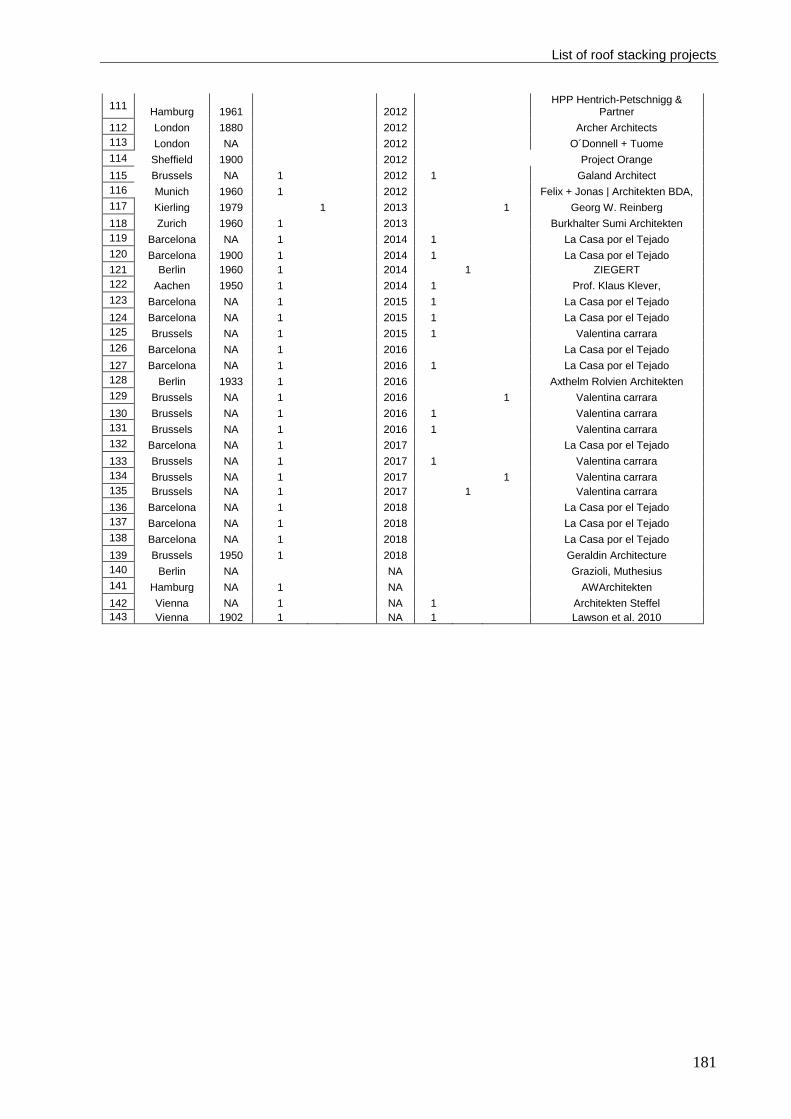
List of roof stacking projects
181
111 Hamburg 1961 2012
HPP Hentrich-Petschnigg & Partner
112 London 1880 2012 Archer Architects
113 London NA 2012 O´Donnell + Tuome
114 Sheffield 1900 2012 Project Orange
115 Brussels NA 1 2012 1 Galand Architect
116 Munich 1960 1 2012 Felix + Jonas | Architekten BDA,
117 Kierling 1979 1 2013 1 Georg W. Reinberg
118 Zurich 1960 1 2013 Burkhalter Sumi Architekten
119 Barcelona NA 1 2014 1 La Casa por el Tejado
120 Barcelona 1900 1 2014 1 La Casa por el Tejado
121 Berlin 1960 1 2014 1 ZIEGERT
122 Aachen 1950 1 2014 1 Prof. Klaus Klever,
123 Barcelona NA 1 2015 1 La Casa por el Tejado
124 Barcelona NA 1 2015 1 La Casa por el Tejado
125 Brussels NA 1 2015 1 Valentina carrara
126 Barcelona NA 1 2016 La Casa por el Tejado
127 Barcelona NA 1 2016 1 La Casa por el Tejado
128 Berlin 1933 1 2016 Axthelm Rolvien Architekten
129 Brussels NA 1 2016 1 Valentina carrara
130 Brussels NA 1 2016 1 Valentina carrara
131 Brussels NA 1 2016 1 Valentina carrara
132 Barcelona NA 1 2017 La Casa por el Tejado
133 Brussels NA 1 2017 1 Valentina carrara
134 Brussels NA 1 2017 1 Valentina carrara
135 Brussels NA 1 2017 1 Valentina carrara
136 Barcelona NA 1 2018 La Casa por el Tejado
137 Barcelona NA 1 2018 La Casa por el Tejado
138 Barcelona NA 1 2018 La Casa por el Tejado
139 Brussels 1950 1 2018 Geraldin Architecture
140 Berlin NA NA Grazioli, Muthesius
141 Hamburg NA 1 NA AWArchitekten
142 Vienna NA 1 NA 1 Architekten Steffel
143 Vienna 1902 1 NA 1 Lawson et al. 2010
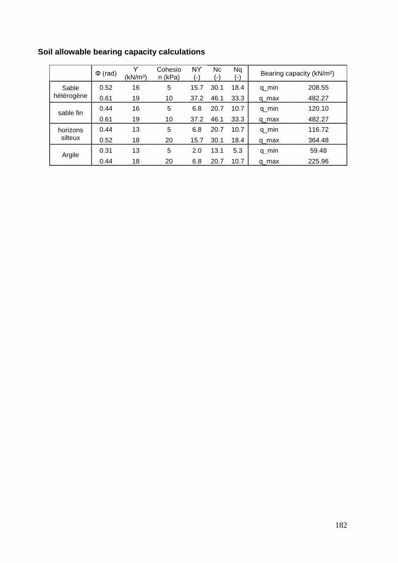
182
Soil allowable bearing capacity calculations
Φ (rad)
ϒ (kN/m³)
Cohesion (kPa)
Nϒ (-)
Nc (-)
Nq (-)
Bearing capacity (kN/m²)
Sable hétérogène
0.52 16 5 15.7 30.1 18.4 q_min 208.55
0.61 19 10 37.2 46.1 33.3 q_max 482.27
sable fin 0.44 16 5 6.8 20.7 10.7 q_min 120.10
0.61 19 10 37.2 46.1 33.3 q_max 482.27
horizons silteux
0.44 13 5 6.8 20.7 10.7 q_min 116.72
0.52 18 20 15.7 30.1 18.4 q_max 364.48
Argile 0.31 13 5 2.0 13.1 5.3 q_min 59.48
0.44 18 20 6.8 20.7 10.7 q_max 225.96

Annex: First Interview
183
FIRST INTERVIEW
Place: La Casa por el Tejado (LCT) Office in Barcelona, Spain
Date & Time: Wednesday 1st of March 2017 @ 16:30
Interviewee: Gerardo Wadel, Director of Research & Development Department at LCT
and Co-founder of Societat Orgànica
MA: Why do you find roof stacking a good solution for urban densification?
GW: In Spain, the urban spaces has been growing between the 19th century and the
21st. The ecological foot print has increased by 40% with all the occupied spaces in its
entire life. Therefore, this created a type of a city seen just as a room to sleep in. The
environmental and social perspective, such as having the access to cultural locations
and services, have faded away. Earlier, there were some experiences with vertical
extensions here in the city before “La Casa Por El Tejado” has started, which raised the
question whether it is possible to find land on the rooftops and offer additional houses in
the in the Eixample district in Barcelona. Earlier studies were made by LCT found more
than 2,800 buildings with the potential to build on their rooftops (Moran, 2015), and 4,000
in whole Spain (this is only according to LCT primary investigations). Another study that
was made by APUR showed that 12% of the parcels in Paris has the potential to be
vertically raised (Alba et al., 2014).
MA: According to the given illustrations, which method do you usually use in your
projects?
GW: Those illustrations are very interesting and allow you to understand quickly the
different ways to do this process, we can identify exactly what is our way! Our method
of construction and load bearing aligns with A1 technique. More specifically similar to
A1.2, which resembles bearing the loads though a load transforming system (a frame of
load distributing system) that is composed of concrete beam along the exterior walls of
the old buildings with crossing steel beams. Figure 4 is taken from LCT office in
Barcelona, which shows a live cross section for the load transforming system through
ring concrete beam in grey and the white steel frames that connects the old building with
the new one.

184
However, we never used the A1.1 method because we do not use 2D linear elements in
the construction such as beams and columns that has the tendency to connect from wall
to wall. Instead, we build full modules that are built on one century old building that needs
an interface where the new loads can be freely distributed.
Generally, the illustration represents a wide part of possible techniques that can be used.
In our case, if we are working in another context different from that in Eixample in
Barcelona, it would have been very different. We can assure now based on our
experience of 10 projects, there is one case where we have to reinforce the existing
structure. That case had an open ground floor due to the commercial use, where there
are four or six columns made of old steel and the receiving the building loads which
arrives from the beams and concentrated on the columns to the soil. And it was a very
strange and unusual case for the transition of the loads, we consider this columns are
not capable to receive an overload. By practice, we never did additional reinforcement
to any of our projects before. However, there was only one case under investigation in
Buenos Aires, where it had two stories and wanted to be extended up to six stories. In
that case our studies showed that a new independent foundation has to be made to
make it possible.
According to the installation techniques graph, we use the onsite assembly of
prefabricated units (B1.1), where the modules arrives onsite 80% finished. But applying
the installations, windows, façade finishing and the upper part of the roof renewable
energy appliances were constructed using the hybrid method (B2.1). On the other hand,
the method of assembling prefabricated elements (B1.2) arrives on site 40% finishes,
and it requires a lot of time to be finished onsite. In our prefabricated units’ assembly
method (B1.1), we use the crane within a very short time, because it cuts the circulation
of the cars and transportation system, where the local government gives only
permissions on Sundays in case of Barcelona. Therefore, time, weather, comfort
aspects and lighting are very important to be adjusted and secured when constructing
onsite. Therefore preparing the modules in the factory resembles the perfect solution for
that case. In addition to the fact that we are working in a part of the city that suits very
much that method, we have wide streets to move a crane and transport a module that
can reach up to 22 meters long.
Annex: First Interview
185
MA: How could you secure the structural stability of the whole building?
GW: We made a brief explanation on how the data and the values of the walls and
bearing capacity are extracted in several publications. (Artes et al., 2017, 2016). The
foundation of the “Eixample” area is made of cross cutting integrated walls that are not
independent. This type of building have walls separated with 3 or 4 meters that makes
a grid in two directions and they work together. The walls are made of handmade bricks,
while the foundations are 2 meters deep made of the same bricks in addition to stones
or the rest of construction works. If the walls in the ground floor is 30 cm width, the
foundation system is estimated to be from 45 or 60 cm width.
The first step is to calculate the strength of the masonry walls. To make this calculation
you may need to cut a part of the wall and measure in the laboratory. Sometimes the lab
measurements are bigger than the calculated ones. Therefore, we use the
measurements that comes from the laboratory, in addition to the coefficient of security
to comply with the construction standards. The second part is through investigating the
foundation of the existing building and know their specifications in terms of dimensions,
material type, state of conservation, etc. Third, we determine the tension of the soil under
the foundation system. Those are categorized under the destructive analyses. For non-
destructive analysis methods, we use some tools that helps us in the investigation such
as the Geo-radar that determines the densities of the materials and approximately
determine the strength of the structure. Another tool is the video cameras with a wire
that inspect cavity walls or spaces that are not accessible without making destructive
analysis. Accordingly, we recalculate the actual strength of the existing building under
investigation.
From a structural point of view we have to highlight one important point that is related to
using the crane to lift the module on the top of the building. The structural forces are
absolutely different when compared to the normal case. This is very important issue that
has to be taken in consideration when making the structural design because a module
that is developed to support vertical forces and loads is different from a module is
designed to be pulled by a crane from 4, 6 or 8 points.
MA: On which bases do you choose the building materials?
GW: One of our main goals when creating that system is to make designs for light weight
modules. The current modules weigh around 330 kg/m2 and this is the third part of the

186
current system that we have now made in situ with bricks, concrete and mortar. We are
in the process of developing a new building system between 250 - 300 kg/m2. It may
seem to be a small difference, however it makes a big difference with multiple units.
Some buildings have strict load bearing capacity, which require a very light weight
building system to be possible to make this extension.
In LCT, we form the flooring slab by using a sheet of cold-formed steel with a layer of
concrete. The steel is used for the tensile forces while the concrete is basically for
acoustic and fire protection. It is very similar to the combination of steel and concrete in
contemporary buildings. The slab can also be made out of timber mainly for three
reasons; first, because it reduces the time needed to form the slab. Second, it is lighter.
Third, it has lower embodied energy and CO2 emissions. However, using timber instead
of concrete is accompanied by an additional cost of 50 euros per square meter.
Senda is a new tool that has been used in LCT and developed specifically for
environmental aspects of the building sector and according to our experience with the
local energy certification. In Spain, there is an obligation to make energy simulation to
the building with a dynamic tool. Every project has to be compared with a reference
building, which is a building with the same boundary conditions complying with the
minimum requirements. In order to achieve the certification, we have to make
modifications on that project to reduce its energy demand.
There is the official one called HULC “Herramienta unificada LIDER-CALENER”, it can
be roughly translated as the unified tool for energy demand limitation and qualification.
In one hand, you have the energy demand and on the other hand you have the energy
study of your project.
For example, in our research and development department, we have a focus on solving
the possible problems associated with thermal bridges resulted from using steel frame
for the module’s skeleton by using timber instead of steel for instance, in addition to the
price, time of construction in factory, thermal quality, and infiltration that are highly taken
in consideration.
MA: How could you integrate the existing building services with the new
extension?
GW: According to our experience this is not a big problem. Regarding the electricity, in
some cases you only need new extensions to and connections to the city grid. Regarding

Annex: First Interview
187
the sewage and piping, it is still useful to make only an extension without any additional
system. However, in some cases, the old system has to be replaced or maintained to
prevent future problems. The main challenge is usually concerning installing an elevator
in a house because it is a very complex operation that may disturb the vertical circulation
of the building, and there may be no place for a lift, so may need to cut part of the stairs
or using the courtyard of the building. We had one case where it was impossible to install
a lift because we didn’t arrive to an agreement with the local government related to
dimensioning of the elevator, therefore we had to abandon the project. However,
extending the stairs is not a big problem. To extend the stairs is not a big problem. In
some cases we need to refine its geometry starting from the last existing floor, because
the size between two stories could be different as you need to correspond to the height
of the neighboring buildings to combine the old with the new part of the building, so this
is a process with new approximations with old, new, neighboring buildings, etc. Briefly,
the main problem is with the dimensioning and geometry but not with the process of the
system itself.
MA: What are the most common social or legislative obstacles that you face?
GW: However, making calculations, prefabrication in the factory, transport them on to
the rooftop and applying finishing may sound complicated, it does not resemble a big
problem or disadvantage. What stands against Roof Stacking is that it is a very long
process especially when it comes to the obligation of making agreement with a lot of
people. Due to the lack of experience from technicians, neighbors and citizen, the
process faces more obstacles specifically with the lack of specific construction and urban
standards for this special type of housing. In some cases, people think that this is an
illegal process and it is associated with a lot of risks and with minor advantages.
However, the addition of more stories is considered to be a part of the story of
architecture and it is not something new. In addition, some buildings have a lot of
problems that should be fixed prior to initiating an additional floor, which is considered
as a part of the whole process. Sometimes it is too expensive that it wouldn’t be feasible
even after a successful rental or selling of the new flats. There are many limitations that
hinders roof stacking basically within the current urban standards in how to calculate the
maximum height, volume or area that you are allowed to build within. For example, if a
window is opened towards a neighboring building, this resembles a restriction to that
building to be raised by the fact of that there is a window opened on that side. After

188
fulfilling the urban and regulative standards, the load bearing capacity of the existing
building comes in the second phase. We kept in mind if that building is interesting to
offer an amount of money to buy that right. Other things like legal aspects and urban
standards, you can find up to 20 people with a right of property, so we need a lot of time
and effort to make an agreement with all those people with different interests, ambitions,
relationships and fears which are not sure for them, such as risk of collapse and security.

Annex: Second Interview
189
SECOND INTERVIEW
Place: Architecturbüro Reinberg Office in Vienna, Austria
Date & Time: Tuesday 7th of March 2017 @ 13:30
Interviewee: Georg W. Reinberg, Director of Architecturbüro Reinberg ZT GmbH
MA: Why do you find roof stacking a good solution for urban densification?
GWR: In the case study of Kierling, it was a form of densification. It was taken from an
ecological point of view to use an existing building in a more intensive way. In that case
we had to do a high level of retrofitting for the building. Since, the rents were limited and
as a house owner he has no right to raise the rent on the inhabitants and therefore the
budget was very limited. Thus, the densification of this project was taken from an
economic point of view. It was a way to finance the project by renting or selling the
additional apartments on the rooftop.
The land is very limited in the cities, and it is very expensive when it is found. Therefore,
it is a good idea to building on the existing building stock. In Vienna particularly, the
population is growing very fast. I find it applicable to other cities however every situation
is different. However, it is more urgent to increase density in cities with growing
population. In Vienna there is a lot of movement from small towns to bigger cities and
also from other countries to the major cities.
MA: According to the given illustrations, which method do you usually use in your
projects?
GWR: The illustrations aids in decision making as I believe that architects have to know
the different possibilities for roof stacking because every house would have a different
circumstances. Therefore, you have to make all your decisions and how to interfere
based on every situation.
The illustration represents different techniques depending on the actual condition of the
existing building. For example, in some cases you have restriction on the boarders of
the construction as shown in Figure A, which is similar to method A1.2 however with no
loads transformation through a platform but through metal beams instead. That method
represents more Figure B as a load distributing system where you can locate your
columns anywhere on it.

190
Figure A: Load distribution through metal
beams
Figure B: Load distribution through
platform
Another way of bearing the loads from the new extension is through wooden panels. It
works as shown in Figure C as you can load each panel on the existing building’s
columns and it works as shear walls but in wood. In between the wood lattices, doors
can be opened. We used wood panels in the case of Kierling in addition to steel beams
at some parts.
Figure C: Load distribution through wooden panels
As shown in the pictures, wall panels rests between two bearing walls. Some steel
beams were added for better redistribution of the loads. However, the staircase had to
be made completely in concrete for fire safety reasons.
In the case of kierling, load bearing panels were fabricated and assembles onsite. The
cuts for the windows were made in advance in the factory, where the windows were
installed in a later phase, which is more equivalent to B2.1 technique.
MA: How could you secure the structural stability of the whole building?
GWR: Every house is different. You will need seriously to investigate everything in each
building to define how the structure functions in the building. We have specialized civil
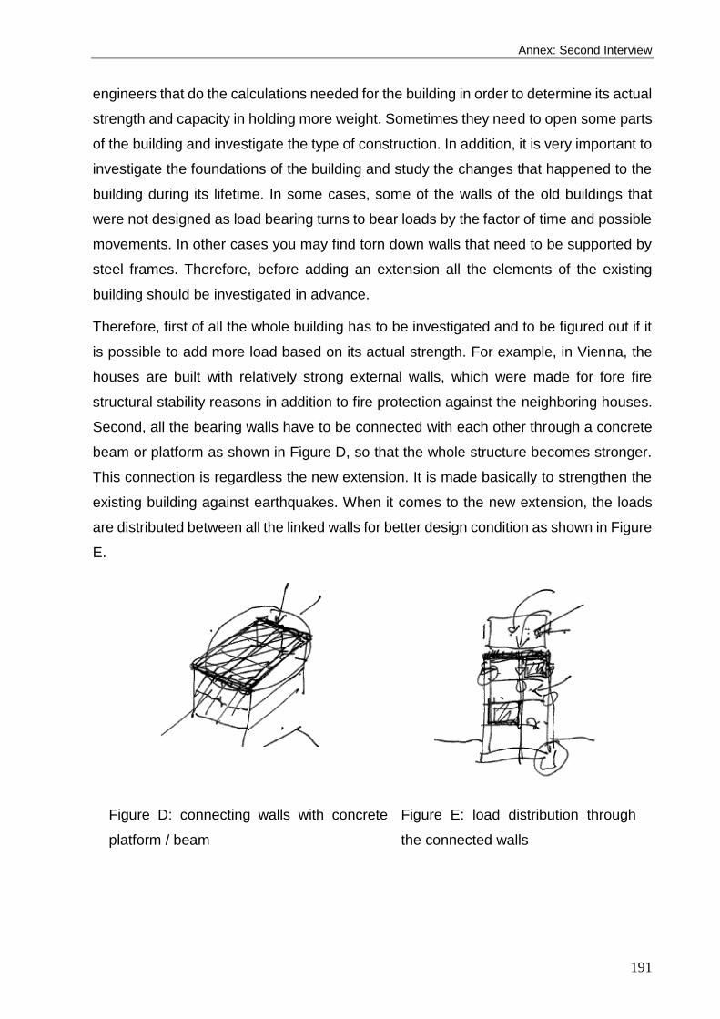
Annex: Second Interview
191
engineers that do the calculations needed for the building in order to determine its actual
strength and capacity in holding more weight. Sometimes they need to open some parts
of the building and investigate the type of construction. In addition, it is very important to
investigate the foundations of the building and study the changes that happened to the
building during its lifetime. In some cases, some of the walls of the old buildings that
were not designed as load bearing turns to bear loads by the factor of time and possible
movements. In other cases you may find torn down walls that need to be supported by
steel frames. Therefore, before adding an extension all the elements of the existing
building should be investigated in advance.
Therefore, first of all the whole building has to be investigated and to be figured out if it
is possible to add more load based on its actual strength. For example, in Vienna, the
houses are built with relatively strong external walls, which were made for fore fire
structural stability reasons in addition to fire protection against the neighboring houses.
Second, all the bearing walls have to be connected with each other through a concrete
beam or platform as shown in Figure D, so that the whole structure becomes stronger.
This connection is regardless the new extension. It is made basically to strengthen the
existing building against earthquakes. When it comes to the new extension, the loads
are distributed between all the linked walls for better design condition as shown in Figure
E.
Figure D: connecting walls with concrete
platform / beam
Figure E: load distribution through
the connected walls
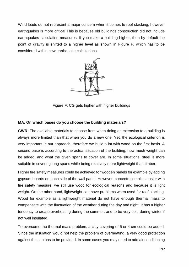
192
Wind loads do not represent a major concern when it comes to roof stacking, however
earthquakes is more critical This is because old buildings construction did not include
earthquakes calculation measures. If you make a building higher, then by default the
point of gravity is shifted to a higher level as shown in Figure F, which has to be
considered within new earthquake calculations.
Figure F: CG gets higher with higher buildings
MA: On which bases do you choose the building materials?
GWR: The available materials to choose from when doing an extension to a building is
always more limited than that when you do a new one. Yet, the ecological criterion is
very important in our approach, therefore we build a lot with wood on the first basis. A
second base is according to the actual situation of the building, how much weight can
be added, and what the given spans to cover are. In some situations, steel is more
suitable in covering long spans while being relatively more lightweight than timber.
Higher fire safety measures could be achieved for wooden panels for example by adding
gypsum boards on each side of the wall panel. However, concrete complies easier with
fire safety measure, we still use wood for ecological reasons and because it is light
weight. On the other hand, lightweight can have problems when used for roof stacking.
Wood for example as a lightweight material do not have enough thermal mass to
compensate with the fluctuation of the weather during the day and night. It has a higher
tendency to create overheating during the summer, and to be very cold during winter if
not well insulated.
To overcome the thermal mass problem, a clay covering of 5 or 4 cm could be added.
Since the insulation would not help the problem of overheating, a very good protection
against the sun has to be provided. In some cases you may need to add air conditioning

Annex: Second Interview
193
to comply with the strict building regulation in providing indoor thermal comfort; however
it would be a shame to do it in a housing project. In Austria the temperature has
increased by two degrees, which is relatively higher than other countries.
For the case study of Wollzeile, the actual building was in a very good condition in term
of the used bricks and mortar. The better quality the higher strength is given to the
building. As a matter of fact, buildings that were owned by the rich used a better mortar
that that were owned by the poor. Thus, the quality of the building did count in many
cases on either it was built in a rich or poor area.
Based on these conditions, we were able to use concrete in the extension for two
reasons; first, it was meant to link between the different walls of the building. Second,
the concrete was used within the active strategy of the building and to avoid overheating
problems in the summer. Water pipes were installed in the concrete as shown in Figure
G. It uses the water under the building (there used to be a river under this land plot,
which has been covered) by taking cold water and running it indirectly (through heat
exchange) through the pipes in the concrete during the summer to cool down the
building. While in winter, the water is connected to a heat pump that warms the water
before going through the columns. The whole active system using underground water
was integrated in the whole building and in the office. A false ceiling was made in the
offices where there is cold water loops to cool down the offices.
Figure G: Active concrete columns using underground water
194
MA: How could you integrate the existing building services with the new
extension?
GWR: Very often they are needed to be exchanges that being renovated. It give sense
to renovate an old building before adding a new floor to it, otherwise it is like giving a
terrible house a new attic. Sometimes it is difficult to integrate new services with old ones
that makes it more challenging. In Kierling we had to change everything including the
old HVAC system, however we faced some design restrictions related to the existing
pipes that we have to link with.
MA: What are the most common social or legislative obstacles that you face?
GWR: The social obstacle is the most common one when doing roof stacking because
usually people live in the building that you are stacking or renovating. Such problem
could be solved through social organizations. For example in Kierling, we spoke with
every single family before we start. We needed to be granted an approval prior to design
and construction. Every family was visited with a social worker and technicians from our
office. We had to listen to them and documented everything.
On the other hand in the case of Wollziele, we didn’t face the same obstacle because
the building was empty except with a shop in the ground floor, which was much easier
to handle.
Another obstacle is related to regulatory restrictions, because the design should be
approved from the buildings commission that is concerned with protecting the old
environment of the city, which is not objective in many cases and it is based on subjective
process by getting an approval from a certain jury that you have to take their signature
and licence to build.
Annex: Third Interview
195
THIRD INTERVIEW
Place: Atelier d’Architecture Galand Office in Brussels, Belgium
Date & Time: Monday 20th of March 2017 @ 14:30
Interviewee: Antoine Galand, Director of Atelier d’Architecture Galand
MA: Why do you find roof stacking a good solution for urban densification?
AG: In my opinion, I wouldn’t go for urban densification as the first answer because the
cities are already dense. And it would be more efficient to demolish old houses and build
higher ones if it is meant to increase the density of the cities. Yet, from an ecological
point of view, in Brussels there are a lot of projects that regenerates the rooftops of the
existing buildings, either by making green roofs with productive crops or by building over
the rooftops, however the latter option wouldn’t be simple especially for old buildings.
On the other hand, there are many office buildings that are made in concrete, where it
is simpler to build dwellings on their rooftops.
However, in some cases where it is needed to increase the density of the plot with being
able to evacuate the buildings from its inhabitants, roof stacking is inevitable. For
example, the project “Sleep well in the sky” there was no other option than building on
the rooftop of the existing hostel. Another option that we had was to build in the
courtyard, but it was more pleasant to keep the courtyard for public gatherings and for
outdoor activities.
However, we cannot increase very much for two reasons; the first reason is because the
basement was very bad and the neighborhood was not very high, so we couldn’t go
higher. In Brussels you have specific rules that says that you can go as high as your
neighbor but not more than 3 meters than the other neighbor.
MA: According to the given illustrations, which method do you usually use in your
projects?
AG: In the case of “Sleep well in the sky”, A1.2 method was used more or less. We used
also a part of method A2, because in our case study we made an extension on two
different buildings at the same time. The first building was built in the 80th, while the other
was built in the beginning of the year 2000.

196
The newer building was made of concrete walls, strong façades and foundations,
therefore we could build on it easily. On the other hand, the older building was in bad
conditions with a tendency to move around 15cm from the other building, and it was
made of RC skeleton and façade made out of bricks. We had to respect the rhythm of
columns of the older building for the first raised floor, however in the second raised floor
the structure was made completely in wood and we had more flexibility in the bearing
load design.
Regarding method A3, I think it is very expensive to make additional reinforcements to
the building, however, it would be very interesting because there is the ability to keep
the building as is and use its extended vertical space. There was a challenge to access
the building with the building materials. So, the courtyard behind was used for
assembling the 2D elements coming from the factory and lift it on the roof. The courtyard
wasn’t very big, therefore the fabricated elements were not very big, they were in the
size of fragmented building envelope. Thus, it is more equivalent to the method
illustrated under the B2.1.
The construction process that had to take place while the hostel was functioning. This
process was complex in terms of managing the different stockholders in a perfect timing.
There were different enterprises working on it. Thus, there were a project manager to
connect everybody, we worked a lot with him. It was one person who was the director of
the construction enterprise.
MA: How could you secure the structural stability of the whole building?
AG: The level of challenges we faced in this project differed according to each building
of the two buildings we had onsite. The first part related to the newer building was quite
easy to design and to structurally solve. That part included the rooms and the corridor.
On the other hand, the second part was much harder and more complicated to make its
architectural plans, which included mainly the patio. We had to install big steel beams
that connect the RC columns of the older building, and accordingly the new loads are
settled on that beam. However, to use steel in Belgium, it has to be protected against
fire. Therefore all steel beams were covered and protected for a safe usage. In addition,
within out designs, we had to guarantee that the new extension can move according to
the natural movement of the existing building independently. The new extension was
divided mainly into two parts in the architectural plans as shown in Figure H. The main
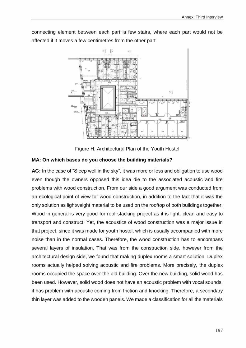
Annex: Third Interview
197
connecting element between each part is few stairs, where each part would not be
affected if it moves a few centimetres from the other part.
Figure H: Architectural Plan of the Youth Hostel
MA: On which bases do you choose the building materials?
AG: In the case of “Sleep well in the sky”, it was more or less and obligation to use wood
even though the owners opposed this idea die to the associated acoustic and fire
problems with wood construction. From our side a good argument was conducted from
an ecological point of view for wood construction, in addition to the fact that it was the
only solution as lightweight material to be used on the rooftop of both buildings together.
Wood in general is very good for roof stacking project as it is light, clean and easy to
transport and construct. Yet, the acoustics of wood construction was a major issue in
that project, since it was made for youth hostel, which is usually accompanied with more
noise than in the normal cases. Therefore, the wood construction has to encompass
several layers of insulation. That was from the construction side, however from the
architectural design side, we found that making duplex rooms a smart solution. Duplex
rooms actually helped solving acoustic and fire problems. More precisely, the duplex
rooms occupied the space over the old building. Over the new building, solid wood has
been used. However, solid wood does not have an acoustic problem with vocal sounds,
it has problem with acoustic coming from friction and knocking. Therefore, a secondary
thin layer was added to the wooden panels. We made a classification for all the materials
198
according to NIBE, we had to do that for the Ecobatisseurs. Each material used on site
had to be justified from an ecological point of view.
MA: How could you integrate the existing building services with the new
extension?
AG: In terms of staircase and elevators, it is impossible to change their places and you
have to respect it in the design process of the hostel. However, regarding the heater of
the existing building, it was three times smaller than what we needed from a capacity
and an ecological point of view.
Thus, there was a decision to include a new heater, ventilation system and water heater
beside the existing one. All the new system installed was for the existing building and
the new extension at the same time. We could use the old pipes of the existing building,
however, it had to be integrated with the new HVAC system. The first step that we had
to keep the old system as is, because there were users already who needed hot water
and heating system. The old system consisted of two heaters, we stopped one of them
in the good season in summer, and then we just added the new system and linked them
together. There was only one room for all the HVAC system in the old building which
was not sufficient to include the space for solar heater, heater and ventilation system.
Therefore, a new space was created especially for the ventilation system for the whole
building, which was a big challenge to include it in the whole building. It had to take huge
spaces in the corridor to be able to let the ducts through the corridors, which has ended
up with 2.5 meter height. It was unfortunately not the optimum height however there was
no other option. In general there is a huge part of the building was dedicated for the
technic. That was one of the main problem that we find in the building. The size of the
technic is three times bigger than the one that existed which was for the heater,
cogeneration and solar heater. Regarding the electricity, there was no problem at all.
MA: What are the most common social or legislative obstacles that you face?
AG: It is different from who is rating, is it the architect or the project owner. Generally
talking, it is always difficult to deal with the neighborhood. In this project we had to deal
with it before getting with the work itself. We were all the time under stress. But because
we were dealing with the ministry for the hostel directly it was easier to get things done,
which is different from the ministry of urban.

Annex: Third Interview
199
In Belgium there is a social consultation that has to be involved in the decision making
of the project, where the neighbors are there too and where the negotiations take place.
As we worked with Ecobatisseurs, there were people who came and visit the work space
frequently to follow up the progress, materials installations, etc. Therefore people were
very interested by this type of construction at the end.

200

Annex: Questionnaire
201
Questionnaire
1- What is the construction techniques (load bearing and installation) that you have used
according to the Figures 1 & 2? If not any, what method did you use to connect the roof
extension to the existing building?
2- What are the main building materials that are used in the construction (in terms of (a)
main structure elements and (b) building envelope)? & Why?
3- Was keeping your new extension light-weighted one of your aims? What strategies
did you follow to achieve that aim? How could you secure the structural stability of the
whole building?
4- Which of the following challenges do you usually face when making roof extensions?
(You can add other points that you see more challenging) & how do you overcome those
challenges?
allowable bearing capacity of the soil
strength of the existing structure & foundation
wind & seismic loads considerations
5- What are the main design performance that you considered during design and
construction (e.g. in terms of achieving passive house standard, thermal comfort,
reducing energy consumption, Life Cycle Assessment – LCA, etc.) and how could you
achieve them?
6- What are the most common legislative obstacles that you face (e.g. urban policies,
right to light, parking, fire regulations, etc.)? & how did you manage them?
7- How could you integrate the existing building services with the new extension (e.g.
vertical circulation, water, sewage, electricity, etc.)?
8- In your opinion, when is it impossible to apply roof stacking (e.g. structural, legislative,
financial reasons, etc.), Could you give some examples?

202

203
Glossary
Table A: Economic category DMFs description
Economic category Description
C1: Labor Cost The cost of skilled labors, supervisors, site managers, etc.
C2: Materials Cost The cost of building materials
C3: Transportation Cost The cost of transporting materials to the site and loading on the rooftop
C4: Maintenance, defects & damages The cost of maintenance or damages onsite
C5: Life cycle & disposal The cost associated with demolition and waste treatment
C6: Post occupancy operational cost E.g. the cost needed for heating, cooling and lighting
C7: Offsite construction time Preconstruction phase including planning, designing, and manufacturing
C8: Onsite construction time The time needed to accomplish construction onsite
C9: Coordination & transportation time The time consumed in coordination and transporting building materials
C10: Time intervals between tasks The time needed for every task and the transition period between tasks
C11: Effect of weather conditions Possible interruptions in the construction process due to weather
C12: Quality of prefabricated elements The quality of building elements and outcome
C13: Integration with building’s service Integrating new construction with building’s services & HVAC system
C14: Dimensional constrains E.g. street widths, urban context, building’s height and neighboring buildings
C15: Accessibility to worksite area Access to the site including lifting process and storing building materials
C16: Ease of management & supervision Construction management and work flow process
Table B: Social category DMFs description
Social category Description
S1: Workers health and safety The risk of injury in dangerous situations during construction
S2: Vandalism & loss of materials The probability of losing materials onsite
S3: Design flexibility & constructability Ease of construction and applying modifications on site
S4: Aesthetic product The quality of the final architectural product and finishing
S5: Supplier availability & reliability Reliable supplier for building materials or offsite construction products
S6: Availability of skilled labors The demand of skilled labor including supervisors and site managers
S7: Having less labors onsite Unnecessary added tasks during construction
S8: Noise generation Neighbors disturbance and causing noise
S9: Avoiding site disruption Impact of construction activities on surrounding neighbors and traffic
Table C: Environmental category DMFs description
Environmental category Description
E1: Waste production & management The amount of wasted materials leftover during and after construction
E2: Pollution generation CO2 emissions and dust generation during construction
E3: Water consumption The amount of water needed onsite for construction
E4: Circularity The opportunity to reuse building elements in other construction
E5: Environmental Impact Building materials’ impact on the environment (e.g. GHG & embodied energy)
E6: Thermal mass of building materials The tendency of the building material to store heat
E7: Acoustic impedance The resistance of building materials to sound
E8: Energy consumption Energy consumed by the end user inhabitant
E9: Durability The long usability of building elements and the whole construction
E10: Weight of building materials Building materials weight (e.g. Kg/m2) related to structural safety
E11: Structural capacity The structural characteristics (tension, compression, shear, etc.)
E12: Fire resistance The resistance of building materials to fire

204