Demonstration at FLASH - CERN. Waldemar Koprek, ... ATMEGA 1281 microcontroller with dedicated...
27
Waldemar Koprek, DESY LLRF09, Tsukuba, Japan, 2009 ATCA-based LLRF System for XFEL Demonstration at FLASH Waldemar Koprek, DESY for the XFEL LLRF team
Transcript of Demonstration at FLASH - CERN. Waldemar Koprek, ... ATMEGA 1281 microcontroller with dedicated...

Waldemar Koprek, DESY LLRF09, Tsukuba, Japan, 2009
ATCA-based LLRF System for XFELDemonstration at FLASH
Waldemar Koprek, DESYfor the XFEL LLRF team

Waldemar Koprek, DESY LLRF09, Tsukuba, Japan, 2009
Outline
• Introduction to ATCA
• LLRF System for the European XFEL
• ATCA-based LLRF System
• Demonstration at FLASH

Waldemar Koprek, DESY LLRF09, Tsukuba, Japan, 2009
ATCA Standardand
xTCA for Physics

Waldemar Koprek, DESY LLRF09, Tsukuba, Japan, 2009
ATCA Standard
PICMG 3.0 – Advanced Telecommunications Computer Architecture
PICMG AMC.0 – Advanced Mezzanine Card

Waldemar Koprek, DESY LLRF09, Tsukuba, Japan, 2009
xTCA for Physics
PICMG xTCA for Physics Coordinating Committee• xTCA for physics objectives:
– Extensions to specifications– Guidelines– Open source solutions– Approval by PICMG membership vote– Collaborate with industry for vendor support– Building on existing xTCA base under PICMG rules
http://www.picmg.org/pdf/PICMG_Physics_Public_Web_Update_061209_R5-3.pdf

Waldemar Koprek, DESY LLRF09, Tsukuba, Japan, 2009
Industrial LLRF in xTCA Standard

Waldemar Koprek, DESY LLRF09, Tsukuba, Japan, 2009
ATCA Design for LLRF

Waldemar Koprek, DESY LLRF09, Tsukuba, Japan, 2009
XFEL Overview

Waldemar Koprek, DESY LLRF09, Tsukuba, Japan, 2009
Architecture of the LLRF System for XFEL

Waldemar Koprek, DESY LLRF09, Tsukuba, Japan, 2009
Decision for ATCA
• Future LLRF systems will require simultaneous data acquisition of up to 100 fast ADC channels at sampling rates of around 100 MHz and real time signal processing within a few hundred nanoseconds.
• Also desirable are modularity and scalability of the design as well as compatibility with accelerator instrumentation needs including the control system.
• All these requirements can be fulfilled with the new telecommunication standard ATCA

Waldemar Koprek, DESY LLRF09, Tsukuba, Japan, 2009
Architecture of LLRF System
RF signalsProbes, Pfor, Pref
LO
DWC x24
ADCIF signals
x8
Local preprocessing
DACRF Drive SignalMO
VM
x4 – Probes, Pfor, Pref
Timing module
Optical communication
Low LevelApplications
LLRFController

Waldemar Koprek, DESY LLRF09, Tsukuba, Japan, 2009
Hardware Design

Waldemar Koprek, DESY LLRF09, Tsukuba, Japan, 2009
Configuration of LLRF in ATCA Crate

Waldemar Koprek, DESY LLRF09, Tsukuba, Japan, 2009
ATCA Carrier with AMC slots and RTM
RTM
1.3 GHzRF Inputs
Down-convertersTo 25 MHz IF
105 MHz 14 bit 8 Ch
COTS ADC’s
Stacked 1-wideAMC ADC’s &
IO AMC’s, connectors
TUWG105, Dariusz Makowski – “ATCA Carrier Board for LLRF System of XFEL Accelerator”

Waldemar Koprek, DESY LLRF09, Tsukuba, Japan, 2009
ATCA Demonstration at FLASH

Waldemar Koprek, DESY LLRF09, Tsukuba, Japan, 2009
Demonstration Goals
Objective Comment
Analog IO Demonstrate the noise added from entrance to rear transition module through Zone 3 and carrier to AMC module is not degraded
Communication links Demonstrate that the scheme of Low Latency Links, PCIe and GbE is functional.
Operation in accelerator environment
Demonstrate that the ATCA based LLRF is functional in the noisy accelerator environment.
Rear transition module Demonstrate the concept of rear transition modules with downconverters
Timing distribution Demonstrate timing distribution functionality
Timing jitter Demonstrate that the measured timing jitter is adequate for LLRF control.
IPMI Demonstrate the IPMI implementation.

Waldemar Koprek, DESY LLRF09, Tsukuba, Japan, 2009
ACC4/5/6 at FLASHACC4/5/6 = 24 cavities

Waldemar Koprek, DESY LLRF09, Tsukuba, Japan, 2009
ATCA Configuration at FLASH
Waldemar Koprek, DESY LLRF09, Tsukuba, Japan, 2009
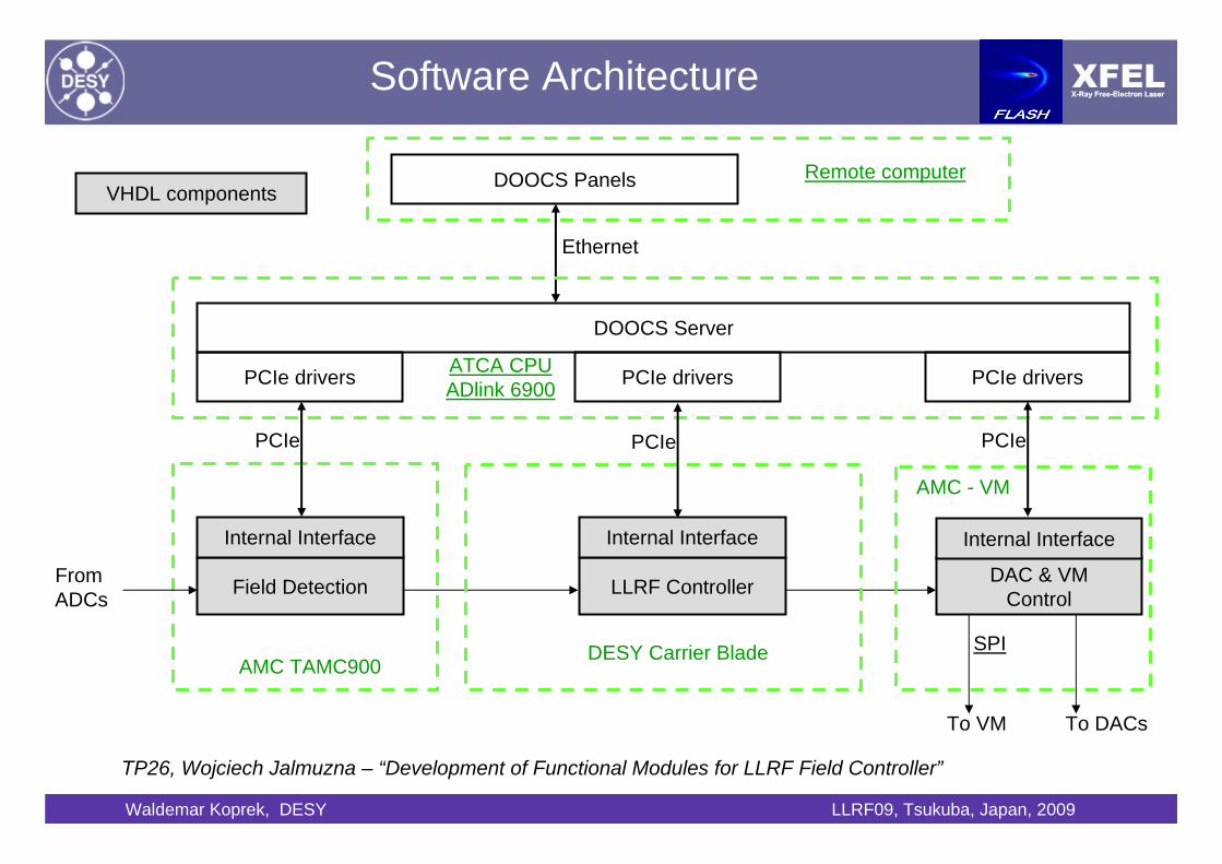
Software Architecture
Field Detection DAC & VMControl
PCIe drivers
PCIe
DOOCS Server
DOOCS Panels
Ethernet
From ADCs
SPI
To VM To DACs
ATCA CPUADlink 6900
Remote computer
AMC TAMC900
AMC - VM
Internal Interface
VHDL components
LLRF Controller
DESY Carrier Blade
Internal Interface
PCIe drivers PCIe drivers
PCIe PCIe
Internal Interface
TP26, Wojciech Jalmuzna – “Development of Functional Modules for LLRF Field Controller”

Waldemar Koprek, DESY LLRF09, Tsukuba, Japan, 2009
Intelligent Platform Management Interface (IPMI)
IPMCATMEGA 1281
microcontroller withdedicated
management hardware
Management of ATCA carrier blades,Management of AMC modules,Monitoring of ATCA health (diagnostics),E-Keying for PCIe, Gb Ethernet and user defined Low Latency Connection,Monitoring of temperature, power supply, clocks, etc...

Waldemar Koprek, DESY LLRF09, Tsukuba, Japan, 2009
Set-up at FLASH with 2 carrier boards
ATCA CPU Blade
ATCA Carrier Blade
ADC (AMC module)
Timing Module
Vector Modulator

Waldemar Koprek, DESY LLRF09, Tsukuba, Japan, 2009
Set-up in Lab with 4 Carrier Blades

Waldemar Koprek, DESY LLRF09, Tsukuba, Japan, 2009
Operator Interface

Waldemar Koprek, DESY LLRF09, Tsukuba, Japan, 2009
Amplitude and Phase Control
0 200 400 600 800 1000 1200 1400 1600 1800 20000
0.5
1
1.5
2
2.5
3
3.5
4 x 10⁴
time [us]
ampl
itude
[a.u
.]
Feed ForwardFeedback gain = 1Feedback gain = 45Feedback gain = 75
500 550 600 650 700 750 800 850 9003.45
3.5
3.55
3.6
3.65
3.7
3.75
3.8 x 10⁴
time [us]
ampl
itude
[a.u
.]
Feed ForwardFeedback gain = 1Feedback gain = 45Feedback gain = 75
500 550 600 650 700 750 800 850 900-10
-8
-6
-4
-2
0
2
4
6
8
time [us]
phas
e [d
eg]
Feed ForwardFeedback gain=1Feedback gain=45Feedback gain=75
0 200 400 600 800 1000 1200 1400 1600 1800 20000
0.2
0.4
0.6
0.8
1
1.2
1.4
1.6
1.8
2 x 10⁵
time [us]
ampl
itude
[a.u
.]
Feed ForwardFeedback gain = 1Feedback gain = 45Feedback gain = 75
Amplitude
Phase
Drive signalΔA/A ~1e-3 (rms)
Δφ ~0.1 deg. (rms)
Amplitude

Waldemar Koprek, DESY LLRF09, Tsukuba, Japan, 2009
Crosstalk, Noise and Timing Jitter
ADC1 ADC2 ADC3 ADC4 ADC5 ADC6 ADC7 ADC8
ADC1 on -67.87 -48.14 -66.86 -66.39 -73.71 -69.90 -67.11 -71.38
ADC2 on -48.35 -67.79 -68.14 -74.08 -69.35 -71.00 -67.86 -72.67
ADC3 on -59.51 -66.47 -68.09 -52.43 -66.08 -70.39 -66.98 -72.60
ADC4 on -65.52 -69.55 -49.03 -68.03 -68.82 -69.81 -66.69 -70.78
ADC5 on -73.27 -73.27 -67.81 -69.82 -66.44 -44.35 -63.30 -69.77
ADC6 on -2.92 -0.45 0.56 -3.24 17.30 -8.12 4.08 8.28
ADC7 on -76.22 -70.18 -69.39 -77.31 -65.34 -70.27 -68.47 -45.76
ADC8 on -70.80 -63.62 -62.15 -69.65 -67.48 -62.79 -52.15 -64.50
Preliminary Performance Data • Channel isolation >80 dB @50MHz
(presently limited by downconverter)• Noise < 200 μV (rms)
consistent with 14-bit ADC, 200 MHz bandwidth• Timing jitter < 15 ps (rms) @ 81 MHz
(upper limit, could be dominated by RF
0 5 10 15 20 25 30 35 40-140
-120
-100
-80
-60
-40
-20
0
freq. [MHz]
ampl
itude
[dB
FS]
FS = -4.84dBFS
0 30 60 90 120 150 180 210 240 270 300-44
-43
-42
-41
-40
-39
-38
-37
-36
-35
time[us]
deg
Cavity phase measurement
300 us open loop
Phase measurement
Spectral noise density

Waldemar Koprek, DESY LLRF09, Tsukuba, Japan, 2009
Conclusion
• The demonstration of the ATCA-based LLRF system at the FLASH user facility has verified that this standard can be employed for a wide range of physics applications:• ATCA for large scale and high performance systems• μTCA for low cost instrumentation needs• and combinations of these standards
• Although standard is quite new commercial components and even complete systems are already available for physics applications.• Several physics labs are already using or evaluating the
ATCA and μTCA standard
• xTCA for physics standardization effort between labs and industry will release first specifications in 2010 and should lead to commercially available products within 1-2 years.

Waldemar Koprek, DESY LLRF09, Tsukuba, Japan, 2009
Project Participants• Technical University of Lodz, DMCS, Poland
– Wojciech Cichalewski– Grzegorz Jablonski– Wojciech Jalmuzna– Tomasz Kozak– Tomasz Kucharski– Dariusz Makowski– Adam Piotrowski– Sergiusz Szachowalow– Jan Wychowaniak
• Warsaw University of Technology, ISE, Poland– Krzysztof Czuba– Samer Bou Habib– Lukasz Butkowski
• Institute of Nuclear Problems, Swierk, Poland– Jaroslaw Szewinski
• DESY, Hamburg, Germany– Mariusz Grecki– Tomasz Jezynski– Maciej Kudla– Frank Ludwig– Stefan Simrock– Henning Weddig