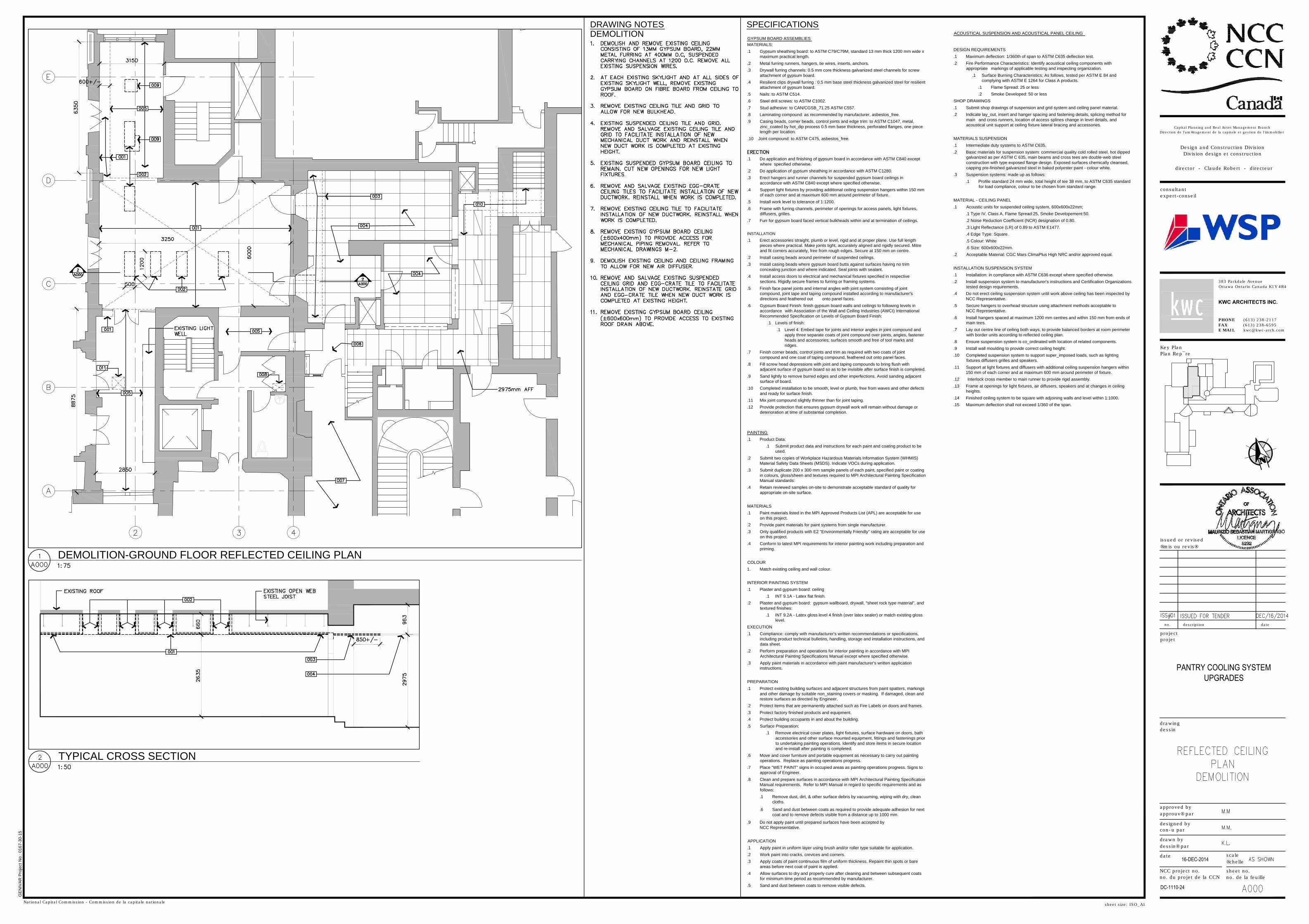
DEMOLITION-GROUND FLOOR REFLECTED CEILING PLAN
11
GENIVAR Project No.: 0167-30-15 sheet no. no. de la feuille NCC project no. no. du projet de la CCN scale pFKHOOH date drawn by GHVVLQp SDU designed by FRQoX SDU approved by DSSURXYp SDU drawing dessin project projet issued or revised pPLV RX UHYLVp sheet size: ISO_A1 no. description date DC-1110-24 National Capital Commission - Commission de la capitale nationale 16-DEC-2014 PANTRY COOLING SYSTEM UPGRADES Key Plan 3ODQ 5HSqUH consultant expert-conseil director - Claude Robert - directeur Design and Construction Division Division design et construction Capital Planning and Real Asset Management Branch 'LUHFWLRQ GH ODPpQDJHPHQW GH OD FDSLWDOH HW JHVWLRQ GH OLPPRELOLHU 383 Parkdale Avenue Ottawa Ontario Canada K1Y 4R4 KWC ARCHITECTS INC. PHONE (613) 238-2117 FAX (613) 238-6595 E MAIL [email protected] DEMOLITION-GROUND FLOOR REFLECTED CEILING PLAN GYPSUM BOARD ASSEMBLIES MATERIALS; .1 Gypsum sheathing board: to ASTM C79/C79M, standard 13 mm thick 1200 mm wide x maximum practical length. .2 Metal furring runners, hangers, tie wires, inserts, anchors. .3 Drywall furring channels: 0.5 mm core thickness galvanized steel channels for screw attachment of gypsum board. .4 Resilient clips drywall furring : 0.5 mm base steel thickness galvanized steel for resilient attachment of gypsum board. .5 Nails: to ASTM C514. .6 Steel drill screws: to ASTM C1002. .7 Stud adhesive: to CAN/CGSB_71.25 ASTM C557. .8 Laminating compound: as recommended by manufacturer, asbestos_free. .9 Casing beads, corner beads, control joints and edge trim: to ASTM C1047, metal, zinc_coated by hot_dip process 0.5 mm base thickness, perforated flanges, one piece length per location. .10 Joint compound: to ASTM C475, asbestos_free. .1 Do application and finishing of gypsum board in accordance with ASTM C840 except where specified otherwise. .2 Do application of gypsum sheathing in accordance with ASTM C1280. .3 Erect hangers and runner channels for suspended gypsum board ceilings in accordance with ASTM C840 except where specified otherwise. .4 Support light fixtures by providing additional ceiling suspension hangers within 150 mm of each corner and at maximum 600 mm around perimeter of fixture. .5 Install work level to tolerance of 1:1200. .6 Frame with furring channels, perimeter of openings for access panels, light fixtures, diffusers, grilles. .7 Furr for gypsum board faced vertical bulkheads within and at termination of ceilings. INSTALLATION .1 Erect accessories straight, plumb or level, rigid and at proper plane. Use full length pieces where practical. Make joints tight, accurately aligned and rigidly secured. Mitre and fit corners accurately, free from rough edges. Secure at 150 mm on centre. .2 Install casing beads around perimeter of suspended ceilings. .3 Install casing beads where gypsum board butts against surfaces having no trim concealing junction and where indicated. Seal joints with sealant. .4 Install access doors to electrical and mechanical fixtures specified in respective sections. Rigidly secure frames to furring or framing systems. .5 Finish face panel joints and internal angles with joint system consisting of joint compound, joint tape and taping compound installed according to manufacturer's directions and feathered out onto panel faces. .6 Gypsum Board Finish: finish gypsum board walls and ceilings to following levels in accordance with Association of the Wall and Ceiling Industries (AWCI) International Recommended Specification on Levels of Gypsum Board Finish: .1 Levels of finish: .1 Level 4: Embed tape for joints and interior angles in joint compound and apply three separate coats of joint compound over joints, angles, fastener heads and accessories; surfaces smooth and free of tool marks and ridges. .7 Finish corner beads, control joints and trim as required with two coats of joint compound and one coat of taping compound, feathered out onto panel faces. .8 Fill screw head depressions with joint and taping compounds to bring flush with adjacent surface of gypsum board so as to be invisible after surface finish is completed. .9 Sand lightly to remove burred edges and other imperfections. Avoid sanding adjacent surface of board. .10 Completed installation to be smooth, level or plumb, free from waves and other defects and ready for surface finish. .11 Mix joint compound slightly thinner than for joint taping. .12 Provide protection that ensures gypsum drywall work will remain without damage or deterioration at time of substantial completion. PAINTING .1 Product Data: .1 Submit product data and instructions for each paint and coating product to be used. .2 Submit two copies of Workplace Hazardous Materials Information System (WHMIS) Material Safety Data Sheets (MSDS). Indicate VOCs during application. .3 Submit duplicate 200 x 300 mm sample panels of each paint, specified paint or coating in colours, gloss/sheen and textures required to MPI Architectural Painting Specification Manual standards: .4 Retain reviewed samples on-site to demonstrate acceptable standard of quality for appropriate on-site surface. MATERIALS .1 Paint materials listed in the MPI Approved Products List (APL) are acceptable for use on this project. .2 Provide paint materials for paint systems from single manufacturer. .3 Only qualified products with E2 "Environmentally Friendly" rating are acceptable for use on this project. .4 Conform to latest MPI requirements for interior painting work including preparation and priming. COLOUR 1. Match existing ceiling and wall colour. INTERIOR PAINTING SYSTEM .1 Plaster and gypsum board: ceiling .1 INT 9.1A - Latex flat finish. .2 Plaster and gypsum board: gypsum wallboard, drywall, "sheet rock type material", and textured finishes: .1 INT 9.2A - Latex gloss level 4 finish (over latex sealer) or match existing gloss level. EXECUTION .1 Compliance: comply with manufacturer's written recommendations or specifications, including product technical bulletins, handling, storage and installation instructions, and data sheet. .2 Perform preparation and operations for interior painting in accordance with MPI Architectural Painting Specifications Manual except where specified otherwise. .3 Apply paint materials in accordance with paint manufacturer's written application instructions. PREPARATION .1 Protect existing building surfaces and adjacent structures from paint spatters, markings and other damage by suitable non_staining covers or masking. If damaged, clean and restore surfaces as directed by Engineer. .2 Protect items that are permanently attached such as Fire Labels on doors and frames. .3 Protect factory finished products and equipment. .4 Protect building occupants in and about the building. .5 Surface Preparation: .1 Remove electrical cover plates, light fixtures, surface hardware on doors, bath accessories and other surface mounted equipment, fittings and fastenings prior to undertaking painting operations. Identify and store items in secure location and re-install after painting is completed. .6 Move and cover furniture and portable equipment as necessary to carry out painting operations. Replace as painting operations progress. .7 Place "WET PAINT" signs in occupied areas as painting operations progress. Signs to approval of Engineer. .8 Clean and prepare surfaces in accordance with MPI Architectural Painting Specification Manual requirements. Refer to MPI Manual in regard to specific requirements and as follows: .1 Remove dust, dirt, & other surface debris by vacuuming, wiping with dry, clean cloths. .6 Sand and dust between coats as required to provide adequate adhesion for next coat and to remove defects visible from a distance up to 1000 mm. .9 Do not apply paint until prepared surfaces have been accepted by NCC Representative. APPLICATION .1 Apply paint in uniform layer using brush and/or roller type suitable for application. .2 Work paint into cracks, crevices and corners. .3 Apply coats of paint continuous film of uniform thickness. Repaint thin spots or bare areas before next coat of paint is applied. .4 Allow surfaces to dry and properly cure after cleaning and between subsequent coats for minimum time period as recommended by manufacturer. .5 Sand and dust between coats to remove visible defects. TYPICAL CROSS SECTION ACOUSTICAL SUSPENSION AND ACOUSTICAL PANEL CEILING DESIGN REQUIREMENTS .1 Maximum deflection: 1/360th of span to ASTM C635 deflection test. .2 Fire Performance Characteristics: Identify acoustical ceiling components with appropriate markings of applicable testing and inspecting organization. .1 Surface Burning Characteristics: As follows, tested per ASTM E 84 and complying with ASTM E 1264 for Class A products. .1 Flame Spread: 25 or less .2 Smoke Developed: 50 or less SHOP DRAWINGS .1 Submit shop drawings of suspension and grid system and ceiling panel material. .2 Indicate lay_out, insert and hanger spacing and fastening details, splicing method for main and cross runners, location of access splines change in level details, and acoustical unit support at ceiling fixture lateral bracing and accessories. MATERIALS SUSPENSION .1 Intermediate duty systems to ASTM C635. .2 Basic materials for suspension system: commercial quality cold rolled steel, hot dipped galvanized as per ASTM C 635, main beams and cross tees are double-web steel construction with type exposed flange design. Exposed surfaces chemically cleansed, capping pre-finished galvanized steel in baked polyester paint - colour white. .3 Suspension systems: made up as follows: .1 Profile standard 24 mm wide, total height of tee 38 mm, to ASTM C635 standard for load compliance, colour to be chosen from standard range. MATERIAL - CEILING PANEL .1 Acoustic units for suspended ceiling system, 600x600x22mm; .1 Type IV, Class A, Flame Spread:25, Smoke Developement:50. .2 Noise Reduction Coefficient (NCR) designation of 0.80. .3 Light Reflectance (LR) of 0.89 to ASTM E1477. .4 Edge Type: Square. .5 Colour: White .6 Size: 600x600x22mm. .2 Acceptable Material: CGC Mars ClimaPlus High NRC and/or approved equal. INSTALLATION SUSPENSION SYSTEM .1 Installation: in compliance with ASTM C636 except where specified otherwise. .2 Install suspension system to manufacturer's instructions and Certification Organizations tested design requirements. .4 Do not erect ceiling suspension system until work above ceiling has been inspected by NCC Representative. .5 Secure hangers to overhead structure using attachment methods acceptable to NCC Representative. .6 Install hangers spaced at maximum 1200 mm centres and within 150 mm from ends of main tees. .7 Lay out centre line of ceiling both ways, to provide balanced borders at room perimeter with border units according to reflected ceiling plan. .8 Ensure suspension system is co_ordinated with location of related components. .9 Install wall moulding to provide correct ceiling height. .10 Completed suspension system to support super_imposed loads, such as lighting fixtures diffusers grilles and speakers. .11 Support at light fixtures and diffusers with additional ceiling suspension hangers within 150 mm of each corner and at maximum 600 mm around perimeter of fixture. .12 Interlock cross member to main runner to provide rigid assembly. .13 Frame at openings for light fixtures, air diffusers, speakers and at changes in ceiling heights. .14 Finished ceiling system to be square with adjoining walls and level within 1:1000. .15 Maximum deflection shall not exceed 1/360 of the span. SPECIFICATIONS DRAWING NOTES DEMOLITION
Transcript of DEMOLITION-GROUND FLOOR REFLECTED CEILING PLAN
GE
NIV
AR
P
roject N
o.: 0167-30-15
sheet no.
no. de la feuille
NCC project no.
no. du projet de la CCN
scale
®chelle
date
drawn by
dessin® par
designed by
conu par
approved by
approuv® par
drawing
dessin
project
projet
issued or revised
®mis ou revis®
sheet size: ISO_A1
no.description date
DC-1110-24
National Capital Commission - Commission de la capitale nationale
16-DEC-2014
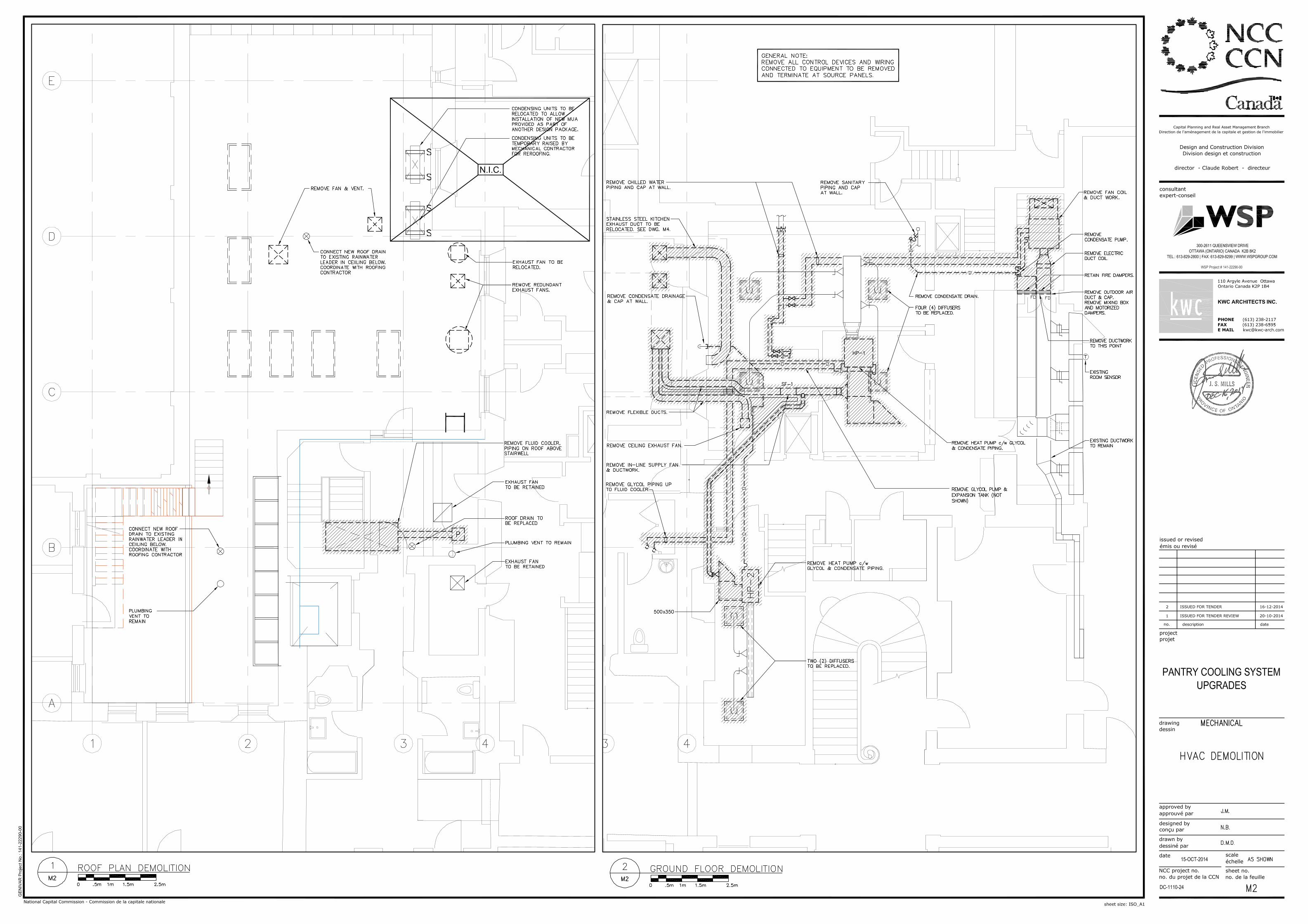
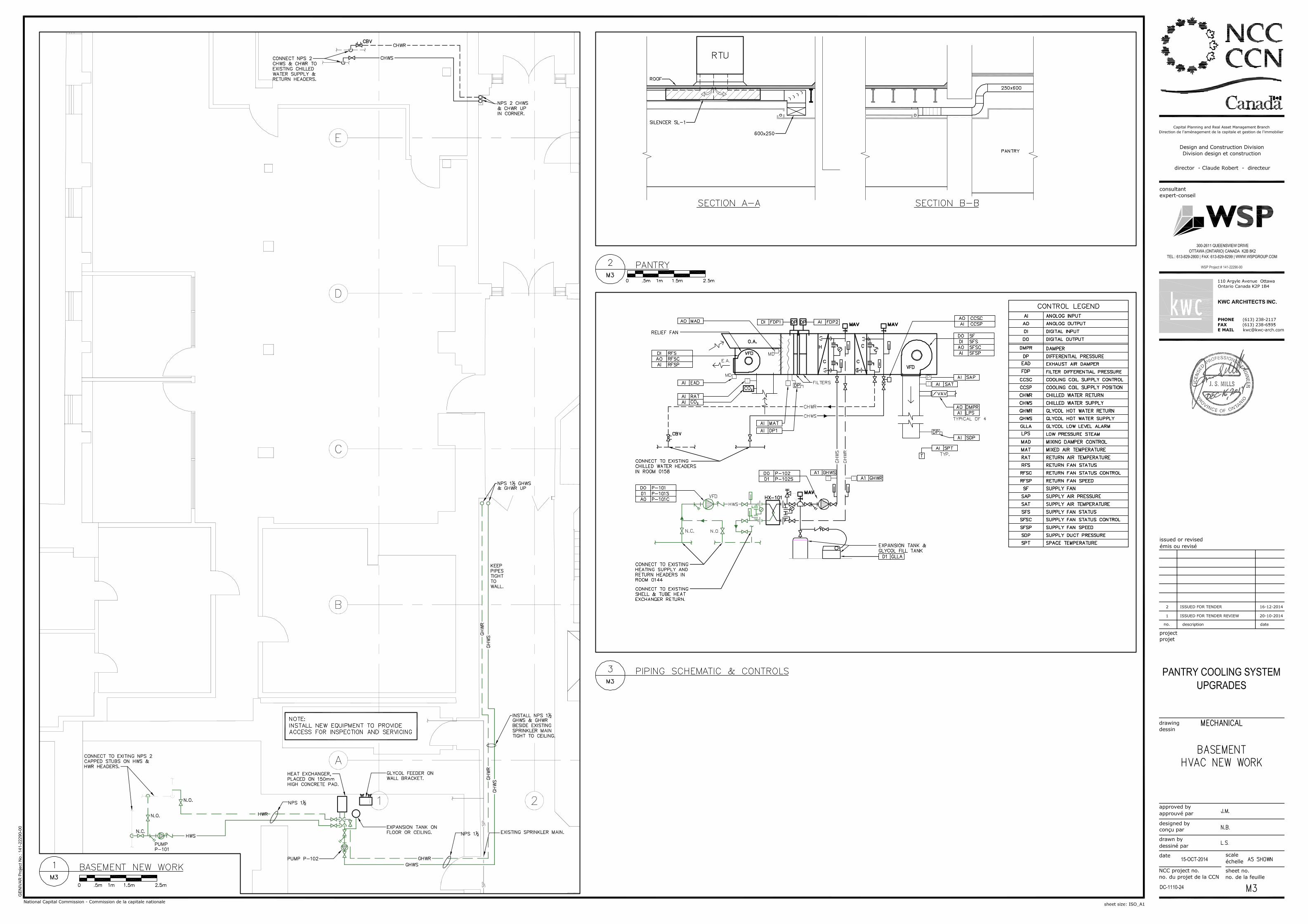
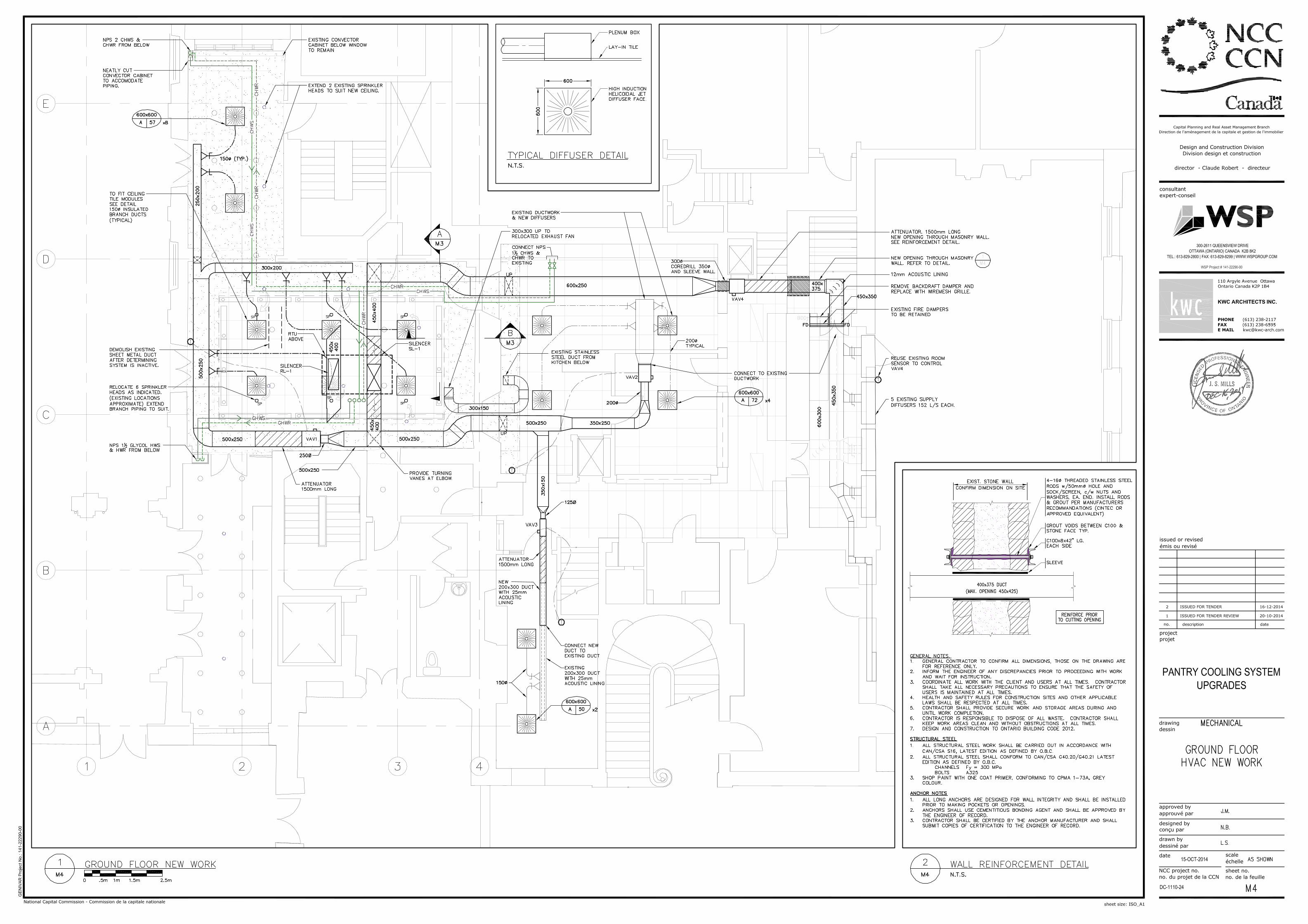
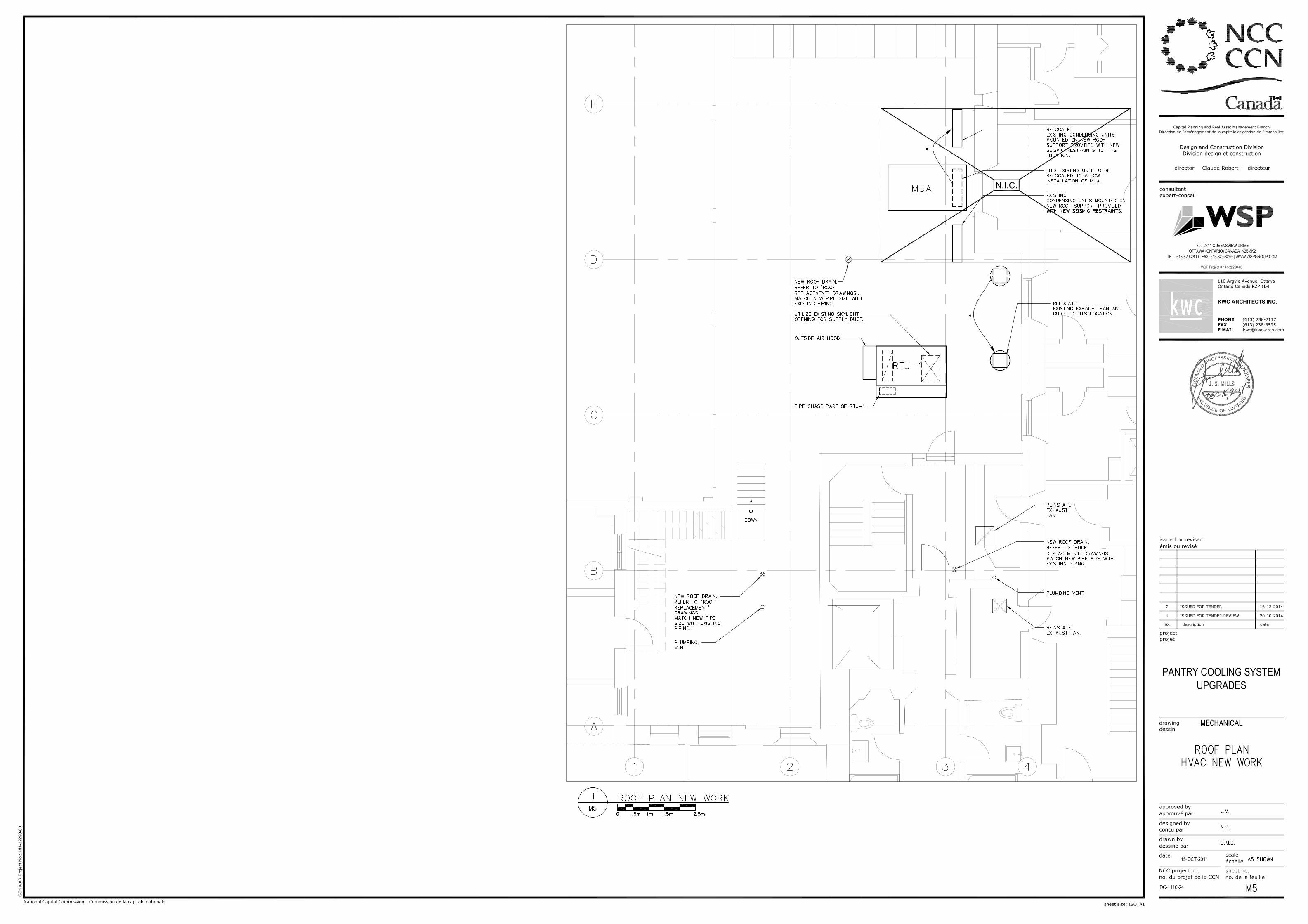
PANTRY COOLING SYSTEMUPGRADES
Key Plan
Plan Rep¯re
consultant
expert-conseil
director - Claude Robert - directeur
Design and Construction Division
Division design et construction
Capital Planning and Real Asset Management Branch
Direction de l'am®nagement de la capitale et gestion de l'immobilier
383 Parkdale Avenue
Ottawa Ontario Canada K1Y 4R4
KWC ARCHITECTS INC.
PHONE (613) 238-2117
FAX (613) 238-6595
E MAIL [email protected]
DEMOLITION-GROUND FLOOR REFLECTED CEILING PLAN
GYPSUM BOARD ASSEMBLIES
MATERIALS;
.1 Gypsum sheathing board: to ASTM C79/C79M, standard 13 mm thick 1200 mm wide x
maximum practical length.
.2 Metal furring runners, hangers, tie wires, inserts, anchors.
.3 Drywall furring channels: 0.5 mm core thickness galvanized steel channels for screw
attachment of gypsum board.
.4 Resilient clips drywall furring : 0.5 mm base steel thickness galvanized steel for resilient
attachment of gypsum board.
.5 Nails: to ASTM C514.
.6 Steel drill screws: to ASTM C1002.
.7 Stud adhesive: to CAN/CGSB_71.25 ASTM C557.
.8 Laminating compound: as recommended by manufacturer, asbestos_free.
.9 Casing beads, corner beads, control joints and edge trim: to ASTM C1047, metal,
zinc_coated by hot_dip process 0.5 mm base thickness, perforated flanges, one piece
length per location.
.10 Joint compound: to ASTM C475, asbestos_free.
.1 Do application and finishing of gypsum board in accordance with ASTM C840 except
where specified otherwise.
.2 Do application of gypsum sheathing in accordance with ASTM C1280.
.3 Erect hangers and runner channels for suspended gypsum board ceilings in
accordance with ASTM C840 except where specified otherwise.
.4 Support light fixtures by providing additional ceiling suspension hangers within 150 mm
of each corner and at maximum 600 mm around perimeter of fixture.
.5 Install work level to tolerance of 1:1200.
.6 Frame with furring channels, perimeter of openings for access panels, light fixtures,
diffusers, grilles.
.7 Furr for gypsum board faced vertical bulkheads within and at termination of ceilings.
INSTALLATION
.1 Erect accessories straight, plumb or level, rigid and at proper plane. Use full length
pieces where practical. Make joints tight, accurately aligned and rigidly secured. Mitre
and fit corners accurately, free from rough edges. Secure at 150 mm on centre.
.2 Install casing beads around perimeter of suspended ceilings.
.3 Install casing beads where gypsum board butts against surfaces having no trim
concealing junction and where indicated. Seal joints with sealant.
.4 Install access doors to electrical and mechanical fixtures specified in respective
sections. Rigidly secure frames to furring or framing systems.
.5 Finish face panel joints and internal angles with joint system consisting of joint
compound, joint tape and taping compound installed according to manufacturer's
directions and feathered out onto panel faces.
.6 Gypsum Board Finish: finish gypsum board walls and ceilings to following levels in
accordance with Association of the Wall and Ceiling Industries (AWCI) International
Recommended Specification on Levels of Gypsum Board Finish:
.1 Levels of finish:
.1 Level 4: Embed tape for joints and interior angles in joint compound and
apply three separate coats of joint compound over joints, angles, fastener
heads and accessories; surfaces smooth and free of tool marks and
ridges.
.7 Finish corner beads, control joints and trim as required with two coats of joint
compound and one coat of taping compound, feathered out onto panel faces.
.8 Fill screw head depressions with joint and taping compounds to bring flush with
adjacent surface of gypsum board so as to be invisible after surface finish is completed.
.9 Sand lightly to remove burred edges and other imperfections. Avoid sanding adjacent
surface of board.
.10 Completed installation to be smooth, level or plumb, free from waves and other defects
and ready for surface finish.
.11 Mix joint compound slightly thinner than for joint taping.
.12 Provide protection that ensures gypsum drywall work will remain without damage or
deterioration at time of substantial completion.
PAINTING
.1 Product Data:
.1 Submit product data and instructions for each paint and coating product to be
used.
.2 Submit two copies of Workplace Hazardous Materials Information System (WHMIS)
Material Safety Data Sheets (MSDS). Indicate VOCs during application.
.3 Submit duplicate 200 x 300 mm sample panels of each paint, specified paint or coating
in colours, gloss/sheen and textures required to MPI Architectural Painting Specification
Manual standards:
.4 Retain reviewed samples on-site to demonstrate acceptable standard of quality for
appropriate on-site surface.
MATERIALS
.1 Paint materials listed in the MPI Approved Products List (APL) are acceptable for use
on this project.
.2 Provide paint materials for paint systems from single manufacturer.
.3 Only qualified products with E2 "Environmentally Friendly" rating are acceptable for use
on this project.
.4 Conform to latest MPI requirements for interior painting work including preparation and
priming.
COLOUR
1. Match existing ceiling and wall colour.
INTERIOR PAINTING SYSTEM
.1 Plaster and gypsum board: ceiling
.1 INT 9.1A - Latex flat finish.
.2 Plaster and gypsum board: gypsum wallboard, drywall, "sheet rock type material", and
textured finishes:
.1 INT 9.2A - Latex gloss level 4 finish (over latex sealer) or match existing gloss
level.
EXECUTION
.1 Compliance: comply with manufacturer's written recommendations or specifications,
including product technical bulletins, handling, storage and installation instructions, and
data sheet.
.2 Perform preparation and operations for interior painting in accordance with MPI
Architectural Painting Specifications Manual except where specified otherwise.
.3 Apply paint materials in accordance with paint manufacturer's written application
instructions.
PREPARATION
.1 Protect existing building surfaces and adjacent structures from paint spatters, markings
and other damage by suitable non_staining covers or masking. If damaged, clean and
restore surfaces as directed by Engineer.
.2 Protect items that are permanently attached such as Fire Labels on doors and frames.
.3 Protect factory finished products and equipment.
.4 Protect building occupants in and about the building.
.5 Surface Preparation:
.1 Remove electrical cover plates, light fixtures, surface hardware on doors, bath
accessories and other surface mounted equipment, fittings and fastenings prior
to undertaking painting operations. Identify and store items in secure location
and re-install after painting is completed.
.6 Move and cover furniture and portable equipment as necessary to carry out painting
operations. Replace as painting operations progress.
.7 Place "WET PAINT" signs in occupied areas as painting operations progress. Signs to
approval of Engineer.
.8 Clean and prepare surfaces in accordance with MPI Architectural Painting Specification
Manual requirements. Refer to MPI Manual in regard to specific requirements and as
follows:
.1 Remove dust, dirt, & other surface debris by vacuuming, wiping with dry, clean
cloths.
.6 Sand and dust between coats as required to provide adequate adhesion for next
coat and to remove defects visible from a distance up to 1000 mm.
.9 Do not apply paint until prepared surfaces have been accepted by
NCC Representative.
APPLICATION
.1 Apply paint in uniform layer using brush and/or roller type suitable for application.
.2 Work paint into cracks, crevices and corners.
.3 Apply coats of paint continuous film of uniform thickness. Repaint thin spots or bare
areas before next coat of paint is applied.
.4 Allow surfaces to dry and properly cure after cleaning and between subsequent coats
for minimum time period as recommended by manufacturer.
.5 Sand and dust between coats to remove visible defects.
TYPICAL CROSS SECTION
ACOUSTICAL SUSPENSION AND ACOUSTICAL PANEL CEILING
DESIGN REQUIREMENTS
.1 Maximum deflection: 1/360th of span to ASTM C635 deflection test.
.2 Fire Performance Characteristics: Identify acoustical ceiling components with
appropriate markings of applicable testing and inspecting organization.
.1 Surface Burning Characteristics: As follows, tested per ASTM E 84 and
complying with ASTM E 1264 for Class A products.
.1 Flame Spread: 25 or less
.2 Smoke Developed: 50 or less
SHOP DRAWINGS
.1 Submit shop drawings of suspension and grid system and ceiling panel material.
.2 Indicate lay_out, insert and hanger spacing and fastening details, splicing method for
main and cross runners, location of access splines change in level details, and
acoustical unit support at ceiling fixture lateral bracing and accessories.
MATERIALS SUSPENSION
.1 Intermediate duty systems to ASTM C635.
.2 Basic materials for suspension system: commercial quality cold rolled steel, hot dipped
galvanized as per ASTM C 635, main beams and cross tees are double-web steel
construction with type exposed flange design. Exposed surfaces chemically cleansed,
capping pre-finished galvanized steel in baked polyester paint - colour white.
.3 Suspension systems: made up as follows:
.1 Profile standard 24 mm wide, total height of tee 38 mm, to ASTM C635 standard
for load compliance, colour to be chosen from standard range.
MATERIAL - CEILING PANEL
.1 Acoustic units for suspended ceiling system, 600x600x22mm;
.1 Type IV, Class A, Flame Spread:25, Smoke Developement:50.
.2 Noise Reduction Coefficient (NCR) designation of 0.80.
.3 Light Reflectance (LR) of 0.89 to ASTM E1477.
.4 Edge Type: Square.
.5 Colour: White
.6 Size: 600x600x22mm.
.2 Acceptable Material: CGC Mars ClimaPlus High NRC and/or approved equal.
INSTALLATION SUSPENSION SYSTEM
.1 Installation: in compliance with ASTM C636 except where specified otherwise.
.2 Install suspension system to manufacturer's instructions and Certification Organizations
tested design requirements.
.4 Do not erect ceiling suspension system until work above ceiling has been inspected by
NCC Representative.
.5 Secure hangers to overhead structure using attachment methods acceptable to
NCC Representative.
.6 Install hangers spaced at maximum 1200 mm centres and within 150 mm from ends of
main tees.
.7 Lay out centre line of ceiling both ways, to provide balanced borders at room perimeter
with border units according to reflected ceiling plan.
.8 Ensure suspension system is co_ordinated with location of related components.
.9 Install wall moulding to provide correct ceiling height.
.10 Completed suspension system to support super_imposed loads, such as lighting
fixtures diffusers grilles and speakers.
.11 Support at light fixtures and diffusers with additional ceiling suspension hangers within
150 mm of each corner and at maximum 600 mm around perimeter of fixture.
.12 Interlock cross member to main runner to provide rigid assembly.
.13 Frame at openings for light fixtures, air diffusers, speakers and at changes in ceiling
heights.
.14 Finished ceiling system to be square with adjoining walls and level within 1:1000.
.15 Maximum deflection shall not exceed 1/360 of the span.
SPECIFICATIONSDRAWING NOTES
DEMOLITION
1205
1202
1204
1204A
GE
NIV
AR
P
roject N
o.: 0167-30-15
consultant
expert-conseil
sheet no.
no. de la feuille
NCC project no.
no. du projet de la CCN
scale
®chelle
date
drawn by
dessin® par
designed by
conu par
approved by
approuv® par
drawing
dessin
project
projet
issued or revised
®mis ou revis®
director - Claude Robert - directeur
Design and Construction Division
Division design et construction
sheet size: ISO_A1
Capital Planning and Real Asset Management Branch
Direction de l'am®nagement de la capitale et gestion de l'immobilier
no.description date
DC 1110-24
National Capital Commission - Commission de la capitale nationale
16-DEC-2014
PANTRY COOLING SYSTEMUPGRADE
Key Plan
Plan Rep¯re
383 Parkdale Avenue
Ottawa Ontario Canada K1Y 4R4
KWC ARCHITECTS INC.
PHONE (613) 238-2117
FAX (613) 238-6595
E MAIL [email protected]
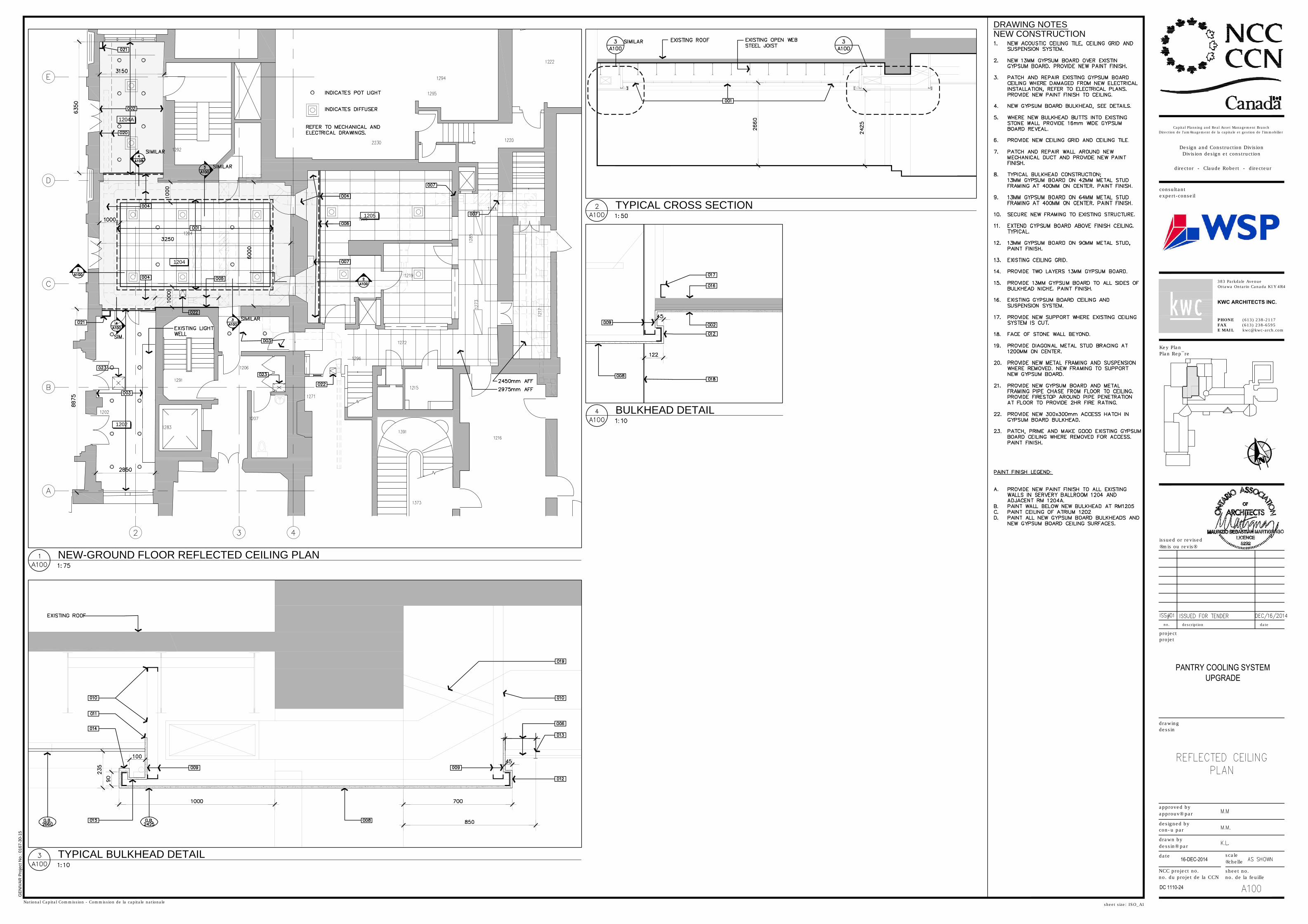
NEW-GROUND FLOOR REFLECTED CEILING PLAN
TYPICAL CROSS SECTION
TYPICAL BULKHEAD DETAIL
BULKHEAD DETAIL
DRAWING NOTES
NEW CONSTRUCTION