Demo Presentation - EICASLAB
16
DEMO TM EICASLAB DEMO EICASLAB The Professional Software Suite f A C lD dF for Automatic Control Design and Forecasting Demo Presentation
Transcript of Demo Presentation - EICASLAB

DEMOTMEICASLAB DEMOEICASLABThe Professional Software Suite
f A C l D d Ffor Automatic Control Design and Forecasting
Demo Presentation

What is EICASLAB DEMO?
EICASLAB DEMO shows you how EICASLAB Suite can help you in all phasesof control design, by presenting a set of test cases (Demo projects) implementingthe most common control algorithm techniques, applied to a “rotating table” singleaxis control application.pp
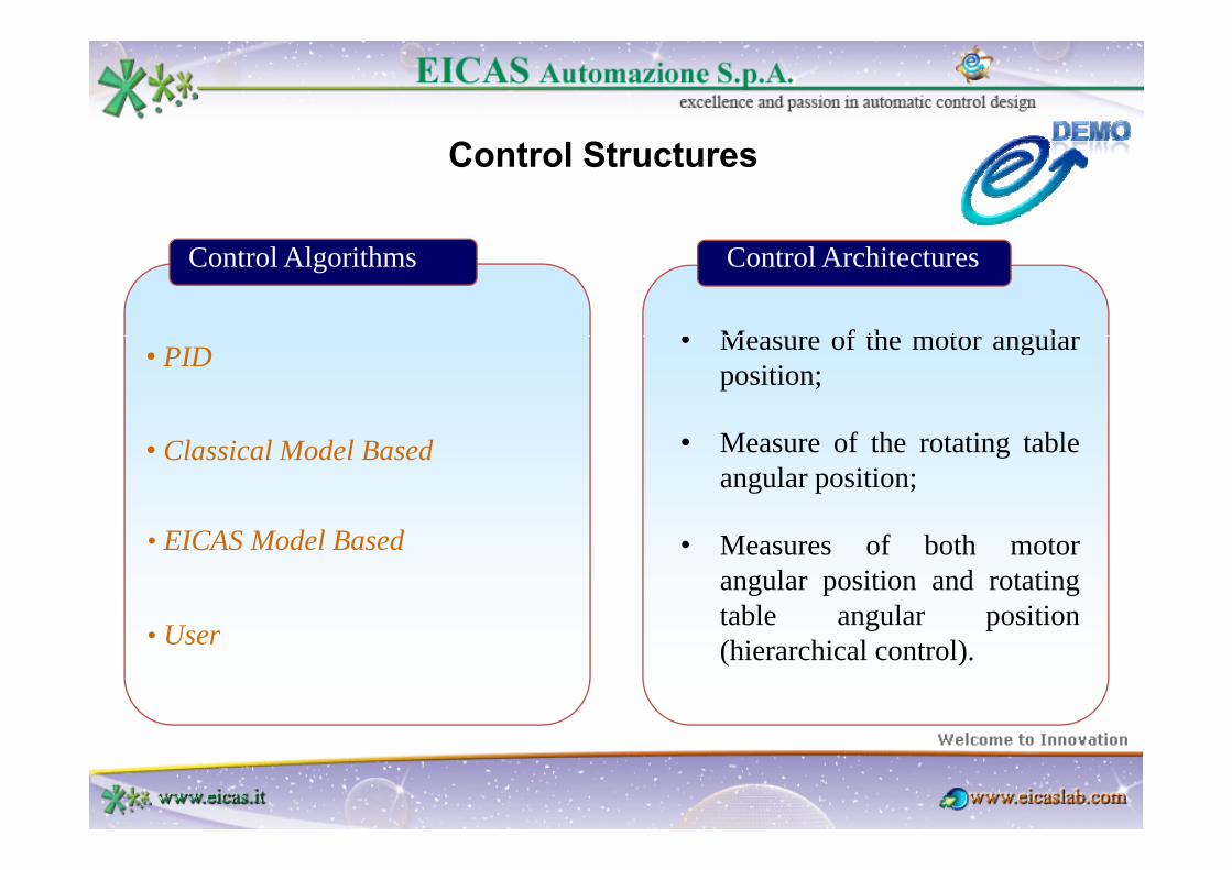
Control Structures
Control Algorithms
• Meas re of the motor ang lar
Control Architectures
• PID • Measure of the motor angularposition;
M f th t ti t bl• Classical Model Based • Measure of the rotating tableangular position;
EICAS M d l B d • Measures of both motorangular position and rotatingtable angular position
• User
• EICAS Model Based
(hierarchical control).• User

Table of contents
• The “rotating table” test caseg
• System requirements
• The Data Sheet Specs of the “rotating table” main components
Th “ i lifi d” d “fi ” d l
• The Control Structures
• The “simplified” and “fine” models
• Performance Analysis

The Test Case: the rotating table control design
E M R G R T
Tm Tt
θem θloadE.M. R.G. R.T.
Electric M t
Reduction Rotating Table
θem
Encoder 1
θload
Encoder 2Motor Gear Table

System Requirements
Motor electric current 12 A
Maximum motor electric current 50 A
Load ang lar rate 1÷1 rad/sLoad angular rate ‐1÷1 rad/s
Load angular acceleration ‐1÷1 rad/s2
Rotation reference bandwidth 4 Hz
Perturbing torque applied to the load:• low frequency (amplitude)• high frequency:
‐100÷100 Nm• high frequency:
a) frequency power spectrumb) r.m.s.
0.5 Hz8 Nm
P iti iPositioning error:• point‐to‐point operating mode• tracking operating mode
1 mrad1 mrad

Operating ModesSe 5
[rad]
POINT-TO-POINT0
2.5
-2.5
[rad]
-50 8 16
time24 32
[s]
Se thdTG
1.8
2[rad]
1.2
TRACKING
0.1
0.6
3 4.5 6 7.5 9
TRACKING
time [s]

Electric Motor Characteristics
L
Data Sheet Parameters
P = 220 W
Jem
RL
T = 0.70 Nm
I = 12 A
ωem
Φ
i
Imax = 50 A
ωmax = 314 rad/sie Φ = 0.059 Nm/A
Jem = 1.5 10-4 Kg m2
ƒ = 0 0003 Nms/radƒvisc = 0.0003 Nms/rad
Tstat = 0.01 Nm

Reduction Gear Characteristics
KrJrg
TData Sheet Parameters
r = 200
Tf
T T 00
Tmax = 114 Nm
Jrg = 1.94 10-4 Kg m2
T T
backlash = ± 0.0025 rad
K = 81870 Nm/radω θ
Coulomb Friction TorqueBacklash and
Hysteresis Cycle

Load Characteristics
Data Sheet ParametersJload
Jload = 5 Kg m2
ωme
E d Ch t i tiEncoders Characteristics
Encoder 1 Data Sheet Parameters Encoder 2 Data Sheet ParametersEncoder 1 Data Sheet Parameters
Quantisation level = 2 mrad
Encoder 2 Data Sheet Parameters
Quantisation level = 0.1 mrad

Plant Simplified Model
Φ 1J θω ,I emT
Reduction ratio r 2J
Electric
Σa+current u
- Σ θ
22
Disturbance
d
22
1
22
JrJTr
JTra s
eq
s
+⋅⋅⋅Φ
=⋅⋅Φ
=

Fine ModelFine ModelΦ 1J
θω , I emTReduction
ratio
Reduction gear
phenomena 2J
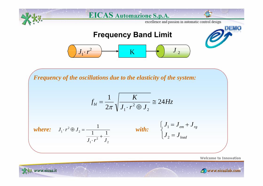
Frequency Band Limit
2J K J1 rJ ⋅ K 2J
Frequency of the oscillations due to the elasticity of the system:
HzJrJ
Kfbl 2421
22
1
≅⊕⋅
=π
where: with: 22
1 111JrJ+
=⊕⋅⎩⎨⎧
=
+= rgem
JJ
JJJ1
22
1 JrJ+
⋅ ⎩ = loadJJ2

Control Structures
Control AlgorithmsControl Architectures
• PID;
• Classical Model Based, based on stateb d t t t l
• Measure of the motor angularposition;
observer and state control;
• EICAS Model Based, based on theEICAS control design methodology
• Measure of the rotating tableangular position;
• Measures of both motorEICAS control design methodology(www.eicas.it);
• Measures of both motorangular position and rotatingtable angular position(hi hi l t l)• User, where the user can develop a (hierarchical control)., p
custom control algorithm.

Positioning error in the “point-to-point” operating mode
Performance Comparison
Control Algorithm Mean squared value (mrad)
Control Architecture
Open loop command
Numerical Optimisation
PID 1.08 Load Measure YES YES
Classical Model Based 2.59 Load Measure YES YES
EICAS Model Based 0.78 Load Measure YES NO
EICAS Model Based 0 37 Hierarchical YES NOEICAS Model Based 0.37 Hierarchical YES NO
Control Algorithm Mean squared Control Open loop Numerical
Tracking error in the “tracking” operating modeControl Algorithm Mean squared
value (mrad)Control
ArchitectureOpen loop command
Numerical Optimisation
PID 1.71 Load Measure YES YES
Cl i l M d l B d 3 82 L d M YES YESClassical Model Based 3.82 Load Measure YES YES
EICAS Model Based 1.18 Load Measure YES NO
EICAS Model Based 0.61 Hierarchical YES NO

EICASLAB DEMO is downloadable from: http://www.eicaslab.com/demo.htm
EICASLAB DEMO is
free of charge!
For info, please contact:[email protected]