DEMO - 1970 Colorized Mustang Wiring and Vacuum … · 1970 Colorized Mustang Wiring and Vacuum...
38
0 Colorized • 1 J .. • .. n .. " OOC" Mustang l" '. :': W I •• &V l IrIng acuum IDiagrams .. • f : • < D .. • '< D , (with Electrical L lustrations) • •• A consolidated collection of original Ford electrical & vacuum diagrams with illustrations Color diagrams for: Automatic Transmission C onvenience System Exterior and Interior Lights Heating and Air Conditioning Horn s and Convertible Top Ignition, Starting and Charging Instrume nt Panel, Tachometer Radio, Stereo and Speakers Windshield Wiper and Wash er Warning Lights and Console Warning Buzzer ... and much more!! All Rights Reserved. Copyright 2008 ForeI PubllshIng Company, LLC , .-".-- .. .•• j .. . --- ..... .. . .-.-.-.- ' -- -- -- -----; :: >or ..... ... ""' .... " ... , .......... , .. .. '''''-'''' -" .... Example of colorized dia g rams "'-_'n '<"", .... ..... -¢<.
Transcript of DEMO - 1970 Colorized Mustang Wiring and Vacuum … · 1970 Colorized Mustang Wiring and Vacuum...

,!~~~~ 0 i~ Colorized
•
1 J ..
• .. n .. " OOC"
Mustang l" '. :':
WI •• &V ~"I l IrIng acuum IDiagrams
.. •
f
: ~J
• < D
..
• '< D
, (with Electrical L lustrations) • ••
A consolidated collection of original Ford electrical & vacuum diagrams with illustrations
Color diagrams for: Automatic Transmission Convenience System Exterior and Interior Lights Heating and Air Conditioning Horns and Convertible Top Ignition, Starting and Charging Instrument Panel, Tachometer Radio, Stereo and Speakers Windshield Wiper and Washer Warning Lights and Console Warning Buzzer
... and much more!!
All Rights Reserved. Copyright 2008 ForeI PubllshIng Company, LLC
, .-".--.. -~. ,~gi~~~, .•• j ... ---....... . .-.-.-.- ' :':~';;'r'" ~ .,,. -- -- -- -----; ::
>or .....
... ""' .... " ... , .......... , .. .. '''''-'''' -" ....
Example of colorized diagrams
"'-_'n '<"", .... ..... -¢<.
Demo Version
This DEMO contains only a few pages of the actual manual/product. Bookmarks work correctly on the full version but not on Demo. Features: - Adobe Reader format - Printable pages - Bookmarked for easy navigation - High Resolution images - Zoom to see exact details - Money back Guarantee

Copyright © 2008, Forel Publishing Company, LLC, Woodbridge, Virginia
All Rights Reserved. No part of this book may be used or reproduced in any manner whatsoeverwithout written permission of Forel Publishing Company, LLC. For information write to Forel
Publishing Company, LLC, 3999 Peregrine Ridge Ct., Woodbridge, VA 22192
1970 Colorized Mustang Wiring and Vacuum Diagrams(Extracted from Form 7098-70-3, Form FD-7795P-70, FP-7635B, and FD-7943-G)
EAN: 978-1-60371-029-9ISBN: 1-60371-029-9
Forel Publishing Company, LLC3999 Peregrine Ridge Ct.Woodbridge, VA 22192
Email address: [email protected]: http://www.ForelPublishing.com
This publication contains material that is reproduced and distributed under a licensefrom Ford Motor Company. No further reproduction or distribution of the Ford MotorCompany material is allowed without the express written permission of Ford Motor
Company.
NNoottee ffrroomm tthhee EEddiittoorrThis product was compiled using several original Ford Motor Company publications. In some cases, there are slightdifferences between publications, so it is important to compare between diagrams, schematics, or illustrations. Thecontents of this product were extracted from: 1970 Car Shop Manual (Form 7098-70-3, September 1969),1965/1972 Ford Car Master Parts and Accessory Catalog (Form FP-7635B, May 1975, and 1970 Wiring Diagrams(Form FD-7795P-70) and How to Read Wiring Diagrams (FD-7943-G).
Disclaimer
Although every effort was made to ensure the accuracy of this book, no representations or warranties of any kind aremade concerning the accuracy, completeness or suitability of the information, either expressed or implied. As aresult, the information contained within this book should be used as general information only. The author and ForelPublishing Company, LLC shall have neither liability nor responsibility to any person or entity with respect to anyloss or damage caused, or alleged to be caused, directly or indirectly by the information contained in this book.Further, the publisher and author are not engaged in rendering legal or other professional services. If legal,mechanical, electrical, or other expert assistance is required, the services of a competent professional should besought.

In the wiring diagrams from the Fordpublication Form 7795P-70F, the MustangExterior Lights Wiring Color Code shows:
297 Yellow-Green
However, in the Wiring Color Codesection of the Mustang Warning Lights ithas:
297 Black-Green
Then, in the Wiring Color Code sectionof the Automatic Transmission, it has:
297 Blue-Green Stripe
ATTENTION
Please Read This
It is important to note that differences exist between similar or like wiring diagrams even thoughthey are original Ford publications. It is for this reason there may be multiple versions of whatappears to be the same wiring diagram. If your vehicle has a color coded wire that does not matcha diagram you should consult the other diagrams contained in the manual for a possible match.
Example of differences
The color coded wiring diagrams are provided forillustration purposes only. Only the wire numbershould be used for the identification of the wireitself. The color coding of the wires in the productmay not match the actual colors of the wires in the vehicle. In some cases, the colors have beenaltered to provide a visual contrast (i.e. the color white has been shaded to make it more visible).As stated in the paragraph above, there are some variation and/or differences between the originalFord wiring diagrams. If your vehicle has a color coded wire that does not match a diagram youshould consult the other diagrams contained in the manual for a possible match.
Disclaimer: Although every effort was made to ensure the accuracy of this book, norepresentations or warranties of any kind are made concerning the accuracy, completeness orsuitability of the information, either expressed or implied. As a result, the information containedwithin this book should be used as general information only. The author and Forel PublishingCompany, LLC shall have neither liability nor responsibility to any person or entity with respect toany loss or damage caused, or alleged to be caused, directly or indirectly by the informationcontained in this book. Further, the publisher and author are not engaged in rendering legal orother professional services. If legal, mechanical, electrical, or other expert assistance is required,the services of a competent professional should be sought.

Number Wire Description Source
2 WHITE-BLUE STRIPE Form 7795P-70F
3 GREEN-WHITE STRIPE Form 7795P-70F
4 WHITE-BLACK STRIPE Form 7795P-70F
5 ORANGE-BLUE STRIPE Form 7795P-70F
8 ORANGE-YELLOW STRIPE Form 7795P-70F
9 GREEN-ORANGE STRIPE Form 7795P-70F
10 GREEN-RED STRIPE Form 7795P-70F
11 GREEN-YELLOW STRIPE Form 7795P-70F
11 BLACK-YELLOW STRIPE Form 7795P-70F
11A BLACK-YELLOW STRIPE FORM 7795P-69
12 GREEN-BLACK STRIPE Form 7795P-70F
13 RED-BLACK STRIPE Form 7795P-70F
14 BLACK Form 7795P-70F
15 RED-YELLOW STRIPE Form 7795P-70F
16 RED-GREEN STRIPE Form 7795P-70F
16 PINK Form 7795P-70F
16A PINK Form 7795P-70F
19 BLUE-RED STRIPE Form 7795P-70F
19A BLUE-RED STRIPE Form 7795P-70F
19B BLUE-RED STRIPE Form 7795P-70F
19C BLUE-RED STRIPE Form 7795P-70F
19D BLUE-RED STRIPE Form 7795P-70F
19E BLUE-RED STRIPE Form 7795P-70F
21 YELLOW Form 7795P-70F
22 BLUE-BLACK STRIPE Form 7795P-70F
25 BLACK-ORANGE STRIPE Form 7795P-70F
26 BLACK-RED STRIPE Form 7795P-70F
26A BLACK-RED STRIPE Form 7795P-70F
28 BLACK Form 7795P-70F
29 YELLOW-WHITE STRIPE Form 7795P-70F
30 BLACK-GREEN STRIPE Form 7795P-70F
30 VIOLET Form 7795P-70F
30A VIOLET (Resistance Wire) Form 7795P-70F
31 WHITE-RED STRIPE Form 7795P-70F
32 RED-BLUE STRIPE Form 7795P-70F
32A RED-BLUE STRIPE Form 7795P-70F
32B Not Listed Form 7795P-70F
34 GREEN-BLACK STRIPE Form 7795P-70F
35 ORANGE Form 7795P-70F
37 BLACK-YELLOW STRIPE Form 7795P-70F
37 GREEN-YELLOW STRIPE Form 7795P-70F
Number Wire Description Source
37A BLACK-YELLOW STRIPE Form 7795P-70F
38 BLACK Form 7795P-70F
38A BLACK Form 7795P-70F
38B BLACK Form 7795P-70F
39 RED-WHITE STRIPE Form 7795P-70F
40 BLUE-WHITE STRIPE Form 7795P-70F
44 BLUE Form 7795P-70F
48 Not Listed Form 7795P-70F
49 WHITE-BLUE STRIPE Form 7795P-70F
50 GREEN-WHITE STRIPE Form 7795P-70F
53A BLACK-BLUE STRIPE Form 7795P-70F
53B BLACK-BLUE STRIPE Form 7795P-70F
53C BLACK-BLUE STRIPE Form 7795P-70F
53D BLACK-BLUE STRIPE Form 7795P-70F
53E BLACK-BLUE STRIPE Form 7795P-70F
53F BLACK-BLUE STRIPE Form 7795P-70F
54 GREEN-YELLOW STRIPE Form 7795P-70F
54A GREEN-YELLOW STRIPE Form 7795P-70F
54B GREEN-YELLOW STRIPE Form 7795P-70F
54C GREEN-YELLOW STRIPE Form 7795P-70F
54D GREEN-YELLOW STRIPE Form 7795P-70F
56 BLUE Form 7795P-70F
57 BLACK Form 7795P-70F
57A BLACK Form 7795P-70F
57B BLACK Form 7795P-70F
57C BLACK Form 7795P-70F
57H BLACK Form 7795P-70F
58 WHITE Form 7795P-70F
63 RED Form 7795P-70F
122 YELLOW Form 7795P-70F
123 RED Form 7795P-70F
137 YELLOW-BLACK STRIPE Form 7795P-70F
140 BLACK-RED STRIPE Form 7795P-70F
140A BLACK-RED STRIPE Form 7795P-70F
152 YELLOW Form 7795P-70F
152 GREEN-BLACK STRIPE Form 7795P-70F
159 Not Listed Form 7795P-70F
161 GREEN Form 7795P-70F
162 GREEN-RED STRIPE Form 7795P-70F
175 BLACK Form 7795P-70F
215 YELLOW-BLACK STRIPE Form 7795P-70F
1970 Color Wiring Codes

Number Wire Description Source
257 YELLOW Form 7795P-70F
262 BROWN Form 7795P-70F
268 RED Form 7795P-70F
269 BLUE Form 7795P-70F
270 BLACK Form 7795P-70F
296 RED Form 7795P-70F
297 BLACK-GREEN STRIPE Form 7795P-70F
297 BLUE-GREEN STRIPE Form 7795P-70F
297 YELLOW-GREEN STRIPE Form 7795P-70F
297A BLACK-GREEN STRIPE Form 7795P-70F
297A BLUE-GREEN STRIPE Form 7795P-70F
348A GREEN Form 7795P-70F
348B GREEN Form 7795P-70F
365 BLUE-RED STRIPE Form 7795P-70F
366 Not Listed Form 7795P-70F
367 GREEN-WHITE STRIPE Form 7795P-70F
383 RED-WHITE STRIPE Form 7795P-70F
450 Not Listed Form 7795P-70F
460 YELLOW Form 7795P-70F
469 GREEN Form 7795P-70F
478 GRAY Form 7795P-70F
482 BLUE-YELLOW STRIPE Form 7795P-70F
482A BLUE-YELLOW STRIPE Form 7795P-70F
490 BLACK-RED STRIPE Form 7795P-70F
511 GREEN Form 7795P-70F
520 VIOLET Form 7795P-70F
627 BLACK-VIOLET STRIPE Form 7795P-70F
640 RED-YELLOW STRIPE Form 7795P-70F
643 YELLOW-BLACK STRIPE Form 7795P-70F
654 YELLOW Form 7795P-70F
655 RED Form 7795P-70F
70 GRAY Form 7795P-70F
708 BLACK Form 7795P-70F
709 BLACK-GREEN STRIPE Form 7795P-70F
763 ORANGE-WHITE STRIPE Form 7795P-70F
806 WHITE Form 7795P-70F
807 ORANGE Form 7795P-70F
904 VIOLET Form 7795P-70F
904 VIOLET (Resistance Wire) Form 7795P-70F
904 GREEN-RED STRIPE Form 7795P-70F
950 WHITE-BLACK STRIPE Form 7795P-70F
Number Wire Description Source
951 GREEN Form 7795P-70F
977 VIOLET Form 7795P-70F
984 BROWN Form 7795P-70F
Note – wire color codes highlighted in REDdesignate a difference either between the originalFord wiring publications or within the samepublication. Those highlighted have the same wirenumber but have different color codes.

Source Document Ford Publication Form 7795P-70
COURSE 13003 and 1703
WIRING and VACUUM
SERVICE TRAINING
FORM 7795P- 70

HOW TO USE THE WIRING DIAGRAMS
THE INDEX PAGE IS THE FIRST PAGE IN EACH SECTION. EACH ELECTRICAL SCHEMATIC WILL HAVE A NOTATION AS TO THE SOURCE OF POWER FOR THAT SYSTEM. ALL W IRES WILL BE SHOWN AS SINGLE LINES TO PROVIDE A CLEAR UNDERSTANDING OF THE DIAGRAMS. TO TRACE A CIRCUIT, IT IS RECOMMENDED TO START AT THE GROUND CIRCUIT OF THE INOPERATIVE COMPONENT, TRACE IT THROUGH ALL CONNECTORS TO THE SOURCE, AND NOTE THE POSSIBLE TROUBLE AREAS AND POINTS OF MOST CON· VENIENT ACCESS. WIRE CONNECTORS WILL BE IDENTIFIED ON THE SCHEMATIC AND THE PICTORIAL DRAWINGS, THIS WILL SHOW THE TECH· NICIAN THE LOCATION OF THE CONNECTORS. MOST WIRE CONNECTORS . .
ARE SHOWN IN OPEN BOOK FASHION. A WIRE ON THE TOP RIGHT OF A CONNECTOR (OPEN SIDE BY SIDE) WILL BE ON THE TOP LEFT SIDE OF THE OTHER HALF OF THE CONNECTOR. SEE FIGURE 1 (WIRE # 140 TO # 140A, ETC.).
WIRE DISCONNECTS AND CONNECTORS WILL ALL BE BLACK UNLESS A COLOR CODE IS NOTED ON THE DIAGRAM. THE COLORED DISCONNECTS AND CONNECTORS ARE TO AID THE TECHNICIAN IN FINDING THE PROPER CIRCUIT TO BE TESTED OR TRACED. THE ELECTRICAL SYMBOLS AND THEIR MEANINGS ARE NOTED ON EACH DIVIDER PAGE TO PROVIDE A CLEARER UNDERSTANDING OF THE DIAGRAMS. PICTORIAL DRAWINGS OF A COM· PONENT WILL INCLUDE THE SPECIFIC LOCATION OF SOME COMPONENTS IN CASES WHERE IT IS DIFFICULT TO DETERMINE IF THE COMPONENT IS UNDER THE INSTRUMENT PANEL OR IN THE ENGINE COMPARTMENT.
RELAYS AND SWITCHES ARE SHOWN IN THE "SYSTEM OFF" POSITION. IF A VEHICLE SPECIFIC WIRE COLOR IN A CONNECTOR DOES NOT MATCH THE DIAGRAM SHOWN, IT CAN USUALLY BE IDENTIFIED BY COMPARING THE OTHER COLORS SHOWN AT THE WIRE CONNECTORS. SPECIFIC WIRE COLOR DEVIATIONS IN THE MANUFACTURING OF A WIRE HARNESS ARE USUALLY FOR A SHORT DURATION.
o ®
I L 14 OA-+6i;-;;®~ 460 e®
®e
r250# I~I:I
Fi gure 1
o oe eo
140
roli}- 250
~

JlIUl. HEATER
6<l CIRCUIT BREAKER
cJ\..O FUSE
--i+-DIODE
--1(--CAPACITOR OR CO~DENSER
-if>-THER MIS TOR
--0 MAINTA INED CONTACT
--" MOMENTARY CONTACT
BUSS BAR
BUSS BAR & SPLICE
o () BUSS BAR
10 01 BUSS BAR
CIRCUIT SYMBOLS
-'Wv-RESISTOR OR
RESISTANCE WIRE
RHEOSTAT (VARIABLE RESISTAt{CE)
...l.. GROUND
....... SPLICE, WELD OR
SOLDER POINT
+ SPLICED WIRES
+ + CROSSOVER WIRE (NO CONNECTION)
-1111111 1f-BATTERY
TRANSISTOR
HORN
SPEAKER
SPARK PLUG
~ JUNCTION BLOCK
DISTRIBUTOR BREAKER POINTS
POTENTIOMETER
SWITCHES
-'-----" ~ PUSH TYPE N.D.
~tto. (SPST)
~
~ PUSH TYPE N,C.
---.. ---,,>'4
(SPOT) CHnER OFF
-o-?n PRESSURE OR VACUUM
OPERATED N.C.
N.O. _ NORMALLY OPEN N.C. - NORMALLY CLOSED
H,C. (SPST)
~ -00-PUSH TYPE ItO. MUl TlPL.E POLE
9~ ROTARY SWITCH
"r ;. N.C.
MERCURY SWITCH
S.P.S.T. - SINGLE POLE. SINGLE THROW D. P.S. T. - DOUBLE POLE, SINGLE THROW S.P.D.T. _ SINGLE POLE , DOUBLE TH ROW D.P.D.T. - DOUBLE POLE, DOUBLE THR OW
HART .~
< : ' , ' ,
" , , ....... - .. ,-' • . . ' ...... --T
\ " , ( i , /' , - ." "" coc.
IGNITION SWITCH
THERMAL SWITCH INTERNAL HEATER H.C.
THERMAL. SWITCH INTERNAL HEATER N.C.
THERMAL SWITCH EXTERNAL HEATER N.C.
/'\70~jo'~ <2-.@. _~Ch [email protected]
TURN SIGNAL SW ITCH
O-E1 9·1·69

N.O. (OPST)
SOLENOID
E II~
N.C. (DPST)
MAP LAMP REL AY
N.O. _ NORMALLY OPEN N.C. _ NORMALLY CLOSED S.P.S.T. _ SINGLE POLE, SINGLE THROW C.P.S.T. - COUBLE POLE, SINGLE THROW S.P.D.T. - SINGLE POLE, DOUBLE THROW D.P.D. T. _ COUBLE POLE, DOUBLE THROW
RELAYS
~ lie
(SPOT)
II~ SOLENOID
IGNITION COIL
COIL AIR CORE
N.O. (SPST)
N.C. (SPST)
DPOl
LAMPS
SINGLE FILAMENT
DOUBLE FILAMENT
CONNECTORS
PLUG NOT USED PLUG
0=: • • • • • • • • • • ~ MALE
r::~ , D D, 'D D: '0 01 ' 0 01 , , ,D 0, , 0 D. ' 0 0' 'T:.'.7t
FEMALE
~ BASIC SERIES
® 0 =~
BULLET CONNECTOR
FEMALE MALE
FEMALE MALE
MOTORS
SPADE HOT USED
~ 1\', --- t---- -~ --~ I--
~ FEMALE SPADE
~AlE CONHECTOR
SPADE CONNECTOR
n®
00 00
MULTIPLE PLUG COVER FOR
CONNECTOR PINS
STARTER 1oI0TDR --<P-PERIUHENl MAGHE· ... SPLIT SERIES
GAUGES
O-E2 9. 1·69
~ICTO."''' "~ . ... tlC
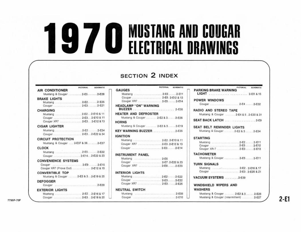
AIR CONDITIONER Mustang & Cougar · 2-E5 .... .. 2-E28
BRAKE LIGHTS Mustang . · 2-E:? .•. . 2-E25 Cougar 2-E3 ••. . 2-E:?!
CHARGING Mustang 2-E2 •. 2-El0& 11
Cougar · 2·E3 ., 2-EIO& 11 Cougar XR7 2-E3 . · 2-E12 &. 13
CIGAR LIGHTER MuSllng .. 2-E2 . .. 2-E34
Cougar 2-E3 · 2-E22 &. 34
CIRCUIT PROTECTION Mustang &. COugar 2-E37 a. 38 .. ' ... 2-E37
CLOCK Mustang 2·E5 ...... 2-E22 Cougar 2-EI4 .. 2-E22 &. 23
CONVENIENCE SYSTEMS Cougar 2·E9 _,_ .. 2-EIS Cougar XR7 (Prove Out) . . ....... 2-E!2 &. 15
CONVERTIBLE TOP Mustang &. Cougar . ... 2-E2&3 . . 2·E19&25
DEFOGGER Cougar ......... 2-EZ9
EXTERIOR LIGHTS Mustang ... 2-E2 . . 2·EI6& 17 Cougar . • .•• 2-E3 · 2-EtS &. 20
779SP-70F
MUSTANG AND COUGAR ELECTRICAL DRAWINGS
SECTION 2 INDEX
GAUGES Mustang ...........•.•....• 2-E5 ..... 2-Et l COligar .............. 2-E5 . 2'Et2 & 13 Cougar XA7 .. ." •....... 2-E5 ..... 2·E14
HEADLAMP " ON " WARNING BUZZER .. . . . . . . . . , ......... 2-E36
HEATER AND DEFROSTER MlIltlng & Couglr
HORNS Mliitang & COllgar
KEY WARNING BUZZER
IGNITION MUllang Collgar XA7
Cougar
INSTRUMENT PANEL Muatang Cougar Cougar XA7
INTERIOR LIGHTS Mustang . Cougar .. Cougar XA7
NEUTRAL SWITCH Mustang Cougar
2·E2&3 . 2-E28
2-E2 & 3 ..... 2-Et9
.2-E35
2-E2 . 2-EIO& II ... 2-E3 . 2-E12 & 13
2·E3 .... 2-E14
2-E6 2-E7 · 2-E22 & 23
. 2-E8 ..... 2·E23
. • 2·E2 · .. , · 2·E22 2-E3 .. . .. 2-E22
• 2-E3 .... 2-E25
•. 2-E33 2-EIO
~ICTO~IA~ IC~' MATIC
PARKING BRAKE WARN ING LIGHT ........... 2-E9 & t5
POWER WINDOWS Cougar 2-E4 .•.•. 2-E32
RADIO AND STEREO TAPE Mustang & Cougar 2·E4 & 5 , 2-E30 & 3t
SEAT BACK LATCH ... . •.....•...• 2-E9
SEAT BELT REMINDER LIGHTS 2·E2 & 3 . .. 2-E34
STARTING MUltang Cougar Cougar XA-7
TACHOMETER Mustang & Cougar
TURN SIGNALS Mustang Cougar
2-E2 .. 2-EII 2-E3 2-E12 2-E3 •••• . 2-EI3
2-ES .... 2·EII
2-E2 . 2-Et6 & 17 . 2-E3 2·E20 & 2t
VACUUM SySTEMS ..... , .. 2-E39
WINDSHIELD WIPERS AND WASHERS
Mustang & Cougar .. 2·E2 & 3 ..... 2-E26 Mustang & Cougar ('nlermittenl) . 2·E27 2-E1

.. · .... , ... . TUO' , ...... ...... .
, •
'no
:::::::-------
I..' .•• .,UIoO'
,-
,"0, WI.", ''''.
'Ulvt "'. I""'''' ... ~O.IU .,.. UC. ul • • n &1.1
1970 MUSTANG OVERALL VIEW 2-E2
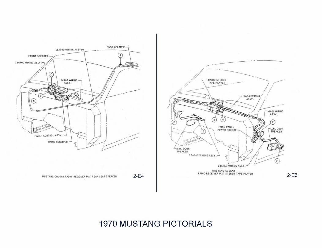
18 ... 900 WIRING "'SSY. ---
R SE ... T SP(.lXER MIJST .... ~ C-COUC ... R RAOIO RECEIVER 000 RE'"
1970
2-E4
-/' ~- ------------; :Y AAOIO S TEREO ___ ) ~
/: "" 'L"" . / ~ . .
~~~.~- ~-----::'''~:~:'''// - -----:; ;-;;:;rIUO I "WI::NG
"'SSY.
r.;-----_____ _.' \ E
W "''''''' {A·:-~~ (r"""""u: Ji J' ,Lf'-~ :_ ..-:-
A.H. OOO R • ." SPEA KER "
1'''''b9 WIR1NG ASSY . ..:
L- .. -13A7&9 WlR1NG "'SSV.
MIJSI"' N~1~~~~~ T"'PE PLAV£R R"'DIO RECEIVEA (,1,1,
MUSTANG PICTORIALS
2-E5

, ,
BI.OWU RUISTO~ -li , , ,
UC><OU£I(~
I"~I "'~IOC '.ny.
>7-::=J { _ -----
ICl'lno. COIL
i-. I ...... ,
-r----------______ ~~y CLOCK ASSV.
/~ ..... pLl/..p
) .'
/ ,
~ f USE ~AIIE L
IUO I WIRIIiG ASSY .
MUS rA NG-COUCMt CLOC ~·"'API..A}.''' CI RCUITS
"U jl~", ·rouCAA IACHO .. E!E" OOWI "IIOtl~ 6~A. C' .6 >
1970 MUSTANG PICTORIALS
,
J , ,,
2-E5

Q . 1'"IW.. ~_.
Q -1370'1- l.1li' _. (L ',) .~ <..- _. (I..a.)
= . f >JOl~ . 1(>. q .-. vu.ou-.. __ ,_. om.u 6) • '16,
- nlSO- ' Wl!a .sST. ( """'!II;T ......-oo )
-0)"'" ~-. ( ....... I lGULl
~ f;, . 111'" ~
-110.<099- AIJ:Ul
~ . \ )766,.,. ... CU.
>oj 3&lm-s cw
i~l ." JAIII Ir""'" ,sW/'" cw 0 · """,, )
in -1).1»- Il.I!!tU Asn. \.'0 .- SSW1-sJ6 sc_ (J .Jti>.II . )
© \" ,e".n ... cu, .- 00921 ... 2 SO""', (2_~. )
(n ." lIMOS \/IIIIJI:I .so."
Q " )6J01"'~ ..,'"
" -~~ ~ I IoO¢!. ...... "" NIl PIJIEL
to >III COIIIl. ~IOICS .
to III:tttlt IW<'n SIma
TO IIP.TPI I\!SIMQ~
1'0 ""'.""'" S.tm:ll ,
TO \IlPCII S1ItTCI • Clc;o." UGIII'&A
TO 1Gn'!!..- . 1200 an. =,-TO Il1010 """"IVU,
._" '''''318 llISY . 1'1) CJ.C<:l • ....,,.,... , TQ 131712 ASS •.
!ICS'!'RJHI:It' CWSTIlt
TO 'fCfI<O SII~
"",00 CO<Pr . VIIIIlIO ,
.Il"" ~
JS1~1 on ..... !I\Ia =t . MOJI rm.L SUI'I'OII7
.1.\1.726 ........ _Y . (loSII lOEC")
~""'71'" """"'. 1Ji£ TIIRi:II ( .15 • 6.(0) PncIS ",.".. . Ie IS IOcr snc~
TO GIllIa WD'S m l(>6-S16 sc_
!'<II\n.<nIO ~ 1.""1',
11\lC7-a)6 !CN''' (~..,."..,.)
1970 MUSTANG INSTRUMENT PANEL 2-E6 9-1-69

TlU",,' ............. ......... , .. ----., •.. [email protected] ~ •.
lOOn, ~~ •••. ~.
16 ... •
......... --
-,.-.. :~ '.-::: ' - '
.. ..,
·" .....
·' •• 1»· +--70' ...... ''''.
"
... .: . .. n -.-...• ~
(~-:";;";~·"~· ~~~'-;'~~lw~~~~~I~~~I~f~~~~ .11 . ...
"
~~~n'.
•
It ;]11 ~-... _(\.01<0 • .. 1 ... , 1.O,,_.U •. r..,.,
.( ......... , ..... , --"' . • .. . ... f
":'I~~~f3© I
., .....
\ .ntl ,,,y. '
., ......... . .
.h .• • • " • .
•••
.. .......... ,rooo'
...... « , .... " .. )
....... ..... """"'1 ", ... , ' '' '''
.......r... .to =<B1*= .. IIO, __ "'L_". __________ .::==~ .. ... , ... ,.001 '._ ....... _.JO¢ "' .... ", •• _ .. , ..... ..
:~1:' ...... " .. .. M • ....... . Y( ....... " .... "''':C",,,,,_ ~~:''' ''''''' I'''''' ..... "' ......... ..... -" .. -... IO"U "0.
1970 MUSTANG CONVENIENCE SYSTEM 2-E9 9-1-69

'1'014· 'u" "' .....
'"' ______ ~~:::n ... 11 , rro a~· ""11 : f '"'"
II AI: '
., w"
'--------i~---=::-J "''''''' .
.... n · ~"t1Hh
).0 11 ~j b I I S,,··· .. nv· r 4 · @
....... £0 "''''OO.,X ... ,.~
,".E .. O"'E ..... " ,p[CIF,(O ••• CO"(C'OU AI:( I ... "
• ",lCt .-o ~u .un, . a ' Clll> AS __ 'IOtA'( CO_U'O,S .... __ ,e ..... -,
" '" n. '" .. lOl>
"""'~
VI •• "'" ",~ "'. •• uE • ... c. I<.>(.""(U <0.[["
,9" I~
. AI: . 01' .. <1' .....
.,'"IU "[sp,,, ... n ,..;, .... co""", .. ".
I I ''''''''''''[11 1'0.11 ... . ~ .. . ,,, , . , ,
Uf" 1.-'''''''01
." Y_UI.ofll[...,'[ ,"CIFI(O Oll CO.>;f.croo, .. ( I<.>(~
• s' uee ~ C'O<I""
0 .'" '.U 'E*SClOCU:I" __ '''''''' ' _ ",eTO", _ All( ""_tA •• ~_
1970 MUSTANG AND COUGAR HEATER AND AIR CONDITIONING
· ... n·
,t .. ,,". Sw"ao
.H't. ll.OWI:' "'''a-11111
~ .. "
I I '0. . . : . .0"'''''''' I tr:. '-0 ...... o .'
" '" , .. , .. '" ,.,.
>1 ....... .. "" ... 'w, I ... C. • ... c.".!!.
2-E28

Source Document Ford Publication Form 7795P-70
COURSE 13003 and 1703
WIRING and VACUUM
SERVICE TRAINING
FORM 7795P- 70

HOW TO USE THE VACUUM DIAGRAMS
IF IT IS A FORD CAR LINE VACUUM SYSTEM, THE TECHNICIAN WILL FIND A PAGE FOR THE TOTAL SCHEMATIC SYSTEM AS WELL AS A LISTING FOR A SCHEMATIC AND PICTORIAL OF EACH SUBSYSTEM ON EACH SECTION INDEX PAGE. IT IS RECOMMENDED THAT THE TECHNICIAN FIRST TURN TO THE TOTAL SYSTEMS SCHEMATIC TO DETERMINE IF THERE ARE ANY BRANCH SYSTEMS OPERATING FROM THE SAME SOURCE. THIS WILL ASSIST IN LOCATING SYSTEM TROUBLES. HE WILL THEN BE ABLE TO TURN TO A PAGE TO FIND DETAILED INFORMATION
ON A PARTICULAR SYSTEM. IN TRACING VACUUM SYSTEMS, IT IS RECOMMENDED THAT A CIRCUIT BE TRACED FROM ITS CONTROL UNIT TO ITS SOURCE OF VACUUM, AND THEN FROM THE CONTROL UNIT TO THE OPERATING UNIT, NOTING POINTS OF POSSIBLE MALFUNCTION AND ACCESSIBILITY.
THE VACUUM SYMBOLS AND THEIR MEANINGS ARE NOTED ON EACH DIVIDER PAGE TO PROVIDE A CLEAR UNDERSTANDING OF THE DIAGRAMS.
Q
4 ~
1F
9l= {]
+ 0
VACUUM CIRCUIT SYMBOLS
VACUUM MO TOR OR RESERVOIR
INTAKE MAN IFOLD FITT ING
VACUUM CONTRO L
Q OR DUAL VACUU M MO TOR
TEE CONNECTOR
4 - WAY TEE CONNECTOR
VACUUM DISTRIBUTOR
OR ~ VACUUM LIN E CROSSOVER
CONNECTOR
~ RESERVOIR AND U CHECK VA LVE
U NIPPLE ON A MO TOR
T OR 0 CAP (NO T OPEN)
~,~ §) GROUP CONNECTOR
~ HOSE CLAMP
-- ~ --DASH PANEL GROMMET
o CHECK VALVE

P.usEMGU COMPARTIOEIH
00 WT5IOE R~CIRC. - • WHITE
•
IRf5T'£TORI ... I' AIR OOOfl I
I'UIIPLE
o HEHER
..... TER VALVE
_PlE
'I
It05E ilZE . ,. C I/~
, M
SWITOl
, L.f.c
~ ..... "
,
BLACK
, iJ:,
:9,
l .o.UTO. , ...
ORANGE
WHITE
• • •
• •
,
,
CHECK ~"'LVE
POWER! I IlRAXE 1I0000TH
, ,
WHIT(
WlllTE
~~ ...... ~""~ , .... GREEH .OP£M :e
' -- , BY· p.us VALVE ----l
(HCllU'A.L P0511~) -:---1 'I'- '
~~-----=~~------~ lEl.lOW· CLOSE
1970 MUSTANG AND COUGAR TOTAL VACUUM SCHEMATIC
YH.lOl
i$1 ~-
WHITE
J
Vacuum Diagrams
Note
Color Vacuum Diagrams included


"I .. IDIIITIfICA'QIII • • . • • • . • • •• ,. nau ..... . . . .. . . . . . . 11
. Il • IJ
•• DUTlFICA_...... .. ... . 11 . 22
11011 ... 100mFICAnOil . . • • • • . . • • . . • .. IEAII .. •. . • .• • • •••• . •.• ••..• .. •..• 41 __ .......... ",R • . . .. .. . .. 4Z _ ... HDDDI, ...... E
DOD'" r ••• lAm • • a
neFPMlL •••• COYER. IIOOD eMIl
TlWllFEI. vrlYL IIOOFS. , ... , .•. .. maRlOIl TRIM .. . . . . . ... ..... ... ... ., lID' "ELL. EXTERIOR ~
FMIIES. UfII.OERIODY • • • • • • • • • • • • • ..
IIHI ... ID(lnFICATIOI . . • . . •. .. PRUtlUVEIlY •• II IIAIIITEIIMCE • . • II
in ... 'CE ...... .. · Q
... .. .. . ........... .. SERVICE PUBLICATIONS
GROUP INDEX I NDEX and IDENTIFICATION
CHARGING SYSTEM
EXTERIOR LI GHTS, HEADLIGHT DIMMER,
TURN SIGNALS, HORNS
INTERIOR LIGHTS, INSTRUMENTS, INSTRUMENT PANEL CONTROLS and CLOCK,
VENTILATING, HEATING, AIR CONDITIONING
AUXILIARY EQUIPMENT: RADIO, STEREO,
WINDSHIELD WIPER and WASHER, LIGHTERS, ASH
RECEPTACLES, MIRRORS, ETC.
WIRING, CIRCUIT PROTECTION, BULB CHARTS
VACUUM SYSTEMS
SPEED CONTROL, ANTI-SKID CONTROL
F IRST PRINTING - SEPTEMBER'. 1969
@ 1969 FORO MOTOR COMPANY. DEARBORN, MICHIGAN

FOREWORD
ThiJ manual iJ divided into five volumes: 1 - Chassis, 2 - Engine, 3 - ElectriCllI, 4 - Body, 5 - MainteTUl1lce and Lubrication. These volumes should provide Service Technicians with complete information covering normal service repairs on all 19 70 model passenger cars built by Ford Motor Company in the U.S. and Canada. As changes in the product occur, this information will be updated by Technical Service Bulletins. When issued, 1'$B information always supersedes that published here.
Within each volume, information iJ grouped by system or component plus "General Service" parts which contain information which iJ common to several similar.components.
The table of contents on the first page of elJCh volume indicates the general content of the book and provides a handy tab locater to make it easy to find the first page-of each ''group.'' That page wiU contain an index to "parts" and the first page of each "ptl11" contains a detailed index which gives page location for each service operation covered. Page numbers are consecutive in each "part. "
Those who have previously used Ford Shop Manuals will find a major change this yelll' in the division of information into "groups" and "parts. " To make teference f!IISier, information has been broken down into smaller units so that essentially there iJ now one ''part'' for each component or system. Group numbers have been c1urnged so tMt the first digit of the number indicates the volume in which the group may be found.
Example:
36 - 05 - 13 Volume 3 - Group 6 - Part 5 - Page 13
We hope tMt this c1urnge in indexing will make it easier and quicker to locate desiTed information within these manuals.
The descriptions and specifications in this manUQ/ were in effect at the time this manual was approved for printing Ford Motor Company reserves the right to diJcontinue models at any time, or cMnge speCifications or design, without notice and without incurring obligation.
~~ SERVICE PUBLICATIONS

30-01-01
Identification
w 1002·8
MANUFACTURED BY FORD MOTOR COMPANY
100001
09/69 THIS VEHIC LE CON fORMS
TO ALL APPLICA BLE FE DE RAL
MOTOR VE HI CLE SAfETY STAN
DARDS IN EFFECT ON DATE Of
WI LL V,",I!T .... ITH VEHICLE LINE
l--+==MANUFACTURE SHOWN ABOVE .
5
MADE IN u.s .....
G) CONSEC'.'TIVE UN;T NO
CD 1l00T SUhA l CODE
o MCVEL HAil (OOE
o ,l, SS EMBL ~ <'LA NT coo£
o ENGINE COOt
CD TRIM (OOf
OffiCIAL VEH ICLE IDENTIFICATIO N NUMBE R
The official Vehicle Identification Number (VIN) for ti tle and registration purposes is stamped on an aluminum tab thaI is riveted 10 Inc instrument pancl close to the windsllield on Ihe driver's side of the tar and is visible from outside (Fig. I).
CD !IUd? .>,XlE (DOE
o (OLOil CODE
o SOOT HPt: Coo{
® O:STRICT SPEC EQUIP CODE
® TII ANSMI SS:ON CODE
w 100'1 ...
VEHICLE CE RTIFICATION LABEL
The Vehicle Certification Label (V ,C. Label) is attached to the rear fa ce of the driver' s door. The upper half of the label contains the name of the manufacturer, the month and year of manufacture and the certification statement. The V.C. label also contains the Vehicle Identificalion Number. This number is also used lor
30-01-01
GROUP
30 Warranty identificatioo of the vehicle. The first number indicates the model year. The leiter following the model year number indicates the manufacturing assembly plant, The next Iwo numbers designate the Body Serial Code followed by a leiter expressiog the Engine Code. The last six digits of the Vehicle Idelllification Num· ber indicale the Consecutive Unil Number.
The remaioing information on the V.C. Label consists of pertineot vehicle idenlification codes. The BODY code is IWO numerals and a letter identifying the body Style. The COL (color) code is a number or letter (or both) indicating the exterior paint color code. The TR IM code con· sists . of a number·letter combination des· ignlling the io terior trim. The Axle code is a number or leiter indicatinS the rear axle ratio and standard or locking type axles. The TRNS. code is a number or letter indicating the type of transmission, numerals for manual and leiterS for auto· matic or semi·automatic. The DSO code consining 01 two numbers designates the distriCt in which the car wu ordered and may appear in conjunction with a Dom· estic Special Order or Foreign S~cial Order number when applicable. Ford 01 Canada DSO codes consist of a letter and a number except for export codes which are designated by two numbers.
MODEL YEAR CO DE
The number 0 designates 1970.
ASSEMBLY PLANT CODES
c ... Letler
A ...•••••.•..••••••..•••• B ..•••........... C ....................... . o E f .................... .. G ............ . H .• I ................. . II ..................... .. l ...................... . N ....................... . P ........................ . R .......... . S .... ... ................ .. T ....................... .. U .• V ........ .. W ....................... . X ........................ . y ........................ . Z ........ ..
Atlanta Oabille (Canida) Ontario t ruck Dall as Mahwah Dearborn Chicago lo ra in Los Angtles KanSlrs City Michie.n truck Norfolk Twin Ci ties San JoSt Allen Park Metuchen louisyille lIenhlcky Truck Wayne SI. Thomas Wixom St.louis
C1I24Ss.A
Vol. 3 Electrical
Note
Included in this product is the entire Volume III Electrical of the 1970 Car Shop Manual.

30-01-02
DATE CODES A number signifying the date preceeds
the month code letter. A second-year code letter will be used if the model exceeds 12 months.
Month Code First Year
Code Second Year
January ................. . A.................... N February ............... . March ................... . April ..................... . May ...................... . June ..................... ..
B .................... P C .................... Q
R 0 .................. . E .................... S F .................... T
July ...................... .. August .................. . September ........... .. October ................ .
G .................... U H ................... V J .................... W K .................... X
November ............ .. l .................... Y December ............ .. M ................... Z
DISTRICT CODES (DSO) Units built on a Domestic Special Or
der, Foreign Special Order, or other Spe· cial orders will have the completc order .number in this space. Also to appear in this space is the two-digit code number of the District which ordered the unit. If the unit is a regular production unit, only the District code number will appear.
CONSECUTIVE UNIT NUMBER Starting Serial Numbers-1970 Passenger Cars 100,001 - Ford, Fairlane, Falcon, Mustang, Thunderbird, Maverick 500,001 - Mercury. Meteor, Montego. Cougar 800,001 - Lincoln Continental & Mark III
RADIO IDENTI FICATION SAMPLE NUMBER
DODA 1 -.
Year Car line
MANUFACTURER CODE NUMBER
1
125 Bendix 185 Motorola 260 Philco
BASIC NUMBER AND TYPE RADIO 18806 AM RadiO 1911241 AM/FM Multiplex 1911242 AM Radio/Stereo Tape Player 1911243 AM-Oual Channel Stereo 1911244 AM Signal Seeking Radio 1911237 Stereo Tape Player Deck
Identification
FORD
Code District
11...................... Boston 13...................... New York 15...................... Newark 16...................... Philadelphia 17...................... Washington 21 ....................... Atlanta 22...................... Charlotte 24...................... Jacksonville 25...................... Richmond 28...................... louisville 32...................... Cleveland 33 ........ ;;............ Detroit 35...................... lansing 37...................... Buffalo 38...................... Pittsburgh 41 ................. h... Chicago 43...................... Milwaukee 44...................... Twin Cities 46...................... Indianapolis 47...................... Cincinnati 51...................... Denver 53...................... Kansas City 54...................... Omaha 55...................... St.louis 56...................... Davenport 61...................... Dallas 62...................... Houston 63...................... Memphis 64...................... New Orleans 65...................... Oklahoma City 71 ...................... los Angeles 72 ...................... San Jose 73...................... Salt lake City 74...................... Seattle 75...................... Phoenix 83...................... Government 84...................... Home Office Reserve 85...................... American Red Cross 89...................... Transportation Services 90·99................. Export
18806 t
Type
B t
Design level
LlNCOlN·MERCURY
Code District
11....................... Boston 15...................... New York 16...................... Philadelphia 17 ...................... Washington 21...................... Altanta 22...................... Dallas 23...................... Jacksonville 26...................... Memphis 31...................... Buffalo 32...................... Cincinnati 33..................... Cleveland 34...................... Detroit 41 ...................... Chicago 42...................... St.louis 46...................... Twin Cities 51....................... Denver 52 ...... ~............... los Angeles 53....................... Oakland 54...................... Seattle
30-01-02
84 ......................Home Office Reserve 90...................... Export
FORD OF CANADA
Code District
Bl ..................... Central B2...................... Eastern B3....................... Atlantic II th ru I7 .......... Export B4 ................. ;.... Midwestern B6...................... Western B7...................... Pacific
Note: Canadian lincoln·Mercury units use prefix "A" in place of "B"
260 t
Manuf act ur'er
o 11 ~ -.
Year Week
IDENTIFICATION NUMBER Number Car Line ~ C9M Ford and Meteor C9ZA Mustang and Cougar DOM For d and Meteor DODA Maverick DOGA Cougar DOlA Continental Mark III DOMA Mercury DOOA Fairlane and Montego DOSA Thunderbird DOVA lincoln Continental DOWA Cougar DOYA Meteor DOZA Mustang
CK2456·A

31-01 -0 1 31-01 -01
GROUP
stem 31 PAGE PAGE
PART 31 -01 PART 31 -04 General Charging System Service ...... 31 ~O 1-01 leece·Nevi lle Alternators ........... ....... 31 -04-01
PART 31 -02 PART 31 -05 Autolite Alternators ....................... .... 31 -02-01 leece-Nevi lle Alternator Regulators .. 31-05-01
PART 31 -06 PART 31 -03 Autolite Alternator Regulators ...... .... . 31-03-01 Batteries ....... ........................ ... ........ .. 31 -06-01
PART 31-01 General Charging System Service
The alternator and alternator regulator are precision built un its, and the equipment to make tests in the charging system must be accurate . Volt· meters must be accurate with in 0,1 (one tenth) volt within the range or 12 to 16 volts and am meters within one ampere at 30 to 65 amperes to permit correct measurement of the alternator and regulator. The meters on Rotunda equipment should be calibrated once a year and the date of calibration stamped on the meter face . 11 is recommended that this practice be fo llowed by technicia ns with other than approved equ ipment in order to maintain their meters at acceptable accuracy.
Certain tests out lined in this section are illustrated in schematic and in
pictoria l form . The schematic illustra tes the internal connections of the Rotunda equipment so that these connections can be duplicated when this equipment is not avai lable. The Rotunda test units are a combinati on of accepted instruments incorporated into a si ngle unit. The various circuits involved in the tests can be se lected by means of switches without the necessity of changing connections. As a result. the time required to test units and circuits on the vehicle is reduced.
Where applicable. the tests a re divided in to On The Vehicle and On The Test Bench procedures. Either procedure ca n be followed depending on the equipment available for the tests.
Trouble shooting or diagnosis is re-
quired before actual repairs are made in the electrical system . Even where an obvious fau lt makes the replacement of a unit necessary. you must still find out why the unit fai led. The trouble Shooting proced ures given in th e Electrical System s Di agnosis Manual will aid you in mak ing a correct diagnosis. When a trouble is diagnosed correctl y. unnecessary repairs a re prevented . the time the vehicle is out of service will be decreased. and the repai rs that are made will be permanent .
Schematic wiring diagrams (Figs. 1.2 and 3 Parts 31-02 a nd 03) of the chargi ne circuits show the internal connections and windings of the various uni ts. Color codes are shown to aid in tracing the circuit.
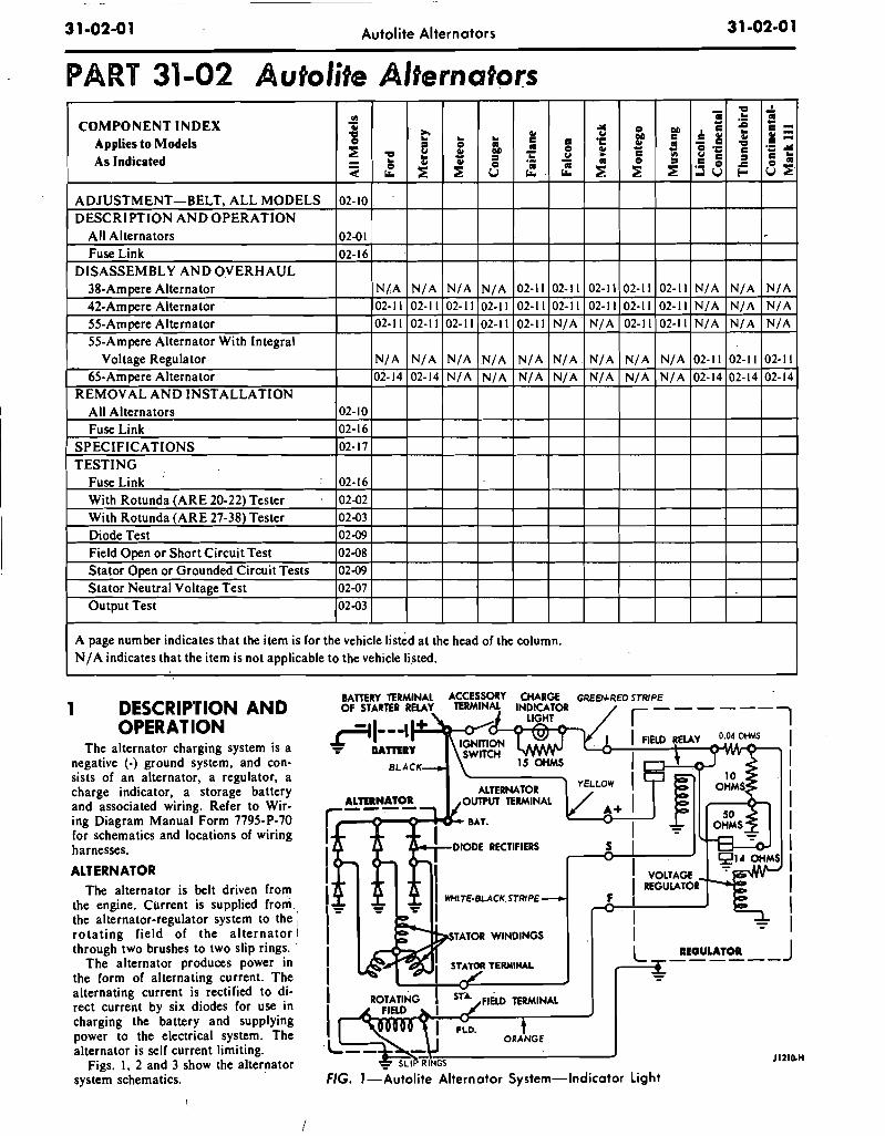
31-02-01 Autolite Alternators
PART 31-02 Autolite Alternatflrs III
COMPONENT INDEX 'ii .III CI DII 1 ~ G/ ~
Applies to Models .. .. .. I: I: ·c DII I: ~ CI , G/ ..
~ ~ ~ .. CI G/ .. ..
As Indicated "a .. ~ "C ~ • c: III .. G/ G/ .; .. ell CI ~
;( CI ~ ~
CI ~ ~ ~ "'" U "'" "'"
ADJUSTMENT-BELT, ALL MODELS 02-10.
DESCRIPTION AND OPERATION All Alternators 02-01
Fuse Link 02-16
DISASSEMBLY ANDOVERHAUL 38-Ampere Alternator N/A N/A N/A N/A 02-11 02-11 02-11 02-11 02-11
42-Ampere Alternator 02-11 02-11 02-11 02-11 02-11 02-11 02-11 02-11 02-11
55-Ampere Alternator 02-11 02-11 02-11 02-11 02-11 N/A N/A 02-11 02-11
55-Ampere Alternator With Integral Voltage Regulator N/A N/A N/A N/A N/A N/A N/A N/A N/A
65-Ampere Alternator 02-14 02-14 N/A N/A N/A N/A N/A N/A N/A REMOVAL AND INSTALLATION
All Alternators 02-10
Fuse Link 02-16
SPECIFICATIONS 02-17
TESTING Fuse Link 02-16
With Rotunda (ARE 20-22) Tester 02-02
With Rotunda (ARE 27-38) Tester 02-03
Diode Test 02-09
Field Open or Short Circuit Test 02-08
Stator Open or Grounded Circuit Tests 02-09
Stator Neutral Voltage Test 02-07
Output Test 02-03
A page number indicates that the item is for the vehicle listed at the head of the column. N / A indicates that the item is not applicable to the vehicle li,sted.
1 DESCRIP'nON AND OPERATION
The alternator charging system is a negative (-) ground system, and consists of an alternator, a regulator, a charge indicator, a storage battery and associated wiring. Refer to Wiring Diagram Manual Form 7795-P-70 for schematics and locations of wiring harnesses.
ALTERNATOR The alternator is belt driven from
the engine. CUrrent is supplied from. the alternator-regulator system to the \' rotating field of the alternator through two brushes to two slip rings ..
The alternator produces power in the form of alternating current. The alternating current is rectified to direct current by six diodes for use in charging the battery and supplying power to the electrical system. The alternator is self current limiting.
Figs. I, 2 and 3 show the alternator system schematics. .
":' 5 LI P RINGS
ACCESSORY TERMINAl
AlTERNATOR OUTPUT TERMINAl
DIODE RECTIFIERS
GRE~RED STRJPE
s
F
FIG. l-Autolite Alternator System-Indicator Light
31-02-01
.. "a ..!. .. .. .. :s .. -II: =
I: .. ~ -G/ -_ c:
"a CI .:: I: .:: "f ~ c: ~ I: .. .: CI .c: ~~ ...lU ~
.
N/A N/A N/A N/A N/A N/A N/A N/A N/A
02-11 02-11 02-11
02-14 02-14 02-14
J1210-H

31-02-02
BATTERY TERMINAL OF STARTER RELAY
.rl---I ~ IAnERY
Autolite Alternators
NOT USED WIT H AMMETER
~
,------, I 004 OHMS I I I
USED WITH I I SHUNT TYPE
A~EnR I I A+ I I S I I
GREEN-RED STRIPE
F
I I I I I I I -=- I I L REGULATOR J ------
JI20S,G
FIG. 2-Autolite Alternator System-Ammeter
r-------
31';02-02
SHUNT A~ETER
IGNITION SWITCH
TO OTHER CIRCUITS +--...... ~,... .---,
~ RADIO NEGA TIVE DIODE SUPPRESSION
CAPACITOR
FIELD COIL SLlP.RINGS
ALTERNATOR
FIG. 3-Autolite Alternator System-With Integral Regulator
2 AUTOLITE ALTERNATOR TESTING
Refer to the Ford Car and Truck Diagnosis Manual for diagnosjs of the Autolite alternator system.
Check the alternator drive belt and adjust it to specification (Section 7 in this part), before proceeding witll any
BLACK· RED STRIPE
\
GREEN· RED STRIPE
+ -=-12.VOLT -=-BATTERY
JI«I9·B
tests. Check and tighten all COMectors at the starter relay and battery.

31-02-03 Autolite Alternators 31-02-03
,.
[ IGN·]t 'AT. J ["ATO'] [ 'IElD ][ REGJ GREEN GREEN
. GREEN GREEN GREEN
[ 0100, ]] r SHORT ]
RED INDICATOR LAMP RED
~ REG. J o
CIRCUIT SELECTOR.:..;Hi-:=:---------_f{! SWITCH
o AMMETER
CONNECT TO REGULATOR MOUNTING SCREW
FOR USE WITH AMMETER TYPE CIRCUITS
FIG. 4-ARE 20-22 Tester
TESTS USING THE ROTUNDA ARE 20~22 ALTERNATOR REGULATOR TESTER
The general procedure is to connect the tester (Fig. 4), to the charging system, start the engine, make two tests, and then compare the pattern of lights that appear on the· tester to each set of patterns shown on two charts (Figs. 5 and 6). Follow the instructions. given with the ARE 20-22 tester. The ARE 20-22 tester cannot be used to test the alternator with the integral regulator.
TESTS USING THE ROTUNDA ARE 27-38 VOLT-AMPALTERNATOR TESTER
The following test procedures make
use o'f the Rotunda Volt AmpAlternatoJ Te'ster ARE 27-38.
Refer to Wiring Diagram Manual Form 7795-P-70 for schematics and locations of wiring harnesses. Use care when connecting any test equipment to the alternator system, as the alternator output terminal. is connected to the battery at all times.
ALTERNATOR OUTPUT TEST ON ENGINE
When the alternator output test is conducted orf the car, a test bench must be used. Follow the procedure given by. the test bench equipment manufacturer. When the alternator is removed from the vehicle for this purpose always disconnect the battery ground cable as the alternator output
RED
CONNECT TO REGULATOR
J 1398·"
connector is connected to the battery at all times.
To test the output of the alternator on the vehicle, proceed as follows:
Alternators Without An Integral Regulator
I. Check the alternator drive belt tension. Place the transmission in neutral or park and apply the parking brake. Make the connections and tester knob adjustments as shown in Fig. 7 Output Test. Be sure that the field rheostat knob is at the OFF position at the start of this test.
2. Close the battery adapter switch. Start the engine, then open the bat" tery adapter switch.
3. Increase the engine speed to approximately 2000 rpm (use a tachom-

1965/72
FORD CARFINAL ISSUE
May, 1975 FINAL ISSUE
COPYRIGHT 1975 -- FORD MOTOR -- DEARBORN, MICHIGANCOMPANY
5236
and Accessories
CATALOG
Form
S
cand Accessories
orm
S
DCACA
SourcCCc CCATCATDocum
nnd Acced Acce
Docum Acc Accntcent
CCCACATCA
AAd AcAccAcccc
Ford Publica i n m FP
35 B
essorieessorie
TALOGLOG
blication ALALLOGLOGGGm P
eses
FPssssosso
35 B
ALOGG
esso
LOG
essssorsorii

> t"" >-'l t:rJ
~ ~ '2 t:rJ t:rJ ('") t:rJ Z t:rJ ;S t"" f;
........ ,j) C11
~~ < '.0 ;:: ~
, C11
'" a> o a> C11
~ ~
>-'l >< :g ~ t"
34903-5 (X-96)
44716-5 IX-15) 10A340
~. ' * 374933-5 -.J (WW-116)
264805 10351-al . rr3~71 c--
(
_ 068·5
U-168) ." (MM.171
1 34903-5 (X-96) .... IIi4 .~. \ 10A381
34053-S(M-156)~ l.~'/) J 1 *10121~
/'~ 55736-5 '
(M.96.FI
/' . 10A381
('~ ~ 10334X"*8701
~
\60,65 AMP.)
371693-5 (XX-154)
"~0347
10344 (X-68)
43250·5 (U.701
51764-5 (U-366)
&--34052-5(M-1 ~ $::: 34802-5 (X-59)
. --...J 351
~,~ B'y
~ "QD)'''!Si~'''''-S 10A~81 I I
(BB-645-C)
.23 26-5
/53 AMP.I
P-5741
of:>.
"';: ... ,.. nc -t", -... O. Z~ ... ::! 00 Oz
~ I R '" ~ '" i;l
Illustrations
Note
Extracts of most of the electrical components are included!

> t"'
~ S! > g ~ t:l ... en
:.;~ "'t"' ~>-l ~I ...,
co ".. 1<1
".. en en en
g . '" ... ~ ~
,~,-~30
~, ~-
379201_5 (UU-S2-E)
10A310
---• SERVICED ONLY IN ASSY. - GROUP 10304 t ALSO SUPPLIED IN 10304 RECTIFIER ASSEMBLY
% ALSO SUPPLIED IN 10334 REAR HOUSING ASSEMBLY
P-450B
~ ~ Q =-! =;::
Ill,. ... ,. nc -ttll - ... O. z. -::! 00 Oz
'"

~ ~ t"l !:tI Z
~ !:tI
;;j o ~
~t;) a> .... -0'" '::>< N~
-:l
'" '" ~ 'u
*10370 34801.-5 (X-60) ~4) %.103.4 7
\ 351l!56-5 (XX- / I 10351
\ 10Jl!9 '/( 10349
.\ I· JIG, '03" ,.fr1. ...... ,,";" ~~:r. .%10J47
. Y~ *10350
34053-5 ." ~'n' Dfr4. .. , ..... (M-'156/ 108372 V--40917 -s .1 08367 ".",) *'/~lf.)
34055., (M.158!lOL 34805-5
/ 34053-5
(X-~~~483~~) / T~!\ (XX-85-7- f1
(M-156) , ... 34803-5 (X-60) 10329 I ~
351256-5 (XX-54) ,
t ALSO SUPPLIED IN 10304 RECTIFIER A5SEM8L Y -SUPPLIED ONLY IN 10304 RECTIFIER A55EM8L Y
%AI-SO SUPPLIED IN 10347 BRUSH REPAIR KIT • AI_SO SUPPlIED IN 108363 COVER & BRUSH ASSEMBLY
10333
10A310
10344
351496-5 (XX-306)
P-5394

HOW TO READHOW TO READWIRINGWIRING
DIAGRAMSDIAGRAMSVOL 68 S7 L2A

HOW TO READ WIRING DIAGRAMS COURSE 13001 • VOL. 68 57 L2A
TABLE OF CONTENTS INTRODUCTION
A LOGICAL APPROACH TO ELECTRICAL DIAGNOSIS.
Like reading a road map . . . . . . . . . . . . . . . . How wires are numbered and color -coded. . . . . .
CIRCUIT - A COMPLETE ELECTRICAL PATH BETWEEN TWO POINTS
2 -wire circuit. . . . . Single wire circuit . . Ground connections.
OPEN CIRCUITS
Shorts .. Grounded circuit. . Series and parallel open circuits
BREAKS IN PARALLEL CIRCUITS .
Common points . . . . . . . Splices ............. . Fuses and circuit breakers. . . Quick disconnects . . . . . . Male and female elements . Types of quick disconnects.
HINTS FOR TRACING WIRES THROUGH A DRAWING
Curve directions .. ...... . Common points Switches .. Relays ..... . Assemblies . . . Locating the assembly Finding the wire .
SUMMARY . ....... .
Page
1
2 2
5
6 6 7
8
9 9
10
11
14 15 17 18 20 22
23
23 24 25 26 28 29 30
31
The descriptions, testing procedures, and specifications in this handbook were
in effect at the time the handbook was approved for printing. Ford Motor Com
pony reserves the right to discontinue models at any time, or change specifica
tions, deSign, or testing procedures without notice and without incurring obligations.
NATIONAL SERVICE OFFICE FORD DIVISION
eM. FIRST PRINTING - JANUARY, 1968
© 1968 FORD MOTOR COMPANY DEARBORN. MICHIGAN

INTRODUCTION
The Why and Wherefore of Wiring Diagrams
To the uninformed, a wiring diagram - or a wiring assemblylooks like it might take a genius to figure out.
Not so - as you'll find out when you get better acquainted with these subjects.
There're as understandable and logical as a road map and road markers, when you're finding your way on a cross-country drive.
The ability to read a wiring diagram and relate it to a vehicle's wiring system is, of course, an essential part of a modern service technician's skill. And it's growing in relative importance, too, due to owner's increasing demands for the comforts and conveniences supplied by electrically - operated options and accessories. This opens up greater opportunities, for the forward-looking technician.
The Purpose of this Booklet . ..
. . . is to acquaint you with the systems by which electrical circuits are traced on vehicles. Specifically, it is designed to help you acquire the ability to make your own power checks, quickly and accurately.
Scope of the Booklet
Basically, this is a printed version of the film, "How to Read a Wiring Diagram." It is in no sense a manual of the shop methods by which electrical repairs are made.
It can be a helpful guide that can introduce you to the principles of wiring diagrams and vehicle wiring. As you gain experience in reading wiring diagrams, you'll accumulate your own know-how in this important skill. When it becomes" second nature" to you, these pages will have served their purpose - and yours.
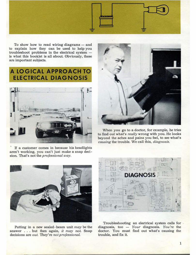
To show how to read wiring diagrams - and to explain how they can be used to help you troubleshoot problems in the electrical system -is what this booklet is all about. Obviously, these are important subjects.
A LOGICAL APPROACH TO ELECTRICAL DIAGNOSIS
I~--. -~-0~--
•
. IT a customer comes in because his beadlights a ren' t working, you can't just make a snap decision. That's not the professional way.
1~
Putting in a new sealed- beam unit may be the answer ... but then again, it may not. Snap decisions are out. They're not professional.
When you go to a doctor, for example, he tries to find out what' s really wrong with you. He looks beyond the aches and pains you fee l, to see wh at' s causing the trouble. We call this, diagnosis.
Troubleshooting an electrical system calls for diagnosis, too - Your diagnosis. You're the doctor. You must find out what's causing the trouble, and fix it.
I
LOGICAL
APPROACH
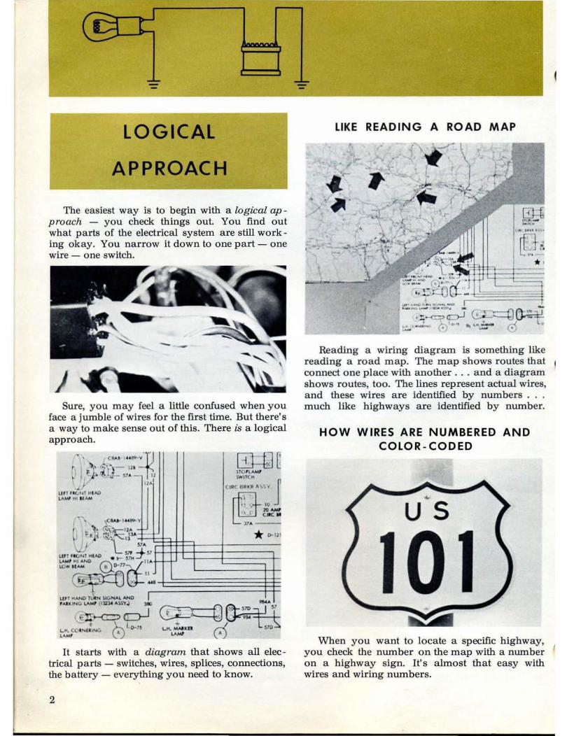
The easiest way is to begin with a logical ap proach - you check things out. You find out what parts of the electrical system are still work ing okay. You Darrow it down to one part - ODe wire - one switch.
- -)
Sure, you may feel a little confused when you face a jumble of wires for the first time. But there's a way to make sense out of this. There is a logical approach.
. . ( ..... " ..... ~ , I ~:)' r.;'j' - 111
I ~tt p o. 12
• UA' if
lilt "(>'" ~ I "" ......., .. ,u_
It s tarts with a diagram that shows all electrical parts - switches, wires, splices, connections, the battery - everything you need to know.
2
LIKE , / ..
' ~ . •
READING A ROAD
'-# ,. 1 ,.- l
.,;.. "-'¥-1. - •
" .• ,;~ r
MAP
..... . rtl-" ~ •• J
••
Reading a wiring diagram is something like reading a road map. The map shows routes that connect one place with another . .. and a diagram shows routes, too. The lines represent actual wires, a nd these wires are identified by numbers . . . much like highways are identified by number.
HOW WIRES ARE NUMBERED AND COLOR - CODED
~
US
\\Then you want to locate a specific highway, you check the number on the map with a number on a highway sign. U's almost that easy with wires a nd wiring numbers.

~[ "~ }'WIT""
tltlC eR~ ,, ~~ Y J ~1 "
~ ... OJ. e e l
".-* IHl
You find the number you want on the wiring diagram.
WIRING COLOR CODE
BASIC WIRE COLOR STRIPE NUMBER
ORANGE RED 8, 447 GREEN RED 10,10A,443 BLACK YELLOW 1l,llA GREEN BLACK 12, 12A, 12B,
12C RED BLACK 13, 13A I ORANGE YELLOW 8 BLACK 14,57 THRU
57H, 48, 48A VIOLET 77,441,441A BLACK RED 140,140A,
140B
Then you find the number on the wiring color code. It tells you what color the wire should be.
Here's the wire you're looking for. This wire is an electrical path, a path that goes from one specific place to another.
You try to follow the wire, but it soon disappears into a bundle of wires that's tightly bound with black tape. How do you find out where it goes from here?
3