Demag DRS wheel block system - … DRS Wheel Block...lower edge of gearbox or motor 28 2.7 Wheel –...
204
39144 Demag DRS wheel block system 203 352 44 714 IS 845 250810 enGB
Transcript of Demag DRS wheel block system - … DRS Wheel Block...lower edge of gearbox or motor 28 2.7 Wheel –...

39144
Demag DRS wheel block system
203 352 44 714 IS 845250810 enGB
2033
521y
_en_
2508
10.in
dd
2
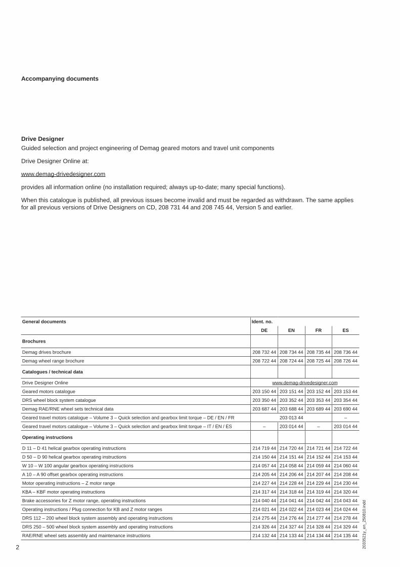
Accompanying documents
General documents Ident. no.
DE EN FR ES
Brochures
Demag drives brochure 208 732 44 208 734 44 208 735 44 208 736 44
Demag wheel range brochure 208 722 44 208 724 44 208 725 44 208 726 44
Catalogues / technical data
Drive Designer Online www.demag-drivedesigner.com
Geared motors catalogue 203 150 44 203 151 44 203 152 44 203 153 44
DRS wheel block system catalogue 203 350 44 203 352 44 203 353 44 203 354 44
Demag RAE/RNE wheel sets technical data 203 687 44 203 688 44 203 689 44 203 690 44
Geared travel motors catalogue – Volume 3 – Quick selection and gearbox limit torque – DE / EN / FR 203 013 44 –
Geared travel motors catalogue – Volume 3 – Quick selection and gearbox limit torque – IT / EN / ES – 203 014 44 – 203 014 44
Operating instructions
D 11 – D 41 helical gearbox operating instructions 214 719 44 214 720 44 214 721 44 214 722 44
D 50 – D 90 helical gearbox operating instructions 214 150 44 214 151 44 214 152 44 214 153 44
W 10 – W 100 angular gearbox operating instructions 214 057 44 214 058 44 214 059 44 214 060 44
A 10 – A 90 offset gearbox operating instructions 214 205 44 214 206 44 214 207 44 214 208 44
Motor operating instructions – Z motor range 214 227 44 214 228 44 214 229 44 214 230 44
KBA – KBF motor operating instructions 214 317 44 214 318 44 214 319 44 214 320 44
Brake accessories for Z motor range, operating instructions 214 040 44 214 041 44 214 042 44 214 043 44
Operating instructions / Plug connection for KB and Z motor ranges 214 021 44 214 022 44 214 023 44 214 024 44
DRS 112 – 200 wheel block system assembly and operating instructions 214 275 44 214 276 44 214 277 44 214 278 44
DRS 250 – 500 wheel block system assembly and operating instructions 214 326 44 214 327 44 214 328 44 214 329 44
RAE/RNE wheel sets assembly and maintenance instructions 214 132 44 214 133 44 214 134 44 214 135 44
Drive DesignerGuided selection and project engineering of Demag geared motors and travel unit components
Drive Designer Online at:
www.demag-drivedesigner.com
provides all information online (no installation required; always up-to-date; many special functions).
When this catalogue is published, all previous issues become invalid and must be regarded as withdrawn. The same applies for all previous versions of Drive Designers on CD, 208 731 44 and 208 745 44, Version 5 and earlier.

CatalogueDemag DRS wheel block system
Demag Cranes & Components GmbH constantly works on improving its products. For this reason, we reserve the right to incorporate changes in line with technical progress and which do not detract from the quality of our products. Therefore, diagrams and technical information may not always correspond to the latest design.
Reproduction of this catalogue, in whole or in part, is sub-ject to our prior consent.
Drives make materials handling systems moveDemag Cranes & Components has used its own drive technology for more than 125 years to ensure peak per-formance in materials handling solutions.
As a world leader, we offer the most comprehensive range of products in the industry. These include drives with solutions for a wide variety of requirements, such as starting and stopping motions, positioning, travel or vari-able speed drives.
3
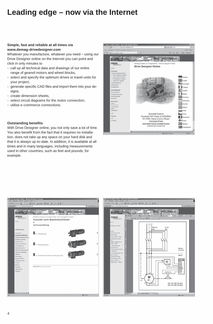
Leading edge – now via the Internet
Simple, fast and reliable at all times via www.demag-drivedesigner.com Whatever you manufacture, whatever you need – using our Drive Designer online on the Internet you can point and click in only minutes ton call up all technical data and drawings of our entire
range of geared motors and wheel blocks,n select and specify the optimum drives or travel units for
your project, n generate specifi c CAD fi les and import them into your de-
signs, n create dimension sheets, n select circuit diagrams for the motor connection, n utilise e-commerce connections.
Outstanding benefi tsWith Drive Designer online, you not only save a lot of time. You also benefi t from the fact that it requires no installa-tion, does not take up any space on your hard disk and that it is always up-to-date. In addition, it is available at all times and in many languages, including measurements used in other countries, such as feet and pounds, for example.
4

The system also ensures that your enquiry is sent quickly to the relevant engineer and also avoids any data transfer errors. The spare parts you need are sent to you reli-ably and on schedule via our Demag Shop Internet order system.
Whatever you wantDrive Designer online generates your CAD fi les in 2D or 3D for any of the many thousand geometric variants you select when confi guring your solution. The fi les are auto-matically sent to you via e-mail as exact scale drawings.
If you want to view the fi les, you can download our DXF viewer. Using the layer defi nition function, you can ensure that the fi les match the standards in your drawings.
5
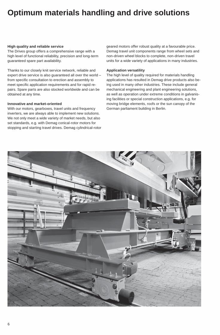
High quality and reliable serviceThe Drives group offers a comprehensive range with a high level of functional reliability, precision and long-term guaranteed spare part availability.
Thanks to our closely knit service network, reliable and expert drive service is also guaranteed all over the world – from specifi c consultation to erection and assembly to meet specifi c application requirements and for rapid re-pairs. Spare parts are also stocked worldwide and can be obtained at any time.
Innovative and market-orientedWith our motors, gearboxes, travel units and frequency inverters, we are always able to implement new solutions. We not only meet a wide variety of market needs, but also set standards, e.g. with Demag conical-rotor motors for stopping and starting travel drives. Demag cylindrical-rotor
geared motors offer robust quality at a favourable price. Demag travel unit components range from wheel sets and non-driven wheel blocks to complete, non-driven travel units for a wide variety of applications in many industries.
Application versatilityThe high level of quality required for materials handling applications has resulted in Demag drive products also be-ing used in many other industries. These include general mechanical engineering and plant engineering solutions, as well as operation under extreme conditions in galvanis-ing facilities or special construction applications, e.g. for moving bridge elements, roofs or the sun canopy of the German parliament building in Berlin.
Optimum materials handling and drive solutions
6

72033
521a
_en_
2508
10.in
dd
1
2 Demag DRS wheel block system Selection
3 Demag DRS wheel block system Data and dimensions
4 Demag DRS wheel block system Options and accessories
5 Demag DRS wheel block system Specifi cation
6 Appendix
6
5
4
3
2
Order form
Service
1 Demag DRS wheel block system Description
Selection example
Load
Operating time
large partial loadmedium partial loadmedium dead load
L 2
1

8 2033
521a
_en_
2508
10.in
dd
1Contents
1 Introduction 121.1 DRS 112 to 200 product description 121.2 DRS 250 to 500 product description 131.3 Modular wheel block system 141.4 Drive arrangements, A offset gearboxes / W angular gearboxes 151.5 Prohibited practises, improper use 161.6 Friction bearing arrangement 161.6.1 Friction bearings (DRS 112 – 200) 161.6.2 Friction bearings (DRS 250 – 500) 161.7 Travel wheel materials 171.8 Paint fi nish 181.9 Aligning system for top connection 191.10 Permissible horizontal loads for DRS wheel blocks 201.11 Reduction factor for driven wheel blocks 20
2 Demag DRS wheel block system – selection 22
2.1 Type designation key (example) for basic wheel blocks 222.2 Load spectra 242.3 Wheel block size selection 242.4 Wheel block system drive combinations 262.5 Gearbox-motor assignment for ZI central drive unit, inside arrangement 272.5.1 Central drive unit, inside arrangement, with offset geared motors 272.5.2 Central drive unit, inside arrangement, with angular geared motors 272.6 Ground clearance between wheel tread surface and
lower edge of gearbox or motor 282.7 Wheel – rail system 342.7.1 Travel wheel types 342.7.2 Assessment of rail types 362.7.3 Manufacturers’ tolerances 362.7.4 Wheel treads/crane rail widths 372.7.5 Linear contact 382.7.6 Point contact 482.7.7 Travel wheel with Hydropur tyre 542.7.8 Polyamide PA6G travel wheels 55
3 Data and dimensions 563.1 Data and dimensions DRS 112 – 200 563.2 Data and dimensions DRS 250 – 500 583.3 Travel wheel variants and shapes
Wheels for guided travel 603.3.1 Travel wheel for V rail 603.3.2 Travel wheel with concave tread 603.3.3 Travel wheel with middle guide fl ange 613.3.4 Travel wheel with convex tread with no fl anges 613.3.5 Hardened travel wheels 613.4 DRS 112 – 200 top connection 62 DRS 250 – 500 top connection 633.5 DRS 112 – 200 side connection 64 DRS 250 – 500 side connection 653.6 DRS 112 – 200 pin connection 663.6 DRS 200 pin connection with AD. 50/WU. 60 gearbox 683.6 DRS 250 – 500 pin connection 693.7 DRS 112 – 250 end connection 703.8 Axial retaining arrangement with track gauge adjustment 723.9 Pin set 733.10 Welded plate 74
92033
521a
_en_
2508
10.in
dd
1
3.11 Shaft system 753.11.1 Individual drive unit, offset gearbox 763.11.2 Central drive unit inside arrangement (ZI), offset gearbox 773.11.3 Individual drive unit, angular gearbox 783.11.4 Central drive unit inside arrangement (ZI), angular gearbox 793.11.5 Central drive unit inside arrangement (ZI), DRS 500 803.12 Splined shaft type A 823.13 Splined shaft type DFW 823.14 Connecting shaft type G 833.15 Shafts – coupling K 843.16 Universal shaft F 853.17 Journal shafts, offset and angular gearboxes 90Offset gearbox, direct input, 2 and 3-stage3.18 Dimensions of travel drive with offset geared motor, direct input 923.18.1 DRS 112 – 200 wheel block with offset gearbox and ZBF/ZBA motor 923.18.2 DRS 250 – 500 wheel block with offset gearbox and ZBF/ZBA motor 94Angular gearbox, direct input3.19 Dimensions of travel drive with angular geared motor, direct input 963.19.1 DRS 112 – 200 wheel block with angular gearbox and ZBF/ZBA motor 963.19.2 DRS 250 – 500 wheel block with angular gearbox and ZBF/ZBA motor 100Offset gearbox, coupling connection, 2 and 3-stage3.20 Dimensions of travel drive with offset geared motor,
coupling connection 1123.20.1 DRS 112 – 200 wheel block with offset gearbox and KBF/KBA motor 1123.20.2 DRS 250 – 500 wheel block with offset gearbox and KBF/KBA motor 115Angular gearbox, coupling connection3.21 Dimensions of travel drive with angular geared motor,
coupling connection 1213.21.1 DRS 112 – 200 wheel block with angular gearbox and KBF/KBA motor 1213.21.2 DRS 250 – 500 wheel block with angular gearbox and KBF/KBA motor 128
4 Options and accessories 1484.1 MA/MW torque brackets 1484.2 Torque bracket set 1504.3 D2 torque bracket 1514.4 Buffer 1534.4.1 Buffer dimensions 1534.4.2 DPZ cellular plastic buffer 1544.4.3 DPG rubber buffer 1544.4.4 DPH hydraulic buffer 1554.5 Buffer dimensions 1564.5.1 Buffer elements, DPZ cellular plastic buffer 1564.5.2 Buffer elements, DPG rubber buffer 1584.5.3 DPH hydraulic buffer 1604.6 Guide rollers 1624.6.1 General 1624.6.2 Horizontal guide rollers, DRS 112 – 200 1624.6.3 Horizontal guide rollers, DRS 250 – 500 1644.7 Shaft protection 1664.8 Options 1674.8.1 Regreasing tapered roller bearings, DRS 250 – 500 1674.8.2 Anti-friction bearing with double-lip seals, DRS 112 – 200 1684.8.3 Travel wheels with hardened treads 1684.8.4 Special paint fi nish 1684.8.5 Temperature +70°C to +150°C DRS 250 – 500 1684.8.6 Bore holes through top connection surface 1684.8.7 Rail cleaning system 1694.8.8 Alignment device 169

10 2033
521a
_en_
2508
10.in
dd
1
5 Specifi cation 170
5.1 Travel drives 1705.1.1 Number of cycles, relative duty factor and starting frequency 1705.1.2 Effi cient travel speed 1725.1.3 Combination:
travel wheel/travel speed/transmission ratio 1735.1.4 Full load hours based on the group of mechanisms 1735.2 Travel resistance (friction bearings) 1745.2.1 GJS (GGG) spheroidal graphite cast iron travel wheels 1745.2.2 Hydropur travel wheels 1745.2.3 Polyamide travel wheels 1745.2.4 Travel wheels for V rails 1755.2.5 Concave travel wheels 1755.3 Determining the maximum permissible wheel load 1765.3.1 Determining the mechanisms according to duty 1765.3.2 Determining according to the group of mechanisms 1785.3.3 Estimating the wheel block service life 1795.3.4 Determining according to the number of service life load cycles
for wheel blocks and connections to DIN 15018 1795.3.5 Determining the number of load cycles 1805.4 Selection example permissible wheel load 1815.5 Selection example wheel block components 1835.5.1 Project description 1835.5.2 Known data 1835.5.3 Determining the group of mechanisms and the number of
service life load cycles 1845.5.4 Checking the wheel block selection 1865.5.5 Determining the number of service life load cycles 1875.5.6 Determining the permissible wheel load 1885.5.7 Buffer selection 1885.5.8 Guide arrangement 1895.5.9 Select the drive variant 1905.5.10 Travel wheel slip torque 1975.5.11 Select the drive shaft 1985.5.12 Determine the type key 1985.5.13 Special measures 1985.5.14 Select the components 198
6 Appendix 1996.1 Notes on ordering 1996.2 Enquiry/order 2006.3 Project data sheet 2016.4 Drive representatives and agencies abroad 2026.5 Terms and conditions of sale and delivery 202

112033
521a
_en_
2508
10.in
dd
1
12 2033
521b
_en_
2508
10.in
dd
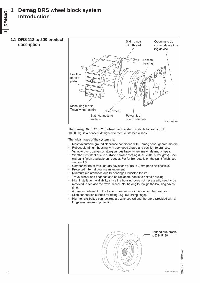
11 Demag DRS wheel block system Introduction
The Demag DRS 112 to 200 wheel block system, suitable for loads up to 10,000 kg, is a concept designed to meet customer wishes.
The advantages of the system are:• Most favourable ground clearance conditions with Demag offset geared motors.• Robust aluminium housing with very good shape and position tolerances.• Variable basic design by fi tting various travel wheel materials and shapes.• Weather-resistant due to surface powder coating (RAL 7001, silver grey). Spe-
cial paint fi nish available on request. For further details on the paint fi nish, see section 1.8.
• Compensation of track gauge deviations of up to 3 mm per side possible.• Protected internal bearing arrangement.• Minimum maintenance due to bearings lubricated for life.• Travel wheel and bearings can be replaced thanks to bolted housing.• High installation availability since the housing does not necessarily need to be
removed to replace the travel wheel. Not having to realign the housing saves time.
• A damping element in the travel wheel reduces the load on the gearbox.• Sixth connection surface for fi tting (e.g. switching fl ags).• High-tensile bolted connections are zinc-coated and therefore provided with a
long-term corrosion protection.
1.1 DRS 112 to 200 product description
Splined hub profi le to DIN 5480
Measuring mark: Travel wheel centre
Sliding nuts with thread
Opening to ac-commodate align-ing device
Position of type plate
Polyamide composite hub
Travel wheel
Friction bearing
Sixth connecting surface
41641045.eps
41621345.eps

132033
521b
_en_
2508
10.in
dd
1
1.2 DRS 250 to 500 product description
The Demag DRS 250 to 500 wheel block system, suitable for loads up to 40,000 kg, is designed as a heavy-duty travel unit based on the same principle as the smaller 112 – 200 series.
The advantages of the system are:• Most favourable ground clearance conditions with Demag offset geared motors.• A robust spheroidal graphite cast iron housing with precisely machined connect-
ing surfaces.• Variable basic design by fi tting various travel wheel materials and shapes.• For details on the paint fi nish, see section 1.8. • Possible compensation of track gauge deviations up to 4 mm or skewing up to
14 ‰.• Protected internal bearing arrangement featuring tapered-roller bearings.• Minimum maintenance due to bearings lubricated for life.• The friction bearing arrangement is prepared for re-lubrication and re-lubrication
sets can be simply added later on.• Travel wheel and bearings can be replaced thanks to bolted housing, without
the housing having to be removed.• High installation availability since the housing does not necessarily need to be
removed to replace the travel wheel. Not having to realign the housing saves time.
• The torque bracket, designed to match the wheel block, reduces peak loads which occur as a result of the travel wheel slipping torque.
• High-tensile bolted connections are zinc-coated and therefore provided with a long-term corrosion protection.
Travel wheelSixth connecting surface
Splined hub pro-fi le to DIN 5480
Position of type plate
Friction bearing

14 2033
521b
_en_
2508
10.in
dd
1
1.3 Modular wheel block system
The patented modular wheel block system is an optimum combination of drives and rail-guided travel units. The system is used for tasks such as supporting, guid-ing and driving loads. All fi ttings feature connection arrangements which have been proven over decades.
DRS wheel block
MA torque bracket MW torque bracket
A . . offset geared motors WU . angular geared motors
Individual drive unit
Central drive unit
Individual drive unit Central drive
unit
Connection variants
Top con-nection
Side con-nection Box sec-
tion girderEnd con-nection
Hub variants
Splined hubs
Travel wheel variants Guide rollers/fi ttings
Travel wheel splined profi le
Buffer
A B C D E F
A GJS (GGG) with fl ange on both sidesB GJS (GGG) without fl angeC Polyamide without fl ange, with larger diameterD GJS (GGG) with fl ange on one sideE GJS (GGG) without fl ange, with larger diameterF Hydropur without fl ange, with larger diameter
41803945.epsSee section 1.7 for information on travel wheel materials
Connection variants
Top con-nection
Side con-nection Box sec-
tion girderDRS 250 end connection
Pin connection Pin connection
152033
521b
_en_
2508
10.in
dd
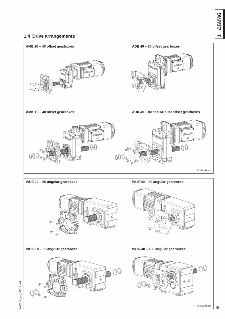
11.4 Drive arrangements
AME 10 – 40 offset gearboxes
WUE 10 – 50 angular gearboxes
42098244.eps
42098344.eps
ADE 40 – 80 offset gearboxes
AMK 10 – 40 offset gearboxes ADK 40 – 80 and AUK 90 offset gearboxes
WUK 10 – 50 angular gearboxes
WUE 40 – 80 angular gearboxes
WUK 40 – 100 angular gearboxes

16 2033
521b
_en_
2508
10.in
dd
1
1.6.2 Friction bearings (DRS 250 – 500)
42017644.eps
Tapered roller bearings Standard:The friction bearings of DRS 250 – 500 wheel blocks are protected and ar-ranged inside the wheel block housing. The compact tapered roller bearing with NILOS and V sealing rings saves space despite the high radial and axial load capability and is fi lled with grease ready for application. The housing and travel wheel arrangement provide an addi-tional trap system. The bearing is lubri-cated for life. Suitable for temperatures from -20 º C to +70 º C and normal ambient conditions.
Standard:The friction bearings of DRS 112 – 200 wheel blocks are protected and ar-ranged inside the wheel block housing. This bearing arrangement features grooved ball bearings that are lubricat-ed for life and sealed, reducing mainte-nance to a minimum, and are particu-larly suitable for high axial loads.Suitable for temperatures from –20° C to +70° C and normal ambient condi-tions.
1.6 Friction bearing ar-rangement
1.6.1 Friction bearings (DRS 112 – 200)
Options:Use low-maintenance grooved ball bearings with double-lip seals for ex-treme moist conditions. Suitable for temperatures from -20° C to +110° C and normal ambient conditions.
41125044.eps 41628244.eps
1.5 Prohibited practises, improper use
Under the following operating conditions, malfunctions, failure or hazard to life and limb may occur, e.g. in the case of:• Acidic, corrosive air as coolant• Explosion hazard atmospheres• Operation outside the permitted temperature range• Exceeding the permissible load• Exceeding the design service life• Operation under prohibited ambient conditions• Use of connecting elements not designed for use with the wheel block• Use of non-genuine Demag parts• Non-compliance with the assembly instructions• Bolted connections which are not tightened with the specifi ed torque• Incomplete assembly of connecting elements• Occurrence of peak loads which were not considered in the design
Note: Please contact the manufacturer for special operating conditions.
Safety measures must not be rendered inoperative or modifi ed or used contrary to the purposes for which they are intended.
Options:Relubrication with fl at lubrication nipple or relubrication line, see section 4.8. Tem-perature range + 70° C to 150° C ambient temperature with use of hot bearing grease, Viton (FPM) - V- sealing ring and screw plug in the lubrication opening.

172033
521b
_en_
2508
10.in
dd
1
EN-GJS-700-2 (GGG 70)
1.7 Travel wheel materials
Travel wheels with Hydropur tyre
GJS-700-2 (GGG 70) is a spheroidal graphite cast iron, a material with a self-lubri-cating effect owing to the graphite incorporated in it. Therefore, the travel wheels feature high wear resistance with low travel resistance, thus minimising wear on the rail. The high inherent damping effect of the travel wheels guarantees good running characteristics for the travel unit. Travel wheels with guide features, e.g. fl ange-guided, with a tread distance to the travel rail of min. 1 mm and guide roller arrangement with identical distance are available. If extreme wear is expected, e.g. casting sand or similar, the travel wheel tread surface or guide fl ange can be hard-ened to 56 ± 2 HRc. Hardening is intended only to minimise wear.
Hydropur is a polyurethane elastomer which features good resistance to hydrolys-es compared to other conventional polyurethanes (such as Vulkollan, for example). This material features signifi cantly higher friction values compared to GJS (GGG) wheels, thus making travel wheels with a Hydropur tyre predestined for highly dy-namic applications. Running noises are reduced to a minimum owing to the good dampening characteristics: Attention must be paid to the considerably reduced permissible load capacities compared to wheels of GJS-700-2 (GGG 70). Wheels with Hydropur tyres are particularly suitable for operation on concrete surfaces ow-ing to the low contact area pressure or in the case of particularly high acceleration rates of up to 1,5 m/s2 for friction drives due to the high friction coeffi cient between the travel wheel tyre and counterpart material. This material can be used at up to 100 ºC for high temperature applications.
Compared to GJS-700-2 (GGG 70) travel wheels, travel wheels made of polya-mide (PA 6 casting) feature signifi cantly reduced travel noise for comparable fric-tion values. Attention must also be paid to the signifi cantly reduced permissible load capacity compared to travel wheels made of GJS-700-2 (GGG 70). Owing to the high specifi c contact pressure as a result of the round shape, polyamide is only suitable for operation on steel materials or similar.
Polyamide
Travel wheels with hardened treads
For operating conditions in which increased travel wheel wear is likely (e.g. rails with extreme dirt accumulation), the running surfaces and fl anges of the spheroidal graphite cast iron travel wheels can be hardened (to a depth of 2 to 3 mm). Travel wheel sizes 112 – 200 do not feature fl ange wear indicators. Surface hard-ening is 56 ± 2 HRc.
suitable O partially suitable – not suitable
Application of the various travel wheel types Properties
Spheroidal graphite cast
ironHydropur Polyamide stainless
High acceleration with friction connection above 0,5 m/s2 O O O
High acceleration as positive connection above 0,5 m/s2 – –
High pressure: wheel/rail – –
Counterpart material: steel
Counterpart material: aluminium O O
Counterpart material: concrete / screed – – –
Counterpart material: wood O –
Temperature up to 110 ºC (DRS 112 to 200) O – O O
Temperature up to 150 ºC (DRS 250 to 500) O – – O
High humidity at high temperatures O O O
Outdoor operation with ice and snow O O
18 2033
521b
_en_
2508
10.in
dd
1
1.8 Paint fi nishStandard
Special paint fi nish
DRS 112 to 200The aluminium wheel block housings are provided with a weather-resistant powder coating in RAL 7001 (silver grey) with a minimum thickness of 90 μm before leav-ing the factory.Continuous coating quality is ensured by our works standard for wheel block hous-ings (ident. no. 012 326 99).DRS 250 to 500Primer coat: Single coat of silver grey paint, coat thickness approx. 40 μm Finish coat: Silver grey RAL 7001, 50% shine, approx. 50 μm
DRS 112 to 200For special paint fi nishes, wheel blocks can be supplied with a dual component PUR fi nish coat at the request of the customer. If the paint fi nish is to be applied by the customer, attention must be paid to the works standard for special paint fi nish on powder-coated wheel block surfaces (ident no. 012 328 99).DRS 250 to 500For non-standard RAL colours, a corresponding fi nish coat may be applied to wheel blocks at the request of the customer.Special paint fi nishes on request.
DRS 112 to 200The surfaces of wheel blocks with a powder-coated fi nish may be used in environ-ments with acid vapours without any treatment. Wheel blocks must also be fi tted with ball bearings featuring double lip seals. The gap between the housing and the cover is seated with an acid-proof varnish.DRS 250 to 500Wheel blocks can be supplied with an acid protection paint fi nish for applications in environments with acid vapours.
Acid-resistant paint fi nish

192033
521b
_en_
2508
10.in
dd
1
• Fast and optimum alignment of wheel blocks using the Demag alignment de-vice.
• Reduced wear thanks to exactly aligned travel wheels. Achievable accuracy with measuring device: 1,6 ‰.
• The sliding nut arrangement (DRS 112 to DRS 200) or the difference between the threaded pin diameter to the bore hole diameter of the connecting structure (DRS 250 to DRS 500) offers a lateral alignment path of ± 3 mm.
For further details: see assembly, installation and operating instructions, ident. no. 214 827 44
1.9 Aligning system for top connection
41621344.eps
Laser
Target markerSlot aperture
Laser beam
DRS 112 to 500

20 2033
521b
_en_
2508
10.in
dd
1
for rail material fSt travel wheel material GJS-700-2 (GGG 70)
Rail
MaterialDIN EN 10025
Factor fSt
Linear contact Point contact
St 70-2/E 360 1 1
St 60-2/E 335 1 0,44
St 52-3/S 355 J 2 G 3 1 0,38
St 37-2/ S 235 J R 0,25 0,01
Convex travel wheel – straight rail or straight travel wheel – curved rail
• Wheel blocks with fl ange guide arrangement The permissible horizontal force on fl ange-guided wheel blocks must not ex-
ceed 20 % of the actual wheel load.
• Wheel blocks with roller guide arrangement The permissible horizontal force on wheel blocks fi tted with a roller guide ar-
rangement must not exceed 15 % of the actual wheel load. For DRS 112 – DRS 200 with travel wheel variant E, the value must be limited to 12 %.Exception: DRS 200 with top connection, the permissible horizontal force must be limited to 10% of the actual wheel load. If higher horizontal loads are to be expected, the roller guide arrangement can be fi tted to the steel superstructure, however, not to the wheel block.
• Wheel blocks with roller guide arrangement, fi tted to the customer’s superstructure
The guide roller arrangement as a solo part may transmit 20 % of the actual wheel load when fi tted to the customer’s superstructure.
1.10 Permissible horizontal loads for DRS wheel blocks
A uniform temperature-dependent reduction factor fK is used for the entire wheel block.
1.11 Reduction factors for driven wheel blocks
for temperature fK
DRS wheel block size
– 20 ºC up to
+ 40 ºC
up to 50 ºC
up to 60 ºC
up to 70 C
up to 80 ºC
up to 90 ºC
up to 100 ºC
up to 110 ºC
up to 120 ºC
up to 130 ºC
up to 140 ºC
up to 150 ºC
DRS 112 – 200 driven
1 0,85 0,8 0,75 0,6 a. A. a. A. a. A. – – – –
DRS 112 – 200 not driven
1 a. A. a. A. a. A. a. A. a. A. a. A. a. A. – – – –
DRS 250 – 500 1 1 0,92 0,90 0,88 0,86 0,84 0,82 0,80 a. A. a. A. a. A.
A reduction factor fST is introduced for linear or point contact depending on the material of the rail.
a. A. = On request

212033
521b
_en_
2508
10.in
dd
1
22 2033
522a
_en_
2508
10.in
dd
2
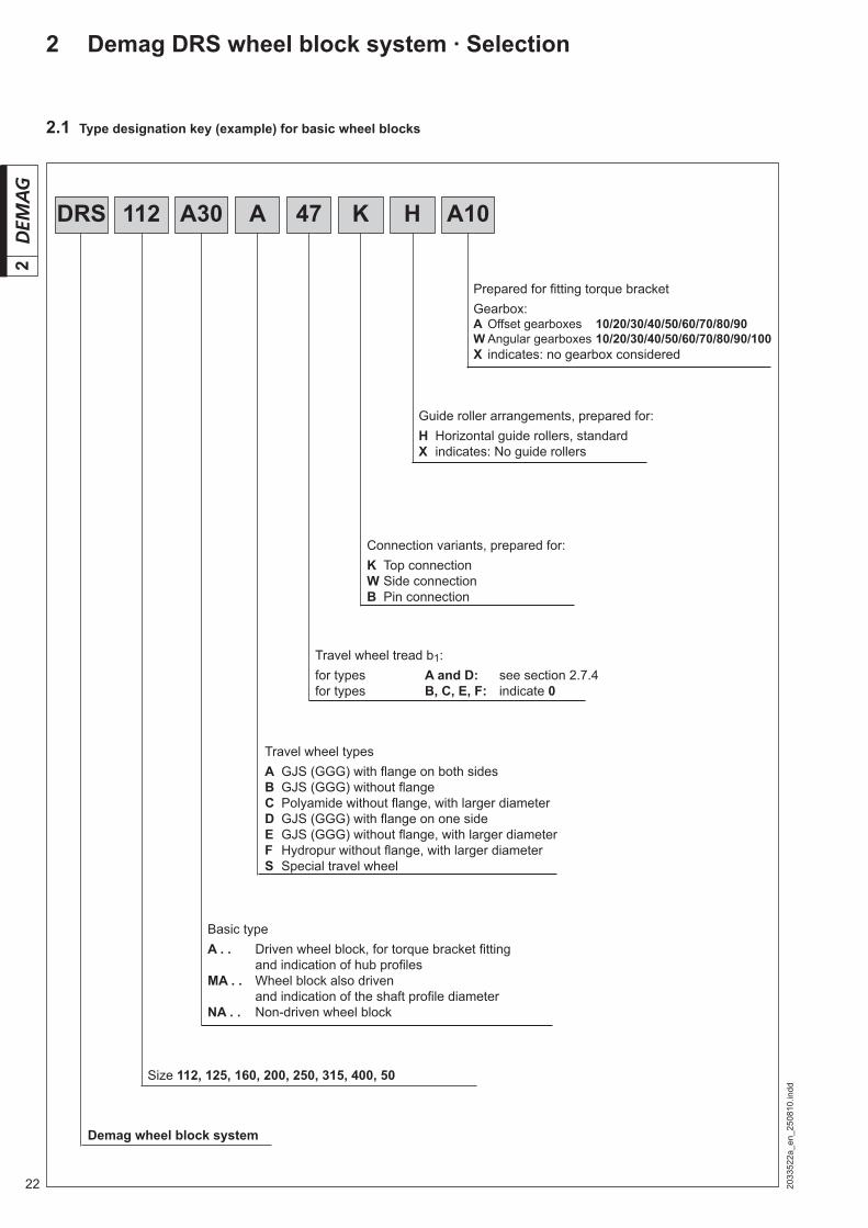
DRS 112 A30 A 47 K H A10
2.1 Type designation key (example) for basic wheel blocks
2 Demag DRS wheel block system · Selection
Prepared for fi tting torque bracket Gearbox:A Offset gearboxes 10/20/30/40/50/60/70/80/90W Angular gearboxes 10/20/30/40/50/60/70/80/90/100X indicates: no gearbox considered
Guide roller arrangements, prepared for:H Horizontal guide rollers, standardX indicates: No guide rollers
Connection variants, prepared for:K Top connectionW Side connectionB Pin connection
Travel wheel typesA GJS (GGG) with fl ange on both sidesB GJS (GGG) without fl angeC Polyamide without fl ange, with larger diameterD GJS (GGG) with fl ange on one sideE GJS (GGG) without fl ange, with larger diameterF Hydropur without fl ange, with larger diameterS Special travel wheel
Travel wheel tread b1:for types A and D: see section 2.7.4for types B, C, E, F: indicate 0
Basic typeA . . Driven wheel block, for torque bracket fi tting
and indication of hub profi lesMA . . Wheel block also driven
and indication of the shaft profi le diameterNA . . Non-driven wheel block
Size 112, 125, 160, 200, 250, 315, 400, 50
Demag wheel block system
232033
522a
_en_
2508
10.in
dd
2
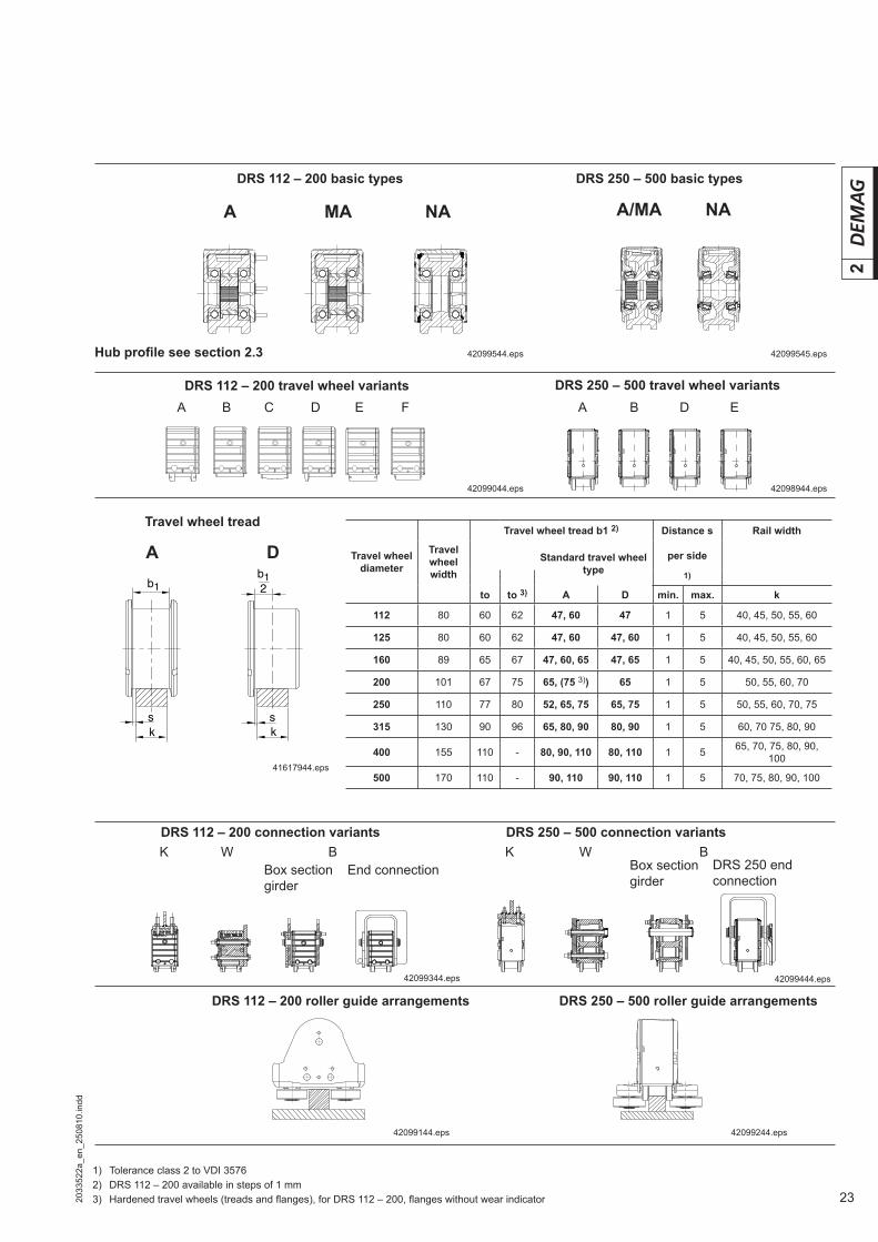
DRS 112 – 200 basic types
DRS 112 – 200 travel wheel variants
Travel wheel tread
DRS 112 – 200 connection variants
DRS 112 – 200 roller guide arrangements
A B C D E F
A D
42099044.eps
41617944.eps
42099344.eps
42099144.eps 42099244.eps
42099544.eps
DRS 250 – 500 travel wheel variants
42098944.eps
A B D E
DRS 250 – 500 roller guide arrangements
DRS 250 – 500 connection variants
42099444.eps
A MA NA
42099545.eps
A/MA NA
DRS 250 – 500 basic types
Hub profi le see section 2.3
End connection
Travel wheel diameter
Travel wheel width
Travel wheel tread b1 2) Distance s Rail width
Standard travel wheel type
per side
1)
to to 3) A D min. max. k
112 80 60 62 47, 60 47 1 5 40, 45, 50, 55, 60
125 80 60 62 47, 60 47, 60 1 5 40, 45, 50, 55, 60
160 89 65 67 47, 60, 65 47, 65 1 5 40, 45, 50, 55, 60, 65
200 101 67 75 65, (75 3)) 65 1 5 50, 55, 60, 70
250 110 77 80 52, 65, 75 65, 75 1 5 50, 55, 60, 70, 75
315 130 90 96 65, 80, 90 80, 90 1 5 60, 70 75, 80, 90
400 155 110 - 80, 90, 110 80, 110 1 5 65, 70, 75, 80, 90, 100
500 170 110 - 90, 110 90, 110 1 5 70, 75, 80, 90, 100
1) Tolerance class 2 to VDI 35762) DRS 112 – 200 available in steps of 1 mm3) Hardened travel wheels (treads and fl anges), for DRS 112 – 200, fl anges without wear indicator
K W BBox section girder
DRS 250 end connection
K W BBox section girder
sk
b12b1
ks

24 2033
522a
_en_
2508
10.in
dd
2
2.2 Load spectra
Medium (0,5 < k ≤ 0,63):Mechanisms, or parts thereof, usually subject to light loads, but with a higher incidence of maximum load.
Light (k ≤ 0,5):Mechanisms, or parts thereof, usually subject to light loads and occasional maximum loads.
Heavy (0,63 < k ≤ 0,8):Mechanisms, or parts thereof, usually subject to medium loads, and frequent-ly to maximum loads.
Very heavy (0,8 < k ≤ 1):Mechanisms, or parts thereof, usually subject to maximum or almost maxi-mum loads.
Load
Operating time
small partial load small deadload
L 1
Load
Operating time
large partial load medium partial load medium deadload
L 2
Load
Operating time
large deadload
L 3
Operating time
Load
very large deadloadL 4
Refer to the permissible wheel load tables for linear contact (section 2.7.5) for more detailed information on groups of mechanisms 1 Am, 2 m, ..., 5 m.
Quick selection of wheel block sizes depending on the loads to be displaced ac-cording to groups of mechanisms and travel speed.The basis for selection is the maximum useful rail head width for fl at rails.
2.3 Wheel block size selection
Average daily operating time in hours
Load spectrum ≤ 0,25 ≤ 0,5 ≤ 1 ≤ 2 ≤ 4 ≤ 8 ≤ 16 > 16
Light k ≤ 0,50 – – – 1 Bm 1 Am 2 m 3 m 4 m
Medium k ≤ 0,63 – – 1 Bm 1 Am 2 m 3 m 4 m 5 m
Heavy k ≤ 0,80 – 1 Bm 1 Am 2 m 3 m 4 m 5 m –
Very heavy k ≤ 1 1 Bm 1 Am 2 m 3 m 4 m 5 m – –

252033
522a
_en_
2508
10.in
dd
2
Group of mechanisms/load factor group Travel speed in m/min
FEM 3 m 2 m 1 Am 1 Bm12,5 16 20 25 31,5 40 50 63 80 100 125 160
ISO M 6 M 5 M 4 M 3
Mas
s in
kg
per w
heel
blo
ck fo
r fl a
t rai
ls w
ith m
ax. u
sefu
l rai
l hea
d w
idth
01140 01440 01810 02280
01240 01560 01970 02480 11201340 01680 02120 02670
01440 01810 02280 02750
01580 01990 02500 03150
01710 02090 02720 03420
01840 02320 02930 03690 12501990 02500 03150 03970
02150 02710 03420 04300
02320 02930 03690 04650
02500 03150 03970 05000
02900 03650 04520 05560
03150 03960 04870 06000 16003390 04230 05210 06410
03650 04520 05570 06850
03950 04850 05980 07000
04350 04900 06040 07440
04720 05290 06510 08010
05080 05650 06960 08570 20005480 06040 07440 09160
05930 06490 07990 09840
06340 06960 08570 10000
06450 07200 08860 10910
06730 08290 10200 12560
07200 08860 10910 13430 25007730 09520 11720 14430
08290 10200 12550 15470
09520 11720 14430 16000
12050 12920 13850 16410
12360 13240 14350 17670
12640 13540 15340 18890 31512920 13850 16410 20200
13230 14310 17620 21700
13540 15340 18890 22000
17480 19390 20980 25830
18540 19880 22590 27810 40018960 20320 24150 29740
19390 20980 25830 30000
21668 24792 28041 34523
23120 25411 30197 37176 50024244 26225 32287 39750
24792 28041 34523 40000

26 2033
522a
_en_
2508
10.in
dd
2
2.4 Wheel block system drive combinations with offset and angular geared motors
● = Combination with solid shaftsO = Combination with splined hollow shaft for splined shafts– = not possible
Note:Check that the shaft coupling and mo-tor housing do not collide for central drive arrangements with offset geared motors according to 2.5.1.
DRS wheel block size
112 125 160 200 250 315 400 500
Hub profi le N 30 N 30 N 35 N 35 N 45 N 45 N 50 N 50 N 65 N 65 N 75 N 75 N 90 N 90 N 110Travel wheel
material
GJS
-700
-2
Pol
yam
ide
Hyd
ropu
r
GJS
-700
-2
Pol
yam
ide
Hyd
ropu
r
GJS
-700
-2
Pol
yam
ide
Hyd
ropu
r
GJS
-700
-2
Pol
yam
ide
Hyd
ropu
r
GJS
-700
-2
Pol
yam
ide
Hyd
ropu
r
GJS
-700
-2
Pol
yam
ide
Hyd
ropu
r
GJS
-700
-2
Pol
yam
ide
Hyd
ropu
r
GJS
-700
-2
GJS
-700
-2
GJS
-700
-2
GJS
-700
-2
GJS
-700
-2
GJS
-700
-2
GJS
-700
-2
GJS
-700
-2
Gearbox size
A 10 / W 10 ● ● ● ● ● – – – – – – – – – – – – – – – – – – – – – – – –
A 20 / W 20 O O O – – – ● – ● ● ● – – – – – – – – – – – – – – – – – –
A 30 / W 30 – – – – – – O – O – – – ● – ● ● ● – – – – – – – – – – – –
A 40 / W 40 – – – – – – – – – – – – O – O – – – ● – ● ● – – – – – – –
A 50 / W 50 / W 60 – – – – – – – – – – – – – – – – – – O – O – ● ● – – – – –
A 60 / W 70 – – – – – – – – – – – – – – – – – – – – – – O – ● ● – – –
A 70 / W 80 – – – – – – – – – – – – – – – – – – – – – – – – O – ● ● –
A 80 / W 90 – – – – – – – – – – – – – – – – – – – – – – – – – – O – ●A 90 / W 100 – – – – – – – – – – – – – – – – – – – – – – – – – – – – O
Universal shaft F ● ● ● – – – – ● – – – ● – ● – – – ● – ● – ● – ● – ● – ●

272033
522a
_en_
2508
10.in
dd
2
● = Possible combination
41862744.eps
41862544.eps
2.5 Gearbox-motor assignment for ZI central drive unit, inside arrangement
2.5.1 Central drive unit, inside arrangement, with offset geared motors
For wheel block-geared motor assignments with offset geared motors, collision of the motor with the shaft coupling must be excluded. Permissible combinations are shown in the following table.
2.5.2 Central drive unit, inside arrangement, with angular geared motors
There is no limitation for the permissible gearbox-motor combination for DRS wheel blocks with angular geared mo-tors.
Attention! Motor / terminal box position not in the direction of the central shaft.
Motor frame size
DRS wheel block size112 125 160 200 250 315 400 500
A offset gearbox size
10 20 20 30 30 40 40 50 50 60 60 70 70 80 80 90
ZBF ZBA
63A, 71A 63A/B, 71A/B ● ● ● ● ● ● ●80A 80A/B, 90A ● ● ● ● ● ● ● ● ● ● ● ● ●90B, 100A 90B, 100A/B ● ● ● ● ● ● ● ● ● ● ● ● ●112A, 132A/B 112A, 132A/B/C ● ● ● ● ● ● ● ● ●
160A/B,180A ● ● ● ● ● ●180B,200A ● ● ●225A/B ● ● ●
KBF KBA
71A, 71B 71A, 71B ● ● ● ● ● ● ● ● ● ●80A 80A/B ● ● ● ● ● ● ● ● ● ●90A 90A/B ● ● ● ● ● ● ● ● ● ● ● ●100A 100A/B ● ● ● ● ● ● ● ● ● ● ● ●112A 112B ● ● ● ● ● ● ● ● ● ● ●125A 125B ● ● ● ● ● ● ● ● ●140A 140B ● ● ● ● ● ● ● ● ●
160B ● ● ● ● ●180B ● ● ●200B ● ● ●225B ●
28 2033
522a
_en_
2508
10.in
dd
2
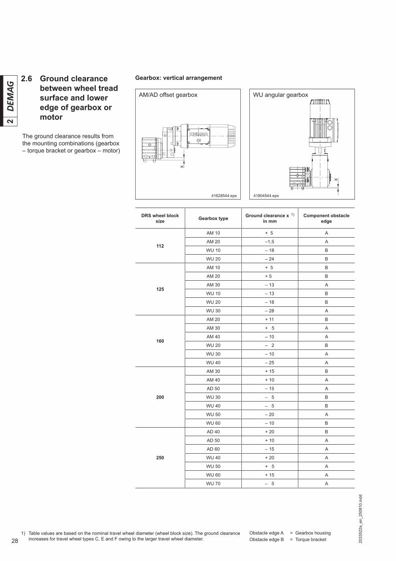
2.6 Ground clearance between wheel tread surface and lower edge of gearbox or motor
1) Table values are based on the nominal travel wheel diameter (wheel block size). The ground clearance increases for travel wheel types C, E and F owing to the larger travel wheel diameter.
41628544.eps
AM/AD offset gearbox
41804544.eps
WU angular gearbox
Gearbox: vertical arrangement
The ground clearance results from the mounting combinations (gearbox – torque bracket or gearbox – motor)
DRS wheel block size Gearbox type Ground clearance x 1)
in mmComponent obstacle
edge
112
AM 10 + 5 A
AM 20 –1,5 A
WU 10 – 18 B
WU 20 – 24 B
125
AM 10 + 5 B
AM 20 + 5 B
AM 30 – 13 A
WU 10 – 13 B
WU 20 – 18 B
WU 30 – 28 A
160
AM 20 + 11 B
AM 30 + 05 A
AM 40 – 10 A
WU 20 – 02 B
WU 30 – 10 A
WU 40 – 25 A
200
AM 30 + 15 B
AM 40 + 10 A
AD 50 – 15 A
WU 30 – 05 B
WU 40 – 5 B
WU 50 – 20 A
WU 60 – 10 B
250
AD 40 + 20 B
AD 50 + 10 A
AD 60 – 15 A
WU 40 + 20 A
WU 50 + 05 A
WU 60 + 15 A
WU 70 – 05 A
Obstacle edge A = Gearbox housingObstacle edge B = Torque bracket

292033
522a
_en_
2508
10.in
dd
2
Ground clearance between wheel tread surface and lower edge of gearbox or motor
Gearbox: vertical arrangement
DRS wheel block size Gearbox type Ground clearance x 1)
in mmComponent obstacle
edge
315
AD 50 + 29 B
AD 60 + 17 A
AD 70 – 08 A
WU 50 + 29 B
WU 60 + 29 B
WU 70 + 27 A
WU 80 – 28 A
400
AD 60 + 55 B
AD 70 + 35 A
AD 80 – 1 A
WU 70 + 55 B
WU 80 + 15 A
WU 90 – 05 A
500
AD 70 + 82 B
AD 80 + 49 A
AU 90 + 10 A
WU 80 + 65 A
WU 90 + 45 A
WU 100 – 10 A
1) Table values are based on the nominal travel wheel diameter (wheel block size). The ground clearance increases for travel wheel types C, E and F owing to the larger travel wheel diameter.
Obstacle edge A = Gearbox housingObstacle edge B = Torque bracket

30 2033
522a
_en_
2508
10.in
dd
2
Gearbox: horizontal arrangement, direct input
WU angular gearbox
41628944.eps
AM/AD offset gearbox
41628844.eps41645644.eps
AM 20 offset gearbox, turned 15º
Ground clearance between wheel tread surface and lower edge of gearbox or motor
DRS wheel block size
Gearbox type Ground clearance x1 1)
in mm to
gearbox housing
Com-ponent
ob-stacle edge
Ground clearance x2 1) in mmto motor housing depending on size
Z63 / Z71
Z80 / Z90A
Z90B / Z100 Z112 / Z132 Z160A/B /
Z180AZ180B /
Z200 Z225
112
AM 10 D + 1 A – 14 – 23 – 42 – – – –
AM 20 D/T – 10 A – 14 – 23 – 42 – – – –
WU 10 D – 18 B + 7 – 1 – – – – –
WU 20 D/T – 24 A + 10 + 2 – 18 – – – –
125
AM 10 D + 5 B – 8 – 16 – – – – –
AM 20 D/T – 3 A – 8 – 16 – 36 – – – –
AM 30 D/T – 16 A – 8 – 16 – 36 – – – –
WU 10 D – 13 B + 14 + 5 – – – – –
WU 20 D/T – 18 A + 17 + 8 – 11 – – – –
WU 30 D/T – 28 A + 20 + 11 – 8 – – – –
160
AM 20 D/T + 11 B + 10 + 1 – 18 – – – –
AM 30 D/T 0 A + 10 + 1 – 18 – – – –
AM 40 D/T – 14 A + 10 + 1 – 18 – 50 – – –
WU 20 D/T – 2 B + 34 + 26 + 6 – – – –
WU 30 D/T – 10 A + 37 + 29 + 9 – – – –
WU 40 D/T – 25 A + 38 + 30 + 10 – 22 – – –
200
AM 30 D/T + 15 B + 30 + 21 + 2 – – – –
AM 40 D/T + 5 A + 30 + 21 + 2 – 30 – – –
AD 50 D/T – 25 A + 30 + 21 + 2 – 30 – – –
WU 30 D/T – 5 B + 57 + 49 + 29 – – – –
WU 40 D/T – 5 B + 58 + 50 + 30 - 2 – – –
WU 50 D/T – 20 A + 63 + 55 + 35 + 3 – – –
WU 60 T – 105 A + 18 + 10 – 10 – 42 – – –
WU 60 Q – 105 A – 25 - 33 – 53 – 85 – – –
250
AD 40 D/T + 20 B + 55 + 46 + 27 – 5 – – –
AD 50 D/T 0 A + 55 + 46 + 27 – 5 – – –
AD 60 D/T – 20 A + 55 + 46 + 27 – 5 – – –
WU 40 D/T + 20 B + 83 + 75 + 55 + 23 – – –
WU 50 D/T + 5 A + 88 + 80 + 60 + 28 – – –
WU 60 T – 80 A + 43 + 35 + 15 – 17 – 44 – –
WU 60 Q – 80 A 0 – 8 – 28 – 60 – 87 – –
WU 70 T – 120 A + 49 + 40 + 21 – 11 – 38 – 78 – 101
WU 70 Q – 120 A – 1 – 10 – 29 – 61 – 88 – 128 – 151
1) Table values are based on the nominal travel wheel diameter (wheel block size). The ground clearance increases for travel wheel types C, E and F owing to the larger travel wheel diameter.
Obstacle edge A = Gearbox housingObstacle edge B = Torque bracket

312033
522a
_en_
2508
10.in
dd
2
Gearbox: horizontal arrangement, direct input
Ground clearance between wheel tread surface and lower edge of gearbox or motor
Note: More favourable ground clearance can be achieved when gearbox type WU 60 – 100 model B14.2/B14.8 is used
DRS wheel block size
Gearbox type Ground clear-ance x1 1)
in mm to
gearbox housing
Com-ponent
ob-stacle edge
Ground clearance x2 1) in mmto motor housing depending on size
Z63 / Z71
Z80 / Z90A
Z90B / Z100 Z112 / Z132 Z160A/B /
Z180AZ180B /
Z200 Z225
315
AD 50 D/T + 29 B + 87 + 79 + 59 + 27 – – –
AD 60 D/T + 12 A + 87 + 79 + 59 + 27 – – –
AD 70 D/T – 16 A + 87 + 79 + 59 + 27 – – –
WU 50 D/T + 29 B + 121 + 112 + 93 + 61 – – –
WU 60 T – 48 A + 76 + 67 + 48 + 16 – 11 – 51 – 74
WU 60 Q – 48 A + 33 + 24 + 5 – 27 – 54 – 94 –117
WU 70 T – 88 A + 81 + 73 + 53 + 21 – 6 – 46 – 69
WU 70 Q – 88 A +31 + 23 + 3 – 29 – 56 – 96 – 119
WU 80 T – 118 A + 55 + 47 + 27 – 5 – 32 – 72 – 95
WU 80 Q – 118 A + 5 – 3 – 23 – 55 – 82 – 122 – 145
400
AD 60 D/T + 55 B + 130 + 121 + 102 + 70 – – –
AD 70 D/T + 27 A + 130 + 121 + 102 + 70 – – –
AD 80 D/T – 11 A + 130 + 121 + 102 + 70 – – –
WU 70 T – 45 A + 124 + 115 + 96 + 64 + 37 – 3 – 26
WU 70 Q – 45 A + 74 + 65 + 46 + 14 – 13 – 53 – 76
WU 80 T – 75 A + 98 + 89 + 70 + 38 + 11 – 29 – 52
WU 80 Q – 75 A + 48 + 39 + 20 – 12 – 39 – 79 – 102
WU 90 T – 115 A + 98 + 89 + 70 + 38 + 11 – 29 – 52
WU 90 Q – 115 A + 37 + 28 + 9 – 23 – 50 – 90 – 113
500
AD 70 D/T + 77 A + 180 + 171 + 152 + 120 + 93 + 53 + 30
AD 80 D/T + 39 A + 180 + 171 + 152 + 120 + 93 + 53 + 30
AU 90 D/T 0 A + 180 + 171 + 152 + 120 + 93 + 53 + 30
WU 80 T – 25 A + 148 + 139 + 120 + 88 + 61 + 21 – 2
WU 80 Q – 25 A + 98 + 89 + 70 + 38 + 11 – 29 – 52
WU 90 T – 65 A + 148 + 139 + 120 + 88 + 61 + 21 – 2
WU 90 Q – 65 A + 87 + 78 + 59 + 27 0 – 40 – 63
WU 100 T – 140 A + 136 + 127 + 108 + 76 + 49 + 9 – 14
WU 100 Q – 140 A + 58 + 49 + 30 - 2 – 29 – 69 – 92
AM 20 offset gearbox, turned 15º
DRS wheel
block sizeGearbox type
Ground clearance x1 1)
in mmto
gearbox housing
Component obstacle
edge
Ground clearance x2 1) Ground clearance x3 1)
in mm to motor housing depending on size
Z63 / Z71 Z80 / Z90A Z90B / Z100 Z63 / Z71 Z80 / Z90A Z90B / Z100
112
AM 20 D/T
– 2 A + 3 – 6 – 28 163 173 195
125 + 5 A + 10 0 – 22 169 179 201
160 + 11 B + 27 + 18 – 4 187 197 219
1) Table values are based on the nominal travel wheel diameter (wheel block size). The ground clearance increases for travel wheel types C, E and F owing to the larger travel wheel diameter.
Obstacle edge A = Gearbox housingObstacle edge B = Torque bracket

32 2033
522a
_en_
2508
10.in
dd
2
Gearbox: horizontal arrangement, coupling connection arrangement with KB motor
Angular gearbox
41628944.eps
Offset gearbox
41831244.eps42019744.eps
AM 20 offset gearbox, turned 15º
Ground clearance between wheel tread surface and lower edge of gearbox or motor
DRS wheel block size
Gearbox type Ground clear-ance x2 1)
in mm
Com-ponent
obstacle edge
Ground clearance x2 1) in mm to motor housing depending on size
KB71 KB80 KB90 KB100 KB112 KB125 KB140 KB160 KB180 KB200 KB225
112
AM 10 D – 7 C – 14 – 23 – – – – – – – – –
AM 20 D/T – 10 A – 14 – 23 – 33 – – – – – – – –
WU 10 D – 18 B + 7 – 2 – – – – – – – – –
WU 20 D/T – 24 A + 10 + 1 – 9 – – – – – – – –
125
AM 10 D 0 C – 8 – 17 – – – – – – – – –
AM 20 D/T – 3 A – 8 – 17 – 27 – – – – – – – –
AM 30 D/T – 18 C – 8 – 17 – 27 – 36 – – – – – – –
WU 10 D – 13 B + 14 + 5 – – – – – – – – –
WU 20 D/T – 18 A + 17 + 8 – 2 – – – – – – – –
WU 30 D/T – 28 A + 20 + 11 + 1 – 8 – – – – – – –
160
AM 20 D/T + 11 B + 10 + 1 – 9 – – – – – – – –
AM 30 D/T 0 C + 10 + 1 – 9 – 18 – – – – – – –
AM 40 D/T – 14 A + 10 + 1 – 9 – 18 – – – – – – –
WU 20 D/T - 2 B + 34 + 25 + 15 – – – – – – – –
WU 30 D/T – 10 A + 37 + 28 + 18 + 9 – – – – – – –
WU 40 D/T – 25 A + 38 + 29 + 19 + 10 – 2 – 15 – – – – –
200
AM 30 D/T + 15 B + 30 + 21 + 11 + 2 – – – – – – –
AM 40 D/T + 6 A + 30 + 21 + 11 + 2 – – – – – – –
AD 50 D/T – 18 A + 30 + 21 + 11 + 2 – 10 – 23 – 37 – – – –
WU 30 D/T – 5 B + 57 + 48 + 38 + 29 – – – – – – –
WU 40 D/T – 5 B + 58 + 49 + 39 + 30 + 18 + 5 – – – – –
WU 50 D/T – 20 A + 63 + 54 + 44 + 35 + 23 + 10 – 4 – – – –
WU 60 T – 105 A + 18 + 9 – 1 – 10 – 22 – 35 – 49 – 69 – – –
WU 60 Q – 105 A – 25 + 34 – 44 – 53 – 65 – – – – – –
250
AD 40 D/T + 20 B + 55 + 46 + 36 + 27 – – – – – – –
AD 50 D/T + 7 A + 55 + 46 + 36 + 27 + 15 + 2 – 12 – – – –
AD 60 D/T – 17 A + 55 + 46 + 36 + 27 + 15 + 2 – 12 – – – –
WU 40 D/T + 20 B + 83 + 74 + 64 + 55 + 43 + 30 – – – – –
WU 50 D/T + 5 A + 88 + 79 + 69 + 60 + 48 + 35 + 21 – – – –
WU 60 T – 80 A + 43 + 34 + 24 + 15 + 3 – 10 – 24 – 44 – – –
WU 60 Q – 80 A 0 – 9 – 19 – 28 – 40 – – – – – –
WU 70 T – 120 A + 49 + 40 + 30 + 21 + 9 – 4 – 18 – 38 – 58 – 78 –
WU 70 Q – 120 A – 1 – 10 – 20 – 29 – 41 – 54 – 68 – – – –
Obstacle edge A = Gearbox housingObstacle edge B = Torque bracketObstacle edge C = Coupling housing
1) Table values are based on the nominal travel wheel diameter (wheel block size). The ground clearance increases for travel wheel types C, E and F owing to the larger travel wheel diameter.

332033
522a
_en_
2508
10.in
dd
2
Gearbox: horizontal arrangement, coupling connection arrangement with KB motor
Ground clearance between wheel tread surface and lower edge of gearbox or motor
DRS wheel block size
Gearbox type Ground clear-ance x2 1)
in mm
Com-ponent
obstacle edge
Ground clearance x2 1) in mm to motor housing depending on size
KB71 KB80 KB90 KB100 KB112 KB125 KB140 KB160 KB180 KB200 KB225
315
AD 50 D/T + 29 B + 87 + 78 + 68 + 59 + 47 + 34 + 20 – – – –
AD 60 D/T + 15 A + 87 + 78 + 68 + 59 + 47 + 34 + 20 – – – –
AD 70 D/T - 12 A + 87 + 78 + 68 + 59 + 47 + 34 + 20 0 – – –
WU 50 D/T + 29 B + 121 + 112 + 102 + 93 + 81 + 68 + 54 – – – –
WU 60 T – 48 A + 76 + 67 + 57 + 48 + 36 + 23 + 9 – 11 – – –
WU 60 Q – 48 A + 33 + 24 + 14 + 5 – 7 – 20 – 34 – 54 – – –
WU 70 T – 88 A + 81 + 72 + 62 + 53 + 41 + 28 + 14 – 6 – 26 – 46 –
WU 70 Q – 88 A + 31 + 22 + 12 + 3 – 9 – 22 – 36 – – – –
WU 80 T – 118 A + 55 + 46 + 36 + 27 + 15 + 2 – 12 – 32 – 52 – 72 –
WU 80 Q – 118 A + 5 – 4 – 14 – 23 – 35 – 48 – 62 – – – –
400
AD 60 D/T + 55 B + 130 + 121 + 111 + 102 + 90 + 77 + 63 – – – –
AD 70 D/T + 30 A + 130 + 121 + 111 + 102 + 90 + 77 + 63 + 43 – – –
AD 80 D/T - 8 A + 130 + 121 + 111 + 102 + 90 + 77 + 63 + 43 + 23 + 3 –
WU 70 T – 45 A + 124 + 115 + 105 + 96 + 84 + 71 + 57 + 37 + 17 – 3 –
WU 70 Q – 45 A + 74 + 65 + 55 + 46 + 34 + 21 + 7 – – – –
WU 80 T – 75 A + 98 + 89 + 79 + 70 + 58 + 45 + 31 + 11 – 9 – 29 –
WU 80 Q – 75 A + 48 + 39 + 29 + 20 + 8 – 5 – 19 – – – –
WU 90 T – 115 A – – – – + 58 + 45 + 31 + 11 – 9 – 29 – 52
WU 90 Q – 115 A – + 28 + 18 + 9 – 3 – 16 – 30 – 50 – – –
500
AD 70 D/T + 80 A + 180 + 171 + 161 + 152 + 140 + 127 + 113 + 93 – – –
AU 80 D/T + 42 A – + 171 + 161 + 152 + 140 + 127 + 113 + 93 + 73 + 53 –
AU 90 D/T 0 A – – – – + 140 + 127 + 113 + 93 + 73 + 53 + 30
WU 80 T – 25 A + 148 + 139 + 129 + 120 + 108 + 95 + 81 + 61 + 41 + 21 –
WU 80 Q – 25 A + 98 + 89 + 79 + 70 + 58 + 45 + 31 – – – –
WU 90 T – 65 A – – – – + 108 + 95 + 81 + 61 + 41 + 21 – 2
WU 90 Q – 65 A – + 78 + 68 + 59 + 47 + 34 + 20 0 – – –
WU 100 T – 140 A – – – – + 96 + 83 + 69 + 49 + 29 + 9 – 14
WU 100 Q – 140 A – + 49 + 39 + 30 + 18 + 5 – 9 – 29 – 49 – 69 –
AM 20 offset gearbox, turned 15º
DRS wheel block size
Gearbox type
Ground clearance x1 1)
in mmto
gearbox housing
Component obstacle edge
Ground clearance x2 1) Ground clearance x3 1)
in mm to motor housing depending on size
KB 71 KB 80 KB 90 KB 71 KB 80 KB 90
112
AM 20 D/T
– 2
A
+ 8 – 2 – 12 158 168 178
125 + 5 + 14 + 5 – 6 165 174 201
160 + 11 + 32 + 22 + 12 182 192 202
Obstacle edge A = Gearbox housingObstacle edge B = Torque bracketObstacle edge C = Coupling housing
1) Table values are based on the nominal travel wheel diameter (wheel block size). The ground clearance increases for travel wheel types C, E and F owing to the larger travel wheel diameter.
34 2033
522a
_en_
2508
10.in
dd
2
2.7 Wheel – rail system
2.7.1 Travel wheel types
A B CED FTravel wheel types, standard
Special design (made to order)
41686444.eps
Source: based on VDI 3576, July 1995
1) Verifi cation of calculation required2) Stress factor groups to DIN 15018
2.7.2 Assessment of rail types Rail shape Flat rail to
DIN 1017 or 1014DIN 536Shape A DIN 5601
Assessment criteria
41409144.eps 41409244.eps 41409344.eps
Wheel loads– small (≤ 200 kN) 1)
– medium (> 200 kN, ≤ 500 kN)– large (> 500 kN)
++O
+++
+––
Duty– light (B1, B2) 2)
– medium (B3, B4)– heavy (B5, B6)
++O
+++
++O
Rail support and assign-ment to crane runway
– steel– concrete– sleepers
+––
++–
+++
To accommodate lateral forces + + O
Lateral guid-ance
– guide rollers– fl anges
++
++
O+
For fi tting – wind drift safety devices– tilt safety devices
+–
+O
++
+ suitableO partially suitable– not suitable
GJS (GGG) with fl ange on both sides
GJS (GGG) without fl ange
Polyamide without fl ange, with larger diameter
GJS (GGG) with fl ange on one side
GJS (GGG) with-out fl ange
Hydropur with-out fl ange, with larger diameter
for V rail with concave tread
with middle guide fl ange
without fl ange, with convex tread

352033
522a
_en_
2508
10.in
dd
2
55
6
h3 h4
h2
B1
B 2 min
6h4
w
Bmin
1
Rated size Application Girder width Clearance dimension for Bore hole spacing
guide rollers
1) for rail B min h4 W
16 A 45/A 55 207/232 34/45 171/196
18 A 65/A 75 257/282 53/63 221/246
20 A 100 282 71 246
22 A 120302
79266
24 A 150 122
1) Allows for a 6 mm pad. Select the relevant rated size for other thicknesses. Use the next smaller rated size for the clamped version.
2) If horizontal guide roller arrangements are used, note the relevant dimensions in accordance with sec-tion 4.6.
Clamping plate for alignment to RIW-NO 17938
Clamping plate for crane rail to RIW-NO 17942
41946644.eps
41946544.eps
Rated size Crane rail Dimensions Tightening torque
with pad without pad
BoltNut
h3 h4 Nut
B1 B2 h2 DIN 934 DIN 936 DIN 934 DIN 936 DIN 934 DIN 936
14 –
A 45 125 245 55 14 19
M 16x40 M 16x35 205 Nm 100 Nm
A 55 150 270 65 24 29
A 65 175 295 75 34 39
A 75200 320
85 44 49
A 100 95 54 50
18
A 45
–
125 245 55 15 20
M 16x45 M 16x40 205 Nm 100 NmA 55 150 270 65 25 30
A 65 175 295 75 35 40
– A 120 220 340 105 59 64
22
A 75
–200 320
85 40 45
M 16x50 M 16x45 205 Nm 100 NmA 100 95 50 55
A 120 220 340 105 60 65
DIN 934 DIN 936 2)
2)
36 2033
522a
_en_
2508
10.in
dd
2
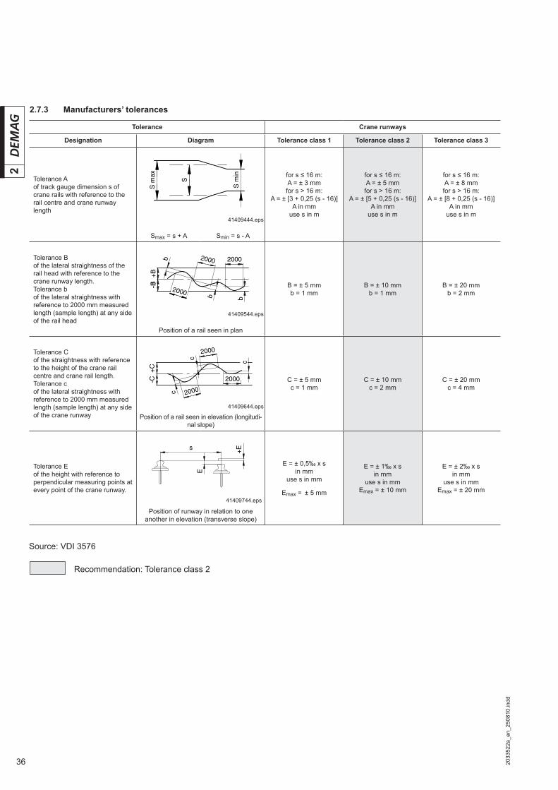
2.7.3 Manufacturers’ tolerances
Source: VDI 3576
Recommendation: Tolerance class 2
S m
in
S
S m
ax
41409444.eps
-B-B+
B
20002000
2000
b
b b
41409544.eps
2000
-C+
C
2000
2000
c
c
c
41409644.eps
s
E
+E
41409744.eps
Tolerance Crane runways
Designation Diagram Tolerance class 1 Tolerance class 2 Tolerance class 3
Tolerance Aof track gauge dimension s of crane rails with reference to the rail centre and crane runway length
Smax = s + A Smin = s - A
for s ≤ 16 m:A = ± 3 mmfor s > 16 m:
A = ± [3 + 0,25 (s - 16)]A in mm
use s in m
for s ≤ 16 m:A = ± 5 mmfor s > 16 m:
A = ± [5 + 0,25 (s - 16)]A in mm
use s in m
for s ≤ 16 m:A = ± 8 mmfor s > 16 m:
A = ± [8 + 0,25 (s - 16)]A in mm
use s in m
Tolerance Bof the lateral straightness of the rail head with reference to the crane runway length.Tolerance bof the lateral straightness with reference to 2000 mm measured length (sample length) at any side of the rail head
Position of a rail seen in plan
B = ± 5 mmb = 1 mm
B = ± 10 mmb = 1 mm
B = ± 20 mmb = 2 mm
Tolerance Cof the straightness with reference to the height of the crane rail centre and crane rail length.Tolerance cof the lateral straightness with reference to 2000 mm measured length (sample length) at any side of the crane runway Position of a rail seen in elevation (longitudi-
nal slope)
C = ± 5 mmc = 1 mm
C = ± 10 mmc = 2 mm
C = ± 20 mmc = 4 mm
Tolerance Eof the height with reference to perpendicular measuring points at every point of the crane runway.
Position of runway in relation to one another in elevation (transverse slope)
E = ± 0,5‰ x sin mm
use s in mm
Emax = ± 5 mm
E = ± 1‰ x sin mm
use s in mmEmax = ± 10 mm
E = ± 2‰ x sin mm
use s in mmEmax = ± 20 mm

372033
522a
_en_
2508
10.in
dd
2
2.7.4 Wheel treads/crane rail widths GJS-700-2 (GGG 70) spheroidal graphite cast iron travel wheel
1) Tolerance class 2 to VDI 35762) DRS 112 – 200 available in steps of 1 mm3) Hardened travel wheels (treads and fl anges), for DRS 112 – 200, fl anges without wear indicator
41617944.eps
Travel wheel diameter Travel wheel width Travel wheel tread b1 2) Distance s Rail width
Standard travel wheel typeper side
1)
to to 3) A D min. max. k
112 080 60 062 47, 60 47 1 5 40, 45, 50, 55, 60
125 080 60 062 47, 60 47, 60 1 5 40, 45, 50, 55, 60
160 089 65 067 47, 60, 65 47, 65 1 5 40, 45, 50, 55, 60, 65
200 101 67 75 65, (75 3)) 65 1 5 50, 55, 60, 70
250 110 77 80 52, 65, 75 65, 75 1 5 50, 55, 60, 70, 75
315 130 90 96 65, 80, 90 80, 90 1 5 60, 70 75, 80, 90
400 155 110 - 80, 90, 110 80, 110 1 5 65, 70, 75, 80, 90, 100
500 170 110 - 90, 110 90, 110 1 5 70, 75, 80, 90, 100
A D
sk
b12b1
ks
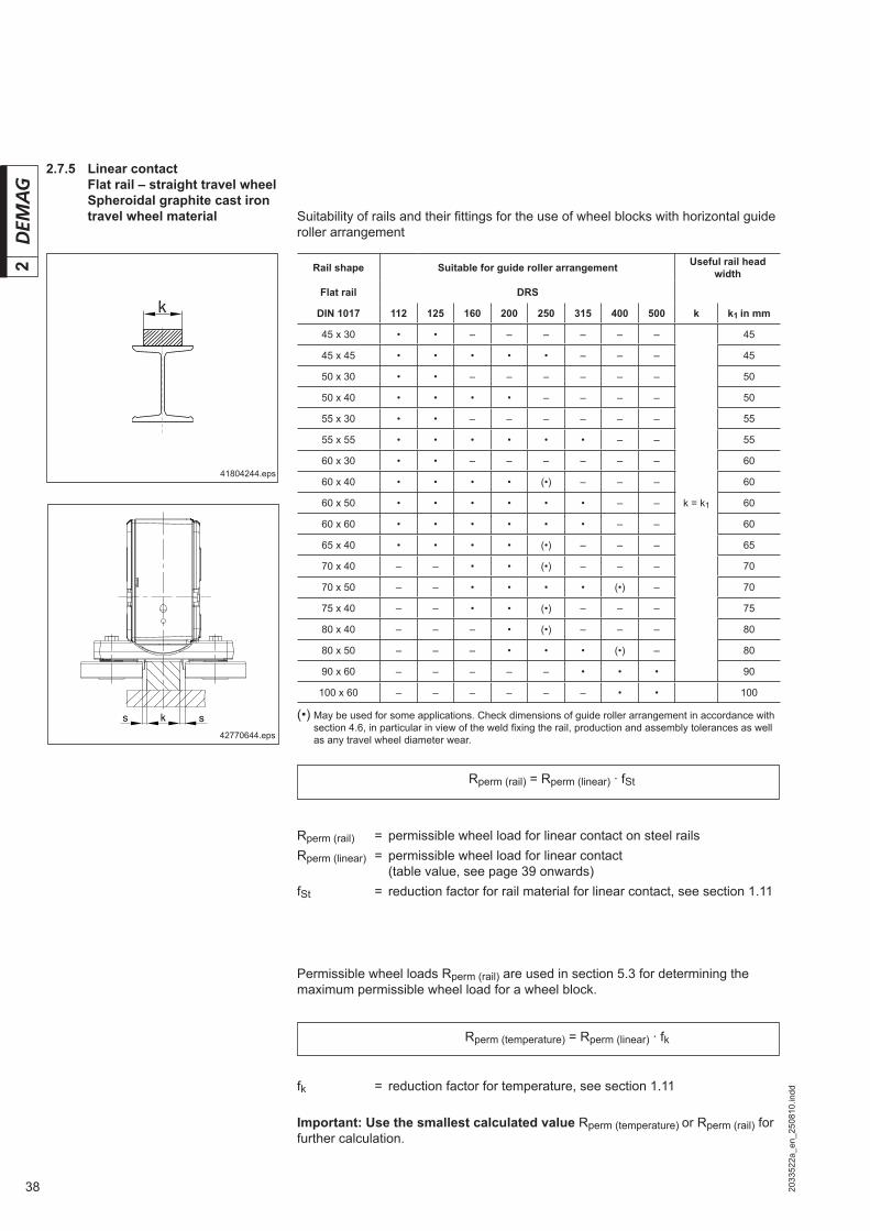
38 2033
522a
_en_
2508
10.in
dd
2 Rail shape Suitable for guide roller arrangement Useful rail head width
Flat rail DRS
DIN 1017 112 125 160 200 250 315 400 500 k k1 in mm
45 x 30 • • – – – – – –
k = k1
45
45 x 45 • • • • • – – – 45
50 x 30 • • – – – – – – 50
50 x 40 • • • • – – – – 50
55 x 30 • • – – – – – – 55
55 x 55 • • • • • • – – 55
60 x 30 • • – – – – – – 60
60 x 40 • • • • (•) – – – 60
60 x 50 • • • • • • – – 60
60 x 60 • • • • • • – – 60
65 x 40 • • • • (•) – – – 65
70 x 40 – – • • (•) – – – 70
70 x 50 – – • • • • (•) – 70
75 x 40 – – • • (•) – – – 75
80 x 40 – – – • (•) – – – 80
80 x 50 – – – • • • (•) – 80
90 x 60 – – – – – • • • 90
100 x 60 – – – – – – • • 100
Rperm (rail) = permissible wheel load for linear contact on steel railsRperm (linear) = permissible wheel load for linear contact (table value, see page 39 onwards)fSt = reduction factor for rail material for linear contact, see section 1.11
2.7.5 Linear contact Flat rail – straight travel wheel Spheroidal graphite cast iron travel wheel material
41804244.eps
Permissible wheel loads Rperm (rail) are used in section 5.3 for determining the maximum permissible wheel load for a wheel block.
fk = reduction factor for temperature, see section 1.11
Important: Use the smallest calculated value Rperm (temperature) or Rperm (rail) for further calculation.
(•) May be used for some applications. Check dimensions of guide roller arrangement in accordance with section 4.6, in particular in view of the weld fi xing the rail, production and assembly tolerances as well as any travel wheel diameter wear.
Suitability of rails and their fi ttings for the use of wheel blocks with horizontal guide roller arrangement
42770644.eps
Rperm (rail) = Rperm (linear) · fSt
Rperm (temperature) = Rperm (linear) · fk
sks

392033
522a
_en_
2508
10.in
dd
2
Linear contactSpheroidal graphite cast iron travel wheel materialTemperature range –20 ºC to +40 ºCRail material: St 70-2/E 360, St 60-2/E 335, St 52-3/S 355 J 2 G 3
DRS 112 Top and side connection
Group of mecha-nisms Useful rail
head width in mm
Permissible wheel load in kg
FEM ISOTravel speed in m/min
12,5 16 20 25 31 40 50 63 80 100 125 160
1 Bm M 3
30 2700 2520 2350 2190 2050 1910
35 2740 2560 2400 2220
402750
2720 2520 232045
50
≥ 55
1 Am M 4
30 2700 2520 2350 2190 2050 1910 1780 1670 1550
35 2740 2560 2390 2220 2080 1940 1810
402750
2720 2520 2320 2160 2000 184045
50
≥ 55
2 m M 5
30 2700 2510 2350 2190 2050 1910 1780 1660 1550 1450 1350 1260
35 2740 2560 2390 2220 2080 1940 1810 1680 1560 1430
40
2720 2520 2320 2160 2000 1840 1710 1590 146045 2750
50
≥ 55
3 m M 6
30 2200 2130 2040 1980 1870 1750 1670 1530 1400 1290 1180 1060
35 2640 2490
2320 2160 2000 1840 1710 1580 1460 1360 1260 1160
40
2720 250045
50
≥ 55
4 m M 7
30 1980 1920 1840
1720 1590 1470 1360 1260 1170 1080 1000 0920
35
2170 2000 1850
40
45
50
≥ 55
5 m M 8
30
1720 1590 1470 1370 1270 1170 1080 1000 0930 0860 0800 0730
35
40
45
50
≥ 55

40 2033
522a
_en_
2508
10.in
dd
2
Linear contactSpheroidal graphite cast iron travel wheel materialTemperature range –20 ºC to +40 ºC Rail material: St 70-2/E 360, St 60-2/E 335, St 52-3/S 355 J 2 G 3
DRS 112 Pin connection
Group of mecha-nisms Useful rail
head width in mm
Permissible wheel load in kg
FEM ISOTravel speed in m/min
12,5 16 20 25 31 40 50 63 80 100 125 160
1 Bm M 3
30 3446 3215 2993 2799 2612 2431 2303 2252 2197
35 3492 3266 3047 2836 2687
2527 2327
40
3430 3175 2932 272245 3500
50
≥ 55
1 Am M 4
30 3446 3200 2993 2799 2612 2431 2303 2250 2197 2149
2006 1847
35 3492 3266 3047 2836 2687
2520 2327 2160
40
3430 3175 2932 272245 3500
50
≥ 55
2 m M 5
30 2799 2599 2431 2303 2250 2197 2149
2000 1847 1715 1592 1466
35 3266 3033 2836 2687
2520 2327 2160
40
3430 3159 2932 272245
50
≥ 55
3 m M 6
30 2303 2247 2197 2149
2000 1847 1715 1588 1466 1361 1263 1164
35 2687
2507 2327 2160
40 2722
45
50
≥ 55
4 m M 7
30 2152
2000 1857 1724 1596 1474 1368 1267 1170 1986 1008 928
35
2172
40
45
50
≥ 55
5 m M 8
30
1728 1592 1478 1372 1270 1173 1089 1008 931 864 802 739
35
40
45
50
≥ 55
412033
522a
_en_
2508
10.in
dd
2
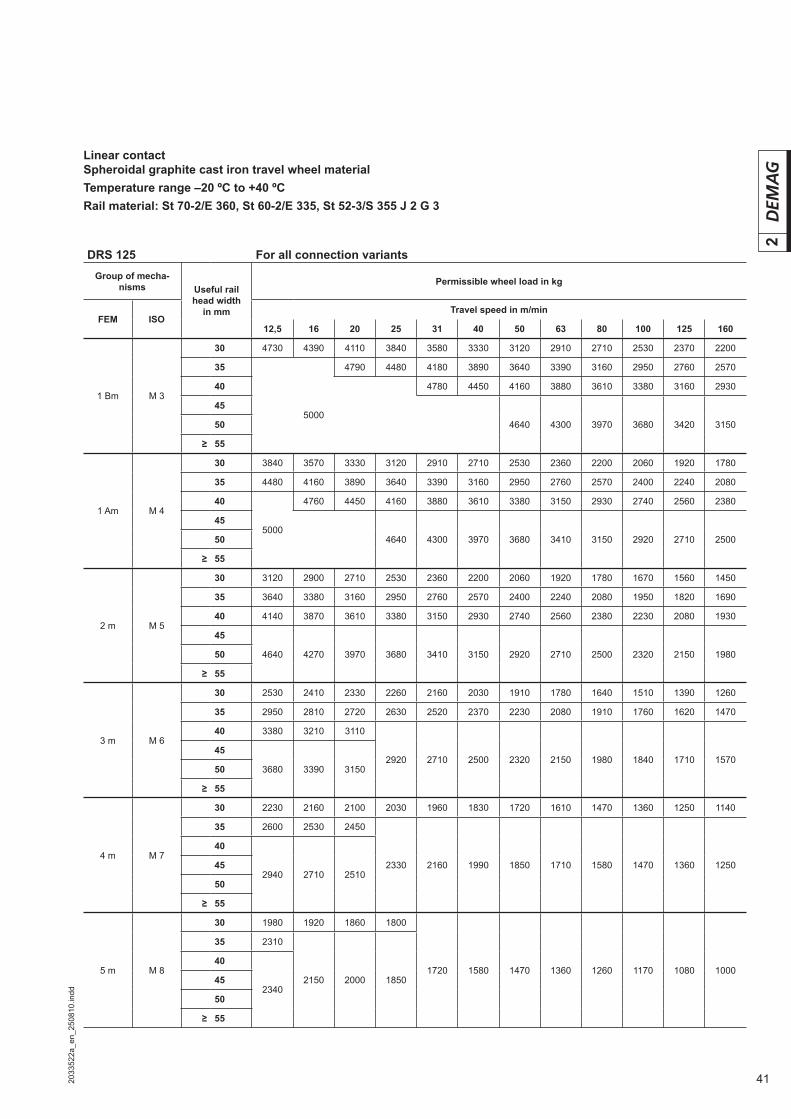
Linear contactSpheroidal graphite cast iron travel wheel materialTemperature range –20 ºC to +40 ºCRail material: St 70-2/E 360, St 60-2/E 335, St 52-3/S 355 J 2 G 3
DRS 125 For all connection variantsGroup of mecha-
nisms Useful rail head width
in mm
Permissible wheel load in kg
FEM ISOTravel speed in m/min
12,5 16 20 25 31 40 50 63 80 100 125 160
1 Bm M 3
30 4730 4390 4110 3840 3580 3330 3120 2910 2710 2530 2370 2200
35 4790 4480 4180 3890 3640 3390 3160 2950 2760 2570
40 4780 4450 4160 3880 3610 3380 3160 2930
455000
4640 4300 3970 3680 3420 315050
≥ 55
1 Am M 4
30 3840 3570 3330 3120 2910 2710 2530 2360 2200 2060 1920 1780
35 4480 4160 3890 3640 3390 3160 2950 2760 2570 2400 2240 2080
40 4760 4450 4160 3880 3610 3380 3150 2930 2740 2560 2380
455000
4640 4300 3970 3680 3410 3150 2920 2710 250050
≥ 55
2 m M 5
30 3120 2900 2710 2530 2360 2200 2060 1920 1780 1670 1560 1450
35 3640 3380 3160 2950 2760 2570 2400 2240 2080 1950 1820 1690
40 4140 3870 3610 3380 3150 2930 2740 2560 2380 2230 2080 1930
45
4640 4270 3970 3680 3410 3150 2920 2710 2500 2320 2150 198050
≥ 55
3 m M 6
30 2530 2410 2330 2260 2160 2030 1910 1780 1640 1510 1390 1260
35 2950 2810 2720 2630 2520 2370 2230 2080 1910 1760 1620 1470
40 3380 3210 3110
2920 2710 2500 2320 2150 1980 1840 1710 157045
3680 3390 315050
≥ 55
4 m M 7
30 2230 2160 2100 2030 1960 1830 1720 1610 1470 1360 1250 1140
35 2600 2530 2450
2330 2160 1990 1850 1710 1580 1470 1360 1250
40
2940 2710 251045
50
≥ 55
5 m M 8
30 1980 1920 1860 1800
1720 1580 1470 1360 1260 1170 1080 1000
35 2310
2150 2000 1850
40
234045
50
≥ 55
42 2033
522a
_en_
2508
10.in
dd
2
Linear contactSpheroidal graphite cast iron travel wheel materialTemperature range –20 ºC to +40 ºCRail material: St 70-2/E 360, St 60-2/E 335, St 52-3/S 355 J 2 G 3
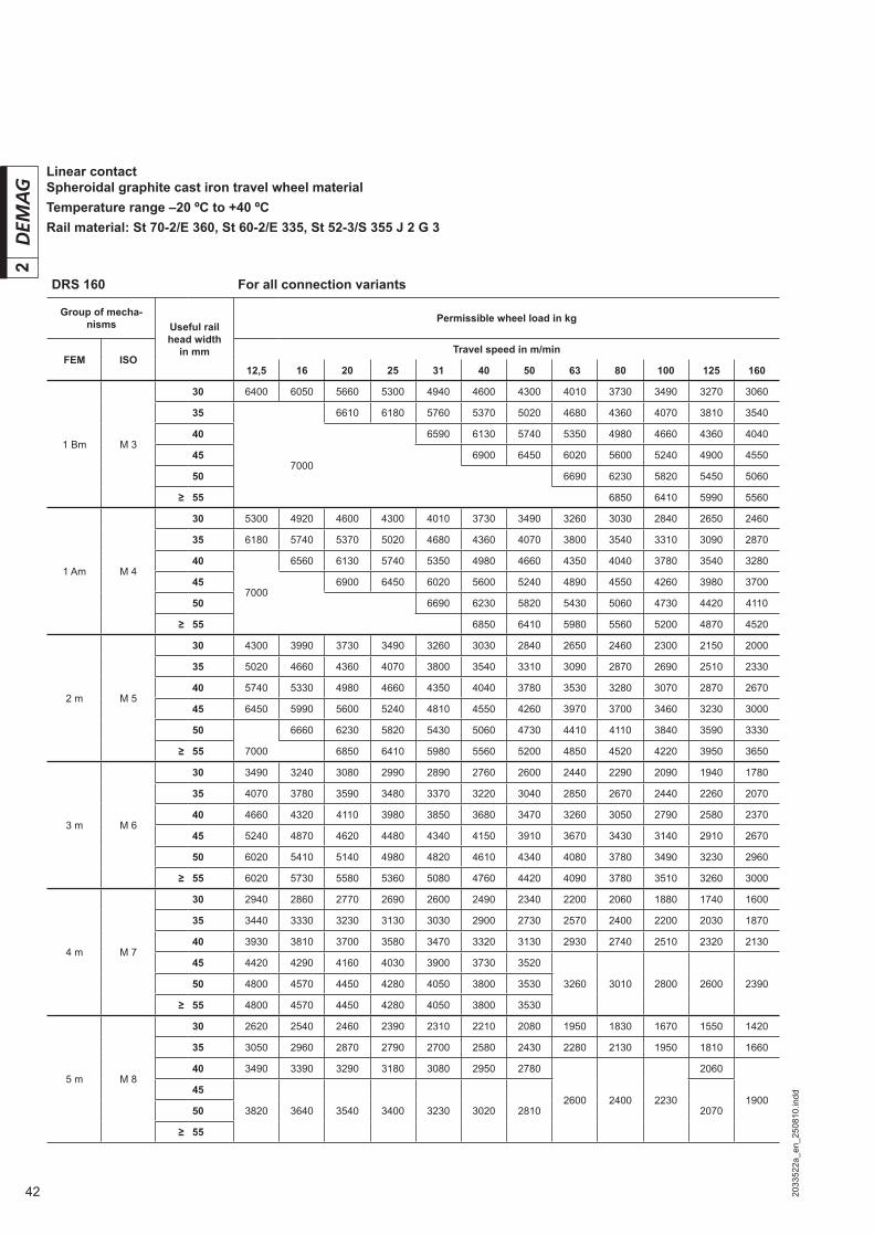
DRS 160 For all connection variants
Group of mecha-nisms Useful rail
head width in mm
Permissible wheel load in kg
FEM ISOTravel speed in m/min
12,5 16 20 25 31 40 50 63 80 100 125 160
1 Bm M 3
30 6400 6050 5660 5300 4940 4600 4300 4010 3730 3490 3270 3060
35 6610 6180 5760 5370 5020 4680 4360 4070 3810 3540
40 6590 6130 5740 5350 4980 4660 4360 4040
457000
6900 6450 6020 5600 5240 4900 4550
50 6690 6230 5820 5450 5060
≥ 55 6850 6410 5990 5560
1 Am M 4
30 5300 4920 4600 4300 4010 3730 3490 3260 3030 2840 2650 2460
35 6180 5740 5370 5020 4680 4360 4070 3800 3540 3310 3090 2870
40 6560 6130 5740 5350 4980 4660 4350 4040 3780 3540 3280
457000
6900 6450 6020 5600 5240 4890 4550 4260 3980 3700
50 6690 6230 5820 5430 5060 4730 4420 4110
≥ 55 6850 6410 5980 5560 5200 4870 4520
2 m M 5
30 4300 3990 3730 3490 3260 3030 2840 2650 2460 2300 2150 2000
35 5020 4660 4360 4070 3800 3540 3310 3090 2870 2690 2510 2330
40 5740 5330 4980 4660 4350 4040 3780 3530 3280 3070 2870 2670
45 6450 5990 5600 5240 4810 4550 4260 3970 3700 3460 3230 3000
50 6660 6230 5820 5430 5060 4730 4410 4110 3840 3590 3330
≥ 55 7000 6850 6410 5980 5560 5200 4850 4520 4220 3950 3650
3 m M 6
30 3490 3240 3080 2990 2890 2760 2600 2440 2290 2090 1940 1780
35 4070 3780 3590 3480 3370 3220 3040 2850 2670 2440 2260 2070
40 4660 4320 4110 3980 3850 3680 3470 3260 3050 2790 2580 2370
45 5240 4870 4620 4480 4340 4150 3910 3670 3430 3140 2910 2670
50 6020 5410 5140 4980 4820 4610 4340 4080 3780 3490 3230 2960
≥ 55 6020 5730 5580 5360 5080 4760 4420 4090 3780 3510 3260 3000
4 m M 7
30 2940 2860 2770 2690 2600 2490 2340 2200 2060 1880 1740 1600
35 3440 3330 3230 3130 3030 2900 2730 2570 2400 2200 2030 1870
40 3930 3810 3700 3580 3470 3320 3130 2930 2740 2510 2320 2130
45 4420 4290 4160 4030 3900 3730 3520
3260 3010 2800 2600 239050 4800 4570 4450 4280 4050 3800 3530
≥ 55 4800 4570 4450 4280 4050 3800 3530
5 m M 8
30 2620 2540 2460 2390 2310 2210 2080 1950 1830 1670 1550 1420
35 3050 2960 2870 2790 2700 2580 2430 2280 2130 1950 1810 1660
40 3490 3390 3290 3180 3080 2950 2780
2600 2400 2230
2060
190045
3820 3640 3540 3400 3230 3020 2810 207050
≥ 55

432033
522a
_en_
2508
10.in
dd
2
Linear contactSpheroidal graphite cast iron travel wheel materialTemperature range –20 ºC to +40 ºCRail material: St 70-2/E 360, St 60-2/E 335, St 52-3/S 355 J 2 G 3
DRS 200 For all connection variantsGroup of mecha-
nisms Useful rail head width
in mm
Permissible wheel load in kg
FEM ISOTravel speed in m/min
12,5 16 20 25 31 40 50 63 80 100 125 160
1 Bm M 3
30 08000 08000 07570 07080 06600 06150 05750 05360 04990 04670 04370 04050
35 09340 09340 08830 08260 07710 07170 06710 06260 05830 05450 05090 04730
40 09440 08810 08200 07670 07150 06660 06230 05820 05410
4510000
09910 09220 08630 08050 07490 07010 06550 06080
50 09580 08940 08320 07780 07280 06760
≥ 55 09840 09160 08560 08010 07440
1 Am M 4
30 07080 06570 06150 05750 05360 04990 04670 04360 04050 03790 03550 03290
35 08260 07670 07170 06710 06260 05830 05450 05080 04730 04420 04140 03840
40 09440 08770 08200 07670 07150 06660 06230 05810 05410 05060 04730 04390
45 09860 09220 08630 08050 07490 07010 06540 06080 05690 05320 04940
5010000
09580 08940 08320 07780 07260 06760 06320 05910 05490
≥ 55 09840 09160 08560 07990 07440 06950 06500 06040
2 m M 5
30 05750 05340 04990 04670 04360 04050 03790 03540 03290 03080 02880 02670
35 06710 06230 05830 05450 05080 04730 04420 04130 03840 03590 03360 03120
40 07670 07120 06660 06230 05810 05410 05060 04720 04390 04110 03840 03570
45 08630 08010 07490 07010 06540 06080 05690 05310 04940 04620 04325 04010
50 09580 08900 08320 07780 07260 06760 06320 05900 05490 05130 04800 04460
≥ 55 10000 09790 09160 08560 07990 07440 06950 06490 06040 05650 05280 04900
3 m M 6
30 04670 04340 04050 03850 03730 03610 03450 03260 03060 02860 02620 02420
35 05450 05060 04730 04490 04360 04220 04030 03800 03570 03330 03060 02820
40 06230 05780 05410 05140 04980 04820 04610 04340 04080 03810 03490 03230
45 07010 06500 06080 05780 05600 05420 05180 04890 04590 04290 03930 03630
50 07780 07230 06760 06420 06220 06030 05760 05430 05100 04770 04370 04040
≥ 55 08560 07950 07440 07070 06850 06630 06340 05920 05470 05080 04710 04340
4 m M 7
30 03810 03680 03570 03470 03360 03250 03110 02930 02750 02570 02360 02180
35 04440 04300 04170 04040 03920 03790 03630 03420 03210 03000 02750 02540
40 05080 04910 04770 04620 04480 04340 04150 03910 03670 03430 03140 02910
45 05720 05520 05360 05200 05040 04880 04660 04400 04130 03860 03540 03270
50 06350 06140 05960 05780 05600 05420 0518004840 04470 04150 03850 03550
≥ 55 06990 06750 06480 06290 06010 05640 05230
5 m M 8
30 03370 03270 03180 03080 02990 02890 02760 02600 02440 02290 02090 01940
35 03930 03820 03710 03590 03480 03370 03220 03040 02850 02670 02440 02260
40 04490 04360 04240 04110 03980 03850 03680 03470 03260 03050 02790 02580
45 05050 04910 04770 04620 04480 04340 04150
03850 03560 03300 03070 0282050 0561005390 05160 05010 04780 04480 04160
≥ 55 05670

44 2033
522a
_en_
2508
10.in
dd
2Linear contactSpheroidal graphite cast iron travel wheel materialTemperature range –20 ºC to +40 ºCRail material: St 70-2/E 360, St 60-2/E 335, St 52-3/S 355 J 2 G 3
DRS 250 For all connection variants
Group of mecha-nisms Useful rail
head width in mm
Permissible wheel load in kg
FEM ISOTravel speed in m/min
12,5 16 20 25 31 40 50 63 80 100 125 160
1 Bm M 3
30 10100 10100 10100 09800 09150 08500 07950 07400 06900 06450 06050 05600
35 11800 11800 11800 11400 10650 09900 09300 08650 08050 07550 07050 06550
40 13500 13500 13500 13050 12200 11350 10600 09890 09200 08600 08050 07500
45 15150 15150 15150 14700 13700 12750 11950 11150 10350 09700 09050 08400
50 15200 14150 13250 12350 11500 10750 10050 09350
5516000
15600 14600 13600 12650 11850 11050 10300
60 15900 14850 13800 12900 12100 11200
≥ 65 14950 14000 13100 12150
1 Am M 4
30 09800 09100 08500 07950 07400 06900 06450 06050 05600 05250 05100 04950
35 11400 10600 09900 09300 08650 08050 07550 07050 06550 06100 05950 05800
40 13050 12100 11350 10600 09890 09200 08600 08050 07500 07000 06800 06600
45 14700 13650 12750 11950 11150 10350 09700 09050 08400 07850 07600 07450
50 15150 14150 13250 12350 11500 10750 10050 09350 08750 08450 08250
55 15600 14600 13600 12650 11850 11050 10300 09600 09300 09100
60 16000 15900 14850 13800 12900 12050 11200 10500 10150 09900
≥ 65 14950 14000 13050 12150 11350 11000 10750
2 m M 5
30 07950 07400 06900 06450 06050 05600 05250 05100 04950 04850 04750 04650
35 09300 08600 08050 07550 07050 06550 06100 05950 05800 05650 05550 05400
40 10600 09850 09200 08600 08050 07500 07000 06750 06600 06450 06300 06150
45 11950 11050 10350 09700 09050 08400 07850 07600 07450 07250 07100 06950
50 13250 12300 11500 10750 10050 09350 08750 08450 08250 08100 07900 07700
55 14600 13550 12650 11850 11050 10300 09600 09300 09100 08900 08700 08500
60 15900 14750 13800 12900 12050 11200 10500 10150 09900 09700 09500 09250
≥ 65 16000 16000 14950 14000 13050 12150 11350 11000 10750 10500 09900 09300
3 m M 6
30 06450 06000 05600 05250 05100 04950 04850 04750 04650 04500 04400 04300
35 07550 07000 06550 06100 05950 05800 05650 05550 05400 05300 05150 05050
40 08600 08000 07500 07000 06800 06600 06450 06300 06150 06050 05900 05750
45 09700 09000 08400 07850 07600 07450 07250 07100 06950 06800 06650 06500
50 10750 10000 09350 08750 08450 08250 08100 07900 07700 07550 07350 07200
55 11850 11000 10300 09600 09300 09100 08900 08700 08500 08300
08100 0760060 12900 12000 11200 10500 10150 09900 09700 09500 0925008650
≥ 65 14000 13000 12150 11350 11000 10750 10500 09900 09300
4 m M 7
30 05250 05100 04950 04850 04750 04650 04550 04450 04300 04250 04150 04050
35 06150 05950 05800 05650 05550 05400 05300 05150 05050 04950 04800 04700
40 07050 06750 06600 06500 06350 06200 06050 05900 05750 05650 05500 05400
45 07900 07600 07450 07300 07100 06950 06800 06650 06500 06350 06200 06050
50 08800 08450 08300 08100 07900 07700 07550 07400 07200
07050 06600 0615055 09650 09300 09100 08900 08700 08500 08300
08100 0760060 10550 10150 09950 09700 09500 0925008650
≥ 65 11400 11000 10750 10500 09900 09300
5 m M 8
30 04850 04750 04650 04550 04450 04350 04250 04150 04050 03950 03850 03750
35 05650 05550 05400 05300 05150 05050 04950 04800 04700 04600 04500 04400
40 06500 06300 06200 06050 05900 05750 05650 05500 05400 05250 05150
050000
45 07300 07100 06950 06800 06650 06500 06350 06200 06050
05750 05350
50 08100 07900 07750 07550 07400 07200
07050 06600 0615055 08900 08700 08500 08300
08100 0760060 09700 09500 0925008650
≥ 65 10550 09900 09300
452033
522a
_en_
2508
10.in
dd
2
Linear contactSpheroidal graphite cast iron travel wheel materialTemperature range –20 ºC to +40 ºCRail material: St 70-2/E 360, St 60-2/E 335, St 52-3/S 355 J 2 G 3
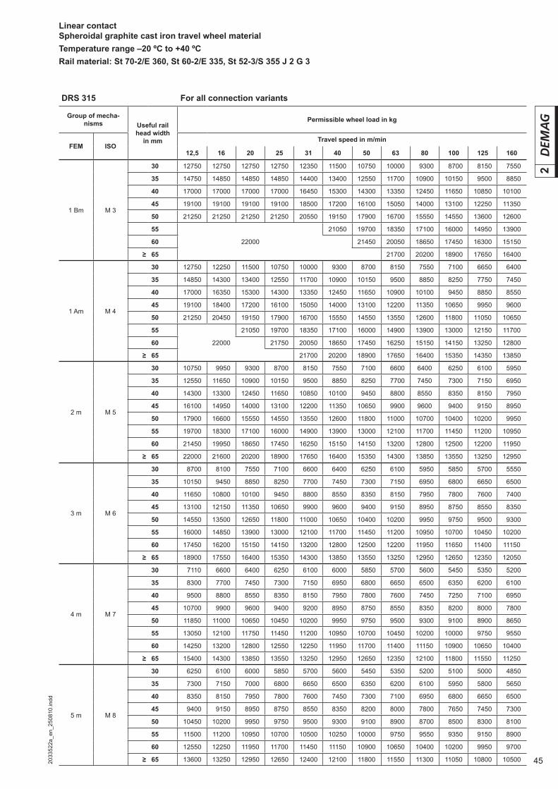
DRS 315 For all connection variants
Group of mecha-nisms Useful rail
head width in mm
Permissible wheel load in kg
FEM ISOTravel speed in m/min
12,5 16 20 25 31 40 50 63 80 100 125 160
1 Bm M 3
30 12750 12750 12750 12750 12350 11500 10750 10000 09300 08700 08150 07550
35 14750 14850 14850 14850 14400 13400 12550 11700 10900 10150 09500 08850
40 17000 17000 17000 17000 16450 15300 14300 13350 12450 11650 10850 10100
45 19100 19100 19100 19100 18500 17200 16100 15050 14000 13100 12250 11350
50 21250 21250 21250 21250 20550 19150 17900 16700 15550 14550 13600 12600
55 21050 19700 18350 17100 16000 14950 13900
60 22000 21450 20050 18650 17450 16300 15150
≥ 65 21700 20200 18900 17650 16400
1 Am M 4
30 12750 12250 11500 10750 10000 09300 08700 08150 07550 07100 06650 06400
35 14850 14300 13400 12550 11700 10900 10150 09500 08850 08250 07750 07450
40 17000 16350 15300 14300 13350 12450 11650 10900 10100 09450 08850 08550
45 19100 18400 17200 16100 15050 14000 13100 12200 11350 10650 09950 09600
50 21250 20450 19150 17900 16700 15550 14550 13550 12600 11800 11050 10650
55 21050 19700 18350 17100 16000 14900 13900 13000 12150 11700
60 22000 21750 20050 18650 17450 16250 15150 14150 13250 12800
≥ 65 21700 20200 18900 17650 16400 15350 14350 13850
2 m M 5
30 10750 09950 09300 08700 08150 07550 07100 06600 6400 06250 06100 05950
35 12550 11650 10900 10150 09500 08850 08250 07700 7450 07300 07150 06950
40 14300 13300 12450 11650 10850 10100 09450 08800 8550 08350 08150 07950
45 16100 14950 14000 13100 12200 11350 10650 09900 9600 09400 09150 08950
50 17900 16600 15550 14550 13550 12600 11800 11000 10700 10400 10200 09950
55 19700 18300 17100 16000 14900 13900 13000 12100 11700 11450 11200 10950
60 21450 19950 18650 17450 16250 15150 14150 13200 12800 12500 12200 11950
≥ 65 22000 21600 20200 18900 17650 16400 15350 14300 13850 13550 13250 12950
3 m M 6
30 08700 08100 07550 07100 06600 06400 06250 06100 05950 05850 05700 05550
35 10150 09450 08850 08250 07700 07450 07300 07150 06950 06800 06650 06500
40 11650 10800 10100 09450 08800 08550 08350 08150 07950 07800 07600 07400
45 13100 12150 11350 10650 09900 09600 09400 09150 08950 08750 08550 08350
50 14550 13500 12650 11800 11000 10650 10400 10200 09950 09750 09500 09300
55 16000 14850 13900 13000 12100 11700 11450 11200 10950 10700 10450 10200
60 17450 16200 15150 14150 13200 12800 12500 12200 11950 11650 11400 11150
≥ 65 18900 17550 16400 15350 14300 13850 13550 13250 12950 12650 12350 12050
4 m M 7
30 07110 06600 06400 06250 06100 06000 05850 05700 05600 05450 05350 05200
35 08300 07700 07450 07300 07150 06950 06800 06650 06500 06350 06200 06100
40 09500 08800 08550 08350 08150 07950 07800 07600 07450 07250 07100 06950
45 10700 09900 09600 09400 09200 08950 08750 08550 08350 08200 08000 07800
50 11850 11000 10650 10450 10200 09950 09750 09500 09300 09100 08900 08650
55 13050 12100 11750 11450 11200 10950 10700 10450 10200 10000 09750 09550
60 14250 13200 12800 12550 12250 11950 11700 11400 11150 10900 10650 10400
≥ 65 15400 14300 13850 13550 13250 12950 12650 12350 12100 11800 11550 11250
5 m M 8
30 06250 06100 06000 05850 05700 05600 05450 05350 05200 05100 05000 04850
35 07300 07150 07000 06800 06650 06500 06350 06200 06100 05950 05800 05650
40 08350 08150 07950 07800 07600 07450 07300 07100 06950 06800 06650 06500
45 09400 09150 08950 08750 08550 08350 08200 08000 07800 07650 07450 07300
50 10450 10200 09950 09750 09500 09300 09100 08900 08700 08500 08300 08100
55 11500 11200 10950 10700 10500 10250 10000 09750 09550 09350 09150 08900
60 12550 12250 11950 11700 11450 11150 10900 10650 10400 10200 09950 09700
≥ 65 13600 13250 12950 12650 12400 12100 11800 11550 11300 11050 10800 10500
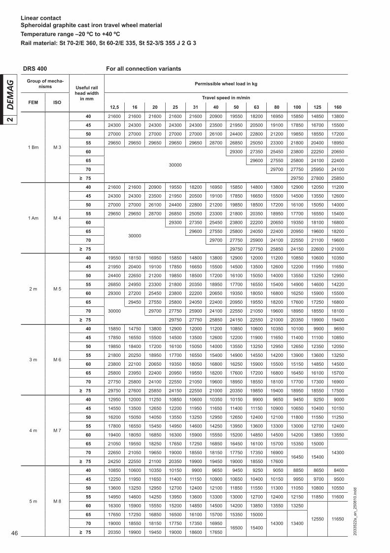
46 2033
522a
_en_
2508
10.in
dd
2Linear contactSpheroidal graphite cast iron travel wheel materialTemperature range –20 ºC to +40 ºCRail material: St 70-2/E 360, St 60-2/E 335, St 52-3/S 355 J 2 G 3
DRS 400 For all connection variants
Group of mecha-nisms Useful rail
head width in mm
Permissible wheel load in kg
FEM ISOTravel speed in m/min
12,5 16 20 25 31 40 50 63 80 100 125 160
1 Bm M 3
40 21600 21600 21600 21600 21600 20900 19550 18200 16950 15850 14850 13800
45 24300 24300 24300 24300 24300 23500 21950 20500 19100 17850 16700 15500
50 27000 27000 27000 27000 27000 26100 24400 22800 21200 19850 18550 17200
55 29650 29650 29650 29650 29650 28700 26850 25050 23300 21800 20400 18950
60 29300 27350 25450 23800 22250 20650
6530000
29600 27550 25800 24100 22400
70 29700 27750 25950 24100
≥ 75 29750 27800 25850
1 Am M 4
40 21600 21600 20900 19550 18200 16950 15850 14800 13800 12900 12050 11200
45 24300 24300 23500 21950 20500 19100 17850 16650 15500 14500 13550 12600
50 27000 27000 26100 24400 22800 21200 19850 18500 17200 16100 15050 14000
55 29650 29650 28700 26850 25050 23300 21800 20350 18950 17700 16550 15400
60 29300 27350 25450 23800 22200 20650 19350 18100 16800
6530000
29600 27550 25800 24050 22400 20950 19600 18200
70 29700 27750 25900 24100 22550 21100 19600
≥ 75 29750 27750 25850 24150 22600 21000
2 m M 5
40 19550 18150 16950 15850 14800 13800 12900 12000 11200 10850 10600 10350
45 21950 20400 19100 17850 16650 15500 14500 13500 12600 12200 11950 11650
50 24400 22650 21200 19850 18500 17200 16100 15050 14000 13550 13250 12950
55 26850 24950 23300 21800 20350 18950 17700 16550 15400 14900 14600 14220
60 29300 27200 25450 23800 22200 20650 19350 18050 16800 16250 15900 15500
65 29450 27550 25800 24050 22400 20950 19550 18200 17600 17250 16800
70 30000 29700 27750 25900 24100 22550 21050 19600 18950 18550 18100
≥ 75 29750 27750 25850 24150 22550 21000 20350 19900 19400
3 m M 6
40 15850 14750 13800 12900 12000 11200 10850 10600 10350 10100 09900 09650
45 17850 16550 15500 14500 13500 12600 12200 11900 11650 11400 11100 10850
50 19850 18400 17200 16100 15050 14000 13550 13250 12950 12650 12350 12050
55 21800 20250 18950 17700 16550 15400 14900 14550 14200 13900 13600 13250
60 23800 22100 20650 19350 18050 16800 16250 15900 15500 15150 14850 14500
65 25800 23950 22400 20950 19550 18200 17600 17200 16800 16450 16100 15700
70 27750 25800 24100 22550 21050 19600 18950 18550 18100 17700 17300 16900
≥ 75 29750 27600 25850 24150 22550 21000 20350 19850 19400 18950 18550 17500
4 m M 7
40 12950 12000 11250 10850 10600 10350 10150 09900 09650 09450 09250 09000
45 14550 13500 12650 12200 11950 11650 11400 11150 10900 10650 10400 10150
50 16200 15050 14050 13550 13250 12950 12650 12400 12100 11800 11550 11250
55 17800 16550 15450 14950 14600 14250 13950 13600 13300 13000 12700 12400
60 19400 18050 16850 16300 15900 15550 15200 14850 14500 14200 13850 13550
65 21050 19550 18250 17650 17250 16850 16450 16100 15700 15350 15000
1430070 22650 21050 19650 19000 18550 18150 17750 17350 1690016450 15400
≥ 75 24250 22550 21100 20350 19900 19450 19000 18550 17600
5 m M 8
40 10850 10600 10350 10150 09900 09650 09450 09250 09050 08850 08650 08400
45 12250 11950 11650 11400 11150 10900 10650 10400 10150 09950 09700 09500
50 13600 13250 12950 12700 12400 12100 11850 11550 11300 11050 10800 10550
55 14950 14600 14250 13950 13600 13300 13000 12700 12400 12150 11850 11600
60 16300 15900 15550 15200 14850 14500 14200 13850 13550 13250
12550 1165065 17650 17250 16850 16500 16100 15700 15350 15000
14300 1340070 19000 18550 18150 17750 17350 1695016500 15400
≥ 75 20350 19900 19450 19000 18600 17650
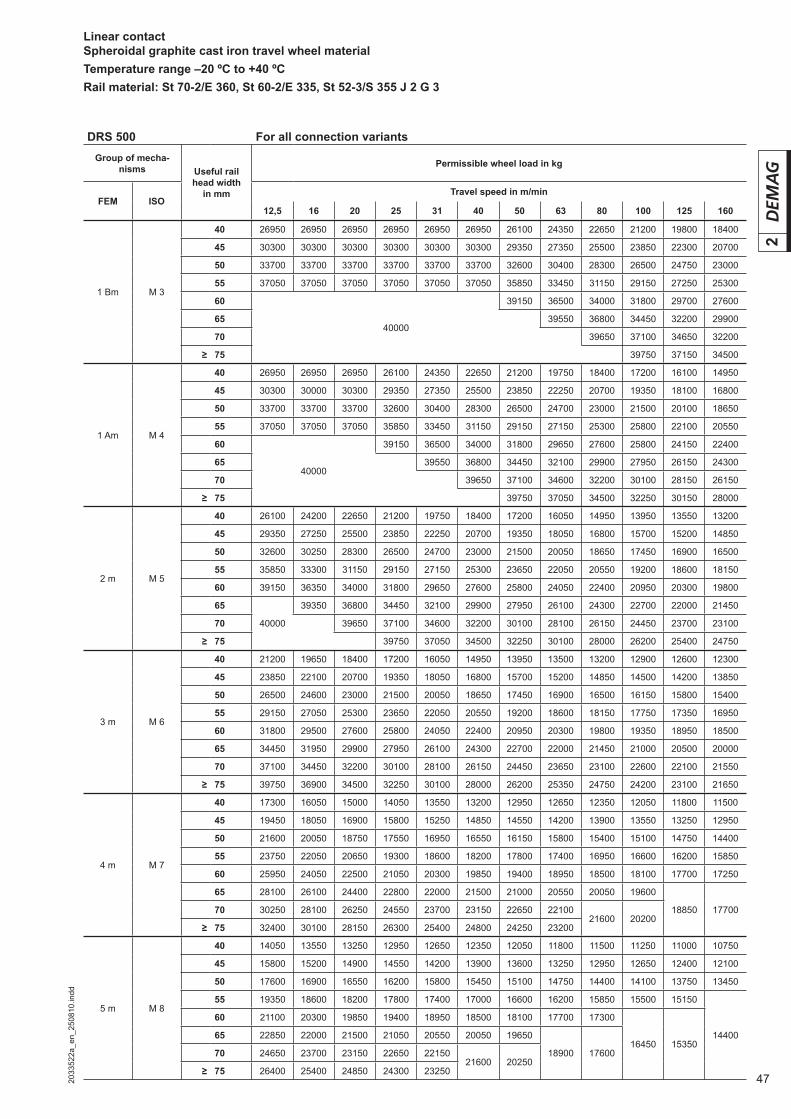
472033
522a
_en_
2508
10.in
dd
2
Linear contactSpheroidal graphite cast iron travel wheel materialTemperature range –20 ºC to +40 ºCRail material: St 70-2/E 360, St 60-2/E 335, St 52-3/S 355 J 2 G 3
DRS 500 For all connection variantsGroup of mecha-
nisms Useful rail head width
in mm
Permissible wheel load in kg
FEM ISOTravel speed in m/min
12,5 16 20 25 31 40 50 63 80 100 125 160
1 Bm M 3
40 26950 26950 26950 26950 26950 26950 26100 24350 22650 21200 19800 18400
45 30300 30300 30300 30300 30300 30300 29350 27350 25500 23850 22300 20700
50 33700 33700 33700 33700 33700 33700 32600 30400 28300 26500 24750 23000
55 37050 37050 37050 37050 37050 37050 35850 33450 31150 29150 27250 25300
60 39150 36500 34000 31800 29700 27600
6540000
39550 36800 34450 32200 29900
70 39650 37100 34650 32200
≥ 75 39750 37150 34500
1 Am M 4
40 26950 26950 26950 26100 24350 22650 21200 19750 18400 17200 16100 14950
45 30300 30000 30300 29350 27350 25500 23850 22250 20700 19350 18100 16800
50 33700 33700 33700 32600 30400 28300 26500 24700 23000 21500 20100 18650
55 37050 37050 37050 35850 33450 31150 29150 27150 25300 25800 22100 20550
60 39150 36500 34000 31800 29650 27600 25800 24150 22400
6540000
39550 36800 34450 32100 29900 27950 26150 24300
70 39650 37100 34600 32200 30100 28150 26150
≥ 75 39750 37050 34500 32250 30150 28000
2 m M 5
40 26100 24200 22650 21200 19750 18400 17200 16050 14950 13950 13550 13200
45 29350 27250 25500 23850 22250 20700 19350 18050 16800 15700 15200 14850
50 32600 30250 28300 26500 24700 23000 21500 20050 18650 17450 16900 16500
55 35850 33300 31150 29150 27150 25300 23650 22050 20550 19200 18600 18150
60 39150 36350 34000 31800 29650 27600 25800 24050 22400 20950 20300 19800
65 39350 36800 34450 32100 29900 27950 26100 24300 22700 22000 21450
70 40000 39650 37100 34600 32200 30100 28100 26150 24450 23700 23100
≥ 75 39750 37050 34500 32250 30100 28000 26200 25400 24750
3 m M 6
40 21200 19650 18400 17200 16050 14950 13950 13500 13200 12900 12600 12300
45 23850 22100 20700 19350 18050 16800 15700 15200 14850 14500 14200 13850
50 26500 24600 23000 21500 20050 18650 17450 16900 16500 16150 15800 15400
55 29150 27050 25300 23650 22050 20550 19200 18600 18150 17750 17350 16950
60 31800 29500 27600 25800 24050 22400 20950 20300 19800 19350 18950 18500
65 34450 31950 29900 27950 26100 24300 22700 22000 21450 21000 20500 20000
70 37100 34450 32200 30100 28100 26150 24450 23650 23100 22600 22100 21550
≥ 75 39750 36900 34500 32250 30100 28000 26200 25350 24750 24200 23100 21650
4 m M 7
40 17300 16050 15000 14050 13550 13200 12950 12650 12350 12050 11800 11500
45 19450 18050 16900 15800 15250 14850 14550 14200 13900 13550 13250 12950
50 21600 20050 18750 17550 16950 16550 16150 15800 15400 15100 14750 14400
55 23750 22050 20650 19300 18600 18200 17800 17400 16950 16600 16200 15850
60 25950 24050 22500 21050 20300 19850 19400 18950 18500 18100 17700 17250
65 28100 26100 24400 22800 22000 21500 21000 20550 20050 19600
18850 1770070 30250 28100 26250 24550 23700 23150 22650 2210021600 20200
≥ 75 32400 30100 28150 26300 25400 24800 24250 23200
5 m M 8
40 14050 13550 13250 12950 12650 12350 12050 11800 11500 11250 11000 10750
45 15800 15200 14900 14550 14200 13900 13600 13250 12950 12650 12400 12100
50 17600 16900 16550 16200 15800 15450 15100 14750 14400 14100 13750 13450
55 19350 18600 18200 17800 17400 17000 16600 16200 15850 15500 15150
14400
60 21100 20300 19850 19400 18950 18500 18100 17700 17300
16450 1535065 22850 22000 21500 21050 20550 20050 19650
18900 1760070 24650 23700 23150 22650 2215021600 20250
≥ 75 26400 25400 24850 24300 23250
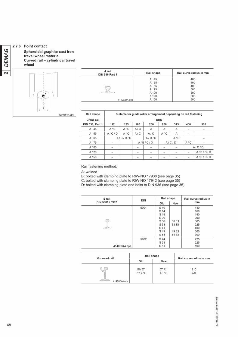
48 2033
522b
_en_
2508
10.in
dd
2
S railDIN 5901 / 5902 DIN
Rail shape Rail curve radius in mmOld New
5901 S 10S 14S 18S 20S 30S 33S 41S 49S 54
30 E133 E1
49 E154 E3
140160180200305225400300300
41409344.eps
5902 S 24S 33S 41
225225400
A railDIN 536 Part 1 Rail shape Rail curve radius in mm
41409244.eps
A 045A 055A 065A 075A 100A 120A 150
400400400500500600800
2.7.6 Point contactSpheroidal graphite cast iron travel wheel materialCurved rail – cylindrical travel wheel
Rail fastening method:A: weldedB: bolted with clamping plate to RIW-NO 17938 (see page 35)C: bolted with clamping plate to RIW-NO 17942 (see page 35)D: bolted with clamping plate and bolts to DIN 936 (see page 35)
Rail shape Suitable for guide roller arrangement depending on rail fastening
Crane rail DRSDIN 536, Part 1 112 125 160 200 250 315 400 500
A 045 A / C A / C A / C A A A – –A 055 A / C / D A / C A / C A / C A / C A – –A 065 A / B / C / D A / C / D A / C –A 075 – A / B / C / D A / C / D A / C –
A 100 – – – – – A / C / D
A 120 – – – – – – A / B / C / D
A 150 – – – – – – A / B / C / D
42098544.eps
Grooved railRail shape
Rail curve radius in mmOld New
41408844.eps
Ph 37Ph 37a
57 Ri167 Ri1
210225

492033
522b
_en_
2508
10.in
dd
2
Reduction factor fRS for curve radius
Point contactConvex/curved rail – cylindrical travel wheelFlat rail – concave travel wheelSpheroidal graphite cast iron travel wheel material
Permissible wheel loads Rperm (rail) are used in section 5.3 for determining the maximum permissible wheel load for a wheel block.
fk = Reduction factor for temperature, see section 1.11
Important: Use the smallest calculated value Rperm (temperature) or Rperm (rail) for further calculation.
Note:Cylindrical travel wheels on curved rails are standard, concave special travel wheels on fl at rails are special cases.
Curve radius r2 DRS wheel block size
in mm 112 125 160 200 250 315 400 500
< 140 - - - - - - -
≥ 140 0,68 0,53 0,42 0,37 0,29 0,26 0,24 0,22
≥ 160 0,76 0,59 0,47 0,4 0,33 0,30 0,28 0,26
≥ 180 0,84 0,66 0,52 0,46 0,37 0,34 0,31 0,29
≥ 210 0,95 0,74 0,59 0,53 0,42 0,39 0,36 0,34
≥ 225 0,79 0,63 0,56 0,45 0,42 0,39 0,37
≥ 300 0,99 0,80 0,71 0,58 0,54 0,52 0,49
≥ 305 0,81 0,72 0,59 0,55 0,52 0,5
≥ 400 0,90 0,73 0,70 0,67 0,64
≥ 500 0,88 0,84 0,81 0,78
≥ 600 0,97 0,95 0,92
≥ 625 0,98 0,95
≥ 645 1 0,98
≥ 665
≥ 790
≥ 1005
≥ 1260
Rperm (rail) = Permissible wheel load for point contact on steel railsRperm (point ) = Permissible wheel load for point contact (table value, see pages 52/53)fSt = Reduction factor for rail material for point contact, see section 1.11fRS = Reduction factor for the curve radius for point contact, see the fol-
lowing table
Rperm (rail) = Rperm (point) · fSt · fRS
42098544.eps
Rperm (temperature) = Rperm (linear) · fk

50 2033
522b
_en_
2508
10.in
dd
2
Travel wheel tread is determined as 1,1 · RS. Requirement: The permissible hori-zontal force (see section 1.10) must not exceed 20% of the actual wheel load.
Round rail – travel wheel with concave tread
Point contact – spheroidal graphite cast iron travel wheel material
41409044.eps
Angular rail – travel wheel for V rail
Rperm (rail) = Permissible wheel load for point contact on steel railsRperm (point ) = Permissible wheel load for point contact (table value, see pages 52/53)fSt = Reduction factor for rail material for point contact, see section 1.11
41408944.eps
Rperm (rail) = Permissible wheel load for point contact for travel wheels with concave tread on steel rails
Rperm (point) = Permissible wheel load for point contact for travel wheels with concave tread (table value, see pages 52/53)
fSt = Reduction factor for rail material for point contact, see section 1.11fRS = Reduction factor for the curve radius for point contact for travel
wheels with concave tread, see page 51
Rail shapeSemi-round or round profi le
Permissible wheel loads Rperm (rail) are used in section 5.3 for determining the maximum permissible wheel load for a wheel block.
fk = Reduction factor for temperature, see section 1.11
Important: Use the smallest calculated value Rperm (temperature) or Rperm (rail) for further calculation.
Permissible wheel loads Rperm (rail) are used in section 5.3 for determining the maximum permissible wheel load for a wheel block.
fk = Feduction factor for temperature, see section 1.11
Important: Use the smallest calculated value Rperm (temperature) or Rperm (rail) for further calculation.
Rail shapeRight angle
Rperm (rail) = Rperm (point) · fSt · 0,7
Rperm (rail) = Rperm (point) · fSt · fRS
Rperm (temperature) = Rperm (linear) · fk
Rperm (temperature) = Rperm (linear) · fk
Point contact – spheroidal graphite cast iron travel wheel material
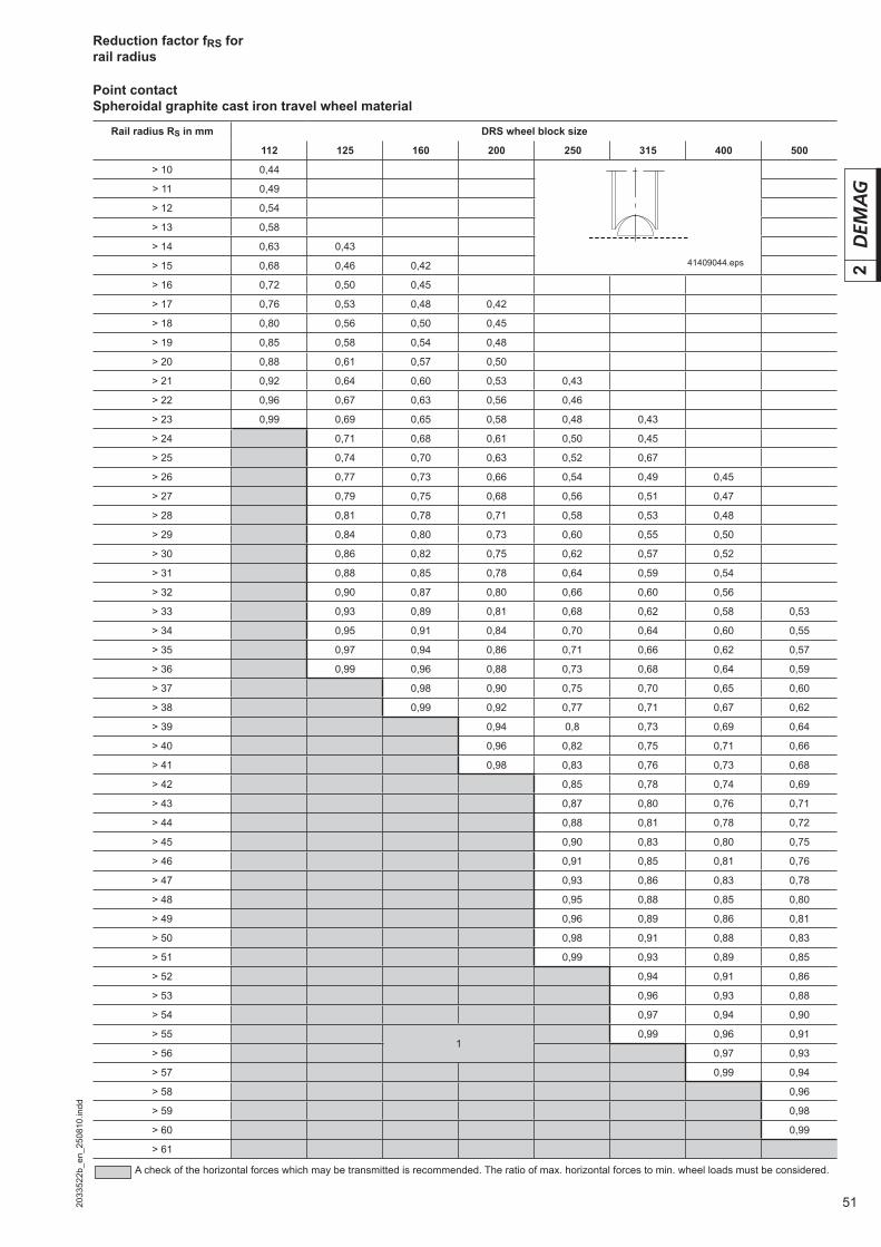
512033
522b
_en_
2508
10.in
dd
2
Reduction factor fRS for rail radius
A check of the horizontal forces which may be transmitted is recommended. The ratio of max. horizontal forces to min. wheel loads must be considered.
Point contactSpheroidal graphite cast iron travel wheel material
Rail radius RS in mm DRS wheel block size
112 125 160 200 250 315 400 500
> 10 0,44
> 11 0,49
> 12 0,54
> 13 0,58
> 14 0,63 0,43
> 15 0,68 0,46 0,42
> 16 0,72 0,50 0,45
> 17 0,76 0,53 0,48 0,42
> 18 0,80 0,56 0,50 0,45
> 19 0,85 0,58 0,54 0,48
> 20 0,88 0,61 0,57 0,50
> 21 0,92 0,64 0,60 0,53 0,43
> 22 0,96 0,67 0,63 0,56 0,46
> 23 0,99 0,69 0,65 0,58 0,48 0,43
> 24 0,71 0,68 0,61 0,50 0,45
> 25 0,74 0,70 0,63 0,52 0,67
> 26 0,77 0,73 0,66 0,54 0,49 0,45
> 27 0,79 0,75 0,68 0,56 0,51 0,47
> 28 0,81 0,78 0,71 0,58 0,53 0,48
> 29 0,84 0,80 0,73 0,60 0,55 0,50
> 30 0,86 0,82 0,75 0,62 0,57 0,52
> 31 0,88 0,85 0,78 0,64 0,59 0,54
> 32 0,90 0,87 0,80 0,66 0,60 0,56
> 33 0,93 0,89 0,81 0,68 0,62 0,58 0,53
> 34 0,95 0,91 0,84 0,70 0,64 0,60 0,55
> 35 0,97 0,94 0,86 0,71 0,66 0,62 0,57
> 36 0,99 0,96 0,88 0,73 0,68 0,64 0,59
> 37 0,98 0,90 0,75 0,70 0,65 0,60
> 38 0,99 0,92 0,77 0,71 0,67 0,62
> 39 0,94 0,8 0,73 0,69 0,64
> 40 0,96 0,82 0,75 0,71 0,66
> 41 0,98 0,83 0,76 0,73 0,68
> 42 0,85 0,78 0,74 0,69
> 43 0,87 0,80 0,76 0,71
> 44 0,88 0,81 0,78 0,72
> 45 0,90 0,83 0,80 0,75
> 46 0,91 0,85 0,81 0,76
> 47 0,93 0,86 0,83 0,78
> 48 0,95 0,88 0,85 0,80
> 49 0,96 0,89 0,86 0,81
> 50 0,98 0,91 0,88 0,83
> 51 0,99 0,93 0,89 0,85
> 52 0,94 0,91 0,86
> 53 0,96 0,93 0,88
> 54 0,97 0,94 0,90
> 551
0,99 0,96 0,91
> 56 0,97 0,93
> 57 0,99 0,94
> 58 0,96
> 59 0,98
> 60 0,99
> 61
41409044.eps
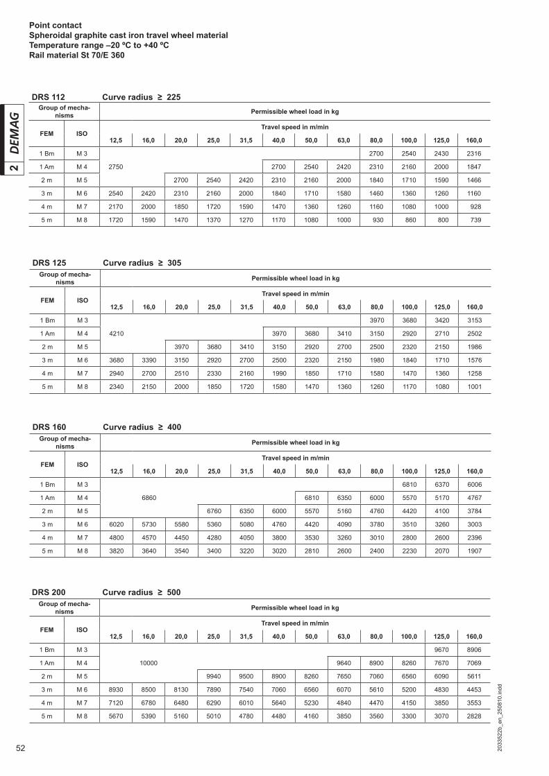
52 2033
522b
_en_
2508
10.in
dd
2Point contactSpheroidal graphite cast iron travel wheel materialTemperature range –20 ºC to +40 ºCRail material St 70/E 360
DRS 112 Curve radius ≥ 225Group of mecha-
nisms Permissible wheel load in kg
FEM ISOTravel speed in m/min
12,5 16,0 20,0 25,0 31,5 40,0 50,0 63,0 80,0 100,0 125,0 160,0
1 Bm M 3 2700 2540 2430 2316
1 Am M 4 2750 2700 2540 2420 2310 2160 2000 1847
2 m M 5 2700 2540 2420 2310 2160 2000 1840 1710 1590 1466
3 m M 6 2540 2420 2310 2160 2000 1840 1710 1580 1460 1360 1260 1160
4 m M 7 2170 2000 1850 1720 1590 1470 1360 1260 1160 1080 1000 0928
5 m M 8 1720 1590 1470 1370 1270 1170 1080 1000 0930 0860 0800 0739
DRS 125 Curve radius ≥ 305Group of mecha-
nisms Permissible wheel load in kg
FEM ISOTravel speed in m/min
12,5 16,0 20,0 25,0 31,5 40,0 50,0 63,0 80,0 100,0 125,0 160,0
1 Bm M 3 3970 3680 3420 3153
1 Am M 4 4210 3970 3680 3410 3150 2920 2710 2502
2 m M 5 3970 3680 3410 3150 2920 2700 2500 2320 2150 1986
3 m M 6 3680 3390 3150 2920 2700 2500 2320 2150 1980 1840 1710 1576
4 m M 7 2940 2700 2510 2330 2160 1990 1850 1710 1580 1470 1360 1258
5 m M 8 2340 2150 2000 1850 1720 1580 1470 1360 1260 1170 1080 1001
DRS 160 Curve radius ≥ 400Group of mecha-
nisms Permissible wheel load in kg
FEM ISOTravel speed in m/min
12,5 16,0 20,0 25,0 31,5 40,0 50,0 63,0 80,0 100,0 125,0 160,0
1 Bm M 3 6810 6370 6006
1 Am M 4 6860 6810 6350 6000 5570 5170 4767
2 m M 5 6760 6350 6000 5570 5160 4760 4420 4100 3784
3 m M 6 6020 5730 5580 5360 5080 4760 4420 4090 3780 3510 3260 3003
4 m M 7 4800 4570 4450 4280 4050 3800 3530 3260 3010 2800 2600 2396
5 m M 8 3820 3640 3540 3400 3220 3020 2810 2600 2400 2230 2070 1907
DRS 200 Curve radius ≥ 500Group of mecha-
nisms Permissible wheel load in kg
FEM ISOTravel speed in m/min
12,5 16,0 20,0 25,0 31,5 40,0 50,0 63,0 80,0 100,0 125,0 160,0
1 Bm M 3 9670 8906
1 Am M 4 10000 9640 8900 8260 7670 7069
2 m M 5 9940 9500 8900 8260 7650 7060 6560 6090 5611
3 m M 6 8930 8500 8130 7890 7540 7060 6560 6070 5610 5200 4830 4453
4 m M 7 7120 6780 6480 6290 6010 5640 5230 4840 4470 4150 3850 3553
5 m M 8 5670 5390 5160 5010 4780 4480 4160 3850 3560 3300 3070 2828

532033
522b
_en_
2508
10.in
dd
2
Point contactSpheroidal graphite cast iron travel wheel materialTemperature range –20 ºC to +40 ºCRail material St 70/E 360
DRS 250 Curve radius ≥ 600Group of mecha-
nisms Permissible wheel load in kg
FEM ISOTravel speed in m/min
12,5 16,0 20,0 25,0 31,5 40,0 50,0 63,0 80,0 100,0 125,0 160,0
1 Bm M 3 15020 14050
1 Am M 4 16000 15020 14060 13080 12200 11400
2 m M 5 15020 14060 13080 12200 11420 10620 09910 9250
3 m M 6 15020 14140 13180 12200 11420 10620 09910 09380 08630 08100 7550
4 m M 7 13080 12200 11420 10620 09910 09280 08630 08100 07580 07050 06600 6150
5 m M 8 10620 09910 09280 08630 08100 07580 07070 06600 06170 05740 05360 5000
DRS 315 Curve radius ≥ 625Group of mecha-
nisms Permissible wheel load in kg
FEM ISOTravel speed in m/min
12,5 16,0 20,0 25,0 31,5 40,0 50,0 63,0 80,0 100,0 125,0 160,0
1 Bm M 3
1 Am M 4 22000 21050 19900
2 m M 5 21000 19900 19050 18200 17300
3 m M 6 21000 19900 19050 18200 17350 16600 15850 15050
4 m M 7 21000 20000 19100 18250 17400 16650 15900 15150 14500 13750 12850
5 m M 8 19150 18200 17400 16650 15900 15150 14500 13800 12900 12000 11200 10450
DRS 500 Curve radius ≥ 665Group of mecha-
nisms Permissible wheel load in kg
FEM ISOTravel speed in m/min
12,5 16,0 20,0 25,0 31,5 40,0 50,0 63,0 80,0 100,0 125,0 160,0
1 Bm M 3
1 Am M 4 40000 37500 35000 32800
2 m M 5 37500 35000 32600 30450 28450 26650
3 m M 6 37750 35000 32600 30500 28450 26450 24750 23100 21650
4 m M 7 37700 35050 32800 30850 28600 26600 24900 23200 21600 20200 18850 17700
5 m M 8 30700 28550 26700 25100 23250 21650 20250 18900 17600 16450 15350 14400
DRS 400 Curve radius ≥ 645Group of mecha-
nisms Permissible wheel load in kg
FEM ISOTravel speed in m/min
12,5 16,0 20,0 25,0 31,5 40,0 50,0 63,0 80,0 100,0 125,0 160,0
1 Bm M 3
1 Am M 4 30000 28550 26500
2 m M 5 28450 26500 24800 23200 21500
3 m M 6 28450 26500 24800 23150 21550 20150 18850 17450
4 m M 7 28500 26650 24950 23250 21650 20250 18900 17600 16450 15400 14250
5 m M 8 24950 23200 21700 20300 18950 17650 16500 15400 14300 13400 12550 11600
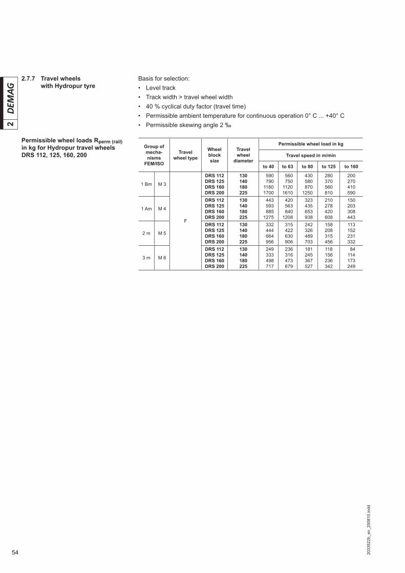
54 2033
522b
_en_
2508
10.in
dd
2
Permissible wheel loads Rperm (rail) in kg for Hydropur travel wheels DRS 112, 125, 160, 200
Basis for selection:• Level track• Track width > travel wheel width• 40 % cyclical duty factor (travel time)• Permissible ambient temperature for continuous operation 0° C ... +40° C• Permissible skewing angle 2 ‰
2.7.7 Travel wheels with Hydropur tyre
Group of mecha-nisms
FEM/ISO
Travel wheel type
Wheel block size
Travel wheel
diameter
Permissible wheel load in kg
Travel speed in m/min
to 40 to 63 to 80 to 125 to 160
1 Bm M 3
F
DRS 112DRS 125DRS 160DRS 200
130140180225
0590079011801700
0560075011201610
0430058008701250
280370560810
200270410590
1 Am M 4
DRS 112DRS 125DRS 160DRS 200
130140180225
0443059308851275
0420056308401208
0323043506530938
210278420608
150203308443
2 m M 5
DRS 112DRS 125DRS 160DRS 200
130140180225
0332044406640956
0315042206300906
0242032604890703
158208315456
113152231332
3 m M 6
DRS 112DRS 125DRS 160DRS 200
130140180225
0249033304980717
0236031604730679
0181024503670527
118156236342
084114173249
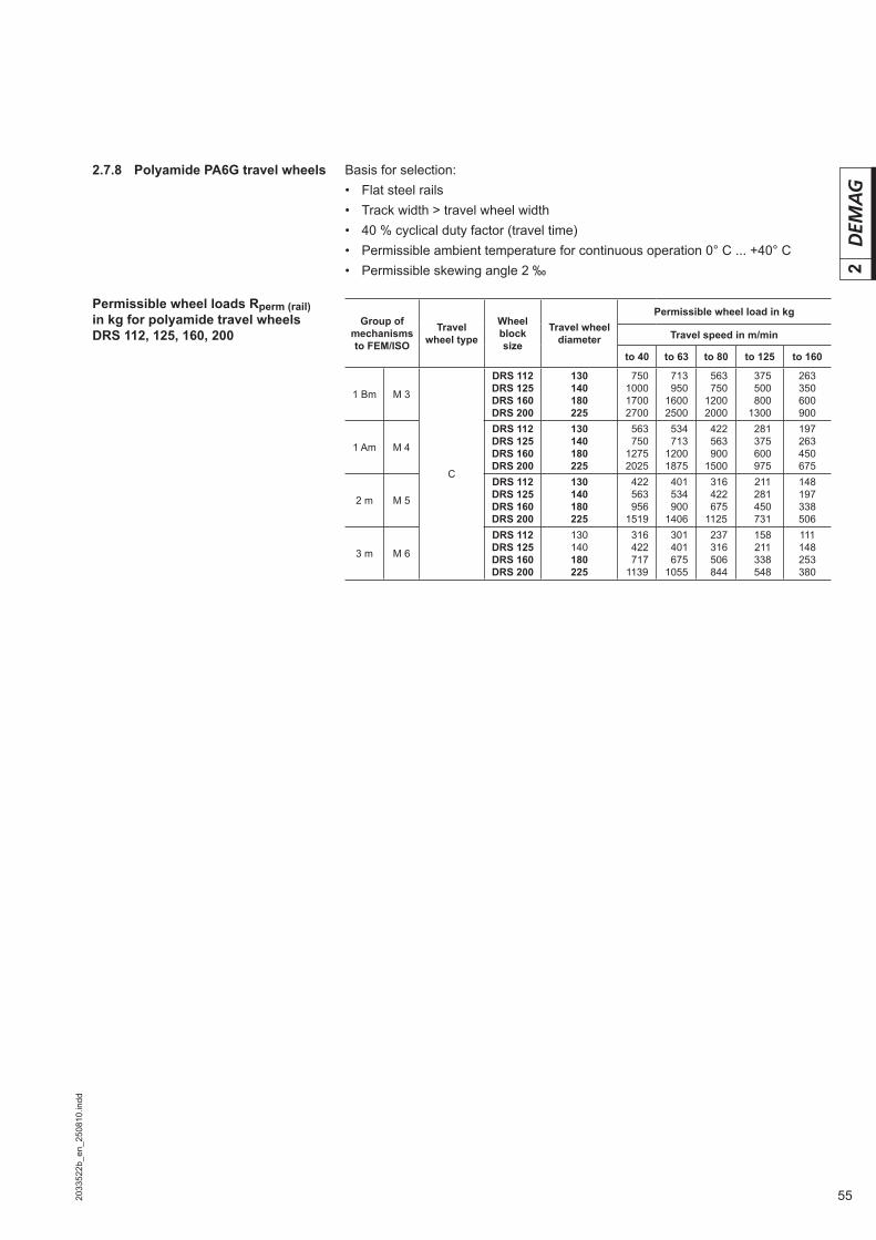
552033
522b
_en_
2508
10.in
dd
2
Permissible wheel loads Rperm (rail) in kg for polyamide travel wheels DRS 112, 125, 160, 200
Basis for selection:• Flat steel rails• Track width > travel wheel width• 40 % cyclical duty factor (travel time)• Permissible ambient temperature for continuous operation 0° C ... +40° C• Permissible skewing angle 2 ‰
2.7.8 Polyamide PA6G travel wheels
Group of mechanisms to FEM/ISO
Travel wheel type
Wheel block size
Travel wheel diameter
Permissible wheel load in kg
Travel speed in m/min
to 40 to 63 to 80 to 125 to 160
1 Bm M 3
C
DRS 112DRS 125DRS 160DRS 200
130140180225
0750100017002700
0713 095016002500
0563075012002000
0375050008001300
263350600900
1 Am M 4
DRS 112DRS 125DRS 160DRS 200
130140180225
0563075012752025
0534071312001875
0422056309001500
0281037506000975
197263450675
2 m M 5
DRS 112DRS 125DRS 160DRS 200
130140180225
0422056309561519
0401053409001406
0316042206751125
0211028104500731
148197338506
3 m M 6
DRS 112DRS 125DRS 160DRS 200
130140180225
0316042207171139
0301040106751055
0237031605060844
0158021103380548
111148253380

56
3
2033
523a
_en_
2508
10.in
ddc4
c4
42064744.eps
3 Demag DRS wheel block system Data and dimensions
3.1 Data and dimensions DRS 112 – 200
Travel wheel types
DRS 112/125M12x12 deepDRS 160M16x14 deep(Only if wheel block is prepared for fi tting guide rollers)
MA NA
B CA
E FD
A
DRS 112 – 160 DRS 200
DRS 200M16x14 deep(Only if wheel block is prepared for fi tting guide rollers)
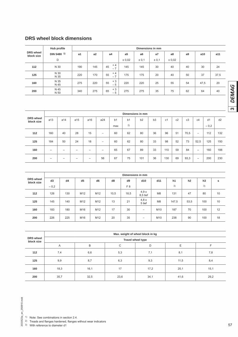
57
3
2033
523a
_en_
2508
10.in
dd
DRS wheel block dimensions
DRS wheel block size
Dimensions in mm
a13 a14 a15 a16 a24 b1 b1 b2 b3 c1 c2 c3 c4 d1 d2
max 2) – 0,2
112 160 40 28 15 – 60 62 80 36 96 51 70,5 – 112 132
125 184 50 24 18 – 60 62 80 33 98 52 73 52,5 125 150
160 – – – – – 65 67 89 33 110 59 84 – 160 188
200 – – – – 56 67 75 101 36 130 69 93,3 – 200 230
DRS wheel block size
Max. weight of wheel block in kg
Travel wheel type
A B C D E F
112 7,4 6,6 5,3 7,1 8,1 7,8
125 9,9 8,7 6,3 9,3 11,5 8,4
160 18,3 16,1 17 17,2 20,1 15,1
200 35,7 32,5 23,6 34,1 41,6 29,2
DRS wheel block size
Hub profi le Dimensions in mm
DIN 5480 1) a1 a2 a4 a5 a6 a7 a8 a9 a10 a11
D ± 0,02 ± 0,1 ± 0,1 ± 0,02 1
112 N 30 190 145 45 + 4– 7 145 145 30 40 40 30 24
125 N 30N 35 220 170 55 + 4
– 7 175 175 20 40 50 37 37,5
160 N 35N 45 275 220 55 + 3
– 5 220 220 25 55 54 47,5 20
200 N 45N 50 340 275 65 + 3
– 5 275 275 35 75 62 64 40
DRS wheel block size
Dimensions in mm
d3 d4 d5 d6 d8 d9 d10 d11 h1 h2 h3 s
– 0,2 F 8 3) 3)
112 126 130 M12 M12 10,5 18,5 4,9 x8,5 tief M8 131 47 80 10
125 145 140 M12 M12 13 21 4,8 x5 tief M8 147,5 53,5 100 10
160 183 180 M16 M12 17 30 – M10 187 70 100 12
200 226 225 M16 M12 20 35 – M10 238 90 100 18
1) Note: See combinations in section 2.4.2) Treads and fl anges hardened, fl anges without wear indicators3) With reference to diameter d1
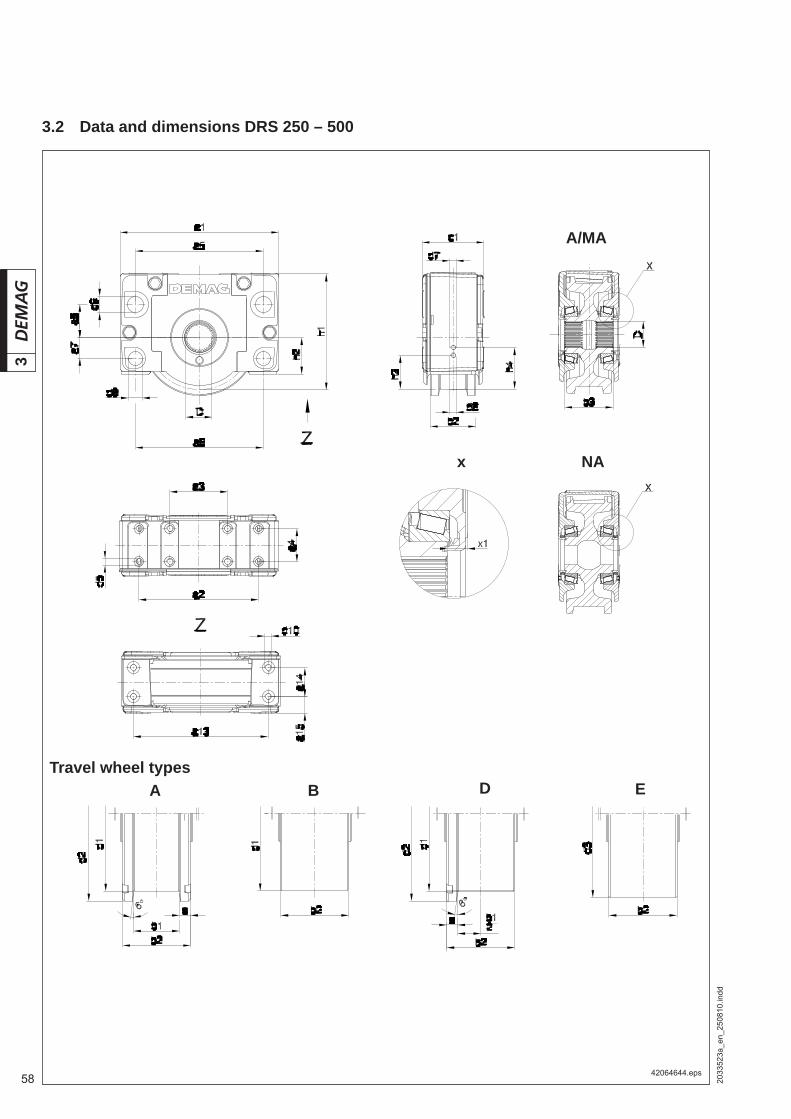
58
3
2033
523a
_en_
2508
10.in
dd
42064644.eps
x
3.2 Data and dimensions DRS 250 – 500
A/MA
NA
Travel wheel types B DA E

59
3
2033
523a
_en_
2508
10.in
dd
DRS wheel block size
Dimensions in mm
a15 b1 b1 b2 b3 c1 d1 d2 d3 d5 d6 d7 d8
± 0,2 max 2) – 0,2 – 0,2
250 40 77 80 110 117,5 150 250 282 270 8 x M16 M12 – 34 F8
315 50 90 96 130 147 180 315 350 340 8 x M16 M12 M20 40 F8
400 55 110 - 155 172 210 400 440 440 8 x M20 M12 M20 31 H13
500 65 110 - 170 195 240 500 545 545 8 x M20 M12 M20 31 H13
DRS wheel block size
Dimensions in mm Max. weight of wheel block in kg
d9 d10 h1 h2 h3 h4 s x1 Travel wheel type
F 8 3) 3) 3) min A B D E
250 40 M16 x20 deep 281 89 100 – 17,5 16,3 63 57 58 65
315 50 M20 x20 deep 349,5 114 100 130 20 16,5 121 115 118 127
400 65 M24 x20 deep 440 144 100 130 22,5 19 214 196 205 232
500 70 M24 x25 deep 566 183 100 130 30 22,5 373 351 362 397
DRS wheel block size
Hub profi le Dimensions in mm
DIN 5480 1) a1 a2 a3 a4 a5 a6 a7 a8 a13 a14
D ± 0,2 ± 0,2 ± 0,2 ± 0,04 ± 0,04 ± 0,02 ± 0,02 ± 0,41 ± 0,21
250 N 50N 65 385 290 140 80 310 310 50 80 326 70
315 N 65N 75 470 360 180 100 370 370 70 80 405 80
400 N 75N 90 580 440 210 120 450 450 95 130 501 100
500 N90N110 700 620 480 125 580 580 110 160 600 110
1) Note: See combinations in section 2.4.2) Treads and fl anges hardened3) With reference to diameter d1
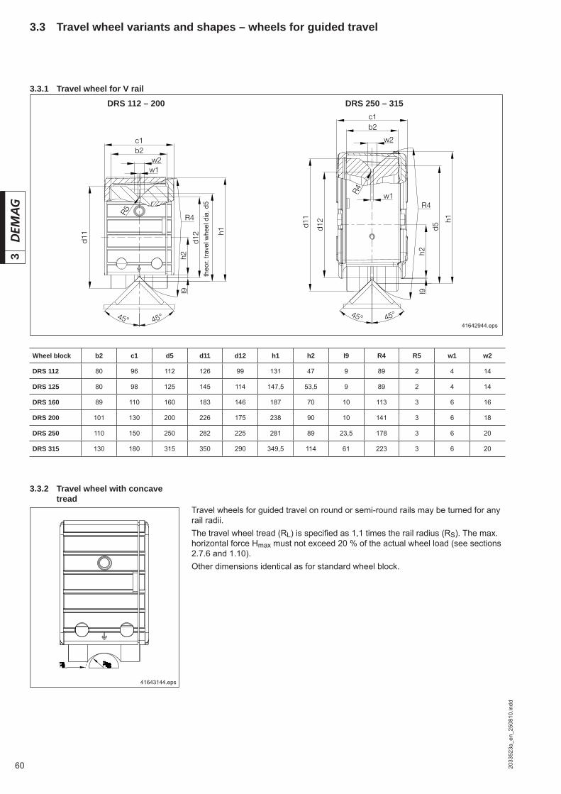
60
3
2033
523a
_en_
2508
10.in
dd
3.3.2 Travel wheel with concave tread
Travel wheels for guided travel on round or semi-round rails may be turned for any rail radii.The travel wheel tread (RL) is specifi ed as 1,1 times the rail radius (RS). The max. horizontal force Hmax must not exceed 20 % of the actual wheel load (see sections 2.7.6 and 1.10).Other dimensions identical as for standard wheel block.
41642944.eps
theo
r. tra
vel w
heel
dia
. d5
41643144.eps
3.3 Travel wheel variants and shapes – wheels for guided travel
3.3.1 Travel wheel for V rail
Wheel block b2 c1 d5 d11 d12 h1 h2 I9 R4 R5 w1 w2
DRS 112 80 96 112 126 99 131 47 9 89 2 4 14
DRS 125 80 98 125 145 114 147,5 53,5 9 89 2 4 14
DRS 160 89 110 160 183 146 187 70 10 113 3 6 16
DRS 200 101 130 200 226 175 238 90 10 141 3 6 18
DRS 250 110 150 250 282 225 281 89 23,5 178 3 6 20
DRS 315 130 180 315 350 290 349,5 114 61 223 3 6 20
DRS 112 – 200 DRS 250 – 315
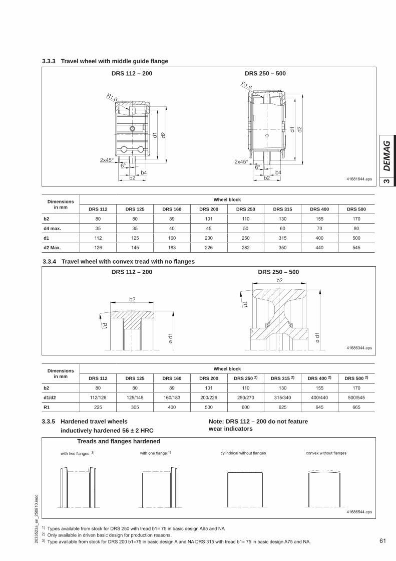
61
3
2033
523a
_en_
2508
10.in
dd
ø d1
R1
b2
ø d1
R1
b2
3.3.3 Travel wheel with middle guide fl ange
DRS 112 – 200 DRS 250 – 500
Dimensions in mm
Wheel block
DRS 112 DRS 125 DRS 160 DRS 200 DRS 250 DRS 315 DRS 400 DRS 500
b2 80 80 89 101 110 130 155 170
d4 max. 35 35 40 45 50 60 70 80
d1 112 125 160 200 250 315 400 500
d2 Max. 126 145 183 226 282 350 440 545
3.3.4 Travel wheel with convex tread with no fl anges
Dimensions in mm
Wheel block
DRS 112 DRS 125 DRS 160 DRS 200 DRS 250 2) DRS 315 2) DRS 400 2) DRS 500 2)
b2 80 80 89 101 110 130 155 170
d1/d2 112/126 125/145 160/183 200/226 250/270 315/340 400/440 500/545
R1 225 305 400 500 600 625 645 665
3.3.5 Hardened travel wheels inductively hardened 56 ± 2 HRC
Note: DRS 112 – 200 do not feature wear indicators
Treads and fl anges hardened
with two fl anges 3) with one fl ange 1) convex without fl angescylindrical without fl anges
1) Types available from stock for DRS 250 with tread b1= 75 in basic design A65 and NA2) Only available in driven basic design for production reasons.3) Type available from stock for DRS 200 b1=75 in basic design A and NA DRS 315 with tread b1= 75 in basic design A75 and NA.
41681644.eps
41686344.eps
41686544.eps
DRS 112 – 200 DRS 250 – 500

62
3
2033
523a
_en_
2508
10.in
dd
Zinc-coated threaded pinGrade: 10.9
Lock nut
3.4 DRS 112 – 200 top connection
42092344.eps
x
Bore holes for aligning pins
Sliding nut
DRS wheel block size
Part no. Dimensions in mm
a2 a3 a4 a17 d5 d12 d13 l1 l2 l3
1) min-max min-max
112 75362044 145 70 45 + 4– 7 45 M12 14
14,5
65 18,5-19 8-25
125 75362044 170 86 55 + 4– 7 55 M12 14 65 22,5-23 8-25
160 75252044 220 118 55 + 3– 5 55 M16 18 75 24,5-25 15-25
200 75252044 275 175 65 + 3– 5 65 M16 18 75 28,5-29 15-25
1) Part no. includes: Threaded pins and lock nut
Thre
ad d
epth

63
3
2033
523a
_en_
2508
10.in
dd
Washer x
x
42093644.eps
Bore hole template for the connecting structure
Hexagon nut (ISO 4032)
3.4 DRS 250 – 500 top connection
1) Part no. includes: threaded pins, lock nut, washers and Loctite
Zinc-coated threaded pinGrade: 10.9
Thre
ad d
epth
DRS wheel block size
Part no. Dimensions in mm
a2 a3 a4 a17 a18 d5 d12 l1 l2 l3
1) ± 0,2 min-max min-max
250 75332044 290 140 80 80 90 M16 20,5 85 21-23 15-29
315 75402044 360 180 100 100 110 M16 20,5 100 25-27 15-39
400 75432044 440 210 120 120 126 M20 25 100 28-30 15-30
500 75462044 620 480 125 125 137 M20 26 120 40-60 20-40

64
3
2033
523a
_en_
2508
10.in
dd
d14l1
c3 c4
d8
a5d9
a6
h4
a7a8
C
C
C -C
3.5 DRS 112 – 200 side connection
42092044.eps
Bore hole arrangement
Wheel centre
MA/NA
A
1) Part no. includes: collared sleeve and zinc-coated bolted fastening parts2) Torque bracket for pin connection
DRS wheel block size
Part no. Dimensions in mm
a5 a6 a7 a8 c3 c4 d8 d9 d14 h4 l1
1) ± 0,1 ± 0,1 ± 0,1 ± 0,1 min-max D9 min-max
112 75362244 145 145 30 40 20-23 10,4 10,5 18,5 50 47 12-15
125 75222244 175 175 20 40 24,5-27,5 12 13 21 60 53,5 15-18
160 75252244 220 220 25 55 35,5-41,5 14,5 16,5 30 80
70 14-20
200 75302244 275 275 35 75 38,5-43,5 19 20,5 35 90 20-25
(only for drive on connecting plate side)
Drive on wheel block side (W1)
Drive on connecting plate side (W2) (wheel block only in MA basic design) 2)

65
3
2033
523a
_en_
2508
10.in
dd
d14
c5 c6
l1
c3 c4
C -C
d8
a5
a20
d9
d13a6
a17
h4
a7a8
C
C
42092144.eps
Bore hole template for the connecting structure
3.5 DRS 250 – 500 side connection (DRS 200 with AD. 50/WU. 60 gearbox)
3)
4)
MA/NA
A
1) Part no. includes: pins, spacer sleeve, retaining elements and zinc-coated bolted fastening parts2) Part no. includes: pins, retaining elements and zinc-coated bolted fastening parts3) Only required for relubrication option4) Recess only for fi tting guide roller arrangement5) Part no. includes: collared sleeves, adapter sleeves, retaining elements and zinc-coated bolted fastening parts
DRS wheel block size
Part no. Dimensions in mma5 a6 a7 a8 a17 a20 c3 c4 c5 c6 d8 d9 d13 d14 h4 l1
± 0,05 ± 0,1 ± 0,1 ± 0,1 min-max min-max H13 min-max
200MA/NA 75302244 1) 275
± 0,1 275 35 75 – –38,5-43,5
1938,5-43,5
33 20,5 35 D9 – 80 90 22-25
A 75302644 5) 39-44 33-38
250 MA/NAA
75332644 1)
75332244 2) 310 310 50 80 57 192 39-44 26 37-42 29 21 30 50 100 83 20-25
315 MA/NAA
75402644 1)
75402244 2) 370 370 70 80 69 235 37-47 32 34-44 37 25 35 50 120 108 25-35
400 MA/NAA
75432644 1)
75432244 2) 450 450 95 130 75 290 45-50 40 44-49 42 31 45 50 150 138 30-35
500 MA/NAA
75462644 1) 75462244 2) 580 580
± 0,05110
± 0,05160
± 0,05 85 345 50-60 40 45-55 49 31 50 50 165 177 30-40
(only for drive on connecting plate side)
Drive on wheel block side (W1) for A offset gearbox and W angular gearbox
Drive on connecting plate side (W2) not possible for combinations- DRS 200 with AD.50- DRS 250 with AD.40in mounting position D1.1 and D1.3Fitting of W angular gearbox with torque arm on request
D2 torque bracket

66
3
2033
523a
_en_
2508
10.in
dd
42278544.eps
42278644.eps
Drive side for side plate with MA/MW torque bracket for drive connection Non-driven side for side
plate without torque bracket
42279344.eps42279044.eps
3.6 DRS 112 – 200 pin connectionBore hole template
Bore hole template for installation in hollow profi le section to DIN 59410/59411 with welded plate
1) See section 3.8 for use of threaded pins or distance elements
41752544.eps
Wheel centre
Wheel centre
Wheel centre
1)
1)
Bore hole template for side with welded plate
Welded plate Connecting structure
1)
1)
1)
(without tolerance)
Assembly bore hole for central drive arrange-ment
DRS wheel block size
Dimensions in mm
a4 a5 a7 a8 a9 a10 a11 a12 a13 a14 a15 a161) ± 0,05 ± 0,1 1) ± 0,1 ± 0,1 ± 0,1 ± 0,1 ± 0,1 ± 0,1
112 148 145 52 40 64 10 – 50 60 – 79 93
125 162 175 60 40 72 41 10 58,5 68,5 92 77,5 108
160 206 220 70 55 90 56 12 75 90 110 97,5 135
200 266 275 90 75 118 70 10 105 115 140 120 168
Alignable pin connection
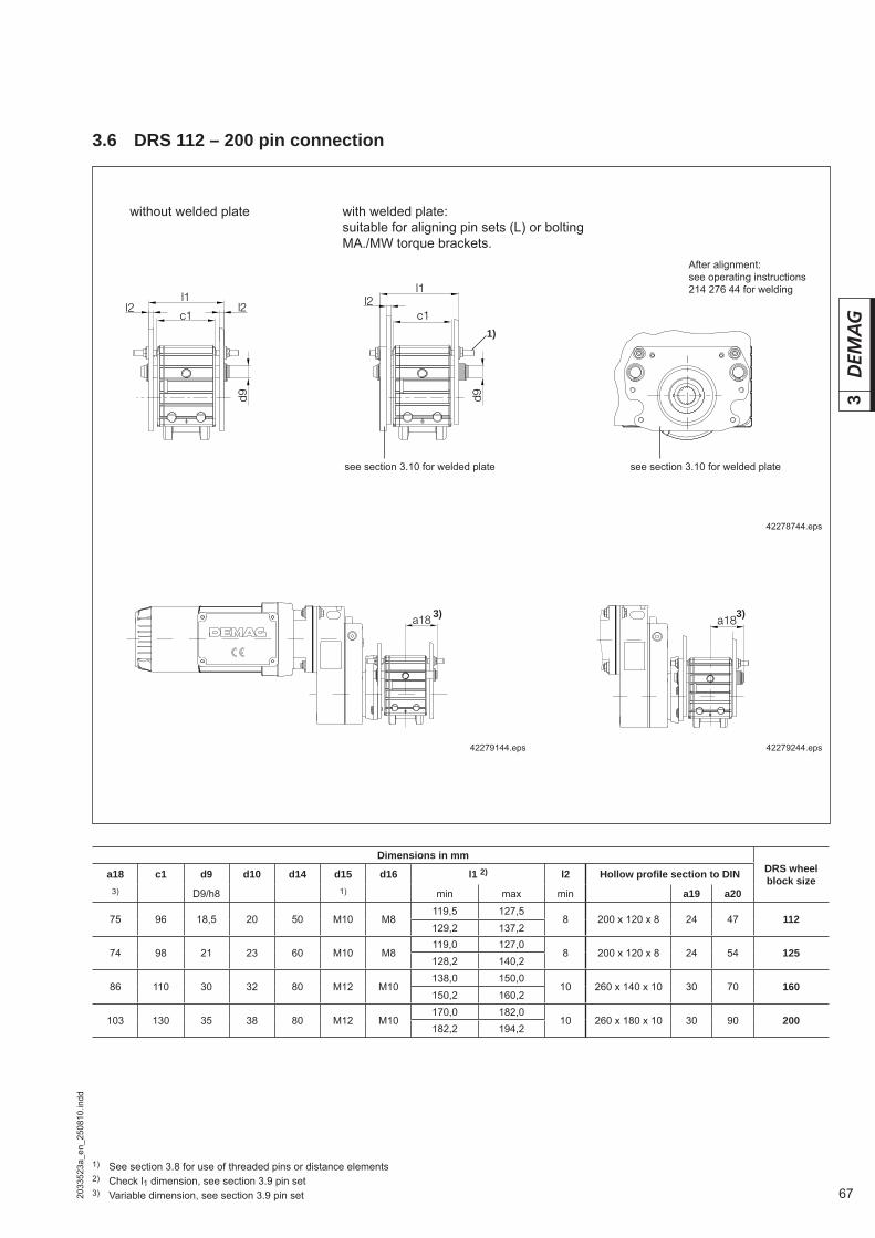
67
3
2033
523a
_en_
2508
10.in
dd
3.6 DRS 112 – 200 pin connection
42278744.eps
42279144.eps 42279244.eps
without welded plate with welded plate:suitable for aligning pin sets (L) or bolting MA./MW torque brackets.
After alignment:see operating instructions 214 276 44 for welding
see section 3.10 for welded plate
1) See section 3.8 for use of threaded pins or distance elements2) Check l1 dimension, see section 3.9 pin set3) Variable dimension, see section 3.9 pin set
1)
3) 3)
see section 3.10 for welded plate
Dimensions in mmDRS wheel block sizea18 c1 d9 d10 d14 d15 d16 l1 2) l2 Hollow profi le section to DIN
3) D9/h8 1) min max min a19 a20
75 96 18,5 20 50 M10 M8119,5 127,5
8 200 x 120 x 8 24 47 112129,2 137,2
74 98 21 23 60 M10 M8119,0 127,0
8 200 x 120 x 8 24 54 125128,2 140,2
86 110 30 32 80 M12 M10138,0 150,0
10 260 x 140 x 10 30 70 160 150,2 160,2
103 130 35 38 80 M12 M10170,0 182,0
10 260 x 180 x 10 30 90 200182,2 194,2
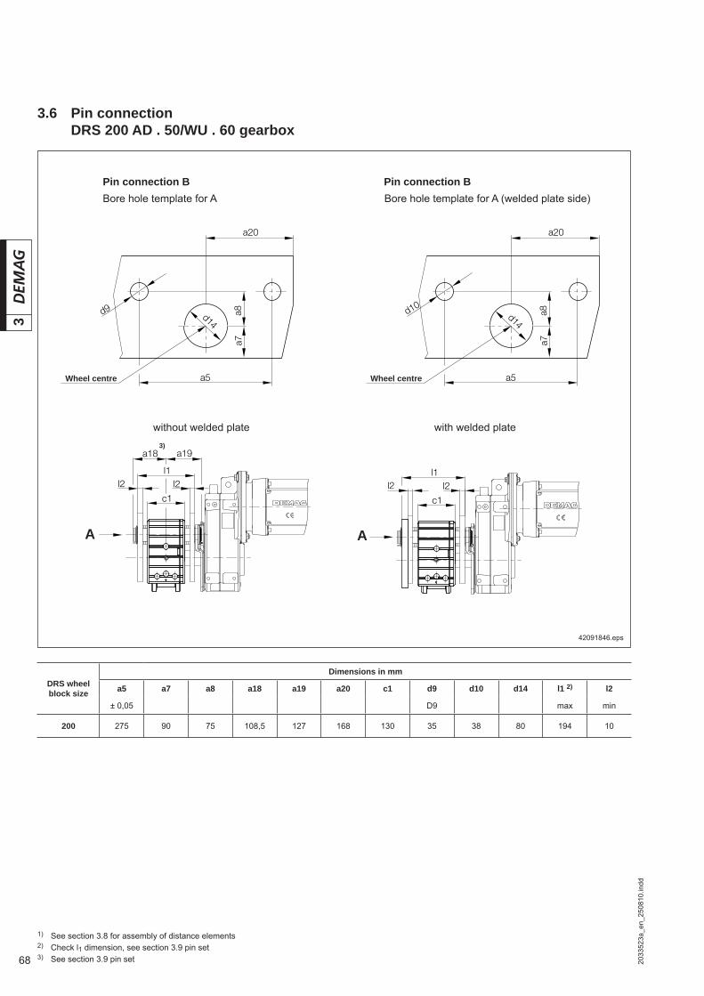
68
3
2033
523a
_en_
2508
10.in
dd42091846.eps
Wheel centre
1) See section 3.8 for assembly of distance elements2) Check l1 dimension, see section 3.9 pin set3) See section 3.9 pin set
3)
3.6 Pin connection DRS 200 AD . 50/WU . 60 gearbox
Pin connection B
A
without welded plate with welded plate
Wheel centre
A
Pin connection BBore hole template for A Bore hole template for A (welded plate side)
DRS wheel block size
Dimensions in mm
a5 a7 a8 a18 a19 a20 c1 d9 d10 d14 l1 2) l2
± 0,05 D9 max min
200 275 90 75 108,5 127 168 130 35 38 80 194 10
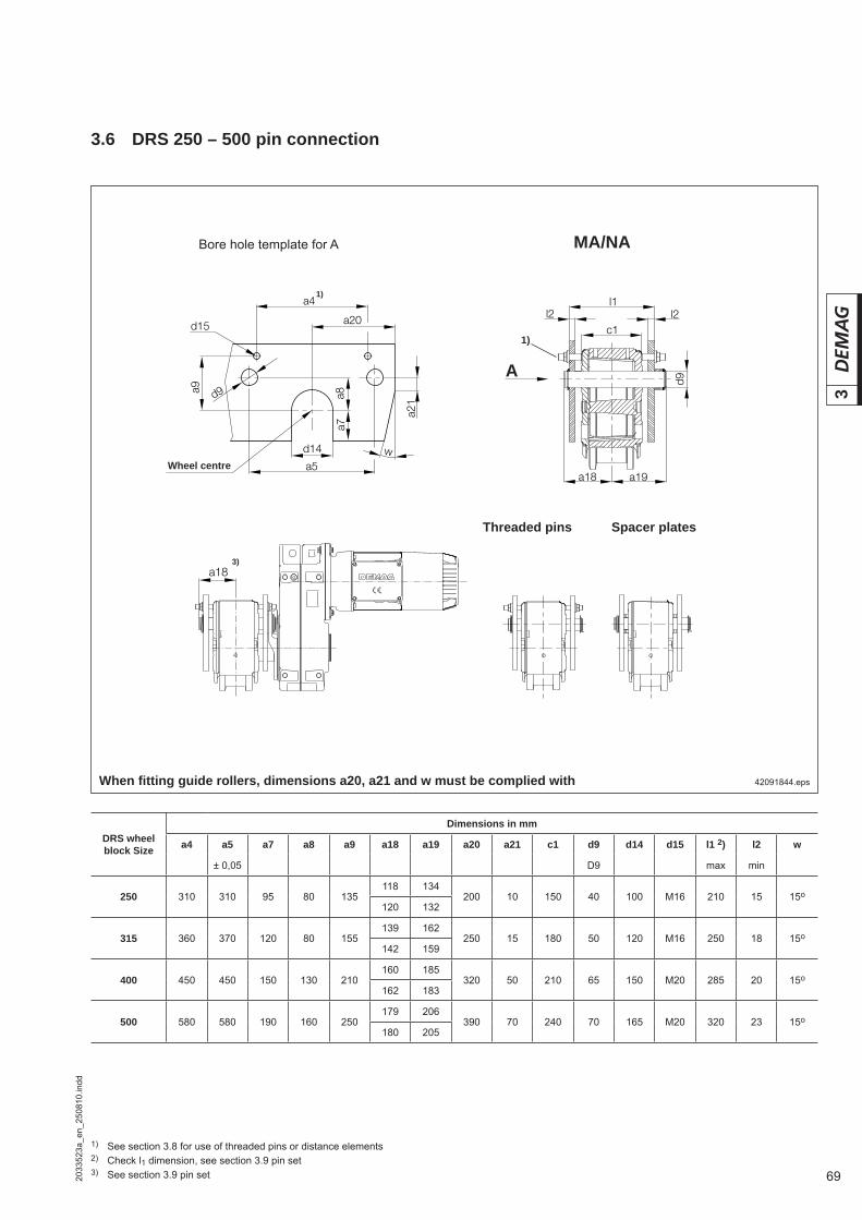
69
3
2033
523a
_en_
2508
10.in
dd
d14
a9
d15
w
a21
a4
d9
a20
a5
l2l2l1
c1
d9
a18 a19
a18
a7a8
3.6 DRS 250 – 500 pin connection
42091844.eps
Bore hole template for A
Wheel centre
When fi tting guide rollers, dimensions a20, a21 and w must be complied with
MA/NA
DRS wheel block Size
Dimensions in mm
a4 a5 a7 a8 a9 a18 a19 a20 a21 c1 d9 d14 d15 l1 2) l2 w
± 0,05 D9 max min
250 310 310 95 80 135118 134
200 10 150 40 100 M16 210 15 15o120 132
315 360 370 120 80 155139 162
250 15 180 50 120 M16 250 18 15o142 159
400 450 450 150 130 210160 185
320 50 210 65 150 M20 285 20 15o162 183
500 580 580 190 160 250179 206
390 70 240 70 165 M20 320 23 15o180 205
3)
1) See section 3.8 for use of threaded pins or distance elements2) Check l1 dimension, see section 3.9 pin set3) See section 3.9 pin set
1)
1)
A
Threaded pins Spacer plates

70
3
2033
523a
_en_
2508
10.in
dd
3.7 End connection
DRS wheel block size
Basic type
Dimensions in mm Options
Part no. a5 a6 a7 a8 a16 d9 d14 b1 b2 h l t1 t2 w1 w2 w3 Welded plate Pin set Spacer
plate set
1) 1) 1) 2)
112A
753 714 44 145 7 45 40 93 18,5 50 30 111 150 223 8 7 3 4 4753 829 44 753 738 44
752 139 44NA/MA – 753 737 44
125A
752 314 44 175 8 54 40 110 21,0 60 40 111 200 265 8 8 3 4 4752 429 44 752 338 44
752 140 44NA/MA – 752 337 44
160A
752 614 44 220 10 70 55 140 30,0 80 50 129 250 330 8 10 4 4 5752 729 44 752 638 44
752 141 44NA/MA – 752 637 44
200A
753 114 44 275 10 90 75 170 35,0 80 50 154 300 395 8 10 4 4 5753 229 44 753 138 44
752 142 44NA/MA – 753 137 44
41756744.eps
not included in scope of supply
DRS 112 – 200 end connection
Bore hole template for alignable end connection and axial securing arrangement with threaded pins (by the customer)
41681444.eps
DRS wheel block size
Dimensions in mm
a4 a6 a9 d10 d15
112 148 145 64 20M 10
125 162 175 72 23
160 206 220 90 32M 12
200 266 275 118 38
Side with welded plate
drilled by the customer
1) After aligning and tacking, fi rst weld on the inside and then the outside. Welded connections to tolerance class DIN 8570 BF assessment group DIN EN 25817 C
2) Required to fi t the torque bracket.

71
3
2033
523a
_en_
2508
10.in
dd
DRS wheel block size
Basic type Part no.
Dimensions in mm Options
a1 a2 a5 a6 b1 b2 d9 h h1 h2 L t1 t2 w w1 w2 w3 w4 Pin set Spacer plate set
1) 1) 1) 1)
250A
753 414 44 90 45 310 7 80 185 40 382 236 176 393 12 12 121° 4 4 5 5753 438 44
752 143 44NA/MA 753 437 44
42282744.eps
DRS 250 end connection
not included in scope of supply
1) After aligning and tacking, fi rst weld on the inside and then the outside. Welded connections to tolerance class DIN 8570 BF assessment group DIN EN 25817 C
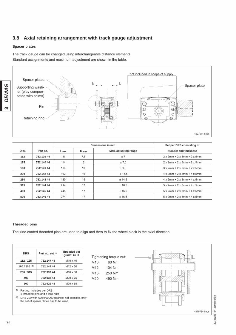
72
3
2033
523a
_en_
2508
10.in
dd
3.8 Axial retaining arrangement with track gauge adjustmentSpacer plates
The track gauge can be changed using interchangeable distance elements.Standard assignments and maximum adjustment are shown in the table.
42275744.eps
Spacer plateSpacer plates
Supporting wash-er (play compen-sated with shims)
Pin
Retaining ring
Dimensions in mm Set per DRS consisting of
DRS Part no. l max b max Max. adjusting range Number and thickness
112 752 139 44 111 7,5 ± 7 2 x 2mm + 2 x 3mm + 2 x 5mm
125 752 140 44 114 8 ± 7,5 2 x 2mm + 2 x 3mm + 2 x 5mm
160 752 141 44 130 10 ± 9,5 3 x 2mm + 2 x 3mm + 2 x 5mm
200 752 142 44 162 16 ± 15,5 4 x 2mm + 2 x 3mm + 4 x 5mm
250 752 143 44 180 15 ± 14,5 4 x 2mm + 2 x 3mm + 4 x 5mm
315 752 144 44 214 17 ± 16,5 5 x 2mm + 2 x 3mm + 4 x 5mm
400 752 145 44 245 17 ± 16,5 5 x 2mm + 2 x 3mm + 4 x 5mm
500 752 146 44 274 17 ± 16,5 5 x 2mm + 2 x 3mm + 4 x 5mm
Threaded pins
The zinc-coated threaded pins are used to align and then to fi x the wheel block in the axial direction.
41757344.eps
Tightening torque nut:M10: 060 NmM12: 104 NmM16: 250 NmM20: 490 Nm
1) Part no. includes per DRS: 4 threaded pins and 4 lock nuts2) DRS 200 with AD50/WU60 gearbox not possible, only
the set of spacer plates has to be used
DRS Part no. set 1) Threaded pin grade: 45 H
112 / 125 752 147 44 M10 x 40
160 / 200 2) 752 148 44 M12 x 50
250 / 315 752 937 44 M16 x 60
400 752 938 44 M20 x 75
500 752 929 44 M20 x 85
not included in scope of supply
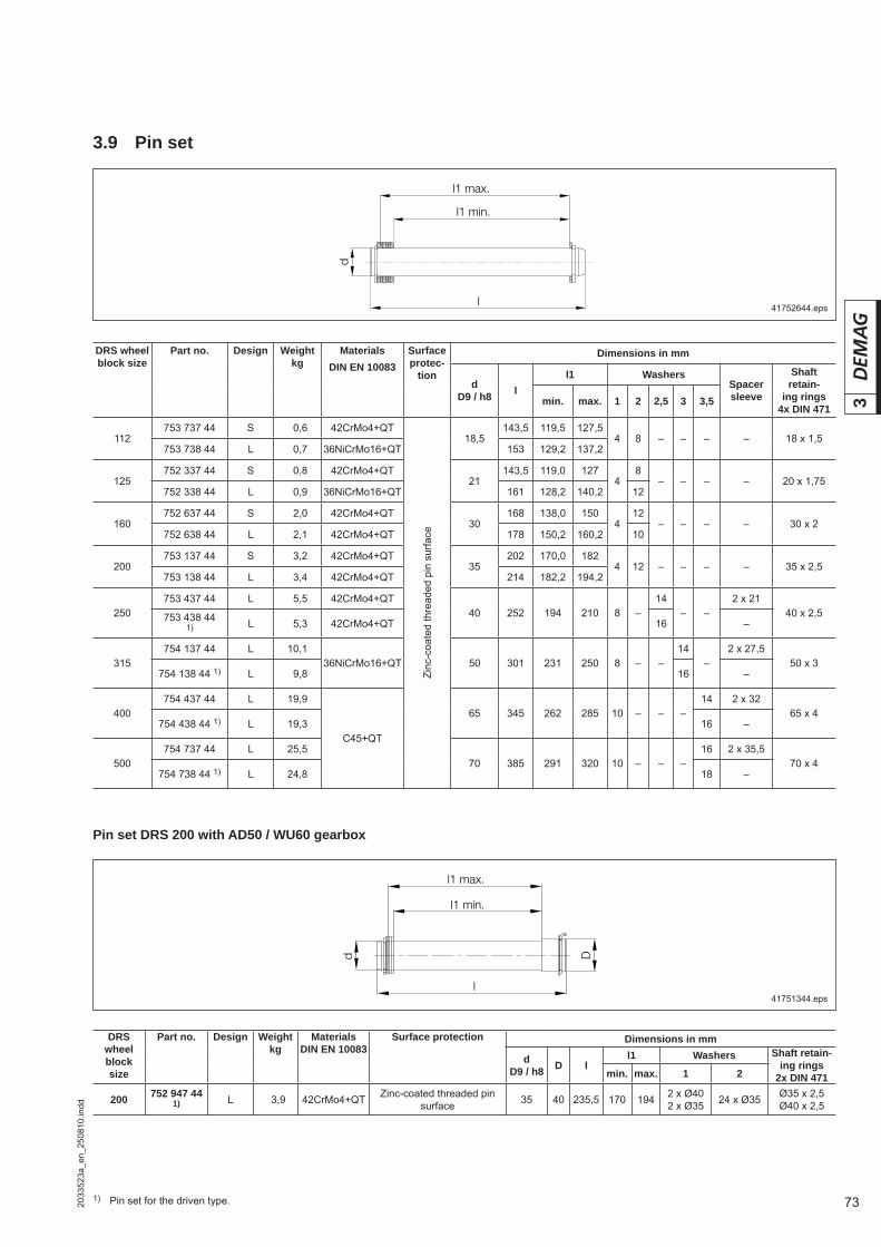
73
3
2033
523a
_en_
2508
10.in
dd
3.9 Pin set
41751344.eps
Pin set DRS 200 with AD50 / WU60 gearbox
41752644.eps
DRS wheel block size
Part no. Design Weight kg
MaterialsDIN EN 10083
Surface protection Dimensions in mm
dD9 / h8 D l
l1 Washers Shaft retain-ing rings
2x DIN 471min. max. 1 2
200 752 947 441) L 03,9 42CrMo4+QT Zinc-coated threaded pin
surface 35 40 235,5 170 194 2 x Ø402 x Ø35 24 x Ø35 Ø35 x 2,5
Ø40 x 2,5
DRS wheel block size
Part no. Design Weight kg
MaterialsDIN EN 10083
Surface protec-
tion
Dimensions in mm
dD9 / h8 l
l1 WashersSpacer sleeve
Shaft retain-
ing rings 4x DIN 471
min. max. 1 2 2,5 3 3,5
112753 737 44 S 00,6 42CrMo4+QT
Zinc
-coa
ted
thre
aded
pin
sur
face
18,5143,5 119,5 127,5
4 8 – – – – 18 x 1,5753 738 44 L 00,7 36NiCrMo16+QT 153 129,2 137,2
125752 337 44 S 00,8 42CrMo4+QT
21143,5 119,0 127
48
– – – – 20 x 1,75752 338 44 L 00,9 36NiCrMo16+QT 161 128,2 140,2 12
160752 637 44 S 02,0 42CrMo4+QT
30168 138,0 150
412
– – – – 30 x 2752 638 44 L 02,1 42CrMo4+QT 178 150,2 160,2 10
200753 137 44 S 03,2 42CrMo4+QT
35202 170,0 182
4 12 – – – – 35 x 2,5753 138 44 L 03,4 42CrMo4+QT 214 182,2 194,2
250753 437 44 L 05,5 42CrMo4+QT
40 252 194 210 8 –14
– –2 x 21
40 x 2,5753 438 441) L 05,3 42CrMo4+QT 16 –
315754 137 44 L 10,1
36NiCrMo16+QT 50 301 231 250 8 – –14
–2 x 27,5
50 x 3754 138 44 1) L 09,8 16 –
400754 437 44 L 19,9
C45+QT
65 345 262 285 10 – – –14 2 x 32
65 x 4754 438 44 1) L 19,3 16 –
500754 737 44 L 25,5
70 385 291 320 10 – – –16 2 x 35,5
70 x 4754 738 44 1) L 24,8 18 –
1) Pin set for the driven type.
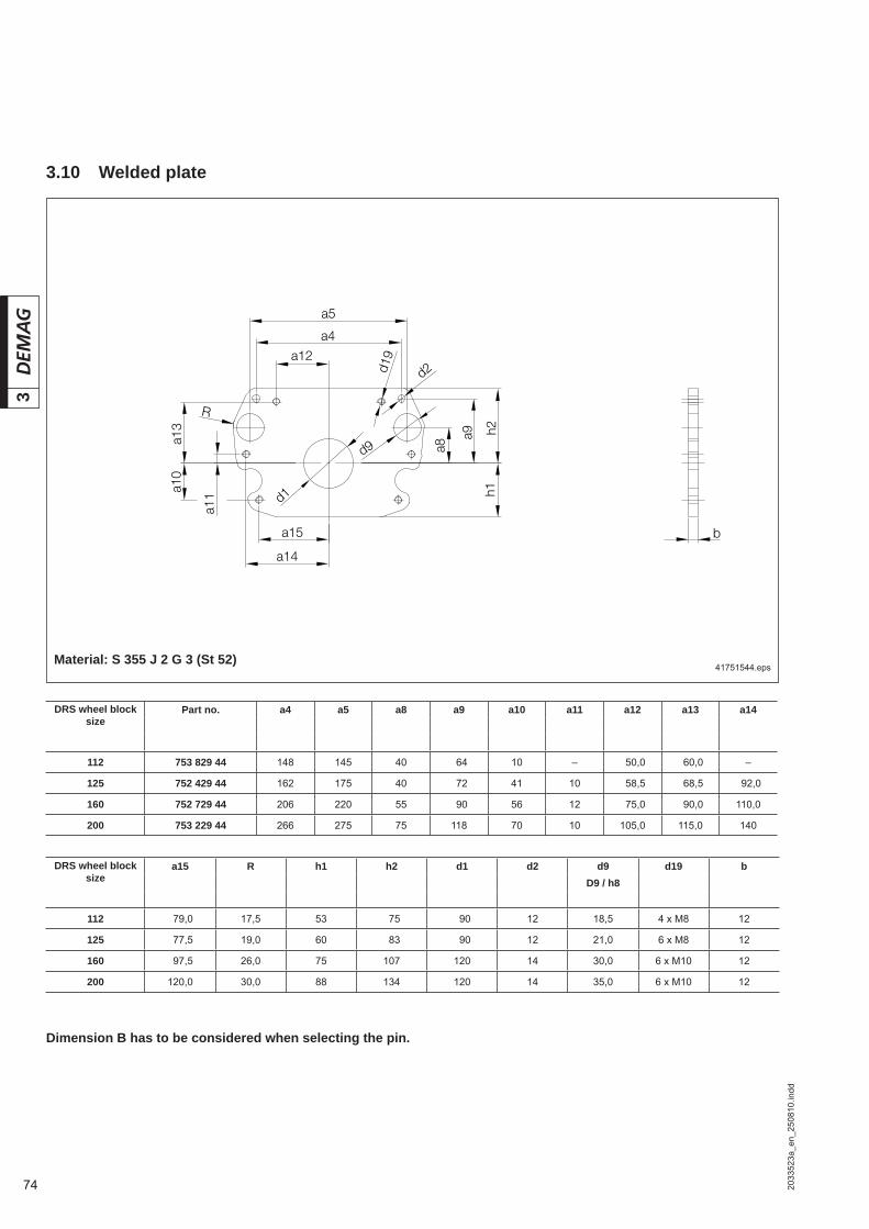
74
3
2033
523a
_en_
2508
10.in
dd
3.10 Welded plate
Dimension B has to be considered when selecting the pin.
41751544.eps
DRS wheel block size
Part no. a4 a5 a8 a9 a10 a11 a12 a13 a14
112 753 829 44 148 145 40 064 10 – 050,0 060,0 –
125 752 429 44 162 175 40 072 41 10 058,5 068,5 092,0
160 752 729 44 206 220 55 090 56 12 075,0 090,0 110,0
200 753 229 44 266 275 75 118 70 10 105,0 115,0 140
DRS wheel block size
a15 R h1 h2 d1 d2 d9 d19 bD9 / h8
112 079,0 17,5 53 075 090 12 18,5 4 x M8 12
125 077,5 19,0 60 083 090 12 21,0 6 x M8 12
160 097,5 26,0 75 107 120 14 30,0 6 x M10 12
200 120,0 30,0 88 134 120 14 35,0 6 x M10 12
Material: S 355 J 2 G 3 (St 52)

75
3
2033
523a
_en_
2508
10.in
dd
42204344.eps
Splined shaft profi le to DIN 5480(Pressure angle 30°)
Diametral checking dimension Me
Measuring pin diameterDM
W30x1,25x22 6g/7H 33,078 –0,0196 2,75
W35x2x16 6g/7H 38,972 –0,023 4
W45x2x21 6g/7H 48,907 –0,022 4
W50x2x24 6g/7H 54,187 –0,025 4
W65x2x31 6g/7H 69,024 –0,028 4
W75x3x24 6g/7H 81,292 –0,028 6
W90x3x28 6g/7H 95,945 –0,0265 6
W110x3x35 6g/7H 116,036 –0,0306 6
3.11 Shaft system
The Demag shaft system for DRS wheel blocks with drives from the Demag modular geared motor system consists of various shaft types:
Drive shaft Gearbox with solid shafts featuring involute splinesor shaft type A or type DFW for gearboxes with hollow shafts featuring involute splines.
Connecting shaft Type G for central drive units with offset or angular gearboxes in connection with a coupling.This shaft type must not be used as a drive shaft.
All shafts have a splined profi le to DIN 5480 with the following dimensions and checking dimensions:

76
3
2033
523a
_en_
2508
10.in
dd
3.11.1 Individual drive unit, consisting of:a) Offset gearbox with journal shafts: Torque bracket set (3), corresponding to connection variantb) Offset gearbox with hollow shaft: Torque bracket set (3), corresponding to connection variant and splined shaft
set (2)
With journal shaft With splined shaft
DRS wheel block size
Travel wheel hub
profi le
Toothed hub profi le for journal or hollow shafts Individual drive unit
AM. and AD. offset gearboxes Journal shafts 1) Splined shaft set 2)
10 20 30 40 50 60 70 80 90 K / W1 B / W2 K / W1, W2 / B
112N30 N30 30 (11) 30 (11) –
N30 N30 – – 860 090 46
125
N30 N30 30 31 –
N35 N35 35(11) 35(11) –
N35 N35 – – 860 190 46
160
N35 N35 35 36 –
N45 N45 45 (11) 45 (11) –
N45 N45 – – 860 290 46
200
N45 N45 45 46 –
N50 N50 50 (11) 50 (11) –
N50 N50 – – 860 390 46
250
N50 N50 50 51 –
N65 N65 65 (11) 66 (22) –
N65 N65 – – 860 490 46
315
N65 N65 66 66 –
N75 N75 75 (11) 76 (22) –
N75 N75 – – 860 590 46
400
N75 N75 76 76 –
N90 N90 90 (11) 91 (22) –
N90 N90 – – 860 690 46
500
N90 N90 91 91 –
N110 N110 110 111 –
N110 N110 – – 860 790 46
1) Output drive shaft code for individual drive unit, (..) output drive shaft code for central drive unit2) Part no. includes splined shaft, spacer rings and axial retaining elements
Offset gearbox with hollow shaft
42293244.eps 42293344.eps
K = Top connectionW = W1 (side connection with drive on wheel block side) W2 (side connection with drive on connecting plate side)B = Pin connection
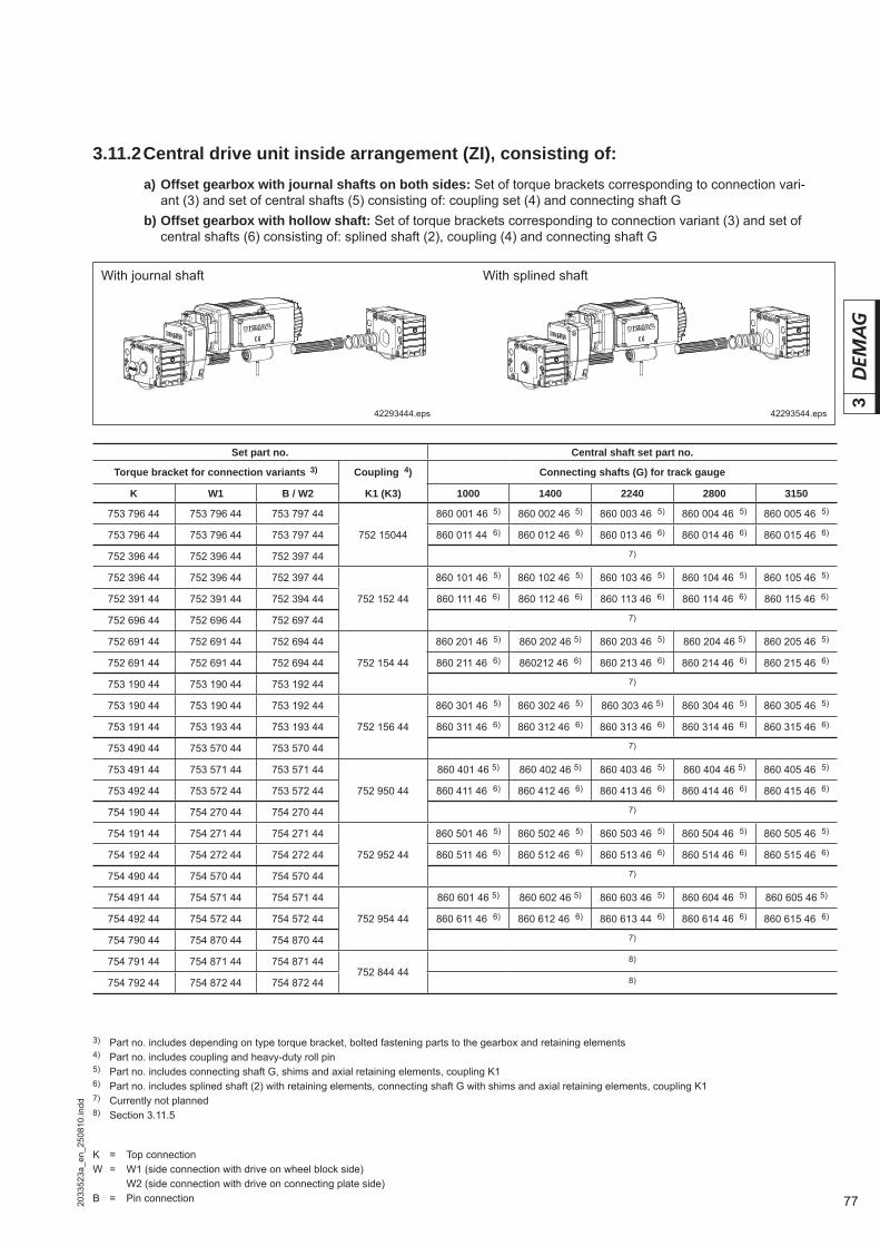
77
3
2033
523a
_en_
2508
10.in
dd
3.11.2 Central drive unit inside arrangement (ZI), consisting of:a) Offset gearbox with journal shafts on both sides: Set of torque brackets corresponding to connection vari-
ant (3) and set of central shafts (5) consisting of: coupling set (4) and connecting shaft Gb) Offset gearbox with hollow shaft: Set of torque brackets corresponding to connection variant (3) and set of
central shafts (6) consisting of: splined shaft (2), coupling (4) and connecting shaft G
With journal shaft With splined shaft
Set part no. Central shaft set part no.
Torque bracket for connection variants 3) Coupling 4) Connecting shafts (G) for track gauge
K W1 B / W2 K1 (K3) 1000 1400 2240 2800 3150
753 796 44 753 796 44 753 797 44
752 15044
860 001 46 5) 860 002 46 5) 860 003 46 5) 860 004 46 5) 860 005 46 5)
753 796 44 753 796 44 753 797 44 860 011 44 6) 860 012 46 6) 860 013 46 6) 860 014 46 6) 860 015 46 6)
752 396 44 752 396 44 752 397 44 7)
752 396 44 752 396 44 752 397 44
752 152 44
860 101 46 5) 860 102 46 5) 860 103 46 5) 860 104 46 5) 860 105 46 5)
752 391 44 752 391 44 752 394 44 860 111 46 6) 860 112 46 6) 860 113 46 6) 860 114 46 6) 860 115 46 6)
752 696 44 752 696 44 752 697 44 7)
752 691 44 752 691 44 752 694 44
752 154 44
860 201 46 5) 860 202 46 5) 860 203 46 5) 860 204 46 5) 860 205 46 5)
752 691 44 752 691 44 752 694 44 860 211 46 6) 860212 46 6) 860 213 46 6) 860 214 46 6) 860 215 46 6)
753 190 44 753 190 44 753 192 44 7)
753 190 44 753 190 44 753 192 44
752 156 44
860 301 46 5) 860 302 46 5) 860 303 46 5) 860 304 46 5) 860 305 46 5)
753 191 44 753 193 44 753 193 44 860 311 46 6) 860 312 46 6) 860 313 46 6) 860 314 46 6) 860 315 46 6)
753 490 44 753 570 44 753 570 44 7)
753 491 44 753 571 44 753 571 44
752 950 44
860 401 46 5) 860 402 46 5) 860 403 46 5) 860 404 46 5) 860 405 46 5)
753 492 44 753 572 44 753 572 44 860 411 46 6) 860 412 46 6) 860 413 46 6) 860 414 46 6) 860 415 46 6)
754 190 44 754 270 44 754 270 44 7)
754 191 44 754 271 44 754 271 44
752 952 44
860 501 46 5) 860 502 46 5) 860 503 46 5) 860 504 46 5) 860 505 46 5)
754 192 44 754 272 44 754 272 44 860 511 46 6) 860 512 46 6) 860 513 46 6) 860 514 46 6) 860 515 46 6)
754 490 44 754 570 44 754 570 44 7)
754 491 44 754 571 44 754 571 44
752 954 44
860 601 46 5) 860 602 46 5) 860 603 46 5) 860 604 46 5) 860 605 46 5)
754 492 44 754 572 44 754 572 44 860 611 46 6) 860 612 46 6) 860 613 44 6) 860 614 46 6) 860 615 46 6)
754 790 44 754 870 44 754 870 44 7)
754 791 44 754 871 44 754 871 44752 844 44
8)
754 792 44 754 872 44 754 872 44 8)
3) Part no. includes depending on type torque bracket, bolted fastening parts to the gearbox and retaining elements4) Part no. includes coupling and heavy-duty roll pin5) Part no. includes connecting shaft G, shims and axial retaining elements, coupling K16) Part no. includes splined shaft (2) with retaining elements, connecting shaft G with shims and axial retaining elements, coupling K17) Currently not planned8) Section 3.11.5
42293444.eps 42293544.eps
K = Top connectionW = W1 (side connection with drive on wheel block side) W2 (side connection with drive on connecting plate side)B = Pin connection
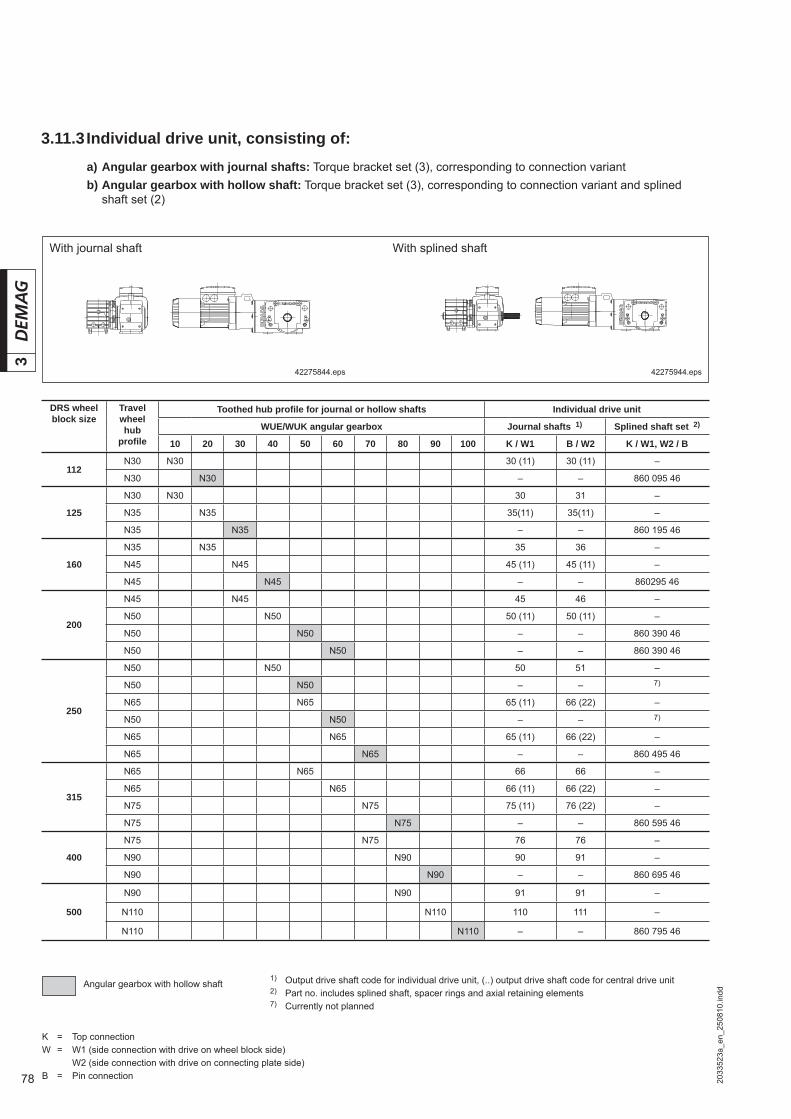
78
3
2033
523a
_en_
2508
10.in
dd
3.11.3 Individual drive unit, consisting of:a) Angular gearbox with journal shafts: Torque bracket set (3), corresponding to connection variantb) Angular gearbox with hollow shaft: Torque bracket set (3), corresponding to connection variant and splined
shaft set (2)
With journal shaft With splined shaft
DRS wheel block size
Travel wheel hub
profi le
Toothed hub profi le for journal or hollow shafts Individual drive unit
WUE/WUK angular gearbox Journal shafts 1) Splined shaft set 2)
10 20 30 40 50 60 70 80 90 100 K / W1 B / W2 K / W1, W2 / B
112N30 N30 30 (11) 30 (11) –
N30 N30 – – 860 095 46
125
N30 N30 30 31 –
N35 N35 35(11) 35(11) –
N35 N35 – – 860 195 46
160
N35 N35 35 36 –
N45 N45 45 (11) 45 (11) –
N45 N45 – – 860295 46
200
N45 N45 45 46 –
N50 N50 50 (11) 50 (11) –
N50 N50 – – 860 390 46
N50 N50 – – 860 390 46
250
N50 N50 50 51 –
N50 N50 – – 7)
N65 N65 65 (11) 66 (22) –
N50 N50 – – 7)
N65 N65 65 (11) 66 (22) –
N65 N65 – – 860 495 46
315
N65 N65 66 66 –
N65 N65 66 (11) 66 (22) –
N75 N75 75 (11) 76 (22) –
N75 N75 – – 860 595 46
400
N75 N75 76 76 –
N90 N90 90 91 –
N90 N90 – – 860 695 46
500
N90 N90 91 91 –
N110 N110 110 111 –
N110 N110 – – 860 795 46
1) Output drive shaft code for individual drive unit, (..) output drive shaft code for central drive unit2) Part no. includes splined shaft, spacer rings and axial retaining elements7) Currently not planned
Angular gearbox with hollow shaft
42275844.eps 42275944.eps
K = Top connectionW = W1 (side connection with drive on wheel block side) W2 (side connection with drive on connecting plate side)B = Pin connection
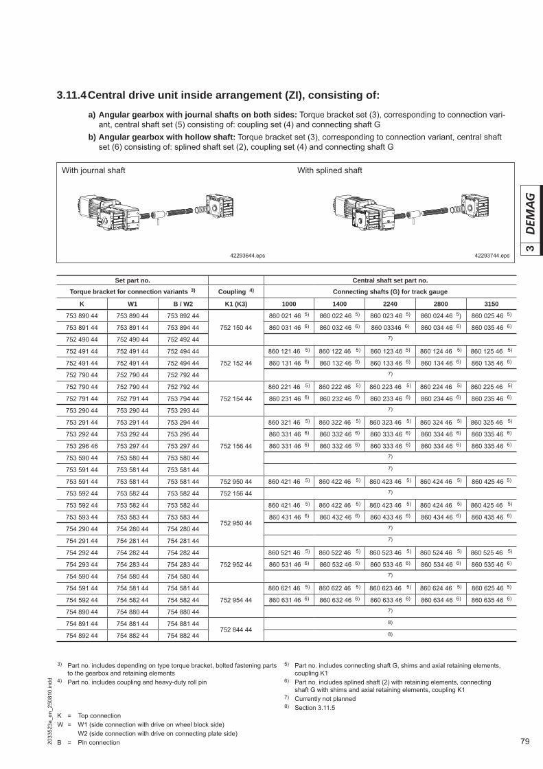
79
3
2033
523a
_en_
2508
10.in
dd
3.11.4 Central drive unit inside arrangement (ZI), consisting of:
With journal shaft With splined shaft
Set part no. Central shaft set part no.
Torque bracket for connection variants 3) Coupling 4) Connecting shafts (G) for track gauge
K W1 B / W2 K1 (K3) 1000 1400 2240 2800 3150
753 890 44 753 890 44 753 892 44
752 150 44
860 021 46 5) 860 022 46 5) 860 023 46 5) 860 024 46 5) 860 025 46 5)
753 891 44 753 891 44 753 894 44 860 031 46 6) 860 032 46 6) 860 03346 6) 860 034 46 6) 860 035 46 6)
752 490 44 752 490 44 752 492 44 7)
752 491 44 752 491 44 752 494 44
752 152 44
860 121 46 5) 860 122 46 5) 860 123 46 5) 860 124 46 5) 860 125 46 5)
752 491 44 752 491 44 752 494 44 860 131 46 6) 860 132 46 6) 860 133 46 6) 860 134 46 6) 860 135 46 6)
752 790 44 752 790 44 752 792 44 7)
752 790 44 752 790 44 752 792 44
752 154 44
860 221 46 5) 860 222 46 5) 860 223 46 5) 860 224 46 5) 860 225 46 5)
752 791 44 752 791 44 753 794 44 860 231 46 6) 860 232 46 6) 860 233 46 6) 860 234 46 6) 860 235 46 6)
753 290 44 753 290 44 753 293 44 7)
753 291 44 753 291 44 753 294 44
752 156 44
860 321 46 5) 860 322 46 5) 860 323 46 5) 860 324 46 5) 860 325 46 5)
753 292 44 753 292 44 753 295 44 860 331 46 6) 860 332 46 6) 860 333 46 6) 860 334 46 6) 860 335 46 6)
753 296 46 753 297 44 753 297 44 860 331 46 6) 860 332 46 6) 860 333 46 6) 860 334 46 6) 860 335 46 6)
753 590 44 753 580 44 753 580 44 7)
753 591 44 753 581 44 753 581 44 7)
753 591 44 753 581 44 753 581 44 752 950 44 860 421 46 5) 860 422 46 5) 860 423 46 5) 860 424 46 5) 860 425 46 5)
753 592 44 753 582 44 753 582 44 752 156 44 7)
753 592 44 753 582 44 753 582 44
752 950 44
860 421 46 5) 860 422 46 5) 860 423 46 5) 860 424 46 5) 860 425 46 5)
753 593 44 753 583 44 753 583 44 860 431 46 6) 860 432 46 6) 860 433 46 6) 860 434 46 6) 860 435 46 6)
754 290 44 754 280 44 754 280 44 7)
754 291 44 754 281 44 754 281 44 7)
754 292 44 754 282 44 754 282 44
752 952 44
860 521 46 5) 860 522 46 5) 860 523 46 5) 860 524 46 5) 860 525 46 5)
754 293 44 754 283 44 754 283 44 860 531 46 6) 860 532 46 6) 860 533 46 6) 860 534 46 6) 860 535 46 6)
754 590 44 754 580 44 754 580 44 7)
754 591 44 754 581 44 754 581 44
752 954 44
860 621 46 5) 860 622 46 5) 860 623 46 5) 860 624 46 5) 860 625 46 5)
754 592 44 754 582 44 754 582 44 860 631 46 6) 860 632 46 6) 860 633 46 6) 860 634 46 6) 860 635 46 6)
754 890 44 754 880 44 754 880 44 7)
754 891 44 754 881 44 754 881 44752 844 44
8)
754 892 44 754 882 44 754 882 44 8)
3) Part no. includes depending on type torque bracket, bolted fastening parts to the gearbox and retaining elements
4) Part no. includes coupling and heavy-duty roll pin
a) Angular gearbox with journal shafts on both sides: Torque bracket set (3), corresponding to connection vari-ant, central shaft set (5) consisting of: coupling set (4) and connecting shaft G
b) Angular gearbox with hollow shaft: Torque bracket set (3), corresponding to connection variant, central shaft set (6) consisting of: splined shaft set (2), coupling set (4) and connecting shaft G
42293644.eps 42293744.eps
K = Top connectionW = W1 (side connection with drive on wheel block side) W2 (side connection with drive on connecting plate side)B = Pin connection
5) Part no. includes connecting shaft G, shims and axial retaining elements, coupling K1
6) Part no. includes splined shaft (2) with retaining elements, connecting shaft G with shims and axial retaining elements, coupling K1
7) Currently not planned8) Section 3.11.5
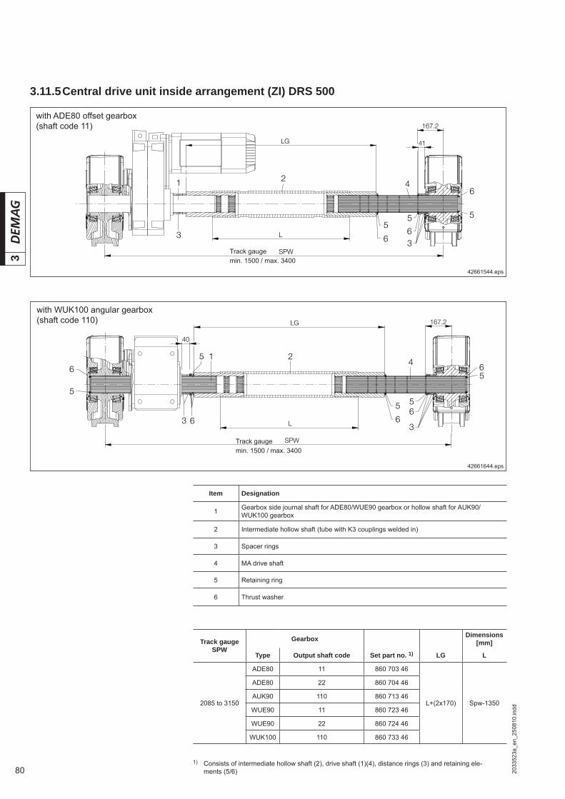
80
3
2033
523a
_en_
2508
10.in
dd
41
4
55
6
6
36
5
1 2
3
167.2
LG
L
SPW
3 6 6
5 56
3
14
167.2
2
LG
40
5
56
5
6
L
SPW
3.11.5 Central drive unit inside arrangement (ZI) DRS 500
with ADE80 offset gearbox(shaft code 11)
with WUK100 angular gearbox(shaft code 110)
Item Designation
1 Gearbox side journal shaft for ADE80/WUE90 gearbox or hollow shaft for AUK90/WUK100 gearbox
2 Intermediate hollow shaft (tube with K3 couplings welded in)
3 Spacer rings
4 MA drive shaft
5 Retaining ring
6 Thrust washer
Track gauge SPW
Gearbox Dimensions [mm]
Type Output shaft code Set part no. 1) LG L
2085 to 3150
ADE80 11 860 703 46
L+(2x170) Spw-1350
ADE80 22 860 704 46
AUK90 110 860 713 46
WUE90 11 860 723 46
WUE90 22 860 724 46
WUK100 110 860 733 46
1) Consists of intermediate hollow shaft (2), drive shaft (1)(4), distance rings (3) and retaining ele-ments (5/6)
42661544.eps
42661644.eps
Track gaugemin. 1500 / max. 3400
Track gaugemin. 1500 / max. 3400

81
3
2033
523a
_en_
2508
10.in
dd

82
3
2033
523a
_en_
2508
10.in
dd
3.12 Splined shaft type A
DRS wheel block size
Shaft profi le
DIN 5480
Gearbox size
Part no. Dimensions in mm
L L1 L2 L3 L4 L5 L6 L7 L8 L9
112 W30AMK20 860 090 46 308 205 216 226 33 15
–
WUK20 860 095 46 348 259 269 279 33 15
125 W35AMK30 860 190 46 332 224 234 244 31,4 15WUK30 860 195 46 382 285 295 305 31,4 15
160 W45AMK40 860 290 46 379 258 271 283 34,5 17,5WUK40 860 295 46 444 333 346 356 34,5 17,5
200 W50 ADK50WUK50/60 860 390 46 501 281 309 370 36 17,5 377 386 398 405
250 W65ADK60 860 490 46 488,5 356 393 – 70 10,5
–
WUK70 860 495 46 578 464 500 – 70 10,5
315 W75ADK70 860 590 46 587 445 489 – 86,5 13WUK80 860 595 46 682 509 553 – 86,5 13
400 W90ADK80 860 690 46 675 518 565 – 99,5 13,5WUK90 860 695 46 749 581 625 – 99,5 13,5
500 W110AUK90 860 790 46 793 594 639,5 – 111 13,5
WUK100 860 795 46 750 678,5 732 – 111 13,5
42280644.eps
42278244.eps
3.13 Splined shaft type DFW
DRS wheel block size
Shaft profi le DIN 5480
Gearbox size Part no. Dimensions in mm
L L1 L2 L3
112 W30 AMK 20 752 031 44 225 102 107,5 3,5
125 W35 AMK 30 752 033 44 250 121 129
5160 W45 AMK 40 752 035 44 305 139,5 147
200 W50 ADK 50 752 03744 327 164,5 172,5
250 W65 ADK 60 752 831 44 418 194,5 204
6315 W75 ADK 70 752 833 44 1)512
240,5 254
400 W90 ADK 80 752 835 44 1) 274 288,5
Wheel centre
Hollow shaft KWheel centre
DFW shafts can only be used with certain mo-tor/gearbox combinations. Please check with the manufacturer before using these shafts.
1) Delivery period on request
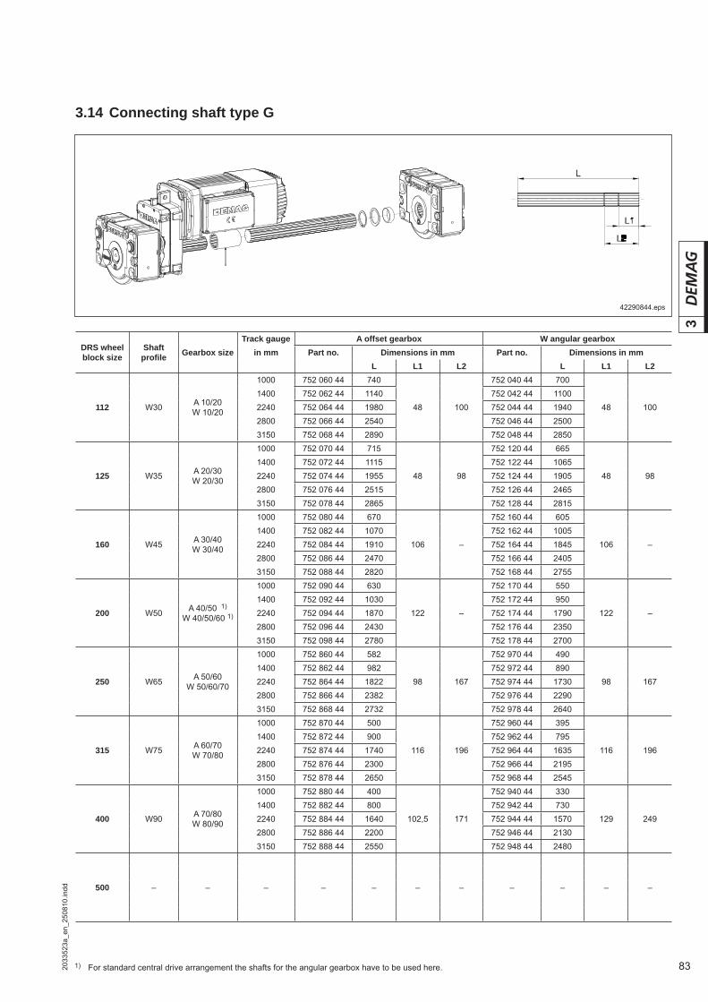
83
3
2033
523a
_en_
2508
10.in
dd
3.14 Connecting shaft type G
DRS wheel block size
Shaft profi le Gearbox size
Track gauge A offset gearbox W angular gearboxin mm Part no. Dimensions in mm Part no. Dimensions in mm
L L1 L2 L L1 L2
A 10/20W 10/20
1000 752 060 44 740 752 040 44 7001400 752 062 44 1140 752 042 44 1100
112 W30 2240 752 064 44 1980 48 100 752 044 44 1940 48 1002800 752 066 44 2540 752 046 44 25003150 752 068 44 2890 752 048 44 2850
A 20/30W 20/30
1000 752 070 44 715 752 120 44 6651400 752 072 44 1115 752 122 44 1065
125 W35 2240 752 074 44 1955 48 98 752 124 44 1905 48 982800 752 076 44 2515 752 126 44 24653150 752 078 44 2865 752 128 44 2815
A 30/40W 30/40
1000 752 080 44 670 752 160 44 6051400 752 082 44 1070 752 162 44 1005
160 W45 2240 752 084 44 1910 106 – 752 164 44 1845 106 –2800 752 086 44 2470 752 166 44 24053150 752 088 44 2820 752 168 44 2755
A 40/50 1)
W 40/50/60 1)
1000 752 090 44 630 752 170 44 5501400 752 092 44 1030 752 172 44 950
200 W50 2240 752 094 44 1870 122 – 752 174 44 1790 122 –2800 752 096 44 2430 752 176 44 23503150 752 098 44 2780 752 178 44 2700
A 50/60W 50/60/70
1000 752 860 44 582 752 970 44 4901400 752 862 44 982 752 972 44 890
250 W65 2240 752 864 44 1822 98 167 752 974 44 1730 98 1672800 752 866 44 2382 752 976 44 22903150 752 868 44 2732 752 978 44 2640
A 60/70W 70/80
1000 752 870 44 500 752 960 44 3951400 752 872 44 900 752 962 44 795
315 W75 2240 752 874 44 1740 116 196 752 964 44 1635 116 1962800 752 876 44 2300 752 966 44 21953150 752 878 44 2650 752 968 44 2545
A 70/80W 80/90
1000 752 880 44 400 752 940 44 3301400 752 882 44 800 752 942 44 730
400 W90 2240 752 884 44 1640 102,5 171 752 944 44 1570 129 2492800 752 886 44 2200 752 946 44 21303150 752 888 44 2550 752 948 44 2480
500 – – – – – – – – – – –
42290844.eps
1) For standard central drive arrangement the shafts for the angular gearbox have to be used here.
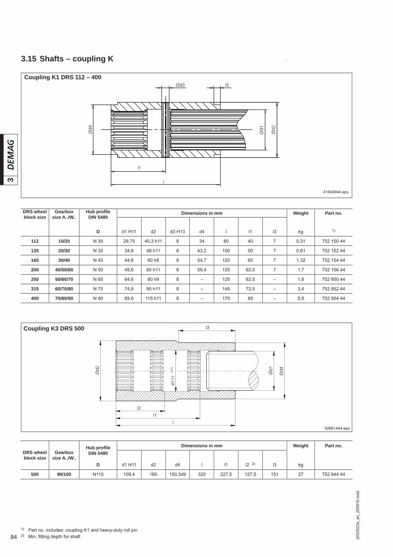
84
3
2033
523a
_en_
2508
10.in
dd
A-AA-A
l3
l1
l
Ød1
Ød4
Ød2
Ød3
41644944.eps
1) Part no. includes: coupling K1 and heavy-duty roll pin2) Min. fi tting depth for shaft
DRS wheel block size
Gearbox size A../W..
Hub profi le DIN 5480
Dimensions in mm Weight Part no.
D d1 H11 d2 d3 H13 d4 l l1 l3 kg 1)
112 10/20 N 30 29,75 40,3 h11 8 34 80 40 7 0,31 752 150 44
125 20/30 N 35 34,6 48 h11 8 43,2 100 50 7 0,81 752 152 44
160 30/40 N 45 44,6 60 h8 8 54,7 120 60 7 1,32 752 154 44
200 40/50/60 N 50 49,6 65 h11 8 59,4 125 62,5 7 1,7 752 156 44
250 50/60/70 N 65 64,6 80 h9 8 – 125 62,5 – 1,8 752 950 44
315 60/70/80 N 75 74,6 95 h11 8 – 145 72,5 – 3,4 752 952 44
400 70/80/90 N 90 89,6 115 h11 8 – 170 85 – 5,9 752 954 44
3.15 Shafts – coupling K
Coupling K3 DRS 500
DRS wheel block size
Gearbox size A../W..
Hub profi le DIN 5480
Dimensions in mm Weight Part no.
D d1 H11 d2 d4 l l1 l2 2) l3 kg
500 90/100 N110 109,4 160 150,3d9 320 227,5 127,5 151 27 752 844 44
l3
l2
l1
l
Ød1
Ød4Ød2
Ø11
1+
0,5
42661444.eps
Coupling K1 DRS 112 – 400
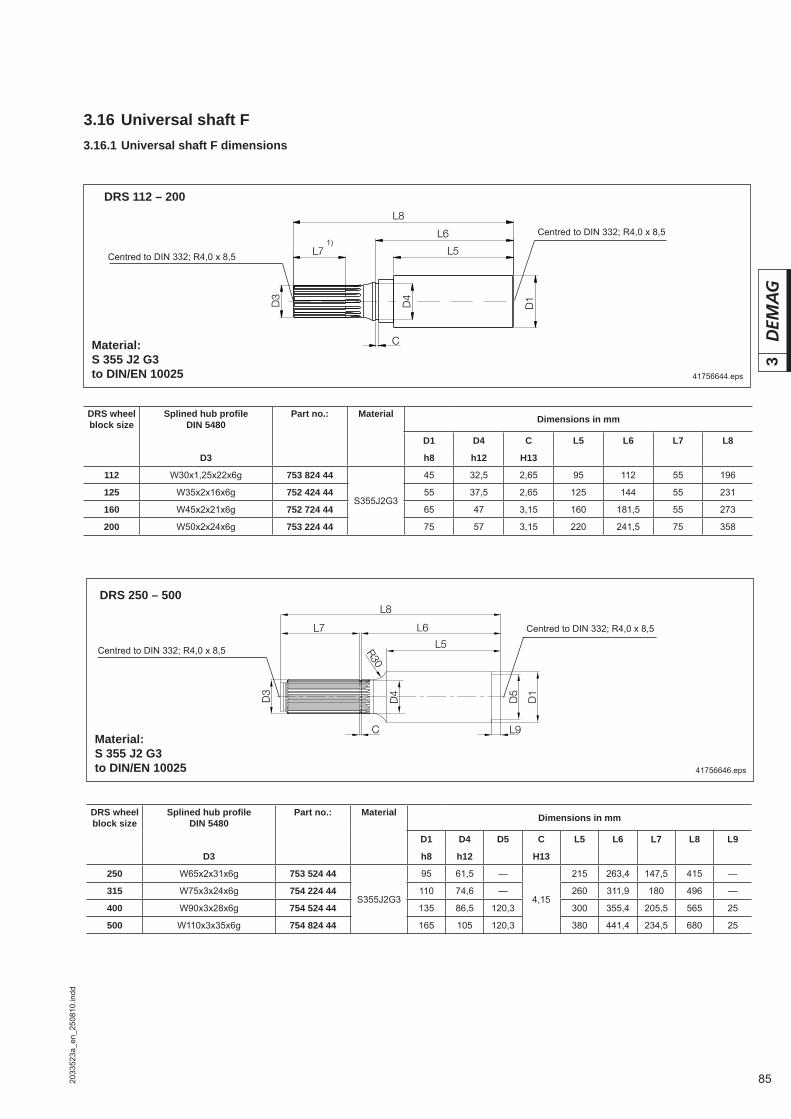
85
3
2033
523a
_en_
2508
10.in
dd
R30
D3
L7
C
L8
D4
L5
L6
D1
D5
L9
DRS 112 – 200
3.16 Universal shaft F
41756644.eps
1)
Material:S 355 J2 G3to DIN/EN 10025
41756646.eps
Material:S 355 J2 G3to DIN/EN 10025
DRS 250 – 500
DRS wheel block size
Splined hub profi le DIN 5480
Part no.: Material Dimensions in mm
D1 D4 C L5 L6 L7 L8
D3 h8 h12 H13
112 W30x1,25x22x6g 753 824 44
S355J2G3
45 32,5 2,65 95 112 55 196
125 W35x2x16x6g 752 424 44 55 37,5 2,65 125 144 55 231
160 W45x2x21x6g 752 724 44 65 47 3,15 160 181,5 55 273
200 W50x2x24x6g 753 224 44 75 57 3,15 220 241,5 75 358
DRS wheel block size
Splined hub profi le DIN 5480
Part no.: Material Dimensions in mm
D1 D4 D5 C L5 L6 L7 L8 L9
D3 h8 h12 H13
250 W65x2x31x6g 753 524 44
S355J2G3
95 61,5 —
4,15
215 263,4 147,5 415 —
315 W75x3x24x6g 754 224 44 110 74,6 — 260 311,9 180 496 —
400 W90x3x28x6g 754 524 44 135 86,5 120,3 300 355,4 205,5 565 25
500 W110x3x35x6g 754 824 44 165 105 120,3 380 441,4 234,5 680 25
Centred to DIN 332; R4,0 x 8,5
Centred to DIN 332; R4,0 x 8,5
Centred to DIN 332; R4,0 x 8,5
Centred to DIN 332; R4,0 x 8,5
3.16.1 Universal shaft F dimensions

86
3
2033
523a
_en_
2508
10.in
dd
3.16.2 Universal shaft F dimensions for DRS 112 – 200
Top connection K (basic wheel block type A)
42293944.eps
42294044.eps
Side connection W (basic wheel block type MA)
42294244.eps
42294344.eps
Pin connection B (basic wheel block type MA)
42294444.eps
42278144.eps
Section A-AConnecting plate centred using roll pins.
Section A-AConnecting plate centred using adapter nut.
Section A-AConnecting plate centred using pins.
Connecting plateBearing seat
Drive shaft F
Connecting plate
Bearing seatDrive shaft F
Connecting plate
Bearing seatDrive shaft F
1) Dimensions L1, L2 and L3 vary depending on dimension L42) Part no. includes drive shaft, connecting plate, bearing sleeve with corresponding mounting parts3) Specify A40 offset gearbox for wheel block type code
DRS wheel block size
Shaft profi le
DIN 5480
Connection variant Part no. Dimensions in mm2) D1 D2 L1 L2 L3 L4
h8 max.
112 W 30
K 753 820 44
45
90
160 72 36 –W 753 821 44
B 1) 753 822 44 178 88 18 127
125 W 35
K 752 420 44
55193 76 38 –
W 752 421 44
B 1) 752 422 44 209 92 22 130
160 W 45
K 752 720 44
65
120
235 85 38 –W 752 721 44
B 1) 752 722 44 254 104 20 148
200 W 50
K 753 220 44 3)
75305 95 53 –
W 753 221 44
B 1) 753 222 44 331 121 27 182
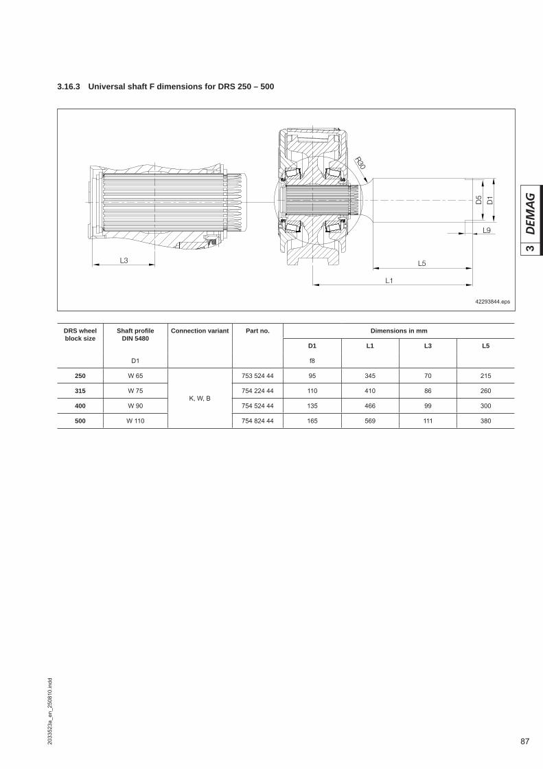
87
3
2033
523a
_en_
2508
10.in
dd
3.16.3 Universal shaft F dimensions for DRS 250 – 500
42293844.eps
DRS wheel block size
Shaft profi le DIN 5480
Connection variant Part no. Dimensions in mm
D1 L1 L3 L5
D1 f8
250 W 65
K, W, B
753 524 44 95 345 70 215
315 W 75 754 224 44 110 410 86 260
400 W 90 754 524 44 135 466 99 300
500 W 110 754 824 44 165 569 111 380
L3
L1
L5
R30
D1
D5
L9
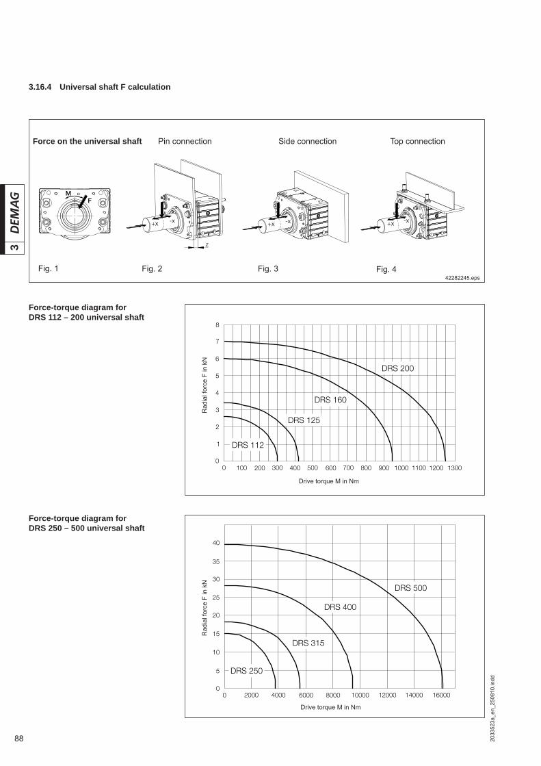
88
3
2033
523a
_en_
2508
10.in
dd
3.16.4 Universal shaft F calculation
Pin connection Side connection Top connectionForce on the universal shaft
42282245.eps
Force-torque diagram for DRS 112 – 200 universal shaft
Force-torque diagram for DRS 250 – 500 universal shaft
Rad
ial f
orce
F in
kN
Rad
ial f
orce
F in
kN
Drive torque M in Nm
Fig. 1 Fig. 2 Fig. 4Fig. 3
z
+x -x -x+x+x -x
FM
Drive torque M in Nm

89
3
2033
523a
_en_
2508
10.in
dd
Fperm (DRS,x) = Permissible force in N on the DRS universal shaft depending on the wheel block size and variable x
F(M) = Universal shaft force in N according to the diagramHF = Constant depending on the wheel block sizex = Variable when force F is displaced from the centre of the universal
shaft shoulder (see fi g. 2 – 4)
Calculate the permissible universal shaft force (only applies for reduction at x > 0 mm, otherwise direct F(M) from diagram)
Calculate the permissible remaining load capacity of the wheel blockFactor K (DRS, x, z) is given in table 1 (values for x = 0 mm and z = 0 mm)
K (DRS,x,z) = Factor for the force ratios on the universal shaft of the DRS de-pending on the wheel block size and variables x and z (see table 1)
HF = Constant depending on the wheel block sizex = Variable for displacement of force F from the centre of the universal
shaft shoulder (see fi g. 2 – 4)z = Variable for additional distance between bearing plate and wheel
block, e. g. for pin connection (see fi g. 2 – 4)
R perm (DRS,x,z) = Permissible residual load capacity of the wheel block for univer-sal shaft application in kg
Rperm (catalogue) = Permissible load capacity of the wheel block in kg according to the catalogue (without universal shaft)
K (DRS,x,z) = Factor for the force ratios on the universal shaft of the DRS de-pending on the wheel block size and variables x and z
= Angle deviation of the universal shaft force [0º 90º] (see fi g. 1)
Table 1 Table 2Permissible distance between DRS wall and bearing plate rear side (see pin connection fi g. 2)
DRS HF HDRSFactor K atx = 0 mmz = 0 mm
112 54,5 58 0,940
125 63,5 59 1,076
160 86 66 1,303
200 119 76 1,566
250 162,5 75 2,167
315 190 90 2,112
400 211 105 2,009
500 259 120 2,158
DRS zin mm
112 24 ≥ z ≥ 0
125 26 ≥ z ≥ 0
160 28 ≥ z ≥ 0
200 38 ≥ z ≥ 0
Rperm (DRS,x,z) = Rperm (catalogue) – F · K(DRS,x,z) · cos(0,8 · α)
9,81
Fperm (DRS,x,z) = F(M) · HF + x
HDRS + z
Fperm (DRS,x) = F(M) · HF
HF + x
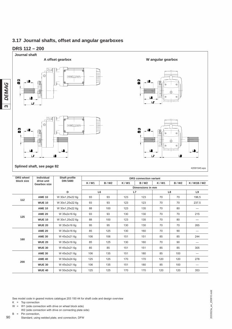
90
3
2033
523a
_en_
2508
10.in
dd
3.17 Journal shafts, offset and angular gearboxes
A offset gearbox
42091545.eps
W angular gearbox
See model code in geared motors catalogue 203 150 44 for shaft code and design overviewK = Top connectionW = W1 (side connection with drive on wheel block side) W2 (side connection with drive on connecting plate side)B = Pin connection, Standard, using welded plate, end connection, DFW
Journal shaft
DRS wheel block size
Individual drive unit
Gearbox size
Shaft profi le DIN 5480
DRS connection variantK / W1 B / W2 K / W1 B / W2 K / W1 B / W2 K / W1B / W2
Dimensions in mmD L6 L7 L8 L9
112AME 10 W 30x1,25x22 6g 93 93 123 123 70 70 196,5
WUE 10 W 30x1,25x22 6g 93 93 123 123 70 70 237,5
125
AME 10 W 30x1,25x22 6g 88 100 123 135 70 80 —
AME 20 W 35x2x16 6g 93 93 130 130 70 70 215
WUE 10 W 30x1,25x22 6g 88 100 123 135 70 80 —
WUE 20 W 35x2x16 6g 95 95 130 130 70 70 265
160
AME 20 W 35x2x16 6g 85 125 130 160 70 90 —
AME 30 W 45x2x21 6g 106 106 151 151 85 85 244
WUE 20 W 35x2x16 6g 85 125 130 160 70 90 —
WUE 30 W 45x2x21 6g 85 85 151 151 85 85 305
200
AME 30 W 45x2x21 6g 106 135 151 180 85 100 —
AME 40 W 50x2x24 6g 125 125 170 170 120 120 278
WUE 30 W 45x2x21 6g 106 135 151 180 85 100 —
WUE 40 W 50x2x24 6g 125 125 170 170 120 120 353
Splined shaft, see page 82
DRS 112 – 200

91
3
2033
523a
_en_
2508
10.in
dd
42091445.eps
DRS 250 – 500
A offset gearbox W angular gearboxJournal shaft
DRS wheel block size
Individual drive unit
Gearbox size
Shaft profi le DIN 5480
DRS connection variant
K / W1 B / W2 K / W1 B / W2 K / W1 B / W2 K / W1 B / W2Dimensions in mm
D L6 L7 L8 L9
250
ADE 40 W 50x2x24 6g 137 166 170 199 120 150 — —ADE 50 W 65x2x31 6g 144 181 177 214 138 174 312 347WUE 40 W 50x2x24 6g 147 147 180 180 130 130 — —WUE 50 W 65x2x31 6g 140 181 173 214 128 174 381 422WUE 60 W 65x2x31 6g 137 181 170 214 125 174 401 445
315
ADE 50 W 65x2x31 6g 174 174 214 214 185 185 — —ADE 60 W 75x3x24 6g 174 210 214 250 170 205 375 411WUE 50 W 65x2x31 6g 181 181 214 214 174 174 — —WUE 60 W 65x2x31 6g 181 181 214 214 174 174 — —WUE 70 W 75x3x24 6g 174 210 214 250 170 206 484 520
400
ADE 60 W 75x3x24 6g 201 201 250 250 205 205 — —
ADE 70 W 90x3x28 6g 203 237 252 286 200 245 462 496
WUE 70 W 75x3x24 6g 201 201 250 250 206 206 — —
WUE 80 W 90x3,0x28 6g 203 237 252 286 200 230 527 564
500
ADE 70 W 90x3,0x28 6g 232 232 286 286 200 230 — —
ADE 80 W 110x3,0x35 6g 231 271 285 325 220 260 532 572
WUE 80 W 90x3,0x28 6g 232 232 286 286 200 230 — —
WUE 90 W 110x3,0x35 6g 231 271 285 325 220 260 595 635
Splined shaft, see page 82
See model code in geared motors catalogue 203 150 44 for shaft code and design overview K = Top connectionW = W1 (side connection with drive on wheel block side) W2 (side connection with drive on connecting plate side)B = Pin connection, Standard, using welded plate, end connection, DFW

92 2033
523b
_en_
2508
10.in
dd
3
42096444.eps
3.18.1 DRS 112 – 200 wheel block with offset gearbox and ZBF/ZBA motor
For travel wheel types E, C and F see section 3.1
A 10 – A 40 2 and 3-stage direct input
(...) Torque bracket obstacle edge
DRS wheel block size
Gearbox size
Motor k12 k13 p11 b5 o g g1 g2 h1 h2 h21 h22 x xk x1 y dv
2-stage 3-stage
ZBF ZBA DD TD
112
AME 10 63A/71A 63A/B/71A/B 501 –
165 81336 140 124 140
91,5 51 56161,5
153
142+5
103
4 x M20
80A 80A/B/90A 557 – 392 157 134 157 170 155 4 x M25
AMK 20
63A/71A 63A/B/71A/B 512
176 81
336 140 124 140
104 57,5 56
174 142–2
(+5)
4 x M20
80A 80A/B/90A 568 392 157 134 157 182,5 155 4 x M25
90B/100A 90B/100A/B 612 – 436 196 152 196 202 179 167 133 2 x M252 x M32
125
AME 10 63A/71A 63A/B/71A/B 507 –
171 87336 140 124 140
91,5 51 62,5161,5
153
142+12
103
4 x M20
80A 80A/B/90A 563 – 392 157 134 157 170 155 4 x M25
AME 20
63A/71A 63A/B/71A/B 518
182 87
336 140 124 140
104 57,5 62,5
174 142
+5
4 x M20
80A 80A/B/90A 574 392 157 134 157 182,5 155 4 x M25
90B/100A 90B/100A/B 618 – 436 196 152 196 202 168 167 2 x M252 x M32
AMK 30
63A/71A 63A/B/71A/B 527
191 88
336 140 124 160
129 75 62,5
209153
142
–13
4 x M20
80A 80/90A 583 392 157 134 157 207,5 155 4 x M25
90B/100A 90B/100A/B 627 436 196 152 196 227 168 167 133 2 x M252 x M32
112A 112A769 – 578 260 185 260 259 273 222 173 2 x M40
2 x M50132A/B 132A/B/C
160
AME 20
63A/71A 63A/B/71A/B 534
198 103
336 140 124 140
104 57,5 80
174153
142
+23
103
4 x M20
80A 80A/B/90A 590 392 157 134 157 182,5 155 4 x M25
90B/100A 90B/100A/B 634 – 436 196 152 196 202 168 167 2 x M252 x M32
AME 30
63A/71A 63A/B/71A/B 543
207 104
336 140 124 160
129 75 80
209153
142
+5
4 x M20
80A 80A/B/90A 599 392 157 134 157 207,5 155 4 x M25
90B/100A 90B/100A/B 643 436 196 152 196 227 168 167 133 2 x M252 x M32
112A 112A785 – 578 260 185 260 259 273 222 173 2 x M40
2 x M50132A/B 132A/B/C
AMK 40
63A/71A 63A/B/71A/B 552
216 104
336 140 124 160
148 90 80
228153
142
–10(+5)
1034 x M20
80A 80A/B/90A 608 392 157 134 157 226,5 155 4 x M25
90B/100A 90B/100A/B 652 436 196 152 196 246 168 167 133 2 x M252 x M32
112A 112A794 – 578 260 185 260 278 273 222 173 2 x M40
2 x M50132A/B 132A/B/C
3.18 Dimensions of travel drive with offset geared motor, direct input
3.18.1.1 DRS 112 – 200 with A 10 - A 40, 2 and 3-stages

932033
523b
_en_
2508
10.in
dd
342096544.eps
A 50 2 and 3-stage direct input
For travel wheel types E, C and F see section 3.1
System end shield
(...) Torque bracket obstacle edge
(...) Torque bracket obstacle edge
DRS wheel
block size
Gearbox size
Motor k12 k13 p11 b5 o g g1 g2 h1 h2 h21 h22 x xk x1 y dv2-stage 3-stage
ZBF ZBA DD TD
200
AME 30
63A/71A 63A/B/71A/B 553
217 114
336 140 124 160
129 75 100
209153
142
+25
1034 x M20
80A 80A/B/90A 609 392 157 134 157 207,5 155 4 x M25
90B/100A 90B/100A/B 653 436 196 152 196 227 167 167 133 2 x M252 x M32
112A 112A795 – 578 260 185 260 259 273 222 173 2 x M40
2 x M50132A/B 132A/B/C
AME 40
63A/71A 63A/B/71A/B 562
226 114
336 140 124 140
148 90 100
218153
142
+10(+15)
1034 x M20
80A 80A/B/90A 618 392 157 134 157 226,5 155 4 x M25
90B/100A 90B/100A/B 662 436 196 152 196 246 167 167 133 2 x M252 x M32
112A 112A804 578 260 185 260 278 273 222 173 2 x M40
2 x M50132A/B 132A/B/C
DRS wheel block size
Gearbox size
Motor k12 k13 p11 b5 o g g1 g2 h1 h2 h21 h22 x xk x1 y dv2-stage 3-stage
ZBF ZBA DD TD
80A 80A/B/90A 622
230 98
392 157 134250
178 115 100
303153 155
-15(+15)
103 4 x M25
90B/100A 90B/100A/B 666 436 196 152 168 167 133 2 x M252 x M32
200 ADK 50 112A 112A808 578 260 185 260 308
273222
173 2 x M402 x M50132A/B 132A/B/C
– 160A/B/180A 917 687 314 269 276 335 236
3.18.1.2 DRS 200 with A 50, 2 and 3-stages

94 2033
523b
_en_
2508
10.in
dd
3
42096644.eps
3.18.2 DRS 250 – 500 wheel block with offset gearbox and ZBF/ZBA motor
A 40 – A 90 2 and 3-stage direct input
For travel wheel types E, C and F see section 3.2
(...) Torque bracket obstacle edge
DRS wheel
block size
Gearbox size
Motor k12 k13 p11 b5 o g g1 g2 h1 h2 h21 h22 x xk x1 y dv
2-stage 3-stage
ZBF ZBA DD TD
250
ADE 40
63A/71A 63A/B/71A/B 556
220 108
336 140 124 160
148 90 125
218153
142
+35(+20)
1034 x M20
80A 80A/B/90A 612 392 157 134 157 226,5 155 4 x M25
90B/100A 90B/100A/B 656 436 196 152 196 246 168 167 133 2 x M252 x M32
112A 112A798 578 260 185 260 278 273 222 173 2 x M40
2 x M50132A/B 132A/B/C
ADE 50
80A 80A/B/90A 632
240 108
392 157 134250
178 115 125
303153 155
+10(+20)
103 4 x M25
90B/100A 90B/100A/B 676 436 196 152 168 167 133 2 x M252 x M32
112A 112A818 578 260 185 260 308
273222
173 2 x M402 x M50132A/B 132A/B/C
– 160A/B/180A 927 687 314 269 276 335 236
ADK 60
80A 80A/B/90A 656
265 108
392 157 134250
218 140 125
343153 155
–15(+20)
103 4 x M25
90B/100A 90B/100A/B 700 436 196 152 168 167 133 2 x M252 x M32
112A 112A842 578 260 185 260 348
273222
173 2 x M402 x M50132A/B 132A/B/C
– 160A/B/180A 953 687 314 269 276 375 236
315
ADE 50
80A 80A/B/90A 654
262 130
392 157 134250
178 115 157,5
303153 155
+43(+29)
103 4 x M25
90B/100A 90B/100A/B 698 436 196 152 168 167 133 2 x M252 x M32
112A 112A840 578 260 185 260 308
273222
173 2 x M402 x M50132A/B 132A/B/C
– 160A/B/180A 949 687 314 269 276 335 236
ADE 60
80A 80A/B/90A 679
287 130
392 157 134250
218 140 157,5
343153 155
+12(+17)
103 4 x M25
90B/100A 90B/100A/B 723 436 196 152 168 167 133 2 x M252 x M32
112A 112A865 578 260 185 260 348
273222
173 2 x M402 x M50132A/B 132A/B/C
– 160A/B/180A 974 687 314 269 276 375 236
3.18.2.1 DRS 250 – 500 with A 40 - A 90, 2 and 3-stages
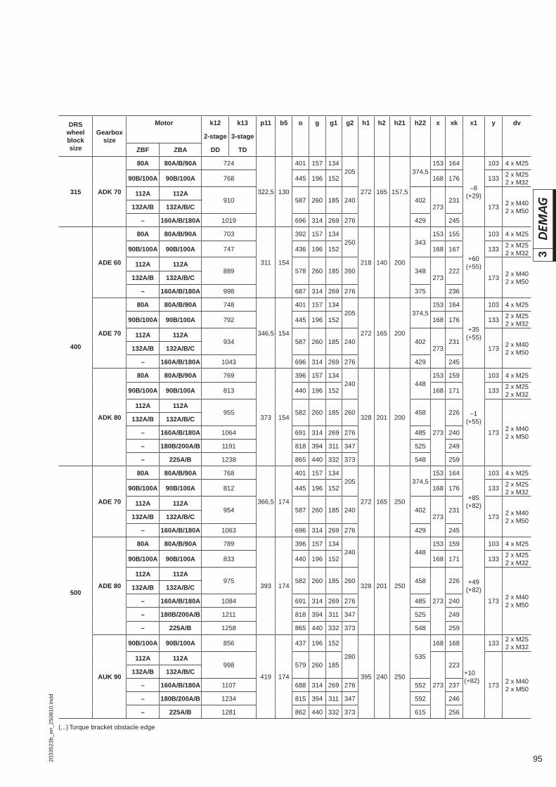
952033
523b
_en_
2508
10.in
dd
3
(...) Torque bracket obstacle edge
DRS wheel block size
Gearbox size
Motor k12 k13 p11 b5 o g g1 g2 h1 h2 h21 h22 x xk x1 y dv
2-stage 3-stage
ZBF ZBA DD TD
315 ADK 70
80A 80A/B/90A 724
322,5 130
401 157 134205
272 165 157,5
374,5153 164
–8(+29)
103 4 x M25
90B/100A 90B/100A 768 445 196 152 168 176 133 2 x M252 x M32
112A 112A910 587 260 185 240 402
273231
173 2 x M402 x M50132A/B 132A/B/C
– 160A/B/180A 1019 696 314 269 276 429 245
400
ADE 60
80A 80A/B/90A 703
311 154
392 157 134250
218 140 200
343153 155
+60(+55)
103 4 x M25
90B/100A 90B/100A 747 436 196 152 168 167 133 2 x M252 x M32
112A 112A889 578 260 185 260 348
273222
173 2 x M402 x M50132A/B 132A/B/C
– 160A/B/180A 998 687 314 269 276 375 236
ADE 70
80A 80A/B/90A 748
346,5 154
401 157 134205
272 165 200
374,5153 164
+35(+55)
103 4 x M25
90B/100A 90B/100A 792 445 196 152 168 176 133 2 x M252 x M32
112A 112A934 587 260 185 240 402
273231
173 2 x M402 x M50132A/B 132A/B/C
– 160A/B/180A 1043 696 314 269 276 429 245
ADK 80
80A 80A/B/90A 769
373 154
396 157 134240
328 201 200
448153 159
–1(+55)
103 4 x M25
90B/100A 90B/100A 813 440 196 152 168 171 133 2 x M252 x M32
112A 112A955 582 260 185 260 458
273
226
173 2 x M402 x M50
132A/B 132A/B/C
– 160A/B/180A 1064 691 314 269 276 485 240
– 180B/200A/B 1191 818 394 311 347 525 249
– 225A/B 1238 865 440 332 373 548 259
500
ADE 70
80A 80A/B/90A 768
366,5 174
401 157 134205
272 165 250
374,5153 164
+85(+82)
103 4 x M25
90B/100A 90B/100A 812 445 196 152 168 176 133 2 x M252 x M32
112A 112A954 587 260 185 240 402
273231
173 2 x M402 x M50132A/B 132A/B/C
– 160A/B/180A 1063 696 314 269 276 429 245
ADE 80
80A 80A/B/90A 789
393 174
396 157 134240
328 201 250
448153 159
+49(+82)
103 4 x M25
90B/100A 90B/100A 833 440 196 152 168 171 133 2 x M252 x M32
112A 112A975 582 260 185 260 458
273
226
173 2 x M402 x M50
132A/B 132A/B/C
– 160A/B/180A 1084 691 314 269 276 485 240
– 180B/200A/B 1211 818 394 311 347 525 249
– 225A/B 1258 865 440 332 373 548 259
AUK 90
90B/100A 90B/100A 856
419 174
437 196 152
280
395 240 250
535
168 168
+10(+82)
133 2 x M252 x M32
112A 112A998 579 260 185
273
223
173 2 x M402 x M50
132A/B 132A/B/C
– 160A/B/180A 1107 688 314 269 276 552 237
– 180B/200A/B 1234 815 394 311 347 592 246
– 225A/B 1281 862 440 332 373 615 256

96 2033
523b
_en_
2508
10.in
dd
3
3.19 Dimensions of travel drive with angular geared motor, direct input3.19.1 DRS 112 – 200 wheel block with angular gearbox and ZBF/ZBA motor
(...) Torque bracket obstacle edge
DRS wheel block size
Gearbox size
Motor k12 q12 b5 b6 b7 o g g1 h1 h21 h22 x xk x1 y dv
ZBF ZBA
112
WU. 10 63A/71A 63A/B/71A/B 489
138 81 198207 351 140 124
21,3 56 101
153
157 –9(–18)
103
4 x M20
80A 80A/B/90A 545 215 407 157 134 170 4 x M25
WU. 20
63A/71A 63A/B/71A/B 505
153,5 81 218
216 351 140 124
24,5 56110
157
–24
4 x M20
80A 80A/B/90A 561 225 407 157 134 170 4 x M25
90B/100A 90B/100A/B 606 244 452 196 152 123 168 183 133 2 x M252 x M32
125
WU. 10 63A/71A 63A/B/71A/B 489
138 87 204215 351 140 124
21,3 62,5 101
153
157 -3(–13)
103
4 x M20
80A 80A/B/90A 545 223 407 157 134 170 4 x M25
WU. 20
63A/71A 63A/B/71A/B 505
153,5 87 224
224 351 140 124
24,5 62,5110
157
–18
4 x M20
80A 80A/B/90A 561 233 407 157 134 170 4 x M25
90B/100A 90B/100A/B 606 252 452 196 152 123 168 183 133 2 x M252 x M32
WU. 30
63A/71A 63A/B/71A/B 525
174 88 245
234 351 140 124
27,5 62,5
104153
157
–28103
4 x M20
80A 80A/B/90A 581 243 407 157 134 106 170 4 x M25
90B/100A 90B/100A/B 626 262 452 196 152 126 168 183 133 2 x M252 x M32
160
WU. 20
63A/71A 63A/B/71A/B 505
153,5 103 240
241 351 140 124
24,5 80110 153
157
0(–2)
1034 x M20
80A 80A/B/90A 561 250 407 157 134 170 4 x M25
90B/100A 90B/100A/B 606 269 452 196 152 123 168 183 133 2 x M252 x M32
WU. 30
63A/71A 63A/B/71A/B 525
174 104 261
252 351 140 124
27,5 80
104153
157
–10103
4 x M20
80A 80A/B/90A 581 260 407 157 134 106 170 4 x M25
90B/100A 90B/100A/B 626 279 452 196 152 126 168 183 133 2 x M252 x M32
WU. 40
63A/71A 63A/B/71A/B 545
194 104 290,5
267 351 140 124
28,6 80
112 153157
–25
1034 x M20
80A 80A/B/90A 601 274 407 157 134 170 4 x M25
90B/100A 90B/100A/B 646 294 452 196 152 127 168 183 133 2 x M252 x M32
112A 112A788 326 594 260 185 159 273 238 173 2 x M32
2 x M40132A/B 132A/B/C
200 WU. 30
63A/71A 63A/B/71A/B 525
174 114 271
261 351 140 124
27,5 100
104153
157
+10(-5)
1034 x M20
80A 80A/B/90A 581 270 407 157 134 106 170 4 x M25
90B/100A 90B/100A/B 626 289 452 196 152 126 168 183 133 2 x M322 x M40
41673844.eps
W 10 – W 50 2-stage direct input
For travel wheel types E, C and F see section 3.1
3.19.1.1 DRS 112 – 200 with W 10 – W 50, 2-stage

972033
523b
_en_
2508
10.in
dd
3
(...) Torque bracket obstacle edge
DRS wheel block size
Gearbox size
Motor k12 q12 b5 b6 b7 o g g1 h1 h21 h22 x xk x1 y dv
ZBF ZBA
200
WU. 40
63A/71A 63A/B/71A/B 545
194 114 300,5
276 351 140 124
28,6 100
112 153157
–5
1034 x M20
80A 80A/B/90A 601 284 407 157 134 170 4 x M25
90B/100A 90B/100A/B 646 304 452 196 152 127 168 183 133 2 x M252 x M32
112A 112A788 336 594 260 185 159 273 238 173 2 x M32
2 x M40132A/B 132A/B/C
WU. 50
80A 80A/B/90A 634
227 114 325,5
316 407 157 134
33,3 100
136 153 170
-20
4 x M25
90B/100A 90B/100A/B 679 348 452 196 152 139 168 183 133 2 x M252 x M32
112A 112A821 375 594 260 185 163 273 238 173 2 x M32
2 x M40132A/B 132A/B/C
41674044.eps
W 20 – W 50 3-stage direct input
For travel wheel types E, C and F see section 3.1
DRS wheel block size
Gearbox size
Motor k13 q13 b5 b6 b7 o g g1 h1 h21 h22 x xk x1 y dv
ZBF ZBA
112 WU. 20 63A/71A 63A/B/71A/B 567
215,5 81 218216 351 140 124
24,5 56 110
153
157–24
103
4 x M20
80A 80A/B/90A 623 225 407 157 134 170 4 x M25
125
WU. 20 63A/71A 63A/B/71A/B 567
215,5 87 224224 351 140 124
24,5 62,5 110157
–184 x M20
80A 80A/B/90A 623 233 407 157 134 170 4 x M25
WU. 30 63A/71A 63A/B/71A/B 587
236 88 245234 351 140 124
27,5 62,5104 157
–284 x M20
80A 80A/B/90A 643 243 407 157 134 106 170 4 x M25
160
WU. 2063A/71A 63A/B/71A/B 567
215,5 103 240241 351 140 124
24,5 80 110157 0
(–2)4 x M20
80A 80A/B/90A 623 250 407 157 134 170 4 x M25
WU. 30 63A/71A 63A/B/71A/B 567
236 104 261252 351 140 124
27,5 80104 157
–104 x M20
80A 80A/B/90A 623 260 407 157 134 106 170 4 x M25
WU. 4063A/71A 63A/B/71A/B 615
264 104 290,5267 351 140 124
28,6 80 112157
–254 x M20
80A 80A/B/90A 671 274 407 157 134 170 4 x M25
200
WU. 30 63A/71A 63A/B/71A/B 567
236 114 271261 351 140 124
27,5 100104 157 +10
(-5)4 x M20
80A 80A/B/90A 623 270 407 157 134 106 170 4 x M25
WU. 4063A/71A 63A/B/71A/B 615
264 114 300,5276 351 140 124
28,6 100 112157
–54 x M20
80A 80A/B/90A 671 284 407 157 134 1704 x M25
WU. 5080A 80A/B/90A 704
279 114 325,5297 407 157 134
33,3 100 136170
–2090B/100A 90B/100A/B 749 316 452 196 152 168 183 133 2 x M25
2 x M32
3.19.1.2 DRS 112 – 200 with W 20 – W 50 3-stage direct input

98 2033
523b
_en_
2508
10.in
dd
3
42200044.epsFor travel wheel types E, C and F see section 3.1
W 60 3-stage direct input
DRS wheel block size
Gearbox size
Motor k13 q13 b5 b6 b7 o g g1 h1 h21 h22 x xk x1 y dv
ZBF ZBA
200 WU. 60
80A 80A/B/90A 604
203 98 331,5
292 401 157 134
11,5 100 138
153 164
–105
103 4 x M25
90B/100A 90B/100A/B 648 311 445 196 152 168 176 133 2 x M252 x M32
112A 112A790 343 587 260 185
273231
173
2 x M322 x M40132A/B 132A/B/C
– 160A/B/180A 899 370 696 314 269 245 2 x M402 x M50
W 60 3-stage direct inputNote: This model offers greater ground clearance
42200045.epsFor travel wheel types E, C and F see section 3.1
DRS wheel block size
Gearbox size
Motor k13 q13 b5 b6 b7 o g g1 h1 h21 h23 x xk x11 y dv
ZBF ZBA
200 WU. 60
80A 80A/B/90A 604
203 98 331,5
292 401 157 134
11,5 100 205
153 164 –7 103 4 x M25
90B/100A 90B/100A/B 648 311 445 196 152 168 176 –7 133 2 x M252 x M32
112A 112A790 343 587 260 185
273231 –18,5
173
2 x M322 x M40132A/B 132A/B/C
– 160A/B/180A 899 370 696 314 269 245 –45,5 2 x M402 x M50
3.19.1.3 DRS 200 with W 60, 3-stage

992033
523b
_en_
2508
10.in
dd
3
42200144.eps
W 60 4-stage direct input
For travel wheel types E, C and F see section 3.1
DRS wheel block size
Gearbox size
Motor k14 q14 b5 b6 b7 o g g1 h1 h21 h22 x xk x1 y dv
ZBF ZBA
200 WU. 60
63A/71A 63A/B/71A/B 658
307 98 331,5
283 351 140 124
54,5 100 138153
157
–105103
4 x M20
80A 80A/B/90A 714 292 407 157 134 170 4 x M25
90B/100A 90B/100A/B 759 311 452 196 152 168 183 133 2 x M252 x M32
W 60 4-stage direct inputNote: This model offers greater ground clearance
42200145.epsFor travel wheel types E, C and F see section 3.1
DRS wheel block size
Gearbox size
Motor k14 q14 b5 b6 b7 o g g1 h1 h21 h23 x xk x11 y dv
ZBF ZBA
200 WU. 60
63A/71A 63A/B/71A/B 658
307 98 331,5
283 351 140 124
54,5 100 205153
157
-7103
4 x M20
80A 80A/B/90A 714 292 407 157 134 170 4 x M25
90B/100A 90B/100A/B 759 311 452 196 152 168 183 133 2 x M252 x M32
3.19.1.4 DRS 200 with W 60, 4-stage

100 2033
523b
_en_
2508
10.in
dd
3
3.19.2 DRS 250 – 500 wheel block with angular gearbox and ZBF/ZBA motor
W 40 – W 50 2-stage direct input
For travel wheel types E, C and F see section 3.2
(...) Torque bracket obstacle edge
42096844.eps
DRS wheel block size
Gearboxsize
Motor k12 q12 b5 b6 b7 o g g1 h1 h21 h22 x xk x1 y dv
ZBF ZBA
250
WU. 40
63A/71A 63A/B/71A/B 545
194 108 294,5
271 351 140 124
28,6 125 156
153157
+20
1034 x M20
80A 80A/B/90A 601 280 407 157 134 170 4 x M25
90B/100A 90B/100A/B 646 299 452 196 152 168 183 133 2 x M252 x M32
112A 112A788 331 594 260 185 273 238 173 2 x M32
2 x M40132A/B 132A/B/C
WU. 50
80A 80A/B/90A 634
227 108 319,5
293 407 157 134
33,3 125 156
153 170
+5(+20)
103 4 x M25
90B/100A 90B/100A/B 679 312 452 196 152 168 183 133 2 x M252 x M32
112A 112A821 344 594 260 185
273238
173
2 x M322 x M40132A/B 132A/B/C
– 160A/B/180A 930 371 703 314 269 252 2 x M402 x M50
315 WU. 50
80A 80A/B/90A 634
277 130 341,5
319 407 157 134
33,3 157,5 192
153 170
+37(+29)
103 4 x M25
90B/100A 90B/100A/B 679 332 452 196 152 168 183 133 2 x M252 x M32
112A 112A821 364 594 260 185
273238
173
2 x M322 x M40132A/B 132A/B/C
– 160A/B/180A 930 372 703 314 269 252 2 x M402 x M50
3.19.2.1 DRS 250 – 315 with W 40 – W 50 2-stage direct input

1012033
523b
_en_
2508
10.in
dd
3
W 40 – W 50 2-stage direct inputNote: This model offers greater ground clearance
42096845.epsFor travel wheel types E, C and F see section 3.2
DRS wheel block size
Gearboxsize
Motor k12 q12 b5 b6 b7 o g g1 h1 h21 h23 x xk x11 y dv
ZBF ZBA
250
WU. 40
63A/71A 63A/B/71A/B 545
194 108 294,5
271 351 140 124
28,6 125 156
153157 +21
1034 x M20
80A 80A/B/90A 601 280 407 157 134 170 +17 4 x M25
90B/100A 90B/100A/B 646 299 452 196 152 168 183 –2 133 2 x M252 x M32
112A 112A788 331 594 260 185 273 238 –34 173 2 x M32
2 x M40132A/B 132A/B/C
WU. 50
80A 80A/B/90A 634
227 108 319,5
293 407 157 134
33,3 125 156
153 170–12
103 4 x M25
90B/100A 90B/100A/B 679 312 452 196 152 168 183 133 2 x M252 x M32
112A 112A821 344 594 260 185
273238 –39
173
2 x M322 x M40132A/B 132A/B/C
– 160A/B/180A 930 371 703 314 269 252 –66 2 x M402 x M50
315 WU. 50
80A 80A/B/90A 634
277 130 341,5
319 407 157 134
33,3 157,5 192
153 170+21
103 4 x M25
90B/100A 90B/100A/B 679 332 452 196 152 168 183 133 2 x M252 x M32
112A 112A821 364 594 260 185
273238 –6
173
2 x M322 x M40132A/B 132A/B/C
– 160A/B/180A 930 372 703 314 269 252 –33 2 x M402 x M50

102 2033
523b
_en_
2508
10.in
dd
3
(...) Torque bracket obstacle edge
42096944.eps
W 40 – W 50 3-stage direct input
For travel wheel types E, C and F see section 3.2
DRS wheel block size
Gearbox size
Motor k13 q13 b5 b6 b7 o g g1 h1 h21 h22 x xk x1 y dv
ZBF ZBA
250WU. 40
63A/71A 63A/B/71A/B 615264 108 294,5
271 351 140 12428,6
125 156 153
157+20
103
4 x M20
80A 80A/B/90A 671 280407 157 134 170 4 x M25
WU. 50 80A 80A/B/90A 704 297 108 319,5 293 33,3 +5(+20)
315 WU. 50
80A 80A/B/90A 704
297 130 341,5
319 407 157 134
33,3 157,5 192
153 170
+37(+29)
103 4 x M25
90B/100A 90B/100A/B 749 332 452 196 152 168 183 133 2 x M252 x M32
112A 112A891 364 594 260 185
273238
173
2 x M322 x M40132A/B 132A/B/C
– 160A/B/180A 1000 372 703 314 269 252 2 x M402 x M50
3.19.2.2 DRS 250 – 315 with W 40 – W 50 3-stage direct input
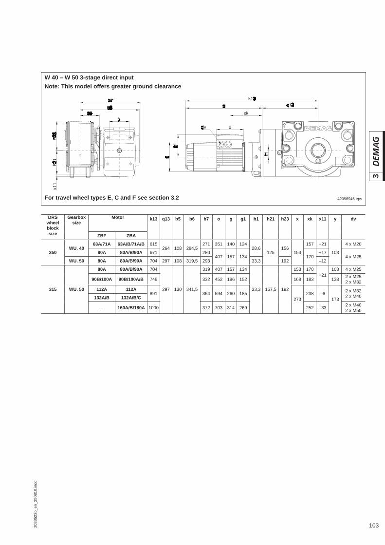
1032033
523b
_en_
2508
10.in
dd
3
DRS wheel block size
Gearbox size
Motor k13 q13 b5 b6 b7 o g g1 h1 h21 h23 x xk x11 y dv
ZBF ZBA
250WU. 40
63A/71A 63A/B/71A/B 615264 108 294,5
271 351 140 12428,6
125156
153
157 +21
103
4 x M20
80A 80A/B/90A 671 280407 157 134 170
+174 x M25
WU. 50 80A 80A/B/90A 704 297 108 319,5 293 33,3 192 –12
315 WU. 50
80A 80A/B/90A 704
297 130 341,5
319 407 157 134
33,3 157,5 192
153 170+21
103 4 x M25
90B/100A 90B/100A/B 749 332 452 196 152 168 183 133 2 x M252 x M32
112A 112A891 364 594 260 185
273238 –6
173
2 x M322 x M40132A/B 132A/B/C
– 160A/B/180A 1000 372 703 314 269 252 –33 2 x M402 x M50
W 40 – W 50 3-stage direct inputNote: This model offers greater ground clearance
42096945.epsFor travel wheel types E, C and F see section 3.2

104 2033
523b
_en_
2508
10.in
dd
3
41674244.epsFor travel wheel types E, C and F see section 3.2
W 60 – W 100 3-stage direct input
DRS wheel block size
Gearbox size
Motor k13 q13 b5 b6 b7 o g g1 h1 h21 h22 x xk x1 y dv
ZBF ZBA
250
WU. 60
80A 80A/B/90A 604
203 108 341,5
302 401 157 134
11,5 125 156
153 164
–80
103 4 x M25
90B/100A 90B/100A/B 648 321 445 196 152 168 176 133 2 x M252 x M32
112A 112A790 353 587 260 185
273231
173
2 x M322 x M40132A/B 132A/B/C
– 160A/B/180A 899 380 696 314 269 245 2 x M402 x M50
WU. 70
80A 80A/B/90A 627
231 108 382
322 396 157 134
6 125 156
153 159
–120
103 4 x M25
90B/100A 90B/100A/B 671 341 440 196 152 168 171 133 2 x M252 x M32
112A 112A813 373 582 260 185
273
226
173
2 x M322 x M40132A/B 132A/B/C
– 160A/B/180A 922 400 691 314 269 2402 x M402 x M50– 180B/200A/B 1049 440 818 394 311 249
– 225A/B 1096 463 865 440 332 259
315
WU. 60
80A 80A/B/90A 604
203 130 363,5
324 401 157 134
11,5 157,5 193
153 164
–48
103 4 x M25
90B/100A 90B/100A/B 648 343 445 196 152 168 176 133 2 x M252 x M32
112A 112A790 375 587 260 185
273231
173
2 x M322 x M40132A/B 132A/B/C
– 160A/B/180A 899 383 696 314 269 245 2 x M402 x M50
WU. 70
80A 80A/B/90A 627
231 130 404
344 396 157 134
6 157,5 193
153 159
–88
103 4 x M25
90B/100A 90B/100A/B 671 363 440 196 152 168 171 133 2 x M252 x M32
112A 112A813 395 582 260 185
273
226
173
2 x M322 x M40132A/B 132A/B/C
– 160A/B/180A 922 422 691 314 269 2402 x M402 x M50– 180B/200A 1049 462 818 394 311 249
– 225A/B 1096 485 865 440 332 259
3.19.2.3 DRS 250 – 500 with W 60 – W 100 3-stage direct input

1052033
523b
_en_
2508
10.in
dd
3
DRS wheel block size
Gearbox size
Motor k13 q13 b5 b6 b7 o g g1 h1 h21 h22 x xk x1 y dv
ZBF ZBA
80A 80A/B/90A 646
250 130 409
346 396 157 134
32 157,5 193
153 159
–118
103 4 x M25
90B/100A 90B/100A/B 690 366 440 196 152 168 171 133 2 x M252 x M32
112A 112A832 398 582 260 185
273
226
173
2 x M322 x M40315 WU. 80 132A/B 132A/B/C
– 160A/B/180A 941 425 691 314 269 2402 x M402 x M50– 180B/200A 1068 465 818 394 311 249
– 225A/B 1115 488 865 440 332 259
400
WU. 70
80A 80A/B/90A 627
231 154 428
368 396 157 134
6 200 240
153 159
– 45
103 4 x M25
90B/100A 90B/100A/B 671 387 440 196 152 168 171 133 2 x M252 x M32
112A 112A813 419 582 260 185
273
226
173
2 x M322 x M40132A/B 132A/B/C
– 160A/B/180A 922 446 691 314 269 2402 x M402 x M50– 180B/200A 1049 486 818 394 311 249
– 225A/B 1096 509 865 440 332 259
WU. 80
80A 80A/B/90A 646
250 154 433
370 396 157 134
32 200 240
153 159
–75
103 4 x M25
90B/100A 90B/100A/B 690 390 440 196 152 168 171 133 2 x M252 x M32
112A 112A832 422 582 260 185
273
226
173
2 x M322 x M40132A/B 132A/B/C
– 160A/B/180A 941 449 691 314 269 2402 x M402 x M50– 180B/200A 1068 489 818 394 311 249
– 225A/B 1115 512 865 440 332 259
WU. 90
90B/100A 90B/100A/B 728
291 154 469
407 437 196 152
32 200 240
168 168
–115
133 2 x M252 x M32
112A 112A870 439 579 260 185
273
223
173
2 x M322 x M40132A/B 132A/B/C
– 160A/B/180A 979 466 688 314 269 2372 x M402 x M50– 180B/200A 1106 506 815 394 311 246
– 225A/B 1153 529 862 440 332 256
500
WU. 80
80A 80A/B/90A 646
250 174 453
390 396 157 134
32 250 316
153 159
–25
103 4 x M25
90B/100A 90B/100A/B 690 410 440 196 152 168 171 133 2 x M252 x M32
112A 112A832 442 582 260 185
273
226
173
2 x M322 x M40132A/B 132A/B/C
– 160A/B/180A 941 469 691 314 269 2402 x M402 x M50– 180B/200A 1068 509 818 394 311 249
– 225A/B 1115 532 865 440 332 259
WU. 90
90B/100A 90B/100A/B 728
291 174 489
427 437 196 152
32 250 316
168 168
–65
133 2 x M252 x M32
112A 112A870 459 579 260 185
273
223
173
2 x M322 x M40132A/B 132A/B/C
– 160A/B/180A 979 486 688 314 269 2372 x M402 x M50– 180B/200A 1106 526 815 394 311 246
– 225A/B 1153 549 862 440 332 256
WU. 100
112A 112A931
352 174 559
494 579 260 185
44 250 316 273
223
–140 173
2 x M322 x M40132A/B 132A/B/C
– 160A/B/180A 1040 521 688 314 269 2372 x M402 x M50– 180B/200A 1167 561 815 394 311 246
– 225A/B 1214 584 862 440 332 256

106 2033
523b
_en_
2508
10.in
dd
3
W 60 – W 100 3-stage direct inputNote: This model offers greater ground clearance
41674245.epsFor travel wheel types E, C and F see section 3.2
DRS wheel block size
Gearbox size
Motor k13 q13 b5 b6 b7 o g g1 h1 h21 h23 x xk x11 y dv
ZBF ZBA
250
WU. 60
80A 80A/B/90A 604
203 108 331,5
302 401 157 134
11,5 125 205
153 164+18
103 4 x M25
90B/100A 90B/100A/B 648 321 445 196 152 168 176 133 2 x M252 x M32
112A 112A790 353 587 260 185
273231 +6,5
173
2 x M322 x M40132A/B 132A/B/C
– 160A/B/180A 899 380 696 314 269 245 -20,5 2 x M402 x M50
WU. 70
80A 80A/B/90A 627
231 108 382
322 396 157 134
6 125 245
153 159-3
103 4 x M25
90B/100A 90B/100A/B 671 341 440 196 152 168 171 133 2 x M252 x M32
112A 112A813 373 582 260 185
273
226 -3
173
2 x M322 x M40132A/B 132A/B/C
– 160A/B/180A 922 400 691 314 269 240 -262 x M402 x M50– 180B/200A/B 1049 440 818 394 311 249 -66
– 225A/B 1096 463 865 440 332 259 -89
315
WU. 60
80A 80A/B/90A 604
203 130 363,5
324 401 157 134
11,5 158 205
153 164
+30
103 4 x M25
90B/100A 90B/100A/B 648 343 445 196 152 168 176 133 2 x M252 x M32
112A 112A790 375 587 260 185
273231
173
2 x M322 x M40132A/B 132A/B/C
– 160A/B/180A 899 383 696 314 269 245 +12 2 x M402 x M50
WU. 70
80A 80A/B/90A 627
231 130 404
344 396 157 134
6 158 245
153 159
+29
103 4 x M25
90B/100A 90B/100A/B 671 363 440 196 152 168 171 133 2 x M252 x M32
112A 112A813 395 582 260 185
273
226
173
2 x M322 x M40132A/B 132A/B/C
– 160A/B/180A 922 422 691 314 269 240 +6,52 x M402 x M50– 180B/200A/B 1049 462 818 394 311 249 -33,5
– 225A/B 1096 485 865 440 332 259 -56,5
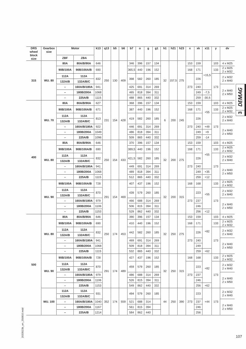
1072033
523b
_en_
2508
10.in
dd
3
DRS wheel block size
Gearbox size
Motor k13 q13 b5 b6 b7 o g g1 h1 h21 h23 x xk x11 y dv
ZBF ZBA
315 WU. 80
80A 80A/B/90A 646
250 130 409
346 396 157 134
32 157,5 275
153 159
+15,5
103 4 x M25
90B/100A 90B/100A/B 690 365,5 440 196 152 168 171 133 2 x M252 x M32
112A 112A832 398 582 260 185
273
226
173
2 x M322 x M40132A/B 132A/B/C
– 160A/B/180A 941 425 691 314 269 2402 x M402 x M50– 180B/200A 1068 465 818 394 311 249 -7,5
– 225A/B 1115 488 865 440 332 259 -30,5
400
WU. 70
80A 80A/B/90A 627
231 154 428
368 396 157 134
6 200 245
153 159
+55
103 4 x M25
90B/100A 90B/100A/B 671 387 440 196 152 168 171 133 2 x M252 x M32
112A 112A813 419 582 260 185
273
226
173
2 x M322 x M40132A/B 132A/B/C
– 160A/B/180A 922 446 691 314 269 240 +492 x M402 x M50– 180B/200A 1049 486 818 394 311 249 +9
– 225A/B 1096 509 865 440 332 259 -14
WU. 80
80A 80A/B/90A 646
250 154 433
370 396 157 134
32 200 275
153 159
+55
103 4 x M25
90B/100A 90B/100A/B 690 389,5 440 196 152 168 171 133 2 x M252 x M32
112A 112A832 421,5 582 260 185
273
226
173
2 x M322 x M40132A/B 132A/B/C
– 160A/B/180A 941 449 691 314 269 2402 x M402 x M50– 180B/200A 1068 489 818 394 311 249 +35
– 225A/B 1115 512 865 440 332 259 +12
WU. 90
90B/100A 90B/100A/B 728
291 154 469
407 437 196 152
32 200 315
168 168
+55
133 2 x M252 x M32
112A 112A870 439 579 260 185
273
223
173
2 x M322 x M40132A/B 132A/B/C
– 160A/B/180A 979 466 688 314 269 2372 x M402 x M50– 180B/200A 1106 506 815 394 311 246
– 225A/B 1153 529 862 440 332 256 +12
500
WU. 80
80A 80A/B/90A 646
250 174 453
390 396 157 134
32 250 275
153 159
+82
103 4 x M25
90B/100A 90B/100A/B 690 410 440 196 152 168 171 133 2 x M252 x M32
112A 112A832 442 582 260 185
273
226
173
2 x M322 x M40132A/B 132A/B/C
– 160A/B/180A 941 469 691 314 269 2402 x M402 x M50– 180B/200A 1068 509 818 394 311 249
– 225A/B 1115 532 865 440 332 259 +62
WU. 90
90B/100A 90B/100A/B 728
291 174 489
427 437 196 152
32 250 315
168 168
+82
133 2 x M252 x M32
112A 112A870 459 579 260 185
273
223
173
2 x M322 x M40132A/B 132A/B/C
– 160A/B/180A 979 486 688 314 269 2372 x M402 x M50– 180B/200A 1106 526 815 394 311 246
– 225A/B 1153 549 862 440 332 256 +62
WU. 100
112A 112A931
352 174 559
494 579 260 185
44 250 390 273
223
+44 173
2 x M322 x M40132A/B 132A/B/C
– 160A/B/180A 1040 521 688 314 2372 x M402 x M50– 180B/200A 1167 561 815 394 246
– 225A/B 1214 584 862 440 256
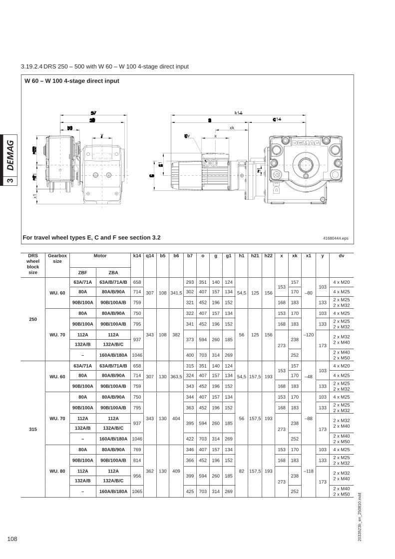
108 2033
523b
_en_
2508
10.in
dd
3
41680444.eps
W 60 – W 100 4-stage direct input
For travel wheel types E, C and F see section 3.2
DRS wheel block size
Gearbox size
Motor k14 q14 b5 b6 b7 o g g1 h1 h21 h22 x xk x1 y dv
ZBF ZBA
250
WU. 60
63A/71A 63A/B/71A/B 658
307 108 341,5
293 351 140 124
54,5 125 156153
157
–80103
4 x M20
80A 80A/B/90A 714 302 407 157 134 170 4 x M25
90B/100A 90B/100A/B 759 321 452 196 152 168 183 133 2 x M252 x M32
WU. 70
80A 80A/B/90A 750
343 108 382
322 407 157 134
56 125 156
153 170
–120
103 4 x M25
90B/100A 90B/100A/B 795 341 452 196 152 168 183 133 2 x M252 x M32
112A 112A937 373 594 260 185
273238
173
2 x M322 x M40132A/B 132A/B/C
– 160A/B/180A 1046 400 703 314 269 252 2 x M402 x M50
315
WU. 60
63A/71A 63A/B/71A/B 658
307 130 363,5
315 351 140 124
54,5 157,5 193153
157
–48103
4 x M20
80A 80A/B/90A 714 324 407 157 134 170 4 x M25
90B/100A 90B/100A/B 759 343 452 196 152 168 183 133 2 x M252 x M32
WU. 70
80A 80A/B/90A 750
343 130 404
344 407 157 134
56 157,5 193
153 170
–88
103 4 x M25
90B/100A 90B/100A/B 795 363 452 196 152 168 183 133 2 x M252 x M32
112A 112A937 395 594 260 185
273238
173
2 x M322 x M40132A/B 132A/B/C
– 160A/B/180A 1046 422 703 314 269 252 2 x M402 x M50
WU. 80
80A 80A/B/90A 769
362 130 409
346 407 157 134
82 157,5 193
153 170
–118
103 4 x M25
90B/100A 90B/100A/B 814 366 452 196 152 168 183 133 2 x M252 x M32
112A 112A956 399 594 260 185
273238
173
2 x M322 x M40132A/B 132A/B/C
– 160A/B/180A 1065 425 703 314 269 252 2 x M402 x M50
3.19.2.4 DRS 250 – 500 with W 60 – W 100 4-stage direct input

1092033
523b
_en_
2508
10.in
dd
3
DRS wheel block size
Gearbox size
Motor k14 q14 b5 b6 b7 o g g1 h1 h21 h22 x xk x1 y dv
ZBF ZBA
400
WU. 70
80A 80A/B/90A 750
343 154 428
368 401 157 134
56 200 240
153 170
–45
103 4 x M25
90B/100A 90B/100A/B 795 387 452 196 152 168 183 133 2 x M252 x M32
112A 112A937 419 594 260 185
273238
173
2 x M322 x M40132A/B 132A/B/C
– 160A/B/180A 1046 446 703 314 269 252 2 x M402 x M50
WU. 80
80A 80A/B/90A 769
362 154 433
370 407 157 134
82 200 240
153 170
–75
103 4 x M25
90B/100A 90B/100A/B 814 390 452 196 152 168 183 133 2 x M252 x M32
112A 112A956 421,5 594 260 185
273238
173
2 x M322 x M40132A/B 132A/B/C
– 160A/B/180A 1065 449 703 314 269 252 2 x M402 x M50
WU. 90
80A 80A/B/90A 821
420 154 469
388 401 157 134
93 200 240
153 164
–115
103 4 x M25
90B/100A 90B/100A/B 865 407 445 196 152 168 176 133 2 x M252 x M32
112A 112A1014 439 587 260 185
273231
173
2 x M322 x M40132A/B 132A/B/C
– 160A/B/180A 1116 466 696 314 269 245 2 x M402 x M50
500
WU. 80
80A 80A/B/90A 769
362 174 453
390 407 157 134
82 250 316
153 170
–25
103 4 x M25
90B/100A 90B/100A/B 814 410 452 196 152 168 183 133 2 x M252 x M32
112A 112A956 442 594 260 185
273238
173
2 x M322 x M40132A/B 132A/B/C
– 160A/B/180A 1065 469 703 314 269 252 2 x M402 x M50
WU. 90
80A 80A/B/90A 821
420 174 489
408 401 157 134
93 250 316
153 164
–65
103 4 x M25
90B/100A 90B/100A/B 865 427 445 196 152 168 176 133 2 x M252 x M32
112A 112A1014 459 587 260 185
273231
173
2 x M322 x M40132A/B 132A/B/C
– 160A/B/180A 1118 486 696 314 269 245 2 x M402 x M50
WU. 100
80A 80A/B/90A 886
490 174 559
443 396 157 134
122 250 316
153 159
–140
103 4 x M25
90B/100A 90B/100A/B 930 462 440 196 152 168 171 133 2 x M252 x M32
112A 112A1072 494 582 260 185
273
226
173
2 x M322 x M40132A/B 132A/B/C
– 160A/B/180A 1181 521 691 314 269 2402 x M402 x M50– 180B/200A 1308 561 818 394 311 249
– 225A/B 1355 584 865 440 332 259

110 2033
523b
_en_
2508
10.in
dd
3
W 60 – W 100 4-stage direct inputNote: This model offers greater ground clearance
41680445.epsFor travel wheel types E, C and F see section 3.2
DRS wheel block size
Gearbox size
Motor k14 q14 b5 b6 b7 o g g1 h1 h21 h23 x xk x11 y dv
ZBF ZBA
250
WU. 60
63A/71A 63A/B/71A/B 658
307 108 341,5
293 351 140 124
54,5 125 205153
157
+18103
4 x M20
80A 80A/B/90A 714 302 407 157 134 170 4 x M25
90B/100A 90/100A/B 759 321 452 196 152 168 183 133 2 x M252 x M32
WU. 70
80A 80A/B/90A 750
343 108 382
322 407 157 134
56 125 245
153 170
-3
103 4 x M25
90B/100A 90/100A/B 795 341 452 196 152 168 183 133 2 x M252 x M32
112A 112A937 373 594 260 185
273238
173
2 x M322 x M40132A/B 132A/B/C
– 160A/B/180A 1046 400 703 314 269 252 2 x M402 x M50
315
WU. 60
63A/71A 63A/B/71A/B 658
307 130 363,5
315 351 140 124
54,5 157,5 205153
157
+30
1034 x M20
80A 80A/B/90A 714 324 407 157 134 170 4 x M25
90B/100A 90B/100A/B 759 343 452 196 152 168 183 133 2 x M252 x M32
WU. 70
80A 80A/B/90A 750
343 130 404
344 407 157 134
56 157,5 245
153 170 103 4 x M25
90B/100A 90B/100A/B 795 363 452 196 152 168 183 133 2 x M252 x M32
112A 112A937 395 594 260 185
273238
173
2 x M322 x M40132A/B 132A/B/C
– 160A/B/180A 1046 422 703 314 269 252 2 x M402 x M50
WU. 80
80A 80A/B/90A 769
362 130 409
346 407 157 134
82 157,5 275
153 170
+15,5
103 4 x M25
90B/100A 90B/100A/B 814 366 452 196 152 168 183 133 2 x M252 x M32
112A 112A956 398 594 260 185
273238
173
2 x M322 x M40132A/B 132A/B/C
– 160A/B/180A 1065 425 703 314 269 252 2 x M402 x M50
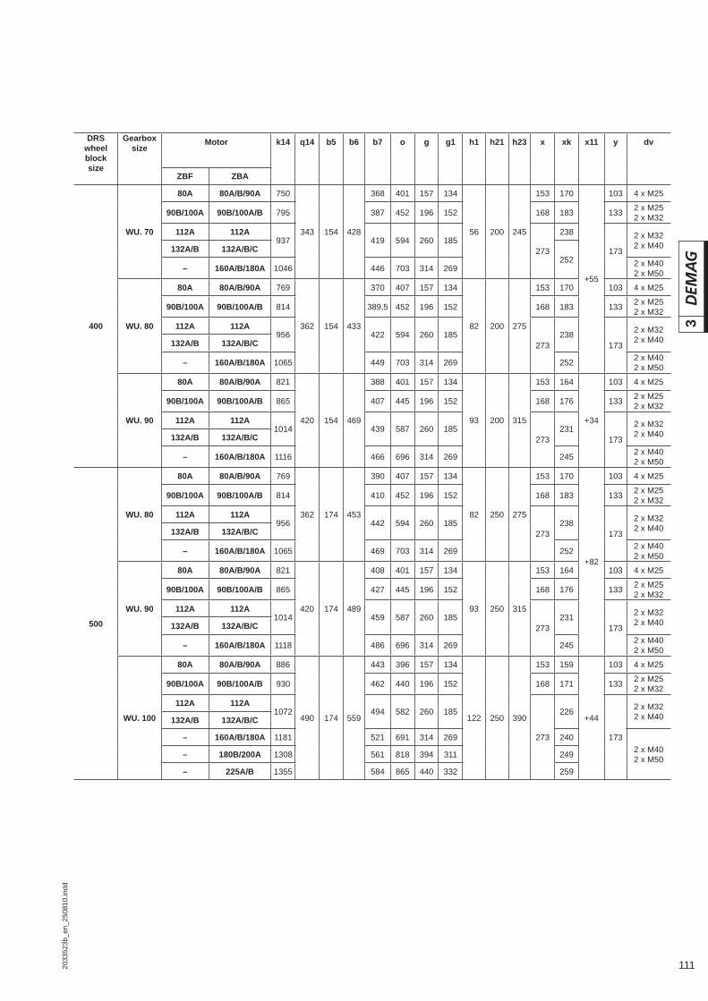
1112033
523b
_en_
2508
10.in
dd
3
DRS wheel block size
Gearbox size
Motor k14 q14 b5 b6 b7 o g g1 h1 h21 h23 x xk x11 y dv
ZBF ZBA
400
WU. 70
80A 80A/B/90A 750
343 154 428
368 401 157 134
56 200 245
153 170
+55
103 4 x M25
90B/100A 90B/100A/B 795 387 452 196 152 168 183 133 2 x M252 x M32
112A 112A937 419 594 260 185
273
238
173
2 x M322 x M40132A/B 132A/B/C
252– 160A/B/180A 1046 446 703 314 269 2 x M40
2 x M50
WU. 80
80A 80A/B/90A 769
362 154 433
370 407 157 134
82 200 275
153 170 103 4 x M25
90B/100A 90B/100A/B 814 389,5 452 196 152 168 183 133 2 x M252 x M32
112A 112A956 422 594 260 185
273238
173
2 x M322 x M40132A/B 132A/B/C
– 160A/B/180A 1065 449 703 314 269 252 2 x M402 x M50
WU. 90
80A 80A/B/90A 821
420 154 469
388 401 157 134
93 200 315
153 164
+34
103 4 x M25
90B/100A 90B/100A/B 865 407 445 196 152 168 176 133 2 x M252 x M32
112A 112A1014 439 587 260 185
273231
173
2 x M322 x M40132A/B 132A/B/C
– 160A/B/180A 1116 466 696 314 269 245 2 x M402 x M50
500
WU. 80
80A 80A/B/90A 769
362 174 453
390 407 157 134
82 250 275
153 170
+82
103 4 x M25
90B/100A 90B/100A/B 814 410 452 196 152 168 183 133 2 x M252 x M32
112A 112A956 442 594 260 185
273238
173
2 x M322 x M40132A/B 132A/B/C
– 160A/B/180A 1065 469 703 314 269 252 2 x M402 x M50
WU. 90
80A 80A/B/90A 821
420 174 489
408 401 157 134
93 250 315
153 164 103 4 x M25
90B/100A 90B/100A/B 865 427 445 196 152 168 176 133 2 x M252 x M32
112A 112A1014 459 587 260 185
273231
173
2 x M322 x M40132A/B 132A/B/C
– 160A/B/180A 1118 486 696 314 269 245 2 x M402 x M50
WU. 100
80A 80A/B/90A 886
490 174 559
443 396 157 134
122 250 390
153 159
+44
103 4 x M25
90B/100A 90B/100A/B 930 462 440 196 152 168 171 133 2 x M252 x M32
112A 112A1072 494 582 260 185
273
226
173
2 x M322 x M40132A/B 132A/B/C
– 160A/B/180A 1181 521 691 314 269 2402 x M402 x M50– 180B/200A 1308 561 818 394 311 249
– 225A/B 1355 584 865 440 332 259
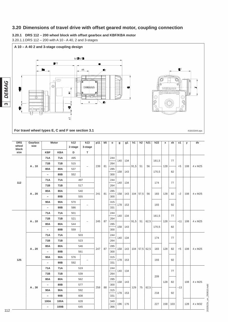
112 2033
523c
_en_
2508
10.in
dd
3
3.20 Dimensions of travel drive with offset geared motor, coupling connection3.20.1 DRS 112 – 200 wheel block with offset gearbox and KBF/KBA motor
41810344.eps
A 10 – A 40 2 and 3-stage coupling design
For travel wheel types E, C and F see section 3.1
DRS wheel block size
Gearbox size
Motor k12 k13 p11 b5 o g g1 h1 h2 h21 h22 x xk x1 y dv2-stage 3-stage
KBF KBA D T
112
A .. 10
71A 71A 495
– 239 81
244140 134
91,5 51 56
161,5
128
77
+5 108 4 x M2571B 71B 515 264
80A 80A 537 285158 143 170,5 82
– 80B 552 300
A .. 20
71A 71A 497
241 81
244140 134
104 57,5 56
174
128
77
–2 108 4 x M25
71B 71B 517 264
80A 80A 540 285158 143 183 82
– 80B 555 300
90A 90A 570–
315178 153 193 92
– 90B 586 331
125
A .. 10
71A 71A 501
– 245 87
244140 134
91,5 51 62,5
161,5
128
77
+11 108 4 x M2571B 71B 521 264
80A 80A 544 285158 143 170,5 82
– 80B 559 300
A .. 20
71A 71A 503
247 87
244140 134
104 57,5 62,5
174
128
77
+5 108 4 x M25
71B 71B 523 264
80A 80A 546 285158 143 183 82
– 80B 561 300
90A 90A 576–
315178 153 193 92
– 90B 592 331
A .. 30
71A 71A 519
259 88
244140 134
129 75 62,5
209
128
77
–13
108 4 x M25
71B 71B 539 264
80A 80A 562 285158 143 82
– 80B 577 300
90A 90A 592 315178 153 218 92
– 90B 608 331
100A 100A 628 349196 176 227 158 103 128 4 x M32
– 100B 645 366
3.20.1.1 DRS 112 – 200 with A 10 - A 40, 2 and 3-stages

1132033
523c
_en_
2508
10.in
dd
3
DRS wheel
block size
Gearboxsize
Motor k12 k13 p11 b5 o g g1 h1 h2 h21 h22 x xk x1 y dv
2-stage 3-stage
KBF KBA D T
160
A .. 20
71A 71A 519
263 103
244140 134
104 57,5 80
174
128
77
+22 108 4 x M25
71B 71B 539 264
80A 80A 563 285158 143 183 82
– 80B 577 300
90A 90A 592–
315178 153 193 92
– 90B 608 331
A .. 30
71A 71A 535
275 104
244140 134
129 75 80
209
128
77
+5
108 4 x M25
71B 71B 555 264
80A 80A 578 285158 143 82
– 80B 593 300
90A 90A 608 315178 153 218 92
– 90B 624 331
100A 100A 643 348196 176 227 158 103 128 4 x M32
– 100B 660 365
A .. 40
71A 71A 538
278 104
244140 134
148 90 80
228
128
77
–10
108 4 x M25
71B 71B 558 264
80A 80A 581 285158 143 82
– 80B 596 300
90A 90A 611 315178 153 234 92
– 90B 627 331
100A 100A 647 349196 176 243 158 103 128 4 x M32
– 100B 664 366
200
A .. 30
71A 71A 545
285 114
244140 134
129 75 100
209
128
77
+25
108 4 x M25
71B 71B 565 264
80A 80A 588 285158 143 82
– 80B 603 300
90A 90A 618 315178 153 218 92
– 90B 634 331
100A 100A 653 349196 176 227 158 103 128 4 x M32
– 100B 670 366
A .. 40
71A 71A 548
288 114
244140 134
148 90 100
228
128
77
+10
108 4 x M25
71B 71B 568 264
80A 80A 591 285158 143 82
– 80B 606 300
90A 90A 621 315178 153 234 92
– 90B 637 331
100A 100A 656 349196 176 243 158 103 128 4 x M32
– 100B 673 366
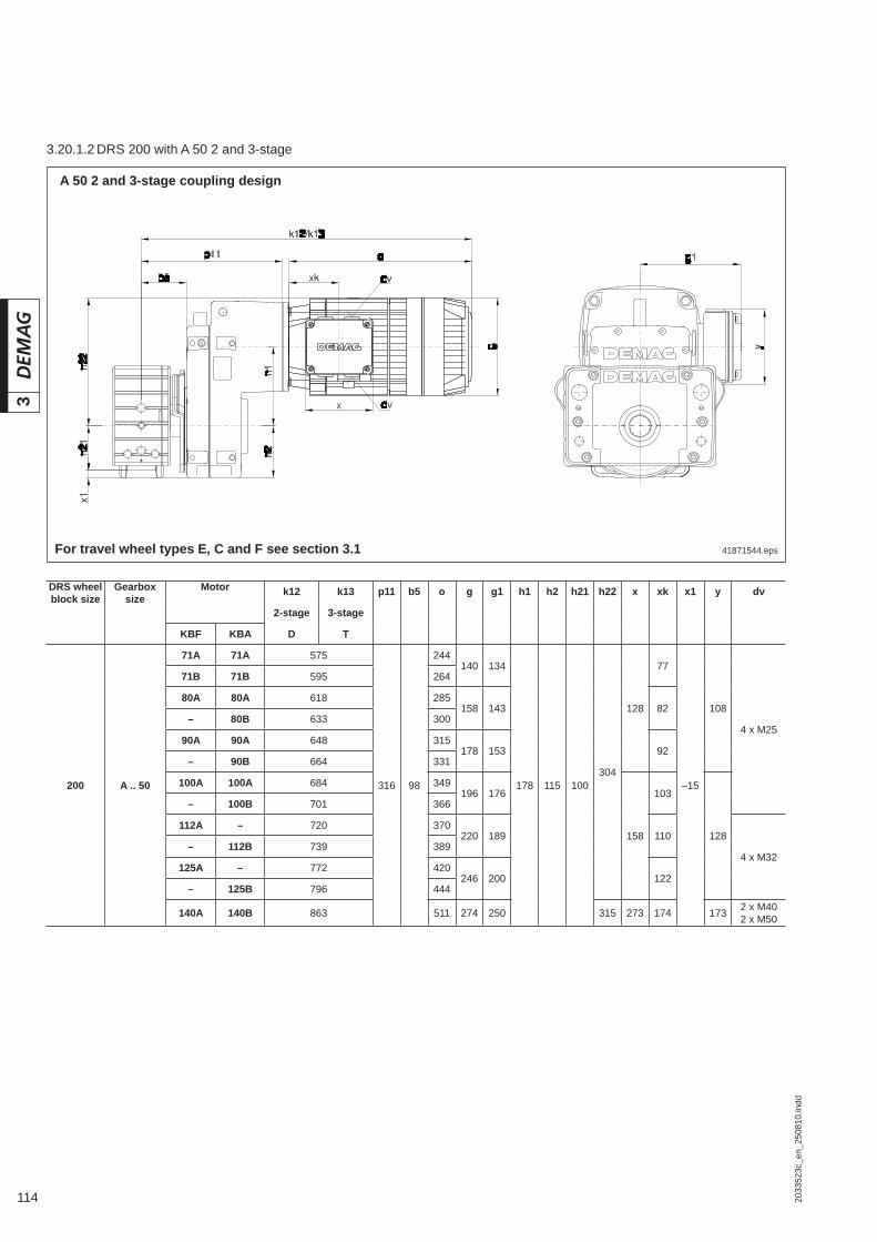
114 2033
523c
_en_
2508
10.in
dd
3
41871544.eps
A 50 2 and 3-stage coupling design
For travel wheel types E, C and F see section 3.1
DRS wheel block size
Gearbox size
Motor k12 k13 p11 b5 o g g1 h1 h2 h21 h22 x xk x1 y dv
2-stage 3-stage
KBF KBA D T
200 A .. 50
71A 71A 575
316 98
244140 134
178 115 100304
128
77
–15
108
4 x M25
71B 71B 595 264
80A 80A 618 285158 143 82
– 80B 633 300
90A 90A 648 315178 153 92
– 90B 664 331
100A 100A 684 349196 176
158
103
128
– 100B 701 366
112A – 720 370220 189 110
4 x M32– 112B 739 389
125A – 772 420246 200 122
– 125B 796 444
140A 140B 863 511 274 250 315 273 174 173 2 x M402 x M50
3.20.1.2 DRS 200 with A 50 2 and 3-stage

1152033
523c
_en_
2508
10.in
dd
3
42013644.eps
A 40 – A 50 2 and 3-stage coupling design
For travel wheel types E, C and F see section 3.2
3.20.2 DRS 250 – 500 wheel block with offset gearbox and KBF/KBA motor
DRS wheel block size
Gearbox size
Motor k12 k13 p11 b5 o g g1 h1 h2 h21 h22 x xk x1 y dv2-stage 3-stage
KBF KBA D T
250
A .. 40
71A 71A 544
282 108
244140 134
148 90 125
228
128
77
+35
108 4 x M25
71B 71B 564 264
80A 80A 587 285158 143 82
– 80B 602 300
90A 90A 617 315178 153 237 92
– 90B 633 331
100A 100A 654 349196 176 246 158 103 128 4 x M32
– 100B 671 366
A .. 50
71A 71A 585
326 108
244140 134
178 115 125304
128
77
+10
108 4 x M25
71B 71B 605 264
80A 80A 628 285158 143 82
– 80B 643 300
90A 90A 658 315178 153 92
– 90B 674 331
100A 100A 694 349196 176
158
103
128 4 x M32
– 100B 711 366
112A – 730 370220 189 110
– 112B 749 389
125A – 782 420246 200 122
– 125B 806 444
140A 140B 873 511 274 250 315 273 174 173 2 x M402 x M50
3.20.2.1 DRS 250 with A 40 – A 50 2 and 3-stage
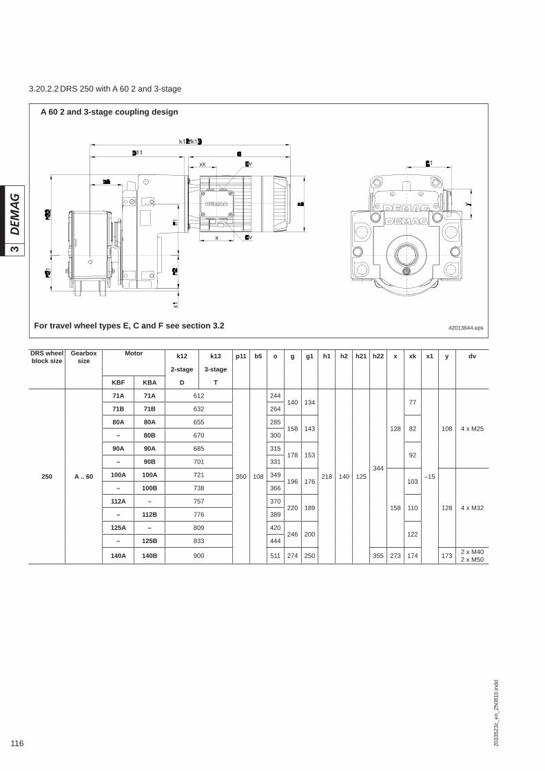
116 2033
523c
_en_
2508
10.in
dd
3
42013644.eps
A 60 2 and 3-stage coupling design
For travel wheel types E, C and F see section 3.2
DRS wheel block size
Gearbox size
Motor k12 k13 p11 b5 o g g1 h1 h2 h21 h22 x xk x1 y dv
2-stage 3-stage
KBF KBA D T
250 A .. 60
71A 71A 612
350 108
244140 134
218 140 125344
128
77
–15
108 4 x M25
71B 71B 632 264
80A 80A 655 285158 143 82
– 80B 670 300
90A 90A 685 315178 153 92
– 90B 701 331
100A 100A 721 349196 176
158
103
128 4 x M32
– 100B 738 366
112A – 757 370220 189 110
– 112B 776 389
125A – 809 420246 200 122
– 125B 833 444
140A 140B 900 511 274 250 355 273 174 173 2 x M402 x M50
3.20.2.2 DRS 250 with A 60 2 and 3-stage

1172033
523c
_en_
2508
10.in
dd
3
42013644.eps
A 50 – A 60 2 and 3-stage coupling design
For travel wheel types E, C and F see section 3.2
DRS wheel block size
Gearbox size
Motor k12 k13 p11 b5 o g g1 h1 h2 h21 h22 x xk x1 y dv
2-stage 3-stage
KBF KBA D T
315
AD. 50
71A 71A 607
348 130
244140 134
178 115 157,5304
128
77
+42(+29)
108 4 x M25
71B 71B 627 264
80A 80A 650 285158 143 82
80B 80B 665 300
90A 90A 680 315178 153 92
90B 90B 696 331
100A 100A 716 349196 176 103
100B 100B 733 366
112A – 752 370220 189
158
110
128 4 x M32– 112B 771 389
125A – 804 420246 200 122
– 125B 828 444
140A 140B 896 511 274 250 315 273 174 173 2 x M402 x M50
AD. 60
71A 71A 634
372 130
244140 134
218 140 157,5344
128
77
+17(+29)
108 4 x M25
71B 71B 654 264
80A 80A 677 285158 143 82
80B 80B 692 300
90A 90A 707 315178 153 92
90B 90B 723 331
100A 100A 743 349196 176
158
103
128 4 x M32
100B 100B 760 366
112A – 779 370220 189 110
– 112B 798 389
125A – 831 420246 200 122
– 125B 855 444
140A 140B 922 511 274 250 355 273 174 173 2 x M402 x M50
(...) Torque bracket obstacle edge
3.20.2.3 DRS 315 with A 50 – A 60, 2 and 3-stage

118 2033
523c
_en_
2508
10.in
dd
3
41680844.eps
AD 60 2 and 3-stage coupling design
For travel wheel types E, C and F see section 3.2
DRS wheel block size
Gearbox size
Motor k12 k13 p11 b5 o g g1 h1 h2 h21 h22 x xk x1 y dv2-stage 3-stage
KBF KBA D T
315 AD. 70
71A 71A 742
484 130
244140 134
272 165 157,5
380
128
77
–8(+29)
108 4 x M25
71B 71B 762 264
80A 80A 785 285158 143 82
80B 80B 800 300
90A 90A 815 315178 153 92
90B 90B 831 331
100A 100A 851 349196 176
158
103
128 4 x M32
100B 100B 868 366
112A – 890 370220 189 382 110
– 112B 909 389
125A – 942
–
420246 200 395 122
– 125B 966 444
140A 140B 1033 511 274 250 409273 174 173 2 x M40
2 x M50– 160B 1144 586 314 269 429
60
AD 70 – AD 80 2 and 3-stage coupling design
(...) Torque bracket obstacle edge
3.20.2.4 DRS 315 – 400 with A 60 - A 80, 2 and 3-stages

1192033
523c
_en_
2508
10.in
dd
3
DRS wheel block size
Gearbox size
Motor k12 k13 p11 b5 o g g1 h1 h2 h21 h22 x xk x1 y dv2-stage 3-stage
KBF KBA D T
400
AD. 60
71A 71A 658
396 154
244140 134
218 140 200344
128
77
+60(+55)
108 4 x M25
71B 71B 678 264
80A 80A 701 285158 143 82
80B 80B 716 300
90A 90A 731 315178 153 92
90B 90B 747 331
100A 100A 767 349196 176
158
103
128 4 x M32
100B 100B 784 366
112A – 803 370220 189 110
– 112B 822 389
125A – 855 420246 200 122
– 125B 879 444
140A 140B 946 511 274 250 355 273 174 173 2 x M402 x M50
AD. 70
71A 71A 766
508 154
244140 134
272 165 200
380
128
77
+35(+55)
108 4 x M25
71B 71B 786 264
80A 80A 809 285158 143 82
80B 80B 824 300
90A 90A 839 315178 153 92
90B 90B 855 331
100A 100A 875 349196 176
158
103
128 4 x M32
100B 100B 892 366
112A – 914 370220 189 382 110
– 112B 933 389
125A – 966
–
420246 200 395 122
– 125B 990 444
140A 140B 1057 511 274 250 409273
174173 2 x M40
2 x M50– 160B 1168 586 314 269 429 221
AD. 80
80A 80A 830
529
154
285158 143
328 201 200
461
128
82
-1(+55)
108 4 x M2580B 80B 845 300
90A 90A 860 315178 153 92
90B 90B 876 331
100A 100A 896 349196 176
158
103
128 4 x M32
100B 100B 913 366
112A – 1006
605
364220 189 110
– 112B 1030 388
125A – 1064 420246 200 122
– 125B 1088 444
140A 140B 1155 512 274 250 465
273
174
173 2 x M402 x M50
– 160B 1267
–
587 314 269 485 221
– 180B 1342 663 354 293 505 237
– 200B 1420 729 394 311 525 246
(...) Torque bracket obstacle edge
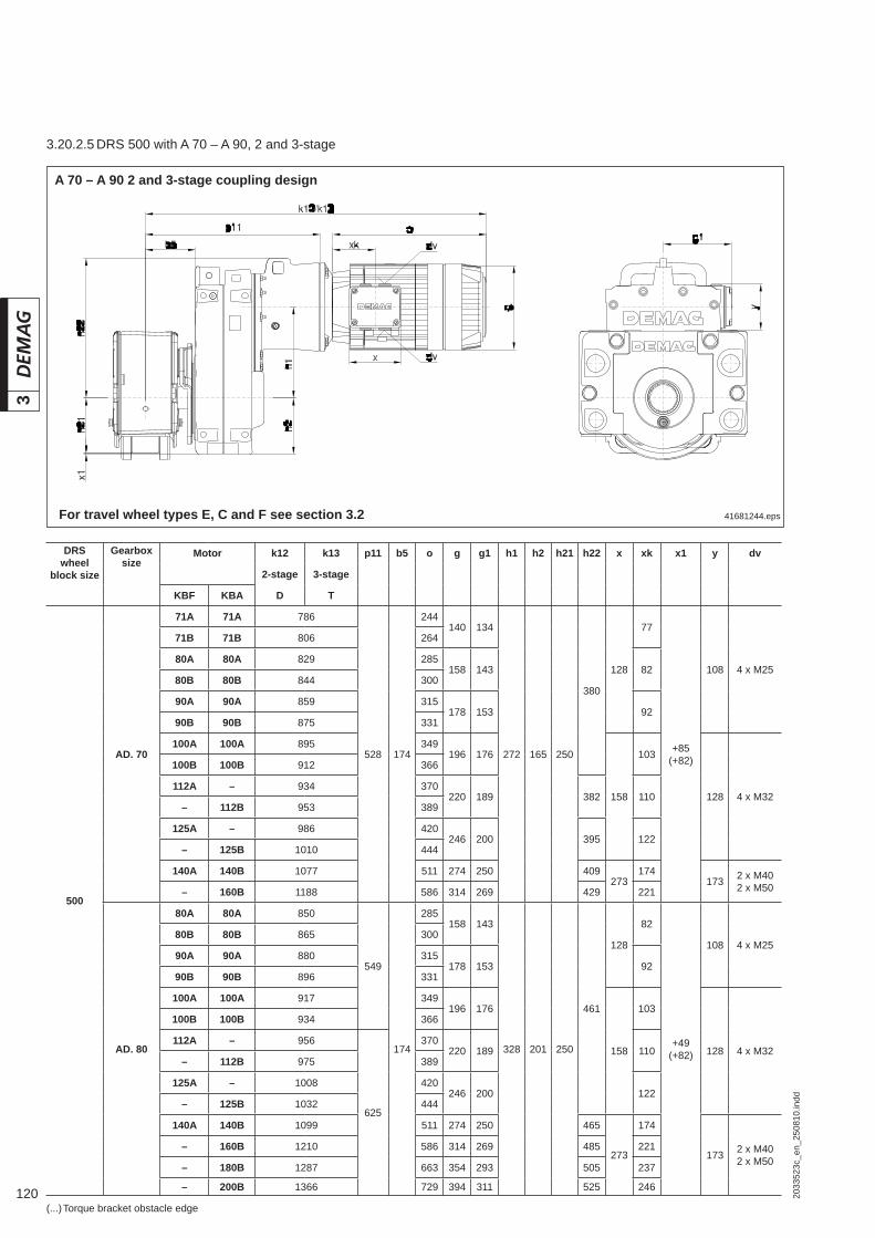
120 2033
523c
_en_
2508
10.in
dd
3
41681244.eps
A 70 – A 90 2 and 3-stage coupling design
For travel wheel types E, C and F see section 3.2
DRS wheel
block size
Gearboxsize
Motor k12 k13 p11 b5 o g g1 h1 h2 h21 h22 x xk x1 y dv
2-stage 3-stage
KBF KBA D T
500
AD. 70
71A 71A 786
528 174
244140 134
272 165 250
380
128
77
+85(+82)
108 4 x M25
71B 71B 806 264
80A 80A 829 285158 143 82
80B 80B 844 300
90A 90A 859 315178 153 92
90B 90B 875 331
100A 100A 895 349196 176
158
103
128 4 x M32
100B 100B 912 366
112A – 934 370220 189 382 110
– 112B 953 389
125A – 986 420246 200 395 122
– 125B 1010 444
140A 140B 1077 511 274 250 409273
174173 2 x M40
2 x M50– 160B 1188 586 314 269 429 221
AD. 80
80A 80A 850
549
174
285158 143
328 201 250
461
128
82
+49(+82)
108 4 x M2580B 80B 865 300
90A 90A 880 315178 153 92
90B 90B 896 331
100A 100A 917 349196 176
158
103
128 4 x M32
100B 100B 934 366
112A – 956
625
370220 189 110
– 112B 975 389
125A – 1008 420246 200 122
– 125B 1032 444
140A 140B 1099 511 274 250 465
273
174
173 2 x M402 x M50
– 160B 1210 586 314 269 485 221
– 180B 1287 663 354 293 505 237
– 200B 1366 729 394 311 525 246
(...) Torque bracket obstacle edge
3.20.2.5 DRS 500 with A 70 – A 90, 2 and 3-stage

1212033
523c
_en_
2508
10.in
dd
3
3.21 Dimensions of travel drive with angular geared motor, coupling connection
DRS wheel block size
Gearbox size
Motor k12 k13 p11 b5 o g g1 h1 h2 h21 h22 x xk x1 y dv
2-stage 3-stage
KBF KBA D T
500 AU. 90
112A – 1055
648 174
370220 189
395 240 250
564
158
110
+10(+82)
128 4 x M32– 112B 1074 389
125A – 1107 420246 200 122
– 125B 1131 444
140A 140B 1198 511 274 250
273
174
173 2 x M402 x M50
– 160B 1309 586 314 269 221
– 180B 1386 663 354 293 572 237
– 200B 1465 729 394 311 592 246
– 225B 1505 769 440 332 615 256
41815844.eps
3.21.1 DRS 112 – 200 wheel block with angular gearbox and KBF/KBA motor
W 10 – W 20 2-stage coupling design
For travel wheel types E, C and F see section 3.1
DRS wheel block size
Gearbox size
Motor k12 q12 b5 b6 b7 o g g1 h1 h21 h22 x xk x1 y dv
KBF KBA
112
WU . 10
71A 71A 542
285 81 198
207244
140 134
21,3 56 103,3 128
77–9
(–18) 108 4 x M2571B 71B 562 264
80A 80A 585216
285158 143 82
– 80B 600 300
WU . 20
71A 71A 555
299,5 81 218
216244
140 134
24,5 56 111,5 128
77
(–18) 108 4 x M25
71B 71B 575 264
80A 80A 598226
285158 143 82
– 80B 613 300
90A 90A 628235
315178 153 92
– 90B 644 331
125 WU . 10
71A 71A 542
285 87 204
224244
140 134
21,3 62,5 103,3 128
77–2
(–13) 108 4 x M2571B 71B 562 264
80A 80A 585244
285158 143 82
– 80B 600 300
(...) Torque bracket obstacle edge
3.21.1.1 DRS 112 – 125 with W 20 – W 20, 2-stage
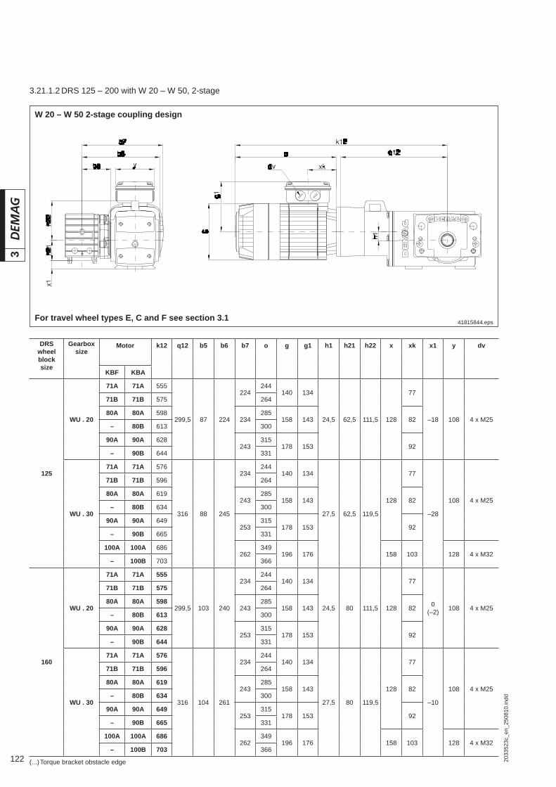
122 2033
523c
_en_
2508
10.in
dd
3
41815844.eps
W 20 – W 50 2-stage coupling design
For travel wheel types E, C and F see section 3.1
DRS wheel block size
Gearboxsize
Motor k12 q12 b5 b6 b7 o g g1 h1 h21 h22 x xk x1 y dv
KBF KBA
125
WU . 20
71A 71A 555
299,5 87 224
224244
140 134
24,5 62,5 111,5 128
77
–18 108 4 x M25
71B 71B 575 264
80A 80A 598234
285158 143 82
– 80B 613 300
90A 90A 628243
315178 153 92
– 90B 644 331
WU . 30
71A 71A 576
316 88 245
234244
140 134
27,5 62,5 119,5
128
77
–28
108 4 x M25
71B 71B 596 264
80A 80A 619243
285158 143 82
– 80B 634 300
90A 90A 649253
315178 153 92
– 90B 665 331
100A 100A 686262
349196 176 158 103 128 4 x M32
– 100B 703 366
160
WU . 20
71A 71A 555
299,5 103 240
234244
140 134
24,5 80 111,5 128
77
0(–2) 108 4 x M25
71B 71B 575 264
80A 80A 598243
285158 143 82
– 80B 613 300
90A 90A 628253
315178 153 92
– 90B 644 331
WU . 30
71A 71A 576
316 104 261
234244
140 134
27,5 80 119,5
128
77
–10
108 4 x M25
71B 71B 596 264
80A 80A 619243
285158 143 82
– 80B 634 300
90A 90A 649253
315178 153 92
– 90B 665 331
100A 100A 686262
349196 176 158 103 128 4 x M32
– 100B 703 366
(...) Torque bracket obstacle edge
3.21.1.2 DRS 125 – 200 with W 20 – W 50, 2-stage
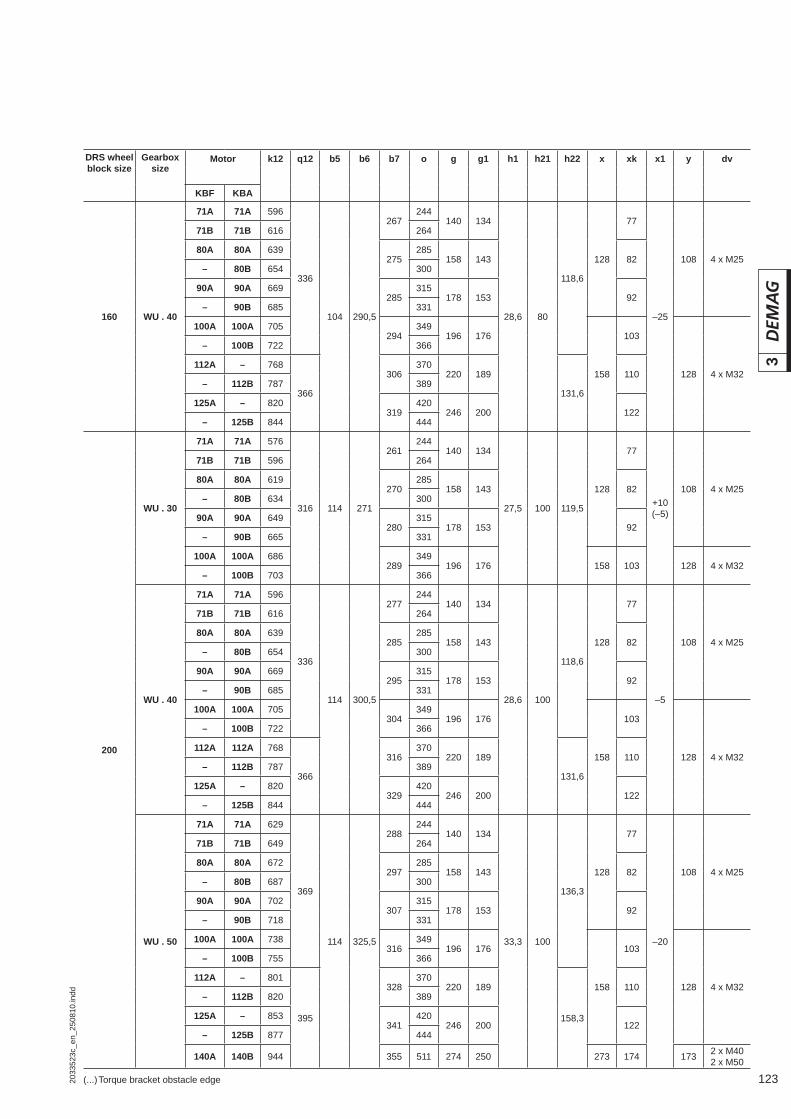
1232033
523c
_en_
2508
10.in
dd
3
(...) Torque bracket obstacle edge
DRS wheel block size
Gearbox size
Motor k12 q12 b5 b6 b7 o g g1 h1 h21 h22 x xk x1 y dv
KBF KBA
160 WU . 40
71A 71A 596
336
104 290,5
267244
140 134
28,6 80
118,6
128
77
–25
108 4 x M25
71B 71B 616 264
80A 80A 639275
285158 143 82
– 80B 654 300
90A 90A 669285
315178 153 92
– 90B 685 331
100A 100A 705294
349196 176
158
103
128 4 x M32
– 100B 722 366
112A – 768
366
306370
220 189
131,6
110– 112B 787 389
125A – 820319
420246 200 122
– 125B 844 444
200
WU . 30
71A 71A 576
316 114 271
261244
140 134
27,5 100 119,5
128
77
+10(–5)
108 4 x M25
71B 71B 596 264
80A 80A 619270
285158 143 82
– 80B 634 300
90A 90A 649280
315178 153 92
– 90B 665 331
100A 100A 686289
349196 176 158 103 128 4 x M32
– 100B 703 366
WU . 40
71A 71A 596
336
114 300,5
277244
140 134
28,6 100
118,6
128
77
–5
108 4 x M25
71B 71B 616 264
80A 80A 639285
285158 143 82
– 80B 654 300
90A 90A 669295
315178 153 92
– 90B 685 331
100A 100A 705304
349196 176
158
103
128 4 x M32
– 100B 722 366
112A 112A 768
366
316370
220 189
131,6
110– 112B 787 389
125A – 820329
420246 200 122
– 125B 844 444
WU . 50
71A 71A 629
369
114 325,5
288244
140 134
33,3 100
136,3
128
77
–20
108 4 x M25
71B 71B 649 264
80A 80A 672297
285158 143 82
– 80B 687 300
90A 90A 702307
315178 153 92
– 90B 718 331
100A 100A 738316
349196 176
158
103
128 4 x M32
– 100B 755 366
112A – 801
395
328370
220 189
158,3
110– 112B 820 389
125A – 853341
420246 200 122
– 125B 877 444
140A 140B 944 355 511 274 250 273 174 173 2 x M402 x M50
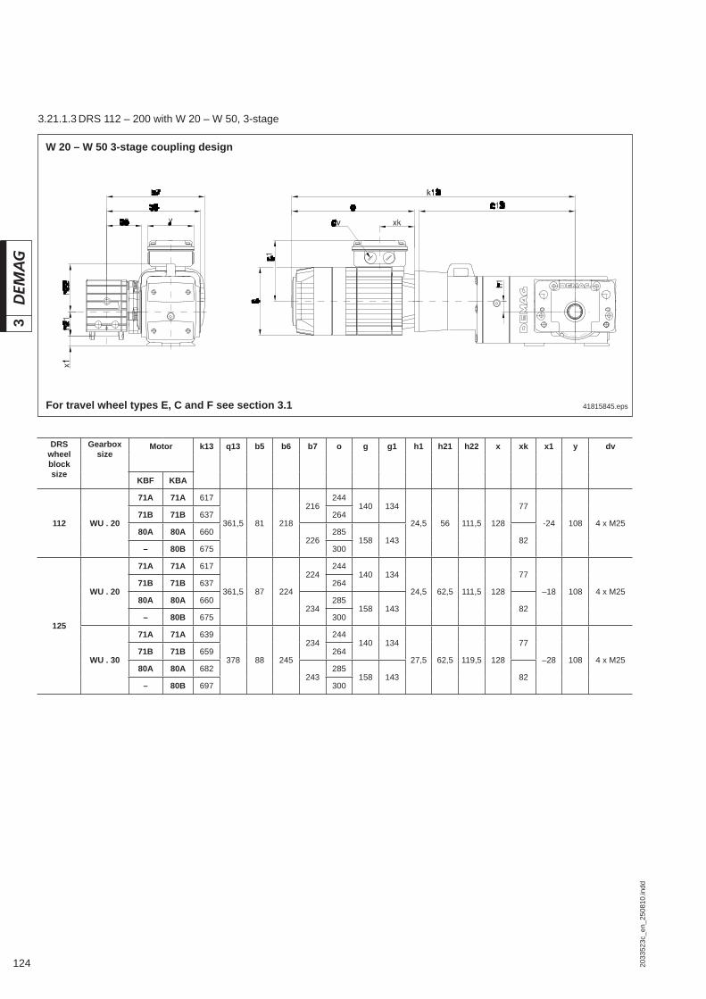
124 2033
523c
_en_
2508
10.in
dd
3
DRS wheel block size
Gearbox size
Motor k13 q13 b5 b6 b7 o g g1 h1 h21 h22 x xk x1 y dv
KBF KBA
112 WU . 20
71A 71A 617
361,5 81 218
216244
140 134
24,5 56 111,5 128
77
-24 108 4 x M2571B 71B 637 264
80A 80A 660226
285158 143 82
– 80B 675 300
125
WU . 20
71A 71A 617
361,5 87 224
224244
140 134
24,5 62,5 111,5 128
77
–18 108 4 x M2571B 71B 637 264
80A 80A 660234
285158 143 82
– 80B 675 300
WU . 30
71A 71A 639
378 88 245
234244
140 134
27,5 62,5 119,5 128
77
–28 108 4 x M2571B 71B 659 264
80A 80A 682243
285158 143 82
– 80B 697 300
41815845.eps
W 20 – W 50 3-stage coupling design
For travel wheel types E, C and F see section 3.1
3.21.1.3 DRS 112 – 200 with W 20 – W 50, 3-stage

1252033
523c
_en_
2508
10.in
dd
3
DRS wheel block size
Gearboxsize
Motor k13 q13 b5 b6 b7 o g g1 h1 h21 h22 x xk x1 y dv
KBF KBA
160
WU . 20
71A 71A 617
361,5 103 240
241244
140 134
24,5 80 111,5 128
770
(–2) 108 4 x M2571B 71B 637 264
80A 80A 660250
285158 143 82
– 80B 675 300
WU . 30
71A 71A 639
378 104 261
251244
140 134
27,5 80 119,5 128
77
–10 108 4 x M2571B 71B 659 264
80A 80A 682260
285158 143 82
– 80B 697 300
WU . 40
71A 71A 666
406 104 290,5
267244
140 134
28,6 80 118,6 128
77
–25 108 4 x M2571B 71B 686 264
80A 80A 709275
285158 143 82
– 80B 724 300
200
WU . 30
71A 71A 639
378 114 271
261244
140 134
27,5 100 119,5 128
7710
(–5) 108 4 x M2571B 71B 659 264
80A 80A 682270
285158 143 82
– 80B 697 300
WU . 40
71A 71A 666
406
114
300,5
277244
140 134
28,6 100 118,6 128
77
–5 108 4 x M2571B 71B 686 264
80A 80A 709285
285158 143 82
– 80B 724 300
WU . 50
71A 71A 699
439 325,5
288244
140 134
33,3 100 136,3 128
77
–20 108 4 x M2571B 71B 719 264
80A 80A 742297
285158 143 82
– 80B 757 300
(...) Torque bracket obstacle edge
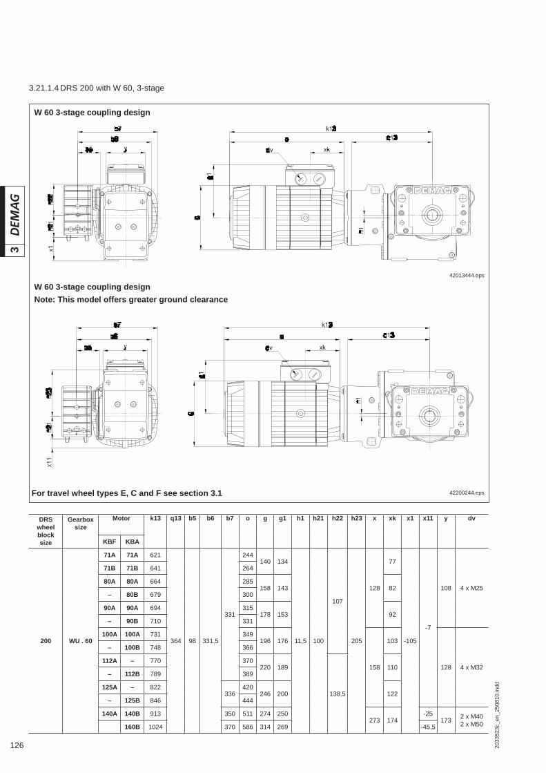
126 2033
523c
_en_
2508
10.in
dd
3
42200244.eps
W 60 3-stage coupling designNote: This model offers greater ground clearance
42013444.eps
W 60 3-stage coupling design
For travel wheel types E, C and F see section 3.1
DRS wheel block size
Gearbox size
Motor k13 q13 b5 b6 b7 o g g1 h1 h21 h22 h23 x xk x1 x11 y dv
KBF KBA
200 WU . 60
71A 71A 621
364 98 331,5
331
244140 134
11,5 100
107
205
128
77
-105
-7
108 4 x M25
71B 71B 641 264
80A 80A 664 285158 143 82
– 80B 679 300
90A 90A 694 315178 153 92
– 90B 710 331
100A 100A 731 349196 176
158
103
128 4 x M32
– 100B 748 366
112A – 770 370220 189
138,5
110– 112B 789 389
125A – 822336
420246 200 122
– 125B 846 444
140A 140B 913 350 511 274 250273 174
-25173 2 x M40
2 x M50160B 1024 370 586 314 269 -45,5
3.21.1.4 DRS 200 with W 60, 3-stage
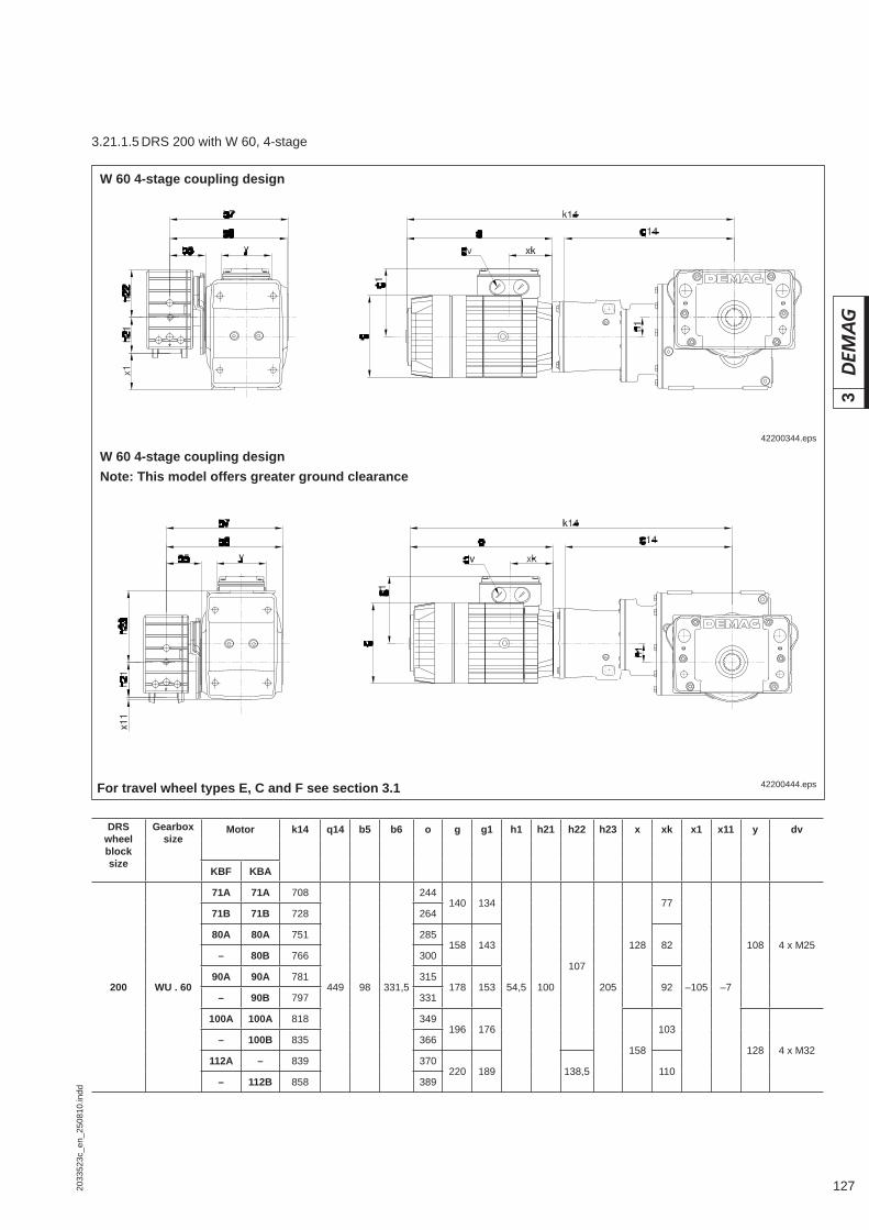
1272033
523c
_en_
2508
10.in
dd
3
42200444.eps
W 60 4-stage coupling design Note: This model offers greater ground clearance
For travel wheel types E, C and F see section 3.1
42200344.eps
W 60 4-stage coupling design
DRS wheel block size
Gearbox size
Motor k14 q14 b5 b6 o g g1 h1 h21 h22 h23 x xk x1 x11 y dv
KBF KBA
200 WU . 60
71A 71A 708
449 98 331,5
244140 134
54,5 100
107
205
128
77
–105 –7
108 4 x M25
71B 71B 728 264
80A 80A 751 285158 143 82
– 80B 766 300
90A 90A 781 315178 153 92
– 90B 797 331
100A 100A 818 349196 176
158
103
128 4 x M32– 100B 835 366
112A – 839 370220 189 138,5 110
– 112B 858 389
3.21.1.5 DRS 200 with W 60, 4-stage
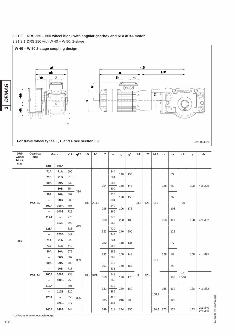
128 2033
523c
_en_
2508
10.in
dd
3
42014144.eps
3.21.2 DRS 250 – 500 wheel block with angular gearbox and KBF/KBA motor
W 40 – W 50 2-stage coupling design
For travel wheel types E, C and F see section 3.2
DRS wheel block size
Gearboxsize
Motor k12 q12 b5 b6 b7 o g g1 h1 h21 h22 x xk x1 y dv
KBF KBA
250
WU . 40
71A 71A 596
336
108 294,5
294
244140 134
28,6 125 156
128
77
+20
108 4 x M25
71B 71B 616 264
80A 80A 639 285158 143 82
– 80B 654 300
90A 90A 669 315178 153 92
– 90B 685 331
100A 100A 705298
349196 176
158
103
128 4 x M32
– 100B 722 366
112A – 773
366
310370
220 189 110– 112B 792 389
125A – 823323
420246 200 122
– 125B 847 444
WU . 50
71A 71A 629
369
108 319,5
282244
140 134
33,3 125
156
128
77
+5(+20)
108 4 x M25
71B 71B 649 264
80A 80A 672292
285158 143 82
– 80B 687 300
90A 90A 702301
315178 153 92
– 90B 718 331
100A 100A 738310
349196 176
158
103
128 4 x M32
– 100B 755 366
112A – 801
395
322370
220 189
158,3
110– 112B 820 389
125A – 853335
420246 200 122
– 125B 877 444
140A 140B 944 349 511 274 250 170,3 273 174 173 2 x M402 x M50
(...) Torque bracket obstacle edge
3.21.2.1 DRS 250 with W 40 – W 50, 2-stage

1292033
523c
_en_
2508
10.in
dd
3
DRS wheel block size
Gearbox size
Motor k13 q13 b5 b6 b7 o g g1 h1 h21 h22 x xk x1 y dv
KBF KBA
250
WU . 40
71A 71A 666
406 108 294,5 294
244140 134
28,6 125 156 128
77
+20 108 4 x M2571B 71B 686 264
80A 80A 709 285158 143 82
– 80B 724 300
WU . 50
71A 71A 699
439 108 319,5
282244
140 134
33,3 125 156 158
77+5
(+20) 128 4 x M2571B 71B 719 264
80A 80A 742292
285158 143 82
– 80B 757 300
42014145.eps
W 40 – W 50 3-stage coupling design
For travel wheel types E, C and F see section 3.2
(...) Torque bracket obstacle edge
3.21.2.2 DRS 250 with W 40 – W 50, 3-stage

130 2033
523c
_en_
2508
10.in
dd
3
DRS wheel block size
Gearbox size
Motor k12 q12 b5 b6 b7 o g g1 h1 h21 h22 x xk x1 y dv
KBF KBA
315 WU . 50
71A 71A 629
369
130 341,5
304
244140 134
33,3 157,5 193
128
77
+37(+29)
108 4 x M25
71B 71B 649 264
80A 80A 672 285158 143 82
– 80B 687 313 300
90A 90A 702323
315178 153 92
– 90B 718 331
100A 100A 738332
349196 176
158
103
128 4 x M32
– 100B 755 366
112A – 801
395
344370
220 189 110– 112B 820 389
125A – 853357
420246 200 122
– 125B 877 444
140A 140B 944 371 511 274 250 273 174 173 2 x M402 x M50
42014144.eps
W 50 2-stage coupling design
For travel wheel types E, C and F see section 3.2
(...) Torque bracket obstacle edge
3.21.2.3 DRS 315 with W 50, 2-stage

1312033
523c
_en_
2508
10.in
dd
3
DRS wheel block size
Gearbox size
Motor k13 q13 b5 b6 b7 o g g1 h1 h21 h22 x xk x1 y dv
KBF KBA
315 WU . 50
71A 71A 699
439 130 341,5304
244140 134
33,3 157,5 193 128
77+37
(+29) 108 4 x M2571B 71B 719 264
80A 80A 742 285158 143 82
– 80B 757 313 300
42014145.eps
W 50 3-stage coupling design
For travel wheel types E, C and F see section 3.2
(...) Torque bracket obstacle edge
3.21.2.4 DRS 315 with W 50, 3-stage
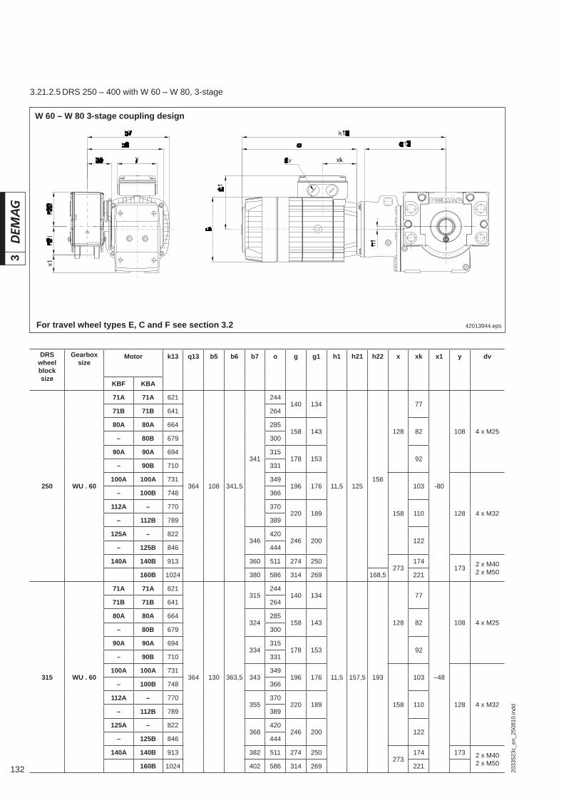
132 2033
523c
_en_
2508
10.in
dd
3
42013944.eps
W 60 – W 80 3-stage coupling design
For travel wheel types E, C and F see section 3.2
DRS wheel block size
Gearbox size
Motor k13 q13 b5 b6 b7 o g g1 h1 h21 h22 x xk x1 y dv
KBF KBA
250 WU . 60
71A 71A 621
364 108 341,5
341
244140 134
11,5 125156
128
77
-80
108 4 x M25
71B 71B 641 264
80A 80A 664 285158 143 82
– 80B 679 300
90A 90A 694 315178 153 92
– 90B 710 331
100A 100A 731 349196 176
158
103
128 4 x M32
– 100B 748 366
112A – 770 370220 189 110
– 112B 789 389
125A – 822346
420246 200 122
– 125B 846 444
140A 140B 913 360 511 274 250273
174173 2 x M40
2 x M50160B 1024 380 586 314 269 168,5 221
315 WU . 60
71A 71A 621
364 130 363,5
315244
140 134
11,5 157,5 193
128
77
–48
108 4 x M25
71B 71B 641 264
80A 80A 664324
285158 143 82
– 80B 679 300
90A 90A 694334
315178 153 92
– 90B 710 331
100A 100A 731343
349196 176
158
103
128 4 x M32
– 100B 748 366
112A – 770355
370220 189 110
– 112B 789 389
125A – 822368
420246 200 122
– 125B 846 444
140A 140B 913 382 511 274 250273
174 173 2 x M402 x M50160B 1024 402 586 314 269 221
3.21.2.5 DRS 250 – 400 with W 60 – W 80, 3-stage

1332033
523c
_en_
2508
10.in
dd
3
DRS wheel block size
Gearbox size
Motor k13 q13 b5 b6 b7 o g g1 h1 h21 h22 x xk x1 y dv
KBF KBA
315
WU . 70
71A 71A 649
387
130 404
335244
140 134
6 157,5 193
128
77
–88
108 4 x M25
71B 71B 669 264
80A 80A 692344
285158 143 82
– 80B 707 300
90A 90A 722354
315178 153 92
– 90B 738 331
100A 100A 759363
349196 176
158
103
128 4 x M32
– 100B 776 366
112A – 873
462
375370
220 189 110– 112B 892 389
125A – 925388
420246 200 122
– 125B 949 444
140A 140B 1016 402 511 274 250
273
174
173 2 x M402 x M50
– 160B 1127 422 586 314 269 221
– 180B 1204 442 663 354 293 237
– 200B 1283 462 729 394 311 246
WU. 80
71A 71A 664
406
130 409
338244
140 134
32 157,5 193
128
77
–118
108 4 x M25
71B 71B 684 264
80A 80A 707347
285158 143 82
– 80B 722 300
90A 90A 737357
315178 153 92
– 90B 753 331
100A 100A 773366
349196 176
158
103
128 4 x M32
– 100B 790 366
112A – 888
481
378370
220 189 110– 112B 907 389
125A – 940391
420246 200 122
– 125B 964 444
140A 140B 1031 405 511 274 250
273
174
173 2 x M402 x M50
– 160B 1142 425 586 314 269 221
– 180B 1219 445 663 354 293 237
– 200B 1298 465 729 394 311 246
400 WU . 70
71A 71A 649
387
154 428
359244
140 134
6 200 240
128
77
–45
108 4 x M25
71B 71B 669 264
80A 80A 692368
285158 143 82
– 80B 707 300
90A 90A 722378
315178 153 92
– 90B 738 331
100A 100A 759387
349196 176
158
103
128 4 x M32
– 100B 776 366
112A – 873
462
399370
220 189 110– 112B 892 389
125A – 925412
420246 200 122
– 125B 949 444
140A 140B 1016 426 511 274 250
273
174
173 2 x M402 x M50
– 160B 1127 446 586 314 269 221
– 180B 1204 466 663 354 293 237
– 200B 1283 486 729 394 311 246
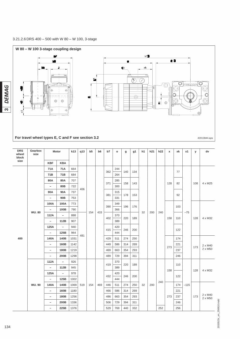
134 2033
523c
_en_
2508
10.in
dd
3
DRS wheel block size
Gearbox size
Motor k13 q13 b5 b6 b7 o g g1 h1 h21 h22 x xk x1 y dv
KBF KBA
400
WU. 80
71A 71A 664
406
154 433
362244
140 134
32 200 240
128
77
–75
108 4 x M25
71B 71B 684 264
80A 80A 707371
285158 143 82
– 80B 722 300
90A 90A 737381
315178 153 92
– 90B 753 331
100A 100A 773390
349196 176
158
103
128 4 x M32
– 100B 790 366
112A – 888
481
402370
220 189 110– 112B 907 389
125A – 940415
420246 200 122
– 125B 964 444
140A 140B 1031 429 511 274 250
273
174
173 2 x M402 x M50
– 160B 1142 449 586 314 269 221
– 180B 1219 469 663 354 293 237
– 200B 1298 489 729 394 311 246
WU. 90
112A – 926
519 154 469
419370
220 189
32 200240
158
110
–115
128 4 x M32– 112B 945 389
125A – 978432
420246 200 122
– 125B 1002 444
140A 140B 1069 446 511 274 250
273
174
173 2 x M402 x M50
– 160B 1180 466 586 314 269 221
– 180B 1256 486 663 354 293 237
– 200B 1336 506 729 394 311 246
– 225B 1376 529 769 440 332 252 256
42013944.eps
W 80 – W 100 3-stage coupling design
For travel wheel types E, C and F see section 3.2
3.21.2.6 DRS 400 – 500 with W 80 – W 100, 3-stage
1352033
523c
_en_
2508
10.in
dd
3
DRS wheel block size
Gearbox size
Motor k13 q13 b5 b6 b7 o g g1 h1 h21 h22 x xk x1 y dv
KBF KBA
500
WU. 80
71A 71A 664
406
174 453
382244
140 134
32 250 316
128
77
–25
108 4 x M25
71B 71B 684 264
80A 80A 707391
285158 143 82
– 80B 722 300
90A 90A 737401
315178 153 92
– 90B 753 331
100A 100A 773410
349196 176 158
– 100B 790 366
112A – 888
481
422370
220 189
103
110
128 4 x M32– 112B 907 389
125A – 940435
420246 200 122
– 125B 964 444
140A 140B 1031 449 511 274 250
273
174
173 2 x M402 x M50
– 160B 1142 469 586 314 269 221
– 180B 1219 489 663 354 293 237
– 200B 1298 509 729 394 311 246
WU. 90
112A – 926
519 174 489
439370
220 189
32 250 316
103
110
–65
128 4 x M32– 112B 945 389
125A – 978452
420246 200 122
– 125B 1002 444
140A 140B 1069 466 511 274 250
273
174
173 2 x M402 x M50
– 160B 1180 486 586 314 269 221
– 180B 1256 506 663 354 293 237
– 200B 1336 526 729 394 311 246
– 225B 1376 549 769 440 332 256
WU. 100
112A – 986
580 174 559
474370
220 189
44 250 316
103
110
–140
128 4 x M32– 112B 1005 389
125A – 1038487
420246 200 122
– 125B 1062 444
140A 140B 1138 501 511 274 250
273
174
173 2 x M402 x M50
– 160B 1240 521 586 314 269 221
– 180B 1317 543 663 354 293 237
– 200B 1396 561 729 394 311 246
– 225B 1436 584 769 440 332

136 2033
523c
_en_
2508
10.in
dd
3
42200544.eps
W 60 – W 80 3-stage coupling designNote: This model offers greater ground clearance
For travel wheel types E, C and F see section 3.2
DRS wheel block size
Gearbox size
Motor k13 q13 b5 b6 b7 o g g1 h1 h21 h23 x xk x11 y dv
KBF KBA
250 WU . 60
71A 71A 621
364 108 341,5
341
244140 134
11,5 125 205
128
77
+18 108 4 x M25
71B 71B 641 264
80A 80A 664 285158 143 82
– 80B 679 300
90A 90A 694 315178 153 92
– 90B 710 331
100A 100A 731 349196 176 103
– 100B 748 366
112A – 770 370220 189
158
110
+13,5 128 4 x M32– 112B 789 389
125A – 822346
420246 200 122
– 125B 846 444
140A 140B 913 360 511 274 250273
174 -0,5173 2 x M40
2 x M50160B 1024 380 586 314 269 221 -21
315 WU . 60
71A 71A 621
364 130 363,5
315244
140 134
11,5 157,5 205
128
77
+30
108 4 x M25
71B 71B 641 264
80A 80A 664324
285158 143 82
– 80B 679 300
90A 90A 694334
315178 153 92
– 90B 710 331
100A 100A 731343
349196 176 103
– 100B 748 366
112A – 770355
370220 189
158
110
128 4 x M32– 112B 789 389
125A – 822368
420246 200 122
– 125B 846 444
140A 140B 913 382 511 274 250273
174173 2 x M40
2 x M50160B 1024 402 586 314 269 221 +12
3.21.2.7 DRS 250 – 315 with W 60 – W 80, 3-stage
1372033
523c
_en_
2508
10.in
dd
3
DRS wheel block size
Gearbox size
Motor k13 q13 b5 b6 b7 o g g1 h1 h21 h23 x xk x11 y dv
KBF KBA
315
WU . 70
71A 71A 649
387
130 404
335244
140 134
6 157,5 245
128
77
+29,5
108 4 x M25
71B 71B 669 264
80A 80A 692344
285158 143 82
– 80B 707 300
90A 90A 722354
315178 153 92
– 90B 738 331
100A 100A 759363
349196 176 103
– 100B 776 366
112A – 873
462
375370
220 189
158
110
128 4 x M32– 112B 892 389
125A – 925388
420246 200 122
– 125B 949 444
140A 140B 1016 402 511 274 250
273
174 +26,5
173 2 x M402 x M50
– 160B 1127 422 586 314 269 221 +6,5
– 180B 1204 442 663 354 284 237 -14
– 200B 1283 462 729 394 311 246 -34
WU. 80
71A 71A 664
406
130 409
338244
140 134
32 157,5 275
128
77
+15,5
108 4 x M25
71B 71B 684 264
80A 80A 707347
285158 143 82
– 80B 722 300
90A 90A 737357
315178 153 92
– 90B 753 331
100A 100A 773366
349196 176 103
– 100B 790 366
112A – 888
481
378370
220 189
158
110
128 4 x M32– 112B 907 389
125A – 940391
420246 200 122
– 125B 964 444
140A 140B 1031 405 511 274 250
273
174
173 2 x M402 x M50
– 160B 1142 425 586 314 269 221
– 180B 1219 445 663 354 284 237 +12,5
– 200B 1298 465 729 394 311 246 -8
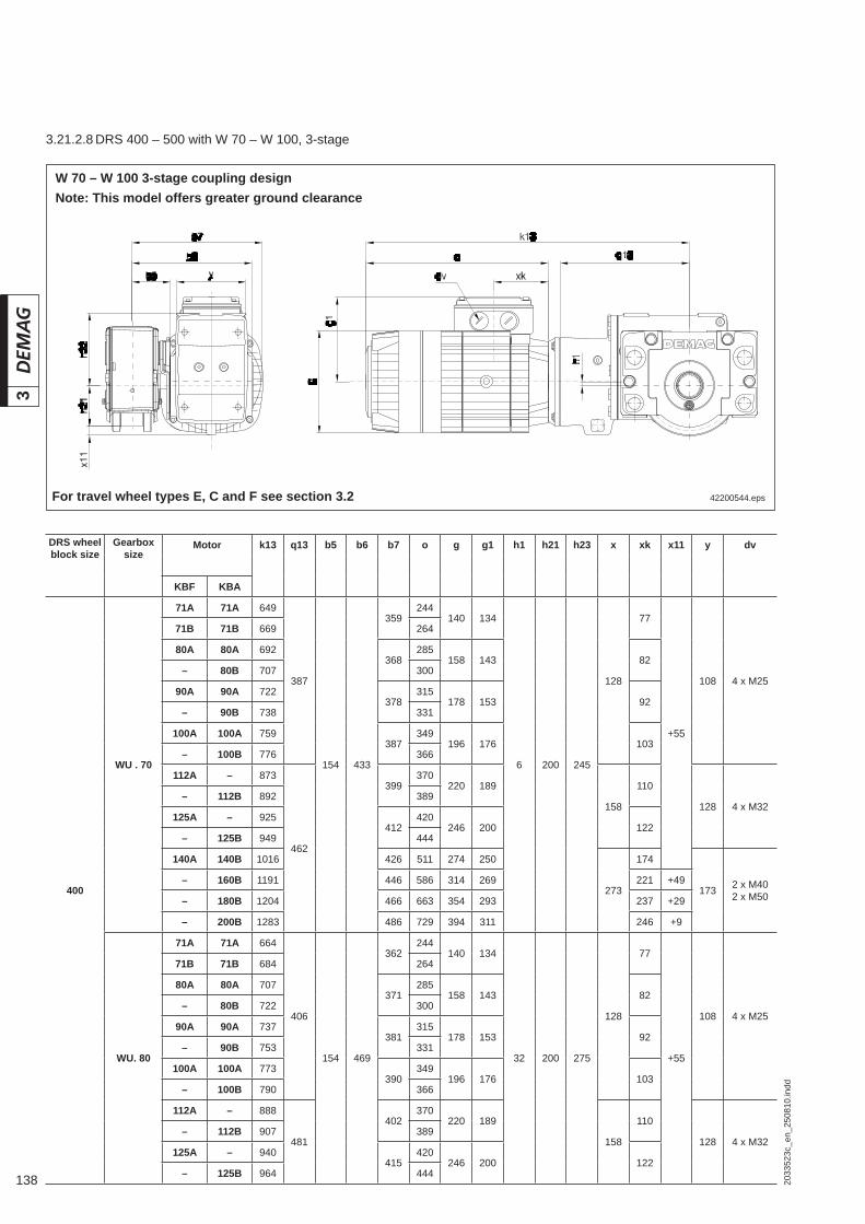
138 2033
523c
_en_
2508
10.in
dd
3
DRS wheel block size
Gearbox size
Motor k13 q13 b5 b6 b7 o g g1 h1 h21 h23 x xk x11 y dv
KBF KBA
400
WU . 70
71A 71A 649
387
154 433
359244
140 134
6 200 245
128
77
+55
108 4 x M25
71B 71B 669 264
80A 80A 692368
285158 143 82
– 80B 707 300
90A 90A 722378
315178 153 92
– 90B 738 331
100A 100A 759387
349196 176 103
– 100B 776 366
112A – 873
462
399370
220 189
158
110
128 4 x M32– 112B 892 389
125A – 925412
420246 200 122
– 125B 949 444
140A 140B 1016 426 511 274 250
273
174
173 2 x M402 x M50
– 160B 1191 446 586 314 269 221 +49
– 180B 1204 466 663 354 293 237 +29
– 200B 1283 486 729 394 311 246 +9
WU. 80
71A 71A 664
406
154 469
362244
140 134
32 200 275
128
77
+55
108 4 x M25
71B 71B 684 264
80A 80A 707371
285158 143 82
– 80B 722 300
90A 90A 737381
315178 153 92
– 90B 753 331
100A 100A 773390
349196 176 103
– 100B 790 366
112A – 888
481
402370
220 189
158
110
128 4 x M32– 112B 907 389
125A – 940415
420246 200 122
– 125B 964 444
42200544.eps
W 70 – W 100 3-stage coupling designNote: This model offers greater ground clearance
For travel wheel types E, C and F see section 3.2
3.21.2.8 DRS 400 – 500 with W 70 – W 100, 3-stage
1392033
523c
_en_
2508
10.in
dd
3
DRS wheel block size
Gearbox size
Motor k13 q13 b5 b6 b7 o g g1 h1 h21 h23 x xk x11 y dv
KBF KBA
400
WU. 80
140A 140B 1031
481 154 433
429 511 274 250
32 200 275 273
174
+55173 2 x M40
2 x M50– 160B 1142 449 586 314 269 221
– 180B 1219 469 663 354 293 237
– 200B 1298 489 729 394 311 246 +35
WU. 90
112A – 928
519 154 469
419370
220 189
32 200 315
158
110
+34
128 4 x M32– 112B 947 389
125A – 978432
420246 200 122
– 125B 1002 444
140A 140B 1069 446 511 274 250
273
174
173 2 x M402 x M50
– 160B 1180 466 586 314 269 221
– 180B 1270 486 663 354 293 237
– 200B 1336 506 729 394 311 246
– 225B 1376 529 769 440 332 256 +12
500
WU. 80
71A 71A 664
406
174 453
382244
140 134
32 250 275
128
77
+82
108 4 x M25
71B 71B 684 264
80A 80A 707391
285158 143 82
– 80B 722 300
90A 90A 737401
315178 153 92
– 90B 753 331
100A 100A 773410
349196 176 103
– 100B 790 366
112A – 888
481
422370
220 189
158
110
128 4 x M32– 112B 907 389
125A – 940435
420246 200 122
– 125B 964 444
140A 140B 1031 449 511 274 250
273
174
173 2 x M402 x M50
– 160B 1142 469 586 314 269 221
– 180B 1219 489 663 354 293 237
– 200B 1298 509 729 394 311 246
WU. 90
112A – 928
519 174 489
439370
220 189
32 250 315
158
110
128 4 x M32– 112B 947 389
125A – 978452
420246 200 122
– 125B 1002 444
140A 140B 1069 466 511 274 250
273
174
173 2 x M402 x M50
– 160B 1180 486 586 314 269 221
– 180B 1270 506 663 354 293 237
– 200B 1336 526 729 394 311 246
– 225B 1376 549 769 440 332 256 +62
WU. 100
112A – 986
580 174 559
474370
220 189
44 250 390
158
110
+44
128 4 x M32– 112B 1005 389
125A – 1038487
420246 200 122
– 125B 1067 444
140A 140B 1138 501 511 274 250
273
174
173 2 x M402 x M50
– 160B 1240 521 586 314 269 221
– 180B 1317 543 663 354 293 237
– 200B 1396 561 729 394 311 246
– 225B 1436 584 769 440 332 256

140 2033
523c
_en_
2508
10.in
dd
3
42200644.eps
W 60 – W 80 4-stage coupling design
For travel wheel types E, C and F see section 3.2
DRS wheel block size
Gearbox size
Motor k14 q14 b5 b6 b7 o g g1 h1 h21 h22 x xk x1 y dv
KBF KBA
250 WU. 60
71A 71A 708
449 108 341,5
341
244140 134
54,5 125 156
128
77
–80
108 4 x M25
71B 71B 728 264
80A 80A 751 285158 143 82
– 80B 766 300
90A 90A 781 315178 153 92
– 90B 797 331
100A 100A 818346
349196 176
158
103
128 4 x M32– 100B 835 366
112A – 839 360 370220 189 110
– 112B 858 380 389
315
WU. 60
71A 71A 708
449 130 363,5
315244
140 134
54,5 157,5 193
128
77
–48
108 4 x M25
71B 71B 728 264
80A 80A 751324
285158 143 82
– 80B 766 300
90A 90A 781334
315178 153 92
– 90B 797 331
100A 100A 818343
349196 176
158
103
128 4 x M32– 100B 835 366
112A – 839355
370220 189 110
– 112B 858 389
WU. 70
71A 71A 749
485 130 404
335244
140 134
56 157,5 193
128
77
–88
108 4 x M25
71B 71B 769 264
80A 80A 792344
285158 143 82
– 80B 807 300
90A 90A 822354
315178 153 92
– 90B 838 331
100A 100A 859363
349196 176 158 103 128 4 x M32
– 100B 876 366
3.21.2.9 DRS 250 – 400 with W 60 – W 80, 4-stage

1412033
523c
_en_
2508
10.in
dd
3
DRS wheel block size
Gearbox size
Motor k14 q14 b5 b6 b7 o g g1 h1 h21 h22 x xk x1 y dv
KBF KBA
315
WU. 70
112A – 922
511 130 404
375370
220 189
56 157,5 193158
110
–88128 4 x M32
– 112B 941 389
125A – 974388
420246 200 122
– 125B 998 444
140A 140B 1065 402 511 274 250 273 174 173 2 x M402 x M50
WU. 80
71A 71A 764
504
130 409
338244
140 134
82 157,5 193
128
77
–118
108 4 x M25
71B 71B 784 264
80A 80A 807347
285158 143 82
– 80B 822 300
90A 90A 837357
315178 153 92
– 90B 853 331
100A 100A 873366
349196 176
158
103
128 4 x M32
– 100B 890 366
112A – 936
530
378370
220 189 110– 112B 955 389
125A – 988391
420246 200 122
– 125B 1012 444
140A 140B 1079 405 511 274 250 273 174 173 2 x M402 x M50
400
WU. 70
71A 71A 749
485
154 428
359244
140 134
56 200 240
128
77
–45
108 4 x M25
71B 71B 769 264
80A 80A 792368
285158 143 82
– 80B 807 300
90A 90A 822378
315178 153 92
– 90B 838 331
100A 100A 859387
349196 176
158
103
128 4 x M32
– 100B 876 366
112A – 922
511
399370
220 189 110– 112B 941 389
125A – 974412
420246 200 122
– 125B 998 444
140A 140B 1065 426 511 274 250 273 174 173 4 x M404 x M50
WU. 80
71A 71A 764
504
154 433
362244
140 134
82 200 240
128
77
–75
108 4 x M25
71B 71B 784 264
80A 80A 807371
285158 143 82
– 80B 822 300
90A 90A 837381
315178 153 92
– 90B 853 331
100A 100A 873390
349196 176
158
103
128 4 x M32
– 100B 890 366
112A – 936
530
402370
220 189 110– 112B 955 389
125A – 988415
420246 200 122
– 125B 1012 444
140A 140B 1079 429 511 274 250 273 174 173 2 x M402 x M50

142 2033
523c
_en_
2508
10.in
dd
3
42200644.eps
W 90 – W 100 4-stage coupling design
For travel wheel types E, C and F see section 3.2
DRS wheel block size
Gearbox size
Motor k14 q14 b5 b6 b7 o g g1 h1 h21 h22 x xk x1 y dv
KBF KBA
400 WU. 90
80A 80A 882
581 154 469
388285
158 143
93 200 240
128
82
–115
108 4 x M25– 80B 897 300
90A 90A 912398
315178 153 92
– 90B 928 331
100A 100A 948407
349196 176
158
103
128 4 x M32
– 100B 965 366
112A – 987419
370220 189 110
– 112B 1006 389
125A – 1031432
420246 200 122
– 125B 1063 444
140A 140B 1130 446 511 274 250273
174173 2 x M40
2 x M50– 160B 1241 466 586 314 269 221
3.21.2.10 DRS 400 – 500 with W 90 – W 100, 4-stage
1432033
523c
_en_
2508
10.in
dd
3
DRS wheel
block size
Gearbox size
Motor k14 q14 b5 b6 b7 o g g1 h1 h21 h22 x xk x1 y dv
KBF KBA
500
WU. 80
71A 71A 764
504
174 453
382244
140 134
82 250 316
128
77
–25
108 4 x M25
71B 71B 784 264
80A 80A 807391
285158 143 82
– 80B 822 300
90A 90A 837401
315178 153 92
– 90B 853 331
100A 100A 873410
349196 176
158
103
128 4 x M32
– 100B 890 366
112A – 936
530
422370
220 189 110– 112B 955 389
125A – 988435
420246 200 122
– 125B 1012 444
140A 140B 1079 449 511 274 250 273 174 173 2 x M402 x M50
WU. 90
80A 80A 882
581 174 489
408285
158 143
93 250 316
128
82
–65
108 4 x M25– 80B 897 300
90A 90A 914418
315178 153 92
– 90B 930 331
100A 100A 968427
349196 176
158
103
128 4 x M32
– 100B 985 366
112A – 1025439
370220 189 110
– 112B 1044 389
125A – 1075452
420246 200 122
– 125B 1099 444
140A 140B 1179 466 511 274 250273
174173 2 x M40
2 x M50– 160B 1254 486 586 314 269 221
WU. 100
80A 80A 946
646
174 559
443285
158 143
122 250 316
128
82
–140
108 4 x M25– 80B 961 300
90A 90A 976453
315178 153 92
– 90B 992 331
100A 100A 1013462
349196 176
158
103
128 4 x M32
– 100B 1030 366
112A – 1124
721
474370
220 189 110– 112B 1143 389
125A – 1176487
420246 200 122
– 125B 1200 444
140A 140B 1267 501 511 274 250
273
174
173 2 x M402 x M50
– 160B 1378 521 586 314 269 221
– 180B 1455 543 663 354 293 237
– 200B 1534 561 729 394 311 246

144 2033
523c
_en_
2508
10.in
dd
3
42200744.eps
W 60 – W 80 4-stage coupling designNote: This model offers greater ground clearance
For travel wheel types E, C and F see section 3.2
DRS wheel
block size
Gearbox size
Motor k14 q14 b5 b6 b7 o g g1 h1 h21 h23 x xk x11 y dv
KBF KBA
250 WU. 60
71A 71A 708
449 108 341,5
341
244140 134
54,5 125 205
128
77
+18
108 4 x M25
71B 71B 728 264
80A 80A 751 285158 143 82
– 80B 766 300
90A 90A 781 315178 153 92
– 90B 797 331
100A 100A 818346
349196 176
158
103
128 4 x M32– 100B 835 366
112A – 839 360 370220 189 110
– 112B 858 380 389
315
WU. 60
71A 71A 708
448,5 130 363,5
315244
140 134
54,5 157,5 205
128
77
+30
108 4 x M25
71B 71B 728 264
80A 80A 751324
285158 143 82
– 80B 766 300
90A 90A 781334
315178 153 92
– 90B 797 331
100A 100A 818343
349196 176
158
103
128 4 x M32– 100B 835 366
112A – 839355
370220 189 110
– 112B 858 389
WU. 70
71A 71A 749
485 130 404
335244
140 134
56 157,5 245
128
77
+29,5
108 4 x M25
71B 71B 769 264
80A 80A 792344
285158 143 82
– 80B 807 300
90A 90A 822354
315178 153 92
– 90B 838 331
100A 100A 859363
349196 176 158 103 128 4 x M32
– 100B 876 366
3.21.2.11 DRS 250 – 400 with W 60 – W 80, 4-stage
1452033
523c
_en_
2508
10.in
dd
3
DRS wheel block size
Gearbox size
Motor k14 q14 b5 b6 b7 o g g1 h1 h21 h23 x xk x11 y dv
KBF KBA
315
WU. 70
112A – 922
511 130 404
375370
220 189
56 157,5 245158
110
+29,5128 4 x M32
– 112B 941 389
125A – 974388
420246 200 122
– 125B 999 444
140A 140B 1065 402 511 274 250 273 174 173 2 x M402 x M50
WU. 80
71A 71A 764
504
130 409
338244
140 134
82 157,5 275
128
77
+15,5
108 4 x M25
71B 71B 784 264
80A 80A 807347
285158 143 82
– 80B 822 300
90A 90A 837357
315178 153 92
– 90B 853 331
100A 100A 873366
349196 176
158
103
128 4 x M32
– 100B 890 366
112A – 936
530
378370
220 189 110– 112B 955 389
125A – 988391
420246 200 122
– 125B 1012 444
140A 140B 1079 405 511 274 250 273 174 173 2 x M402 x M50
400
WU. 70
71A 71A 749
485
154 428
359244
140 134
56 200 245
128
77
+55
108 4 x M25
71B 71B 769 264
80A 80A 792368
285158 143 82
– 80B 807 300
90A 90A 822378
315178 153 92
– 90B 838 331
100A 100A 859387
349196 176
158
103
128 4 x M32
– 100B 876 366
112A – 922
511
399370
220 189 110– 112B 941 389
125A – 974412
420246 200 122
– 125B 998 444
140A 140B 1065 426 511 274 250 273 174 173 2 x M402 x M50
WU. 80
71A 71A 764
504
154 433
362244
140 134
82 200 275
128
77
+55
108 4 x M25
71B 71B 784 264
80A 80A 807371
285158 143 82
– 80B 822 300
90A 90A 837381
315178 153 92
– 90B 853 331
100A 100A 873390
349196 176
158
103
128 4 x M32
– 100B 890 366
112A – 936
530
402370
220 189 110– 112B 955 389
125A – 988415
420246 200 122
– 125B 1012 444
140A 140B 1079 429 511 274 250 273 174 173 2 x M402 x M50

146 2033
523c
_en_
2508
10.in
dd
3
42200744.eps
W 80 – W 100 4-stage coupling designNote: This model offers greater ground clearance
For travel wheel types E, C and F see section 3.2
3.21.2.12 DRS 400 – 500 with W 80 – W 100, 4-stage
DRS wheel block size
Gearbox size
Motor k14 q14 b5 b6 b7 o g g1 h1 h21 h23 x xk x11 y dv
KBF KBA
400 WU. 90
80A 80A 882
581 154 469
388285
158 143
93 200 315
128
82
+34
108 4 x M25– 80B 897 300
90A 90A 914398
315178 153 92
– 90B 930 331
100A 100A 968407
349196 176
158
103
128 4 x M32
– 100B 985 366
112A – 1025419
370220 189 110
– 112B 1044 389
125A – 1075432
420246 200 122
– 125B 1099 444
140A 140B 1179 446 511 274 250273
174173 2 x M40
2 x M50– 160B 1254 466 586 314 269 221

1472033
523c
_en_
2508
10.in
dd
3
DRS wheel block size
Gearbox size
Motor k14 q14 b5 b6 b7 o g g1 h1 h21 h23 x xk x11 y dv
KBF KBA
500
WU. 80
71A 71A 764
504
174 453
382244
140 134
82 250 275
128
77
+82
108 4 x M25
71B 71B 784 264
80A 80A 807391
285158 143 82
– 80B 822 300
90A 90A 837401
315178 153 92
– 90B 853 331
100A 100A 873410
349196 176
158
103
128 4 x M32
– 100B 890 366
112A – 936
530
422370
220 189 110– 112B 955 389
125A – 988435
420246 200 122
– 125B 1012 444
140A 140B 1079 449 511 274 250 273 174 173 2 x M402 x M50
WU. 90
80A 80A 882
581 174 489
408285
158 143
93 250 315
128
82
+82
108 4 x M25– 80B 897 300
90A 90A 914418
315178 153 92
– 90B 930 331
100A 100A 968427
349196 176
158
103
128 4 x M32
– 100B 985 366
112A – 1025439
370220 189 110
– 112B 1044 389
125A – 1075452
420246 200 122
– 125B 1099 444
140A 140B 1179 466 511 274 250273
174173 2 x M40
2 x M50– 160B 1254 486 586 314 269 221
WU. 100
80A 80A 946
646
174 559
443285
158 143
122 250 390
128
82
+44
108 4 x M25– 80B 961 300
90A 90A 979453
315178 153 92
– 90B 995 331
100A 100A 1033462
349196 176
158
103
128 4 x M32
– 100B 1050 366
112A – 1165
721
474370
220 189 110– 112B 1186 389
125A – 1215487
420246 200 122
– 125B 1239 444
140A 140B 1319 501 511 274 250
273
174
173 2 x M402 x M50
– 160B 1394 521 586 314 269 221
– 180B 1458 543 663 354 293 237
– 200B 1537 561 729 394 311 246

148 2033
524a
_en_
2508
10.in
dd
4
Torque brackets for fi tting offset gearboxes (MA torque bracket) and angular gearboxes (MW torque bracket) as individual or central drive units
h1h2
b1
a2
a3a4a6
a1
a5
b2ød3
ød1
ød2H
7
MW112-1/MW112-2 MW125-1/MW125-2/MW160-1/MW160-2/MW200-1/MW200-2/MW200-3
41828044.eps 41828144.eps
41827844.eps
MA112-1/MA125-1/MA160-1 MA125-2/MA160-2/MA200-1
41827944.eps
4.1 MA/MW torque brackets
4 Demag DRS wheel block system Options and accessories
Gearbox Designation Lock nut Locking screwa1 a2 a3 a4 a5 a6 b1 b2 d1 MA in Nm d3 MA in Nm h1 h2
AM . 10/20 MA 112-1 50 79 10 60 – – 180 308,5 35
8,28
72 51AM . 10/20 MA 125-1
58,5 77,5 41 68,5– – 177
358,5 80 57
AM . 30 MA 125-2 92 10 206 10,5 60 80 75AM . 20 MA 160-1
75 97,5 56 90– – 221
4511
658,5 8 104 69
AM . 30/40 MA 160-2 110 12 246 11,510,5 60
105 75AM . 30/40 MA 200-1 105 120 70 115 140 10 306 11 130 85
Gearbox Designation Lock nut Locking screwa1 a2 a3 a4 a5 a6 b1 b2 d1 MA in Nm d2 d3 MA in Nm h1 h2
WU . 10 MW 112-150 79 10 60 – – 180 30 8,5
35
80 8,3 4272 73,5
WU . 20 MW 112-2 95 10,3 85WU . 10 MW 125-1
58,5 77,5 41 68,5 92 10 206 35 8,580 8,3 42
80 75WU . 20/30 MW125-2 95
10,3 85WU . 20/30 MW 160-1
75 97,5 56 90 110 12 246 45 1165
95105 82
WU . 40 MW 160-2 110 12,3 130WU . 30 MW 200-1
105 120 70 115 140 10 306 4511
95 10,3 85130 105WU . 40 MW 200-2 110 12,3 130
WU . 50 MW 200-3 11,5 85 130 16,3 330
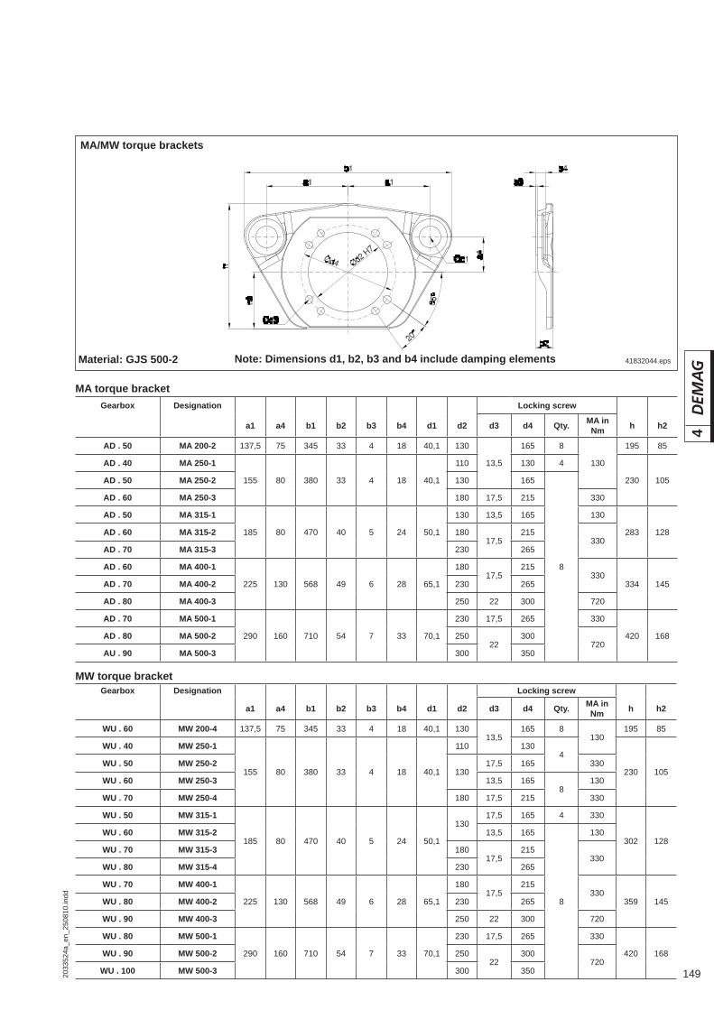
1492033
524a
_en_
2508
10.in
dd
4
MA/MW torque brackets
41832044.eps
MA torque bracket
MW torque bracket
Material: GJS 500-2
Gearbox Designation Locking screw
a1 a4 b1 b2 b3 b4 d1 d2 d3 d4 Qty. MA in Nm h h2
AD . 50 MA 200-2 137,5 75 345 33 4 18 40,1 130
13,5
165 8
130
195 85
AD . 40 MA 250-1
155 80 380 33 4 18 40,1
110 130 4
230 105AD . 50 MA 250-2 130 165
8
AD . 60 MA 250-3 180 17,5 215 330
AD . 50 MA 315-1
185 80 470 40 5 24 50,1
130 13,5 165 130
283 128AD . 60 MA 315-2 18017,5
215330
AD . 70 MA 315-3 230 265
AD . 60 MA 400-1
225 130 568 49 6 28 65,1
18017,5
215330
334 145AD . 70 MA 400-2 230 265
AD . 80 MA 400-3 250 22 300 720
AD . 70 MA 500-1
290 160 710 54 7 33 70,1
230 17,5 265 330
420 168AD . 80 MA 500-2 25022
300720
AU . 90 MA 500-3 300 350
Gearbox Designation Locking screw
a1 a4 b1 b2 b3 b4 d1 d2 d3 d4 Qty. MA in Nm h h2
WU . 60 MW 200-4 137,5 75 345 33 4 18 40,1 13013,5
165 8130
195 85
WU . 40 MW 250-1
155 80 380 33 4 18 40,1
110 1304
230 105WU . 50 MW 250-2
13017,5 165 330
WU . 60 MW 250-3 13,5 1658
130
WU . 70 MW 250-4 180 17,5 215 330
WU . 50 MW 315-1
185 80 470 40 5 24 50,1
13017,5 165 4 330
302 128WU . 60 MW 315-2 13,5 165
8
130
WU . 70 MW 315-3 18017,5
215330
WU . 80 MW 315-4 230 265
WU . 70 MW 400-1
225 130 568 49 6 28 65,1
18017,5
215330
359 145WU . 80 MW 400-2 230 265
WU . 90 MW 400-3 250 22 300 720
WU . 80 MW 500-1
290 160 710 54 7 33 70,1
230 17,5 265 330
420 168WU . 90 MW 500-2 25022
300720
WU . 100 MW 500-3 300 350
Note: Dimensions d1, b2, b3 and b4 include damping elements

150 2033
524a
_en_
2508
10.in
dd
4
4.2 MA/MW torque bracket set
1) Part no. includes depending on type torque bracket, bolted fastening parts and retaining elements2) Check drive shafts fi tted into hollow shafts for tight fi t.
DRS wheel block size Gearbox Designation
Part no. 1)
Top connection Side connection Pin connection D2 torque bracket 2)
KW B
notpermissible
112
AM . 10/20 MA112-1 753 796 44 753 797 44
WU . 10 MW112-1 753 890 44 753 892 44
WU . 20 MW112-2 753 891 44 753 894 44
125
AM . 10/20 MA125-1 752 396 44 752 397 44
AM . 30 MA125-2 752 39144 752 394 44
WU . 10 MW125-1 752 490 44 752 492 44
WU . 20/30 MW125-2 752 49144 752 494 44
160
AM . 20 MA160-1 752 696 44 752 697 44
AM . 30/40 MA160-2 752 69144 752 694 44
WU . 20/30 MW160-1 752 790 44 752 792 44
WU . 40 MW160-2 752 79144 752 794 44
200
AM . 30/40 MA200-1 753 190 44 753 192 44
AD . 50 MA200-2 753 191 44 753 193 44
WU . 30 MW200-1 753 290 44 753 293 44
WU . 40 MW200-2 753 291 44 753 294 44
WU . 50 MW200-3 753 292 44 753 295 44
WU . 60 MW200-4 753 296 44 753 297 44
250
AD . 40 MA250-1 753 490 44 753 570 44 818 649 44
AD . 50 MA250-2 753 49144 753 57144 811 208 44
AD . 60 MA250-3 753 492 44 753 572 44 787 989 44
WU . 40 MW250-1 753 590 44 753 580 44 -
WU . 50 MW250-2 753 591 44 753 581 44 -
WU . 60 MW250-3 753 592 44 753 582 44 -
WU . 70 MW250-4 753 593 44 753 583 44 -
315
AD . 50 MA315-1 754 190 44 754 270 44 811 208 44
AD . 60 MA315-2 754 19144 754 271 44 787 989 44
AD . 70 MA315-3 754 192 44 754 272 44 787 990 44
WU . 50 MW315-1 754 290 44 754 280 44 -
WU . 60 MW315-2 754 291 44 754 281 44 -
WU . 70 MW315-3 754 292 44 754 282 44 -
WU . 80 MW315-4 754 293 44 754 283 44 -
400
AD . 60 MA400-1 754 490 44 754 570 44 787 989 44
AD . 70 MA400-2 754 49144 754 57144 787 990 44
AD . 80 MA400-3 754 492 44 754 572 44 787 991 44
WU . 70 MW400-1 754 590 44 754 580 44 -
WU . 80 MW400-2 754 591 44 754 581 44 -
WU . 90 MW400-3 754 592 44 754 582 44 -
500
AD . 70 MA500-1 754 790 44 754 870 44 787 990 44
AD . 80 MA500-2 754 791 44 754 871 44 787 991 44
AU . 90 MA500-3 754 792 44 754 872 44 787 995 44
WU . 80 MW500-1 754 890 44 754 880 44 -
WU . 90 MW500-2 754 891 44 754 881 44 -
WU . 100 MW500-3 754 892 44 754 882 44 -

1512033
524a
_en_
2508
10.in
dd
4
h4
u
a
h2
f
h1
d
h2
df
h1
gf
h2
h1h1
d
Data for connection to the support structure
Set nut, grade 8
1) To fl ange contact surface2) Tolerance due to torque bracket slot3) Check drive shafts fi tted into hollow shafts for tight fi t.
41805946.eps
Washer, DIN 6919
Bolt, DIN 933
Detail X
Gea
rbox
cen
tre
Bor
e ho
le a
rran
gem
ent
cent
re
Gea
rbox
cen
tre
Gea
rbox
cen
tre
2)
1), 2)
4.3 D2 torque bracket
A 90A 70 - A 80A 40 - A 60 X
Gearbox Torque bracket Fastening bolts grade 10.9 Bore hole template3)
Part no. Size Qty. Tightening torque d H11 f ±0,3 g h1 h2 h4 a± 2) u± 1), 2)
AU/AD 40 818 649 44 M 12 4 115 Nm 14 35 – 25 20,5 206 91,5 ± 4 30 ± 4
AU/AD 50 811 208 44 M 16 4 300 Nm 18 65 – 60 20 255 140 ± 6 54,5 ± 6
AU/AD 60 787 989 44 M 16 4 300 Nm 18 100 – 60 83 309 120 ± 12 73 ± 12
AU/AD 70 787 990 44 M 16 6 300 Nm 18 100 – 60 83 366 120 ± 12 68,5 ± 12
AU/AD 80 787 991 44 M 16 6 300 Nm 18 100 – 60 83 440 118 ± 12 64,5 ± 12
AU 90 787 995 44 M 16 8 300 Nm 18 90 184 40 10 520 159 ± 12 93 ± 12

152 2033
524a
_en_
2508
10.in
dd
4
AU/AD . 40 gearbox
82 163
25
17
2060
145
45
135
65
200 Nm
49,5
177
63
39
13560
41037943.eps
AU/AD . 50 gearbox
AU/AD . 60 gearbox
41759544.eps
AU/AD . 70 gearbox
AU/AD . 80 gearbox AU . 90 gearbox
M
28
180
550 Nm 159
220
205
49
1841890
70
29
100
20
1040
80
41759444.eps
41759546.eps
41759545.eps
41037843.eps

1532033
524a
_en_
2508
10.in
dd
4
4.4 Buffers Buffers with a high energy absorption capacity are required to prevent any critical deformation in structural steelwork resulting from travel units colliding with each other or with the end of a track. For cellular foam and rubber buffers, the complete volume of the buffer is utilised as pressure is distributed over the whole section of the buffer. Lateral deformation remains low even under maximum compression. The favourable diameter-to-length ratio of this buffer ensures that any displace-ment of the buffers due to play in the guidance of the crane rails has no adverse effect.
For buffer impact special load situations, it is assumed that cranes, crabs and travel carriages, etc. only rarely collide in normal operation. The required buffer energy absorption capacity must be calculated:• for the maximum possible buffer impact speed, however, at least k = 70 % of
the travel speed, if speed reduction devices are fi tted• with k = 85 % of the travel speed for cranes• with k = 100 % of the travel speed for crabs, travel carriages, etc.
(k = buffer energy factor)
For an impact between two installations with identical buffers, calculate:• mass acting on the buffer mpu
Masses acting on the buffer are the masses acting on the corresponding part of the buffer depending on the distribution of masses of the structure when the buffer is impacted. The masses acting on cellular and rubber buffers (DPZ, DPG) can be doubled when a counterpart buffer of the same size is used.
mpu = mass acting on the buffermpu1 ... mpu2 = mass acting on the buffers of installations 1 and 2
• Travel speed
v = Travel speedv1 ... v2 = Individual impact speeds of installations 1 and 2
4.4.1 Buffer dimensions
mpu = mpu1 · mpu2
mpu1 + mpu2
v = l v1 l + l v2 l

154 2033
524a
_en_
2508
10.in
dd
4
Due to its excellent physical qualities as regards elasticity, cushioning and energy absorption, the cellular polyurethane material is particularly well suited for buffers. The buffer material is chemically resistant to ozone, oxygen, water, petrol and most oils and industrial greases. The buffer is fully functional at operating temperatures of – 20° C to + 80° C. In conditions of high humidity in conjunction with high tem-peratures, the rubber buffer should be used.
4.4.2 DPZ cellular plastic buffer
4.4.3 DPG rubber buffer The damping material consists of compact elastic rubber. This material has differ-ent characteristics to that of the cellular plastic buffers. This buffer material should preferably be used under conditions of high humidity. The buffer is fully functional at operating temperatures of – 30° C to + 70° C.
DPZ cellular plastic buffer – masses acting on the buffer
Cellular foam buffer Travel speed in m/min
Limit switch k=70% to 14,3 to 17,9 to 22,9 to 28,6 to 35,7 to 45,0 to 57,1 to 71,4 to 90,0 to 114,3 to 142,9 to 178,6 to 228,6
Long travel k=85% to 11,8 to 14,7 to 18,8 to 23,5 to 29,4 to 37,1 to 47,1 to 58,8 to 74,1 to 94,1 to 117,6 to 147,1 to 188,2
Cross travel k=100% to 10,0 to 12,5 to 16,0 to 20,0 to 25,0 to 31,5 to 40,0 to 50,0 to 63,0 to 80,0 to 100,0 to 125,0 to 160,0
DRS wheel block size Buffer max. mass which can be buffered in kg without counterbuffer
112 – 500 DPZ 70 6400 4170 2600 1710 1120 730 480
112 – 500 DPZ 100 22230 14500 9080 5980 2960 2610 1710 1160
160 – 500 DPZ 130 48480 31670 19660 12900 8500 5560 3610 2460
200 – 500 DPZ 160 87300 66760 34720 22740 14960 9760 6330 4270
315 – 500 DPZ 210 130140 84730 67730 34560 22760 14780 9660 6500 7360
With counterbuffer:The maximum mass which can be buffered is doubled when a counterbuffer of the same size is used. Masses acting on the buffer are the masses acting on the corresponding part of the buffer depending on the distribution of masses of the structure when the buffer is impacted. The masses acting on cellular and rubber buffers (DPZ, DPG) can be doubled when a counterpart buffer of the same size is used.The values given in the table are the maximum masses which can be buffered. It must be considered that deceleration must not exceed 3 g.
DPG rubber buffer – masses acting on the buffer
Rubber buffer Travel speed in m/min
Limit switch k=70% to 14,3 to 17,9 to 22,9 to 28,6 to 35,7 to 45,0 to 57,1 to 71,4 to 90,0 to 114,3 to 142,9 to 178,6 to 228,6
Long travel k=85% to 11,8 to 14,7 to 18,8 to 23,5 to 29,4 to 37,1 to 47,1 to 58,8 to 74,1 to 94,1 to 117,6 to 147,1 to 188,2
Cross travel k=100% to 10,0 to 12,5 to 16,0 to 20,0 to 25,0 to 31,5 to 40,0 to 50,0 to 63,0 to 80,0 to 100,0 to 125,0 to 160,0
DRS wheel block size Buffer max. mass which can be buffered in kg without counterbuffer
112 – 500 DPG 63 17490 11190 6830 4370 2790 1760 1090 690
112 – 125DPG 80
27360 17510 10680 6840 4370 2750 1710 1090
160 – 500 36000 23040 14060 9000 5760 3620 2250 1440
160 – 200DPG 100
66600 42620 26010 16650 10650 6710 4160 2660 1670
250 – 500 72000 460080 28120 18000 11520 7250 4500 2880 1810
250 – 315DPG 160
136080 87090 53150 34020 21770 13710 8500 5440 3420
315 – 500 193680 123950 75650 48420 30980 19510 12100 7740 4870
315 – 500DPG 200
280800 179710 109680 70200 44920 28290 17550 11230 7070
external 455760 291680 178030 113940 72920 45930 28480 18230 11480
With counterbuffer:The maximum mass which can be buffered is doubled when a counterbuffer of the same size is used.The values given in the table only apply for buffers when fi tted direct to the wheel block.The maximum masses which can be buffered by the given buffer may be used when fi tted to the connecting structure.The values given in the table (max. masses which can be buffered by the relevant buffer) apply for buffers when fi tted to the connecting structure and when fi tted direct to the wheel block.
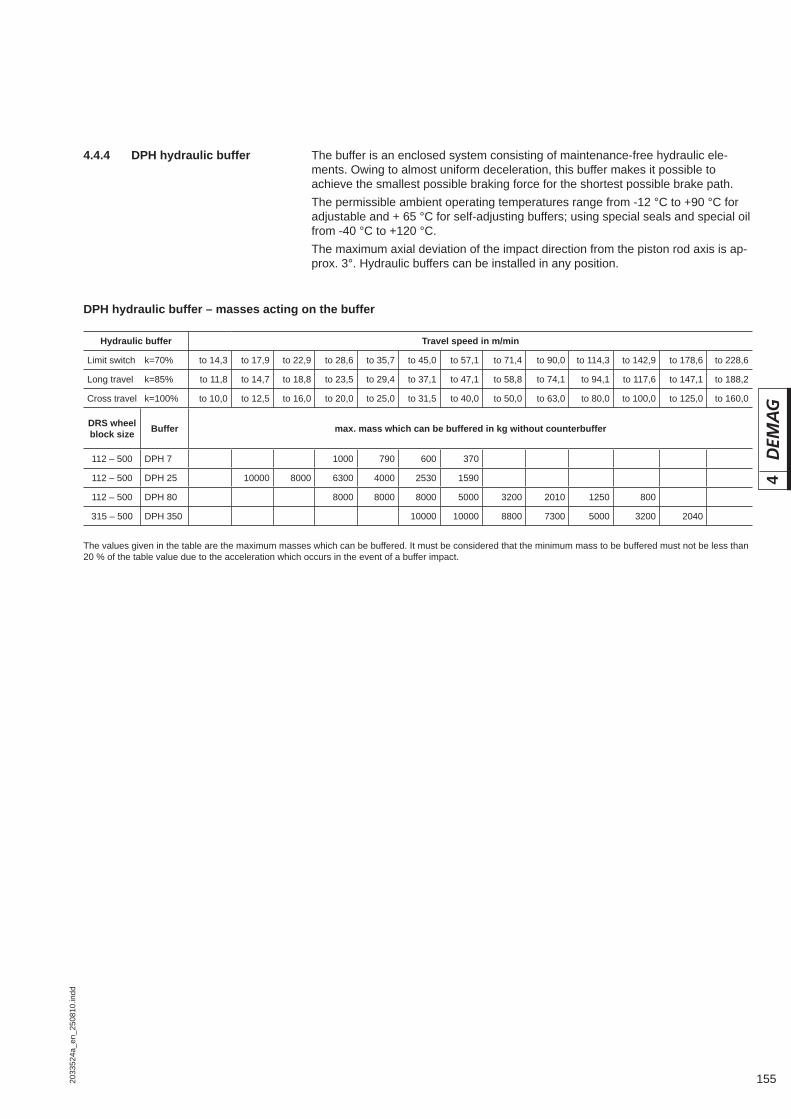
1552033
524a
_en_
2508
10.in
dd
4
4.4.4 DPH hydraulic buffer The buffer is an enclosed system consisting of maintenance-free hydraulic ele-ments. Owing to almost uniform deceleration, this buffer makes it possible to achieve the smallest possible braking force for the shortest possible brake path.The permissible ambient operating temperatures range from -12 °C to +90 °C for adjustable and + 65 °C for self-adjusting buffers; using special seals and special oil from -40 °C to +120 °C.The maximum axial deviation of the impact direction from the piston rod axis is ap-prox. 3°. Hydraulic buffers can be installed in any position.
DPH hydraulic buffer – masses acting on the buffer
Hydraulic buffer Travel speed in m/min
Limit switch k=70% to 14,3 to 17,9 to 22,9 to 28,6 to 35,7 to 45,0 to 57,1 to 71,4 to 90,0 to 114,3 to 142,9 to 178,6 to 228,6
Long travel k=85% to 11,8 to 14,7 to 18,8 to 23,5 to 29,4 to 37,1 to 47,1 to 58,8 to 74,1 to 94,1 to 117,6 to 147,1 to 188,2
Cross travel k=100% to 10,0 to 12,5 to 16,0 to 20,0 to 25,0 to 31,5 to 40,0 to 50,0 to 63,0 to 80,0 to 100,0 to 125,0 to 160,0
DRS wheel block size Buffer max. mass which can be buffered in kg without counterbuffer
112 – 500 DPH 7 1000 790 600 370
112 – 500 DPH 25 10000 8000 6300 4000 2530 1590
112 – 500 DPH 80 8000 8000 8000 5000 3200 2010 1250 800
315 – 500 DPH 350 10000 10000 8800 7300 5000 3200 2040
The values given in the table are the maximum masses which can be buffered. It must be considered that the minimum mass to be buffered must not be less than 20 % of the table value due to the acceleration which occurs in the event of a buffer impact.
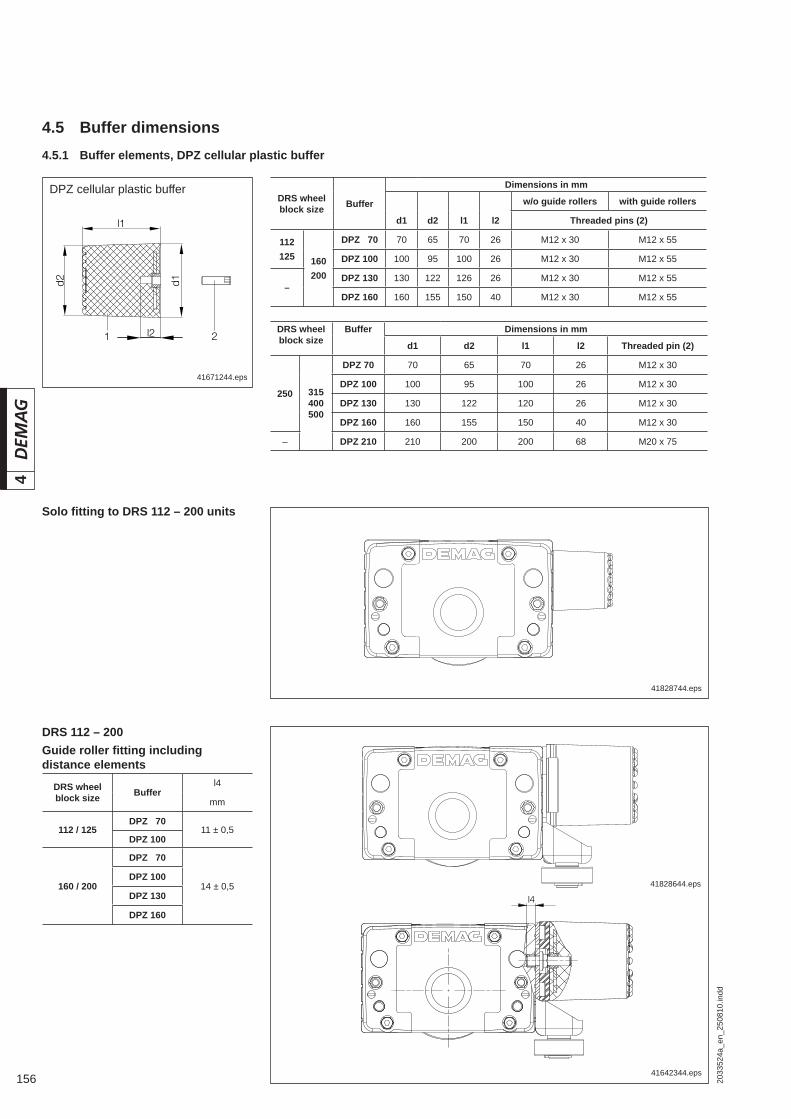
156 2033
524a
_en_
2508
10.in
dd
4
4.5.1 Buffer elements, DPZ cellular plastic buffer
41671244.eps
DPZ cellular plastic buffer
41828744.eps
41828644.eps
41642344.eps
Solo fi tting to DRS 112 – 200 units
DRS 112 – 200Guide roller fi tting including distance elements
4.5 Buffer dimensions
DRS wheel block size Buffer
Dimensions in mm
w/o guide rollers with guide rollers
d1 d2 l1 l2 Threaded pins (2)
112125 160
200
DPZ 070 70 65 70 26 M12 x 30 M12 x 55
DPZ 100 100 95 100 26 M12 x 30 M12 x 55
–DPZ 130 130 122 126 26 M12 x 30 M12 x 55
DPZ 160 160 155 150 40 M12 x 30 M12 x 55
DRS wheel block size
Buffer Dimensions in mm
d1 d2 l1 l2 Threaded pin (2)
250 315400500
DPZ 70 70 65 70 26 M12 x 30
DPZ 100 100 95 100 26 M12 x 30
DPZ 130 130 122 120 26 M12 x 30
DPZ 160 160 155 150 40 M12 x 30
– DPZ 210 210 200 200 68 M20 x 75
DRS wheel block size Buffer
l4
mm
112 / 125DPZ 070
11 ± 0,5DPZ 100
160 / 200
DPZ 070
14 ± 0,5DPZ 100
DPZ 130
DPZ 160

1572033
524a
_en_
2508
10.in
dd
4
To ensure uniform buffer impact with a horizontal guide roller arrangement fi tted to only one wheel block, type E1/E2 spacers must be fi tted between the buffer and wheel block on the opposite side.
41642544.eps
DRS 112 – 125 – 160 – 200
Buffer set part no.
DRS wheel block size Buffer Solo fi tting to DRS or connecting
structure w/o distance elementCompensating side incl. distance
elementGuide roller arrangement incl. dis-
tance element
112125
160200
DPZ 070 860 810 46 1) 860 812 46 2) 860 811 46 3)
DPZ 100 860 814 46 1) 860 816 46 2) 860 815 46 3)
–DPZ 130 860 818 46 1) 860 820 46 2) 860 819 46 3)
DPZ 160 860 822 46 1) 860 824 46 2) 860 823 46 3)
DRS 250 – 315 – 400 – 500
42017444.eps
Stop
Stop
Buffer set part no.
DRS wheel block size Buffer Solo fi tting to DRS or connecting
structure w/o distance element
250 315400500
DPZ 70 860 810 46 1)
DPZ 100 860 814 46 1)
DPZ 130 860 818 46 1)
DPZ 160 860 822 46 1)
– DPZ 210 860 826 46 1)
1) Part no. includes buffer and threaded pin2) Part no. includes buffer, threaded pin and distance element3) Part no. includes buffer, nut and distance element4) Only one type E2 spacer required.
DRS wheel block size Buffer
Spacer elements
E1 E2
s1 Part no. s2 Part no.
112125
160200
DPZ 070 14 752 003 44 10 752 002 44
DPZ 100 20 752 005 44 12,5 752 004 44
–DPZ 130 25 752 007 44 16 752 006 44
DPZ 160 4) 15 752 00844 21 752 009 44
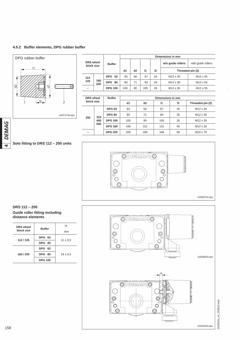
158 2033
524a
_en_
2508
10.in
dd
4
41671744.eps
DPG rubber buffer
41828744.eps
41828644.eps
41642344.eps
Solo fi tting to DRS 112 – 200 units
DRS 112 – 200Guide roller fi tting including distance elements
DRS wheel block size Buffer
l4
mm
112 / 125DPG 063
11 ± 0,5DPG 080
160 / 200
DPG 063
14 ± 0,5DPG 080
DPG 100
4.5.2 Buffer elements, DPG rubber buffer
DRS wheel block size
Buffer Dimensions in mm
d1 d2 l1 l2 Threaded pin (2)
250 315400500
DPG 63 63 56 67 26 M12 x 30
DPG 80 80 71 84 26 M12 x 30
DPG 100 100 90 105 26 M12 x 30
DPG 160 160 151 131 40 M12 x 30
– DPG 200 200 189 166 58 M20 x 75
DRS wheel block size Buffer
Dimensions in mm
w/o guide rollers with guide rollers
d1 d2 l1 l2 Threaded pin (2)
112125 160
200
DPG 063 063 56 067 26 M12 x 30 M12 x 55
DPG 080 080 71 084 26 M12 x 30 M12 x 55
– DPG 100 100 90 105 26 M12 x 30 M12 x 55
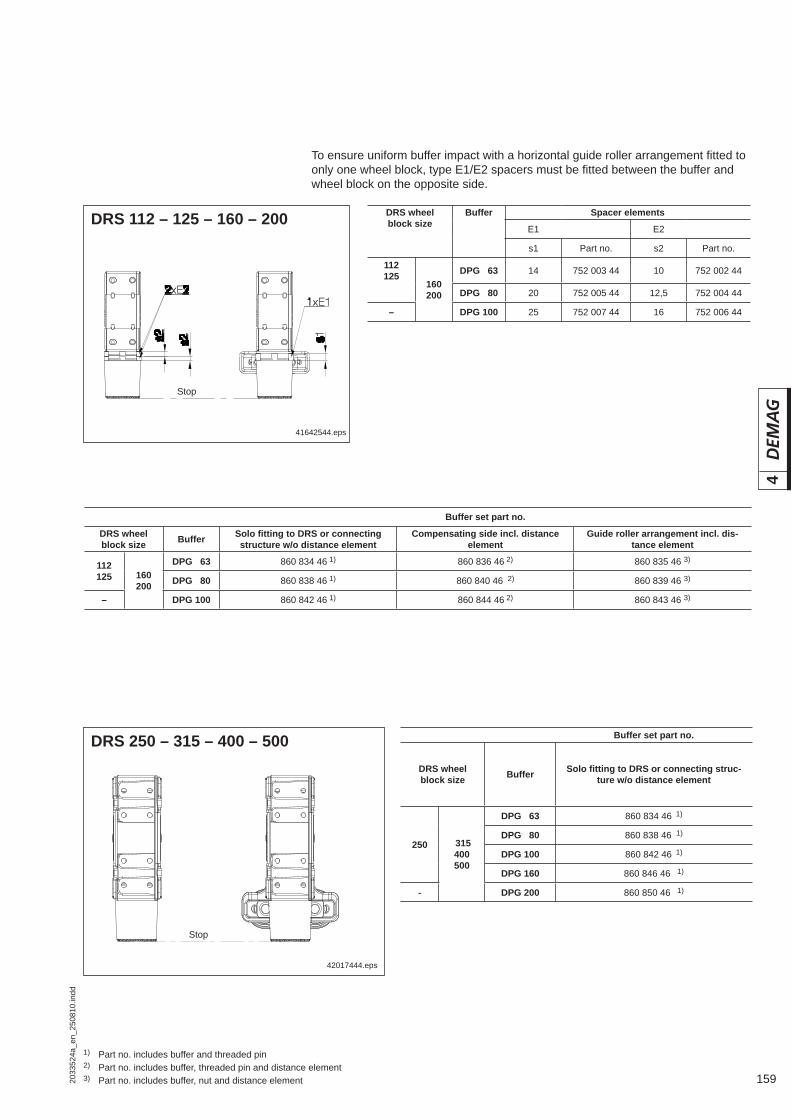
1592033
524a
_en_
2508
10.in
dd
4
To ensure uniform buffer impact with a horizontal guide roller arrangement fi tted to only one wheel block, type E1/E2 spacers must be fi tted between the buffer and wheel block on the opposite side.
Buffer set part no.
DRS wheel block size Buffer Solo fi tting to DRS or connecting
structure w/o distance elementCompensating side incl. distance
elementGuide roller arrangement incl. dis-
tance element
112125 160
200
DPG 063 860 834 46 1) 860 836 46 2) 860 835 46 3)
DPG 080 860 838 46 1) 860 840 46 2) 860 839 46 3)
– DPG 100 860 842 46 1) 860 844 46 2) 860 843 46 3)
41642544.eps
42017444.eps
Stop
Stop
DRS 112 – 125 – 160 – 200
DRS 250 – 315 – 400 – 500
1) Part no. includes buffer and threaded pin2) Part no. includes buffer, threaded pin and distance element3) Part no. includes buffer, nut and distance element
Buffer set part no.
DRS wheel block size Buffer Solo fi tting to DRS or connecting struc-
ture w/o distance element
250 315400500
DPG 063 860 834 46 1)
DPG 080 860 838 46 1)
DPG 100 860 842 46 1)
DPG 160 860 846 46 1)
- DPG 200 860 850 46 1)
DRS wheel block size
Buffer Spacer elements
E1 E2
s1 Part no. s2 Part no.
112125
160200
DPG 063 14 752 003 44 10 752 002 44
DPG 080 20 752 005 44 12,5 752 004 44
– DPG 100 25 752 007 44 16 752 006 44

160 2033
524a
_en_
2508
10.in
dd
4
4.5.3 DPH hydraulic bufferStandard installation variant with adapter, threaded pin and set nut suitable for fi tting to the connecting structure
Mounting variant IIFoot or neck mounting confi guration
41546802.eps41546801.eps
Standard mounting variant with adapter
1) Part no. includes hydraulic buffer, nut, adapter, threaded pin and set nut2) Second nut required for installation variant II for foot or neck mounting confi guration
Size
Energy absorption eff. mass
Hydraulic buffer Adapter Pin Part no.Stroke Length Thread Weight 1)
Epu mpu H l1 d3 l3 d2 M l l2[Nm] [kg] [kg]
DPH 7self-adjust-
ing68
113+
113025,4 149,9
2)
M 25 x 1,5 102 23 0,26 M 12 167 40 811 294 44
DPH 25adjustable 230
500+
800050,8 189 UNF1¼
- 12 17 25,4 0,76 M 12 207 40 811 295 44
DPH 80adjustable 780
54+
950076 246 UNF1¾
- 12 23 38 2,1 M 12 267 40 811 296 44
DPH 350self-adjust-
ing3390
1360+
6800152 450
4)
M 64 x 2 38 60 4,7 M 20 478 40 811 297 44 N

1612033
524a
_en_
2508
10.in
dd
4

162 2033
524a
_en_
2508
10.in
dd
4
4.6.1 General • Wheel blocks with fl ange guide arrangement The permissible horizontal force on fl ange-guided wheel blocks must not ex-
ceed 20 % of the actual wheel load.• Wheel blocks with roller guide arrangement The permissible horizontal force on wheel blocks fi tted with a roller guide ar-
rangement must not exceed 15 % of the actual wheel load. For DRS 112 – DRS 200 with travel wheel variant E, the value must be limited to 12 %.
Exception: DRS 200 with top connection, the permissible horizontal force must be limited to 10% of the actual wheel load. If higher horizontal loads are to be expected, the roller guide arrangement can be fi tted to the steel superstructure, however, not to the wheel block.
• Wheel blocks with roller guide arrangement, fi tted to the customer’s su-perstructure
The guide roller arrangement as a solo part may transmit 20 % of the actual wheel load when fi tted to the customer’s superstructure.
Guide rollers must not be used with rails that have sloping head fl ank surfaces.Ordering information:If a guide roller arrangement is specifi ed in the type key when ordering a single wheel block, this is prepared for fi tting before leaving the factory.Attention! For fi tting the horizontal guide roller arrangement, make sure it is suit-able for application in conjunction with the rail fastening (see chapter 2.7) and the type of rail. See chapter 2.7.5 for fl at rails and chapter 2.7.6 for crane rails.
4.6 Guide rollers
s s
42015744.eps
k = Rail width
DRS 112 – 125 – 160 DRS 200
41641644.eps
4.6.2 Horizontal guide rollers DRS 112 – 200
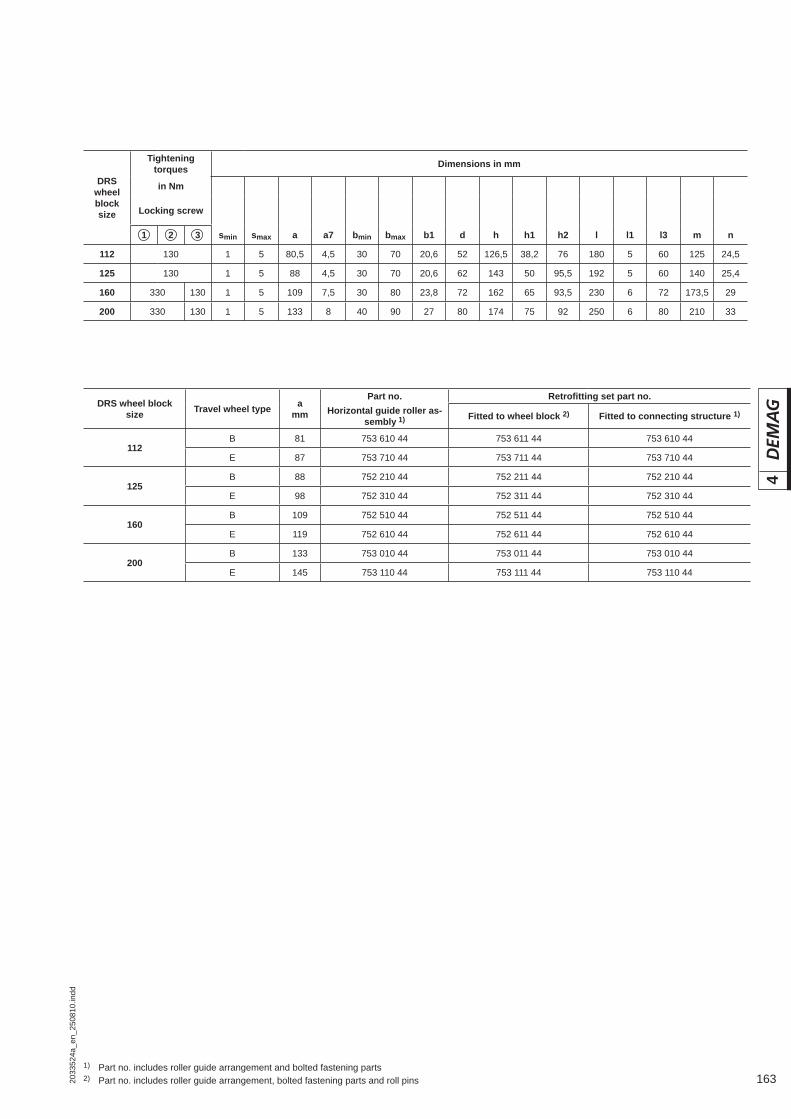
1632033
524a
_en_
2508
10.in
dd
4
DRS wheel block size Travel wheel type a
mm
Part no. Retrofi tting set part no.Horizontal guide roller as-
sembly 1) Fitted to wheel block 2) Fitted to connecting structure 1)
112B 81 753 610 44 753 611 44 753 610 44
E 87 753 710 44 753 711 44 753 710 44
125B 88 752 210 44 752 211 44 752 210 44
E 98 752 310 44 752 311 44 752 310 44
160B 109 752 510 44 752 511 44 752 510 44
E 119 752 610 44 752 611 44 752 610 44
200B 133 753 010 44 753 011 44 753 010 44
E 145 753 110 44 753 111 44 753 110 44
1) Part no. includes roller guide arrangement and bolted fastening parts2) Part no. includes roller guide arrangement, bolted fastening parts and roll pins
DRS wheel block size
Tightening torques Dimensions in mm
in Nm
Locking screw
1 2 3 smin smax a a7 bmin bmax b1 d h h1 h2 l l1 l3 m n
112 130 1 5 80,5 4,5 30 70 20,6 52 126,5 38,2 76 180 5 60 125 24,5
125 130 1 5 88 4,5 30 70 20,6 62 143 50 95,5 192 5 60 140 25,4
160 330 130 1 5 109 7,5 30 80 23,8 72 162 65 93,5 230 6 72 173,5 29
200 330 130 1 5 133 8 40 90 27 80 174 75 92 250 6 80 210 33
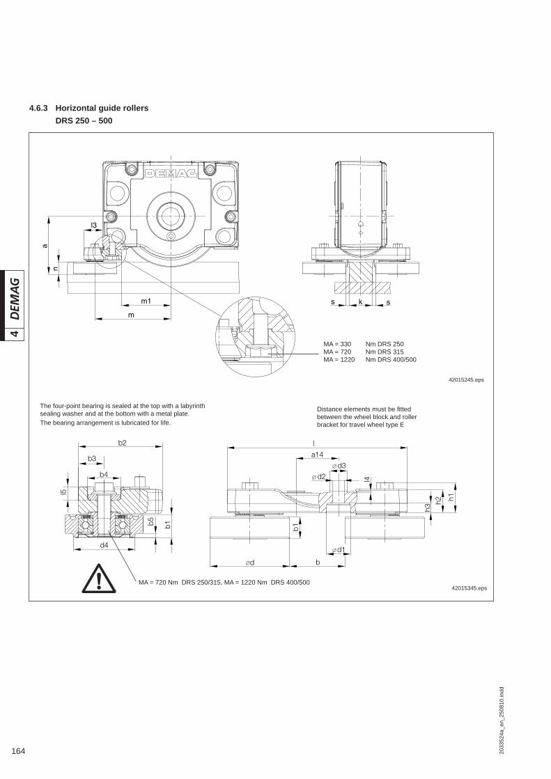
164 2033
524a
_en_
2508
10.in
dd
4
n
a
l3
m1
m
ks s
4.6.3 Horizontal guide rollers DRS 250 – 500
bd
b1
d1
l
a14
d2d3
l4
h3h2 h1
b2
b4
b3
d4
l5
b1b5
42015245.eps
MA = 330 Nm DRS 250MA = 720 Nm DRS 315MA = 1220 Nm DRS 400/500
42015345.epsMA = 720 Nm DRS 250/315, MA = 1220 Nm DRS 400/500
Distance elements must be fi tted between the wheel block and roller bracket for travel wheel type E
The four-point bearing is sealed at the top with a labyrinth sealing washer and at the bottom with a metal plate.The bearing arrangement is lubricated for life.

1652033
524a
_en_
2508
10.in
dd
4
DRS wheel block size
Dimensions in mm
smin smax a a7 kmin kmax bmin bmax b1 b2 b3 b4 b5 d d1
250 1 5 163 2,8 25 88 30 90 34 130 40 51 6 120 36
315 1 5 200 4,5 35 98 40 100 40 130 37,5 51 - 150 42
400 1 5 246 4 55 115 60 120 44,5 158 45 61 6 180 58
500 1 5 297 4 75 155 80 160 50 180 50 61 7 220 58
DRS wheel block size
Dimensions in mm
d2 d3 d4 h1 h2 h3 l a14 ± 0,2 l3 l4 l5 m m1 n
250 18 30 g6 95 46 40 15 296 70 65,5 3,5 20 218 128 38
315 22 32 g6 - 58,5 46,5 18 340 80 65 3,5 14 262,5 170 42,5
400 26 44 g6 140 66,5 53,5 19 400 100 76 3,5 14 321 208 46
500 26 54 g6 165 74 61 19 490 110 80 4,5 14 380 250 47
DRS wheel block size
Travel wheel type a Retrofi tting set part no.
mm Fitted to wheel block Fitted to connecting structure 3)
250B 163 753 311 44 1)
E 173 753 511 44 2)
315B 200 754 011 44 1)
E 212,5 754 211 44 2)
400B 246 754 311 44 1)
E 266 754 511 44 2)
500B 297 754 611 44 1)
E 317 754 811 44 2)
1) Part no. includes roller guide arrangement and bolted fastening parts2) Part no. includes roller guide arrangement, bolted fastening parts and distance element3) If the horizontal guide roller arrangement is not fi tted to the DRS wheel block, the corresponding connecting structure
must be provided with 2 counterpart bore holes: DRS 250 = dia. D30H8 DRS 315 = dia. D32H8
DRS 400 = dia. D44H8
DRS 500 = dia. D54H8
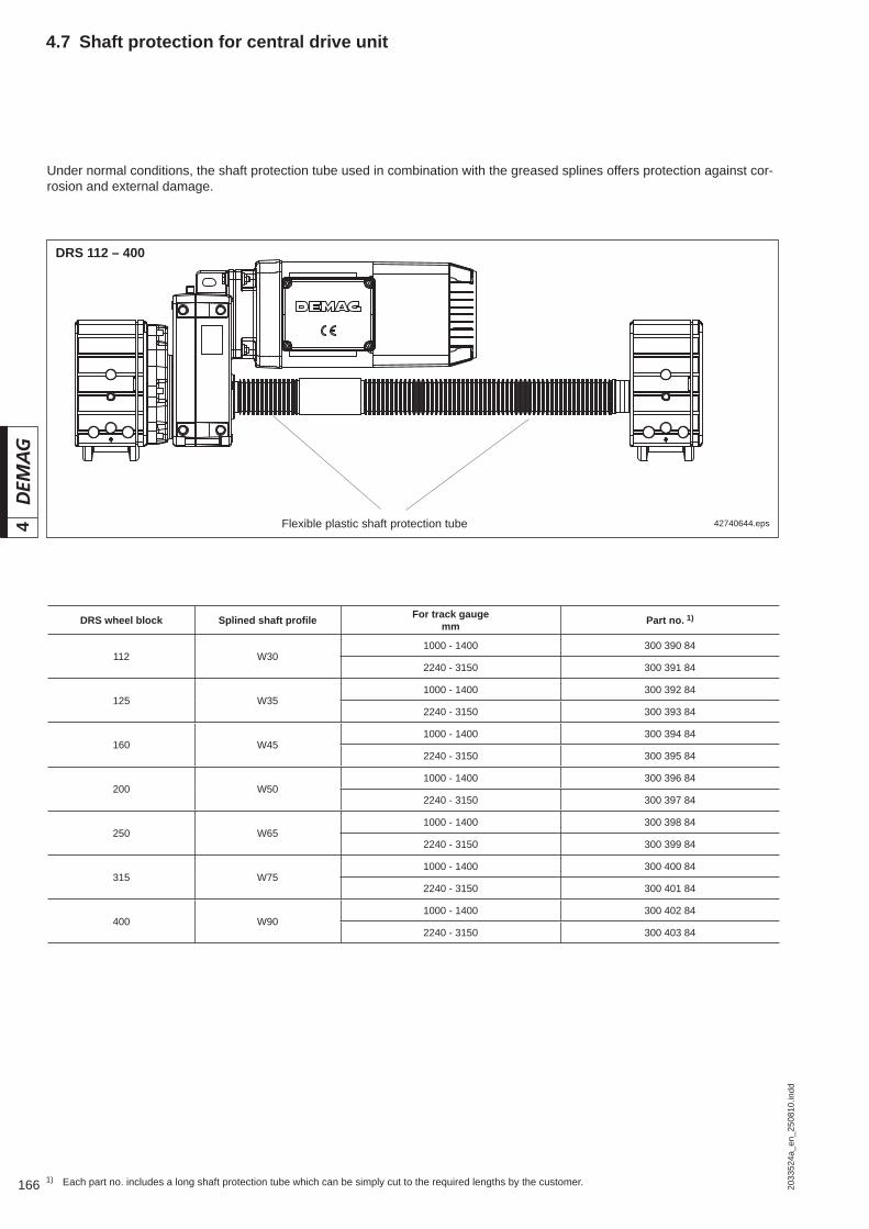
166 2033
524a
_en_
2508
10.in
dd
44.7 Shaft protection for central drive unit
42740644.eps
DRS 112 – 400
Flexible plastic shaft protection tube
1) Each part no. includes a long shaft protection tube which can be simply cut to the required lengths by the customer.
Under normal conditions, the shaft protection tube used in combination with the greased splines offers protection against cor-rosion and external damage.
DRS wheel block Splined shaft profi le For track gaugemm Part no. 1)
112 W301000 - 1400 300 390 84
2240 - 3150 300 391 84
125 W351000 - 1400 300 392 84
2240 - 3150 300 393 84
160 W451000 - 1400 300 394 84
2240 - 3150 300 395 84
200 W501000 - 1400 300 396 84
2240 - 3150 300 397 84
250 W651000 - 1400 300 398 84
2240 - 3150 300 399 84
315 W751000 - 1400 300 400 84
2240 - 3150 300 401 84
400 W901000 - 1400 300 402 84
2240 - 3150 300 403 84

1672033
524a
_en_
2508
10.in
dd
4
Relubrication on accessible side surfaces via screw-fi tted fl at nipple.
41832944.eps
Relubrication on inaccessible side surfaces, e.g. due to fi tted drive or superstructure. Lubrication nipple part no. 350 580 99 can be used for the accessible side.
41832744.eps
Relubrication on inaccessible side surfaces, e.g. due to side connection or similar connecting structures. Lubrication nipple part no. 350 580 99 can be used for the accessible side.
41832844.eps
Part no. 350 580 991)
Flat lubrication nippleAM10x1 DIN 3404
Part no. 752 910 441)
90° relubrication line with AM10x1 DIN 3404 fl at lubri-cation nipple (tube length 200 mm)
X
Detail X
Y
Detail Y
Part no. 752 911 441)
Straight relubrication line with AM10x1 DIN 3404 fl at lubrication nipple (tube length 200 mm)
1) Part no. contains complete lubrication unit including a tube clip to attach the lubricating line.
4.8.1 Relubrication of grooved ball bearings DRS 250 – 500
1) Part no. includes 1 off fl at lubrica-tion nipple
1) Part no. contains complete lubrication unit including a tube clip to attach the lubricating line.
Second fl at lubrica-tion nipple
4.8 Options

168 2033
524a
_en_
2508
10.in
dd
4
4.8.2 Friction bearings with double-lip sealing discs for DRS 112 – 200
Low-maintenance grooved ball bearings with double-lip sealing discs must be used for extremely dusty and damp operating conditions. Suitable for temperatures from -20° C to +110° C.
4.8.3 Travel wheels with hardened treads and wheel fl anges
For operating conditions in which increased wheel fl ange wear is likely (e.g. rails with extreme dirt accumulation), the running surfaces of the spheroidal graphite cast iron travel wheel fl anges can be specially hardened (penetration depth up to 3 mm). Hardening is then to 56 ± 2 HRc. This does not apply to fl anges turned at a later date beyond the standard tread, e.g. DRS 112 to 62 mm.
See section 1.8 for information.4.8.4.2 Special paint fi nishDRS 112 – 200
See section 1.8 for information.4.8.4.3 Special paint fi nishDRS 250 – 500
4.8.4.1 Acid-resistant paint fi nish DRS 112 – 500
See section 1.8 for information.
High-temperature grease, V sealing ring of Viton and relubrication opening closed with screws.
4.8.5 Temperatures + 70 ºC – + 150 ºCDRS 250 – 500
4.8.4 Special paint fi nish
If the wheel block is fi tted with the running surface facing upwards, the bore hole serves as a water drain opening, e.g. for operation outdoors.
4.8.6 Bore holes through top connection surface

1692033
524a
_en_
2508
10.in
dd
4
See section 1.9 for information on the aligning device.4.8.8 Aligning device
The on-board brush system largely keeps the rail clean. For fi tting the rail cleaning system, the wheel block must be prepared for fi tting horizontal guide rollers, i.e. threaded inserts on the end face are required. The rail-cleaning system can also be fi tted in combination with a buffer bracket. The maximum buffer size that can be fi tted to sizes DRS 125 - DRS 200 is DPZ 100 and DPG 100, respectively.The rail-cleaning system in combination with horizontal guide rollers is not possible.
4.8.7 Rail cleaning system
Wheel block Part no.
DRS 125 752 432 44
DRS 160 / 200 301 733 84
DRS 250 / 315 752 920 44
DRS 400 / 500 752 921 44
42772044.eps
DRS 125 - 200 DRS 250 - 500
42791444.eps

170 2033
525a
_en_
2508
10.in
dd
55 Demag DRS wheel block system Specifi cation
Duty factor
Number of cyclesA normal cycle is made up as shown in the following diagram, i.e. 1 x travel to the left – pause, 1 x travel to the right – pause, with 3 starts being assumed on aver-age for each travel motion.
The maximum number of cycles is calcu-lated from:
This equation applies on condition that the permissible number of starts is not exceeded.
S = Number of cycles per hour, cycle according to diagram, one or two speeds
CDF = Relative duty factor in %v = Travel speed in m/minL = Travel path (single) with travel
motor switched on in m
5.1 Travel drives5.1.1 Number of cycles, relative
duty factor and starting frequency
41631544.eps
Duty factor
PauseLoad time
Duration of cycle
Single-speed drive
41629244.eps
V
1 2 3 4 5 6
Travel to left Pause Travel to right Pause
Cycle
Drive with two speeds
41629344.eps
V
1 2 3 4 5 6
PauseTravel to left Travel to right Pause
Cycle
S ≈ 0,3 · CDF · v
L
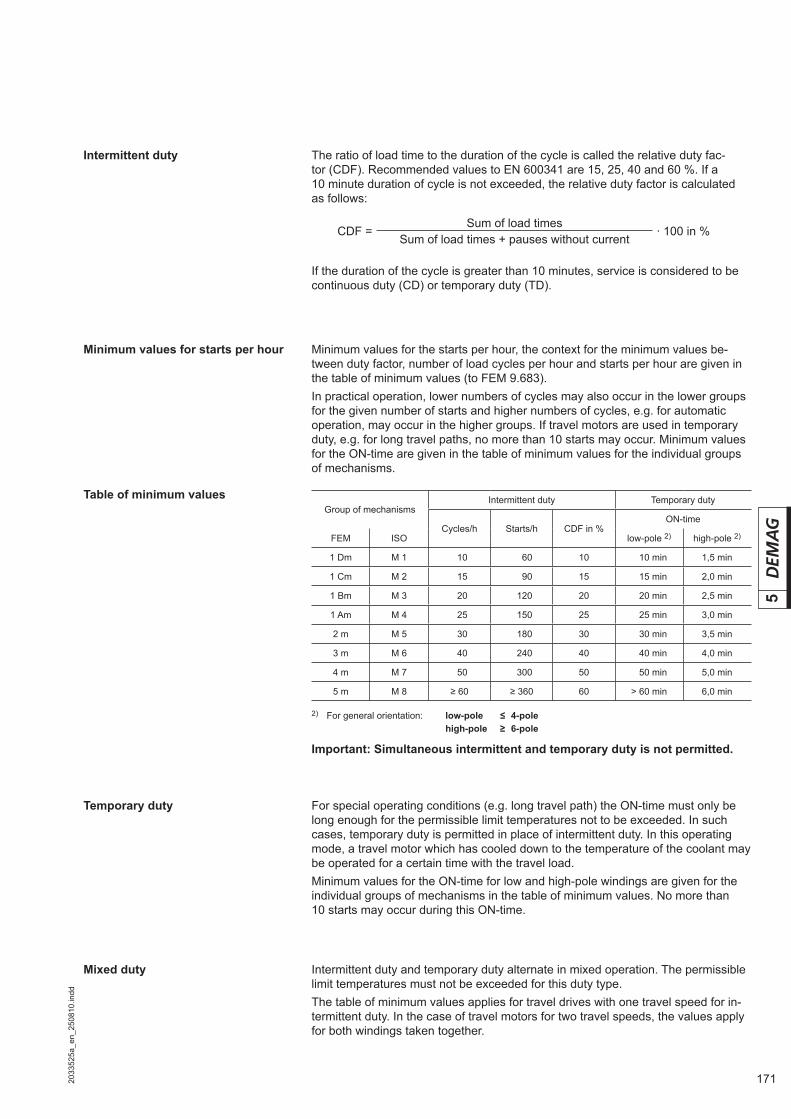
1712033
525a
_en_
2508
10.in
dd
5
The ratio of load time to the duration of the cycle is called the relative duty fac-tor (CDF). Recommended values to EN 600341 are 15, 25, 40 and 60 %. If a 10 minute duration of cycle is not exceeded, the relative duty factor is calculated as follows:
If the duration of the cycle is greater than 10 minutes, service is considered to be continuous duty (CD) or temporary duty (TD).
Minimum values for the starts per hour, the context for the minimum values be-tween duty factor, number of load cycles per hour and starts per hour are given in the table of minimum values (to FEM 9.683).In practical operation, lower numbers of cycles may also occur in the lower groups for the given number of starts and higher numbers of cycles, e.g. for automatic operation, may occur in the higher groups. If travel motors are used in temporary duty, e.g. for long travel paths, no more than 10 starts may occur. Minimum values for the ON-time are given in the table of minimum values for the individual groups of mechanisms.
Minimum values for starts per hour
Table of minimum values
Important: Simultaneous intermittent and temporary duty is not permitted.
For special operating conditions (e.g. long travel path) the ON-time must only be long enough for the permissible limit temperatures not to be exceeded. In such cases, temporary duty is permitted in place of intermittent duty. In this operating mode, a travel motor which has cooled down to the temperature of the coolant may be operated for a certain time with the travel load.Minimum values for the ON-time for low and high-pole windings are given for the individual groups of mechanisms in the table of minimum values. No more than 10 starts may occur during this ON-time.
Temporary duty
Intermittent duty and temporary duty alternate in mixed operation. The permissible limit temperatures must not be exceeded for this duty type.The table of minimum values applies for travel drives with one travel speed for in-termittent duty. In the case of travel motors for two travel speeds, the values apply for both windings taken together.
Mixed duty
2) For general orientation: low-pole ≤ 4-pole high-pole ≥ 6-pole
Intermittent duty
Group of mechanismsIntermittent duty Temporary duty
Cycles/h Starts/h CDF in %ON-time
FEM ISO low-pole 2) high-pole 2)
1 Dm M 1 ³ 10 ³ 060 10 > 10 min 1,5 min
1 Cm M 2 ³ 15 ³ 090 15 > 15 min 2,0 min
1 Bm M 3 ³ 20 ³ 120 20 > 20 min 2,5 min
1 Am M 4 ³ 25 ³ 150 25 > 25 min 3,0 min
2 m M 5 ³ 30 ³ 180 30 > 30 min 3,5 min
3 m M 6 ³ 40 ³ 240 40 > 40 min 4,0 min
4 m M 7 ³ 50 ³ 300 50 > 50 min 5,0 min
5 m M 8 ≥ 60 ≥ 360 60 > 60 min 6,0 min
CDF =Sum of load times
· 100 in %Sum of load times + pauses without current
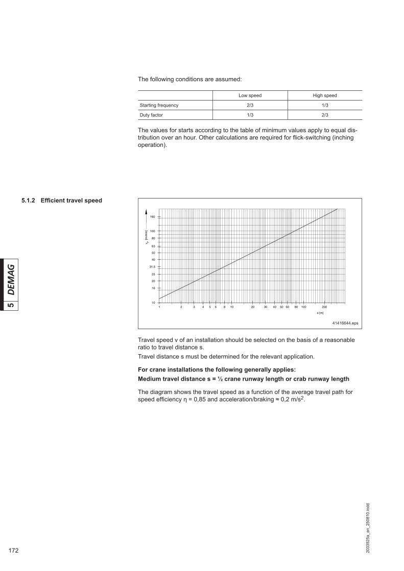
172 2033
525a
_en_
2508
10.in
dd
5
5.1.2 Effi cient travel speed
Travel speed v of an installation should be selected on the basis of a reasonable ratio to travel distance s. Travel distance s must be determined for the relevant application.
For crane installations the following generally applies:Medium travel distance s = ½ crane runway length or crab runway length
The diagram shows the travel speed as a function of the average travel path for speed effi ciency η = 0,85 and acceleration/braking ≈ 0,2 m/s2.
The following conditions are assumed:
The values for starts according to the table of minimum values apply to equal dis-tribution over an hour. Other calculations are required for fl ick-switching (inching operation).
1 2 3 4 5 6 8 10 20 30 40 50 60 80 100 20010
16
20
25
31,5
40
50
63
100
80
160
s [m]
[m/m
in]
v F
41416644.eps
Low speed High speed
Starting frequency 2/3 1/3
Duty factor 1/3 2/3
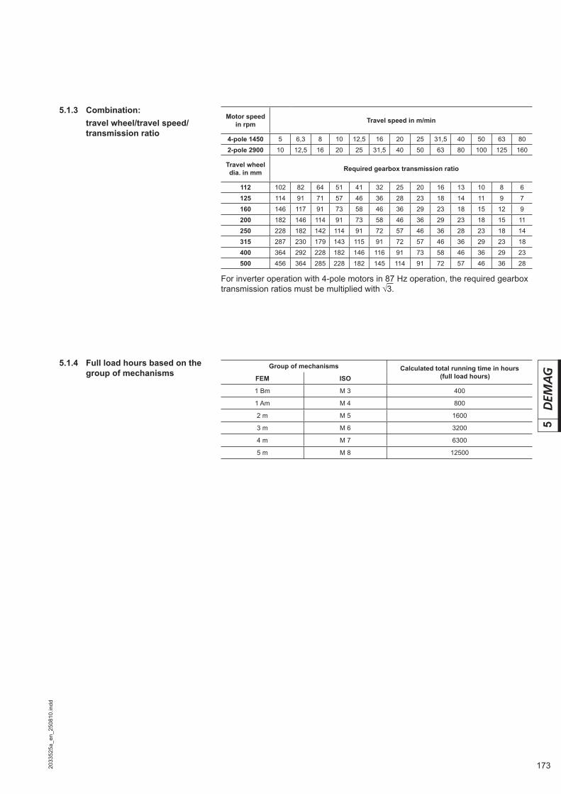
1732033
525a
_en_
2508
10.in
dd
5
5.1.3 Combination: travel wheel/travel speed/
transmission ratio
5.1.4 Full load hours based on the group of mechanisms
For inverter operation with 4-pole motors in 87 Hz operation, the required gearbox transmission ratios must be multiplied with √3.
Motor speed in rpm Travel speed in m/min
4-pole 1450 5 6,3 8 10 12,5 16 20 25 31,5 40 50 63 802-pole 2900 10 12,5 16 20 25 31,5 40 50 63 80 100 125 160
Travel wheel dia. in mm Required gearbox transmission ratio
112 102 82 64 51 41 32 25 20 16 13 10 8 6125 114 91 71 57 46 36 28 23 18 14 11 9 7160 146 117 91 73 58 46 36 29 23 18 15 12 9200 182 146 114 91 73 58 46 36 29 23 18 15 11250 228 182 142 114 91 72 57 46 36 28 23 18 14315 287 230 179 143 115 91 72 57 46 36 29 23 18400 364 292 228 182 146 116 91 73 58 46 36 29 23500 456 364 285 228 182 145 114 91 72 57 46 36 28
Group of mechanisms Calculated total running time in hours (full load hours)FEM ISO
1 Bm M 3 400
1 Am M 4 800
2 m M 5 1600
3 m M 6 3200
4 m M 7 6300
5 m M 8 12500

174 2033
525a
_en_
2508
10.in
dd
5
5.2.2 Hydropur travel wheels Travel wheels with Hydropur-elastomer rims 94 ±2 Shore “A”The traction resistance of travel wheels depends largely on the deformation at the point on which the wheel stands. In the case of Hydropur-elastomer wheels, the deformation varies as a function of load and time. The specifi c traction resistances are given for 3 possible cases of operation:Case A: Traction resistance in the travel wheel after several revolutions in opera-
tion. Deformation from the rest state has been smoothed out.Case B: Traction resistance after being at rest for 10 minutes under full load (ini-
tial traction resistance).Case C: Traction resistance after being at rest for two days under full load (initial
traction resistance).
5.2.3 Polyamide travel wheels
5.2 Travel resistance (friction bearings)
5.2.1 GJS (GGG) spheroidal graphite cast iron travel wheels
DRS wheel block Travel wheel dia.in mm Specifi c travel resistance in N/t
112 112126
155140
125 125145
141123
160 160183
112099
200 200226
092082
250 250270
075070
315 315340
061057
400 400440
049045
500 500545
040037
DRS wheel block Travel wheel dia.in mm
Specifi c travel resistance in N/tCase A Case B Case C
112 130 158 219 268
125 140 150 211 164
160 180 126 186 153
200 225 108 167 243
DRS wheel block Travel wheeldia.in mm Specifi c travel resistance in N/t
112 130 136
125 140 127
160 180 101
200 225 082

1752033
525a
_en_
2508
10.in
dd
5
5.2.5 Concave travel wheels
5.2.4 Travel wheels for V railsDRS wheel block Travel wheel dia.
in mm Specifi c travel resistance in N/t
112 112
On request
125 125
160 160
200 200
250 250
315 315
400 400
500 500
DRS wheel block Travel wheel dia.in mm Specifi c travel resistance in N/t
112 112
On request
125 125
160 160
200 200
250 250
315 315
400 400
500 500

176 2033
525a
_en_
2508
10.in
dd
5
5.3 Determining the maximum permissible wheel load
The maximum permissible wheel load for a wheel block is determined by the mini-mum of:• the travel wheel – rail components, determined over the entire operating time in
hours;• the wheel block and connection components, determined on the basis of the
number of load changes;• the driven wheel block component at temperatures from 40° to 80° C
Rmax perm = Permissible wheel load for one wheel blockRperm (temperature) = Permissible wheel load for temperatures above 40° CRperm (rail) = Permissible wheel load for travel wheel/rail combination (sec-
tions 2.7.5 and 2.7.6)Rperm (wheel block) = Permissible wheel load for wheel block and connections (sec-
tion 5.3.4)
5.3.1 Determining the mechanisms according to duty
The mechanisms are classifi ed in groups depending on duty in order to apply the given calculation principles.The group to which a mechanism belongs is determined by the factors• Operating time class,• Load spectrum,• Load cycle ranges.
Operating time class The operating time class specifi es the average operating time of a mechanism per day (see table 1). A mechanism is considered to be in operation when it is in mo-tion.For mechanisms which are not used regularly throughout a year, the average oper-ating time per day is defi ned by the ratio of the annual operating time to 250 work-ing days per year.Higher operating time classes are only reached in multiple-shift operation (see example in section 5.5.3).
Table 1Operating time class Average daily operating time in hours
V 0,06 T 0 ≤00,12
V 0,12 T 1 ≤ 00,25
V 0,25 T 2 ≤ 00,5
V 0,5 T 3 ≤ 01
V 1 T 4 ≤ 02
V 2 T 5 ≤ 04
V 3 T 6 ≤ 08
V 4 T 7 ≤ 16
V 5 T 8 > 16
Rmax perm = Minimum [Rperm (temperature) : Rperm (rail) : Rperm (wheel block)]
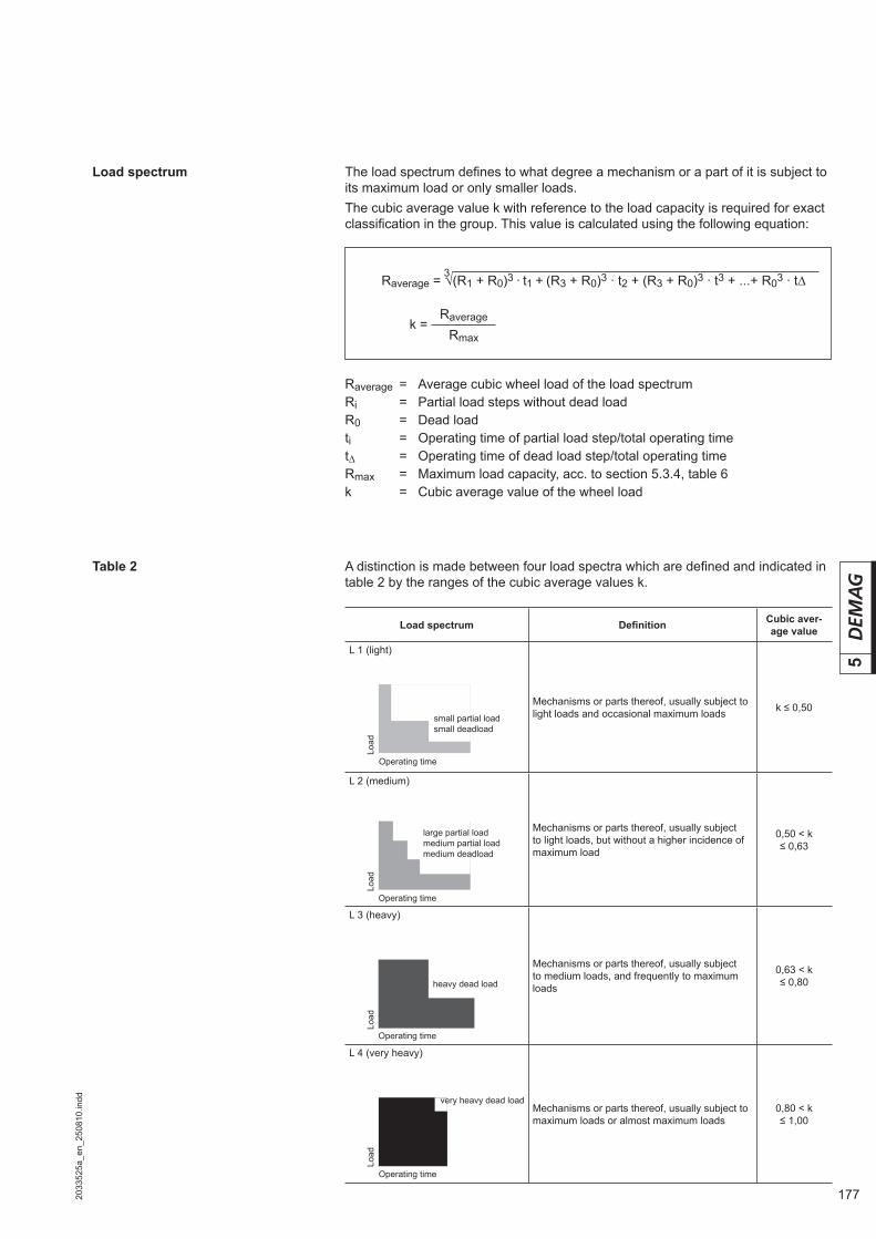
1772033
525a
_en_
2508
10.in
dd
5
Table 2
The load spectrum defi nes to what degree a mechanism or a part of it is subject to its maximum load or only smaller loads.The cubic average value k with reference to the load capacity is required for exact classifi cation in the group. This value is calculated using the following equation:
A distinction is made between four load spectra which are defi ned and indicated in table 2 by the ranges of the cubic average values k.
Load spectrum
Load
Operating time
small partial load small deadload
Load
Operating time
large partial load medium partial load medium deadload
Load
Operating time
heavy dead load
Operating time
Load
very heavy dead load
Load spectrum Defi nition Cubic aver-age value
L 1 (light)
Mechanisms or parts thereof, usually subject to light loads and occasional maximum loads k ≤ 0,50
L 2 (medium)
Mechanisms or parts thereof, usually subject to light loads, but without a higher incidence of maximum load
0,50 < k≤ 0,63
L 3 (heavy)
Mechanisms or parts thereof, usually subject to medium loads, and frequently to maximum loads
0,63 < k≤ 0,80
L 4 (very heavy)
Mechanisms or parts thereof, usually subject to maximum loads or almost maximum loads
0,80 < k≤ 1,00
Raverage = Average cubic wheel load of the load spectrumRi = Partial load steps without dead loadR0 = Dead loadti = Operating time of partial load step/total operating timet∆ = Operating time of dead load step/total operating timeRmax = Maximum load capacity, acc. to section 5.3.4, table 6k = Cubic average value of the wheel load
Raverage = √(R1 + R0)3 · t1 + (R3 + R0)3 · t2 + (R3 + R0)3 · t3 + ...+ R03 · t∆3
k = Raverage
Rmax
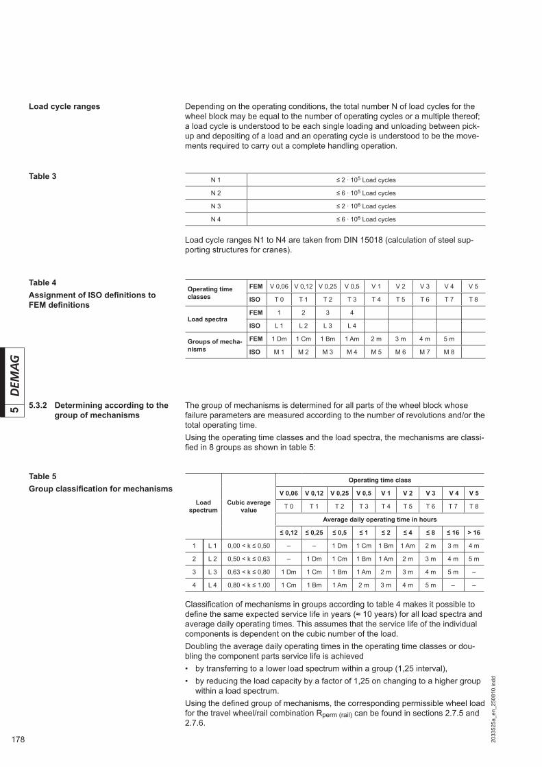
178 2033
525a
_en_
2508
10.in
dd
5 5.3.2 Determining according to the group of mechanisms
The group of mechanisms is determined for all parts of the wheel block whose failure parameters are measured according to the number of revolutions and/or the total operating time.Using the operating time classes and the load spectra, the mechanisms are classi-fi ed in 8 groups as shown in table 5:
Table 5Group classifi cation for mechanisms
Classifi cation of mechanisms in groups according to table 4 makes it possible to defi ne the same expected service life in years (≈ 10 years) for all load spectra and average daily operating times. This assumes that the service life of the individual components is dependent on the cubic number of the load.Doubling the average daily operating times in the operating time classes or dou-bling the component parts service life is achieved• by transferring to a lower load spectrum within a group (1,25 interval),• by reducing the load capacity by a factor of 1,25 on changing to a higher group
within a load spectrum.Using the defi ned group of mechanisms, the corresponding permissible wheel load for the travel wheel/rail combination Rperm (rail) can be found in sections 2.7.5 and 2.7.6.
Depending on the operating conditions, the total number N of load cycles for the wheel block may be equal to the number of operating cycles or a multiple thereof; a load cycle is understood to be each single loading and unloading between pick-up and depositing of a load and an operating cycle is understood to be the move-ments required to carry out a complete handling operation.
Table 3
Table 4Assignment of ISO defi nitions to FEM defi nitions
Load cycle ranges
Load cycle ranges N1 to N4 are taken from DIN 15018 (calculation of steel sup-porting structures for cranes).
N 1 ≤ 2 · 105 Load cycles
N 2 ≤ 6 · 105 Load cycles
N 3 ≤ 2 · 106 Load cycles
N 4 ≤ 6 · 106 Load cycles
Operating time classes
FEM V 0,06 V 0,12 V 0,25 V 0,5 V 1 V 2 V 3 V 4 V 5
ISO T 0 T 1 T 2 T 3 T 4 T 5 T 6 T 7 T 8
Load spectraFEM 1 2 3 4
ISO L 1 L 2 L 3 L 4
Groups of mecha-nisms
FEM 1 Dm 1 Cm 1 Bm 1 Am 2 m 3 m 4 m 5 m
ISO M 1 M 2 M 3 M 4 M 5 M 6 M 7 M 8
Load spectrum
Cubic average value
Operating time class
V 0,06 V 0,12 V 0,25 V 0,5 V 1 V 2 V 3 V 4 V 5
T 0 T 1 T 2 T 3 T 4 T 5 T 6 T 7 T 8
Average daily operating time in hours
≤ 0,12 ≤ 0,25 ≤ 0,5 ≤ 1 ≤ 2 ≤ 4 ≤ 8 ≤ 16 > 16
1 L 1 0,00 < k ≤ 0,50 – – 1 Dm 1 Cm 1 Bm 1 Am 2 m 3 m 4 m
2 L 2 0,50 < k ≤ 0,63 – 1 Dm 1 Cm 1 Bm 1 Am 2 m 3 m 4 m 5 m
3 L 3 0,63 < k ≤ 0,80 1 Dm 1 Cm 1 Bm 1 Am 2 m 3 m 4 m 5 m –
4 L 4 0,80 < k ≤ 1,00 1 Cm 1 Bm 1 Am 2 m 3 m 4 m 5 m – –

1792033
525a
_en_
2508
10.in
dd
5
5.3.4 Determining according to the number of service life load cycles for wheel blocks and connections to DIN 15018
The number of service life load cycles is determined for all parts of the wheel block whose failure parameters are measured according to the number of load changes.
Rperm (wheel block) = Permissible wheel load for wheel block and connectionsRmax = Maximum wheel load of the wheel block system (table 6)fa = Degree of utilization of the wheel block system (table 7)
Determining the utilization factor fa on the basis of the load spectrum and the load cycle range represents the relationship between FEM 9.511 and DIN 15018.
5.3.3 Estimating the wheel block service life
Using section 5.1.4, it is possible to determine the wheel block service life on the basis of the classifi cation according to groups of mechanisms. This does not con-sider special loads and other external infl uences.
La (DRS) = Nominal wheel block service life in years(FEM / ISO) = Full load hours according to section 5.1.4Rperm = Permissible wheel load of wheel blocks depending on the FEM/ISO
classifi cation according to sections 2.7.5 and 2.7.6.Raverage = Average cubic load of the load spectrum according to section 5.3.1dA = Number of working days per year (250 days acc. to FEM)taverage = Average daily operating time in hours according to section 5.3.1
with an example in section 5.5.3P = 3 for DRS 112 to DRS 200 = 3,33 for DRS 250 to DRS 500
Rperm (wheel block) = Rmax · fa
La (DRS) = (FEM/ISO) · ( Rperm )
P
Raverage
dA · taverage

180 2033
525a
_en_
2508
10.in
dd
5
Table 6Maximum wheel loads of the wheel block system
5.3.5 Determining the number of load cycles
A number load changes x with pick-up and depositing of a load is assumed per op-erating cycle. This results in the wheel block duration of utilization from the number of load cycles as in section 5.3.4.
N = Number of load cycles over the total service lifeLa (DRS) = Nominal wheel block service life in yearsx = Number of load changes per operating cyclencycle = Operating cycles per hourtaverage = Average daily operating time in hours according to section 5.3.1
with an example in section 5.5.3dA = Number of working days per year (250 days acc. to FEM)
DRS wheel block size Rmax in kg
112 3500
125 5000
160 7000
200 10000
250 16000
315 22000
400 30000
500 40000
Table 7Utilization factor fa
The utilization factor determines the maximum percentage utilization of the maxi-mum wheel load as a function of load spectrum L and the number of load cycles selected on the basis of the total service life.
Load spectrum N 1≤ 2 · 105
N 2≤ 6 · 105
N 3≤ 2 · 106
N 4≤ 6 · 106
L 1 1 1 0,95 0,7
L 2 1 1 0,85 0,65
L 3 1 0,9 0,7 0,55
L 4 1 0,8 0,6 0,5
N = La (DRS) · dA · ncycle · taverage · x

1812033
525a
_en_
2508
10.in
dd
5
• DRS 125 with Rmax = 5000 kg• Permissible wheel load R = 2500 kg from v = 40 m/min, FEM 3m and A55 rail,
St 60-2/E 355, 50° C ambient temperature• Permissible horizontal force for roller guide FH = 15 % of 2500 kg = 375 kN
5.4 Selection example permissible wheel load
DRS 125
Group of mecha-nisms Permissible wheel load in kg
FEM ISOTravel speed in m/min
12,5 16,0 20,0 25,0 31,5 40,0 50,0 63,0 80,0 100,0 125,0 160,0
1 Bm M 3 3970 3680 3420 3153
1 Am M 4 4210 3970 3680 3410 3150 2920 2710 2502
2 m M 5 3970 3680 3410 3150 2920 2700 2500 2320 2150 1986
3 m M 6 3680 3390 3150 2920 2700 2500 2320 2150 1980 1840 1710 1576
4 m M 7 2940 2700 2510 2330 2160 1990 1850 1710 1580 1470 1360 1258
5 m M 8 2340 2150 2000 1850 1720 1580 1470 1360 1260 1170 1080 1001
Curve radius ≥ 305
for rail material fSt travel wheel material GJS-700-2 (GGG 70)
Rail
Material DIN EN 10025Factor fSt
Linear contact Point contact
St 70-2/E 360 1 1
St 60-2/E 335 1 0,44
St 52-3/S 355 J 2 G 3 1 0,38
St 37-2/ S 235 J R 0,25 0,01
Convex travel wheel – straight rail or straight travel wheel – curved rail
A uniform temperature-dependent reduction factor fK is used for the entire wheel block.
for temperature fK
DRS wheel block size
– 20 ºCto
+ 40 ºC
to 50 ºC
to 60 ºC
to 70 ºC
to80 ºC
to90 ºC
to100 ºC
to110 ºC
to120 ºC
to130 ºC
to140 ºC
to150 ºC
DRS 112 – 200driven 1 0,85 0,8 0,75 0,6 a. A. a. A. a. A. – – – –
DRS 112 – 200non-driven 1 a. A. a. A. a. A. a. A. a. A. a. A. a. A. – – – –
DRS 250 – 500 1 1 0,92 0,90 0,88 0,86 0,84 0,82 0,80 a. A. a. A. a. A.
A reduction factor fST is introduced for linear or point contact depending on the material of the rail.
a. A. = On request

182 2033
525a
_en_
2508
10.in
dd
5
Permissible wheel load (rail) = perm R (point) x fSt x fRs
Rperm (rail) in kg = 2500 kg x 0,44 x 1 = 1100 kgPermissible wheel load (temperature) in kg = Rperm (point) x fK
Rperm (temperature) = 2500 kg x 0,85 = 2125 kg
Rmax perm = Minimum [Rperm (rail) : Rperm (temperature)] = Minimum [1100 kg : 2125 kg] = 1100 kg
Rail shape
Factor fRs
A railDIN 536 Part 1 Rail shape Rail curve radius in mm
41409244.eps
A 045A 55A 065A 075A 100A 120A 150
400400400500500600800
Curve radius r2 DRS wheel block size
in mm 112 125 160 200 250 315 400 500
> 140 - - - - - - -
≥ 140 0,68 0,53 0,42 0,37 0,29 0,26 0,24 0,22
≥ 160 0,76 0,59 0,47 0,4 0,33 0,30 0,28 0,26
≥ 180 0,84 0,66 0,52 0,46 0,37 0,34 0,31 0,29
≥ 210 0,95 0,74 0,59 0,53 0,42 0,39 0,36 0,34
≥ 225 0,79 0,63 0,56 0,45 0,42 0,39 0,37
≥ 300 0,99 0,80 0,71 0,58 0,54 0,52 0,49
≥ 305 0,81 0,72 0,59 0,55 0,52 0,5
≥ 400 0,90 0,73 0,70 0,67 0,64
≥ 500 0,88 0,84 0,81 0,78
≥ 600 0,97 0,95 0,92
≥ 625 0,98 0,95
≥ 645 1 0,98
≥ 665
≥ 790
≥ 1005
≥ 1260
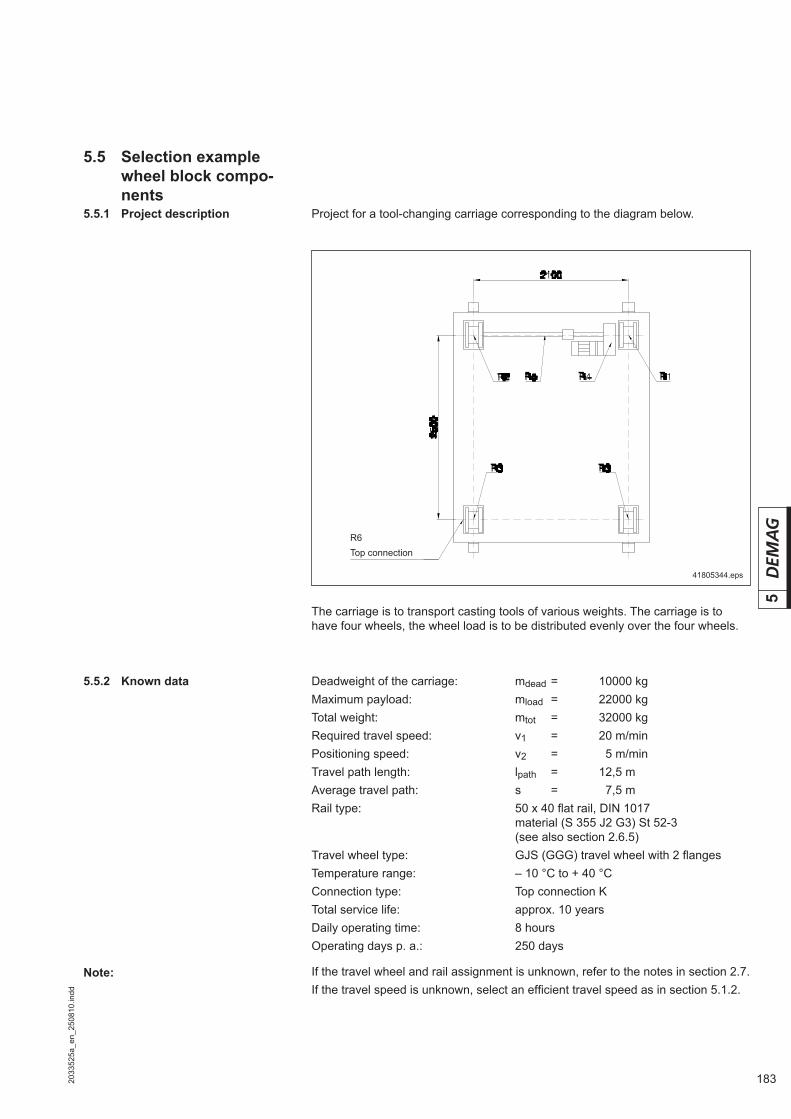
1832033
525a
_en_
2508
10.in
dd
5
Project for a tool-changing carriage corresponding to the diagram below.
The carriage is to transport casting tools of various weights. The carriage is to have four wheels, the wheel load is to be distributed evenly over the four wheels.
41805344.eps
Deadweight of the carriage: mdead = 10000 kgMaximum payload: mload = 22000 kgTotal weight: mtot = 32000 kgRequired travel speed: v1 = 20 m/minPositioning speed: v2 = 05 m/minTravel path length: lpath = 12,5 mAverage travel path: s = 7,5 mRail type: 50 x 40 fl at rail, DIN 1017 material (S 355 J2 G3) St 52-3 (see also section 2.6.5)Travel wheel type: GJS (GGG) travel wheel with 2 fl angesTemperature range: – 10 °C to + 40 °CConnection type: Top connection KTotal service life: approx. 10 yearsDaily operating time: 8 hoursOperating days p. a.: 250 days
If the travel wheel and rail assignment is unknown, refer to the notes in section 2.7.If the travel speed is unknown, select an effi cient travel speed as in section 5.1.2.
Note:
5.5 Selection example wheel block compo-nents
5.5.1 Project description
5.5.2 Known data
R6Top connection
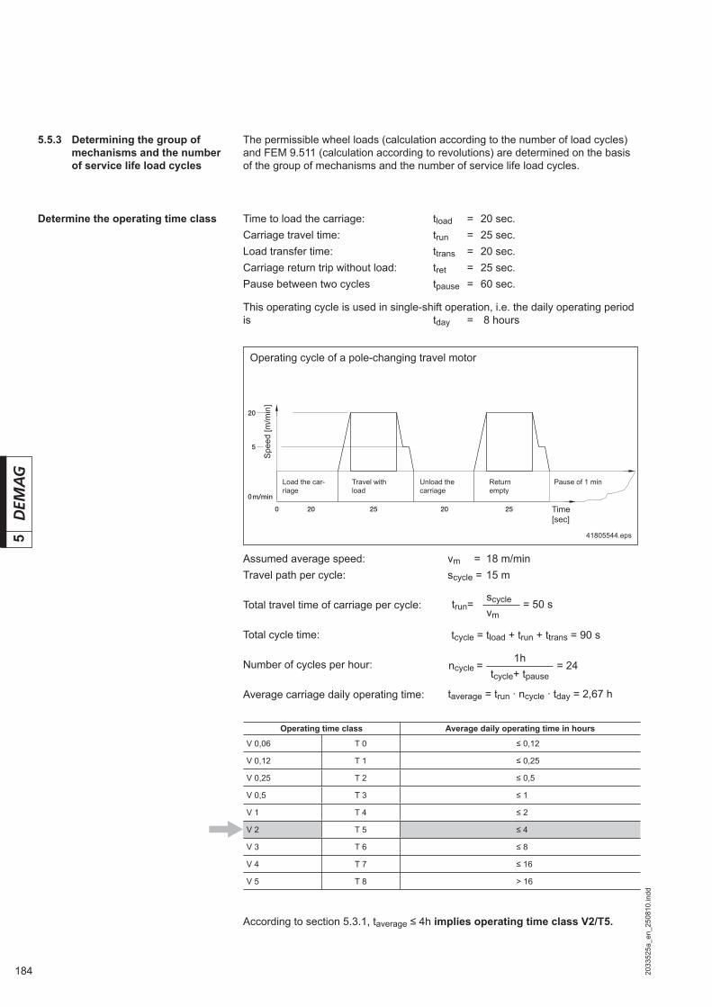
184 2033
525a
_en_
2508
10.in
dd
5
Assumed average speed: vm = 18 m/minTravel path per cycle: scycle = 15 m
Total travel time of carriage per cycle:
Total cycle time:
Number of cycles per hour:
Average carriage daily operating time:
Determine the operating time class
The permissible wheel loads (calculation according to the number of load cycles) and FEM 9.511 (calculation according to revolutions) are determined on the basis of the group of mechanisms and the number of service life load cycles.
Time to load the carriage: tload = 20 sec.Carriage travel time: trun = 25 sec.Load transfer time: ttrans = 20 sec.Carriage return trip without load: tret = 25 sec.Pause between two cycles tpause = 60 sec.
This operating cycle is used in single-shift operation, i.e. the daily operating period is tday = 8 hours
20
0 20 25 20 25
0m/min
05
41805544.eps
Operating cycle of a pole-changing travel motor
Time [sec]
Spe
ed [m
/min
]
According to section 5.3.1, taverage ≤ 4h implies operating time class V2/T5.
Operating time class Average daily operating time in hours
V 0,06 T 0 ≤ 0,12
V 0,12 T 1 ≤ 0,25
V 0,25 T 2 ≤ 0,5
V 0,5 T 3 ≤ 1
V 1 T 4 ≤ 2
V 2 T 5 ≤ 4
V 3 T 6 ≤ 8
V 4 T 7 ≤ 16
V 5 T 8 > 16
5.5.3 Determining the group of mechanisms and the number of service life load cycles
taverage = trun · ncycle · tday = 2,67 h
tcycle = tload + trun + ttrans = 90 s
trun= scycle = 50 svm
ncycle = 1h
= 24tcycle+ tpause
Load the car-riage
Travel with load
Unload the carriage
Return empty
Pause of 1 min

1852033
525a
_en_
2508
10.in
dd
5
Determine the load spectrum
The wheel loads for operation of the carriage are to be distributed as follows:
The load spectrum indicates to what degree a mechanism is subject to its maxi-mum load or smaller loads.The cubic average value k with reference to the load capacity is required for exact classifi cation in the group. The ratio of the average cubic load, from the load spec-trum, to the maximum load capacity must be calculated.
The maximum wheel load for this application is 8000 kg. A DRS 250 is initially selected from the load capacity tables with a max. load capacity Rmax = 10000 kg (section 5.3.4, table 7).
The cubic average amounts to:
The average wheel load amounts to:
Wheel block selection
41805444.eps
8000 kg
7200 kg
5800 kg
2500 kg
50%20%28%
100%
2%
[%]
Load spectrum of a travel wheel
Wheel load due to dead weight
Load [kg]
Average wheel load
Time
Wheel loads in kg Frequency in %
8000 28
7200 20
2500 50
5800 02
k = Raverage =
6124 kg= 0,612
Rmax 10000 kg
Raverage = √ (80003 · 0,28) + (72003 · 0,2) + (58003 · 0,02) + (25003 · 0,5) kg3
Raverage = 6124 kg

186 2033
525a
_en_
2508
10.in
dd
5
Rail
Material Factor fSt
St 70-2/E 360 1
St 60-2/E 335 1
St 52-3/S 355 J 2 G 3 1
St 37-2/ S 235 J R 0,25
5.5.4 Check the wheel block selection
Determine the permissible wheel load for the rail/travel wheel combination
From section 2.7.5 with• Speed v1 = 20 m/min• Group of mechanisms 2 m• Rail width 50 mm• Straight travel wheel on fl at rail.
According to section 2.7.5 a maximum permissible wheel load from linear contact is given Rperm (rail) = Rperm (line contact) x fSt
= 8320 kg x 1,0 = 8320 kgAccording to section 1.11 a maximum permissible wheel load from temperature is given Rperm (temperature) = Rperm (line contact) x fK = 8320 kg x 1,0 = 8320 kgThis results in a maximum wheel load Rmax perm = Minimum [ Rperm (rail) : Rperm (temperature)] = Minimum [ 8320 kg : 8320 kg ] = 8320 kg Rmax ≤ Rmax perm
8000 kg < 8320 kg.
Determine the group of mechanisms According to FEM 9.511, classifi cation into groups of mechanisms results in a service life of approx. 10 years.
Load spectrum L1 and operating time class L1 result in Group of mechanisms 2 m.
Group of mecha-nisms Useful rail
head width in mm
Permissible wheel load in kg
FEM ISOTravel speed in m/min
12,5 16 20 25 31 40 50 63 80 100 125 160
2 m M 5
30 05750 05340 4990 04670 04360 04050 03790 03540 03290 03080 02880 02670
35 06710 06230 5830 05450 05080 04730 04420 04130 03840 03590 03360 03120
40 07670 07120 6660 06230 05810 05410 05060 04720 04390 04110 03840 03570
45 08630 08010 7490 07010 06540 06080 05690 05310 04940 04620 04325 04010
50 09580 08900 8320 07780 07260 06760 06320 05900 05490 05130 04800 04460
³ 55 10000 09790 9160 08560 07990 07440 06950 06490 06040 05650 05280 04900
Load spectrum
Cubic average value
Operating time class
V 0,06
V 0,12
V 0,25 V 0,5 V 1 V 2 V 3 V 4 V 5
T 0 T 1 T 2 T 3 T 4 T 5 T 6 T 7 T 8
Average daily operating time in hours
≤ 0,12 ≤ 0,25 ≤ 0,5 ≤ 1 ≤ 2 ≤ 4 ≤ 8 ≤ 16 > 16
1 L 1 0,00 < k ≤ 0,50 – – 1 Dm 1 Cm 1 Bm 1 Am 2 m 3 m 4 m
2 L 2 0,50 < k ≤ 0,63 – 1 Dm 1 Cm 1 Bm 1 Am 2 m 3 m 4 m 5 m
3 L 3 0,63 < k ≤ 0,80 1 Dm 1 Cm 1 Bm 1 Am 2 m 3 m 4 m 5 m –
4 L 4 0,80 < k ≤ 1,00 1 Cm 1 Bm 1 Am 2 m 3 m 4 m 5 m – –

1872033
525a
_en_
2508
10.in
dd
55.5.5 Determining the number of
service life load cycles
A theoretical load changing operation with load pick-up and load depositing is car-ried out for each operating cycle. For practical purposes (e.g. for aligning the tool on the carriage and depositing it at an intermediate position) x = 3 load changing operations per operating cycle is assumed.
N 1 ≤ 2 · 105 load cycles
N 2 ≤ 6 · 105 load cycles
N 3 ≤ 2 · 106 load cycles
Wheel block service life On the basis of 1600 hours of full load service life in group of mechanisms 2 m (see section 5.1.4) acc. to section 5.3.3.
250 working days are assumed per year according to FEM:
= 6966 h
= 10,5 years
The next larger wheel block must be selected if a higher service life is required.
Determine the number of service life load cycles
N = 504.630 load cycles ≤ 600.000 load cycles≡ N2.
= 10,5 years · 250 days / year · 24 · 2,67 · 3
L a(DRS) =6966
250 · 2,67
= 504.630 cycles
N = La (DRS) · dA · ncycle · taverage · x
L a(DRS) = FEM/ISO ·
L a(DRS) = 1600 ·
L a(DRS) = FEM/ISO ·
( Rmax )3
Raverage
dA · taverage
( Rmax )3
Raverage
( 10000 )3
6124

188 2033
525a
_en_
2508
10.in
dd
5
5.5.7 Buffer selection DPZ cellular foam buffers are the standard buffers for the DRS wheel block sys-tem. From section 4.4.2 this implies for:
Travel speed of 20 m/minCross travel (no speed reduction measures)Maximum mass to be buffered 32000 kg distributed on 2 buffers per side:without counterbuffer: Buffer size DPZ 160, 16000 kgwith counterbuffer: Buffer size DPZ 130, 08000 kg
DPZ cellular plastic buffer
With counterbuffer:The maximum mass which can be buffered is doubled when a counterbuffer of the same size is used.The values given in the table are the maximum masses which can be buffered. It must be considered that the minimum mass to be buffered must not be less than 20 % of the table value (40 % when a counterbuffer is used) due to the acceleration which occurs in the event of a buffer impact.
Cellular foam buffer Travel speed in m/min
Limit switch k=70% to 14,3 to 17,9 to 22,9 to 28,6 to 35,7 to 45,0 to 57,1 to 71,4 to 90,0 to 114,3 to 142,9 to 178,6 to 228,6
Long travel k=85% to 11,8 to 14,7 to 18,8 to 23,5 to 29,4 to 37,1 to 47,1 to 58,8 to 74,1 to 94,1 to 117,6 to 147,1 to 188,2
Cross travel k=100% to 10,0 to 12,5 to 16,0 to 20,0 to 25,0 to 31,5 to 40,0 to 50,0 to 63,0 to 80,0 to 100,0 to 125,0 to 160,0
DRS wheel block size Buffer max. mass which can be buffered in kg without counterbuffer
112 – 400 DPZ 70 6400 4170 2600 1710 1120 730 480
112 – 400 DPZ 100 22230 14500 9080 5980 2960 2610 1710 1160
160 – 400 DPZ 130 48480 31670 19660 12900 8500 5560 3610 2460
200 – 400 DPZ 160 87300 66760 34720 22740 14960 9760 6330 7270
400 DPZ 210 130140 84730 67730 34560 22760 14780 9660 6500 7360
5.5.6 Determining the permissible wheel load
According to section 5.3.5, table 7, this results in a maximum utilization factor of fa = 1,0.
The maximum permissible wheel load for the DRS 200 is 10000 kg according to section 5.3.4 table 6. Accordingly, the maximum permissible load amounts to
Rperm (wheel block) = 10000 kg · 1,0 = 10000 kg.
With a maximum actual wheel load of Rmax exist = 8320 kg,the connection arrangement of the DRS 200 is adequately dimensioned.
Load spectrum N 1≤ 2 · 105
N 2≤ 6 · 105
N 3≤ 2 · 106
N 4≤ 6 · 106
L 1 1 1 0,95 0,7
L 2 1 1 0,85 0,65
L 3 1 0,9 0,7 0,55
L 4 1 0,8 0,6 0,5

1892033
525a
_en_
2508
10.in
dd
5
5.5.8 Guide arrangement The carriage is to be fi tted with travel wheels with fl anges. A travel wheel tread of b = 65 mm is required for a 55 x 30 fl at rail.
If an exact guide arrangement is required, we recommend the carriage be fi tted with wheel blocks featuring guide fl anges or a roller guide arrangement (rail head width +2 mm) on one side.
Distance s on each side minimum 1 mm, maximum 5 mm in tolerance class 2 to VDI 3576
1) Tolerance class 2 to VDI 35762) DRS 112 – 200 available in steps of 1 mm3) Hardened travel wheels (treads and fl anges), for DRS 112 – 200, fl anges without wear indicator
GJS-700-2 (GGG 70) spheroidal graphite cast iron travel wheel
41617944.eps
sk
b12b1
ks
A D
Travel wheel dia.
Travel wheel width
Travel wheel tread b1 2) Distance s Rail width
Standard travel wheel type
per side
1)
to to 3) A D min. max. k
112 80 60 62 47, 60 47 1 5 40, 45, 50, 55, 60
125 80 60 62 47, 60 47, 60 1 5 40, 45, 50, 55, 60
160 89 65 67 47, 60, 65 47, 65 1 5 40, 45, 50, 55, 60, 65
200 101 67 75 65, (75 3)) 65 1 5 50, 55, 60, 70
250 110 77 80 52, 65, 75 65, 75 1 5 50, 55, 60, 70, 75
315 130 90 96 65, 80, 90 80, 90 1 5 60, 70 75, 80, 90
400 155 110 - 80, 90, 110 80, 110 1 5 65, 70, 75, 80, 90, 100
500 170 110 - 90, 110 90, 110 1 5 70, 75, 80, 90, 100

190 2033
525a
_en_
2508
10.in
dd
5
5.5.9 Select the drive variant Make a preliminary selection using the quick selection table for gearbox/motor combinations (see geared travel motors catalogue 203 013 44, Volume 3, sec-tion 1.5).
1) DRS 200 - AME 30 TD - ZBF 63 A 8/22) DRS 200 - AME 30 TD - ZBF 71 (80) A 8/2
v 1,6/ 2/ 2,5/ 3,15/ 4/ 5/ 6,3/ 8/ 10/ 2,5/ 3,15/ 4/ 5/ 6,3/ 8/ 10/ 12,5/ 16/[m/min.] 10 12,5 16 20 25 31,5 40 50 63 10 12,5 16 20 25 31,5 40 50 63,0
GetriebeGearbox
Réducteur
A . . 30 i 156 109 86,4 71,9 55,7 45,5 36,1 29,2
1)
1352)
156
109 86,4 71,9 55,7 45,5 36,1 29,2
A . . 40 i 184 150 115 91,1 73,8 55,7 44,3 36,1 28,1 184 150 115 91,1 73,8 55,7 44,3 36,1 28,1
A . . 50 i 142 87,4 56,4 46,7 142 87,0 56,4 46,7
Masse m pro Antrieb kg / Mass per drive in kg / Masse par mécanisme en kg
100
1400 26 14 4 23 11 1 2 3
2800
4200
5600 5
7000
8400
9800 6
11200 12 5
12600
14000
15400 8 10 20 24 13
16800 7 9 19
18200 22
19600 16 20 15
21000 21
22400
23800
25200 17
26600 22 25
28000
29400 21
30800 28 30 32 18 20
32200 29 19
33600
35000
36400
37800 40 34 36 27 39 31 33
39200 35
40600
38 37
Gearbox/motor combination 2932000
5,0/20,0

1912033
525a
_en_
2508
10.in
dd
5Selected: Gearbox AME 40 T with i = 91Section 2.5 indicates that this design is possible.
Drive combination selected:
Check the gearbox/motor combination as in section 2.5 ZI central drive unit, inside arrangement
Gearbox/motor combination: 29
Combination code Gearbox Motor CDF % Output kW Speed rpm
27
AME 40 TD
ZBF 90 B 8/2
40
0,20/0,80 690/2765
29 ZBF 100 A 8/2 0,29/1,20 685/2760
31 ZBF 112 A 8/2 0,46/1,90 705/2855
Motor frame size
DRS wheel block size112 125 160 200 250 315 400
A offset gearbox size
10 20 20 30 30 40 40 50 50 60 60 70 70 80
ZBF ZBA
63A, 71A 63A/B, 71A/B ● ● ● ● ● ● ●80A 80A/B, 90A ● ● ● ● ● ● ● ● ● ● ● ●90B, 100A 90B, 100A/B ● ● ● ● ● ● ● ● ● ● ●112A, 132A/B 112A, 132A/B/C ● ● ● ● ● ● ●
160A/B,180A ● ● ● ●180B,200A ●225A/B ●
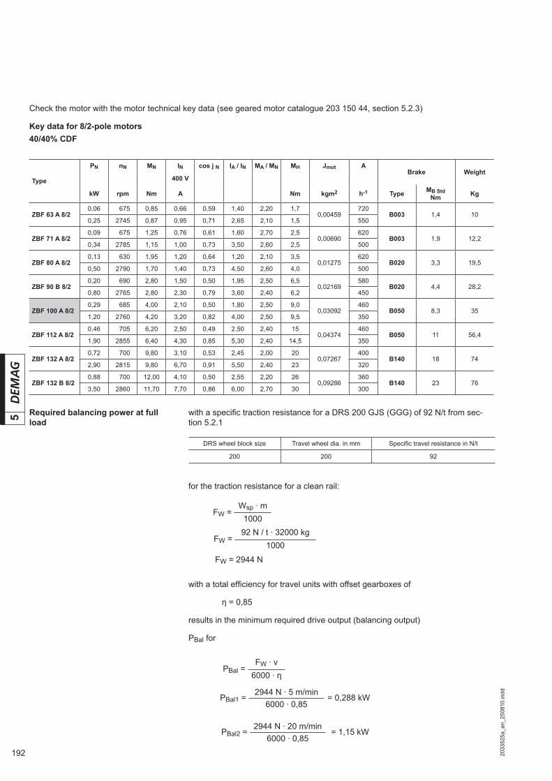
192 2033
525a
_en_
2508
10.in
dd
5
for the traction resistance for a clean rail:
with a total effi ciency for travel units with offset gearboxes of
η = 0,85
results in the minimum required drive output (balancing output)
PBal for
Check the motor with the motor technical key data (see geared motor catalogue 203 150 44, section 5.2.3)
Key data for 8/2-pole motors40/40% CDF
with a specifi c traction resistance for a DRS 200 GJS (GGG) of 92 N/t from sec-tion 5.2.1
Required balancing power at full load
DRS wheel block size Travel wheel dia. in mm Specifi c travel resistance in N/t
200 200 92
Type
PN nN MN IN cos j N IA / IN MA / MN MH Jmot ABrake Weight
400 V
kW rpm Nm A Nm kgm2 h-1 Type MB StdNm Kg
ZBF 63 A 8/2 0,06 0675 0,85 0,66 0,59 1,40 2,20 1,7
0,00459720
B003 1,4 100,25 2745 0,87 0,95 0,71 2,65 2,10 1,5 550
ZBF 71 A 8/20,09 0675 1,25 0,76 0,61 1,60 2,70 2,5
0,00690620
B003 1,9 12,20,34 2785 1,15 1,00 0,73 3,50 2,60 2,5 500
ZBF 80 A 8/2 0,13 0630 1,95 1,20 0,64 1,20 2,10 3,5
0,01275620
B020 3,3 19,50,50 2790 1,70 1,40 0,73 4,50 2,60 4,0 500
ZBF 90 B 8/2 0,20 0690 2,80 1,50 0,50 1,95 2,50 6,5
0,02169580
B020 4,4 28,20,80 2765 2,80 2,30 0,79 3,60 2,40 6,2 450
ZBF 100 A 8/20,29 0685 4,00 2,10 0,50 1,80 2,50 9,0
0,03092460
B050 8,3 351,20 2760 4,20 3,20 0,82 4,00 2,50 9,5 350
ZBF 112 A 8/2 0,46 0705 6,20 2,50 0,49 2,50 2,40 15
0,04374460
B050 11 56,41,90 2855 6,40 4,30 0,85 5,30 2,40 14,5 350
ZBF 132 A 8/20,72 0700 9,80 3,10 0,53 2,45 2,00 20
0,07267400
B140 18 742,90 2815 9,80 6,70 0,91 5,50 2,40 23 320
ZBF 132 B 8/2 0,88 0700 12,00 4,10 0,50 2,55 2,20 26
0,09286360
B140 23 763,50 2860 11,70 7,70 0,86 6,00 2,70 30 300
FW = Wsp · m
1000
FW = 92 N / t · 32000 kg
1000
PBal = FW · v
6000 · η
FW = 2944 N
PBal1 = 2944 N · 5 m/min
= 0,288 kW6000 · 0,85
PBal2 = 2944 N · 20 m/min
= 1,15 kW6000 · 0,85
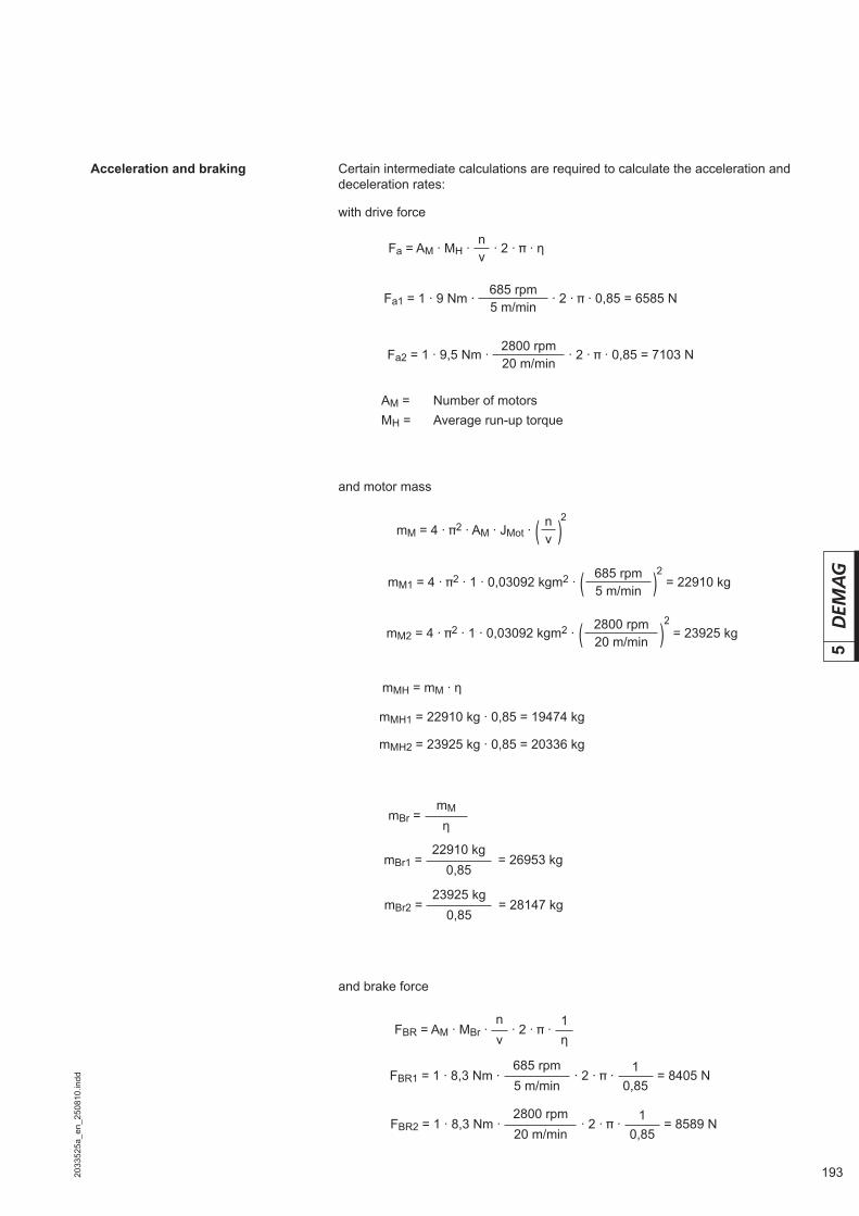
1932033
525a
_en_
2508
10.in
dd
5
Certain intermediate calculations are required to calculate the acceleration and deceleration rates:
with drive force
Acceleration and braking
and brake force
and motor mass
AM = Number of motorsMH = Average run-up torque
Fa = AM · MH · n
· 2 · · ηv
Fa1 = 1 · 9 Nm · 685 rpm
· 2 · · 0,85 = 6585 N5 m/min
Fa2 = 1 · 9,5 Nm · 2800 rpm
· 2 · · 0,85 = 7103 N20 m/min
mM = 4 · 2 · AM · JMot · ( n )v
2
mM1 = 4 · 2 · 1 · 0,03092 kgm2 · ( 685 rpm ) = 22910 kg5 m/min
2
mM2 = 4 · 2 · 1 · 0,03092 kgm2 · ( 2800 rpm ) = 23925 kg20 m/min
2
mMH = mM · η
mMH1 = 22910 kg · 0,85 = 19474 kg
mMH2 = 23925 kg · 0,85 = 20336 kg
mBr = mM
η
mBr1 = 22910 kg
= 26953 kg0,85
mBr2 = 23925 kg
= 28147 kg0,85
FBR = AM · MBr · n
· 2 · ·1
v η
FBR1 = 1 · 8,3 Nm · 685 rpm
· 2 · ·1
= 8405 N5 m/min 0,85
FBR2 = 1 · 8,3 Nm · 2800 rpm
· 2 · ·1
= 8589 N20 m/min 0,85
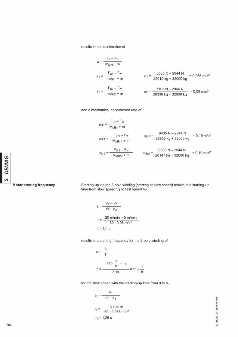
194 2033
525a
_en_
2508
10.in
dd
5
Motor starting frequency
results in an acceleration of
Starting-up via the 8-pole winding (starting at slow speed) results in a starting-up time from slow speed V1 to fast speed V2
results in a starting frequency for the 2-pole winding of
for the slow speed with the starting-up time from 0 to V1
and a mechanical deceleration rate of
a = Fa – Fw
mMH + m
a1 = Fa1 – Fw
mMH1 + m
a2 = Fa2 – Fw
mMH2 + m
aBr = FBr – Fw
MMBr + m
aBr1 = FBr1 – Fw
MMBr1 + m
aBr2 = FBr2 – Fw
MMBr2 + m
a1 = 6585 N – 2944 N
= 0,066 m/s222910 kg + 32000 kg
a2 = 7103 N – 2944 N
= 0,08 m/s220336 kg + 32000 kg
aBr1 = 8405 N – 2944 N
= 0,19 m/s226953 kg + 32000 kg
aBr2 = 8589 N – 2944 N
= 0,19 m/s228147 kg + 32000 kg
t = V2 – V1
60 · a2
t = 20 m/min – 5 m/min
60 · 0,08 m/s2
t = 3,1 s
c = At
c = = 1131
3,1s h
350 1
· 1 sh
t1 = V1
60 · a1
t1 = 5 m/min
60 · 0,066 m/s2
t1 = 1,26 s
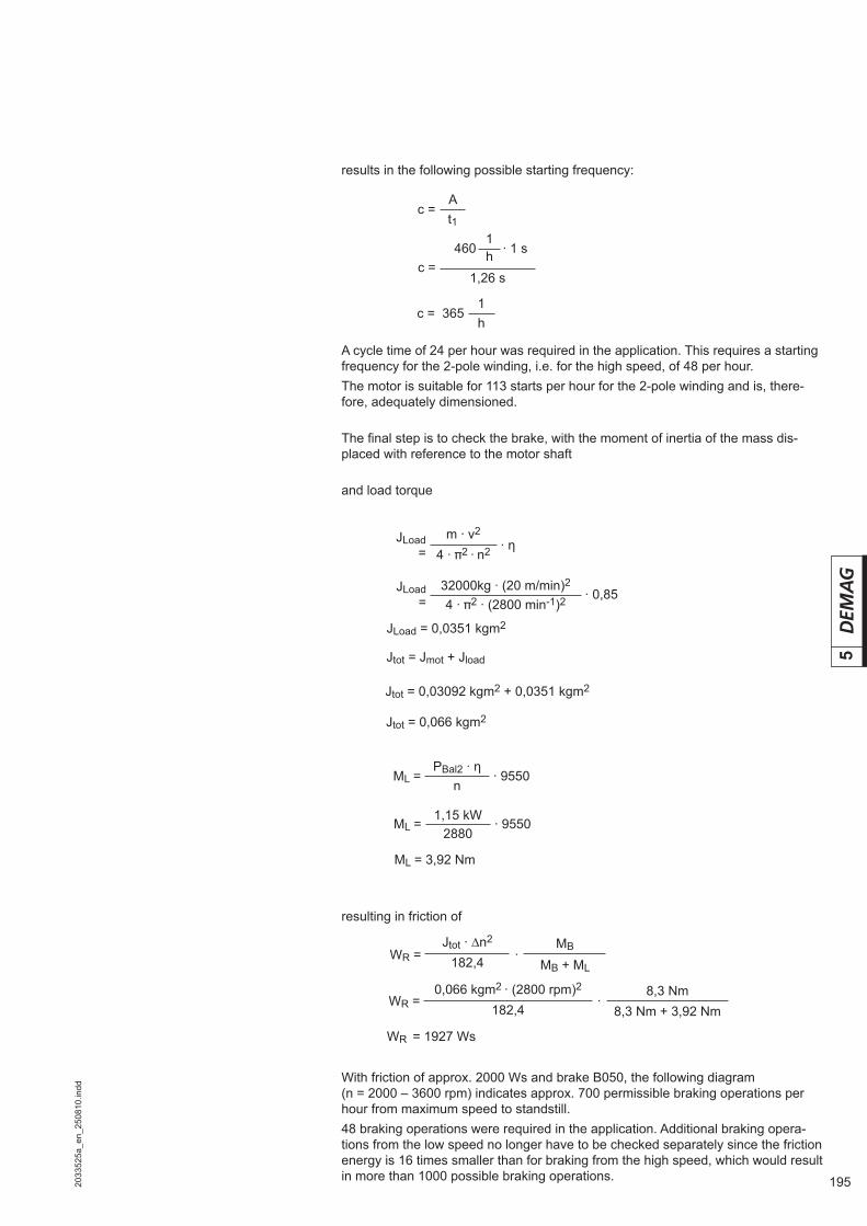
1952033
525a
_en_
2508
10.in
dd
5
results in the following possible starting frequency:
With friction of approx. 2000 Ws and brake B050, the following diagram (n = 2000 – 3600 rpm) indicates approx. 700 permissible braking operations per hour from maximum speed to standstill.48 braking operations were required in the application. Additional braking opera-tions from the low speed no longer have to be checked separately since the friction energy is 16 times smaller than for braking from the high speed, which would result in more than 1000 possible braking operations.
resulting in friction of
A cycle time of 24 per hour was required in the application. This requires a starting frequency for the 2-pole winding, i.e. for the high speed, of 48 per hour.The motor is suitable for 113 starts per hour for the 2-pole winding and is, there-fore, adequately dimensioned.
The fi nal step is to check the brake, with the moment of inertia of the mass dis-placed with reference to the motor shaft
and load torque
c = At1
c = 1,26 s
460 1
· 1 sh
c = 3651h
JLoad =
m · v2· η
4 · 2 · n2
JLoad =
32000kg · (20 m/min)2· 0,85
4 · 2 · (2800 min-1)2
JLoad = 0,0351 kgm2
Jtot = Jmot + Jload
Jtot = 0,03092 kgm2 + 0,0351 kgm2
Jtot = 0,066 kgm2
ML = PBal2 · η
· 9550n
ML = 1,15 kW
· 95502880
ML = 3,92 Nm
WR = Jtot · ∆n2
· MB
182,4 MB + ML
WR = 1927 Ws
WR = 0,066 kgm2 · (2800 rpm)2
· 8,3 Nm
182,4 8,3 Nm + 3,92 Nm

196 2033
525a
_en_
2508
10.in
dd
5
100000
10000
1000
100
101 10 100 1000 10000
n <= 3600 1/min
100
100
100000
10000
1000
101 10 1000 10000
n <= 2000 1/min
42505844.epsBraking operation per hour
Permissible friction per braking operation depending on starting frequency per hour
Per
mis
sibl
e fri
ctio
n W
R p
er b
raki
ng o
pera
tion
in J
Braking operation per hour
Permissible friction per braking operation depending on starting frequency per hour
Per
mis
sibl
e fri
ctio
n W
R p
er b
raki
ng o
pera
tion
in J
42505744.eps
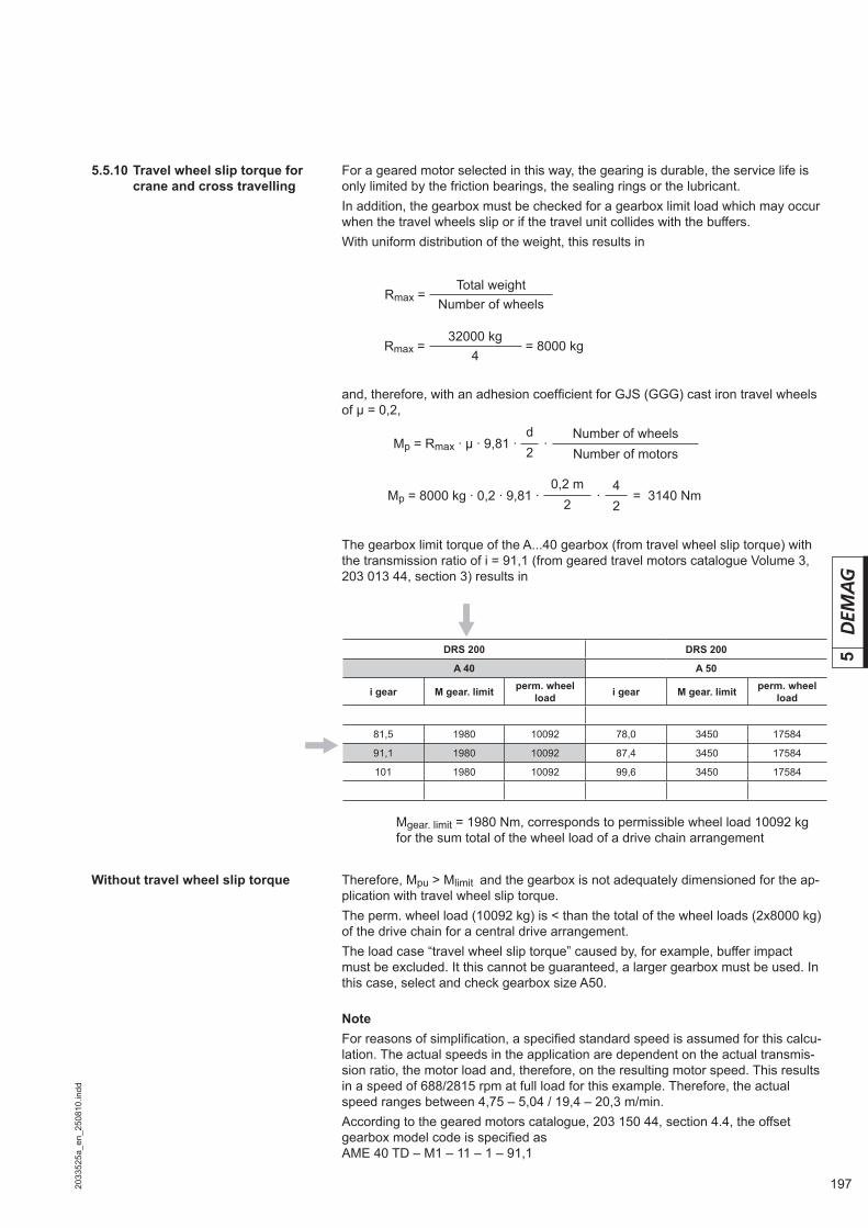
1972033
525a
_en_
2508
10.in
dd
5DRS 200 DRS 200
A 40 A 50
i gear M gear. limit perm. wheel load i gear M gear. limit perm. wheel
load
81,5 1980 10092 78,0 3450 17584
91,1 1980 10092 87,4 3450 17584
101 1980 10092 99,6 3450 17584
and, therefore, with an adhesion coeffi cient for GJS (GGG) cast iron travel wheels of μ = 0,2,
For a geared motor selected in this way, the gearing is durable, the service life is only limited by the friction bearings, the sealing rings or the lubricant.In addition, the gearbox must be checked for a gearbox limit load which may occur when the travel wheels slip or if the travel unit collides with the buffers.With uniform distribution of the weight, this results in
5.5.10 Travel wheel slip torque for crane and cross travelling
NoteFor reasons of simplifi cation, a specifi ed standard speed is assumed for this calcu-lation. The actual speeds in the application are dependent on the actual transmis-sion ratio, the motor load and, therefore, on the resulting motor speed. This results in a speed of 688/2815 rpm at full load for this example. Therefore, the actual speed ranges between 4,75 – 5,04 / 19,4 – 20,3 m/min.According to the geared motors catalogue, 203 150 44, section 4.4, the offset gearbox model code is specifi ed as AME 40 TD – M1 – 11 – 1 – 91,1
Without travel wheel slip torque
Rmax = Total weight
Number of wheels
Rmax = 32000 kg
= 8000 kg4
Mp = Rmax · μ · 9,81 ·d
· Number of wheels
2 Number of motors
Mp = 8000 kg · 0,2 · 9,81 ·0,2 m
· 4
= 3140 Nm2 2
The gearbox limit torque of the A...40 gearbox (from travel wheel slip torque) with the transmission ratio of i = 91,1 (from geared travel motors catalogue Volume 3, 203 013 44, section 3) results in
Mgear. limit = 1980 Nm, corresponds to permissible wheel load 10092 kg for the sum total of the wheel load of a drive chain arrangement
Therefore, Mpu > Mlimit and the gearbox is not adequately dimensioned for the ap-plication with travel wheel slip torque.The perm. wheel load (10092 kg) is < than the total of the wheel loads (2x8000 kg) of the drive chain for a central drive arrangement.The load case “travel wheel slip torque” caused by, for example, buffer impact must be excluded. It this cannot be guaranteed, a larger gearbox must be used. In this case, select and check gearbox size A50.

198 2033
525a
_en_
2508
10.in
dd
5
5.5.14 Select the components Qty. Designation Item
1 DRS 200 – A50 – A65 – K – X – A40 R1
1 DRS 200 – MA50 – A65 – K – X – X R2
2 DRS 200 – NA – A65 – K – X – X R3
1 Geared travel motor AME 40TD – M1 – 11 – 1 – 91,1 / ZBF 100 A 8/2 B050 R4
1 Torque bracket MA 200-1 (part no. 753 190 44) R4
1 Central shaft set (part no. 860 303 46). R5
4 Top connection set (part no. 752 520 44). R6
5.5.11 Select the drive shaft
5.5.13 Special measures
5.5.12 Determine the type key
For the track gauge of 2100 mm and the drive selected in accordance with section 3.11.2, the following drive shaft set should be selected:
Central shaft set Part no.: 860 313 46
The intermediate shaft is suitable for a maximum track gauge of 2240 mm and can be shortened appropriately to the actual track gauge dimension.
The following type key is selected for the four wheel blocks according to sec-tion 2.7: 1 x DRS 200 – A 50 – A 65 – K – X – A40 1 x DRS 200 – MA 50 – A 65 – K – X – X 2 x DRS 200 – NA – A 65 – K – X – X
The tool-changing carriage is operated indoors at normal ambient temperatures and under clean operating conditions. Therefore, special measures are not re-quired.

1992033
528a
_en_
2508
10.in
dd
6
6 Appendix
6.1 Notes on ordering Kindly read the following remarks concerning orders to ensure that your orders are processed smoothly and rapidly.If you have any questions, please contact your drive supplier or our technical de-partment.
Please refer to our quote/calculation with project no. and date. Please mark any changes or additions clearly.
6.1.1 Ordering on the basis of a quote or drive calculation
Please use the fax on the following pages to ensure that your order is complete and to avoid the need for any further clarifi cation.
6.1.2 Ordering drives selected by you or your customers
To clearly identify the original delivery, we require the serial/motor no. stamped on the rating plate. Further technical details are not required.
6.1.3 Replacement drive

200 2033
528a
_en_
2508
10.in
dd
6
6.2 Enquiry/order
Connection type Top connection Side connection Pin connection End connection
Fax serviceYour hotline for wheel block systemsFax no. see section 6.4
Enquiry/orderDemag DRS wheel block systemPlease send the quote to
Company
P.O. Box/street
Post code/town, city
Contact
Telephone/extension
Telefax
Demag Cranes & Components
Travel wheel type
Flange on both sides
With guide rollers, no fl anges
With larger diameter, no fl anges
Hydropur, no fl anges
Special wheels
Polya-mide, no fl anges
Flange on one side
Number of wheel blocks
Travel rail, type/dimensions
Additional information
Deadweight of superstructure kg
Useful load kg
Travel path length mm
Required stopping accuracy mm
Please send a quote Please call me as I have further questions
Operation under cover outdoors
Mains voltage V Hz
Inverter operation Yes No
No drive Qty.Qty. With individual drive unit Qty. Wheel block pairs with central
drive unit
Motor, type Max. wheel load in kg
Travel speed in m/min

2012033
528a
_en_
2508
10.in
dd
6
6.3 Project data sheet
Enquiry data:
From company:
Mr./Ms.:
Department:
Address:
Date:
Telephone:
Telefax:
Required delivery date:
Fax no. (see section 6.4)
Project data sheetDemag DRS wheel block system
Mass to be displaced: of which deadweight:
Travel speed: Positioning speed:
Acceleration: Deceleration:
CDF: Starting frequency:
Operating hours per day:
Travel path: Travel wheel diameter:
Number of wheels: of which driven:
Number of motors: Stopping accuracy:
Travel path gradient: Wind force:
Rail/rail head width:
Travel wheel material:
Travel wheel type(only for cast iron wheels):
Connection variants:
Drive variants:
Accessories:
Environment:
Geared motor data:
Cast iron Polyamide Hydropur
Flange on both sides Tread width:
Flange on one side Running surface width:
No fl anges Concave travel wheel
Special travel wheel Specifi cation:
Top connection Side connection Pin connection
End connection
Individual drive unit Central drive unit Track gauge:
Torque bracket Buffer Shaft protection
Guide rollers Shafts + accessories:
Standard RAL 7001 Special paint fi nish
Ambient temperature: Operation outdoors
Special ambient conditions:
Voltage: Frequency: CDF:
Offset gearbox Angular gearbox
Special design:
202 2033
528a
_en_
2508
10.in
dd
6
6.4 Addresses The current addresses of the sales offi ces in Germany and the subsidiaries and agencies worldwide can be found on the Demag Cranes & Components homepage atwww.demagcranes.com / Contact and Demag worldwide
6.5 Terms and conditions of sale and delivery
The valid General Terms of Services and Delivery of Demag Cranes & Components GmbH can be found on the Demag Cranes & Components GmbH homepage atwww.demagcranes.com / Corporate / News & Info / Terms and Conditions / General Terms of Services and Delivery of Demag Cranes & Components GmbH

2032033
52zz
_en_
2508
10.in
dd

Prin
ted
in G
erm
any
Reproduction in whole or in part only with prior consent of Demag Cranes & Components, 58286 Wetter/Germany
Demag Cranes & Components GmbHDrivesP.O. Box 67 · 58286 Wetter/GermanyTelephone +49 2335 92-5550Telefax +49 2335 92-2406E-mail [email protected]
Subject to alteration. Not liable for errors or omissions