DeltaV v11 PID Enhancements for Wireless · DeltaV Whitepaper Aug 2010 – Page 1 DeltaV v11 PID...
16
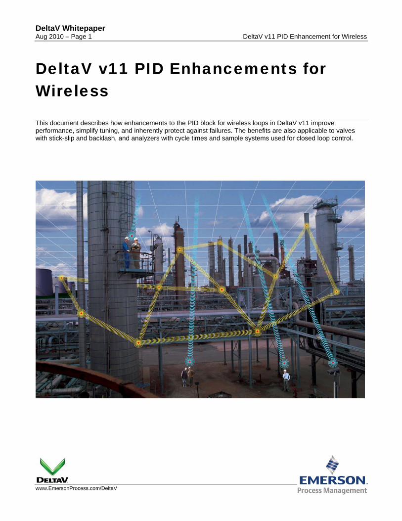
DeltaV Whitepaper Aug 2010 – Page 1 DeltaV v11 PID Enhancement for Wireless www.EmersonProcess.com/DeltaV DeltaV v11 PID Enhancements for Wireless This document describes how enhancements to the PID block for wireless loops in DeltaV v11 improve performance, simplify tuning, and inherently protect against failures. The benefits are also applicable to valves with stick-slip and backlash, and analyzers with cycle times and sample systems used for closed loop control.
Transcript of DeltaV v11 PID Enhancements for Wireless · DeltaV Whitepaper Aug 2010 – Page 1 DeltaV v11 PID...
DeltaV Whitepaper Aug 2010 – Page 1 DeltaV v11 PID Enhancement for Wireless
www.EmersonProcess.com/DeltaV
DeltaV v11 PID Enhancements for Wireless This document describes how enhancements to the PID block for wireless loops in DeltaV v11 improve performance, simplify tuning, and inherently protect against failures. The benefits are also applicable to valves with stick-slip and backlash, and analyzers with cycle times and sample systems used for closed loop control.
DeltaV Whitepaper Aug 2010 – Page 2 DeltaV v11 PID Enhancement for Wireless
Table of Contents
Executive Summary................................................................................................................. 3
Introduction and Overview ..................................................................................................... 3
Target Applications ................................................................................................................. 6
Test Setup ................................................................................................................................ 6
Discussion of Test Results..................................................................................................... 8
Summary of Test Results...................................................................................................... 13
Conclusion ............................................................................................................................. 13
Resources .............................................................................................................................. 14
Appendix A - PIDPlus Algorithm .......................................................................................... 14
DeltaV Whitepaper Aug 2010 – Page 3 DeltaV v11 PID Enhancement for Wireless
Executive Summary Wireless measurements reduce wiring installation and maintenance costs and eliminate electrical noise and ground loops. The portability of wireless transmitters offers opportunities to troubleshoot locations in the process with abnormal operations and to demonstrate process control improvements and online process and equipment metrics such as yield, reaction rate, energy use, and fouling. The PIDPlus in DeltaV v11 has enhancements that deliver the following benefits in control applications:
• Inherent prevention of process oscillations from update delay, sensitivity limits, and failures that are observed when a traditional PID is used for wireless measurements, analyzers, and sticky valves.
• Reduction of the integrated absolute error (total error) and peak error (maximum error) for unmeasured load disturbances when the update time is significant compared to the process response time. For set point changes, the overshoot, rise time (time to reach setpoint), and settling time are decreased.
• Standard tuning for maximum load rejection may be applied independent of the measurement update time whereas the traditional PID requires special detuning to stabilize the loop for large update times.
The primary benefits are less off-spec material (less recycle, downgraded product, or waste) from lower integrated absolute error, greater on-stream time (less trips and damage) from smaller peak errors and overshoot, and faster startup and batch cycle times from shorter rise and settling times to achieve new setpoints. The PIDPlus delivers similar benefits when used with analyzers that have sample systems.
Introduction and Overview It is widely recognized that wireless measurements considerably reduce installation and maintenance costs. However, it is less recognized that the portability of wireless offers the ability to optimize the measurement location for the fastest most representative process response and to demonstrate/prototype process control improvement for finding and justifying permanent solutions.
The wireless update time termed “default update rate” (refresh time) is the time interval for periodic reporting. The wireless update sensitivity termed “trigger level” is the minimum change in measurement value for exception reporting. To save power, the transmitter goes to sleep and wakes up periodically to check if the change in sensor value from the last value transmitted is larger than the trigger level. When the change exceeds the trigger level or the time since the last communication exceeds the default update rate, then the value is transmitted. The time interval between periodic checks of the sensor is the “triggered update rate” (wakeup time). If only periodic reporting is available, this time interval is the default update rate. Increases in the default update rate and trigger level settings reduce the number of transmissions, which increases battery life. The PIDPlus eliminates the ramps, limit cycles, and spikes from large values of these settings facilitating an increase in battery life.
For slow processes where a significant process response takes minutes to hours to develop, such as composition, level, and temperature in large volumes, wireless measurements are fast enough for closed loop control using traditional PID. The primary question for these applications is what is the potential detrimental effect of a loss of update and poor sensitivity? The PIDPlus protects against communication, sensor, valve, and analyzer failures and eliminates the cycling from wireless exception reporting, sensor, valve, or analyzer sensitivity limits for these and other loops. Thus, the PIDPlus improves the reliability and reduces the variability for all loops with and without wireless measurements. Additionally the PIDPlus extends the applicability of wireless measurements and analyzers to processes with a response time faster than the update time.
DeltaV Whitepaper Aug 2010 – Page 4 DeltaV v11 PID Enhancement for Wireless
While the PIDPlus offers advantages for all loops, wireless measurements should not be used where the process can cause product degradation, shutdowns, equipment damage, or an unsafe condition faster than the triggered update rate (exception reporting) or default update rate (periodic reporting) of the wireless transmitter. Examples of loops that can get into trouble too fast for even the fastest wireless update time are sheet, compressor, and turbine speed control and incinerator and pipeline pressure control. Slow wireless default update rates, such as 30 and 60 seconds, can be a problem for vessel or header pressure control since the pressure may approach alarm, trip, or relief settings within the default update rate.
In a traditional PID, the integral and derivative modes are computed each execution of the PID block. The PID algorithm uses the execution time in the integral and derivative mode calculations. Thus, the reset and derivative contribution calculated by traditional PID may not be appropriate when used with a wireless measurement where the default update rate is significant compared to the process response time. In such cases, the traditional PID will ramp the controller output through continual integral action even though the actual measurement has not changed. The PID is acting on old information. The detrimental effect of integral mode acting on old information is greatest if the process response has largely responded before the next update, which occurs when the process response is faster than the update time or the measurement value has not been updated because of device or communication failure. The update time of wireless measurements on fast processes, such as flow and pipeline temperature and pH loops, and the update time for analyzers in many applications are slower than the process response. An update failure occurs for loss of transmission, sensor failure, a stuck valve, and a sample or multiplexer system failure. Furthermore, when the wireless measurement is communicated using exception reporting, the ramp of the controller output between updates due to a sensitivity limit results in a perpetual equal amplitude oscillation called a limit cycle even though there are no load disturbances.
When there is an update, the traditional PID considers the entire change in the measurement value occurred within the PID execution time for the derivative mode calculation. The result when the PID is executed faster than the wireless default update rate is a spike in controller output whose size increases with the movement of the process between updates, which is greatest for a fast process or for recovery from an update failure.
The ramp, limit cycle, and spike from a traditional PID inflict a disturbance upon the loop and possibly other loops. Thus, a traditional PID in automatic mode can cause process variability even if there are no disturbances.
The PIDPlus computes the integral and derivative mode contributions to the controller output when there is a measurement update and uses the elapsed time between updates in its calculations. Thus, the PIDPlus only acts on new information and considers the observed change in the measurement to have occurred not in just the last PID execution time but over the elapsed time.
The use of a positive feedback network for the DeltaV PID reset calculation enables a further enhancement. If the reset time is set equal to the process time constant, which is the tuning method predominantly used within Emerson, the filter provides a model of the process’s exponential response for the integral mode response. The inclusion of the knowledge of the process response eliminates the need to detune the PID to suppress extensive oscillations when the update is much slower than the process response. For these cases, the controller gain can be set equal to the inverse of the controller gain to provide considerably tighter control.
When there is a loss of communication with the measurement or final control element (e.g. valve, damper, or variable speed drive), the PIDPlus provides no further reset action. The PIDPlus waits for new information whereas the traditional PID output ramps to an output limit. When communication is restored, the PIDPlus acts on the new information only. The traditional PID sees the effect of the ramp to the output limit that occurred during the loss of communication or loss of valve travel. Additionally, the traditional PID considers the entire observed change to have occurred within the last execution of the PID instead of the time duration of the failure. The result is a bump from gain action and spike from rate action in the traditional PID output.
DeltaV Whitepaper Aug 2010 – Page 5 DeltaV v11 PID Enhancement for Wireless
The PIDPlus executes as fast as a traditional PID independent of the wireless default update rate or analyzer cycle and sample time. As a result, PIDPlus is ready to immediately act on changes in setpoint, mode, remote output, feedforward, and tuning. For a proportional gain that is the inverse of the process gain, the setpoint response is particularly impressive in that the controller output goes to the value needed to reach setpoint within the PID execution time. For a fast loop, the process is already at the setpoint before the next update.
Secondary loops are designed to be faster than primary loops for cascade control. If a wireless measurement is used in a secondary loop, the PIDPlus can prevent the secondary loop response from becoming too slow. The fast load response of the PIDPlus helps the secondary loop reject secondary disturbances. The fast setpoint response of the PIDPlus helps the primary loop reach its setpoint faster and reject primary loop disturbances.
Analyzers with sample systems offer a higher level of control. Ultimately you want to know and control is the composition in a process stream. However, the use of analyzers for closed loop control is rather limited due to the long update time, excessive interruptions and extraneous values, and low sensitivity. Analyzer sensitivity is generally not as good as flow, pH, pressure, and temperature measurement sensitivity. The analyzer sensitivity limit is the result of interferences, analysis method, and sensor sensitivity. Analyzer update time, poor sensitivity, and noise results in a step response that precludes the use rate action even if the process time constant is large. The PIDPlus eliminates most of these concerns and enables more analyzers to go on closed loop control.
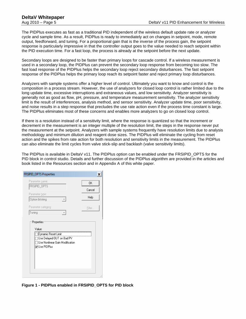
If there is a resolution instead of a sensitivity limit, where the response is quantized so that the increment or decrement in the measurement is an integer multiple of the resolution limit, the steps in the response never put the measurement at the setpoint. Analyzers with sample systems frequently have resolution limits due to analysis methodology and minimum dilution and reagent dose sizes. The PIDPlus will eliminate the cycling from reset action and the spikes from rate action for both resolution and sensitivity limits in the measurement. The PIDPlus can also eliminate the limit cycles from valve stick-slip and backlash (valve sensitivity limits). The PIDPlus is available in DeltaV v11. The PIDPlus option can be enabled under the FRSIPID_OPTS for the PID block in control studio. Details and further discussion of the PIDPlus algorithm are provided in the articles and book listed in the Resources section and in Appendix A of this white paper.
Figure 1 - PIDPlus enabled in FRSIPID_OPTS for PID block

DeltaV Whitepaper Aug 2010 – Page 6 DeltaV v11 PID Enhancement for Wireless
Target Applications While the PIDPlus can be used in any application to reduce process variability and provide protection against measurement and valve failures, the greatest benefits are seen for loops where the:
Update time is larger than the process response time
Update sensitivity limit is larger than the desired process precision
Update failures can occur
Valve exhibits significant stick-slip and backlash
Since the PIDPlus takes into account the effect of update time, the benefit is greatest where the wireless or analyzer update time is much larger than the process response time (defined here as the process deadtime plus time constant). The improvement in control loop response can be significant but diminishes as the update time decreases and approaches the process response time. For an update time that is less than the process response time, the larger benefit of PIDPlus is the protection against loss of communication or device failure or elimination of limit cycles from measurement and valve sensitivity limits.
Some examples of mainstream applications where PIDPlus provide greatest improvement in closed loop control are:
Wireless flow control
Wireless static mixer pH control
Wireless desuperheater temperature control
Pulp and paper stock consistency control
Cross directional (CD) control of sheet thickness
Analyzer control of pipeline composition
Analyzer control of plug flow reactor product composition
Examples of mainstream applications with less but still significant improvement in closed loop control are:
Wireless vessel pressure control
Wireless extruder temperature control
Wireless jacket temperature control
Wireless heat exchanger temperature control
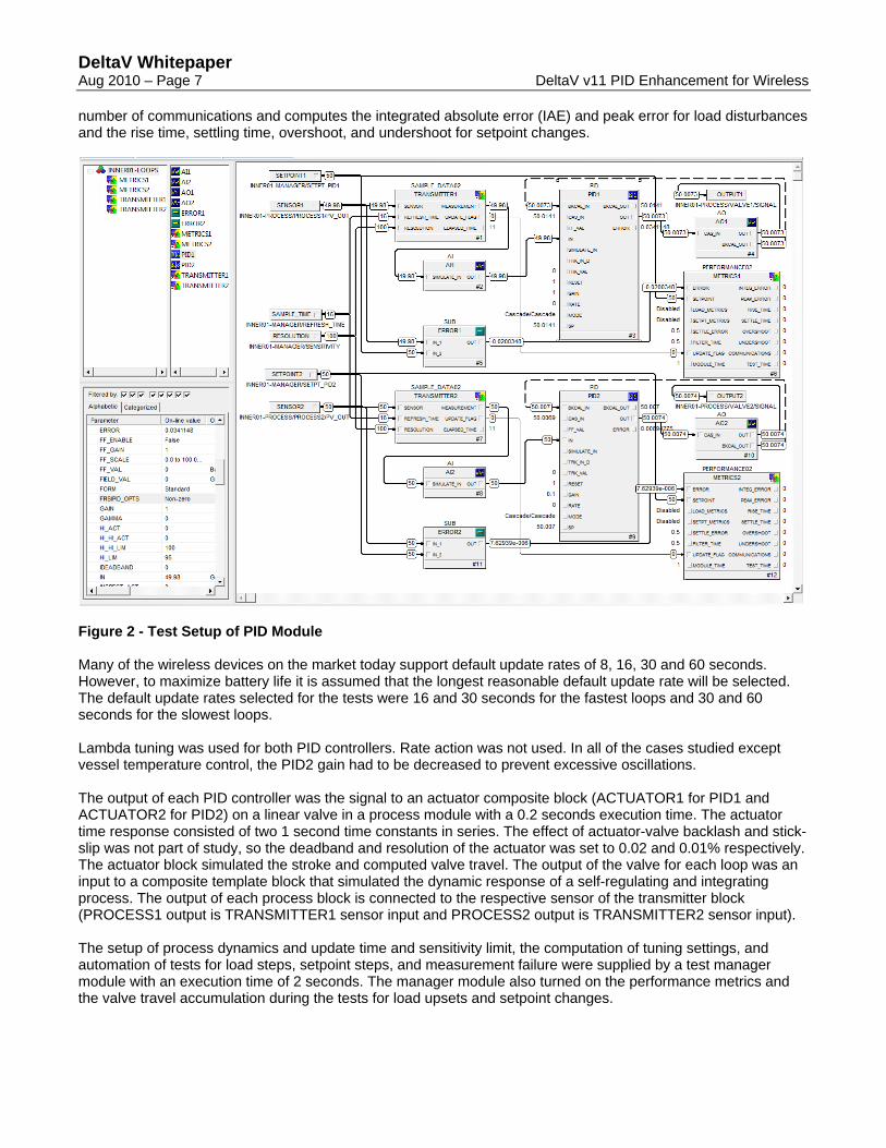
Test Setup A DeltaV v11 module with 1 second execution time was set up with two PID blocks. The first PID block (PID1) had the PIDPlus option enabled in the FRSIPID_OPTS parameter whereas the second PID block (PID2) did not. The PID analog inputs (AI1 for PID1 and AI2 for PID2) were provided by SAMPLE_DATA02 composite blocks that simulated the update time and sensitivity limits for wireless transmitters and analyzers (TRANSMITTER1 for PID1 and TRANSMITTER2 for PID2). A composite block (PERFORMANCE02) for performance metrics tallies the
DeltaV Whitepaper Aug 2010 – Page 7 DeltaV v11 PID Enhancement for Wireless
number of communications and computes the integrated absolute error (IAE) and peak error for load disturbances and the rise time, settling time, overshoot, and undershoot for setpoint changes.
Figure 2 - Test Setup of PID Module Many of the wireless devices on the market today support default update rates of 8, 16, 30 and 60 seconds. However, to maximize battery life it is assumed that the longest reasonable default update rate will be selected. The default update rates selected for the tests were 16 and 30 seconds for the fastest loops and 30 and 60 seconds for the slowest loops. Lambda tuning was used for both PID controllers. Rate action was not used. In all of the cases studied except vessel temperature control, the PID2 gain had to be decreased to prevent excessive oscillations. The output of each PID controller was the signal to an actuator composite block (ACTUATOR1 for PID1 and ACTUATOR2 for PID2) on a linear valve in a process module with a 0.2 seconds execution time. The actuator time response consisted of two 1 second time constants in series. The effect of actuator-valve backlash and stick-slip was not part of study, so the deadband and resolution of the actuator was set to 0.02 and 0.01% respectively. The actuator block simulated the stroke and computed valve travel. The output of the valve for each loop was an input to a composite template block that simulated the dynamic response of a self-regulating and integrating process. The output of each process block is connected to the respective sensor of the transmitter block (PROCESS1 output is TRANSMITTER1 sensor input and PROCESS2 output is TRANSMITTER2 sensor input). The setup of process dynamics and update time and sensitivity limit, the computation of tuning settings, and automation of tests for load steps, setpoint steps, and measurement failure were supplied by a test manager module with an execution time of 2 seconds. The manager module also turned on the performance metrics and the valve travel accumulation during the tests for load upsets and setpoint changes.
DeltaV Whitepaper Aug 2010 – Page 8 DeltaV v11 PID Enhancement for Wireless
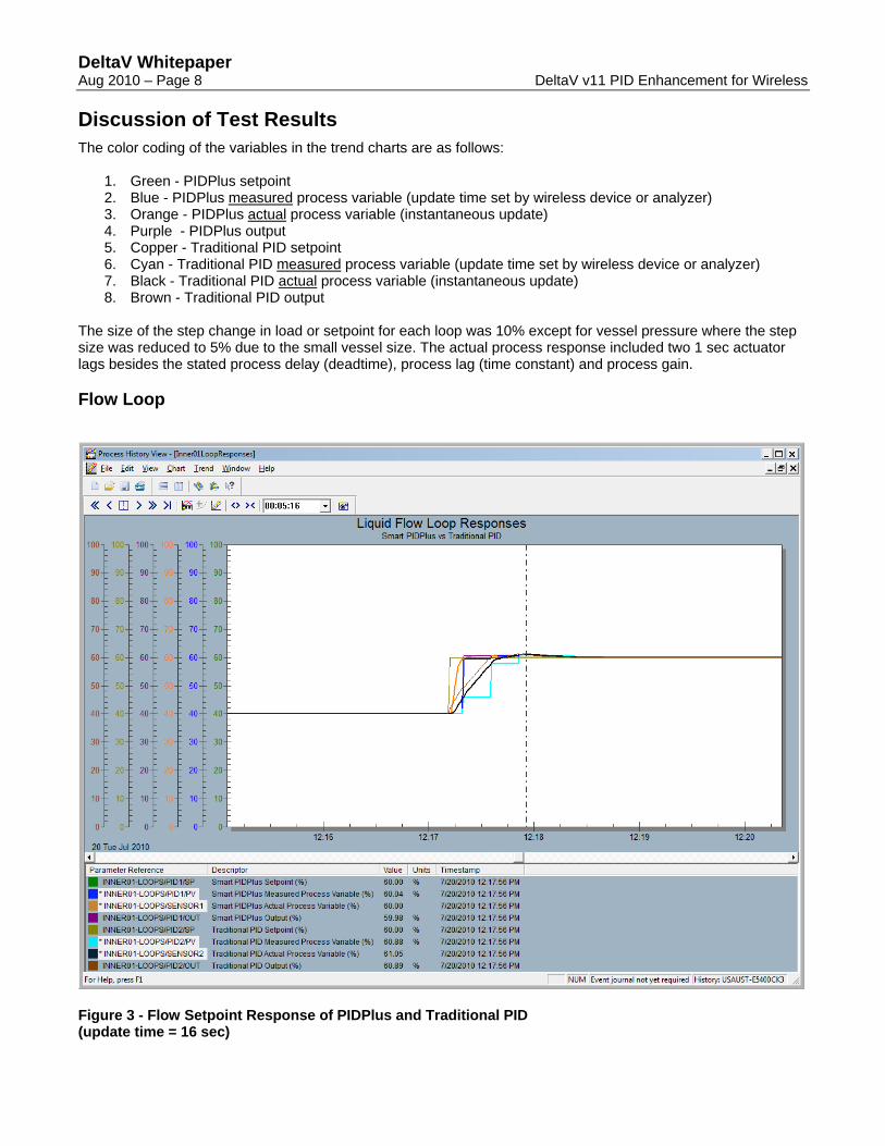
Discussion of Test Results The color coding of the variables in the trend charts are as follows:
1. Green - PIDPlus setpoint 2. Blue - PIDPlus measured process variable (update time set by wireless device or analyzer) 3. Orange - PIDPlus actual process variable (instantaneous update) 4. Purple - PIDPlus output 5. Copper - Traditional PID setpoint 6. Cyan - Traditional PID measured process variable (update time set by wireless device or analyzer) 7. Black - Traditional PID actual process variable (instantaneous update) 8. Brown - Traditional PID output
The size of the step change in load or setpoint for each loop was 10% except for vessel pressure where the step size was reduced to 5% due to the small vessel size. The actual process response included two 1 sec actuator lags besides the stated process delay (deadtime), process lag (time constant) and process gain. Flow Loop
Figure 3 - Flow Setpoint Response of PIDPlus and Traditional PID (update time = 16 sec)
DeltaV Whitepaper Aug 2010 – Page 9 DeltaV v11 PID Enhancement for Wireless
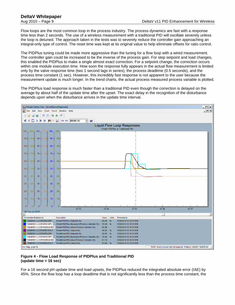
Flow loops are the most common loop in the process industry. The process dynamics are fast with a response time less than 2 seconds. The use of a wireless measurement with a traditional PID will oscillate severely unless the loop is detuned. The approach taken in the tests was to severely reduce the controller gain approaching an integral-only type of control. The reset time was kept at its original value to help eliminate offsets for ratio control. The PIDPlus tuning could be made more aggressive than the tuning for a flow loop with a wired measurement. The controller gain could be increased to be the inverse of the process gain. For step setpoint and load changes, this enabled the PIDPlus to make a single almost exact correction. For a setpoint change, the correction occurs within one module execution time. How soon the response fully appears in the actual flow measurement is limited only by the valve response time (two 1 second lags in series), the process deadtime (0.5 seconds), and the process time constant (1 sec). However, this incredibly fast response is not apparent to the user because the measurement update is much longer. In the trend charts, the actual process measured process variable is plotted. The PIDPlus load response is much faster than a traditional PID even though the correction is delayed on the average by about half of the update time after the upset. The exact delay in the recognition of the disturbance depends upon when the disturbance arrives in the update time interval.
Figure 4 - Flow Load Response of PIDPlus and Traditional PID (update time = 16 sec) For a 16 second pH update time and load upsets, the PIDPlus reduced the integrated absolute error (IAE) by 45%. Since the flow loop has a loop deadtime that is not significantly less than the process time constant, the
DeltaV Whitepaper Aug 2010 – Page 10 DeltaV v11 PID Enhancement for Wireless
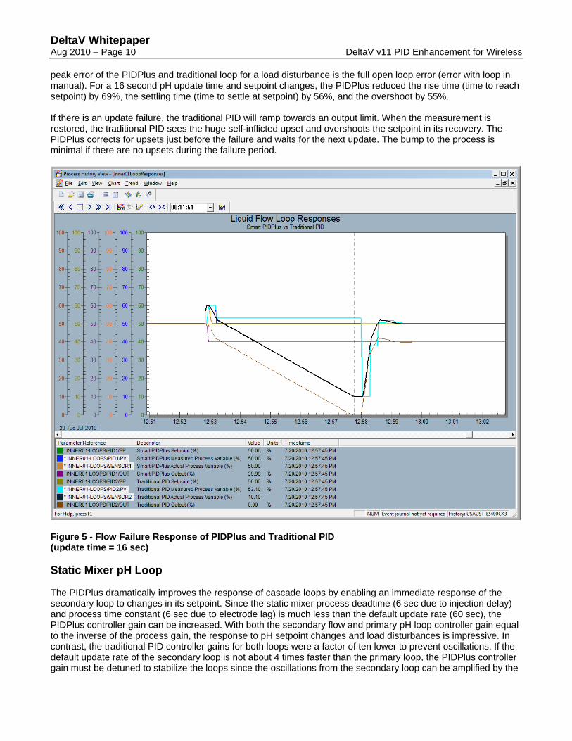
peak error of the PIDPlus and traditional loop for a load disturbance is the full open loop error (error with loop in manual). For a 16 second pH update time and setpoint changes, the PIDPlus reduced the rise time (time to reach setpoint) by 69%, the settling time (time to settle at setpoint) by 56%, and the overshoot by 55%. If there is an update failure, the traditional PID will ramp towards an output limit. When the measurement is restored, the traditional PID sees the huge self-inflicted upset and overshoots the setpoint in its recovery. The PIDPlus corrects for upsets just before the failure and waits for the next update. The bump to the process is minimal if there are no upsets during the failure period.
Figure 5 - Flow Failure Response of PIDPlus and Traditional PID (update time = 16 sec) Static Mixer pH Loop The PIDPlus dramatically improves the response of cascade loops by enabling an immediate response of the secondary loop to changes in its setpoint. Since the static mixer process deadtime (6 sec due to injection delay) and process time constant (6 sec due to electrode lag) is much less than the default update rate (60 sec), the PIDPlus controller gain can be increased. With both the secondary flow and primary pH loop controller gain equal to the inverse of the process gain, the response to pH setpoint changes and load disturbances is impressive. In contrast, the traditional PID controller gains for both loops were a factor of ten lower to prevent oscillations. If the default update rate of the secondary loop is not about 4 times faster than the primary loop, the PIDPlus controller gain must be detuned to stabilize the loops since the oscillations from the secondary loop can be amplified by the
DeltaV Whitepaper Aug 2010 – Page 11 DeltaV v11 PID Enhancement for Wireless
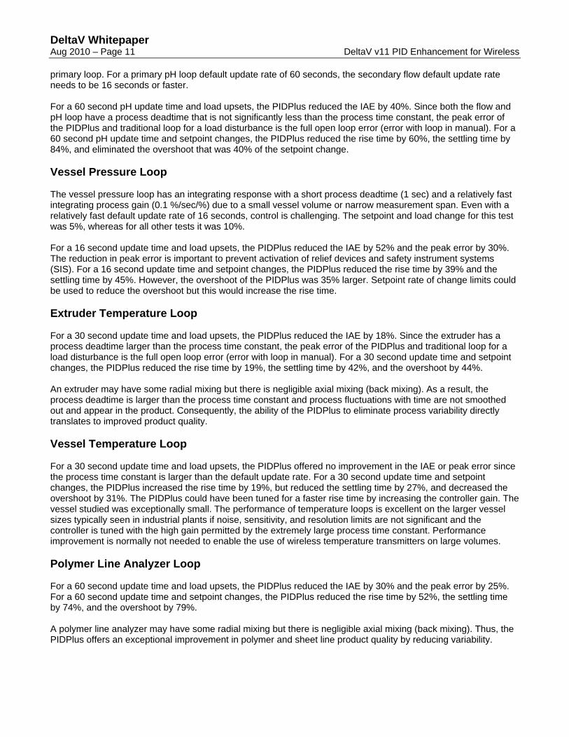
primary loop. For a primary pH loop default update rate of 60 seconds, the secondary flow default update rate needs to be 16 seconds or faster. For a 60 second pH update time and load upsets, the PIDPlus reduced the IAE by 40%. Since both the flow and pH loop have a process deadtime that is not significantly less than the process time constant, the peak error of the PIDPlus and traditional loop for a load disturbance is the full open loop error (error with loop in manual). For a 60 second pH update time and setpoint changes, the PIDPlus reduced the rise time by 60%, the settling time by 84%, and eliminated the overshoot that was 40% of the setpoint change. Vessel Pressure Loop The vessel pressure loop has an integrating response with a short process deadtime (1 sec) and a relatively fast integrating process gain (0.1 %/sec/%) due to a small vessel volume or narrow measurement span. Even with a relatively fast default update rate of 16 seconds, control is challenging. The setpoint and load change for this test was 5%, whereas for all other tests it was 10%. For a 16 second update time and load upsets, the PIDPlus reduced the IAE by 52% and the peak error by 30%. The reduction in peak error is important to prevent activation of relief devices and safety instrument systems (SIS). For a 16 second update time and setpoint changes, the PIDPlus reduced the rise time by 39% and the settling time by 45%. However, the overshoot of the PIDPlus was 35% larger. Setpoint rate of change limits could be used to reduce the overshoot but this would increase the rise time. Extruder Temperature Loop For a 30 second update time and load upsets, the PIDPlus reduced the IAE by 18%. Since the extruder has a process deadtime larger than the process time constant, the peak error of the PIDPlus and traditional loop for a load disturbance is the full open loop error (error with loop in manual). For a 30 second update time and setpoint changes, the PIDPlus reduced the rise time by 19%, the settling time by 42%, and the overshoot by 44%. An extruder may have some radial mixing but there is negligible axial mixing (back mixing). As a result, the process deadtime is larger than the process time constant and process fluctuations with time are not smoothed out and appear in the product. Consequently, the ability of the PIDPlus to eliminate process variability directly translates to improved product quality. Vessel Temperature Loop For a 30 second update time and load upsets, the PIDPlus offered no improvement in the IAE or peak error since the process time constant is larger than the default update rate. For a 30 second update time and setpoint changes, the PIDPlus increased the rise time by 19%, but reduced the settling time by 27%, and decreased the overshoot by 31%. The PIDPlus could have been tuned for a faster rise time by increasing the controller gain. The vessel studied was exceptionally small. The performance of temperature loops is excellent on the larger vessel sizes typically seen in industrial plants if noise, sensitivity, and resolution limits are not significant and the controller is tuned with the high gain permitted by the extremely large process time constant. Performance improvement is normally not needed to enable the use of wireless temperature transmitters on large volumes. Polymer Line Analyzer Loop For a 60 second update time and load upsets, the PIDPlus reduced the IAE by 30% and the peak error by 25%. For a 60 second update time and setpoint changes, the PIDPlus reduced the rise time by 52%, the settling time by 74%, and the overshoot by 79%. A polymer line analyzer may have some radial mixing but there is negligible axial mixing (back mixing). Thus, the PIDPlus offers an exceptional improvement in polymer and sheet line product quality by reducing variability.
DeltaV Whitepaper Aug 2010 – Page 12 DeltaV v11 PID Enhancement for Wireless
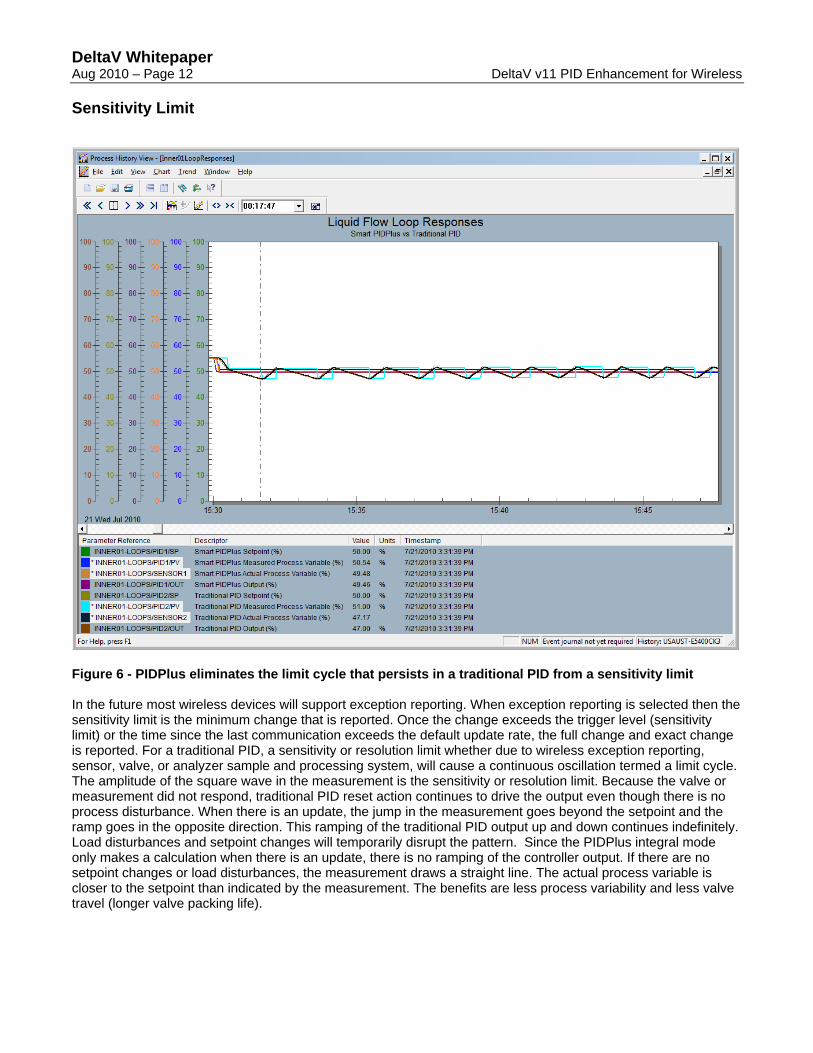
Sensitivity Limit
Figure 6 - PIDPlus eliminates the limit cycle that persists in a traditional PID from a sensitivity limit In the future most wireless devices will support exception reporting. When exception reporting is selected then the sensitivity limit is the minimum change that is reported. Once the change exceeds the trigger level (sensitivity limit) or the time since the last communication exceeds the default update rate, the full change and exact change is reported. For a traditional PID, a sensitivity or resolution limit whether due to wireless exception reporting, sensor, valve, or analyzer sample and processing system, will cause a continuous oscillation termed a limit cycle. The amplitude of the square wave in the measurement is the sensitivity or resolution limit. Because the valve or measurement did not respond, traditional PID reset action continues to drive the output even though there is no process disturbance. When there is an update, the jump in the measurement goes beyond the setpoint and the ramp goes in the opposite direction. This ramping of the traditional PID output up and down continues indefinitely. Load disturbances and setpoint changes will temporarily disrupt the pattern. Since the PIDPlus integral mode only makes a calculation when there is an update, there is no ramping of the controller output. If there are no setpoint changes or load disturbances, the measurement draws a straight line. The actual process variable is closer to the setpoint than indicated by the measurement. The benefits are less process variability and less valve travel (longer valve packing life).
DeltaV Whitepaper Aug 2010 – Page 13 DeltaV v11 PID Enhancement for Wireless
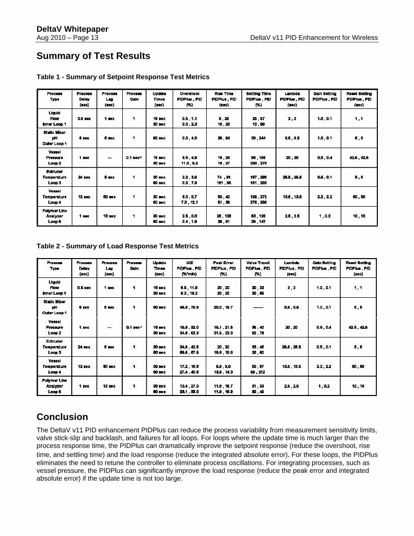
Summary of Test Results Table 1 - Summary of Setpoint Response Test Metrics
Table 2 - Summary of Load Response Test Metrics
Conclusion The DeltaV v11 PID enhancement PIDPlus can reduce the process variability from measurement sensitivity limits, valve stick-slip and backlash, and failures for all loops. For loops where the update time is much larger than the process response time, the PIDPlus can dramatically improve the setpoint response (reduce the overshoot, rise time, and settling time) and the load response (reduce the integrated absolute error). For these loops, the PIDPlus eliminates the need to retune the controller to eliminate process oscillations. For integrating processes, such as vessel pressure, the PIDPlus can significantly improve the load response (reduce the peak error and integrated absolute error) if the update time is not too large.
DeltaV Whitepaper Aug 2010 – Page 14 DeltaV v11 PID Enhancement for Wireless
Resources (1) McMillan, Greg, “Opportunities for smart wireless pH, conductivity measurements”, InTech, 2010, Jan-
Feb, Web Exclusive (2) McMillan, Greg, “Wireless – overcoming challenges of PID control & analyzer applications”, InTech, 2010,
July-Aug (3) McMillan, Greg, Essentials of Modern Measurements and Final Elements for the Process Industry, ISA,
2010 (4) McMillan, Greg, “Is Wireless Control Ready for Prime Time”, Control, 2009, May (5) Blevins, Terry et. al., “Improving PID Control with Unreliable Communications”, ISA Expo, Houston, 2006 (6) Blevins, Terry et. al., “Similarity-based Traffic Reduction to Increase Battery Life in a Wireless Process
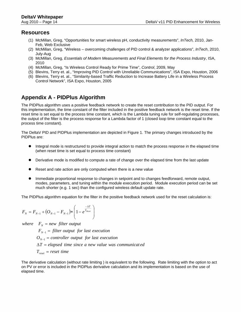
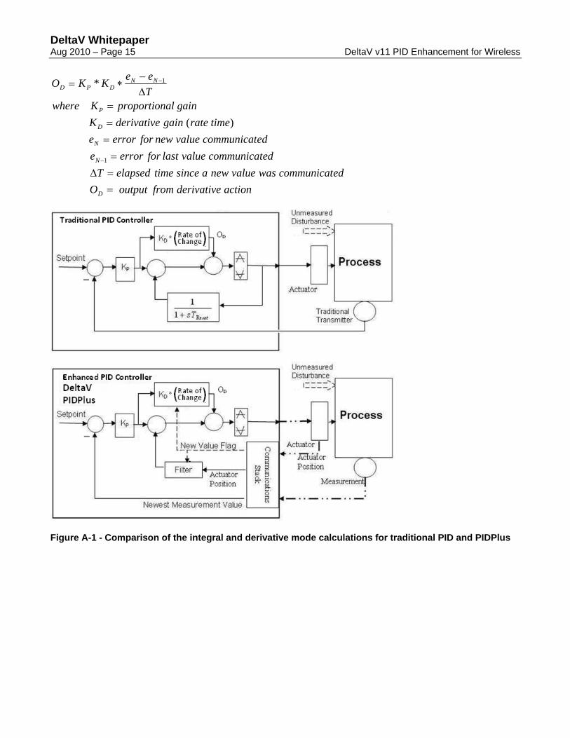
Control Network”, ISA Expo, Houston, 2005 Appendix A - PIDPlus Algorithm The PIDPlus algorithm uses a positive feedback network to create the reset contribution to the PID output. For this implementation, the time constant of the filter included in the positive feedback network is the reset time. If the reset time is set equal to the process time constant, which is the Lambda tuning rule for self-regulating processes, the output of the filter is the process response for a Lambda factor of 1 (closed loop time constant equal to the process time constant).
The DeltaV PID and PIDPlus implementation are depicted in Figure 1. The primary changes introduced by the PIDPlus are:
Integral mode is restructured to provide integral action to match the process response in the elapsed time (when reset time is set equal to process time constant)
Derivative mode is modified to compute a rate of change over the elapsed time from the last update
Reset and rate action are only computed when there is a new value
Immediate proportional response to changes in setpoint and to changes feedforward, remote output, modes, parameters, and tuning within the module execution period. Module execution period can be set much shorter (e.g. 1 sec) than the configured wireless default update rate.
The PIDPlus algorithm equation for the filter in the positive feedback network used for the reset calculation is:
( )
timeresetTedcommunicatwasvaluenewasincetimeelapsedT
executionlastforoutputcontrollerOexecutionlastforoutputfilterF
outputfilternewFwhere
eFOFF
reset
N
N
N
TT
NNNNReset
==Δ==
=
⎟⎟⎠
⎞⎜⎜⎝
⎛−∗−+=
−
−
Δ−
−−−
1
1
111 1
The derivative calculation (without rate limiting ) is equivalent to the following. Rate limiting with the option to act on PV or error is included in the PIDPlus derivative calculation and its implementation is based on the use of elapsed time.
DeltaV Whitepaper Aug 2010 – Page 15 DeltaV v11 PID Enhancement for Wireless
actionderivativefrom outputOedcommunicatwasvaluenewasincetimeelapsedT
edcommunicatvaluelastforerroreedcommunicatvaluenewforerrore
timerategainderivativeKgainalproportionKwhere
TeeKKO
D
N
N
D
P
NNDPD
==Δ=
===
Δ−
∗=
−
−
1
1
)(
*
Figure A-1 - Comparison of the integral and derivative mode calculations for traditional PID and PIDPlus
DeltaV Whitepaper Aug 2010 – Page 16 DeltaV v11 PID Enhancement for Wireless
To locate a sales office near you, visit our website at: www.EmersonProcess.com/DeltaV Or call us at: Asia Pacific: 65.777.8211 Europe, Middle East: 41.41.768.6111 North America, Latin America: +1 800.833.8314 or +1 512.832.3774
For large power, water, and wastewater applications contact Power and Water Solutions at: www.EmersonProcess-powerwater.com Or call us at: Asia Pacific: 65.777.8211 Europe, Middle East, Africa: 48.22.630.2443 North America, Latin America: +1 412.963.4000
© Emerson Process Management 2009. All rights reserved. For Emerson Process Management trademarks and service marks, go to: http://www.emersonprocess.com/home/news/resources/marks.pdf. The contents of this publication are presented for informational purposes only, and while every effort has been made to ensure their accuracy, they are not to be construed as warrantees or guarantees, express or implied, regarding the products or services described herein or their use or applicability. All sales are governed by our terms and conditions, which are available on request. We reserve the right to modify or improve the design or specification of such products at any time without notice. www.EmersonProcess.com/DeltaV
This page intentionally left blank.