Delta VFD-B Series - Movaria El Salvador Brochure...O u t p u t I n p u t Model VFD B 007 015 022...
4
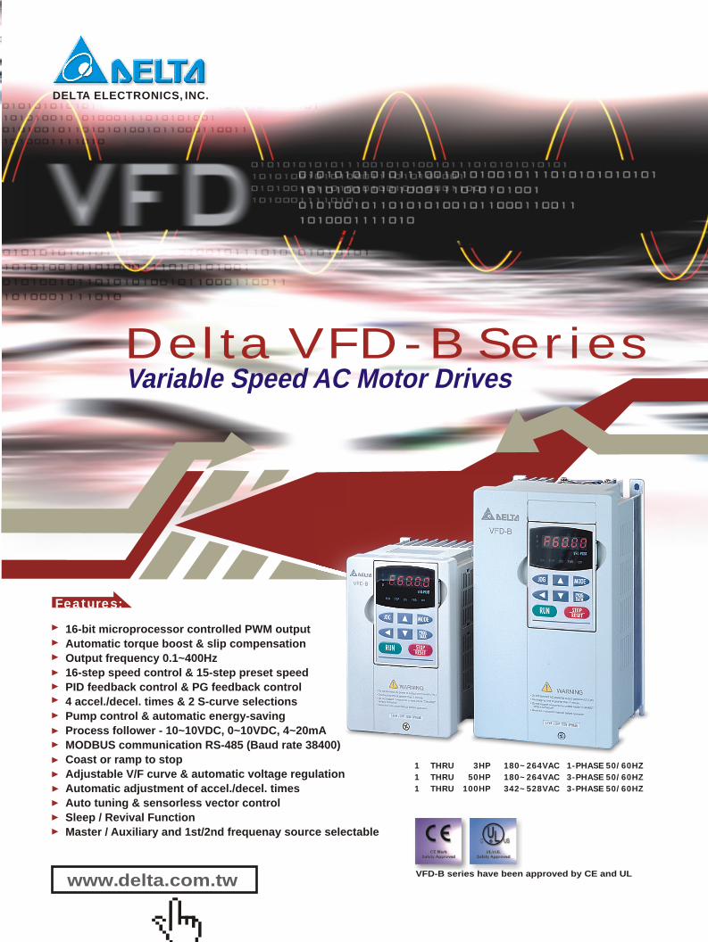
Variable Speed AC Motor Drives Features: 1 THRU 3HP 180~264VAC 1-PHASE 50/60HZ 1 THRU 50HP 180~264VAC 3-PHASE 50/60HZ 1 THRU 100HP 342~528VAC 3-PHASE 50/60HZ VFD-B series have been approved by CE and UL DELTA ELECTRONICS, INC. Delta VFD-B Series 16-bit microprocessor controlled PWM output Automatic torque boost & slip compensation Output frequency 0.1~400Hz 16-step speed control & 15-step preset speed PID feedback control & PG feedback control 4 accel./decel. times & 2 S-curve selections Pump control & automatic energy-saving Process follower - 10~10VDC, 0~10VDC, 4~20mA MODBUS communication RS-485 (Baud rate 38400) Coast or ramp to stop Adjustable V/F curve & automatic voltage regulation Automatic adjustment of accel./decel. times Auto tuning & sensorless vector control Sleep / Revival Function Master / Auxiliary and 1st/2nd frequenay source selectable www.delta.com.tw
Transcript of Delta VFD-B Series - Movaria El Salvador Brochure...O u t p u t I n p u t Model VFD B 007 015 022...
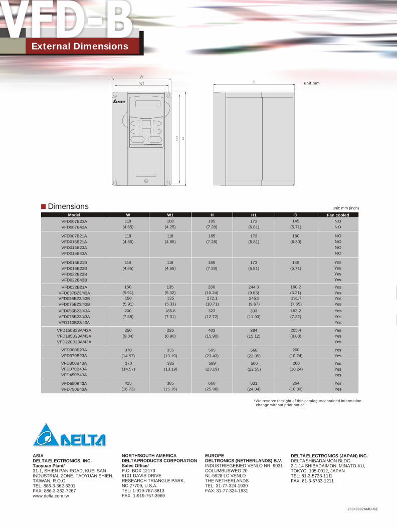
unit: mm (inch) DimensionsModel
VFD007B23A
VFD007B43A
VFD007B21A
VFD015B21A
VFD015B23A
VFD015B43A
VFD015B21B
VFD015B23B
VFD022B23B
VFD022B43B
VFD022B21A
VFD037B23/43A
VFD055B23/43B
VFD075B23/43B
VFD055B23/43A
VFD075B23/43A
VFD110B23/43A
VFD150B23A/43A
VFD185B23A/43A
VFD220B23A/43A
VFD300B23A
VFD370B23A
VFD300B43A
VFD370B43A
VFD450B43A
VFD550B43A
VFD750B43A
W
118
(4.65)
118
(4.65)
118
(4.65)
150
(5.91)
200
(7.88)
250
(9.84)
370
(14.57)
370
(14.57)
425
(16.73)
W1
108
(4.25)
118
(4.65)
118
(4.65)
135
(5.32)
185.6
(7.31)
226
(8.90)
335
(13.19)
335
(13.19)
385
(15.16)
150
(5.91)
H
185
(7.28)
185
(7.28)
185
(7.28)
260
(10.24)
323
(12.72)
403
(15.90)
595
(23.43)
589
(23.19)
660
(25.98)
135
(5.31)
272.1
(10.71)
H1
173
(6.81)
173
(6.81)
173
(6.81)
244.3
(9.63)
303
(11.93)
384
(15.12)
560
(22.05)
560
(22.55)
631
(24.84)
245.5
(9.67)
D
145
(5.71)
160
(6.30)
145
(5.71)
160.2
(6.31)
183.2
(7.22)
205.4
(8.08)
260
(10.24)
260
(10.24)
264
(10.39)
191.7
(7.55)
Fan cooled
NO
NO
NO
NO
NO
NO
Yes
Yes
Yes
Yes
Yes
Yes
Yes
Yes
Yes
Yes
Yes
Yes
Yes
Yes
Yes
Yes
Yes
Yes
Yes
Yes
Yes
Variable Speed AC Motor Drives
Features:
unit:mm
External Dimensions
1 THRU 3HP 180~264VAC 1-PHASE 50/60HZ
1 THRU 50HP 180~264VAC 3-PHASE 50/60HZ
1 THRU 100HP 342~528VAC 3-PHASE 50/60HZ
VFD-B series have been approved by CE and UL
ASIADELTA ELECTRONICS, INC.Taoyuan Plant/31-1, SHIEN PAN ROAD, KUEI SAN INDUSTRIAL ZONE, TAOYUAN SHIEN, TAIWAN, R.O.C.TEL: 886-3-362-6301FAX: 886-3-362-7267www.delta.com.tw
NORTH/SOUTH AMERICADELTA PRODUCTS CORPORATIONSales Office/P.O. BOX 121735101 DAVIS DRIVERESEARCH TRIANGLE PARK,NC 27709, U.S.A.TEL: 1-919-767-3813FAX: 1-919-767-3969
EUROPEDELTRONICS (NETHERLANDS) B.V.INDUSTRIEGEBIED VENLO NR. 9031COLUMBUSWEG 20NL-5928 LC VENLOTHE NETHERLANDSTEL: 31-77-324-1930FAX: 31-77-324-1931
DELTA ELECTRONICS (JAPAN) INC.DELTA SHIBADAIMON BLDG. 2-1-14 SHIBADAIMON, MINATO-KU, TOKYO, 105-0012, JAPANTEL: 81-3-5733-1111FAX: 81-3-5733-1211
20040302AMD-SE
DELTA ELECTRONICS, INC.
Delta VFD-B Series
16-bit microprocessor controlled PWM output
Automatic torque boost & slip compensation
Output frequency 0.1~400Hz
16-step speed control & 15-step preset speed
PID feedback control & PG feedback control
4 accel./decel. times & 2 S-curve selections
Pump control & automatic energy-saving
Process follower - 10~10VDC, 0~10VDC, 4~20mA
MODBUS communication RS-485 (Baud rate 38400)
Coast or ramp to stop
Adjustable V/F curve & automatic voltage regulation
Automatic adjustment of accel./decel. times
Auto tuning & sensorless vector control
Sleep / Revival Function
Master / Auxiliary and 1st/2nd frequenay source selectable
www.delta.com.tw
*We reserve the right of this catalogue contained information change without prior notice.

Ou
tpu
tIn
pu
t
Model VFD B 007 015 022 037 055 075 110 150 185 220 300 370
Max. Applicable Motor Output (kW) 0.75 1.5 2.2 3.7 5.5 7.5 11 15 18.5 22 30 37
Max. Applicable Motor Output (HP) 1 2 3 5 7.5 10 15 20 25 30 40 50
Rated Capacity (kVA) 1.9 2.5 4.2 6.5 9.5 12.5 18.3 24.7 28.6 34.3 45.7 55
Rated Current (A) 5.0 7.0 11 17 25 33 49 65 75 90 120 145
Output Frequency Range 0.1~400Hz
Overload Endurance 150% f rated current for 60 seconds
Voltage Proportional to input voltage
Phase Voltage
ccc
o
Hz 1/3-Phase 3-Phase 200~240Vac 50/60Hz
Voltage Frequency Tolerance Voltage: 10% Frequency: 5%
Input Current (A) 11.9/5.7 15.3/7.6 22/15.5 20.6 26 34 50 60 75 90 110 142
Single (3-phase Input Current) 7.0 9.4 14.0 -
Cooling Method Natural Fan Cooled
Weight (Kg) 2.7 3.2 4.5 3 8 10 13 13 13 13 36 36
Model VFD 007 015 022 037 055 075 110 150 185 220 300 370 450 550 750
Max. Applicable Motor Output (kW) 0.75 1.5 2.2 3.7 5.5 7.5 11 15 18.5 22 30 37 45 55 75
Max. Applicable Motor Output (HP) 1 2 3 5 7.5 10 15 20 25 30 40 50 60 75 100
Rated Capacity (kVA) 2.3 3.2 4.2 6.5 9.9 13.7 18.3 24.4 28.9 34.3 45.7 55.6 69.3 84 114
Rated Current (A) 2.7 4.2 5.5 8.5 13 18 24 32 38 45 60 73 91 110 150
Output Frequency Range 0.1~400Hz
Overload Endurance 150% f rated current for 60 seconds
Voltage Proportional to input voltage
Phase Voltage
cccB
o
Hz 3-Phase 380~480Vac 50/60Hz
Voltage Frequency Tolerance Voltage: 10% Frequency: 5%
Input Current (A) 3.2 4.3 5.9 11.2 14 19 25 32 39 49 60 63 90 130 160
Cooling Method Natural Fan Cooled
Weight (Kg) 2.7 3.2 4.5 3 8 10 13 13 13 13 36 36 36 50 50
230V Series 1-Phase/3-Phase
460V Series 3-Phase
Ou
tpu
tIn
pu
t
Control System SPWM control (V/F or sensorless vector control)
Output Freq. Range 0.10~400Hz
Freq. Setting Resolution 0.01Hz
Output Freq. Resolution 0.01Hz
PWM Carrier Frequency Adjustable between 1 and 15 kHz
Auto torque, auto slip compensation, s
Skip Frequency Three zones, settings range 0.1-400Hz
Accel./Decel. Time 0.1 to 3600 seconds (4 independent settings for accel./decel. time)
Stall Prevention Level S
Operation frequency 0-400Hz, 0-100% rated current
Start time 0-25 seconds, stop time 0-25 seconds
Approx. 20% (up to 125% possible with option braking resistor Braking Torque braking unit externally mounted, 1-15HP braking transistor built-in)
V/F Pattern A
Frequency Keypad Set by
Setting External -10~+10VDC, 0~10VDC, 4~20mADC, communication (RS-485)
Operation Keypad Set by
S External Fwd/stop, rev/stop (run/stop, fwd/rev), 3-wire
Torque Boost tart torque: 150% at 1Hz
et current limit from 20%-250%
outputDC Injection Braking
or
djustable V/F pattern
ignals control, serial communication (RS-485)
Multi-speed selection 1 to 15, 1st/2nd/3rd/4th accel./decel. time selectionMulti-function Input Accel./decel. Inhibit, external baseblock, counter applicationsTerminal 15-step process control, disable auxiliary, jog, up/down command, sink/source selection
Drive operational, frequency attained signal, zero speed, setting auxiliaryMulti-function Output Overtorque detection, external baseblock detectionTerminal Under-voltage detection, keypad or external operation signal, alarm
Analog Output Select output frequency or current monitor
Alarm Output Contact 1 Form C contact or open collector output
PID control, fan & pump control, momentary power failure restart, AVR, external fault,
Fault retry, fault reset, 2 S-curves, fault records, frequency limit, digital frequency output,Operation Functions Parameter lockout, PG feedback control, auto tuning, REV run inhibit, stall prevention
Overvoltage, overcurrent, under-voltage, external trip, motor overloadProtective Functions Ground fault current, overload, overheat, IGBT short-circuit, Low carreut
8-key, 5-digit, 7-segment LED; 8 status LEDs, master frequency, output frequency,
Display Keypads Output current, custom units, parameter values for setup, review and faults,
RUN, STOP, RESET, FWD/REV, JOGo o oAmbient Temperature -10 +40 +50
o oemperature -20 +60
Pollution Degree 2
Ambient Humidity 90% RH or less (non-condensing )
Installation Location Altitude 1,000m or less, keep from corrosive gas, liquid and dust2 2 Vibration 9.81m/s (1G) less than 20Hz, 5.88m/s (0.6G) at 20 to 50Hz
C to C ( C without dust covers)
Storage T C to C
Op
era
tio
n s
pe
cif
ica
tio
nC
on
tro
l s
pe
cif
ica
tio
nE
nv
iro
nm
en
t
STOP JOGRUN
Standard wiring diagram Standard specifications
Standard specifications
* Three phase input power may apply to
single phase drives
* For the single phase application,
the AC input line can be connected to
any two of the three input terminals R,S,T.
Note: * is optional
*Braking resistor(optional) Refer to Appendix B for the use of special braking resistor
+1 +2/B1 B2
Jumper
VFDB
-(minus sign)
BR
BR
*DC chock (optional)
AVI
ACI
AUI
ACM
4~20mA
-10~+10V
+10V
5K
3
2
1
Power supply+10V 20mA
Master Frequency0 to 10V 47K
Analog Signal CommonE
FWD
REV
JOG
EF
MI1
MI2
MI3
MI4
MI6
TRG
MI5
DCM
+24V
Sw1
Sink
Source
Factory Default: SINK Mode
FWD/STOP
REV/STOP
JOG
E.F.
Multi-step 1
Multi-step 2
Multi-step 3
Multi-step 4
RESETAccel/Decel prohibit
Counter
Digital Signal Common
Factorydefault
* Don't apply the mains voltage directly to above terminals.
E
Please refer to Figure 4for wiring of SINKmode and SOURCEmode.
R(L1)
S(L2)
T(L3)
Fuse/NFB(None Fuse Breaker)
SA
OFF ON
MC
MC
RB
RC
Recommended Circuit when power supply is turned OFF by a fault output
R(L1)
S(L2)
T(L3)
E
Analog Multi-function OutputTerminalFactory default: Analog freq./ current meter 0~10VDC/2mA
MO3
U(T1)
V(T2)
W(T3)
IM3~
MO1
MO2
AFM
ACM
RA
RB
RC
MCM
RS-485
Motor
Factory default:indicates during operation48V50mA
Factory default:Freq. Setting Indication
Factory default:Low-voltage Indication
Multi-function Photocoulper Output
Analog Signal common
Serial interface1: EV 2: GND
5:NC 6: for communication
3: SG- 4: SG+
DFM
DCM
Digital Frequency OutputTerminalFactory default: 1:1 Duty=50%
Digital Signal Common
48V50mA
48V50mA
E
E
Please refer to “ControlTerminal Explanation”.
6 1
Main circuit (power) terminals Control circuit terminals Shielded leads & Cable

Ou
tpu
tIn
pu
t
Model VFD B 007 015 022 037 055 075 110 150 185 220 300 370
Max. Applicable Motor Output (kW) 0.75 1.5 2.2 3.7 5.5 7.5 11 15 18.5 22 30 37
Max. Applicable Motor Output (HP) 1 2 3 5 7.5 10 15 20 25 30 40 50
Rated Capacity (kVA) 1.9 2.5 4.2 6.5 9.5 12.5 18.3 24.7 28.6 34.3 45.7 55
Rated Current (A) 5.0 7.0 11 17 25 33 49 65 75 90 120 145
Output Frequency Range 0.1~400Hz
Overload Endurance 150% f rated current for 60 seconds
Voltage Proportional to input voltage
Phase Voltage
ccc
o
Hz 1/3-Phase 3-Phase 200~240Vac 50/60Hz
Voltage Frequency Tolerance Voltage: 10% Frequency: 5%
Input Current (A) 11.9/5.7 15.3/7.6 22/15.5 20.6 26 34 50 60 75 90 110 142
Single (3-phase Input Current) 7.0 9.4 14.0 -
Cooling Method Natural Fan Cooled
Weight (Kg) 2.7 3.2 4.5 3 8 10 13 13 13 13 36 36
Model VFD 007 015 022 037 055 075 110 150 185 220 300 370 450 550 750
Max. Applicable Motor Output (kW) 0.75 1.5 2.2 3.7 5.5 7.5 11 15 18.5 22 30 37 45 55 75
Max. Applicable Motor Output (HP) 1 2 3 5 7.5 10 15 20 25 30 40 50 60 75 100
Rated Capacity (kVA) 2.3 3.2 4.2 6.5 9.9 13.7 18.3 24.4 28.9 34.3 45.7 55.6 69.3 84 114
Rated Current (A) 2.7 4.2 5.5 8.5 13 18 24 32 38 45 60 73 91 110 150
Output Frequency Range 0.1~400Hz
Overload Endurance 150% f rated current for 60 seconds
Voltage Proportional to input voltage
Phase Voltage
cccB
o
Hz 3-Phase 380~480Vac 50/60Hz
Voltage Frequency Tolerance Voltage: 10% Frequency: 5%
Input Current (A) 3.2 4.3 5.9 11.2 14 19 25 32 39 49 60 63 90 130 160
Cooling Method Natural Fan Cooled
Weight (Kg) 2.7 3.2 4.5 3 8 10 13 13 13 13 36 36 36 50 50
230V Series 1-Phase/3-Phase
460V Series 3-Phase
Ou
tpu
tIn
pu
t
Control System SPWM control (V/F or sensorless vector control)
Output Freq. Range 0.10~400Hz
Freq. Setting Resolution 0.01Hz
Output Freq. Resolution 0.01Hz
PWM Carrier Frequency Adjustable between 1 and 15 kHz
Auto torque, auto slip compensation, s
Skip Frequency Three zones, settings range 0.1-400Hz
Accel./Decel. Time 0.1 to 3600 seconds (4 independent settings for accel./decel. time)
Stall Prevention Level S
Operation frequency 0-400Hz, 0-100% rated current
Start time 0-25 seconds, stop time 0-25 seconds
Approx. 20% (up to 125% possible with option braking resistor Braking Torque braking unit externally mounted, 1-15HP braking transistor built-in)
V/F Pattern A
Frequency Keypad Set by
Setting External -10~+10VDC, 0~10VDC, 4~20mADC, communication (RS-485)
Operation Keypad Set by
S External Fwd/stop, rev/stop (run/stop, fwd/rev), 3-wire
Torque Boost tart torque: 150% at 1Hz
et current limit from 20%-250%
outputDC Injection Braking
or
djustable V/F pattern
ignals control, serial communication (RS-485)
Multi-speed selection 1 to 15, 1st/2nd/3rd/4th accel./decel. time selectionMulti-function Input Accel./decel. Inhibit, external baseblock, counter applicationsTerminal 15-step process control, disable auxiliary, jog, up/down command, sink/source selection
Drive operational, frequency attained signal, zero speed, setting auxiliaryMulti-function Output Overtorque detection, external baseblock detectionTerminal Under-voltage detection, keypad or external operation signal, alarm
Analog Output Select output frequency or current monitor
Alarm Output Contact 1 Form C contact or open collector output
PID control, fan & pump control, momentary power failure restart, AVR, external fault,
Fault retry, fault reset, 2 S-curves, fault records, frequency limit, digital frequency output,Operation Functions Parameter lockout, PG feedback control, auto tuning, REV run inhibit, stall prevention
Overvoltage, overcurrent, under-voltage, external trip, motor overloadProtective Functions Ground fault current, overload, overheat, IGBT short-circuit, Low carreut
8-key, 5-digit, 7-segment LED; 8 status LEDs, master frequency, output frequency,
Display Keypads Output current, custom units, parameter values for setup, review and faults,
RUN, STOP, RESET, FWD/REV, JOGo o oAmbient Temperature -10 +40 +50
o oemperature -20 +60
Pollution Degree 2
Ambient Humidity 90% RH or less (non-condensing )
Installation Location Altitude 1,000m or less, keep from corrosive gas, liquid and dust2 2 Vibration 9.81m/s (1G) less than 20Hz, 5.88m/s (0.6G) at 20 to 50Hz
C to C ( C without dust covers)
Storage T C to C
Op
era
tio
n s
pe
cif
ica
tio
nC
on
tro
l s
pe
cif
ica
tio
nE
nv
iro
nm
en
t
STOP JOGRUN
Standard wiring diagram Standard specifications
Standard specifications
* Three phase input power may apply to
single phase drives
* For the single phase application,
the AC input line can be connected to
any two of the three input terminals R,S,T.
Note: * is optional
*Braking resistor(optional) Refer to Appendix B for the use of special braking resistor
+1 +2/B1 B2
Jumper
VFDB
-(minus sign)
BR
BR
*DC chock (optional)
AVI
ACI
AUI
ACM
4~20mA
-10~+10V
+10V
5K
3
2
1
Power supply+10V 20mA
Master Frequency0 to 10V 47K
Analog Signal CommonE
FWD
REV
JOG
EF
MI1
MI2
MI3
MI4
MI6
TRG
MI5
DCM
+24V
Sw1
Sink
Source
Factory Default: SINK Mode
FWD/STOP
REV/STOP
JOG
E.F.
Multi-step 1
Multi-step 2
Multi-step 3
Multi-step 4
RESETAccel/Decel prohibit
Counter
Digital Signal Common
Factorydefault
* Don't apply the mains voltage directly to above terminals.
E
Please refer to Figure 4for wiring of SINKmode and SOURCEmode.
R(L1)
S(L2)
T(L3)
Fuse/NFB(None Fuse Breaker)
SA
OFF ON
MC
MC
RB
RC
Recommended Circuit when power supply is turned OFF by a fault output
R(L1)
S(L2)
T(L3)
E
Analog Multi-function OutputTerminalFactory default: Analog freq./ current meter 0~10VDC/2mA
MO3
U(T1)
V(T2)
W(T3)
IM3~
MO1
MO2
AFM
ACM
RA
RB
RC
MCM
RS-485
Motor
Factory default:indicates during operation48V50mA
Factory default:Freq. Setting Indication
Factory default:Low-voltage Indication
Multi-function Photocoulper Output
Analog Signal common
Serial interface1: EV 2: GND
5:NC 6: for communication
3: SG- 4: SG+
DFM
DCM
Digital Frequency OutputTerminalFactory default: 1:1 Duty=50%
Digital Signal Common
48V50mA
48V50mA
E
E
Please refer to “ControlTerminal Explanation”.
6 1
Main circuit (power) terminals Control circuit terminals Shielded leads & Cable
unit: mm (inch) DimensionsModel
VFD007B23A
VFD007B43A
VFD007B21A
VFD015B21A
VFD015B23A
VFD015B43A
VFD015B21B
VFD015B23B
VFD022B23B
VFD022B43B
VFD022B21A
VFD037B23/43A
VFD055B23/43B
VFD075B23/43B
VFD055B23/43A
VFD075B23/43A
VFD110B23/43A
VFD150B23A/43A
VFD185B23A/43A
VFD220B23A/43A
VFD300B23A
VFD370B23A
VFD300B43A
VFD370B43A
VFD450B43A
VFD550B43A
VFD750B43A
W
118
(4.65)
118
(4.65)
118
(4.65)
150
(5.91)
200
(7.88)
250
(9.84)
370
(14.57)
370
(14.57)
425
(16.73)
W1
108
(4.25)
118
(4.65)
118
(4.65)
135
(5.32)
185.6
(7.31)
226
(8.90)
335
(13.19)
335
(13.19)
385
(15.16)
150
(5.91)
H
185
(7.28)
185
(7.28)
185
(7.28)
260
(10.24)
323
(12.72)
403
(15.90)
595
(23.43)
589
(23.19)
660
(25.98)
135
(5.31)
272.1
(10.71)
H1
173
(6.81)
173
(6.81)
173
(6.81)
244.3
(9.63)
303
(11.93)
384
(15.12)
560
(22.05)
560
(22.55)
631
(24.84)
245.5
(9.67)
D
145
(5.71)
160
(6.30)
145
(5.71)
160.2
(6.31)
183.2
(7.22)
205.4
(8.08)
260
(10.24)
260
(10.24)
264
(10.39)
191.7
(7.55)
Fan cooled
NO
NO
NO
NO
NO
NO
Yes
Yes
Yes
Yes
Yes
Yes
Yes
Yes
Yes
Yes
Yes
Yes
Yes
Yes
Yes
Yes
Yes
Yes
Yes
Yes
Yes
Variable Speed AC Motor Drives
Features:
unit:mm
External Dimensions
1 THRU 3HP 180~264VAC 1-PHASE 50/60HZ
1 THRU 50HP 180~264VAC 3-PHASE 50/60HZ
1 THRU 100HP 342~528VAC 3-PHASE 50/60HZ
VFD-B series have been approved by CE and UL
ASIADELTA ELECTRONICS, INC.Taoyuan Plant/31-1, SHIEN PAN ROAD, KUEI SAN INDUSTRIAL ZONE, TAOYUAN SHIEN, TAIWAN, R.O.C.TEL: 886-3-362-6301FAX: 886-3-362-7267www.delta.com.tw
NORTH/SOUTH AMERICADELTA PRODUCTS CORPORATIONSales Office/P.O. BOX 121735101 DAVIS DRIVERESEARCH TRIANGLE PARK,NC 27709, U.S.A.TEL: 1-919-767-3813FAX: 1-919-767-3969
EUROPEDELTRONICS (NETHERLANDS) B.V.INDUSTRIEGEBIED VENLO NR. 9031COLUMBUSWEG 20NL-5928 LC VENLOTHE NETHERLANDSTEL: 31-77-324-1930FAX: 31-77-324-1931
DELTA ELECTRONICS (JAPAN) INC.DELTA SHIBADAIMON BLDG. 2-1-14 SHIBADAIMON, MINATO-KU, TOKYO, 105-0012, JAPANTEL: 81-3-5733-1111FAX: 81-3-5733-1211
20040302AMD-SE
DELTA ELECTRONICS, INC.
Delta VFD-B Series
16-bit microprocessor controlled PWM output
Automatic torque boost & slip compensation
Output frequency 0.1~400Hz
16-step speed control & 15-step preset speed
PID feedback control & PG feedback control
4 accel./decel. times & 2 S-curve selections
Pump control & automatic energy-saving
Process follower - 10~10VDC, 0~10VDC, 4~20mA
MODBUS communication RS-485 (Baud rate 38400)
Coast or ramp to stop
Adjustable V/F curve & automatic voltage regulation
Automatic adjustment of accel./decel. times
Auto tuning & sensorless vector control
Sleep / Revival Function
Master / Auxiliary and 1st/2nd frequenay source selectable
www.delta.com.tw
*We reserve the right of this catalogue contained information change without prior notice.