Dell™ Remote Console Switch Software User's Guide · Contentsxxx|xxx3 Contents ProductOverview 7...
114
Dell™ Remote Console Switch Software User's Guide
Transcript of Dell™ Remote Console Switch Software User's Guide · Contentsxxx|xxx3 Contents ProductOverview 7...

Dell™ Remote Console SwitchSoftware User's Guide

NotesNOTE: A NOTE indicates important information that helps youmake better use of your computer.
Third Party Software. You acknowledge that the SOFTWARE PRODUCT may
contain or be provided with copyrighted software of Dell's suppliers as identified in
associated documentation or other printed or electronic materials (“Third Party
Software”) which are obtained under a license from such suppliers. Your use of any
such Third Party Software shall be subject to and you agree to comply with the
applicable restrictions and other terms and conditions set forth in such documentation
or materials as set forth in any “Third-Party Licenses ReadMe” file or similar file
located in the installation directory for the SOFTWARE PRODUCT.
Any open source software is distributed in the hope that it will be useful, but is
provided “as is” without any expressed or implied warranty; including but not limited
to the implied warranty of merchantability or fitness for a particular purpose. In no
event shall Dell, the copyright holders, or the contributors be liable for any direct,
indirect, incidental, special, exemplary, or consequential damages (including, but not
limited to, procurement of substitute goods or services; loss of use, data or profits; or
business interruption) however caused and on any theory of liability, whether in
contract, strict liability, or tort (including negligence or otherwise) arising in any way
out of the use of this software, even if advised of the possibility of such damage.
Reproduction of these materials in any manner whatsoever without the written
permission of Dell Inc. is strictly forbidden.
Trademarks used in this text: Dell, the DELL logo, and OpenManage are trademarks
of Dell Inc.; Intel Pentium is a registered trademark of Intel Corporation in the U.S.
and other countries; Microsoft, Windows, andWindows Vista are either trademarks or
registered trademarks of Microsoft Corporation in the United States and/or other
countries; Avocent is a registered trademark of Avocent Corporation or its affiliates
in the US and other countries; Red Hat and Red Hat Enterprise Linux are registered
trademarks of Red Hat, Inc. in the United States and other countries; SUSE is a
registered trademark of Novell, Inc., in the United States and other countries;
VMware is a registered trademark or trademark (the “Marks”) of VMware, Inc. in
the United States and/or other jurisdictions. Other trademarks and trade names may
be used in this publication to refer to either the entities claiming the marks and names
or their products. Dell Inc. disclaims any proprietary interest in trademarks and trade
names other than its own.
590-1022-501CRemote Console SwitchJuly 2012

Contentsxxx | xxx3
Contents
Product Overview 7
Features and Benefits 7Powerful Customization Capabilities 7Extensive Remote Console Switch Management 8Authentication and Authorization 8
System Components 9RCS Explorer Window 9Video Viewer 9Interoperability with Avocent® Products 10
Operating Features 10Target Device Naming 11Target Device Name Displays 11Sorting 12IPv4 and IPv6 Network Address Capabilities 12
Installation 15
Supplied with the Software 15
Supported Operating Systems 15
Hardware Configuration Requirements 16
Supported Browsers 17
JRE Requirements 17
Installing the Software 17
Uninstalling the Software 18
Starting the Software 19

Contentsxxx | xxx4
Configuring Switches and Target Devices 20
Web Interface Installation and Setup 22
Basic Software Operation 25
Viewing Your System in the Explorer 25
Customizing the Window Display 27
Adding a Remote Console Switch (Dell or Avocent) 28
Accessing Your Remote Console Switch 37
Launching the VNC or RDP Viewer 39
Changing Server and Switch Properties 39General Properties 39Server Network Properties 41Switch Network Properties 41Information Properties 42Server Connections Properties 43VNC Properties 44RDP Properties 45Accessing a Server via a Browser Window 47
Changing Server and Switch Options 47General Options 47Default Browser 48Changing DirectDraw Support (Windows OS Only) 49HTTP/HTTPS Options 50VNC Options 50RDP Options 51
Organizing Your System 52Modifying Custom Field Names 53Creating Folders 54Assigning a Unit to a Site, Location, or Folder 55Deleting and Renaming 56
Customizing the Explorer Window 57

Contentsxxx | xxx5
Modifying the Selected View on Startup 58Changing the Default Browser 58
Managing Your Local Databases 59Saving a Database 59Loading a Database 60Exporting a Database 60
Using the Viewer 63
Accessing Servers from the RCS Software 63
Interacting With the Server Being Viewed 65Viewer Window Features 66Adjusting the Viewer 68Adjusting the Viewer Resolution 71Adjusting the Video Quality 72Minimizing Remote Video Session Discoloration 75Improving Screen Background Color Display 76Setting Mouse Scaling 77Minimizing Mouse Trailing 78Improving Mouse Performance 78Reducing Mouse Cursor Flickering 79Viewing Multiple Servers Using the Scan Mode 79Scanning Your Servers 80Thumbnail View Status Indicators 82Navigating the Thumbnail Viewer 82Using Macros to Send Keystrokes to the Server 83Session Options - General Tab 85Screen Capturing 86
Session Sharing Options 87Automatic Sharing 87Exclusive Mode 90Stealth Connection 91Preemption Mode 93
Virtual Media 96Sharing and Preemption 97Launching Virtual Media 98Mapping Virtual Media Drives 98

Contentsxxx | xxx6
Virtual Media Connection Status 100Virtual Media Sessions 100
Appendix A: Updating RCS Software 105
Appendix B: Keyboard and Mouse 107
Appendix C: TCP Ports 111
Appendix D: Technical Support 113

1
Product Overviewxxx | xxx7
Product Overview
The Dell™ Remote Console Switch (RCS) software is a cross-platformmanagement application that allows you to view and control the switches and allattached servers. The cross-platform design ensures compatibility with mostpopular operating systems and hardware platforms. The RCS software providessecure switch-based authentication, data transfers, and username/passwordstorage. Each switch handles authentication and access control individually formore decentralized system control.
The RCS software utilizes Explorer-like navigation with an intuitive split-screeninterface, providing you with a single point of access for your entire system.From here, you can manage your existing switches, install a new switch, orlaunch a video session to a system server. Built-in groupings such as Servers,Sites, and Folders provide an easy way to select the units to view. Powerfulsearch and sort capabilities allow you to easily find any unit.
Features and BenefitsThe RCS software is designed for easy installation and operation. Auto-discoveryof managed switches enables you to install new units in minutes. Wizard-basedinstallation and online help simplify initial system configuration. The intuitivegraphical interface makes managing and updating switches simple andstraightforward.
Powerful Customization Capabilities
You can tailor the RCS software to fit your specific system needs. Takeadvantage of built-in groups or create your own. Customize unit and field names

8xxx | Product Overviewxxx
and icons for maximum flexibility and convenience. Using names that aremeaningful to you makes it easy to quickly find any system unit.
Extensive Remote Console Switch Management
The RCS software allows you to add and manage multiple switches in onesystem. Once a new switch is installed, you can configure switch parameters,control and preempt user video sessions, and execute numerous controlfunctions, such as rebooting and upgrading your switch. The RCS software isdesigned to be compatible with the Dell OpenManage™ IT Assistant EventViewer, allowing system administrators to consolidate system event reports. Youcan enable Simple Network Management Protocol (SNMP) traps, configuretarget devices, and manage user databases.
You can use the software to manage the following Dell switches:
• 4322DS
• 2162DS
• 1082DS
• 2161DS
• 2321DS
• 4161DS
• 2161DS-2
• 1081AD
• 2161AD
NOTE: For Dell 1081AD and 2161AD switches, the Dell Remote Access Key(RAK) is required for the switches to be added/managed through the RCS.
Authentication and Authorization
The RCS software allows permissions for multiple Remote Console Switches tobe managed through a single interface rather than individually on each RemoteConsole Switch. For increased security and efficiency, the Lightweight Directory

Product Overviewxxx | xxx9
Access Protocol (LDAP) feature eliminates the need to update accesspermissions in individual Remote Console Switches by drawing permissionsfrom a single network-wide authentication source.
The Remote Console Switch can authenticate using the standard ActiveDirectory schema, or the Dell Extended Schema in order to maximizecompatibility with all of your Dell hardware.
NOTE: Dell 1081AD and 2161AD switches do not support LDAP.
System ComponentsThe software contains the following major components.
RCS Explorer Window
The RCS Explorer window is the primary point of control for accessing thesoftware features and functionality. From the Explorer window, you can view theswitches and target devices defined in the local database. Built-in groupings suchas Appliances and Devices provide different ways to list units. You can createcustom groups of units by adding and naming folders. Other groupings are alsoavailable, based on custom fields that you can assign to units.
From the Explorer Devices list, you can select a device from the list of targetdevices and start a KVM session with the device. Starting a keyboard, video, andmouse (KVM) session brings up a Video Viewer. From the Explorer Applianceslist, you can select a switch to configure.
Video Viewer
Users access and manage target devices through the Video Viewer. You can usepredefined macros and choose which macro group is displayed on the VideoViewer Macros menu. You can open the Video Viewer to connect to targetdevices on the Remote Console Switch. For more information, see "Using theViewer" on page 63.

10xxx | Product Overviewxxx
The Video Viewer also provides access to the Virtual Media window. You canuse the Virtual Media window to map a physical drive such as a disk, CD-ROM,or DVD-ROM data drive, onto a target device so that the media device isavailable to the target device even though it is not directly connected. For moreinformation on the Virtual Media window, see "Using the Viewer" on page 63.
Interoperability with Avocent® Products
The RCS software can be used to access some Avocent switches. You can alsomanage those Avocent switches, allowing increased flexibility in themanagement of systems.
In addition, the RCS software includes support for Avocent IQ modules,expanding the range of server types that can be accessed/managed. The additionof support for Avocent IQ modules means that the following connections arenow supported:
• PS/2 modules (Dell and Avocent modules available)
• USB modules, including Virtual Media and Smart Card/CommonAccess Card (CAC) versions (Dell and Avocent modules available)
• VT100 Serial modules (Avocent modules available)
• True Serial modules (Dell and Avocent modules available)
• Sun modules (Avocent modules available)
• PS2M modules (Avocent modules available)
NOTE: Dell SIP modules are supported on directly connected Avocentswitches.
NOTE: Dell 1081AD and 2161AD switches do not support true serialmodules.
Operating FeaturesThe RCS software features include target device naming, target device namedisplays, sorting, and IPv4 and IPv6 network address capabilities. "Keyboard and

Product Overviewxxx | xxx11
Mouse" on page 107 lists the Explorer navigation shortcuts. Other componentsalso support full keyboard navigation in addition to mouse operations.
Target Device Naming
The software requires that each switch and target device have a unique name.To minimize the need for operator intervention, the software uses the followingprocedure to generate a unique name for a target device whose current nameconflicts with another name in the database.
During background operations (such as an automated operation that adds ormodifies a name or connection), if a name conflict occurs, the conflicting nameis automatically made unique. This is done by appending a tilde (~) followed byan optional set of digits. The digits are added in cases where adding the tildealone does not make the name unique. The digits start with a value of one andare incremented until a unique name is created.
During operations, if you or another user specifies a non-unique name, amessage informs the corresponding user that a unique name is required.
Target Device Name Displays
When a switch is added, the target device names retrieved from the switch arestored in the software database. The operator can then rename the target devicein the Explorer. The new name is stored in the database and used in variouscomponent screens. This new target device name is not communicated to theswitch.
Since the software is a decentralized management system, you can change thename assigned to a target device on the switch at any time without updatingthe software database. Each operator can customize a particular view of the listof target devices being managed.
Since you can associate more than one name with a single target device - one onthe switch and one in the software - the software uses the following rules todetermine which name is used:

12xxx | Product Overviewxxx
• The Explorer only shows the target devices listed in its database, withthe name specified in the database. In other words, the Explorer doesnot talk to the switch to obtain target device information.
• The Resync Wizard overwrites locally-defined target device names onlyif the switch target device name has been changed from the defaultvalue. Non-default target device names that are read from the switchduring a resynchronization override the locally-defined names.
Sorting
In certain displays, the software component displays a list of items with columnsof information about each item. If a column header contains an arrow, you cansort the list by that column in ascending or descending order.
To sort a display by a column header, click the arrow in a column header. Theitems in the list are sorted according to that column. An upward-pointing arrowindicates the list is sorted by that column header in ascending order. Adownward-pointing arrow indicates the list is sorted by that column header indescending order.
IPv4 and IPv6 Network Address Capabilities
The RCS software is compatible with systems using either of the currentlysupported Internet Protocol Versions, IPv4 (default) or IPv6, or both the IPv4and IPv6 modes simultaneously.
NOTE: Dell 1081AD and 2161AD switches do not support IPv4 and IPv6modes simultaneously.
The IPv4 mode connection can be either a stateful (configuration and IPaddresses are provided by the server) or a stateless (the switch normally receivesthe IP address and router address dynamically from the router) auto-configuration. Switch firmware upgrades and emergency boot firmware upgradesare supported for both TFTP and FTP servers while in IPv4 mode.
The IPv6 mode is a stateless, auto-configuration connection. While in IPv6mode, switch firmware upgrades are only facilitated in FTP mode and emergency

Product Overviewxxx | xxx13
boot firmware flash downloads cannot be performed. To perform a flashdownload, you must temporarily connect to an IPv4 network with a TFTPserver.
NOTE: For Dell 1081AD and 2161AD switches, IPv6 mode is a statefulconnection.

14xxx | Product Overviewxxx

2
Installationxxx | xxx15
Installation
Before you install the RCS software on a client computer, make sure that youhave all the required items and that the target devices and RCS clientcomputers are running the supported operating systems, browsers, and JavaRuntime Environment.
Supplied with the SoftwareThe software is shipped with appliances on a Remote Console Switch SoftwareCD. The user documentation is available as an option on the Help menu fromthe Remote Console Software Explorer window.
Supported Operating SystemsClient computers running the RCS must be running one of the followingoperating system versions:
• Microsoft® Windows® 2003 Server with Service Pack 3 Web,Standard, and Enterprise
• Microsoft Windows Server® 2008 Web, Standard, and Enterprise
• Microsoft Windows XP Professional with Service Pack 3
• Microsoft Windows Vista™ Business with Service Pack 1
• Microsoft Windows 2000 Professional with Service Pack 4
• Microsoft Windows 7 Home Premium and Professional
• Red Hat® Enterprise Linux® 4.0 and 5.0 WS, ES, and AS

16xxx | Installationxxx
• SUSE® Linux Enterprise Server 10 and Server 11
• Ubuntu 8 Server and Workstation
Target devices must be running one of the following operating systems:
• Microsoft Windows 2000 Server (32-bit) and Advanced Server
• Microsoft Windows XP Professional and Standard with Service Pack 3
• Microsoft Windows Server 2003 Web, Standard, and Enterprise
• Microsoft Windows Server 2008 Web, Standard, and Enterprise
• Microsoft Windows Vista Standard, Business with Service Pack 1, andEnterprise
• Microsoft Windows 7 Home Premium and Professional
• Netware 6.5 (32-bit)
• Red Hat Enterprise Linux 4.0 and 5.0 with WS, ES, and AS
• Solaris Sparc 10 (64-bit)
• SUSE Linux Enterprise Server 10 and Server 11
• Ubuntu 8 Server and Workstation
• VMware® ESX 3 and ESX 4 (32-bit)
Hardware Configuration RequirementsThe software is supported on the following minimum computer hardwareconfigurations:
• 500 MHz Intel® Pentium® III
• 256 MB of RAM
• 10 or 100BaseT NIC (100 recommended)
• XGA Video with graphics accelerator
• Desktop size must be a minimum of 800 x 600

Installationxxx | xxx17
• Color palette must be a minimum of 65,536 (16-bit) colors
Supported BrowsersComputers used to access the Web interface and client computers running thesoftware must have one of the following browsers installed:
• Microsoft Internet Explorer version 6.x SPI or later
• Firefox version 2.0 or later
JRE RequirementsComputers used to access target devices using client computers running thesoftware must have Java Runtime Environment (JRE) 1.6.0_11 or higherinstalled. The switch will attempt to detect if Java is installed on your PC. IfJava is not installed, download it from http:// www.java.com, then associate theJNLP file with Java WebStart.
Installing the SoftwareThe software can be installed on Microsoft Windows and Linux operatingsystems. Follow these instructions to install RCS software on the desiredsystem.
To install on a Microsoft Windows system:
1 Insert the RCS software CD-ROM into your CD-ROM drive.
2 Execute the following command to start the install program (replace “drive”with your CD-ROM drive letter):
drive:\WIN32\SETUP.EXE.
3 Follow the on-screen instructions.
To install on a Linux system:
1 Insert the RCS software CD-ROM into your CD-ROM drive.
18xxx | Installationxxx
2 If AutoMount is supported and enabled, proceed to step 3.
-or-If your system does not support AutoMount:Mount the CD-ROM volume by executing the following command:mount -t iso9660 -ro mode=0555 <device> <mount point>
Replace “device” with the name of the CD-ROM on your machine andmount point with the name of the desired mount point. For example,to mount a CD-ROM which is the second IDE unit on /mnt, executethe command:mount -t iso9660 -ro mode=0555 /dev/hdb /mnt
3 At the command-line, execute the following command to change theworking directory to the mount point:
cd /mnt
4 Execute the following command to start the install program:
sh ./linux/setup.bin
5 Follow the on-screen instructions.
Uninstalling the SoftwareTo uninstall the software on Microsoft Windows operating systems starting atthe Control Panel, complete the following steps:
1 Open the Control Panel and select Add/Remove Programs. A sorted list ofcurrently installed programs opens.
2 Select the RCS entry.
3 Click the Change/Remove button. The uninstall wizard starts.
4 Click the Uninstall button and follow the on-screen instructions.
To uninstall the software on Microsoft Windows operating systems using acommand window, complete the following steps:

Installationxxx | xxx19
1 Open a command window and change to the RCS install directory usedduring installation. The default path for Windows 32-bit operating systemsis the program files directory.
2 Change to the UninstallerData subdirectory and enter the followingcommand (the quotation marks are required):
“Uninstall Dell Remote Console Software.exe”
The uninstall wizard starts. Follow the on-screen instructions.
To uninstall the software on Linux operating systems, complete the followingsteps:
1 Open a command window and change to the RCS install directory usedduring installation. The default path for Linux systems is /usr/lib.
2 Change to the UninstallerData subdirectory and enter the followingcommand:
% sh ./Uninstall_Dell_Remote_Console_Software
The uninstall wizard starts. Follow the on-screen instructions.
Starting the SoftwareTo launch the software on Microsoft Windows systems:
Select Start - Programs - Dell RCS software. The RCS software will launch.
To launch the RCS software on Linux:
From the application folder (/usr/lib/Dell_Remote_Console_Switch_Software bydefault), enter the following command:
./Dell_Remote_Console_Switch_Software
-or-
From (/user/bin), enter the following link:
./Dell_Remote_Console_Switch_Software
-or-

20xxx | Installationxxx
If the product was installed in a directory other than the default, then executethe following command from a shell:
<path>/Dell_Remote_Console_Switch_Software
-or-
If a desktop shortcut was created on installation, double-click the shortcut.
Configuring Switches and Target DevicesThis section provides an overview of configuration steps for the switch and foruser access to target devices. For switch-specific information, see theInstallation and User Guide for the switch.
To add switches, complete the following steps:
1 Install the software on one or more client computers.
2 Open the software on a client computer.
3 Use the Explorer to set unit properties, options, and other customization asneeded.
4 Configure the names of all target devices using the local GUI interface.
5 Repeat steps 3 through 6 for each switch you want to manage.
6 After one software environment is set up, select File - Database - Save tosave a copy of the local database with all the settings.
7 From the software on a second computer, select File - Database - Load andbrowse to find the saved file. Select the file and then click Load. Repeat thisstep for each client computer that you want to setup.
8 To access a target device attached to an switch, select the target device inthe Explorer and click the Connect Video or Browse button to open asession (only the corresponding button for the selected target device isvisible).

Installationxxx | xxx21
You can configure user accounts using the RCS software or through the RemoteConsole Switch integrated Web interface. For more information see the DellRemote Console Switch Installation and User’s Guide.
To configure the Remote Console Switch, complete the following steps:
1 Connect a terminal or PC running the terminal emulation software to theconfiguration port on the back panel of the switch using the supplied serialcable. The terminal should be set to 9600 baud, 8 bits, 1 stop bit, no parity,and no flow control.
2 Plug the supplied power cord into the back of the switch and then into anappropriate power source.
3 When the power is switched on, the Power indicator on the rear of the unitwill blink for 30 seconds while performing a self-test. Press the <Enter> keyto access the main menu.
To configure the Remote Console Switch hardware:
1 You will see the Main menu with eleven options. Select option 1, NetworkConfiguration.
2 Select option 1 to set your network speed. Once you enter your selection,you will be returned to the Network Configuration menu.
3 Select option 2 to open the IP Configuration menu.
4 Type the appropriate number to select one of the following types of IPaddresses: 1: None, 2: IPv4 Static, 3: IPv4 Dynamic, 4: IPv6 Static, or 5:IPv6 Dynamic.
5 Select options 3-5 from the Terminal Applications menu, in turn, to finishconfiguring your Remote Console Switch for IP address, Netmask, andDefault Gateway.
6 Once this is completed, type Ø to return to the main menu.
To configure the HTTP and HTTPS ports:

22xxx | Installationxxx
1 You will see theMain menu with eleven options. Select the option numberfor Set Web Interface Ports to open the Web Interface PortConfiguration Menu.
2 Select option 1 to set the port numbers. Type the port numbers you wish touse for the HTTP port and the HTTPS port.
3 If the values are correct for your network, type <Y> and press the <Enter>key.
4 At the local user station, input the target device names.
Mouse Acceleration
If you are experiencing slow mouse response during a remote video session,deactivate mouse acceleration in the operating system of the target device andadjust mouse acceleration on each target device to Slow or None.
Web Interface Installation and SetupOnce you have installed a new appliance, you can use the web interface toconfigure unit parameters and launch video sessions.
Supported Browsers
The web interface supports the following browsers:
• Microsoft Internet Explorer® version 6.x SP1 or later
• Firefox version 2.0 or later
Launching the On-board Web Interface
To launch the web interface:
1 Open a web browser and type the IP address of the appliance using the localWeb interface.

Installationxxx | xxx23
NOTE: If you changed the default HTTP/HTTPS ports in the serial consoleand are using an IPv4 address, use IP address format:https://<ipaddress>:<port#>, where “port#” is the number you specified in theserial console. If you are using an IPv6 address, use format: https://[<ipaddress>]:<port#>, where “port#” is the number you specified in the serialconsole. If you are using an IPv6 address, you must enclose the address insquare brackets.
2 The log in window opens. Type your username and password and click OK.
NOTE: The default username is Admin and the password has no entry.
3 The web interface opens and displays the Connections tab.
NOTE: To use the Web interface, Java Runtime Environment (JRE) version1.6.0_11 or higher must be installed on your computer. The KVM Switch willattempt to detect Java on your PC. If Java is not installed, download it fromhttp://www.java.com, then associate the JNLP file with Java WebStart.
NOTE: Once you have logged in to the web interface, you will not have to login again when launching new sessions unless you have logged out or yoursession has exceed the inactivity timeout specified by the administrator.

24xxx | Installationxxx

3
Basic Software Operationxxx | xxx25
Basic Software Operation
The RCS software Explorer (which is called Explorer from here on) is the mainGUI interface for the software. You can view, access, manage, and create customgroupings for all supported units.
Viewing Your System in the ExplorerWhen you start the software, the main Explorer window opens. The Explorer isdivided into several panes: the View Selector tabs, the Group Selector pane, andthe Unit Selector pane. The content of these areas changes, based on whether atarget device or an appliance is selected or what task is to be completed. Figure3.1 highlights these navigation features.
Click one of the View Selector tabs to view your system organized by categories:Remote Console Switches, Servers, Sites, or Folders. The Explorer's defaultdisplay is user-configurable. You can have it automatically open to any one ofthese four tabs. For more information, see "Viewing Your System in theExplorer" on page 25. If you do not customize the default display, the Explorerwill open to the Server view once you have added your first Remote ConsoleSwitch.

26xxx | Basic Software Operationxxx
Figure 3.1: Explorer Window
1 Menu bar: Allows you to access many of the features in the RCS software.
2 View Selector tabs: Contains four View Selector tabs for choosing theExplorer view.
3 Group Selector pane: Contains a tree view representing the groups that areavailable for the current View Selector tab. The selected group controls whatis displayed in the Unit Selector pane when the Remote Console Switches,Sites or Folder tabs are selected.
4 Status bar: Displays the number of units shown in the Unit list.
5 Unit Selector pane: Contains the Search bar, Unit list, and Task buttonsappropriate for the selected view or group.

Basic Software Operationxxx | xxx27
6 Search bar: Allows you to search the database based on the text entered inthe search box.
7 Unit list: Displays a Unit list of units contained in the currently selectedgroup, or the results of the search executed from the Search bar.
8 Task buttons: Contains buttons representing tasks that can be executed.Some buttons are dynamic based on the type of unit(s) selected in the Unitlist while other buttons are fixed and always present.
If a selected switch is enabled for the Web interface, two additional buttons:Resync and Configure Appliance appear at the bottom of the Explorer window.The Resync button allows you to search for unpowered SIPs or Avocent IQmodules. The Configure Appliance button allows you to upgrade the RemoteConsole Switch. If a selected switch is not enabled for the Web interface, theResync and Configure Appliance buttons do not appear.
Customizing the Window DisplayYou can resize the Explorer window at any time. Each time you start theapplication, the Explorer window opens to its default size and location.
A split-pane divider that runs from top to bottom separates the Group Selectorpane and the Unit Selector pane. You can move the divider left and right tochange the viewing area of these two panes. Each time the Explorer is opened,the divider returns to its default location. See "Keyboard and Mouse" on page107" for divider pane and tree view control shortcuts.
You can specify which view (Appliances, Devices, Sites, or Folders) is visible onstartup or you can let the Explorer determine it. For more information, see"Customizing the Window Display" on page 27.
You can change the order and sorting of the Unit list by clicking the sort barabove the column. An upward-pointing arrow in a column header indicates thatthe list is sorted by that field name in ascending order. A downward-pointingarrow indicates the list is sorted by that field name in descending order.

28xxx | Basic Software Operationxxx
Adding a Remote Console Switch (Dell orAvocent)In addition to the Dell Remote Console Switch, the RCS software can also beused to manage Avocent switches. Therefore, as part of the process of adding aRemote Console Switch to your RCS software database, you will be promptedto select the vendor and product type for the switch you want to add. Once aRemote Console Switch or Avocent switch is added, it appears in the Unit list.You may either manually add or discover a Remote Console Switch. You mayadd a unit with either an IPv4 or an IPv6 address.
To add a new Remote Console Switch with an assigned IP address:
1 Select File - New - Remote Console Switch from the Explorer menu.
-or-Click the New Remote Console Switch task button. The New RemoteConsole Switch Wizard appears.
2 Click Next to continue. The Product Type dialog box appears and promptsyou to select the Remote Console Switch vendor and product.

Basic Software Operationxxx | xxx29
Figure 3.2: Product Type Dialog Box
3 Select a Vendor. For each vendor, the supported product names appear inthe Product list. Select a product.
If the Remote Console Switch model you wish to add is not availablein the Product list, select Other. Once this switch is discovered, it willbe available in the Product list the next time you add a RemoteConsole Switch.NOTE: Each dialog box in the New Remote Console Switch Wizard indicatesthe type of switch you have selected from the Product list.
4 Click Next.
5 You are prompted to indicate whether the Remote Console Switch has anassigned IP address or not. Click Yes and then click Next.

30xxx | Basic Software Operationxxx
6 The Locate window appears. Type the hostname or IP address, the HTTPport, and the HTTPS port, and click Next. IPv4 addresses are entered inxxx.xxx.xxx.xxx dot notation. IPv6 addresses are entered in hexadecimalFD00:172:12:0:0:0:0:33 notation or compressed FD00:172:12::33 notation.
7 The RCS software searches for the indicated unit as well as all the poweredSIPs, Avocent IQ modules, and server names, if any. If you want to searchfor unpowered SIPs or Avocent IQ modules, you can access the Resyncfeature in the software and click to enable the Include Offline SIPs checkbox.
8 Click Next.
9 The Configure Tiered Switches dialog box appears if the RCS softwaredetects an attached legacy switch. This dialog box contains a list of all SIPEIDs retrieved from the Remote Console Switch and the tiered switches towhich they are connected, if any. When this dialog box first displays, all theswitches will be set to None. Switches detected will have an icon next tothe drop-down list.
a. The Existing Tiered Switches field contains a list of all the currentswitches defined in the database. Click Add,Modify, or Delete to alterthe list.
b. Associate the appropriate switch from the drop-down lists for each SIPor Avocent IQ module that has a switch attached.

Basic Software Operationxxx | xxx31
Figure 3.3: Configure Tiered Switches Dialog Box
10 When you reach the final page of the Remote Console Switch Wizard, clickFinish to exit and return to the main window. Your Remote ConsoleSwitch should now appear in the Unit Selector pane.
To add a new Remote Console Switch that does not have an assigned IPaddress:
1 Select File - New - Remote Console Switch from the Explorer menu.
-or-Click the New Remote Console Switch task button. The New RemoteConsole Switch wizard appears.
2 Click Next to continue. The Product Type dialog box appears and promptsyou to select the Remote Console Switch vendor and product.

32xxx | Basic Software Operationxxx
Figure 3.4: Product Type Dialog Box
3 Select a Vendor. For each vendor, the supported product names appear inthe Product list. Select a product.
If the Remote Console Switch model you wish to add is not availablein the Product list, select Other. Once this switch is discovered, it willbe available in the Product list the next time you add a RemoteConsole Switch.
4 Click Next.
5 You are prompted to indicate if the Remote Console Switch has anassigned IP address. Click No and then click Next.
6 The Network Address window appears. Type the IP address, subnet mask (ifusing IPv4 mode) or prefix length (if using IPv6 mode), and gateway you

Basic Software Operationxxx | xxx33
wish to assign to the unit and click Next. IPv4 addresses are entered inxxx.xxx.xxx.xxx dot notation. IPv6 addresses are entered in hexadecimalFD00:172:12:0:0:0:0:33 notation or compressed FD00:172:12::33 notation.
NOTE: The Remote Console Switch supports DHCP (Dynamic HostConfiguration protocol) and static IP addressing. Dell recommends that IPaddresses be reserved for each unit and that they remain static while theRemote Console Switch units are connected to the network.
7 The Select Remote Console Switch window appears, prompting you toselect the unit to add from the list of new Remote Console Switches thatwere found. Select the product and then click Next.
8 The Configuring Remote Console Switch window appears to indicatewhether the IP information was successfully configured. If the configurationwas successful, the software will search for the new Remote Console Switchas well as all SIPs, Avocent IQ modules, and server names associated with it.Click Next.
9 The Configure Tiered Switches dialog box appears if the software detectsan attached legacy switch. This dialog box contains a list of all SIP andAvocent IQ module EIDs retrieved from the Remote Console Switch andthe tiered switches to which they are connected, if any.
a. The Existing Tiered Switches field contains a list of all the currentswitches defined in the database. You may add to, delete, or modify thelist.
b. Associate the appropriate switch from the drop-down lists for each SIPor Avocent IQ modules that has a switch attached.

34xxx | Basic Software Operationxxx
Figure 3.5: Configure Tiered Switches Dialog Box
10 When complete, click Finish to exit the Wizard and return to the mainwindow. Your Remote Console Switch should now be in the Unit Selectorpane.
To discover a Remote Console Switch:
1 Select Tools - Discover from the Explorer menu from the software. TheDiscover Wizard appears. Click Next to continue.
2 The Address Range page appears. Complete one of the following steps:
If you are using IPv4 mode, select Use IPv4 address range, and type therange of IP addresses you wish to search on the network in the ToAddress and From Address boxes. IPv4 addresses are entered inxxx.xxx.xxx.xxx dot notation.- or -

Basic Software Operationxxx | xxx35
If you are using IPv6 mode, select Use IPv6 address range, and type therange of IP addresses you wish to search on the network in the ToAddress and From Address boxes. IPv6 addresses are entered inhexadecimal FD00:172:12:0:0:0:0:33 notation or compressedFD00:172:12::33 notation.
3 You may also change the default HTTP and HTTPS port numbers, if theRemote Console Switch has changed from the default on the serial console,by typing the new port numbers in the HTTP Port and HTTPS Port fields.Click Next to continue.
4 The Searching Network progress bar appears. Progress text indicates howmany addresses have been probed from the total number specified by therange and the number of Remote Console Switches or Avocent switchesfound. If one or more new Remote Console Switches or Avocent switchesare discovered, the Wizard shows the Select Remote Console Switches toAdd page. From this page, you can choose the Remote Console Switches toadd to the local database.
-or-If no new Remote Console Switches were found (or if you clickedStop), the Wizard will show the No New Remote Console SwitchesFound page and you will need to add the switch manually. For moreinformation, see the previous procedure.
5 Click the Remote Console Switch(es) you wish to add and click the Add(>) button to move the selection to the Remote Console Switches to Addlist.

36xxx | Basic Software Operationxxx
Figure 3.6: Select Remote Console Switches to Add Dialog Box
6 Repeat step 5 for all Remote Console Switches you wish to add. Click Nextto continue.
7 The Adding Remote Console Switches progress bar appears while the newswitches are being added. Once all of the selected switches have been addedto the local database, the Discover Wizard Completed page appears. ClickFinish to exit the Wizard and return to the main window. Your newswitches should now be in the Unit Selector pane.
8 If one or more switches could not be added to the local database for anyreason (including if you clicked Stop during the add process), the DiscoverWizard Not All Remote Console Switches Added page appears. This pagewill list all of the switches that you selected and the status for each. Thestatus will indicate if a Remote Console Switch was added to the local

Basic Software Operationxxx | xxx37
database and if not, why the process failed. Click Done when you arefinished reviewing the list.
NOTE: If a Remote Console Switch already exists in the database with thesame IP address as a discovered unit, then the discovered switch will beignored and will not display on the next Wizard page.
Accessing Your Remote Console SwitchWhen you click the Remote Console Switches tab in the software, you will see alist of the switches currently defined in the local database. To access a RemoteConsole Switch, you must first log into it by typing a username and password.The default username is Admin (case sensitive) with no password. Once youhave logged in to a particular Remote Console Switch, the software will cachethe username and password in memory for the duration of the software session.
NOTE: You can clear the login credentials and re-login under anotherusername and password by selecting Tools - Clear Login Credentials.
Figure 3.7: Remote Console Switch View Tab Selected

38xxx | Basic Software Operationxxx
To log into a Remote Console Switch:
1 Click the Remote Console Switches tab in the Explorer.
2 Double-click a Remote Console Switch in the Unit Selector pane.
-or-Select a Remote Console Switch from the Unit Selector pane, and clickthe Configure Remote Console Switch task button.-or-Right-click on a Remote Console Switch in the Unit Selector pane. Apop-up menu appears. Select Configure Remote Console Switch.-or-Click a Remote Console Switch in the Unit Selector pane and press<Enter>.
3 Cached login credentials are used if available. If not, a login prompt appears.Type your username and password. If this is the first time you have accessedthe Remote Console Switch or you have not assigned a username andpassword, type the default username, Admin (case sensitive), with nopassword.
4 Click OK to access the Remote Console Switch. This launches the on-boardweb interface. For more information about the on-board web interface, seethe Remote Console Switch Installation and User Guide.
-or-Click Cancel to exit without logging in.
To search for a Remote Console Switch in the system:
1 Click the Remote Console Switch tab in the software and insert your cursorin the search text box.
2 Type the search information. This can be the Remote Console Switch nameor any information you have entered in the other Unit Selector list headingssuch as Type or Location or IP Address.
3 Click the Search button. The results appear in the Unit list.

Basic Software Operationxxx | xxx39
4 Review the results of your search.
-or-Click the Clear Results button to display the entire list again.
Launching the VNC or RDP ViewerThe RCS software supports user-defined Virtual Network Computing (VNC)and Remote Desktop Protocol (RDP) viewers. To launch either the VNC orRDP viewer, select the Server tab from the RCS software Explorer. Select aserver from the units list, then click on either the VNC or RDP button at thebottom right of the screen.
NOTE: The VNC and RDP buttons will only appear when a server has beenset up with a link. See the VNC and RDP Properties and Options sections formore information.
Changing Server and Switch PropertiesFrom the software, you can alter individual server or switch properties from theProperties dialog box at the following tabs: General, Network, Information,Connections (for devices) and for viewer applications, VNC and RDP.
General Properties
The General tab allows you to change the name and display icon for a RemoteConsole Switch or connected server. You can also assign the switch or server to asite, location, or folder. For servers, you can change the type.
To change general properties:
1 In the software, click the Remote Console Switch or Server tab and thenselect an individual unit in the Unit Selector list.
2 Select View - Properties from the Explorer menu.
-or-Click the Properties task button.

40xxx | Basic Software Operationxxx
-or-Right-click the unit and select Properties. The Properties dialog boxappears.
Figure 3.8: General Properties Tab for a Server
3 Type the name of the unit. Duplicate names are not allowed.
4 (Servers Only - Optional) Select the server type. If the selection is not in thedrop-down list, type the name of the new server type in the text field. Onceentered, the option becomes available in the drop-down list for futureassignment.
5 Select the icon to display for the unit.
6 (Optional) Assign a unit to a site, department, or location. If an option isnot in the drop-down list, type the name of the new assignment in the textfield. Once entered, the option becomes available in the drop-down list for afuture assignment.
7 Click Apply to save the new settings.
-or-

Basic Software Operationxxx | xxx41
Click OK to save the new settings and close the Properties window.-or-Click Cancel to exit without saving the new settings.
Server Network Properties
The Network tab lets you set a browser URL for that server if you want tolaunch a browser to the server’s web server instead of launching a Viewer session.
To change network properties:
1 In the software, click the Server tab and then select an individual server inthe Unit Selector list.
2 Select View - Properties from the Explorer menu.
-or-Click the Properties task button.-or-Right-click the unit and select Properties. The Properties dialog boxappears.
3 Click the Network tab and type the URL you want to use when establishinga browser connection to the server. If the field contains a value, then theBrowser button appears in the task bar allowing you to launch the browserto that specified URL.
4 Click Apply to save the new settings.
-or-Click OK to save the new settings and close the window.-or-Click Cancel to exit without saving the new settings.
Switch Network Properties
If you were to reconfigure your network, you can use the Network tab to changethe IP address for a switch.
To change network properties:

42xxx | Basic Software Operationxxx
1 In the software, click the Remote Console Switches tab and then select anindividual unit in the Unit Selector list.
2 Select View - Properties from the Explorer menu.
-or-Click the Properties task button.-or-Right-click the unit and select Properties. The Properties dialog boxappears.
3 Click the Network tab and type in the address of the Remote ConsoleSwitch. This field can contain an IP dot notation or a domain name.Duplicate addresses are not allowed and the field cannot be left blank. Youcan enter up to 128 characters, and may use an IPv4 or an IPv6 address, ordual-stack an IPv4 and IPv6 simultaneously.
NOTE: Dell 1081AD and 2161AD switches do not support IPv4 and IPv6modes simultaneously.
4 Type the HTTP and HTTPS port numbers in the HTTP Port and HTTPSPort fields, respectively, if you changed the port numbers for the RemoteConsole Switch in the serial console. For more information on changing theport numbers in the serial console, see "HTTP/HTTPS Options" on page 26.
5 Click Apply to save the new settings.
-or-Click OK to save the new settings and close the window.-or-Click Cancel to exit without saving the new settings.
Information Properties
The Information tab allows you to enter information about the switch or serverincluding a description, contact information and any comments you might wishto add.
To change information properties:

Basic Software Operationxxx | xxx43
1 In the software, click the Remote Console Switches or Server tab and thenselect an individual unit in the Unit Selector list.
2 Select View - Properties from the Explorer menu.
-or-Click the Properties task button.-or-Right-click the unit and select Properties. The Properties dialog boxappears.
3 (Optional) Click the Information tab and type a description of the unit.You can enter any information in the following fields.
a. In the Description field, enter 0 to 128 characters.
b. In the Contact field, enter 0 to 128 characters.
c. In the Contact Phone Number field, enter 0 to 64 characters.
d. In the Comments field, enter 0 to 256 characters.
4 Click Apply to save the new settings.
-or-Click OK to save the new settings and close the window.-or-Click Cancel to exit without saving the new settings.
Server Connections Properties
The Connections tab displays the physical connection path that is used toaccess this server and the connection type, such as video.
To view connection properties:
1 In the software, click the Server tab and then select an individual server inthe Unit Selector list.
2 Select View - Properties from the Explorer menu.
-or-

44xxx | Basic Software Operationxxx
Click the Properties task button.-or-Right-click the server and select Properties. The Properties dialog boxappears.
3 Click on the Connections tab to view the connections of the server.Connections properties are available only for servers and are read-only. Thedisplay indicates the physical connection path that is used to access thisdevice and the connection type, such as video.
4 When finished, click OK or Cancel to close the window.
VNC Properties
When you indicate a user-specified VNC application, you may include itscommand-line arguments. A selection of macros is available for placement in thecommand-line; this may be useful for automatic replacement of variables such asIP address, port number, user name and password. For VNC commands that donot provide their own GUI, such as those for computers running Windows,Linux, and UNIX® operating systems, you may have the VNC applicationlaunch from within an OS command window.
To change VNC properties:
1 Select a server in the unit list.
2 Select View - Properties from the Remote Console Switch Explorer menu.
- or -Click the Properties task button.- or -Right-click on the unit. Select Properties from the pop-up menu. TheProperties dialog box appears.
3 Click the VNC tab.
4 For servers only, in the IP Address field, enter an IP address in dot notationor a 1-128 character domain name. Spaces are not allowed. Duplicateaddresses are allowed. You may use IPv4 and IPv6 addresses.

Basic Software Operationxxx | xxx45
5 In the Port field, enter a port number in the range 23-65535. If blank, port23 is used.
6 Mark to enable or clear to disable the Use Default check box. When thissetting is enabled, the default global setting specified in Options will beused and all other portions of the Application to Launch area are disabled.
7 Enter the directory path and name or click the Browse button to locate thepath and name.
8 Enter command-line arguments in the box below the path and name.
- or -To insert a predefined macro at the cursor location in the command-line, click the Insert Macro list box and select a macro from the drop-down menu. The RCS software will automatically replace these variableswhen the application runs.
9 Enable/disable the Launch in command window check box. When enabled,the user-specified VNC application will be launched from within an OScommand window.
10 Click OK.
RDP Properties
When you indicate a user-specified RDP application, you may include itscommand-line arguments. A selection of macros is available for placement in thecommand-line; this may be useful for automatic replacement of variables such asIP address, port number, user name and password. For RDP commands that donot provide their own GUI, such as those for computers running Windows,Linux, and UNIX® operating systems, you may have the RDP applicationlaunch from within an OS command window.
To change RDP properties:
1 Select a server in the unit list.
2 Select View - Properties from the Remote Console Switch Explorer menu.
- or -

46xxx | Basic Software Operationxxx
Click the Properties task button.- or -Right-click on the unit. Select Properties from the pop-up menu. TheProperties dialog box appears.
3 Click the RDP tab, as appropriate.
4 For servers only, in the IP Address field, enter an IP address in dot notationor a 1-128 character domain name. Spaces are not allowed. Duplicateaddresses are allowed. You may use an IPv4 or an IPv6 address, or both anIPv4 and IPv6 address, simultaneously.
NOTE: Dell 1081AD and 2161AD switches do not support IPv4 and IPv6modes simultaneously.
5 In the Port field, enter a port number in the range 23-65535. If blank, port23 is used.
6 Mark to enable or clear to disable the Use Default check box. When thissetting is enabled, the default global setting specified in Options will beused and all other portions of the Application to Launch area are disabled.
7 Enter the directory path and name or click the Browse button to locate thepath and name.
8 Enter command-line arguments in the box below the path and name.
- or -To insert a predefined macro at the cursor location in the command-line, click the Insert Macro list box and select a macro from the drop-down menu. The RCS software will automatically replace these variableswhen the application runs.
9 Enable/disable the Launch in command window check box. When enabled,the user-specified RDP application will be launched from within an OScommand window.
10 Click OK.

Basic Software Operationxxx | xxx47
Accessing a Server via a Browser Window
As a convenience, you can configure the software to open a connection to aserver in a web browser. First, select a server and define the web server networkin the Properties dialog box. Then, when you select the server, the Browse taskbutton appears.
NOTE: You can select the browser to use in the Explorer’s Options dialogbox.
NOTE: While the browser will connect to any URL, if the Browser Networkproperty is set for the server, this feature is particularly applicable for serversconfigured with a service processor management interface, such as theintegrated Dell Remote Access Card (iDRAC).
To launch the server network in a browser window:
1 Select a server in the Unit Selector pane in the software.
2 If you have defined a Browser URL on the Network tab for this server in theProperties dialog box, the Browse task button appears. Click the Browsetask button. The network you identified will launch in a browser window.
Changing Server and Switch OptionsFrom the RCS software, you can alter individual server or switch options fromthe Options dialog box including General, HTTP/HTTPS Ports, VNC, andRDP.
General Options
To modify a custom field label:
1 Select Tools - Options from the Explorer menu. The Options dialog boxappears.
48xxx | Basic Software Operationxxx
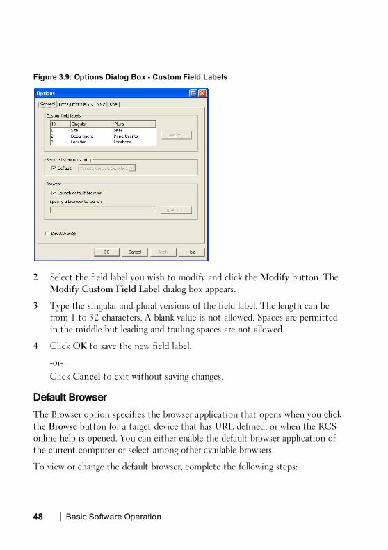
Figure 3.9: Options Dialog Box - Custom Field Labels
2 Select the field label you wish to modify and click theModify button. TheModify Custom Field Label dialog box appears.
3 Type the singular and plural versions of the field label. The length can befrom 1 to 32 characters. A blank value is not allowed. Spaces are permittedin the middle but leading and trailing spaces are not allowed.
4 Click OK to save the new field label.
-or-Click Cancel to exit without saving changes.
Default Browser
The Browser option specifies the browser application that opens when you clickthe Browse button for a target device that has URL defined, or when the RCSonline help is opened. You can either enable the default browser application ofthe current computer or select among other available browsers.
To view or change the default browser, complete the following steps:

Basic Software Operationxxx | xxx49
1 Select Tools - Options from the Explorer menu. The General Optionswindow opens.
2 Complete one of the following steps:
• In the Browser field, select the Launch Default Browser check box tospecify the default browser.
• Clear the Launch Default Browser check box. Click the Browse buttonand select a browser executable on the computer. You can also enter thefull path name of the browser executable.
3 Complete one of the following steps:
• Click another tab to change additional properties.
• If finished, click OK to save the new settings.
• Click Cancel to exit without saving the new settings.
Changing DirectDraw Support (Windows OS Only)
The software supports DirectDraw, a standard that allows direct manipulation ofvideo display memory, hardware overlays, and page flipping without theintervention of the Graphical Device Interface (GDI). This can result insmoother animation and improvement in the performance of display-intensivesoftware.
However, if your machine has a software cursor or pointer shadow enabled, or ifyour video driver does not support DirectDraw, you may experience a flicker inyour mouse cursor when over the title bar of the Viewer.
You can disable the software cursor or pointer shadow, load a new driver for yourvideo card, or you can disable DirectDraw.
To disable DirectDraw:
1 Select Tools - Options from the Explorer menu. The Options dialog boxappears.
2 Click to disable the DirectDraw check box.
3 Click OK.

50xxx | Basic Software Operationxxx
NOTE: The DirectDraw check box will only appear for Windows basedOperating Systems.
HTTP/HTTPS Options
The Remote Console Switch and software use port 80 as the default HTTP portand port 443 as the default HTTPS port. You can change the default portnumbers used in the HTTP/HTTPS Ports tab of the Options dialog box.
1 Select Tools - Options from the Explorer menu. The Options dialog boxappears.
2 Click the HTTP/HTTPS Ports tab.
3 Type the new default HTTP and HTTPS port numbers.
4 Click OK.
VNC Options
The software supports user-defined VNC viewers via the properties page. In theVNC tab you can search for a user-specific VNC application and you mayinclude its command-line arguments. A selection of macros is available forplacement in the command-line; this may be useful for automatic replacementof variables such as IP address, port number, user name, and password. For VNCcommands that do not provide their own GUI, such as those for standardWindows, Linux, and UNIX, you may have the VNC application launch fromwithin an OS command window.
To change VNC options:
1 Select Tools - Options from the Explorer menu. The Options dialog boxappears.
2 Click the VNC tab.
3 In the Application to Launch field, enter the directory path and name orclick the Browse button to locate the path and name.
4 Enter command-line arguments in the box below the path and name.
- or -

Basic Software Operationxxx | xxx51
To insert a predefined macro at the cursor location in the command-line, click the Insert Macro list box and select a macro from the drop-down menu. The RCS software will automatically replace these variableswhen the application runs.
5 Enable/disable the Launch in command window check box. When enabled,the user-specified VNC application will be launched from within an OScommand window.
6 Click OK.
RDP Options
The software supports user-defined RDP viewers via the properties page. In theRDP tab you can search for a user-specific RDP application and you mayinclude its command-line arguments. A selection of macros is available forplacement in the command-line; this may be useful for automatic replacementof variables such as IP address, port number, user name, and password. For RDPcommands that do not provide their own GUI, such as those for standardWindows, Linux, and UNIX, you may have the RDP application launch fromwithin an OS command window.
To change RDP options:
1 Explorer menu. The Options dialog box appears.
2 Click the RDP tab.
3 In the Application to Launch field, enter the directory path and name orclick the Browse button to locate the path and name.
4 Enter command-line arguments in the box below the path and name.
- or -To insert a predefined macro at the cursor location in the command-line, click the Insert Macro list box and select a macro from the drop-down menu. The RCS software will automatically replace these variableswhen the application runs.

52xxx | Basic Software Operationxxx
5 Enable/disable the Launch in command window check box. When enabled,the user-specified RDP application will be launched from within an OScommand window.
6 Click OK.
Organizing Your SystemThe Sites and Folders view tabs in the RCS software allow you to organize andmanage your Remote Console Switches and servers by custom groups. Siteorganization is based on where your servers are located and refers to the columnheadings Site and Department, which can be customized to suit your needs. See"Modifying Custom Field Names" on page 53. Folders are a way to create acustomized organizational system for individual servers. For example, you mightwant to create a folder for critical servers or for remote servers.
You may change the order and sorting of the Unit Selector list by clicking in thecolumn header. An upward-pointing arrow in a column header indicates that thelist is sorted by that field name in ascending order. A downward-pointing arrowindicates the list is sorted by that field name in descending order.
You can customize the column headings. Figure 3.10 shows an example of howyou might use the default field name values. You may change them to fit yourown organization. Figure 3.11 shows an example of customized field names.

Basic Software Operationxxx | xxx53
Figure 3.10: Sites View Tab Selected
Modifying Custom Field Names
Custom field names allow you to change the Site, Department, and Locationcolumn heading names that appear in the Group and Unit Selector panes in thesoftware. This allows you to group Remote Console Switches and servers in waysthat are meaningful to you. The Department field is a subset of Site. If youcustomize these field names, you should keep this hierarchy in mind.
Figure 3.11: Example of Modified Custom Fields

54xxx | Basic Software Operationxxx
To create a new site, department, or location:
1 Select View - Properties from the Explorer menu.
-or-Click the Properties task button. The Properties dialog box appears.
2 Click the General tab and select the drop-down list for Site, Department,or Location. If a name is not in the drop-down list, type the name you wantin the text field. The name can be from 1 to 32 characters long. Names arenot case sensitive and can consist of any combination of characters enteredfrom the keyboard. Spaces are permitted in the middle but leading andtrailing spaces are not allowed. Duplicate names are not allowed.
3 Click OK. The new site, department, or location appears in the GroupSelector pane.
Creating Folders
To create a new folder:
1 Select the Folders View Selector tab.
2 Click the Folders node and select File - New - Folder.
-or-Right-click the Folders node and select New Folder. The New Folderdialog box appears.
3 Type a name for the folder from 1 to 32 characters long. Folder names arenot case sensitive and can consist of any combination of characters enteredfrom the keyboard. Spaces are permitted in the middle but leading andtrailing spaces are not allowed. Duplicate folder names are not allowed atthe same level but are allowed across different levels.
4 Click OK. The new folder appears in the Group Selector pane.

Basic Software Operationxxx | xxx55
Assigning a Unit to a Site, Location, or Folder
You can assign a Remote Console Switch or server to a Site, Department,Location or Folder in the software. This menu item is only enabled when asingle Remote Console Switch or server is selected in the Unit Selector pane.These custom targets are defined in the General Properties dialog box.
To assign a unit to a site, location, or folder:
1 Select a unit in the Unit Selector pane.
2 Select Edit - Assign from the Explorer menu.
-or-Click the Assign To task button.-or-Right-click a unit and select Assign To. The Assign To dialog boxappears.
3 Select the site, location, or folder category from the drop-down list.
4 Select the target from the list of available targets to which the unit can beassigned within the chosen category. This could be empty if no site,location, or folder has been defined in the local database.
5 Click OK to save the assignment.
-or-Click Cancel to exit without saving changes.
To drag and drop a unit into a site, department, location, or folder:
1 Click and hold on a unit in the Unit list in the software.
2 Drag the item to the node in the tree view of the Group Selector pane.
3 Release the mouse button. The item now appears in the Unit list when youclick that node.
NOTE: A unit cannot be moved to All Departments, All Units, or the root Sitesnode. Units can only be moved one at a time.

56xxx | Basic Software Operationxxx
Deleting and Renaming
The delete function is context-sensitive based on what is currently selected inthe Group and Unit Selector panes in the software. When you select and deletea unit in the Unit list, the unit is removed from the local database. When youselect and delete an item in the tree view of the Group Selector pane, you willdelete Server Types, Sites, Departments, and Folders. However, none of theactions result in units being deleted from the local database.
The rename function is also context-sensitive. You can select and rename aRemote Console Switch or a server from the Unit list. You can select andrename server types, sites, departments, and folder names in the tree view of theGroup Selector pane.
To delete a Remote Console Switch or server:
1 Select the unit(s) you wish to delete from the Unit Selector pane.
2 Select Edit - Delete.
-or-Press the <Del> key on your keyboard. A dialog box appearsconfirming the number of units to be deleted. If you are deleting aRemote Console Switch, the dialog box includes a Delete AssociatedServers check box. Click to enable/disable the check box as desired.
3 Click Yes to confirm the deletion. Additional message prompts may appeardepending on your configuration. Respond as appropriate. The RemoteConsole Switch or server is deleted.
-or-Click No to cancel.
To delete a server type, site, department, or folder:
1 Select the server type, site, department, or folder you wish to delete fromthe Group Selector pane.
2 Select Edit - Delete.
-or-

Basic Software Operationxxx | xxx57
Press the <Del> key on your keyboard. A dialog box appearsconfirming the number of units that will be affected by this deletion.
3 Click Yes to confirm the deletion. Additional message prompts may appeardepending on your configuration. Respond as appropriate. The element isdeleted.
-or-Click No to cancel.
To rename a unit, site, department, or folder:
1 Select the server type, site, department, or folder you wish to delete fromthe Group Selector pane in the RCS software.
2 Select Edit - Rename. The Rename dialog box appears.
3 Type a name from 1 to 32 characters long. Names are not case sensitive andcan consist of any combination of characters entered from the keyboard.Spaces are permitted in the middle but leading and trailing spaces are notallowed. Duplicate names are not allowed, with two exceptions: departmentnames can be duplicated across different sites and folder names can beduplicated across different levels.
4 Click OK to save the new name.
Customizing the Explorer WindowThe RCS software Explorer window can be resized at any time. Each time youlaunch the application, the Explorer window opens to its default size andlocation. You can manually resize the window while the application is running,but the information is not saved. The next time Explorer is started, it will comeup in its default size and location.
A split-pane divider that runs from top to bottom separates the Group Selectorpane and the Unit Selector pane. You can move the divider left and right tochange the viewing area of the Group Selector pane and the Unit Selector pane.Each time Explorer is started the divider will appear in its default location.

58xxx | Basic Software Operationxxx
Modifying the Selected View on Startup
When Default is checked under the Selected view on startup option, theExplorer will determine which view to display. If you have one or more serversdefined, the Servers tab will appear by default. If you do not, the RemoteConsole Switches tab will appear.
When Default is unchecked, the Explorer will display the view selected in thedrop-down list shown below the check box. The drop-down list contains thefollowing values: Remote Console Switches, Servers, Sites, and Folders. Thedrop-down list is only enabled when the check box is disabled.
To modify the selected view on startup:
1 Select Tools - Options from the Explorer menu in the RCS software. TheOptions dialog box appears.
2 Select Remote Console Switches, Servers, Sites, or Folders from the drop-down list.
3 Click OK to save the new startup view.
-or-Click Cancel to exit without saving changes.
Changing the Default Browser
You can specify which browser launches when viewing a server URL in a browserwindow. You have the option of using the default browser for your system, oryou can select a specific browser to launch for that server.
To change the default browser:
1 Select Tools - Options from the Explorer menu. The Options dialog boxappears.
2 Click to disable the Launch Default Browser check box. The Browsebutton is enabled.
3 Click the Browse button and navigate to the browser.
4 Click OK to save the new browser selection.

Basic Software Operationxxx | xxx59
-or-Click Cancel to exit without saving changes.
Managing Your Local DatabasesEach client workstation running the software contains a local database thatrecords the information that you enter about your units. If you have multipleclient workstations, you may wish to configure one station and then save a copyof this database and load it into the other stations to avoid having toreconfigure each station. You might also wish to export the database for use inanother application.
Saving a Database
The RCS software allows you to save a copy of the local database. The saveddatabase can then be loaded back to the same computer where it was created, orit can be loaded onto another client workstation. The saved database iscompressed into a single Zip file.
While the database is being saved, no other activity is allowed, and all otherwindows must be closed. If other windows are open, a message will appearprompting you to either continue and close all open windows or quit and cancelthe database save process.
To save a database:
1 Select File - Database - Save from the RCS Explorer menu. The DatabaseSave dialog box appears.
2 Select a database to save.
3 Type a file name and browse to a location to save the file.
4 Click Save. A progress bar appears during the save. When finished, amessage appears indicating that the save was successful and you are returnedto the main window.

60xxx | Basic Software Operationxxx
Loading a Database
This function allows you to load a database that was previously saved. No otheractivity is allowed, and all other windows must be closed. If other windows areopen, a message appears prompting you to either continue and close all openwindows or quit and cancel the database save process.
To load a database:
1 Select File - Database - Load from the Explorer menu. The Database Loaddialog box appears.
2 Browse to select the database you wish to load.
3 Click Load. A progress bar appears during the load. When finished, amessage appears indicating that the load was successful and you are returnedto the main window.
Exporting a Database
This function allows you to export fields from the local database to an ASCIIComma Separated Value file (CSV) or Tab Separated Value file (TSV). Thefollowing database fields will be exported.
Remote Console Switch Flag
Type
Name
Address
Site
Department
Location
Description
Contact Name
Contact Phone #
Comments

Basic Software Operationxxx | xxx61
Browser URL
Telnet Port
NOTE: The Address field only applies to Remote Console Switches and theBrowser URL field only applies to servers. In the exported file, the Addressfield data will be empty for servers and the Browser URL field data will beempty for Remote Console Switches.
The first line of the exported file contains the column names for the field data.Each additional line contains the field data for a Remote Console Switch orserver. The file will contain one line for each Remote Console Switch and serverdefined in the local database.
To export a database:
1 Select File - Database - Export from the Explorer menu. The DatabaseExport dialog box appears.
2 Type a file name and navigate to the location where you wish to save theexported file.
3 Select the type of export format you wish from the Files of Type drop-downlist.
4 Click Export. A progress bar appears during the export. When finished, amessage appears indicating that the export was successful and you arereturned to the main window.

62xxx | Basic Software Operationxxx
4
Using the Viewerxxx | xxx63
Using the Viewer
You can connect to a server in the Remote Console Switch system using theViewer. The Viewer allows you full keyboard, monitor, and mouse control over aserver. You can also scan through a customized list of servers by enablingindividual servers to appear in the Thumbnail Viewer. This view contains aseries of thumbnail frames, each containing a small, scaled, non-interactiveversion of a server's screen image. For more information, see "Viewing MultipleServers Using the Scan Mode" on page 79.
Accessing Servers from the RCS SoftwareThe Servers tab in the RCS software displays a list of servers defined in thedatabase. The Group Selector pane appears displaying a tree view containing allof the unique server types that are defined in the database. The Group Selectorpane only appears if two or more server types are defined. You can either clickAll Servers or click on a folder to view all the servers of a particular type. Whenyou select a server and click the Connect Video task button, the Viewerlaunches.

64xxx | Using the Viewerxxx
Figure 4.1: RCS Software - Servers Tab
To access a server:
1 Click the Servers tab in the Explorer.
2 Select a server in the Unit Selector pane.
3 Click the Connect Video task button.
-or-Right-click on the server. A pop-up menu appears. Select ConnectVideo.-or-Double-click the server name.-or-Press <Enter>. The Viewer launches in a new window.
To search for a server in the system:
1 Click the Servers tab and insert your cursor in the search text box.

Using the Viewerxxx | xxx65
2 Type the search information. This can be the server name or anyinformation you have entered in the other Unit Selector list headings suchas Type or Location.
3 Click the Search button. The results appear in the Unit list.
4 Review the results of your search.
-or-Click the Clear Results button to display the entire list again.
Interacting With the Server Being ViewedOnce you have connected to a server, you will see the desktop window of theserver on your screen. This opens in a separate window. You will see two cursors,the local cursor and the server’s cursor. You may need to align these if they donot move together or adjust the video if they seem to jump about. From thiswindow, you will be able to access all the normal functions of this server as ifyou were sitting right in front of it. You may also perform Viewer-specific taskssuch as sending special macro commands to the server.
NOTE: If you are experiencing slow mouse response during a remote videosession, deactivate mouse acceleration in the operating system of the targetdevice and set mouse speed to 50%.

66xxx | Using the Viewerxxx
Viewer Window FeaturesFigure 4.2: Viewer Window
1 Menu bar: Access many of the features in the Viewer.
2 Accessed server desktop: Interact with your server through this window.

Using the Viewerxxx | xxx67
Viewer Menu Bar
Figure 4.3: Viewer Menu Bar
1 Thumbtack: Click to lock the menu bar in place. This prevents the menubar from hiding once you have moved the mouse cursor away from themenu bar.
2 Menu Options: The menus provides access to functions available throughthe Viewer.
3 Toolbar Buttons: You may add up to 10 buttons to the tool bar. Thesebuttons allow you to provide easy access to defined functions and keyboardmacros. By default, the Align Local Cursor, Refresh Image, and Single CursorMode buttons are displayed.
4 Connection Status Indicator: The connection status indicator indicateshow the user is connected to the appliance for this server. For moreinformation see "Session Sharing Options" on page 87.
Connection Status Indicator Sharing Mode
Exclusive Mode
Active Connection (normal, non-sharing, non-exclusive session)
Table 4.1: Connection Status Indicators

68xxx | Using the Viewerxxx
Connection Status Indicator Sharing Mode
Active Sharing (Primary User)
Active Sharing (Secondary User)
Passive Sharing
Stealth Mode
Scanning
5 Smart Card Status Indicator: The smart card status is indicated by thesmart card icon at the far right side of the Video Viewer toolbar.
Icon Description
A smart card is not in the smart card reader, or a smart card readeris not attached.
A smart card is in the smart card reader but has not been mapped.
A smart card is mapped.
Table 4.2: Smart Card Status Indicators
Adjusting the Viewer
You can adjust the Viewer settings to match your requirements. This includesadjustment of the video resolution, toolbar settings, and keyboard macrosettings.

Using the Viewerxxx | xxx69
Adjusting the Viewer Toolbar
You may add up to 10 buttons to the toolbar. These buttons allow you toprovide easy access to defined function and keyboard macros. By default, theAlign Local Cursor, Refresh Image, and Single Cursor Mode buttons aredisplayed.
To add buttons to the toolbar:
1 From the Tools menu in the Viewer, choose Session Options. The SessionOptions toolbar is displayed.
2 Click the Toolbar tab.
3 Click to select the items you want to add to the Viewer toolbar.
4 Click OK to accept the changes and return to the Viewer main window.
Figure 4.4: Session Options Dialog Box - Toolbar Tab
Setting the Toolbar Hide Delay Time
Unless the Thumbtack button has been clicked, the toolbar will disappear whenyou remove the mouse cursor. You can change the interval between the removal
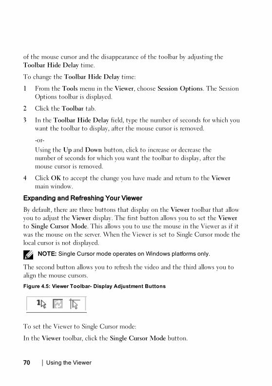
70xxx | Using the Viewerxxx
of the mouse cursor and the disappearance of the toolbar by adjusting theToolbar Hide Delay time.
To change the Toolbar Hide Delay time:
1 From the Tools menu in the Viewer, choose Session Options. The SessionOptions toolbar is displayed.
2 Click the Toolbar tab.
3 In the Toolbar Hide Delay field, type the number of seconds for which youwant the toolbar to display, after the mouse cursor is removed.
-or-Using the Up and Down button, click to increase or decrease thenumber of seconds for which you want the toolbar to display, after themouse cursor is removed.
4 Click OK to accept the change you have made and return to the Viewermain window.
Expanding and Refreshing Your Viewer
By default, there are three buttons that display on the Viewer toolbar that allowyou to adjust the Viewer display. The first button allows you to set the Viewerto Single Cursor Mode. This allows you to use the mouse in the Viewer as if itwas the mouse on the server. When the Viewer is set to Single Cursor mode thelocal cursor is not displayed.
NOTE: Single Cursor mode operates on Windows platforms only.
The second button allows you to refresh the video and the third allows you toalign the mouse cursors.
Figure 4.5: Viewer Toolbar- Display Adjustment Buttons
To set the Viewer to Single Cursor mode:
In the Viewer toolbar, click the Single Cursor Mode button.

Using the Viewerxxx | xxx71
To refresh the screen:
Click the Refresh Image button on the Viewer toolbar.
-or-
From the Viewer menu, select View - Refresh. The digitized video image will becompletely regenerated.
To align the mouse cursors:
Click the Align Local Cursor button on the Viewer toolbar. The local cursor willalign with the cursor on the remote server.
To enter full screen mode:
Click theMaximize button in the top right-hand corner of the Viewer.
-or-
From the Viewer menu, select View - Full Screen. The desktop window willdisappear and only the accessed server desktop will be visible. The screen will beresized up to a maximum of 1600 x 1200 (standard) and 1680 x 1050(widescreen). If the desktop has a higher resolution, then a black background willsurround the full screen image. The floating toolbar will appear.
To exit full screen mode:
Press <Esc> to exit full screen mode and return to the desktop window.
Adjusting the Viewer Resolution
If Auto Scale is enabled, the display automatically adjusts when the Viewerwindow size changes during a session. When you access a channel using sharing,the display adjusts to match the input resolution selected by the primary user ofthat channel. This prevents the primary user's display from being affected. If theresolution changes any time during a session, the display is adjustedautomatically.
When Full Scale is selected, the Viewer adjusts to the screen resolution of theserver and sets the screen size accordingly, up to a maximum resolution of 1600x 1200 (standard) and 1680 x 1050 (widescreen).

72xxx | Using the Viewerxxx
To adjust the size of the Viewer window:
From the menu bar, select View - Scaling - Auto Scale to allow the server imageto be scaled automatically.
-or-
From the menu bar, select View - Scaling - Full Scale
-or-
Select a screen resolution from the Scaling sub-menu.
Figure 4.6: Viewer Scaling
Adjusting the Video Quality
The Viewer offers both automatic and manual video adjustment capability.Generally, the Automatic Video Adjustment will optimize the video for the bestpossible view. However, you may wish to alter the video for your specific needs.Use the slider bar for large adjustments. The Plus (+) andMinus (-) buttons aredesigned for fine-tuning adjustments. For more information on manual videoadjustment, please see Figure 4.7.

Using the Viewerxxx | xxx73
Adjusting Color Depth
NOTE: The Color command may only be used by the primary user. Thecommand is not available to non-primary users who are sharing the session.
NOTE: If Background Refresh is enabled from the Session Options dialog,the color depth will be set automatically to Best Color Available and cannotbe changed.
The Color sub-menu allows you to set the color depths at which the digitalimage can be compressed. The Remote Console Switches support theDambrackas Video Compression (DVC) algorithm, which enables the RCSsoftware users to adjust the number of viewable colors in a remote sessionwindow. You may choose to display more colors for the best fidelity, or fewercolors to reduce the volume of data transferred on the network.
The Viewer window can be viewed using the Best Color Available (slowerupdates), Best Compression (fastest updates), a combination of Best Color andBest Compression, or in Grayscale.
The color depths of individual ports and channels can be specified by selectingthe View - Color command in a Remote Session window. These settings aresaved individually per port and channel.
To set the color depth:
From the View menu, choose Color and select a color depth from the Colorsub-menu.
To manually adjust the video quality of the Viewer window:
1 From the Viewer menu, select Tools - Manual Video Adjust. TheManualVideo Adjust dialog box appears.
2 Click the icon for the feature you wish to adjust.
3 Move the slider bar or click theMinus (-) or Plus (+) buttons to adjust theparameter for each icon pressed. The adjustments will display immediatelyin the Viewer window.
4 When finished, click Close to exit theManual Video Adjust dialog box.

74xxx | Using the Viewerxxx
Manual Video Adjust Dialog Box Options
Figure 4.7: Manual Video Adjust Dialog Box
NOTE: If you use theon-board web interface to launch the Viewer, theManual Video Adjust dialogbox will appear as shown above. If you use theRCS softwareto launch the Viewer, there will also be a Help button above theClose button.
1 Image Capture Width
2 Pixel Sampling Fine Adjust
3 Image Capture Horizontal Position
4 Image Capture Vertical Position
5 Contrast

Using the Viewerxxx | xxx75
6 Brightness
7 Noise Threshold
8 Priority Threshold
9 Automatic Video Adjustment
10 Refresh Image
11 Adjustment bar
12 Video Test Pattern
13 Help
14 Performance Monitor
15 Close box
Minimizing Remote Video Session Discoloration
When establishing remote video sessions, pixel discolorations may occur due tonetwork conditions. This condition occurs most often with a solid colorbackground. This condition is minimized by using a black background. If a colorbackground is used, a small number of pixels on the screen will be discolored orwhite.
To minimize remote video pixel discoloration:
1 From the Viewer menu, select Tools - Manual Video Adjust. TheManualVideo Adjust dialog box appears.
2 Choose contrast or brightness.
3 Incrementally, adjust the contrast and brightness until the image qualityimproves.
4 A noise threshold setting is also available under Tools - Manual VideoAdjust for fine incremental adjustments.

76xxx | Using the Viewerxxx
NOTE: Reducing the noise threshold to zero causes constant video refresh,high network usage, and a flickering video. Dell recommends that the noisethreshold be set to the highest level that allows efficient system performance,while still being able to recover pixel colors over which the mouse cursortravels.
NOTE: When adjusting the noise threshold, use the slider bar for largeadjustments and the Plus (+) and Minus (-) buttons at the ends of the sliderbar for fine-tuning.
Improving Screen Background Color Display
You may experience inconsistent color display when viewing target servers wherephotographic images or color-intense gradient backgrounds have been selected.We recommend that you select a solid color display background via theoperating system for optimal display quality and performance.
Adjusting the Mouse
The Viewer allows you to select between five different mouse cursor options, setup mouse scaling, and resynchronize your mouse should it no longer trackproperly. Dell recommends turning off the local cursor by setting the LocalCursor option to None. This will leave only one cursor on the screen, theremote cursor, and will simplify navigation.

Using the Viewerxxx | xxx77
Figure 4.8: Viewer Mouse Session Options dialog box
Setting Mouse Scaling
You can choose between three preset mouse scaling options or set your owncustom scaling. The three preset settings are: Default (1:1), High (2:1), or Low(1:2). In a 1:1 scaling ratio, every mouse movement on the desktop window willsend an equivalent mouse movement to the server. In a 2:1 scaling, the samemouse movement will send a 2X mouse movement. In a 1:2 scaling, the valuewill be 1/2X.
To set custom mouse scaling:
1 From the Viewer menu, select Tools - Session Options. The SessionOptions dialog box appears.
2 Click theMouse tab.
3 Click the Custom radio button. The X and Y fields become enabled.
4 Type the mouse scaling values you wish in the X and Y fields. For everymouse input, the mouse movements are multiplied by the respective X andY scaling factors. Valid input ranges are 0.25 to 3.00.

78xxx | Using the Viewerxxx
Minimizing Mouse Trailing
During a remote video session, as the mouse moves on the screen, some pixelswill remain discolored. This condition is referred to as mouse trailing, and is dueto varying levels of network and other noise in different environments. Tominimize mouse trailing, you may need to reduce the Noise Threshold in theManual Video Adjust dialog box.
To reduce the Noise Threshold:
1 From the Viewer menu, select Tools - Manual Video Adjust. TheManualVideo Adjust dialog box appears.
2 Click the Noise Adjust Threshold icon for the feature you wish to adjust.
3 Using the mouse, move the slider bar to the center of the scale, and thendown to zero.
4 Use the Plus (+) andMinus (-) buttons at the end of the slider bar to fine-adjust the noise threshold to just above zero.
NOTE: Leaving the noise threshold at zero triggers constant video refresh,resulting in high network usage and a flickering video. It is recommended thatthe noise threshold be set at the highest level that allows efficient systemperformance, while still being able to recover pixel colors that the mousecursor travels over.
NOTE: When adjusting the noise threshold, the slider bar is used for largeadjustments and the Plus (+) and Minus (-) buttons at either end of the sliderbar for fine-tuning.
Improving Mouse Performance
If you are experiencing slow mouse response or if the mouse pointers get out ofsync during a remote video session, you may want to deactivate the mouseacceleration in the operating system of the target server.
Microsoft Windows:
1 Turn off mouse acceleration
2 Adjust mouse speed to the exact midpoint of the slider bar.

Using the Viewerxxx | xxx79
NOTE: See the documentation included with your Windows operating systemfor specific instructions.
Red Hat Linux:
1 Select theMouse settings from the Desktop Controls.
2 Set Acceleration to 1.0.
3 Apply the changes and use the Align Local Cursor/Mouse button in theViewer to resynchronize the mouse.
Reducing Mouse Cursor Flickering
If the video driver on the RCS software client machine does not supportDirectDraw® and the DirectDraw option in the RCS software has beenactivated, the mouse cursor will flicker on the screen. The RCS software factorydefault has DirectDraw disabled. If the video driver on the client systemsupports DirectDraw and the additional performance is desired, follow theinstructions below to enable DirectDraw.
To enable or disable DirectDraw:
1 In the Explorer window, select Tools - Options.
2 Click to enable or disable the DirectDraw check box.
3 Click OK.
4 Restart the RCS software.
Viewing Multiple Servers Using the Scan Mode
The Viewer allows you to simultaneously view multiple servers through theThumbnail Viewer of the Scan mode. This view contains a series of thumbnailframes, each containing a small, scaled, non-interactive version of a server'sscreen image. The server name displays below each thumbnail as well as thestatus indicator.

80xxx | Using the Viewerxxx
Scanning Your Servers
Using the Thumbnail Viewer, you can set up a scan sequence of up to 16 serversto monitor your servers. The scan mode moves from one thumbnail image to thenext, logging into a server and displaying an updated server image for a user-specified length of time (View Time Per Server), before logging out of thatserver and moving on to the next thumbnail image. You can also specify a scandelay between thumbnails (Time Between Servers). During the delay, you willsee the last thumbnail image for all servers in the scan sequence, though youwon't be logged into any servers.
An indicator light at the bottom of each frame displays the status of the server.The default thumbnail size is based on the number of servers in the scan list.
Figure 4.9: Viewer - Thumbnail Viewer
Scan mode is a lower priority than an active connection. If you have aninteractive session with a server, that server will be skipped in the scan sequenceand the scan mode will proceed to the next server. No login error messages willappear. Once the interactive session is closed, then the thumbnail will beincluded in the scan sequence again. If another user has an active connection to

Using the Viewerxxx | xxx81
a server, the server will be skipped and a red “X” will be displayed in theindicator light below the frame.
The RCS software can scan connected servers on multiple Remote ConsoleSwitches.
Accessing Scan Mode from the RCS Software
Figure 4.10: RCS Software- Scanning Servers
To access the Scan mode in the RCS software:
1 In the Explorer, select the Remote Console Switches, Servers, Sites, orFolders tab.
2 Select two or more servers in the Unit Selector pane by pressing the<Shift> key.
-or-Press the <Ctrl> key. The Scan Mode task button appears.
3 Click the Scan Mode task button. The Thumbnail Viewer window appears.

82xxx | Using the Viewerxxx
Thumbnail View Status Indicators
The green LED indicates that a server is currently being scanned. The red Xindicates that the last scan of the server was not successful. The scan may havefailed due to a credential or path failure (the server path on the Remote ConsoleSwitch was not available), or because of some other reason. When the mousepointer is placed on the red X a tool tip appears and indicates the reason for thefailure. Setting up your Scanning Preferences
To set scan preferences:
1 From the Thumbnail Viewer, select Options - Preferences. The Preferencesdialog box appears.
2 Enter the time each thumbnail will be active during the scan (10 to 60seconds) in the View Time Per Server box.
3 Enter the length of time the scan stops between each server (5 to 60seconds) in the Time Between Servers box.
4 Click OK.
Navigating the Thumbnail Viewer
When you highlight an individual thumbnail frame and select the Thumbnailmenu, you can launch an interactive session to that server, add that server to thescan sequence or set the login credentials for that server. The Options menuallows you to access scanning preferences as well as pause the scan and set thethumbnail size for all servers.
To launch a server Video session:
1 Select a server thumbnail.
2 From the Thumbnail Viewer, select Thumbnail - [server name] - ViewInteractive Session.
-or-Right-click a server thumbnail and select View Interactive Session.That server's video will be launched in an interactive Viewer window.

Using the Viewerxxx | xxx83
To enable or disable a server in the scan sequence:
1 Select a server thumbnail.
2 From the Thumbnail Viewer, select Thumbnail - [server name] - Enable.
-or-Right-click a server thumbnail and select Enable. That server will beincluded/excluded in the server thumbnail scan sequence.NOTE: The Enable menu item state can be toggled from checked (enabled)to unchecked (disabled) each time it is selected.
NOTE: If a server is being accessed by a user, the Enable menu will bedisabled for that server thumbnail.
To pause or restart a scan sequence:
From the Thumbnail Viewer, select Options - Pause Scan. The scan sequencewill pause at the current thumbnail if the Thumbnail Viewer has a scan inprogress or will restart the scan if currently paused.
To change the thumbnail size:
1 From the Thumbnail Viewer, select Options - Thumbnail Size.
2 Select the desired thumbnail size from the menu.
Using Macros to Send Keystrokes to the Server
The Macros menu in the Viewer allows you an easy way to send multiplekeystrokes to the server. The Viewer provides a list of available keystrokeselections for Microsoft Windows, Sun, and Linux systems.
To choose which system you are using:
Click theMacro menu in the Viewer. Select Display on Menu, and select eitherWindows, Sun, or Linux.
To send keystrokes to the server:
Click theMacro menu in the Viewer and choose the name of the macrocontaining the keystrokes you wish to send to the server. Figure 4.11, Figure4.12, and Figure 4.13 show the available macros.

84xxx | Using the Viewerxxx
Figure 4.11: Viewer Macro Menu Expanded - Windows Option
Figure 4.12: Viewer Macro Menu Expanded - Sun Option

Using the Viewerxxx | xxx85
Figure 4.13: Viewer Macro Menu Expanded - Linux Option
Session Options - General Tab
The General tab in the Session Options dialog box allows you to control theKeyboard Passthrough option in non-full screen mode, theMenu ActivationKeystroke, and the Background Refresh selection.
The Keyboard Pass-through check box allows you to specify whether KeyboardPass-through mode is enabled, or not. The Keyboard Pass-through option is notselected by default.

86xxx | Using the Viewerxxx
Figure 4.14: Session Options - General Tab
TheMenu Activation Keystroke list (None, Pause, and F1-F12) allows you toselect a keystroke that activates the toolbar.
The Background Refresh check box allows you to specify whether backgroundrefreshing occurs. When this option is selected the Viewer is sent a constantstream of data from the device whether or not a change has occurred on thedevice.
To change session options:
1 From the Tools menu in the Viewer, choose Session Options. The SessionOptions toolbar is displayed.
2 Click the General tab.
3 Modify the session options as desired.
4 Click OK.
Screen Capturing
The Viewer allows you to capture the contents of the screen and to save it to afile or to copy it to the clipboard.

Using the Viewerxxx | xxx87
To capture a screen as a file:
1 In the Viewer, choose File - Capture to File. The Save dialog is displayed.
2 Browse to the location where you want to save the file.
3 In the File Name field, type a file name and click Save.
To copy a screen to the clipboard:
In the Viewer, choose File - Capture to Clipboard. The image is saved to theclipboard and can be pasted into a document or image editing application.
NOTE: The Capture to Clipboard function is not available in Linux.
Session Sharing Options
NOTE: For Dell 1081AD and 2161AD switches the optional Dell RemoteAccess Key is required to support session sharing.
Session sharing can be configured by Admin and other users with ApplianceAdministrator or User Administrator rights. The first user with a KVM sessionwith a target device is called the primary user. If another (secondary) userattempts to start a KVM session with the same target device, options for thesecondary user depend on the following two conditions:
• The access rights of the two users
• Whether an administrator has configured global connection sharing
Automatic Sharing, Exclusive Connections, and Stealth Connections all areconfigurable options that require connection sharing to be enabled.
Automatic Sharing
Connection sharing allows multiple users to interact with a target device at thesame time. When you are a primary user, you may be notified by a dialog boxthat another user would like to share your connection. You may select Yes to

88xxx | Using the Viewerxxx
accept sharing, No to reject sharing, or click the Passive Share box to allow thenew user to share without having any control over the connection.
When you attempt to open a Video session with a device that is already beingviewed by another user, you are notified that the device is already being viewed.Depending on the configuration of sharing settings, you may be offered theoption to share or preempt the video session. You may also be offered theoption to open a stealth Video session.
Access to the device is governed by the nature of the current user’s connectionto the device. There are two types of Video session users: a Primary user and upto 11 simultaneous Secondary users. Only the Primary user can accept or rejectpreemption requests for all users sharing a connection. The Primary user alsomaintains control of video parameters and the display resolution of the Videosession.
Secondary users may be either Active users who have the ability to input mouseand keyboard data, or Passive users who may not input mouse and keyboarddata.
If Automatic Sharing is enabled on the Remote Console Switch, SecondaryUsers do not need the permission of the Primary User to join the session.
If a Primary user leaves the session, then the oldest Secondary user with Activeuser privileges will become the Primary user. If there are no Secondary users withActive user privileges sharing the session when the Primary user leaves thesession, then the session will be closed.
Multiple users can view and interact with a target device using digital sharemode. When a session is shared, the secondary user can be an active user withkeyboard and mouse control or a passive user that does not have keyboard andmouse control.
To configure a switch to share KVM sessions, complete the following steps:
1 Click the Appliances button in the Explorer.
2 Complete one of the following steps:
• Double-click on a Remote Console Switch in the Unit list.

Using the Viewerxxx | xxx89
• Select a Remote Console Switch from the Unit list, then click theManage Appliance button.
• Right-click on a Remote Console Switch in the Unit list. SelectManage Appliance from the pop-up menu.
• Select a Remote Console Switch in the Unit list and press Enter.
3 Select the Global - Sessions subcategory.
4 Select Enable Share Mode in the Connection Sharing area.
5 You can choose to select Automatic Sharing. This enables secondary usersto automatically share a KVM session without first requesting permissionfrom the primary user.
To share a digital connection, complete the following steps:
1 Click the Devices button in the Explorer.
2 Complete one of the following steps:
• Double-click on the target device in the Unit list.
• Select the target device, then click the Connect Video button.
• Right-click on the target device. Select Connect Video from the pop-upmenu.
• Select the target device and press Enter.
When another user is viewing this target device, a message indicatesthat the target device is already involved in a KVM session.If connection sharing is enabled on the switch and your access rights (ascompared with those of the primary user) allow it, you are prompted toeither share or preempt the existing session.
1 If the option is available, select Share.
2 Complete one of the following steps:

90xxx | Using the Viewerxxx
• Click OK or Yes. If Automatic Sharing is not enabled, a share request issent to the primary user, who can accept the share request as either anactive or passive (read-only) session, or reject the share request entirely.
• Click No to cancel the share request.
If the primary user accepts the share request, or if Automatic Sharing is enabled,a KVM session to the target device session opens, and the session type iconwithin the new Video Viewer window indicates if the session status is active orpassive. If the request is rejected, a message indicates that the request wasdenied. Administrators have several options at this point. They can either try toconnect again and preempt the session or connect in stealth mode, or they canterminate the session entirely.
If you are not prompted to connect in share mode, either the switch to whichthe target device is connected is not configured to allow digital share modesessions or it is not a Remote Console Switch.
Exclusive Mode
If session sharing and exclusive connections are enabled, you can create anexclusive KVM session. When operating a session in exclusive mode, you cannotreceive any share requests from other users. However, administrators can chooseto preempt (or terminate) the session or monitor the session in stealth mode.
If other users are sharing the session when you select Exclusive Mode, you arewarned that selecting Exclusive Mode will cause the other users to becomedisconnected from the session.
NOTE: Only the Primary user can request an Exclusive session. If other usersare sharing at the time Exclusive Mode is requested, they are disconnected,regardless of the Primary users access level.
To enable exclusive KVM sessions on a switch, complete the following steps:
1 Click the Appliances button in the Explorer.
2 Complete one of the following steps:
• Double-click on a Remote Console Switch in the Unit list.

Using the Viewerxxx | xxx91
• Select a Remote Console Switch from the Unit list, then click theManage Appliance button.
• Right-click on a Remote Console Switch in the Unit list. SelectManage Appliance from the pop-up menu.
• Select a Remote Console Switch in the Unit list and press Enter.
1 Select the Global - Sessions subcategory.
2 Select the Enable Shared Sessions check box in the Connection Sharingarea.
3 Select Exclusive Connections in the Connection Sharing area.
Only the primary user of a shared connection or the only user of a non-sharedsession can access the Video Viewer in exclusive mode.
To access the Video Viewer in exclusive mode, complete the following steps:
1 Open a KVM session to a target device.
2 Select Tools - Exclusive Mode from the Video Viewer toolbar.
3 If the KVM session is currently shared, only the primary user can designatethe session as exclusive. A message warns the primary user that secondarysessions will be terminated if an exclusive session is invoked.
Complete one of the following steps:
• Select Yes to terminate the sessions of the secondary users.
• Select No to cancel the exclusive mode action.
Secondary users cannot share the exclusive KVM session. However,administrators or users with certain access rights can still terminate the session.
Stealth Connection
Administrators can connect to a target device in stealth mode to view the videooutput of a remote user undetected. When in stealth mode, the administratordoes not have keyboard or mouse control over the target device.
To enable stealth KVM sessions on a switch, complete the following steps:

92xxx | Using the Viewerxxx
1 Click the Appliances button in the Explorer.
2 Complete one of the following steps:
• Double-click on a Remote Console Switch in the Unit list.
• Select a Remote Console Switch from the Unit list, then click theManage Appliance button.
• Right-click on a Remote Console Switch in the Unit list. SelectManage Appliance from the pop-up menu.
• Select a Remote Console Switch in the Unit list and press Enter.
3 Select the Global - Sessions subcategory.
4 Select Stealth Connections in the Connection Sharing area.
To monitor a target device in stealth mode, complete the following steps:
1 Click the Devices button in the Explorer.
2 Complete one of the following steps:
• Double-click on the target device in the Unit list.
• Select the target device, then click the Connect Video button.
• Right-click on the target device. Select Connect Video from the pop-upmenu.
• Select the target device and press Enter.
3 If another user is already viewing this target device, a message indicates thatthe target device is already involved in a KVM session.
If connection sharing and stealth connections are enabled on the switchand your access rights (as compared with those of the primary user)allow it, you are prompted to either share or preempt the existingsession. If the option is available, select Stealth.
4 Complete one of the following steps:
• Click OK or Yes.
• Click No to cancel the stealth request.

Using the Viewerxxx | xxx93
A KVM session to the target device opens, and the administrator canview all video output of the target device while remaining undetected.
If Stealth is not listed as an option, one of the following conditions exist:
• the switch to which the target device is connected is not configured toallow Stealth Connections
• you do not have the necessary access rights (Stealth permissions followPreemption permissions)
• the switch the target device is connected to is not a Remote ConsoleSwitch
Preemption Mode
Preemption provides a means for users with sufficient privilege to take control ofa server from another user with lesser or equal privilege.
NOTE: All users sharing the connection that is being preempted will bewarned, but only the primary user will be able to reject the preemption (ifallowed).
Table 4-3 outlines the preemption scenarios and detailed scenarios in whichpreemption requests can be rejected. For information about preemption andreserved or locked virtual media sessions, see "Session Sharing Options" on page87.
Current User Preempted byPreemption can berejected
Remote User Local User No
Remote User Remote Administrator No
Remote UserRemote Console SwitchAdministrator
No
Table 4.3: Preemption Scenarios

94xxx | Using the Viewerxxx
Current User Preempted byPreemption can berejected
Remote ConsoleSwitch Administrator
Local User Yes
Remote ConsoleSwitch Administrator
Remote Console SwitchAdministrator
Yes
Remote Administrator Local User No
Remote Administrator Remote Administrator Yes
Remote AdministratorRemote Console SwitchAdministrator
No
Local User Remote Administrator Yes
Local UserRemote Console SwitchAdministrator
Yes
Preemption of a Remote User by a Remote Administrator
If a remote administrator attempts to access a server that is being accessed by aremote user, a message appears asking that the administrator wait while the useris informed that they will be preempted. The remote user cannot reject thepreemption request and will be disconnected. The time period given beforedisconnection is defined by the Video session preemption timeout setting inthe Session dialog box.
NOTE: No time period will be displayed in cases where the server beingviewed is attached to an Avocent switch.
Preemption of a Local User/Remote Administrator by a RemoteAdministrator
If an administrator attempts to access a server that is being accessed by thelocal user or by another remote administrator with equal privileges, the currently

Using the Viewerxxx | xxx95
connected user can accept or reject the preemption request. A message appearsasking the connected local user or remote administrator whether they want toaccept the preemption request. If the preemption request is rejected a messageappears informing the remote administrator that their request has been rejectedand that they cannot access the server.
NOTE: If the server being viewed is attached to an Avocent switch, the user isnot given the option to accept or reject preemption.
NOTE: In scenarios where a preemption request can be rejected, theSession Preemption Request dialog box will appear. This dialog allows youto accept the preemption request by clicking the Accept button or to reject thepreemption request by clicking the Reject button or by closing the dialog box.
To preempt the current user, complete the following steps:
1 Click the Devices button in the Explorer.
2 Complete one of the following steps:
• Double-click on the target device in the Unit list.
• Select the target device, then click the Connect Video button.
• Right-click on the target device. Select Connect Video from the pop-upmenu.
• Select the target device and press Enter.
When another user is viewing this target device, a message indicatesthat the target device is already involved in a KVM session.If the switch has connection sharing enabled, you are given the optionto share the session. For information about connection sharing, see"Preemption Mode". If your access rights (as compared with those ofthe primary user) allow it, you are prompted to either share or preemptthe existing session.
3 If the option is available, select Preempt.
4 Complete one of the following steps:

96xxx | Using the Viewerxxx
• Click OK or Yes. A preemption notification is sent to the primary user.Depending on your access rights, the primary user might be able toreject the preemption.
• Click No to let the primary user retain the connection.
5 If the preemption completes, the Video Viewer of the target device sessionopens.
Virtual MediaWith virtual media support, a USB media device can be connected directly tothe appliance USB ports and made available to any target device that isconnected to the appliance. The virtual media can also be accessed remotely.Remote media sessions use devices attached directly to the client computer.
Virtual media allows you to view, move, or copy data located on virtual media toand from any server. You can manage remote systems more efficiently byallowing operating system installation, operating system recovery, hard driverecovery or duplication, BIOS updating, and server backup.
Any user operating a KVM session can access any media device that is mappedto that target device. To avoid the security risk of unauthorized user access, youcan lock a virtual media session to a KVM session.
To change the media in a virtual media device, you must first unmap the virtualmedia device. You can then insert the new media and remap the virtual mediadevice. The media will be available in the new virtual media session.
The following are requirements for virtual media support.
• You can have one DVD-ROM drive and one mass storage device mappedconcurrently.
• A CD/DVD-ROM drive, or ISO disk image file is mapped as avirtual DVD drive.
• A diskette drive, diskette image file, USB memory device, or othermedia type is mapped as a virtual mass storage device.

Using the Viewerxxx | xxx97
• To use virtual media on a given server, a Dell USB2 SIP, Dell USB2+CACSIP, Avocent MPUIQ-VMC, DSAVIQ-PS2M, or DSAVIQ-USB2 modulemust be used to connect that server to the KVM.
• A virtual media session cannot be opened to a server that is connected to apassive expansion module.
• The target device must support the types of USB2-compatible media thatyou virtually map. In other words, if the target device does not support aportable USB 2.0 memory device, you cannot map the local device as avirtual media drive on the target device.
• You (or the user group to which you belong) must have permission toestablish virtual media sessions or reserved virtual media sessions to thetarget device.
• A 1082DS will support up to three concurrent virtual media sessions(including local and remote). A 2162DS will support up to four concurrentvirtual media sessions (including local and remote). A 4322DS will supportup to six concurrent virtual media sessions (including local and remote).Only one virtual media session can be active to a target device at one time.
Sharing and Preemption
The KVM and virtual media sessions are separate; therefore, there are manyoptions for sharing, reserving, or preempting sessions.
For example, the KVM and virtual media sessions can be locked together. In thismode, when a KVM session is disconnected, so is the associated virtual mediasession. If the sessions are not locked together, the KVM session can be closedbut the virtual media session remains active.
After a target device has an active virtual media session without an associatedactive KVM session, either the original user (User A) can reconnect or adifferent user (User B) can connect to that channel. You can set an option inthe Virtual Media window (Reserved) that lets only User A access the associatedtarget device with a KVM session.

98xxx | Using the Viewerxxx
If User B has access to that KVM session (the Reserved option is not enabled),User B could control the media that is being used in the virtual media session.In some environments, this might not be desirable.
By using the Reserved option in a tiered environment, only User A can accessthe lower appliance and the KVM channel between the upper appliance andlower appliance is reserved for User A.
Preemption levels offer additional flexibility of combinations. See "PreemptionMode" on page 93.
Launching Virtual Media
Virtual media is launched remotely from the appliance using the Viewer, whichmay be launched from the on-board web interface or the RCS software. Thevirtual media client will allow a user to map a local drive to a virtual drive on thetarget server.
To launch virtual media from the RCS software:
1 Launch the Viewer from the software. (See "Using the Viewer" on page 63for more information.)
2 Select Tools - Virtual Media.
3 If you want to make this a reserved session, on the Virtual Media windowclick Details, then select the Reserved check box.
There are two devices available for mapping on the target server: a floppy/flashdrive or a CD/DVD drive. The virtual media client allows one of each to bemapped at a time. Alternatively, the virtual media client will also allow a floppyimage (*.img) file or a CD image (*.iso) file to be mapped to a virtual device.
The virtual media interface consists of three main areas: the Floppy Drivesection, the CD/DVD section, and the Status section. If the virtual mediasession is locked to a KVM session, there will be a locked icon at the top rightof the virtual media client screen.
Mapping Virtual Media Drives
To map a virtual media drives:

Using the Viewerxxx | xxx99
1 Open a virtual media session from the Video Viewer toolbar by selectingTools - Virtual Media.
2 To map a physical drive as a virtual media drive, complete the followingsteps:
a. In the Virtual Media window, select theMapped check box next to thedrive or drives you want to map.
b. If you want to limit the mapped drive to read-only access, select theRead Only check box next to the drive prior to mapping the drive. Ifthe virtual media session settings were previously configured so that allmapped drives must be read-only, this check box is already enabled andcannot be changed.
You might want to select the Read Only check box if thesession settings enabled read and write access, but you want tolimit the access of a particular drive to read-only.
3 To add and map an ISO or diskette image as a virtual media drive, completethe following steps:
a. In the Virtual Media window, click Add Image.
b. The Common File Chooser window opens, with the directorycontaining disk image files (ending in .iso or .img) visible. Select an ISOor diskette image file and click Open.
c. The file header is checked to make sure it is correct. If it is, theCommon File Chooser window closes and the chosen image file opensin the Virtual Media window, where it can be mapped by selecting theMapped check box.
d. Repeat steps a through c for any additional ISO or diskette images youwant to add. You can add any number of image files (up to the limitsimposed by memory), but you can only have one virtual DVD-ROM orvirtual mass storage mapped concurrently.
If you attempt to map too many drives (one DVD and onemass storage device) or too many drives of a particular type

100xxx | Using the Viewerxxx
(more than one DVD or mass storage device), a message isdisplayed. If you still want to map a new drive, you must firstunmap an existing mapped drive, then map the new drive.After a physical drive or image is mapped, it can be used onthe target device.
To unmap a virtual media drive:
Eject the mapped drive from the target device. Clear the Mapped check box.
Virtual Media Connection Status
The status section displays specific information about the virtual mediaconnections. If there is no current connection, the columns will read “Noconnection” or “n/a” as applicable.
To display virtual media drive status, complete the following steps:
1 In the Virtual Media window, click Details. The window expands to displaythe Details table. Each row indicates:
• Target Drive - the virtual device connected to the target server
• Connected To - the name of the local drive connected to the virtualdevice
• Read Bytes - the number of bytes read by the target server from thelocal device
• Write Bytes - the number of bytes written to the local device by thetarget server
• Duration - Elapsed time since the drive was mapped.
2 To close the Details view, click Details again.
Virtual Media Sessions
A virtual media session is when two USB connections are made through a singlecable. These connections are visible to the computer as a USB CD/DVD driveor a USB mass storage device. Virtual media session settings are Locked,Mapped drive access, and Encryption level.

Using the Viewerxxx | xxx101
• Locked - A virtual media session that is associated with a specified KVMsession. If the KVM session is closed, the virtual media session will end.(For example, if the KVM session is preempted, closed by a user, or stoppedwhen the screen saver starts, the appliance will close the associated virtualmedia session). However, closing a locked virtual media session will notclose the corresponding KVM session.
• Mapped drive access - You can set the access mode for mapped drives toread-only. When the access mode is read-only, you cannot write data to themapped drive on the client computer. When the access mode is not set asread-only, you can read and write data from or to the mapped drive. If themapped drive is read-only by design (for example, certain CD drives, DVDdrives, or ISO images), the configured read-write access mode is ignored.Setting the read-only mode can be helpful when a read-write drive such as amass storage device or a USB removable media is mapped, and you want toprevent the user from writing data to it.
• Encryption level - You can configure up to three encryption levels forvirtual media sessions. Any combination is valid. The choices are: AES,DES, 3DES, and 128-bit RC4 (ARCFOUR) SSL encryptions. The highestlevel selected is used. The default is no encryption (no encryption levelsselected).
Reserving a Virtual Media Session
A virtual media session can also be reserved to allow only a specified user nameor administrator to access or close a session. If you want to continue a virtualmedia session after the KVM session is closed, you can reserve the virtual mediasession. If the virtual media session is reserved, it will remain active when theassociated KVM session is closed.
To reserve a virtual media session:
On the Virtual Media window, click Details and select the Reserve check box.
Resetting the USB Bus
The USB reset feature resets every USB device on the target device, includingthe mouse and keyboard. It should only be used when the target device is not

102xxx | Using the Viewerxxx
responding.
To reset the USB bus:
1 In the Virtual Media window, click Details.
2 Select USB Reset.
Closing a Virtual Media Session
To close the Virtual Media window, complete the following steps:
1 Click Exit or X to close the window.
2 If you have any mapped drives, a message indicates that the drives will beunmapped. Click Yes to confirm and close the window or click No to cancelthe close.
If you attempt to disconnect an active KVM session that has an associatedlocked virtual media session, a confirmation message indicates that any virtualmedia mappings will be lost.
Virtual Media and USB2 Constraints
The virtual media feature of the Remote Console Switch enables you to connectto the USB port of an attached device. With this feature, a user located at theswitch or using the RCS software can access a local USB storage device, such asa USB CD/DVD-ROM drive, diskette drive, or flash drive, from an attachedcomputer.
The USB2 SIP is a composite device that addresses four functions: keyboard,mouse, DVD drive, and mass storage device. The CD/DVD drive and massstorage device will be present on the target device whether or not a virtual mediasession is mapped. If a media device is not mapped, it is shown without mediapresent. When a virtual media device is mapped to the target device, the targetdevice will be notified that media has been inserted. When the media device isunmapped, the target device will be notified that the media was removed.Therefore, the USB2 virtual device is not disconnected from the target device.
The USB2 SIP presents the keyboard and mouse as a composite USB2 device.Therefore, the BIOS must support a composite USB 2.0 human interface device

Using the Viewerxxx | xxx103
(HID). If the BIOS of the connected computer does not support this type ofdevice, the keyboard and mouse might not work until the operating system loadsUSB 2.0 device drivers. If this occurs, there might be a BIOS update provided bythe computer manufacturer that will provide BIOS support for a USB 2.0connected keyboard and mouse.
Booting a Computer Using Virtual Media
In many cases the virtual media feature can boot an attached computer from adevice attached to the USB port on the switch. Most computers with a USBport can use virtual media; however, limitations in some USB media devices andthe BIOS of some computers might prevent the computer from booting from aUSB device attached to the Remote Console Switch.
Booting from a virtual USB device is dependant on the target device supportingbooting from an external composite USB device. It also requires a CD/DVD ofthe operating system that supports external USB 2.0 booting. The following is apartial list of operating systems that support booting from an external USB 2.0device:
• Windows Server 2003
• Windows XP
• Windows 2000 Server with Service Pack 4 (SP4) or later
To determine if your computer can be booted from virtual media, complete thefollowing steps:
1 Connect a USB CD/DVD-ROM drive to the Remote Console Switch withan operating system installation CD/DVD that is bootable, and map it tothe target device. Reboot the target device to determine if it will boot fromthis attached CD/DVD drive. The BIOS might need to be set to boot froman external USB device.
2 If the target device will not boot, connect the USB CD/DVD drive to aUSB port on the target device and reboot the target device. If the targetdevice successfully boots from the CD/DVD drive, the BIOS is notsupporting booting from a composite USB 2.0 device. Check the support

104xxx | Using the Viewerxxx
Web site from the target device manufacturer to determine if a later BIOSis available that might support booting from a composite USB 2.0 device. Ifso, update the BIOS and retry.
3 If the target device is not capable of booting from an external USB 2.0device, try the following methods to remotely boot this target device:
• Some BIOS versions provide an option to limit USB speeds. If thisoption is available to you, change the USB port setting to “USB 1.1” or“Full Speed” mode and try booting again.
• Insert a USB 1.1 card and try booting again.
• Insert a USB 1.1 Hub between the USB2 cable and the target deviceand try booting again.
• Contact the manufacturer of the target device for information onavailability or plans of a BIOS revision that will support booting from acomposite USB 2.0 device.

A
Appendix A: Updating RCS Softwarexxx | xxx105
Appendix A: Updating RCSSoftware
For optimal operation of your system, ensure that you have the latest version ofthe RCS software available from Dell support website at dell.com/support.
To update the RCS software:
1 Download the update file from the Dell support website - dell.com/support.
2 Double-click on the installer. The installer will check to see if a previousversion of the RCS software resides on your system.
3 If no previous version has been detected and a dialog box appears toconfirm the upgrade, click Continue.
-or-If a previous version is detected and a dialog box appears alerting you toanother version of the product, click Overwrite to confirm the upgrade.-or-Click Cancel to exit without upgrading the software.
4 Installation commences. Program Files, Shortcuts, Environment Variables,and Registry Entries (Win32 systems only), will be installed or will beoverwritten with the new files and settings of the current version.
NOTE: In order for the upgrade detection process to work, you must firsteither reboot or log out. Registry keys set by the installer are not permanenton Win 32 platforms or Linux until you have logged out or rebooted thesystem.

Appendix A: Updating RCS Softwarexxx | xxx106

B
Appendix B: Keyboard and Mousexxx | xxx107
Appendix B: Keyboard andMouse
Operation Description
F6Navigates between the split-screens and gives focus to the lastelement that had focus.
F8 Gives focus to the divider.
Left or UpArrow
Moves the divider left if the divider has the focus.
Right or DownArrow
Moves the divider right if the divider has the focus.
HomeGives the right pane of the split-screen all of the area (left panedisappears) if the divider has the focus.
EndGives the left pane of the split-screen all of the area (right panedisappears) if the divider has the focus.
Click + MouseDrag
Moves the divider left or right.
Table B.1: Divider Pane Keyboard and Mouse Shortcuts

Appendix B: Keyboard and Mousexxx | xxx108
Operation Description
MouseSingle-Click
Deselects the existing selection and selects the node themouse pointer is over.
MouseDouble-Click
Toggles the expand/collapse state of an expandable node (anode that has children). Does nothing on a leaf node (a nodethat does not have children).
Up ArrowDeselects the existing selection and selects the next nodeabove the current focus point.
Down ArrowDeselects the existing selection and selects the next nodebelow the current focus point.
SpacebarAlternately selects/deselects the node that currently has thefocus.
EnterAlternately collapses/expands the node that has focus. Onlyapplies to nodes that have children. Does nothing if the nodedoes not have children.
Home Deselects the existing selection and selects the root node.
EndDeselects the existing selection and selects the last nodedisplayed in the tree.
Table B.2: Tree View Control Keyboard and Mouse Shortcuts
Operation Description
Enter orReturn
Launches the default action for the selected unit.
Up Arrow Deselects current selection and moves selection up one row.
Table B.3: Keyboard and Mouse Operations for the Unit List

Appendix B: Keyboard and Mousexxx | xxx109
Operation Description
Down ArrowDeselects current selection and moves selection down onerow.
Page UpDeselects current selection and scrolls up one page thenselects the first item on the page.
Page DownDeselects current selection and scrolls down one page thenselects the last item on the page.
Delete
Performs the Delete function. Works the same as the Edit-Delete menu function.
Please see that section for more information.
Ctrl + Home Moves the focus and the selection to the first row in the table.
Ctrl + End Moves the focus and the selection to the last row in the table.
Shift + UpArrow
Extends selection up one row.
Shift + DownArrow
Extends selection down one row.
Shift + PageUp
Extends selection up one page.
Shift + PageDown
Extends selection down one page.
Shift + MouseClick
Deselects any existing selection and selects the range ofrows between the current focus point and the row the mousepointer is over when the mouse is clicked.

Appendix B: Keyboard and Mousexxx | xxx110
Operation Description
Ctrl + MouseClick
Toggles the selection state of the row the mouse pointer isover without affecting the selection state of any other row.
Mousedouble-click
Launches the default action for the selected unit.

C
Appendix C: TCP Portsxxx | xxx111
Appendix C: TCP Ports
The following table lists the functions performed by the Remote Console Switchand which ports are used.
Port Function
TCP 80/443 Default HTTP/HTTPS.
TCP 2068Video Viewer video, keyboard, mouse, user authentication, andvirtual media.
TCP/UDP 3211 Management and install/discovery.
Table C.1: Ports Used
NOTE: The TCP/IP ports are fixed and cannot be altered.NOTE: All data on ports 2068 and 3211 is encrypted using the SecureSocket Layer (SSL) protocol.NOTE: For 1081AD and 2161AD switches, the RAK is required to supportTCP 2068 and TCP/UDP 3211 ports.

Appendix C: TCP Portsxxx | xxx112

D
Appendix D: Technical Supportxxx | xxx113
Appendix D: Technical Support
Our Technical Support staff is ready to assist you with any installation oroperating issues you encounter with your Dell product. If an issue shoulddevelop, follow the steps below for the fastest possible service.
To resolve an issue:
1 Check the pertinent section of this manual to see if the issue can beresolved by following the procedures outlined.
2 Check our web site at dell.com/support to search the knowledge base or usethe on-line service request.
3 Call the Dell Technical Support location nearest you.

Appendix D: Technical Supportxxx | xxx114