Dell PowerEdge 2650 Systems Installation and...
74
Dell™ PowerEdge™ 2650 Systems Installation and Troubleshooting Guide Introduction Indicators, Messages, and Codes Finding Software Solutions Running System Diagnostics Troubleshooting Your System Installing System Options Installing Drives Getting Help Jumpers and Connectors Abbreviations and Acronyms Notes, Notices, and Cautions Information in this document is subject to change without notice. © 2001 Dell Computer Corporation. All rights reserved. Reproduction in any manner whatsoever without the written permission of Dell Computer Corporation is strictly forbidden. Trademarks used in this text: Dell, the DELL logo, PowerEdge, Dell OpenManage, Dimension, Inspiron, Dell Precision, OptiPlex, Latitude, and DellNet are trademarks of Dell Computer Corporation; Intel is a registered trademark of Intel Corporation; Microsoft, MS-DOS, and Windows are registered trademarks of Microsoft Corporation. Other trademarks and trade names may be used in this document to refer to either the entities claiming the marks and names or their products. Dell Computer Corporation disclaims any proprietary interest in trademarks and trade names other than its own. Initial release: 19 Dec 01 NOTE: A NOTE indicates important information that helps you make better use of your computer. NOTICE: A NOTICE indicates either potential damage to hardware or loss of data and tells you how to avoid the problem. CAUTION: A CAUTION indicates a potential for property damage, personal injury, or death.
Transcript of Dell PowerEdge 2650 Systems Installation and...

Dell™ PowerEdge™ 2650 Systems Installation and Troubleshooting Guide Introduction
Indicators, Messages, and Codes
Finding Software Solutions
Running System Diagnostics
Troubleshooting Your System
Installing System Options
Installing Drives
Getting Help
Jumpers and Connectors
Abbreviations and Acronyms
Notes, Notices, and Cautions
Information in this document is subject to change without notice. © 2001 Dell Computer Corporation. All rights reserved.
Reproduction in any manner whatsoever without the written permission of Dell Computer Corporation is strictly forbidden.
Trademarks used in this text: Dell, the DELL logo, PowerEdge, Dell OpenManage, Dimension, Inspiron, Dell Precision, OptiPlex, Latitude, and DellNet are trademarks of Dell Computer Corporation; Intel is a registered trademark of Intel Corporation; Microsoft, MS-DOS, and Windows are registered trademarks of Microsoft Corporation.
Other trademarks and trade names may be used in this document to refer to either the entities claiming the marks and names or their products. Dell Computer Corporation disclaims any proprietary interest in trademarks and trade names other than its own.
Initial release: 19 Dec 01
NOTE: A NOTE indicates important information that helps you make better use of your computer.
NOTICE: A NOTICE indicates either potential damage to hardware or loss of data and tells you how to avoid the problem.
CAUTION: A CAUTION indicates a potential for property damage, personal injury, or death.

Back to Contents Page
Jumpers and Connectors Dell™ PowerEdge™ 2650 Systems Installation and Troubleshooting Guide
Jumpers—A General Explanation
System Board Jumpers
System Board Connectors
Expansion-Card Riser-Board Components and PCI Buses
SCSI Backplane Board Connectors
Disabling a Forgotten Password
This section provides specific information about the system jumpers. It also provides some basic information on jumpers and switches and describes the connectors on the various boards in the system.
Jumpers—A General Explanation
Jumpers provide a convenient and reversible way of reconfiguring the circuitry on a printed circuit board. When reconfiguring the system, you may need to change jumper settings on circuit boards or drives.
Jumpers
Jumpers are small blocks on a circuit board with two or more pins emerging from them. Plastic plugs containing a wire fit down over the pins. The wire connects the pins and creates a circuit. To change a jumper setting, pull the plug off its pin(s) and carefully fit it down onto the pin(s) indicated. Figure A-1 shows an example of a jumper.
Figure A-1. Example Jumpers
A jumper is referred to as open or unjumpered when the plug is pushed down over only one pin or if there is no plug at all. When the plug is pushed down over two pins, the jumper is referred to as jumpered. The jumper setting is often shown in text as two numbers, such as 1-2. The number 1 is printed on the circuit board so that you can identify each pin number based on the location of pin 1.
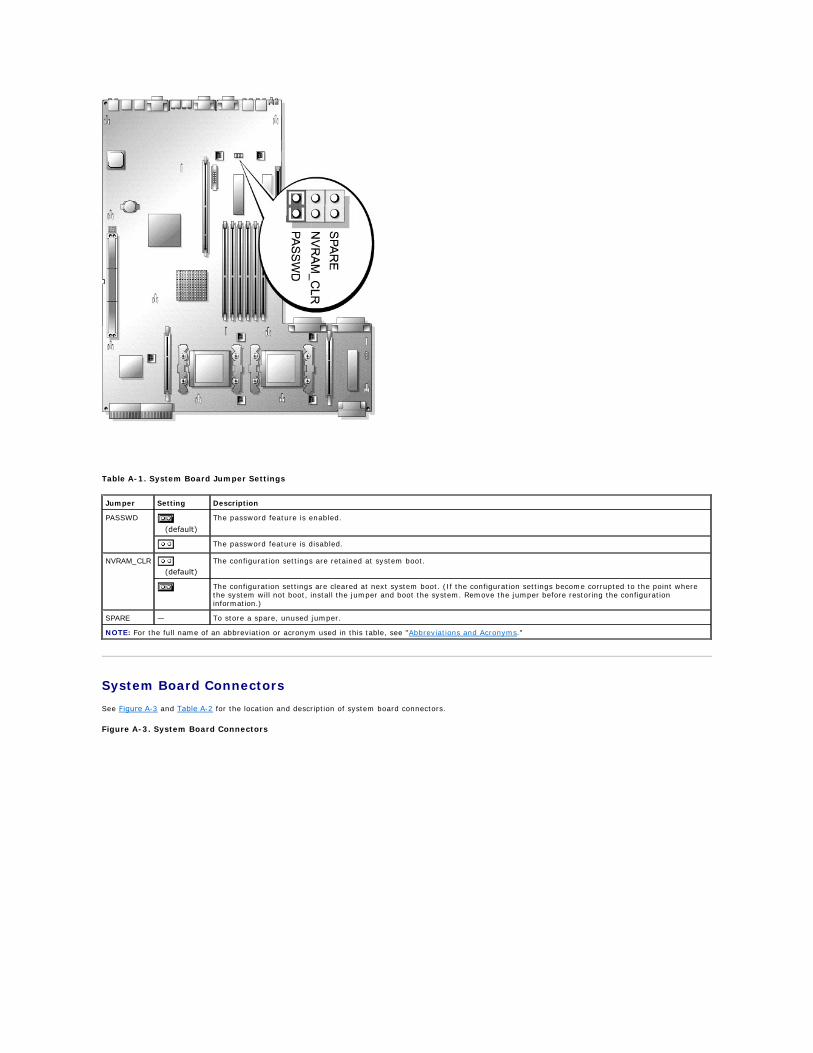
Figure A-2 shows the location and default settings of the system jumper blocks. See Table A-1 for the designations, default settings, and functions of the system's jumpers.
System Board Jumpers
Figure A-2 shows the location of the configuration jumpers on the system board. Table A-1 lists the jumpers settings.
Figure A-2. System Board Jumpers
CAUTION: Ensure that the system is turned off before you change a jumper setting. Otherwise, damage to the system or unpredictable results may occur.
System Board Connectors
See Figure A-3 and Table A-2 for the location and description of system board connectors.
Figure A-3. System Board Connectors
Table A-1. System Board Jumper Settings
Jumper Setting Description
PASSWD (default)
The password feature is enabled.
The password feature is disabled.
NVRAM_CLR (default)
The configuration settings are retained at system boot.
The configuration settings are cleared at next system boot. (If the configuration settings become corrupted to the point where the system will not boot, install the jumper and boot the system. Remove the jumper before restoring the configuration information.)
SPARE — To store a spare, unused jumper.
NOTE: For the full name of an abbreviation or acronym used in this table, see "Abbreviations and Acronyms."

Expansion-Card Riser-Board Components and PCI Buses
Figure A-4 shows the components on the expansion-card riser board, including the expansion-card slots and buses. Table 6-1 lists the PCI bus and operating speed for each expansion-card slot.
Figure A-4. Expansion-Card Riser-Board Components
Table A-2. System Board Connectors
Connector Description
BATTERY System battery
DIMM Xn Memory modules (6), where X is the bank and n is the slot in the bank
FANn Cooling fans:
l 1, 2 — system fans l 3, 4 — microprocessors (2) l 5, 6 — optional l 7 — expansion cards
PROC n Microprocessors (2)
RAID_BAT Battery cable for optional integrated RAID controller
RAID_DIMM Memory module for optional integrated RAID controller
RAID_KEY Hardware key for optional integrated RAID controller
VRM n Microprocessor VRMs (2)
NOTE: For the full name of an abbreviation or acronym used in this table, see "Abbreviations and Acronyms."

SCSI Backplane Board Connectors
Figure A-5 shows the location of the connectors on the SCSI backplane board.
Figure A-5. SCSI Backplane Board Components
Disabling a Forgotten Password
The system's software security features include a system password and a setup password, which are discussed in detail in "Using the System Setup Program" in the User's Guide. The password jumper enables these password features or disables them and clears any password(s) currently in use.
1. Turn off the system, including any attached peripherals, and disconnect the system from the electrical outlet.
2. Remove the cover (see "Removing the Cover" in "Troubleshooting Your System").
3. Remove the jumper plug from the password jumper.
See Figure A-2 to locate of the password jumper (labeled "PASSWD") on the system board.
4. Replace the cover (see "Replacing the Cover" in "Troubleshooting Your System").
5. Reconnect your system and peripherals to their electrical outlets, and turn on the system.
The existing passwords are not disabled (erased) until the system boots with the password jumper plug removed. However, before you assign a new system and/or setup password, you must install the jumper plug.
6. Turn off the system, including any attached peripherals, and disconnect the system from the electrical outlet.
7. Remove the cover (see "Removing the Cover" in "Troubleshooting Your System").
8. Install the jumper plug on the password jumper.
9. Replace the cover (see "Replacing the Cover" in "Troubleshooting Your System").
10. Reconnect your system and peripherals to their electrical outlets, and turn on the system.
11. Assign a new system and/or setup password.
To assign a new passwords using the System Setup program, see "Assigning a System Password" in the User's Guide.
Back to Contents Page
NOTICE: See "Protecting Against Electrostatic Discharge" in the safety instructions in your System Information document.
NOTE: If you assign a new system and/or setup password with the jumper plug still removed, the system disables the new password(s) the next time it boots.


Back to Contents Page
Abbreviations and Acronyms Dell™ PowerEdge™ 2650 Systems Installation and Troubleshooting Guide
A
ampere(s)
AC
alternating current
ADC
analog-to-digital converter
ANSI
American National Standards Institute
APIC
Advanced Peripheral Interrupt Controller
ASIC
application-specific integrated circuit
BIOS
basic input/output system
BMC
baseboard management controller
bpi
bits per inch
bps
bits per second
BTU
British thermal unit
C
Celsius
CD
compact disc
CGA
color graphics adapter
cm
centimeter(s)
CMOS
complementary metal oxide semiconductor
COM
communications
cpi
characters per inch
cpl

characters per line
CPU
central processing unit
DAC
digital-to-analog converter
DAT
digital audio tape
dB
decibel(s)
dBA
adjusted decibel(s)
DC
direct current
DDR
double-data rate
DIMM
dual in-line memory module
DIN
Deutsche Industrie Norm
DIP
dual in-line package
DMA
direct memory access
DOC
Department of Communications (in Canada)
dpi
dots per inch
DRAC III
remote access card
DRAM
dynamic random-access memory
DS/DD
double-sided double-density
DS/HD
double-sided high-density
ECC
error checking and correction
EDO
extended-data out
EGA

enhanced graphics adapter
EIDE
enhanced integrated drive electronics
EMI
electromagnetic interference
EMM
expanded memory manager
EMS
Expanded Memory Specification
EPP
Enhanced Parallel Port
EPROM
erasable programmable read-only memory
ERA
embedded remote access
ESD
electrostatic discharge
ESDI
enhanced small-device interface
ESM
embedded server management
F
Fahrenheit
FAT
file allocation table
FCC
Federal Communications Commission
ft
feet
g
gram(s)
G
gravities
GB
gigabyte(s)
GUI
graphical user interface
Hz
hertz
I/O
input/output

ID
identification
IDE
integrated drive electronics
IRQ
interrupt request
K
kilo- (1024)
KB
kilobyte(s)
KB/sec
kilobyte(s) per second
Kb
kilobit(s)
Kbps
kilobit(s) per second
kg
kilogram(s)
kHz
kilohertz
LAN
local area network
lb
pound(s)
LCD
liquid crystal display
LED
light-emitting diode
LIF
low insertion force
LN
load number
lpi
lines per inch
LVD
low voltage differential
m
meter(s)
mA
milliampere(s)

mAh
milliampere-hour(s)
MB
megabyte(s)
Mb
megabit(s)
Mbps
megabit(s) per second
MBR
master boot record
MDA
monochrome display adapter
MGA
monochrome graphics adapter
MHz
megahertz
mm
millimeter(s)
ms
millisecond(s)
MTBF
mean time between failures
mV
millivolt(s)
NIC
network interface controller
NiCad
nickel cadmium
NiMH
nickel-metal hydride
NMI
nonmaskable interrupt
ns
nanosecond(s)
NTFS
NT File System
NVRAM
nonvolatile random-access memory
OTP
one-time programmable
PAL

programmable array logic
PCI
Peripheral Component Interconnect
PCMCIA
Personal Computer Memory Card International Association
PDB
power distribution board
PDU
power distribution unit
PGA
pin grid array
PIC
personal identification code
POST
power-on self-test
ppm
pages per minute
PQFP
plastic quad flat pack
PSDB
power-supply distribution board
PS/2
Personal System/2
PXE
preboot execution environment
RAID
redundant arrays of independent disks
RAC
Remote access controller
RAM
random-access memory
RCU
Resource Configuration Utility
REN
ringer equivalence number
RFI
radio frequency interference
RGB
red/green/blue
ROM

read-only memory
rpm
revolutions per minute
RTC
real-time clock
SBE
single bit ECC
SCSI
small computer system interface
sec
second(s)
SEC
single-edge contact
SEL
system event log
SDRAM
synchronous dynamic random-access memory
SIMM
single in-line memory module
SMB
server management bus
SMI
system management interrupt
SNMP
Simple Network Management Protocol
SRAM
static random-access memory
SVGA
super video graphics array
TFT
thin film transistor
tpi
tracks per inch
UMB
upper memory block
UPS
uninterruptible power supply
USB
universal serial bus
V
volt(s)

VAC
volt(s) alternating current
VDC
volt(s) direct current
VGA
video graphics array
VLSI
very-large-scale integration
VRAM
video random-access memory
VRM
voltage regulator module
W
watt(s)
WH
watt-hour(s)
XMM
extended memory manager
XMS
eXtended Memory Specification
ZIF
zero insertion force
Back to Contents Page

Back to Contents Page
Introduction Dell™ PowerEdge™ 2650 Systems Installation and Troubleshooting Guide
Other Documents You May Need
Obtaining Technical Assistance
Your system is a high-speed server that offers significant service and upgrade features. The system includes the following service features to make troubleshooting and repair easy and effective:
l Embedded remote access hardware, which monitors temperatures and voltages throughout the system and notifies you if the system overheats, if a system cooling fan malfunctions, or if a power supply fails
l Hot-pluggable cooling fans
l Redundant, hot-pluggable power supplies
l System diagnostics, which checks for hardware problems (if the system can boot)
System upgrade options are offered, including:
l An additional microprocessor
l Additional system memory
l A variety of PCI and PCI-X expansion-card options (including RAID controller cards)
l An integrated RAID controller that can be activated with an additional memory module, key, and battery
Other Documents You May Need
Besides this Installation and Troubleshooting Guide, the following documentation is included with your system:
l The Setting Up Your System sheet provides general instructions for setting up your system.
l The System Information document provides important safety and regulatory information. Warranty information might be included within this document or as a separate document.
l The Rack Installation Guide describes how to unpack, set up, and install your system in a rack.
l The User's Guide describes system features and technical specifications, video and SCSI device drivers, the system setup program, and software support utilities.
l The system management software documentation describes the features, requirements, installation, and basic operation of the systems management software. See the software's online help for information about the alert messages issued by the software.
l Documentation included with any options you purchased separately from the system, which includes information that you need to configure and install these options in your system.
You may also have the following documents.
l Operating system documentation if you ordered an operating system with your system. This documentation describes how to install (if necessary), configure, and use the operating system software.
l Documentation updates are sometimes included with the system to describe changes to the system or software.
l Optional solutions software documentation for web hosting, caching, or load balancing information.
l Technical information files—sometimes called "readme" files—may be installed on the hard drive to provide last-minute updates about technical changes to the system or advanced technical reference material intended for experienced users or technicians.
Obtaining Technical Assistance
If at any time you do not understand a procedure described in this guide or if your system does not perform as expected, a number of tools are provided to help you. For more information on these help tools, see "Getting Help."
Back to Contents Page
NOTE: Always read these updates before consulting any other documentation because the updates often contain information that supersedes the information in the other documents.

Back to Contents Page
Indicators, Messages, and Codes Dell™ PowerEdge™ 2650 Systems Installation and Troubleshooting Guide
System-Status Indicators
System Identification Indicators
Front-Panel Indicators and Features
Back-Panel Indicators and Features
Power Indicator Codes
SCSI Hard-Drive Indicator Codes
NIC Indicator Codes
Cooling Fan Indicator Codes
LCD Status Messages
System Messages
System Beep Codes
Warning Messages
Diagnostics Messages
Alert Messages
Applications, operating systems, and the system itself are capable of identifying problems and alerting you to them. When a problem occurs, a message may appear on the monitor or front-panel status LCD, or a beep code may sound.
A variety of messages and codes can indicate when the system is not functioning properly:
l System-status indicators
l System identification identifiers
l Front-panel indicators and features
l Back-panel indicators and features
l Power indicator codes
l SCSI hard-drive indicator codes
l NIC indicator codes
l Cooling fan indicator codes
l LCD status messages
l System messages
l System beep codes
l Warning messages
l Diagnostics messages
l Alert messages
The system indicators and features are illustrated in Figure 2-1 through Figure 2-6. This section also describes each type of message, and lists the possible causes and actions you can take to resolve any problems indicated by a message. To determine what type of message you have received, read the following subsections.
System-Status Indicators
The system's bezel has an indictor that can represent system status when the bezel is installed (see Figure 2-1). The indicator signifies when the system is operating properly or when the system needs attention. The back-panel indicator functions the same as the bezel indicator. The back-panel indicator connector allows an indicator to be attached that will also function the same as the bezel indicator (see Figure 2-3).
A caution code signifies a problem with microprocessors, power supply, system or power-supply fans, system temperature, hard drives, system memory, expansion cards, or integrated SCSI controller.
Table 2-1 lists the system's status indicator codes.
Figure 2-1. System-Status Indicators

System Identification Indicators
The identification buttons on the front and back panels can be used to identify a particular system within a rack. See Figure 2-2 to locate the front-panel system identification button. See Figure 2-3 to locate the back-panel system identification button and indicator.
When either of the identification buttons is pushed, the identification indicator on the back blinks until one of the buttons is pushed again. If the bezel is installed, the system status indicator will also blink. If an indicator is connected to the back-panel system status indicator connector, that indicator will also blink.
Systems management software can also be used to cause the status and identification indicators to blink to identify a particular system. For more information, see the systems management software documentation.
Front-Panel Indicators and Features
Additional indicators are located behind the bezel. The front-panel status LCD provides information using an alphanumeric character display (see "LCD Status Messages"). See Figure 2-2 for the front-panel indicators and features.
Figure 2-2 shows the front-panel features of the system. Table 2-2 describes the front-panel features.
Figure 2-2. Front-Panel Features
Table 2-1. System-Status Indicator Codes
Bezel Indicators Back-Panel Indicators Indicator Code
Status Caution
Off Off Off No power is available to the system, or the system is not powered on.
On Off Blue The system is operating normally.
Off Blinking Amber blinking The system has detected an error and requires attention.
Blinking Off Blue blinking The system is identifying itself (see "System Identification Indicators").
Table 2-2. Front-Panel Features
Component Description
Power button Turns system power off and on.

Back-Panel Indicators and Features
Figure 2-3 shows the back-panel features of the system. Table 2-3 describes the back-panel features.
Figure 2-3. Back-Panel Features
Power Indicator Codes
The system has indicators on the front panel and the power supplies that signify system power status.
Power-Button Indicator Codes
l If you turn off the system using the power button and the system is running an ACPI-compliant operating system (such as Microsoft® Windows® 2000), the system can perform an orderly shutdown before power is turned off.
l If the system is not running an ACPI-compliant operating system, power is turned off immediately after the power button is pressed.
The button is enabled in the System Setup program. When disabled, the button can only turn system power on. For more information, see the User's Guide and the operating system's documentation.
Power indicator Provides information on power status (see "Power Indicator Codes").
CD and diskette drive indicators
Indicates read or write access to the respective drive.
hard-drive indicators
Provide information on the status of the respective hard drive (see "SCSI Hard-Drive Indicator Codes").
NIC indicators Indicate whether the NIC has a valid link to the network (see "NIC Indicator Codes").
Status LCD Can signify when the system is operating correctly or when the system needs attention (see "LCD Status Messages").
System identification button
Can be used to identify a particular system (see "System Identification Indicators").
NMI button Can be used to troubleshoot software and device driver errors when using certain operating systems. This button is often referred to as a "force dump switch" and can be pressed using the end of a paper clip. When the option is enabled in the System Setup program and the button is pressed, an NMI alerts the system.
Use this button only if directed to do so by qualified support personnel or by the operating system's documentation. For more information, see the User's Guide and the operating system's documentation.
Table 2-3. Back-Panel Features
Component Description
Power supply indicators Provides information on power status (see "Power Indicator Codes").
NIC indicators Provides information on NIC status (see "NIC Indicator Codes").
System status indicator connector
Connects to an indicator that can signify when the system is operating correctly or when the system needs attention (see "System-Status Indicators").
System identification indicator
Signifies when the system is operating correctly or when the system needs attention, and can identify a particular system (see "System Identification Indicators").
System identification button Can be used to identify a particular system (see "System Identification Indicators").

The power button controls the power input to the system's power supplies. The power button indicator can provide information on power status (see Figure 2-2).
Table 2-4 lists the power button indicator codes.
Power-Supply Indicator Codes
Each hot-pluggable power supply has indicators that can provide information on power status, fault, and the presence of power (see Figure 2-4). Table 2-5 lists the power-supply indicator codes.
Figure 2-4. Power-Supply Indicators
SCSI Hard-Drive Indicator Codes
Each SCSI hard-drive carrier has two indicators: a busy indicator and a status indicator (see Figure 2-5). The indicators provide information on the status of the respective hard drive. Table 2-6 lists the drive indicator codes.
Figure 2-5. SCSI Hard-Drive Indicators
Table 2-4. Power-Button Indicator Codes
Indicator Indicator Code
On Indicates that power is supplied to the system, and the system is operational.
Off Indicates that no power is supplied to the system.
Blinking Indicates that power is supplied to the system, but the system is in a standby state. For more information on standby states, see your operating system documentation.
Table 2-5. Power-Supply Indicator Codes
Indicator Indicator Code
Power-on Green indicates that the power supply is operational.
Fault Red indicates a problem with the power supply (fan failure, voltage error, etc.).
Power present Green indicates that power is present at the power supply and that the system is connected to a power source.

Table 2-6 lists the drive indicator codes. Different codes display as drive events occur in the system. For example, in the event of a hard-drive failure, the "drive fail" code appears. After the drive is selected for removal, the "preparing for removal" code appears. After the replacement drive is installed, the "preparing for operation, drive online" code appears.
NIC Indicator Codes
Each NIC on the back panel has an indicator that provides information on network activity and link status (see Figure 2-6). Table 2-7 lists the NIC indicator codes on the back panel.
The front panel has a link indicator for each NIC (see Figure 2-2). Each indicator signifies whether the corresponding NIC is connected to a valid link partner on the network.
Figure 2-6. NIC Indicators
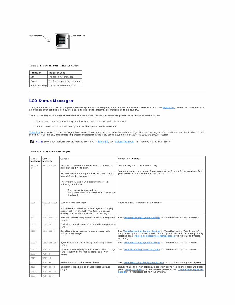
Cooling Fan Indicator Codes
Each individual fan has a status indicator on the system board adjacent to the respective fan's connector (see Figure 2-7). To locate the fan connectors on the system board, see Figure A-3. Table 2-8 lists the fan indicator codes.
Figure 2-7. Cooling Fan Indicators
Table 2-6. SCSI Hard-Drive Indicator Codes
Drive Status Indicator Indicator Code
Drive bay empty, ready for insertion or removal Off
Drive being prepared for operation, drive online Steady green
Drive being identified Blinks green four times per second
Drive being prepared for removal Blinks green twice per second at equal intervals
Drive rebuilding Blinks green twice per second at unequal intervals
Drive failed Blinks amber four times per second
Predicted failure for the drive Blinks green, then amber, and then off, repeating this sequence every two seconds
NOTE: The drive busy indicator signifies whether the hard drive is active on the SCSI bus. This indicator is controlled by the hard drive.
Table 2-7. NIC Indicator Codes
Indicator Indicator Code
Link and activity indicators are off The NIC is not connected to the network.
Link indicator is green The NIC is connected to a valid link partner on the network.
Activity indicator is amber blinking Network data is being sent or received.
LCD Status Messages
The system's bezel indictor can signify when the system is operating correctly or when the system needs attention (see Figure 2-1). When the bezel indicator signifies an error condition, remove the bezel to see further information provided by the status LCD.
The LCD can display two lines of alphanumeric characters. The display codes are presented in two color combinations:
l White characters on a blue background — Information only; no action is required.
l Amber characters on a black background — The system needs attention.
Table 2-9 lists the LCD status messages that can occur and the probable cause for each message. The LCD messages refer to events recorded in the SEL. For information on the SEL and configuring system management settings, see the systems management software documentation.
Table 2-8. Cooling Fan Indicator Codes
Indicator Indicator Code
Off The fan is not installed.
Green The fan is operating normally.
Amber blinking The fan is malfunctioning.
NOTE: Before you perform any procedures described in Table 2-9, see "Before You Begin" in "Troubleshooting Your System."
Table 2-9. LCD Status Messages
Line 1 Message
Line 2 Message
Causes Corrective Actions
SYSTEM
ID
SYSTEM NAME SYSTEM ID is a unique name, five characters or less, defined by the user.
SYSTEM NAME is a unique name, 16 characters or less, defined by the user.
The system ID and name display under the following conditions:
l The system is powered on. l The power is off and active POST errors are
displayed.
This message is for information only.
You can change the system ID and name in the System Setup program. See your system's User's Guide for instructions.
E0000 OVRFLW CHECK
LOG
LCD overflow message.
A maximum of three error messages can display sequentially on the LCD. The fourth message displays as the standard overflow message.
Check the SEL for details on the events.
E0119 TEMP AMBIENT Ambient system temperature is out of acceptable range.
See "Troubleshooting System Cooling" in "Troubleshooting Your System."
E0119 TEMP BP Backplane board is out of acceptable temperature range.
E0119 TEMP CPU n Specified microprocessor is out of acceptable temperature range.
See "Troubleshooting System Cooling" in "Troubleshooting Your System." If the problem persists, ensure that the microprocessor heat sinks are properly installed (see "Adding or Replacing a Microprocessor" in "Installing System Options").
E0119 TEMP SYSTEM System board is out of acceptable temperature range.
See "Troubleshooting System Cooling" in "Troubleshooting Your System."
E0212 VOLT 3.3 System power supply is out of acceptable voltage range; faulty or improperly installed power supply.
See "Troubleshooting Power Supplies" in "Troubleshooting Your System."
E0212 VOLT 5
E0212 VOLT 12
E0212 VOLT BATT Faulty battery; faulty system board. See "Troubleshooting the System Battery" in "Troubleshooting Your System."
E0212 VOLT BP 12 Backplane board is out of acceptable voltage range.
Ensure that the power cables are securely connected to the backplane board (see "Installing Drives"). If the problem persists, see "Troubleshooting Power Supplies" in "Troubleshooting Your System." E0212 VOLT BP 3.3
E0212 VOLT BP 5

E0212 VOLT CPU VRM Microprocessor VRM voltage is out of acceptable range; faulty or improperly installed microprocessor VRM; faulty system board.
Ensure that supported VRMs of the same type are properly installed. If the problem persists, replace the VRMs (see Figure 6-9). If the problem persists, see "Getting Help."
E0212 VOLT NIC 1.8V Integrated NIC voltage is out of acceptable range; faulty or improperly installed power supply; faulty system board.
See "Troubleshooting Power Supplies" in "Troubleshooting Your System."
E0212 VOLT NIC 2.5V
E0212 VOLT PLANAR
REG
System board is out of acceptable voltage range; faulty or improperly installed system board.
E0276 CPU VRM n Specified microprocessor VRM is faulty, unsupported, improperly installed, or missing.
Ensure that supported VRMs of the same type are properly installed. If the problem persists, replace the VRM (see Figure 6-9 in "Installing System Options"). E0276 MISMATCH VRM
n
E0280 MISSING VRM n
E0319 PCI OVER
CURRENT
Faulty or improperly installed expansion card. See "Troubleshooting Expansion Cards" in "Troubleshooting Your System."
E0412 RPM FAN n Specified cooling fan is faulty, improperly installed, or missing.
See "Troubleshooting a Cooling Fan" in "Troubleshooting Your System."
E0780 MISSING CPU 1 Microprocessor is not installed in socket 1. Install a microprocessor in socket 1 (see "Adding or Replacing a Microprocessor" in "Installing System Options"). To identify microprocessor socket 1, see Figure A-3.
E07F0 CPU IERR Faulty or improperly installed microprocessor. See "Troubleshooting a Microprocessor" in "Troubleshooting Your System."
E07F1 TEMP CPU n
HOT
Specified microprocessor is out of acceptable temperature range and has halted operation.
See "Troubleshooting System Cooling" in "Troubleshooting Your System." If the problem persists, ensure that the microprocessor heat sinks are properly installed (see "Adding or Replacing a Microprocessor" in "Installing System Options").
E07F4 POST CACHE Faulty or improperly installed microprocessor. See "Troubleshooting a Microprocessor" in "Troubleshooting Your System."
E07F4 POST CPU REG
E07F4 POST CPU SMI SMI handler failed to initialize; faulty system board.
See "Getting Help."
E07FA TEMP CPU n
THERM
Specified microprocessor is out of acceptable temperature range and is operating at a reduced speed, or frequency.
See "Troubleshooting System Cooling" in "Troubleshooting Your System." If the problem persists, ensure that the microprocessor heat sinks are properly installed (see "Adding or Replacing a Microprocessor" in "Installing System Options").
E0876 POWER PS n No power available from the specified power supply; specified power supply is improperly installed or faulty.
See "Troubleshooting Power Supplies" in "Troubleshooting Your System."
E0880 INSUFFICIENT
PS
Insufficient power is being supplied to the system; power supplies are improperly installed, faulty, or missing.
See "Troubleshooting Power Supplies" in "Troubleshooting Your System."
E0CB2 MEM SPARE ROW Correctable errors threshold was met in a memory bank: errors were remapped to the spare row.
See "Troubleshooting System Memory" in "Troubleshooting Your System."
E0CF1 MBE DIMM Bank
n
Memory modules installed in the specified bank are not the same type and size; faulty memory module(s).
Ensure that all banks contain memory modules of the same type and size and that they are properly installed. If the problem persists, see "Troubleshooting System Memory" in "Troubleshooting Your System."
E0CF1 POST MEM 64K Parity failure in the first 64 KB of main memory. See "Troubleshooting System Memory" in "Troubleshooting Your System."
E0CF1 POST NO
MEMORY
Main-memory refresh verification failure. Ensure that all banks contain memory modules of the same type and size and that they are properly installed. If the problem persists, see "Troubleshooting System Memory" in "Troubleshooting Your System."
E0CF5 LOG DISABLE
SBE
Multiple single-bit errors on a single memory module.
See "Troubleshooting System Memory" in "Troubleshooting Your System."
E0D76 DRIVE FAIL Faulty or improperly installed hard drive or RAID controller.
See "Troubleshooting Hard Drives" and "Troubleshooting a RAID Controller Card" in "Troubleshooting Your System."
E0F04 POST CMOS CMOS write/read failure; faulty system board. See "Getting Help."
E0F04 POST CPU
SPEED
Microprocessor speed control sequence failure. See "Getting Help."
E0F04 POST DMA INIT DMA initialization failure; DMA page register write/read failure.
See "Troubleshooting System Memory" in "Troubleshooting Your System."
E0F04 POST DMA REG Faulty system board. See "Getting Help."
E0F04 POST KYB
CNTRL
Faulty keyboard controller; faulty system board. See "Getting Help."
E0F04 POST MEM RFSH Main-memory refresh verification failure. See "Troubleshooting System Memory" in "Troubleshooting Your System."
E0F04 POST PIC REG Master or slave PIC register test failure. See "Getting Help."
E0F04 POST SHADOW BIOS-shadowing failure. See "Troubleshooting System Memory" in "Troubleshooting Your System."
E0F04 POST SHD TEST Shutdown test failure.
E0F04 POST SIO Super I/O chip failure; faulty system board. See "Getting Help."
E0F04 POST TIMER Programmable interval timer test failure; faulty system board.
See "Getting Help."
E0F0B POST ROM
CHKSUM
Faulty or improperly installed expansion card. See "Troubleshooting Expansion Cards" in "Troubleshooting Your System."
E0F0C VID MATCH CPU
n
Specified microprocessor is faulty, unsupported, improperly installed, or missing.
See "Troubleshooting a Microprocessor" in "Troubleshooting Your System."
E10F3 LOG DISABLE BIOS disabled logging errors. Check the SEL for details on the errors.

Solving Problems Described by LCD Status Messages
When a single message appears on the status LCD, locate the code in Table 2-9 and perform the suggested corrective action. The code on the LCD can often specify a very precise fault condition that is easily corrected. For example, if the code E0280 MISSING VRM 2 appears, you know that a microprocessor is
installed in socket 2, but the VRM for that microprocessor is either improperly installed or missing.
In contrast, you might be able to determine the problem if multiple related errors occur. For example, if you receive a series of messages indicating multiple voltage faults, you might determine that the problem is a failing power supply.
Removing LCD Status Messages
For faults associated with sensors, such as temperature, voltage, fans, and so on, the LCD message is automatically removed when that sensor returns to a normal state. For example, if temperature for a component goes out of range, the LCD displays the fault; when the temperature returns to the acceptable range, the message is removed from the LCD. For other faults, you must take action to remove the message from the display:
l Clear the SEL — You can perform this task remotely, but you will lose the event history for the system.
l Chassis intrusion — When you remove the cover, the system assumes that you are servicing the bad component; the LCD clears when you replace the cover.
l Power cycle — Turn off the system and disconnect it from the electrical outlet; wait approximately ten seconds, reconnect the power cable, and restart the system.
Any of these actions will remove fault messages, and return the status indicators and LCD colors to the normal state. Messages will reappear under the following conditions:
l The sensor returns to a normal state but fails again, resulting in a new SEL entry.
l The system is reset and new error events are detected.
l A failure is recorded from another source that maps to the same display entry.
System Messages
System messages appear on the console during POST to notify you of a possible problem with the system. If you are performing console redirection, system messages will appear on the remote console. Table 2-10 lists the system messages that can occur and the probable cause for each message.
BIOS
E13F2 IO CHANNEL
CHECK
Faulty or improperly installed expansion card; faulty system board.
See "Troubleshooting Expansion Cards" in "Troubleshooting Your System."
E13F4 PCI PARITY
E13F5 PCI SYSTEM
E13F8 CPU BUS INIT Faulty or improperly installed microprocessor or system board.
See "Troubleshooting a Microprocessor" in "Troubleshooting Your System." If the problem persists, see "Getting Help."
E13F8 CPU BUS
PARITY
Faulty system board. See "Getting Help."
E13F8 CPU MCKERR Machine check error; faulty or improperly installed microprocessor; faulty system board.
See "Troubleshooting a Microprocessor" in "Troubleshooting Your System."
E13F8 HOST BUS Faulty system board. See "Getting Help."
E13F8 HOST TO PCI
BUS
E13F8 MEM
CONTROLLER
Faulty or improperly installed memory module; faulty system board.
See "Troubleshooting System Memory" in "Troubleshooting Your System."
E1580 POWER CONTROL Faulty system board. See "Getting Help."
E20F1 OS HANG Operating system watchdog timer timed out. Restart your system. If the problem persists, see your operating system documentation.
EFFF0 RAC ERROR Remote access controller firmware failure; faulty system board.
See "Getting Help."
EFFF1 POST ERROR BIOS error. Update the BIOS firmware (see "Getting Help").
EFFF2 BP ERROR Faulty or improperly installed backplane board. Ensure that the interface cables are securely connected to the backplane board (see "Installing Drives"). If the problem persists, see "Getting Help."
NOTE: For the full name of an abbreviation or acronym used in this table, see "Abbreviations and Acronyms."
NOTE: If you receive a system message that is not listed in Table 2-10, check the documentation for the application program that is running when the message appears or the operating system's documentation for an explanation of the message and recommended action.
NOTE: Before you perform any procedures described in Table 2-10, see "Before You Begin" in "Troubleshooting Your System."
Table 2-10. System Messages
Message Causes Corrective Actions
Address mark not found Faulty CD/diskette drive subsystem or hard-drive subsystem; faulty system board.
See "Troubleshooting the Diskette Drive," "Troubleshooting a CD Drive," and "Troubleshooting Hard Drives" in "Troubleshooting Your System."
Alert! Current configuration does not support Memory modules installed are not the Ensure that all banks contain memory modules of the same

redundant memory. Redundant memory is disabled. same type and size in all banks; faulty memory module(s).
type and size and that they are properly installed. If the problem persists, see "Troubleshooting System Memory" in "Troubleshooting Your System."
Alert! Unsupported memory or incomplete sets in
the following bank(s): Bank x
Memory modules installed in the specified bank are not the same type and size; faulty memory module(s).
Ensure that all banks contain memory modules of the same type and size and that they are properly installed. If the problem persists, see "Troubleshooting System Memory" in "Troubleshooting Your System."
Amount of available memory limited to 256 MB! OS Install Mode is enabled in the System Setup program.
Disable OS Install Mode in the System Setup program (see "Using the System Setup program" in the User's Guide).
Auxiliary device failure Loose or improperly connected mouse or keyboard cable; faulty mouse or keyboard.
See "Troubleshooting the Mouse" and "Troubleshooting the Keyboard" in "Troubleshooting Your System."
BIOS Update Attempt Failed! Remote BIOS update attempt failed. Retry the BIOS update. If problem persists, see "Getting Help."
CD-ROM drive not found Improperly connected or missing CD drive.
See "Troubleshooting a CD Drive" in "Troubleshooting Your System."
CPUs with different cache sizes detected Microprocessors with different cache sizes are installed.
Ensure that all microprocessors have the same cache size and that they are properly installed (see "Adding or Replacing a Microprocessor" in "Installing System Options").
Decreasing available memory Faulty or improperly installed memory modules.
See "Troubleshooting System Memory" in "Troubleshooting Your System."
Diskette drive n seek failure Incorrect configuration settings in the System Setup program.
Run the System Setup program to correct the settings (see "Using the System Setup Program" in the User's Guide).
Faulty or improperly installed diskette drive.
See "Troubleshooting the Diskette Drive" in "Troubleshooting Your System."
Diskette read failure Faulty or improperly inserted diskette. Replace the diskette.
Diskette subsystem reset failed Faulty or improperly installed diskette drive.
See "Troubleshooting the Diskette Drive" in "Troubleshooting Your System."
ECC memory error Faulty or improperly installed memory modules.
See "Troubleshooting System Memory" in "Troubleshooting Your System."
Remote access controller error Embedded remote access memory may be temporarily corrupted.
To clear the embedded remote access memory, shut down the system, disconnect the power cords, wait approximately 30 seconds, reconnect the power cords, and restart the system. If the problem persists, see "Getting Help."
Remote access controller is not present
Error: Maximum PCI option ROM count exceeded! Too many expansion cards have ROM enabled in the System Setup program.
Disable ROM for some of the expansion cards. See "Using the System Setup Program" in the User's Guide.
Gate A20 failure Faulty keyboard controller; faulty system board.
See "Getting Help."
Hard disk controller failure Incorrect configuration settings in System Setup program; improperly installed hard drive, or loose interface or power cable; faulty hard-drive controller subsystem.
Run the System Setup program to correct the drive type (see "Using the System Setup Program" in the User's Guide). If the problem persists, see "Troubleshooting Hard Drives" in "Troubleshooting Your System." Hard disk read failure
I/O parity interrupt at address Faulty or improperly installed expansion card.
See "Troubleshooting Expansion Cards" in "Troubleshooting Your System."
Invalid configuration information - please run
SETUP program
Incorrect configuration settings in System Setup program; NVRAM_CLR jumper is installed; faulty system battery.
Check the System Setup configuration settings (see "Using the System Setup Program" in the User's Guide). Remove the NVRAM_CLR jumper (see Figure A-2 for jumper location). If the problem persists, see "Troubleshooting the System Battery" in "Troubleshooting Your System."
Invalid NVRAM configuration, resource re-
allocated
System configuration data has been ignored.
Check the System Setup configuration settings. See "Using the System Setup Program" in the User's Guide.
Invalid SCSI configuration
SCSI cable detected on connector SCSIB of the
SCSI backplane, daughter card not present
A SCSI cable is connected to the channel B connector on the SCSI backplane board; SCSI backplane daughter card is not installed.
If a cable is connected to the SCSIB backplane board connector, the SCSI backplane daughter card must be installed. Install the backplane daughter card (see "Installing a SCSI Backplane Daughter Card" in "Installing Drives").
Keyboard controller failure Faulty keyboard controller; faulty system board.
See "Getting Help."
Keyboard clock line failure Loose or improperly connected keyboard cable; faulty keyboard; faulty keyboard controller.
See "Troubleshooting the Keyboard" in "Troubleshooting Your System."
Keyboard data line failure
Keyboard failure
Keyboard stuck key failure
Memory address line failure at address, read
value expecting value
Faulty or improperly installed memory modules.
See "Troubleshooting System Memory" in "Troubleshooting Your System."
Memory double word logic failure at address, read
value expecting value
Memory high address line failure at start address
to end address
Memory high data line failure at start address to
end address
Memory odd/even logic failure at start address to
end address
Memory write/read failure at address, read value

expecting value
Memory parity failure at start address to end
address
Faulty or improperly installed memory modules.
See "Troubleshooting System Memory" in "Troubleshooting Your System."
Memory parity error at address
No boot device available Faulty or missing CD/diskette drive subsystem, hard drive, or hard-drive subsystem.
Use a bootable diskette, CD, or hard drive. If the problem persists, see "Troubleshooting the Diskette Drive," "Troubleshooting a CD Drive," and "Troubleshooting Hard Drives" in "Troubleshooting Your System."
No boot sector on hard- disk No operating system on hard drive. Check the hard-drive configuration settings in the System Setup program (see "Using the System Setup Program" in the User's Guide).
No PXE-capable device available <F12> pressed during POST and no PXE devices are detected.
Check the configuration settings in the System Setup program for the NICs (see "Using the System Setup Program" in the User's Guide). If the problem persists, see "Troubleshooting the NICs" in "Troubleshooting Your System."
No timer tick interrupt Faulty system board. See "Getting Help."
Not a boot diskette No operating system on diskette. Use a bootable diskette.
PCI BIOS failed to install Loose cables to expansion card(s); faulty or improperly installed expansion card.
Ensure that all appropriate cables are securely connected to the expansion cards. If the problem persists, see "Troubleshooting Expansion Cards" in "Troubleshooting Your System."
Plug & Play Configuration Error Embedded xxx Error encountered in initializing PCI device; faulty system board.
Install the NVRAM_CLR jumper and reboot the system (see Figure A-2 for jumper location). If the problem persists, see "Troubleshooting Expansion Cards" in "Troubleshooting Your System." Plug & Play Configuration Error PCI_n Error encountered in initializing PCI
adapter.
Primary backplane is not present Faulty or improperly installed SCSI backplane board.
See "Getting Help."
Processor n internal error Faulty microprocessor; faulty system board.
See "Troubleshooting a Microprocessor" in "Troubleshooting Your System."
Processor bus parity error
Processor in socket 1 not installed! No microprocessor installed in primary microprocessor socket.
Install a microprocessor in the primary microprocessor socket. Also, ensure that a VRM for processor 1 is installed (see "Adding or Replacing a Microprocessor" in "Installing System Options").
SCSI cable not present on connector A or B of the
primary backplane
SCSI cable is loose, improperly connected, or faulty.
Check the SCSI cable connection. If problem persists, add or replace SCSI cable (see "Getting Help").
Shutdown failure Shutdown test failure. See "Troubleshooting System Memory" in "Troubleshooting Your System."
System backplane error Faulty or improperly installed SCSI backplane board.
See "Getting Help."
System halted! Must power down Wrong password entered too many times.
Information only.
Time-of-day clock stopped Faulty battery. See "Troubleshooting the System Battery" in "Troubleshooting Your System."
Time-of-day not set - please run SETUP program Incorrect Time or Date settings; faulty system battery.
Check the Time and Date settings (see "Using the System Setup Program" in the User's Guide). If the problem persists, replace the system battery (see "Replacing the System Battery" in "Installing System Options").
Timer chip counter 2 failed Faulty system board. See "Getting Help."
Unsupported CPU combination Microprocessor(s) is not supported by the system.
Install a supported microprocessor combination (see "Adding or Replacing a Microprocessor" in "Installing System Options"). Unsupported CPU stepping detected
Unsupported DIMM detected in the RAID DIMM slot! RAID memory module is not supported by the system.
Install a correct version of the RAID memory module (see "Activating the Integrated RAID Controller" in "Installing Drives").
Unsupported RAID key detected! RAID hardware key is not supported by the system.
Install the RAID hardware key for your specific system (see "Activating the Integrated RAID Controller" in "Installing Drives").
Utility partition not available The <F10> key was pressed during POST, but no utility partition exists on the boot hard drive.
Create a utility partition on the boot hard drive (see "Using the Dell OpenManage Server Assistant CD" in your User's Guide).
The VRM for the processor in socket n is not
installed.
Specified microprocessor VRM is faulty, unsupported, improperly installed, or missing.
Ensure that supported VRMs of the same type are properly installed. If the problem persists, replace the VRM (see Figure 6-9).
Warning: Detected mode change from RAID to SCSI B
of the embedded RAID subsystem.
Type of controller has changed since previous system boot.
Back up information on the hard drives before changing the type of controller used with the drives.
Warning: Detected missing RAID hardware for the
embedded RAID subsystem. Data loss will occur!
Press Y to switch mode to SCSI, press any other
key to disable both channels. Press Y to confirm
the change; press any other key to cancel.
Warning: Firmware is out- of-date, please update. Firmware error. Update the firmware (see "Getting Help").
Warning! No microcode update loaded for processor
X
BIOS error. Update the BIOS firmware (see "Getting Help").
Write fault Faulty diskette, CD/diskette drive assembly, hard drive, or hard-drive subsystem.
See "Troubleshooting the Diskette Drive," "Troubleshooting a CD Drive," and "Troubleshooting Hard Drives" in "Troubleshooting Your System." Write fault on selected drive

System Beep Codes
When an error that cannot be reported on the monitor occurs during a boot routine, the system may emit a series of beeps that identifies the problem.
When a beep code is emitted, record it on a copy of the Diagnostics Checklist in "Getting Help," and then look it up in Table 2-11. If you are unable to resolve the problem by looking up the meaning of the beep code, use the system diagnostics to identify a more serious cause. If you are still unable to resolve the problem, see "Getting Help."
NOTE: For the full name of an abbreviation or acronym used in this table, see "Abbreviations and Acronyms."
NOTE: If the system boots without a keyboard, mouse, or monitor attached, the system will not issue beep codes related to those peripherals.
NOTE: Before you perform any procedures described in Table 2-11, see "Before You Begin" in "Troubleshooting Your System."
Table 2-11. System Beep Codes
Code Cause Corrective Action
1-1-2 CPU register test failure. Replace microprocessor 1. See "Adding or Replacing a Microprocessor" in "Installing System Board Options." If the problem persists, replace microprocessor 2.
1-1-3 CMOS write/read failure; faulty system board.
See "Getting Help."
1-1-4 BIOS error. Reflash the BIOS firmware (see "Getting Help").
1-2-1 Programmable interval-timer failure; faulty system board.
See "Getting Help."
1-2-2 DMA initialization failure. See "Troubleshooting System Memory" in "Troubleshooting Your System."
1-2-3 DMA page register write/read failure.
1-3-1 Main-memory refresh verification failure.
1-3-2 No memory installed.
1-3-3 Chip or data line failure in the first 64 KB of main memory.
1-3-4 Odd/even logic failure in the first 64 KB of main memory.
1-4-1 Address line failure in the first 64 KB of main memory.
1-4-2 Parity failure in the first 64 KB of main memory.
1-4-3 Fail-safe timer test failure.
1-4-4 Software NMI port test failure.
2-1-1
through 2-4-4
Bit failure in the first 64 KB of main memory.
3-1-1 Slave DMA-register failure. See "Getting Help."
3-1-2 Master DMA-register failure.
3-1-3 Master interrupt-mask register failure.
3-1-4 Slave interrupt-mask register failure.
3-2-2 Interrupt vector loading failure.
3-2-4 Keyboard-controller test failure. See "Troubleshooting the Keyboard" in "Troubleshooting Your System."
3-3-1 CMOS failure. See "Getting Help."
3-3-2 System configuration check failure.
3-3-3 Keyboard controller not detected.
3-3-4 Video memory test failure.
3-4-1 Screen initialization failure.
3-4-2 Screen-retrace test failure.
3-4-3 Video ROM search failure.
4-2-1 No timer tick.
4-2-2 Shutdown test failure.
4-2-3 Gate A20 failure.
4-2-4 Unexpected interrupt in protected mode. See "Troubleshooting Expansion Cards" in "Troubleshooting Your System."
4-3-1 Improperly installed or faulty memory modules.
See "Troubleshooting System Memory" in "Troubleshooting Your System."
4-3-2 No memory modules installed in bank 1. Install memory modules in bank 1 of the same type and size (see "Installing Memory Modules" in "Installing System Options").
4-3-3 Faulty system board. See "Getting Help."
4-3-4 Time-of-day clock stopped. See "Troubleshooting the System Battery" in "Troubleshooting Your System."

Warning Messages
A warning message alerts you to a possible problem and asks you to take corrective action before the system continues a task. For example, before you format a diskette, a message may warn you that you may lose all data on the diskette. Warning messages usually interrupt the procedure and require you to respond by typing y (yes) or n (no).
Diagnostics Messages
When you run a test group or subtest in system diagnostics, an error message may result. Diagnostic error messages are not covered in this section. Record the message on a copy of the Diagnostics Checklist (see "Getting Help"), and then follow the instructions in that section for obtaining technical assistance.
Alert Messages
The optional systems management software generates alert messages for your system. For example, the software generates messages that appear in the SNMP trap log file. Alert messages consist of information, status, warning, and failure messages for drive, temperature, fan, and power conditions. For more information, see the systems management software documentation.
Back to Contents Page
4-4-1 Super I/O chip failure; faulty system board.
See "Getting Help."
4-4-2 BIOS-shadowing failure. See "Troubleshooting System Memory" in "Troubleshooting Your System."
4-4-3 Microprocessor speed control sequence failure.
See "Troubleshooting a Microprocessor" in "Troubleshooting Your System."
4-4-4 Cache test failure; faulty microprocessor.
NOTE: For the full name of an abbreviation or acronym used in this table, see "Abbreviations and Acronyms."
NOTE: Warning messages are generated by either the application program or the operating system. For more information, see "Finding Software Solutions" and the documentation that accompanied the operating system or application program.

Back to Contents Page
Finding Software Solutions Dell™ PowerEdge™ 2650 Systems Installation and Troubleshooting Guide
Installing and Configuring Software
Using Software
Because most systems have several application programs installed in addition to the operating system, isolating a software problem can be confusing. Software errors can also appear to be hardware malfunctions at first.
Software problems can result from the following circumstances:
l Improper installation or configuration of a program
l Input errors
l Device drivers that may conflict with certain application programs
l Interrupt conflicts between devices
You can confirm that a system problem is caused by software by running system diagnostics. If all tests in the test group are completed successfully, the problem is most likely caused by software.
This section provides some general guidelines for analyzing software problems. For detailed troubleshooting information on a particular program, see the documentation that accompanied the software or consult the support service for the software.
Installing and Configuring Software
Use virus-scanning software to check newly acquired programs and files for viruses before installing the programs on the system's hard drive. Viruses can quickly use all available system memory, damage or destroy data stored on the hard drive, and permanently affect the performance of the programs they infect. Several commercial virus-scanning programs are available for purchase.
Before installing a program, read its documentation to learn how the program works, what hardware it requires, and what its defaults are. A program usually includes installation instructions in its accompanying documentation and a software installation routine.
The software installation routine assists users in transferring the appropriate program files to the system's hard drive. Installation instructions may provide details about how to configure the operating system to successfully run the program. Always read the installation instructions before running a program's installation routine.
When you run the installation routine, be prepared to respond to prompts for information about how the system's operating system is configured, what type of system you have, and what peripherals are connected to the system.
Using Software
The following subsections discuss errors that can occur as a result of software operation or configuration.
Error Messages
Error messages can be produced by an application program, the operating system, or the system. "Indicators, Messages, and Codes" discusses the error messages that are generated by the system. If you receive an error message that is not listed in "Indicators, Messages, and Codes," check the operating system or application program documentation.
Input Errors
If a specific key or set of keys is pressed at the wrong time, a program may give you unexpected results. See the documentation that came with the application program to make sure that the values or characters you are entering are valid.
Ensure that the operating environment is set up to accommodate the programs you use. Remember that whenever you change the parameters of the system's operating environment, you may affect the successful operation of the programs. Sometimes, after modifying the operating environment, you may need to reinstall a program that no longer runs properly.
Program Conflicts
Some programs may leave portions of their setup information behind, even though you have exited from them. As a result, other programs cannot run. Rebooting the system can confirm whether these programs are the cause of the problem.
Device drivers, which are programs that use specialized subroutines, can cause problems with the system. For example, a variation in the way the data is sent to the monitor may require a special screen driver program that expects a certain kind of video mode or monitor. In such cases, you may have to develop an alternate method of running that particular program—by creating a start-up file made especially for that program, for example. Contact the support service for the software you are using to help you with this problem.
Avoiding Interrupt Assignment Conflicts
Most PCI devices can share an IRQ line with another device. However, no two devices can use the IRQ line simultaneously. Problems can arise if a PCI device cannot share an IRQ line or if two devices attempt to use the same IRQ line simultaneously. To avoid this type of conflict, see the documentation for each installed expansion card. See Table 3-1 to configure the card for one of the available IRQ lines.

Back to Contents Page
Table 3-1. IRQ Line Assignment Defaults
IRQ Line Used By/Available
IRQ0 Used by the system timer
IRQ1 Used by the keyboard controller
IRQ2 Used by interrupt controller 1 to enable IRQ8 through IRQ15
IRQ3 Used by serial port 2 (COM2 and COM4)
IRQ4 Used by serial port 1 (COM1 and COM3)
IRQ5 Available
IRQ6 Used by the diskette drive controller
IRQ7 Available
IRQ8 Used by the real-time clock
IRQ9 Used for power management functions
IRQ10 Available
IRQ11 Available
IRQ12 Used by the PS/2 mouse port unless the mouse is disabled in the System Setup program
IRQ13 Used by the math coprocessor
IRQ14 IDE CD drive controller
IRQ15 Available
NOTE: For the full name of an abbreviation or acronym used in this table, see "Abbreviations and Acronyms."

Back to Contents Page
Running System Diagnostics Dell™ PowerEdge™ 2650 Systems Installation and Troubleshooting Guide
Features of the System Diagnostics
When to Use the System Diagnostics
Starting System Diagnostics
Using the System Diagnostics
Using the Device Groups Menu
Device Groups Menu Options
Error Messages
Unlike many diagnostic programs, the system diagnostics helps you check the system's hardware without any additional equipment and without destroying any data. By using the system diagnostics, you can have confidence in the system's operation. If you find a problem that you cannot solve by yourself, the diagnostic tests can provide you with important information you will need when talking to a technical assistance representative.
Features of the System Diagnostics
The system diagnostics provides a series of menus and options from which you choose particular device groups or devices. You can also control the sequence in which the tests are run. The diagnostic menus also have these helpful features:
l Options that let you run tests individually or collectively
l An option that allows you to choose the number of times a test is repeated
l The ability to display or print test results or to save them in a file
l Options to temporarily suspend testing if an error is detected or to terminate testing when an adjustable error limit is reached
l Help messages that briefly describe each test and its parameters
l Status messages that inform you whether device group or device tests are completed successfully
l Error messages that appear if any problems are detected
When to Use the System Diagnostics
Whenever a major component or device in the system does not function properly, you may have a component failure. As long as the microprocessor and the input and output components of the system (the monitor, keyboard, and diskette drive) are working, you can use system diagnostics. If you know what component(s) you need to test, select the appropriate diagnostic device group(s) or subtest(s). If you are unsure about the scope of the problem, read the remainder of the information in this section.
Starting System Diagnostics
You can run system diagnostics from either the utility partition on your hard drive or from a set of diskettes that you create from the Dell OpenManage Server Assistant CD.
To run the diagnostics from the utility partition, perform the following steps:
1. Start the utility partition by pressing <F10> during POST.
2. From the utility partition's main menu, select the Run System Diagnostics option from Run System Utilities. See "Utility Partition" in "Using the Dell OpenManage Server Assistant CD" in the User's Guide for additional information about the utility partition.
To run the system diagnostics from the diskettes, perform the following steps:
1. Create a set of diagnostics diskettes using the Dell OpenManage Server Assistant CD. See "Using the Dell OpenManage Server Assistant CD" in the User's Guide for information on creating diskettes.
2. Boot the system from the first diagnostics diskette.
If the system fails to boot, see "Getting Help."
When you start the system diagnostics, a message is displayed telling you that the diagnostics is loading. The Diagnostics menu appears. The menu allows you to run all or specific diagnostic tests or to exit system diagnostics.
For a quick check of the system, select Test All Devices and then select Quick Tests. This option runs only the device tests that do not require user interaction and that do not take a long time to run. Dell recommends that you choose this option first to increase the chance of tracing the source of the problem quickly. To test a particular device, select Test One Device. For a complete check of the system, select Test All Devices and then select Extended Tests.
NOTICE: Use the system diagnostics to test only Dell systems. If you use this program with other systems, incorrect system responses or error messages may result.
NOTE: Before you read the rest of this section, start the system diagnostics so that you can see it on your monitor screen.

To check a particular area of the system, choose Advanced Testing. When you select Advanced Testing, the main screen of the diagnostics appears. This screen includes a listing of the various device groups in the system and the system's service tag.
To view data on test results, select Information and Results. Select Program Options to view the program options screen, which lets you set various test parameters.
By selecting the Device Configuration option, you can see an overview of the devices in the system.
Selecting Exit to MS-DOS exits the diagnostics and returns you to the MS-DOS® operating system environment.
To select an option from the Diagnostics menu, highlight the option and press <Enter>, or press the key that corresponds to the highlighted letter in the option you choose.
Using the System Diagnostics
When you select Advanced Testing from the Diagnostics menu, the main screen of the diagnostics appears.
Information on the main screen of the diagnostics is presented in the following areas:
l Two lines at the top of the main screen identify the diagnostics, the version number, and the system service tag.
l On the left side of the screen, Device Groups lists the diagnostic device groups in the order they will run if you select All under the Run Tests submenu. Press the up- or down-arrow key to highlight a device group.
l On the right side of the screen, Devices for Highlighted Group lists the specific devices within a particular test group.
l Two lines at the bottom of the screen make up the menu area. The first line lists the menu options you can select; press the left- or right-arrow key to highlight an option. The second line gives information about the highlighted option.
Using the Device Groups Menu
The Device Groups menu at the bottom of the screen provides options that enable you to select and run specific diagnostic tests from the diagnostics main screen. Press the left- and right-arrow keys to select the options on the menu. As you move from one menu option to another, a brief explanation of the highlighted option appears on the bottom line of the screen.
If you want more information about a device group or device, highlight the Help option and press <Enter>. After you read the information, press <Esc> to return to the previous screen.
Device Groups Menu Options
Five options are listed at the bottom of the diagnostics main screen: Run Tests, Devices, Select, Config, and Help.
There are two ways to select a menu option:
l Look on the screen to see which letter in the option is capitalized, and type that letter (for example, type r to select the Run option).
l Move the highlight to the option you want to select by pressing the left- or right-arrow key, and then press <Enter>.
Whenever one of the options is selected, additional choices become available.
The following subsections explain the menu options as listed from left to right in the Device Groups menu.
Run Tests
Run Tests displays seven options:
l One — Runs all the devices within the highlighted device group.
l All — Runs all of the tests in all of the device group tests (device group tests are run in the same order that they are listed).
l Select — Runs only the selected device groups or the devices that you selected within the device groups.
l Options — Provides a set of global parameters that allow you control over how the device group tests or device tests are run and how results are reported.
l Results — Displays the results of the tests.
l Errors — Displays errors detected during the tests.
l Help — Displays a series of help options, including Menu, Keys, Device Group, Device, Test, and Versions.
Devices
Most of the device groups consist of several devices. Use the Devices option to select individual devices within the device group(s).
When you select Devices, the following options are displayed: Run Tests, Tests, Select, Parameters, and Help. Table 4-1 lists all of the possible values for each option.

Select
The Select option in the Device Groups menu allows you to choose one or more devices from a particular device group. Three options are displayed: One, All, and Help.
Config
Choosing Config from the Device Groups menu displays information about the particular device that is highlighted.
Error Messages
When you run a test in the diagnostics, error messages may result. Record the messages on a copy of the Diagnostics Checklist; see "Getting Help" for instructions on obtaining technical assistance and informing the technical assistance representative of the messages.
Back to Contents Page
Table 4-1. Devices Options
Option Functions
Run Tests Displays seven options: One, All, Select, Options, Results, Errors, and Help.
Tests Allows you to select individual devices to tailor the testing process to your particular needs. You can choose one or more devices from the list. When you choose Tests, four options are displayed: Run Tests, Select, Parameters, and Help.
Select Allows you to choose one or more devices from a particular device group. Three options are displayed: One, All, and Help.
Parameters Determines how a particular test will be run.
Help Displays a list of help topics.

Back to Contents Page
Troubleshooting Your System Dell™ PowerEdge™ 2650 Systems Installation and Troubleshooting Guide
Safety First—For You and Your System
Before You Begin
External Connections
Checking Specific System Problems
Start-Up Routine
System Orientation
Bezel
System Cover
Checking the Equipment
Inside the System
Responding to a Systems Management Alert Message
Troubleshooting a Wet System
Troubleshooting a Damaged System
Troubleshooting the System Battery
Troubleshooting Power Supplies
Troubleshooting System Cooling
Troubleshooting a Microprocessor
Troubleshooting Expansion Cards
Troubleshooting System Memory
Troubleshooting the Diskette Drive
Troubleshooting a CD Drive
Troubleshooting an External SCSI Tape Drive
Troubleshooting Hard Drives
Troubleshooting the Integrated RAID Controller
Troubleshooting a RAID Controller Card
If your system is not working as expected, begin troubleshooting using the procedures in this section. This section guides you through some initial checks and procedures that can solve basic system problems and provides troubleshooting procedures for components inside the system. Before you start any of the procedures in this section, take the following steps:
l Read the "Safety Instructions" in your System Information document.
l Read "Running System Diagnostics" for information about running diagnostics.
l Get the key to the system keylock and the system back cover.
Safety First—For You and Your System
The procedures in this guide require that you remove the cover and work inside the system. While working inside the system, do not attempt to service the system except as explained in this guide and elsewhere in your system documentation. Always follow the instructions closely. Ensure that you review all of the procedures in "Safety Instructions" in your System Information document.
Working inside the system is safe—if you observe the following precautions.
Before You Begin
Before you perform any of the procedures, ensure that the following components are securely and properly installed:
l Power cables
l Cables to external devices, such as monitor, mouse, keyboard, and so on
l System board tray
l Expansion-card cage
External Connections
Improperly set switches, controls, and loose or improperly connected cables are the most likely source of problems for the system, monitor, or other peripherals (such as a printer, keyboard, mouse, or other external equipment). A quick check of all the switches, controls, and cable connections can easily
CAUTION: The power supplies in this system produce high voltages and energy hazards, which can cause bodily harm. Only trained service technicians are authorized to remove the system cover and access any of the components inside the system.
NOTICE: See "Protecting Against Electrostatic Discharge" in the safety instructions in your System Information document before performing any procedure which requires you to open the cover.

solve these problems. See Figure 2-3 for the back-panel features and connectors.
Checking Specific System Problems
1. Turn off the system, including any attached peripherals. Disconnect all the power cables from their electrical outlets.
2. If the system is connected to a PDU, turn the PDU off and then on again.
If it is not receiving power, plug it into another electrical outlet. If it still is not receiving power, try another PDU.
3. Reconnect the system to the electrical outlet or PDU.
4. Is the monitor working properly?
See "Troubleshooting the Video Subsystem."
5. Is the keyboard working properly?
See "Troubleshooting the Keyboard."
6. Are the mouse and printer working properly?
See "Troubleshooting the Basic I/O Functions."
Start-Up Routine
Looking at and listening to the system is important in determining the source of a problem. Look and listen during the system's start-up routine for the indication described in Table 5-1.
System Orientation
The illustrations in this document are based on the positioning of the system as shown in Figure 5-1.
Figure 5-1. System Orientation
NOTE: To enable the front-panel PS/2 connector, a monitor must be connected to the front-panel video connector. When a monitor is connected to the front panel, the back- panel PS/2 and video connectors are disabled. When no monitor is connected to the system or a monitor is connected to the back panel, the front-panel PS/2 and video connectors are disabled.
Table 5-1. Start-Up Routine Indications
Look/listen for: Action
A status or error message displayed on the front-panel LCD See "LCD Status Messages" in "Indicators, Messages, and Codes."
An error message displayed on the monitor See "System Messages" in "Indicators, Messages, and Codes."
A series of beeps emitted by the system See "System Beep Codes" in "Indicators, Messages, and Codes."
Alert messages from the Dell OpenManage™ Server Administrator software See "Alert Messages" in "Indicators, Messages, and Codes."
The monitor's power indicator See "Troubleshooting the Video Subsystem."
The keyboard indicators See "Troubleshooting the Keyboard."
The diskette-drive activity indicator See "Troubleshooting the Diskette Drive."
The CD drive activity indicator See "Troubleshooting a CD Drive."
The hard-drive activity indicators See "Troubleshooting Hard Drives."
An unfamiliar constant scraping or grinding sound when you access a drive See "Getting Help" for instructions on obtaining technical assistance.
NOTE: For the full name of an abbreviation or acronym used in this table, see "Abbreviations and Acronyms."

Bezel
The bezel has a system status indicator. A lock on the bezel restricts access to the power button, diskette drive, CD drive, hard drive(s), and the interior of the system.
Removing the Bezel
1. Using the system key, unlock the bezel.
2. Press the tab at the left end of the bezel.
3. Rotate the left end of the bezel away from the system to release the right end of the bezel.
4. Pull the bezel away from the system (see Figure 5-2).
Figure 5-2. Removing the Bezel
Replacing the Bezel
1. Fit the tabs on the right end of the bezel into the corresponding slots in the front panel.
2. Rotate the left end of the bezel toward the system to secure the left end of the bezel.
3. Using the system key, lock the bezel.
System Cover
To upgrade or troubleshoot the system, remove the system cover to gain access to internal components.
Removing the Cover
1. Remove the bezel (see "Removing the Bezel").

2. Observe the precautions in "Safety First—For You and Your System."
3. Loosen the three thumbscrews that secure the cover to the chassis (see Figure 5-3).
4. Slide the back cover backward and grasp the cover at both ends.
5. Carefully lift the cover away from the system.
Figure 5-3. Removing the Cover
Replacing the Cover
1. Ensure that no tools or parts are left inside the system and that any cables are routed so that they will not be damaged by the cover.
2. Align the cover with the cover alignment hooks on the sides of the chassis, and slide the cover forward (see Figure 5-3).
3. Tighten the three thumbscrews that secure the cover to the chassis.
4. Replace the bezel (see "Replacing the Bezel").
Checking the Equipment
This section provides troubleshooting procedures for external devices that connect to the system, such as the monitor, keyboard, or mouse. Before you perform any of the procedures, see "External Connections."
Troubleshooting the Video Subsystem
Problem
l Monitor
l Monitor interface cable
l Video memory
l Video logic
Action
1. Determine whether the system has monitors attached to both the front and rear video connectors.
The system supports only one monitor attached to either the front or rear video connector. When a monitor is connected to the front panel, the back-panel video, and PS/2 keyboard and mouse connectors are disabled.
If two monitors are attached to the system, disconnect one monitor. If the problem is not resolved, continue to step 2.
2. Check the system and power connections to the monitor.
3. Run the video tests in system diagnostics.
If the tests run successfully, the problem is not related to video hardware. Go to "Finding Software Solutions."
If the tests did not run successfully, see "Getting Help" for instructions on obtaining technical assistance.
Troubleshooting the Keyboard
Problem
l System error message indicates a keyboard problem

Action
1. Determine whether the system has monitors attached to both the front and rear video connectors.
The system supports only one monitor attached to either the front or rear video connector. When a monitor is connected to the front panel, the back-panel video, and PS/2 keyboard and mouse connectors are disabled.
If two monitors are attached to the system, disconnect one monitor. If the problem is not resolved, continue to step 2.
2. Look at the keyboard and the keyboard cable for any signs of damage.
If the keyboard and its cable appear to be free of physical damage, and the keys work, go to step 4.
If the keyboard or its cable are damaged, continue to step 3.
3. Swap the faulty keyboard with a working keyboard.
If the problem is resolved, the keyboard must be replaced (see "Getting Help" for instructions on obtaining technical assistance).
4. Run the keyboard test in system diagnostics.
If you cannot use the keyboard to select the keyboard test, continue to step 5.
If the test did not run successfully, see "Getting Help" for instructions on obtaining technical assistance.
5. Swap the faulty keyboard with a working keyboard.
If the problem is resolved, the faulty keyboard must be replaced. If the problem is not resolved, the controller is faulty (see "Getting Help" for instructions on obtaining technical assistance).
Troubleshooting the Mouse
Problem
l System error message indicates a mouse problem
Action
1. Determine whether the system has monitors attached to both the front and rear video connectors.
The system supports only one monitor attached to either the front or rear video connector. When a monitor is connected to the front panel, the back-panel video, and PS/2 keyboard and mouse connectors are disabled.
If two monitors are attached to the system, disconnect one monitor. If the problem is not resolved, continue to step 2.
2. Determine the type of mouse used and to which panel the mouse is connected.
If a USB mouse is connected to a USB connector on either the front or back panel, go to step 4.
If a PS/2 mouse is not connected to the front-panel PS/2 connector, go to step 4.
If a PS/2 mouse is connected to the front-panel PS/2 connector, continue to step 3.
3. Ensure that the PS/2 mouse is connected to the front panel using a keyboard/mouse cable adapter.
The front-panel PS/2 connector supports a mouse only with a keyboard/mouse cable adapter.
If a PS/2 mouse is connected to the front-panel PS/2 connector, use a keyboard/mouse cable adapter or replace the PS/2 mouse with a USB mouse. If you do not have a keyboard/mouse cable adapter, see "Getting Help" for instructions on obtaining technical assistance.
4. Look at the mouse and the mouse cable for any signs of damage.
5. Click each button on the mouse.
If the mouse and its cable appear to be free of physical damage, and the buttons work, go to step 7.
If the mouse or its cable are damaged, continue to step 6.
6. Swap the faulty mouse with a working mouse.
If the problem is resolved, the mouse must be replaced (see "Getting Help" for instructions on obtaining technical assistance).
7. Run the pointing devices test in system diagnostics.
If the problem is resolved, the faulty mouse must be replaced. If the problem is not resolved, the controller is faulty (see "Getting Help" for instructions on obtaining technical assistance).
Troubleshooting the Basic I/O Functions
Problem
l System error message indicates an I/O port problem
l Device connected to the port is not working
Action
1. Enter the System Setup program (see "Using the System Setup Program" in the User's Guide for instructions) and check the Serial Port settings.
If the ports are set to Off, go to step 3.
If the ports are not set to Off, continue to step 2.
2. Change the Serial Port settings to Auto; then reboot the system.
3. Check the settings in the System Setup program.
See "Using the System Setup Program" in the User's Guide for instructions. If the settings are correct, go to step 5.
4. Change the necessary settings in the System Setup program. If the port problem is confined to a particular application program, see the application program's documentation for specific port configuration requirements.
5. Reboot the system from the diagnostics diskette, and run the serial port test in the system diagnostics.
If the test did not run successfully, see "Getting Help" for instructions on obtaining technical assistance.
If the test runs successfully but the problem persists, see "Troubleshooting a Serial I/O Device."
Troubleshooting a Serial I/O Device
Problem
l Device connected to the port is not working
Action
1. Turn off the system and any peripheral devices connected to the serial ports.
2. Swap the interface cable with a known working cable.
If the problem is resolved, the interface cable must be replaced (see "Getting Help," for instructions on obtaining technical assistance).
3. Turn off power to the system and the serial device, and swap the device with a comparable device.
4. Turn on the system and the serial device.
If the problem is resolved, the serial device must be replaced. If the problem is not resolved, see "Getting Help" for instructions on obtaining technical assistance.
Troubleshooting a USB Device
Problem
l System error message indicates problem
l Device connected to the port is not working
Action
1. Enter the System Setup program and ensure that the USB ports are enabled (see "Using the System Setup Program" in the User's Guide for instructions).
2. Turn off the system and any USB devices.
If there is only one USB device connected to the system, go to step 5.
3. Disconnect all USB devices, and connect the malfunctioning device to the other port.
4. Turn on the system and the reconnected device.
If the problem is resolved, the USB port may be defective (see "Getting Help" for instructions on obtaining technical assistance).
5. If possible, swap the interface cable with a known working cable.
If the problem is resolved, the interface cable must be replaced (see "Getting Help" for instructions on obtaining technical assistance).
6. Turn off the system and the USB device, and swap the device with a comparable device.
7. Turn on the system and the USB device.
If the problem is resolved, the USB device must be replaced. If the problem is not resolved, see "Getting Help" for instructions on obtaining technical assistance.
Troubleshooting the NICs
Problem
l A NIC cannot communicate with the network

Action
1. Check the appropriate indicator on the NIC connector (see Figure 2-6).
A green indicator shows that the adapter is connected to a valid link partner. A blinking amber indicator shows that network data is being sent or received.
l If the link indicator is not on, check all cable connections.
l Try changing the auto-negotiation setting, if possible.
l Try another port on the switch or hub.
If you are using a NIC expansion card instead of the integrated NICs, see the documentation for the NIC card.
2. If the indicator does not light, the network driver files might be damaged or deleted. Check the drivers, and remove and reinstall the drivers if applicable.
You must reboot your system for the reinstalled drivers to become active.
3. Ensure that the appropriate drivers are installed and the protocols are bound.
4. Enter the System Setup program and confirm that the NICs are enabled (see "Using the System Setup Program" in the User's Guide).
5. Ensure that the NICs, hubs, and switches on the network are all set to the same data transmission speed.
6. Ensure that all network cables are of the proper type and do not exceed the specified length. For more information, see "Network Cable Requirements" in the User's Guide.
Inside the System
In Figure 5-4, the covers and bezel are removed to provide an interior view of the system.
Figure 5-4. Inside the System
The system board holds the system's control circuitry and other electronic components. Several hardware options, such as the microprocessors and memory, are installed directly on the system board. The expansion-card cage accommodates up to three full-length PCI or PCI-X expansion cards.
The system provides space for a 3.5-inch diskette drive and a CD drive. The CD/diskette drive tray connects to the controllers on the system board through the SCSI backplane board. For more information, see "Installing Drives."
The hard-drive bays provide space for up to five 1-inch SCSI hard drives. The hard drives connect to a controller on the system board or a RAID controller card through the SCSI backplane board. For more information, see "Installing Drives."
During an installation or troubleshooting procedure, you may be required to change a jumper setting. For more information, see "Jumpers and Connectors."
Responding to a Systems Management Alert Message
The optional systems management software monitors critical system voltages and temperatures, the system cooling fans, and the status of the SCSI hard drives in the system. Alert messages appear in the alert log window. For information about the alert log window and options, see the systems management software documentation.
Troubleshooting a Wet System
Problem

l Liquid spills
l Splashes
l Excessive humidity
Action
1. Turn off the system, including any attached peripherals, and disconnect the system from the electrical outlet.
2. Remove the cover (see "Removing the Cover").
3. Remove all expansion cards installed in the system (see "Removing an Expansion Card" in "Installing System Options").
4. Let the system dry thoroughly for at least 24 hours.
5. Replace the cover (see "Replacing the Cover").
6. Reconnect your system and peripherals to their electrical outlets, and turn on the system.
If the system does not start up properly, see "Getting Help," for instructions on obtaining technical assistance.
7. If the system starts up normally, shut down the system and reinstall all expansion cards you removed in step 3 (see "Installing an Expansion Card" in "Installing System Options").
8. Run the system board tests in system diagnostics to confirm that the system is working properly.
If the tests did not complete successfully, see "Getting Help" for instructions on obtaining technical assistance.
Troubleshooting a Damaged System
Problem
l System dropped or damaged
Action
1. Ensure that the following components are properly installed:
l Expansion-card cage
l Expansion cards
l Power supplies
l Cooling fans
l System board tray
l Drive carrier connections to the SCSI backplane board
2. Ensure that all cables are properly connected.
3. Ensure that all components are properly installed and are free from damage.
4. Run the system board tests in system diagnostics.
If the tests did not complete successfully, see "Getting Help" for instructions on obtaining technical assistance.
Troubleshooting the System Battery
Problem
l Error message shows a problem with the battery
l System Setup program loses system configuration information
l System date and time do not stay current
The system battery maintains system configuration, date, and time information in a special section of memory when you turn off the system. The operating life of the battery ranges from 2 to 5 years, depending on how you use the system (for example, if you keep the system on most of the time, the battery gets little use and thus lasts longer). You may need to replace the battery if an incorrect time or date is displayed during the boot routine.
You can operate the system without a battery; however, the system configuration information maintained by the battery in NVRAM is erased each time you remove power from the system. Therefore, you must re-enter the system configuration information and reset the options each time the system boots until you replace the battery.
Action
1. Re-enter the time and date through the System Setup program (see "Using the System Setup Program" in the User's Guide for instructions).
2. Turn off and disconnect the system from the electrical outlet for at least one hour.
3. Reconnect the system to the electrical outlet and turn the system on again.

4. Enter the System Setup program.
If the date and time are not correct in the System Setup program, replace the battery (see "Replacing the System Battery" in "Installing System Options").
If the problem is not resolved by replacing the battery, see "Getting Help" for instructions on obtaining technical assistance.
Troubleshooting Power Supplies
Problem
l System-status indicators are amber
l Front-panel status LCD indicating a problem with power supply
l Power-supply fault indicator signifies a problem
Action
1. Locate the faulty power supply.
The power supply's fault indicator is lit (see Figure 2-4).
2. Remove the faulty power supply (see "Removing a Power Supply" in "Installing System Options").
3. Install the new power supply (see "Replacing a Power Supply" in "Installing System Options").
4. If the problem is not resolved, install a new power supply (see "Replacing a Power Supply" in "Installing System Options").
5. If the problem is not resolved, see "Getting Help," for information on obtaining technical assistance.
Troubleshooting System Cooling
Problem
l Systems management software issues a fan-related error message
l Front-panel status LCD indicating a problem with cooling
Action
Cooling of the entire system or individual components inside the system can be affected by the following conditions:
l Ambient temperature surrounding the system is too high
l Airflow intake and output for the system is obstructed
l Cables inside the system obstruct cooling fan intake or output
l Expansion-card filler brackets are not installed over empty expansion slots
l An individual cooling fan has failed (see "Troubleshooting a Cooling Fan")
To maintain proper cooling while the system is on, ensure that none of the conditions listed above exists. If an individual cooling fan has failed, see "Troubleshooting a Cooling Fan" to resolve the problem.
Troubleshooting a Cooling Fan
Problem
l System-status indicators are amber
l Front-panel status LCD indicating a problem with cooling
l Fan status indicator signifies a problem with the fan
l Systems management software issues a fan-related error message
Action
NOTE: Some software may cause the system time to speed up or slow down. If the system seems to operate normally except for the time kept in the System Setup program, the problem may be caused by software rather than by a defective battery.
NOTE: If the system is turned off for long periods of time (for weeks or months), the NVRAM may lose its system configuration information. This situation is caused by a defective battery.
NOTICE: The power supplies are hot-pluggable. The system requires one power supply to be installed for the system to operate normally. The system is in the redundant mode when two power supplies are installed. Remove and replace only one power supply at a time in a system that is powered on.
NOTE: After installing a new power supply, allow several seconds for the system to recognize the power supply and determine whether it is working properly. The power-on indicator will turn green to signify that the power supply is functioning properly (see Figure 2-4).

1. Remove the cover (see "Removing the Cover").
2. Locate the faulty fan.
The fan's indicator is amber blinking (see Figure 2-7).
3. Remove the faulty fan (see "Removing a Cooling Fan" in "Installing System Options").
4. Reseat the fan and ensure that the fan connector is firmly seated.
5. If the problem is not resolved, install a new fan (see "Replacing a Cooling Fan" in "Installing System Options").
6. If the replacement fan does not operate, the fan connector is faulty (see "Getting Help," for information on obtaining technical assistance).
Troubleshooting a Microprocessor
Problem
l Error message indicating a microprocessor problem
l Front-panel status LCD indicating a problem with microprocessors, VRMs, or the system board
l A heat sink is not installed for each microprocessor
Action
1. Observe the precautions in "Safety First—For You and Your System."
2. Turn off the system, including any attached peripherals, and disconnect the system from its electrical outlet.
3. Remove the cover (see "Removing the Cover").
4. Ensure that VRMs are properly installed for each microprocessor (see Figure 6-9).
5. Replace the cover (see "Replacing the Cover").
6. Reconnect the system to its electrical outlet and turn the system on, including any attached peripherals.
7. Run Quick Tests in the system diagnostics.
If the problem persists, continue to step 8.
8. Turn off the system, including any attached peripherals, and disconnect the system from its electrical outlet.
9. Remove the cover (see "Removing the Cover").
10. Remove microprocessor 2 and VRM 2, leaving microprocessor 1 and VRM 1 installed (see "Adding or Replacing a Microprocessor" in "Installing System Options"). To locate microprocessor 1 and VRM 1, see Figure A-3.
If there is only one microprocessor installed, see "Getting Help."
11. Replace the cover (see "Replacing the Cover").
12. Reconnect the system to its electrical outlet and turn the system on, including any attached peripherals.
13. Run Quick Tests in the system diagnostics.
If the tests complete successfully, continue to step 14.
14. Turn off the system, including any attached peripherals, and disconnect the system from its electrical outlet.
15. Remove the cover (see "Removing the Cover").
16. Reinstall microprocessor 2 and VRM 2 you removed in step 10 (see "Adding or Replacing a Microprocessor" in "Installing System Options").
17. Run Quick Tests in the system diagnostics.
If the problem persists, see "Getting Help."
Troubleshooting Expansion Cards
Problem
NOTICE: The cooling fans are hot-pluggable. To maintain proper cooling while the system is on, replace only one fan at a time.
NOTE: After installing a new fan, allow up to 30 seconds for the system to recognize the fan and determine whether it is working properly. The fan status indicator on the system board will turn green to signify that the fan is functioning properly (see Figure 2-7).
NOTICE: See "Protecting Against Electrostatic Discharge" in the safety instructions in your System Information document.

l Error message indicates an expansion-card problem
l Expansion card seems to perform incorrectly or not at all
l Front-panel status LCD indicating a problem with expansion cards or the system board
l Expansion-card filler brackets are not installed over empty expansion slots
Action
1. Observe the precautions in "Safety First—For You and Your System."
2. Turn off the system, including any attached peripherals, and disconnect the system from its electrical outlet.
3. Remove the cover (see "Removing the Cover").
4. Ensure that the expansion-card cage is properly installed (see "Replacing the Expansion-Card Cage" in "Installing System Options").
5. Ensure that each expansion card is firmly seated in its connector (see "Installing an Expansion Card" in "Installing System Options").
6. Ensure that any appropriate cables are firmly connected to their corresponding connectors on the expansion cards.
7. Replace the cover (see "Replacing the Cover").
8. Reconnect the system to its electrical outlet and turn the system on, including any attached peripherals.
9. Run Quick Tests in the system diagnostics.
If the problem persists, go to step 10.
10. Turn off the system, including any attached peripherals, and disconnect the system from its electrical outlet.
11. Remove the cover (see "Removing the Cover").
12. Remove all expansion cards installed in the system (see "Removing an Expansion Card" in "Installing System Options").
13. Replace the cover (see "Replacing the Cover").
14. Reconnect the system to its electrical outlet and turn the system on, including any attached peripherals.
15. Run Quick Tests in the system diagnostics.
If the tests do not complete successfully, see "Getting Help" for information on obtaining technical assistance.
16. For each of the remaining expansion cards, perform the following steps:
a. Turn off the system, including any attached peripherals, and disconnect the system from its electrical outlet.
b. Remove the cover (see "Removing the Cover").
c. Reinstall one of the expansion cards you removed in step 12.
d. Run Quick Tests in the system diagnostics.
If the tests do not complete successfully, see "Getting Help" for information on obtaining technical assistance. If you have reinstalled all of the expansion cards and the Quick Tests are still failing, see "Getting Help" for information on obtaining technical assistance.
Troubleshooting System Memory
Problem
l Faulty memory module
l Faulty system board
l Front-panel status LCD indicating a problem with system memory
Action
1. Turn on the system, including any attached peripherals.
If no error messages appear, go to step 15.
2. Enter the System Setup program to check the system memory setting (see "Using the System Setup Program," in the User's Guide for instructions).
3. If the amount of memory matches the system memory setting, go to step 15. Otherwise, continue to step 4.
4. Turn off the system, including any attached peripherals, and disconnect the system from its electrical outlet.
5. Remove the cover (see "Removing the Cover").
NOTICE: When troubleshooting an expansion card, see the documentation for your operating system and the expansion card.
NOTICE: See "Protecting Against Electrostatic Discharge" in the safety instructions in your System Information document.
NOTICE: See "Protecting Against Electrostatic Discharge" in the safety instructions in your System Information document.

6. Reseat the memory modules in their connectors (see "Installing Memory Modules" in "Installing System Options").
7. Replace the cover (see "Replacing the Cover").
8. Reconnect the system to its electrical outlet and turn the system on, including any attached peripherals.
9. Enter the System Setup program and check the system memory again.
If the amount of memory installed does not match the system memory setting, perform the following steps:
a. Turn off the system, including any attached peripherals, and disconnect the system from its electrical outlet.
b. Remove the cover (see "Removing the Cover").
10. Swap the memory module pair in bank 1 with another pair of the same capacity.
11. Replace the cover (see "Replacing the Cover").
12. Reconnect your system and peripherals to their electrical outlets, and turn on the system.
13. As the system boots, observe the monitor screen and the indicators on the keyboard.
14. Perform the following steps:
a. Turn off the system, including any attached peripherals, and disconnect the system from its electrical outlet.
b. Remove the cover (see "Removing the Cover").
c. Repeat steps 10 through 13 for each memory module pair installed.
If the problem is not resolved, see "Getting Help."
15. Run the system memory test in system diagnostics.
If the test does not complete successfully, see "Getting Help."
Troubleshooting the Diskette Drive
Problem
l Error message indicates a diskette drive problem
Action
1. Enter the System Setup program and verify that the system is configured correctly (see "Using the System Setup Program" in the User's Guide).
2. Remove the bezel (see "Removing the Bezel").
3. Run the diskette drive tests from the diagnostics diskette to see whether the diskette drive works correctly.
If the tests failed, continue to step 4.
4. Turn off the system, including any attached peripherals, and disconnect the system from its electrical outlet.
5. Ensure that the CD/diskette drive tray is properly installed (see "Installing the CD/Diskette Drive Tray" in "Installing Drives").
6. Connect the system to its electrical outlet and turn on the system, including any attached peripherals.
7. Replace the bezel (see "Replacing the Bezel").
8. Run the diskette drive tests from the diagnostics diskette to see whether the diskette drive works correctly.
If the tests failed, continue to step 9.
9. Turn off the system, including any attached peripherals, and disconnect the system from its electrical outlet.
10. Remove the cover (see "Removing the Cover").
11. Ensure that the system board tray is properly installed (see "Replacing the System Board Tray" in "Installing System Options").
12. Replace the back cover (see "Replacing the Cover").
13. Reconnect the system to its electrical outlet and turn the system on, including any attached peripherals.
14. Run the diskette drive tests from the diagnostics diskette to see whether the diskette drive works correctly.
If the problem persists, continue to step 15.
15. Turn off the system, including any attached peripherals, and disconnect the system from its electrical outlet.
16. Remove the cover (see "Removing the Cover").
17. Remove all expansion cards installed in the system (see "Removing an Expansion Card" in "Installing System Options").
18. Replace the cover (see "Replacing the Cover").
NOTE: There are multiple configurations for the memory modules; see "Memory Module Installation Guidelines" in "Installing System Options." The following steps are an example of one configuration.

19. Reconnect the system to its electrical outlet and turn the system on, including any attached peripherals.
20. Run the diskette drive tests from the diagnostics diskette to see whether the diskette drive works correctly.
If the test ran successfully, an expansion card may be conflicting with the diskette drive logic, or you may have a faulty expansion card. Continue to step 21.
If the test failed, see "Getting Help" for instructions on obtaining technical assistance.
21. Turn off the system, including any attached peripherals, and disconnect the system from its electrical outlet.
22. Remove the cover (see "Removing the Cover").
23. Reinstall one of the expansion cards you removed in step 17 (see "Installing an Expansion Card" in "Installing System Options").
24. Replace the cover (see "Replacing the Cover").
25. Reconnect the system to its electrical outlet and turn the system on, including any attached peripherals.
26. Run the diskette drive tests from the diagnostics diskette to see whether the diskette drive works correctly.
27. Repeat steps 21 through 26 until all expansion cards have been reinstalled or until one of the expansion cards prevents the system from booting from the diagnostics diskette.
If the problem is not resolved, see "Getting Help" for instructions on obtaining technical assistance.
Troubleshooting a CD Drive
Problem
l System cannot read data from a CD
l CD drive indicator fails to blink during boot
Action
1. Enter the System Setup program to ensure that the IDE device is enabled (see "Using the System Setup Program," in the User's Guide).
2. Run the IDE devices tests in the system diagnostics to determine whether the CD drive works correctly.
If the tests failed, continue to step 3.
3. Remove the bezel (see "Removing the Bezel").
4. Turn off the system, including any attached peripherals, and disconnect the system from its electrical outlet.
5. Ensure that the CD/diskette drive tray is properly installed (see "Installing the CD/Diskette Drive Tray" in "Installing Drives").
6. Reconnect the system to an electrical outlet and turn on the system, including any attached peripherals.
7. Replace the bezel (see "Replacing the Bezel").
If the problem persists, continue to step 8.
8. Run the IDE devices tests in the system diagnostics to determine whether the CD drive works correctly.
If the tests failed, continue to step 9.
9. Turn off the system, including any attached peripherals, and disconnect the system from its electrical outlet.
10. Remove the cover (see "Removing the Cover").
11. Ensure that the system board tray is properly installed (see "Replacing the System Board Tray" in "Installing System Options").
12. Replace the back cover (see "Replacing the Cover").
13. Reconnect the system to its electrical outlet and turn the system on, including any attached peripherals.
14. Run the IDE devices tests in the system diagnostics to determine whether the CD drive works correctly.
If the problem is not resolved, see "Getting Help" for instructions on obtaining technical assistance.
Troubleshooting an External SCSI Tape Drive
Problem
l Defective tape drive
l Defective tape cartridge
l Software or device driver
l Defective SCSI host adapter
Action

1. Remove the tape that was in use when the problem occurred and replace it with a tape that you know is not defective.
2. Verify that any required SCSI device drivers are installed on the hard drive and are configured correctly.
For information on device drivers for the system's integrated SCSI controller, see "Installing and Configuring SCSI Drivers" in the User's Guide.
3. Reinstall the tape-backup software as instructed in the tape-backup software documentation.
4. Check the cable connections to the drive.
a. Turn off the system, including any attached peripherals, and disconnect the system from its electrical outlet.
b. Check the SCSI cable connection from the tape drive to the SCSI controller card installed in the system.
c. Check the AC power cable connection to the tape drive.
5. Verify that the tape drive is configured for a unique SCSI ID number and that the tape drive is terminated or not terminated as appropriate.
6. See the documentation for the tape drive for instructions on selecting the SCSI ID and enabling or disabling termination.
7. Reconnect the system to the electrical outlet and turn on the system.
8. If the problem is not resolved, see "Getting Help" for instructions on obtaining technical assistance.
Troubleshooting Hard Drives
Problem
l Faulty hard drive
l Faulty SCSI backplane board
l Faulty or loose SCSI cable connections
l Hard-drive status indicator signifies a problem with the drive
l Front-panel status LCD indicating a problem with hard drives
Action
1. Reboot your system and enter the SCSI configuration utility by pressing <Ctrl><h>, <Ctrl><a>, or <Ctrl><m>, depending on your SCSI or RAID controller.
2. Ensure that the primary SCSI channel is enabled, and reboot the system.
See the documentation supplied with the controller for information on the configuration utility.
3. Verify that the device drivers are installed and configured correctly (see the operating system's documentation).
4. Remove the hard drive and install it in the another drive bay.
5. If the problem is resolved, reinstall the hard drive in the original bay.
If the hard drive functions properly in the original bay, the drive carrier could have intermittent problems. Ensure that the drive is properly mounted on the drive carrier (see "Installing a SCSI Hard Drive" in "Installing Drives").
If the drive carrier still does not function properly in the original bay, the SCSI backplane board has a defective connector. See "Getting Help" for instructions on obtaining technical assistance.
6. If a RAID controller card is installed, check the SCSI cable connections inside the system:
a. Turn off the system, including any attached peripherals, and disconnect the system from its electrical outlet.
b. Remove the cover (see "Removing the Cover").
c. Check the SCSI cable connection to the RAID controller card (see the RAID controller's documentation for detailed information).
d. Replace the back cover (see "Replacing the Cover").
e. Reconnect the system to its electrical outlet and turn the system on, including any attached peripherals.
7. Partition and logically format the hard drive. If possible, restore the files to the drive.
To partition and logically format the drive, see the operating system documentation.
If the problem is not resolved, see "Getting Help" for instructions on obtaining technical assistance.
NOTICE: This troubleshooting procedure can destroy data stored on the hard drive. Before you continue, back up all the files on the hard drive.
NOTE: If a drive shows signs of imminent failure, the status indicator blinks green, then amber, and then off, repeating this sequence every two seconds. If a drive has failed, the status indicator blinks amber four times per second.
NOTE: To operate the SCSI backplane in a 1 x 5 configuration, ensure that the SCSI backplane daughter card is not installed. To operate the SCSI backplane in a 2/3 split configuration, ensure that the SCSI backplane daughter card is installed (see "Installing a SCSI Backplane Daughter Card" in "Installing Drives").

Troubleshooting the Integrated RAID Controller
Problem
l Error message indicates integrated RAID controller problem
Action
1. Enter the System Setup program and check the setting for the integrated RAID controller (see "Using the System Setup Program" in the User's Guide).
If the controller is enabled, go to step 4.
2. Change the RAID controller setting to Enabled, and then reboot the system.
3. See the documentation provided with the RAID controller software and check the software settings.
4. Turn off the system, including any attached peripherals, and disconnect the system from its electrical outlet.
5. Remove the cover (see "Removing the Cover").
6. Reseat the RAID memory module in its connector (see Figure 7-3 in "Installing Drives").
7. Reseat the RAID hardware key in its connector (see Figure 7-4 in "Installing Drives").
8. Reseat the RAID battery cable connector (see Figure 7-5 in "Installing Drives").
9. Replace the back cover (see "Replacing the Cover").
10. Reconnect the system to its electrical outlet and turn the system on, including any attached peripherals.
If the problem is not resolved, continue to step 11.
11. Turn off the system, including any attached peripherals, and disconnect the system from its electrical outlet.
12. Remove the cover (see "Removing the Cover").
13. Replace the RAID battery (see Figure 7-5 in "Installing Drives").
14. Replace the back cover (see "Replacing the Cover").
15. Reconnect the system to its electrical outlet and turn the system on, including any attached peripherals.
If the problem is not resolved, see "Getting Help" for instructions on obtaining technical assistance.
Troubleshooting a RAID Controller Card
Your system may contain an optional RAID controller card. If you encounter problems with the controller, see the RAID controller's documentation for detailed information on troubleshooting.
Back to Contents Page
NOTICE: See "Protecting Against Electrostatic Discharge" in the safety instructions in your System Information document.
CAUTION: Replace the battery only with the same or equivalent type recommended by the manufacturer. Discard used batteries according to the manufacturer's instructions. See the System Information document for additional information.

Back to Contents Page
Installing System Options Dell™ PowerEdge™ 2650 Systems Installation and Troubleshooting Guide
System Fans
Power Supplies
Expansion-Card Cage
Expansion Cards
Memory Modules
System Board Tray
Microprocessors
System Battery
This section describes how to remove and replace the following components:
l Expansion cards
l Memory upgrades
l Microprocessor upgrades
This section also includes instructions for replacing the fans, power supplies, and system battery, if necessary.
System Fans
The system includes the following hot-pluggable cooling fans:
l Two system fans
l One expansion-card fan
l One microprocessor fan for each installed microprocessor
The system may also include other optional hot-pluggable fans.
Removing a Cooling Fan
1. Remove the cover (see "Removing the Cover" in "Troubleshooting Your System").
2. Pull the fan straight up to clear the chassis (see Figure 6-1).
Figure 6-1. Removing and Installing a Cooling Fan
Replacing a Cooling Fan
NOTE: The procedure for removing each individual fan is the same.
NOTICE: See "Protecting Against Electrostatic Discharge" in the safety instructions in your System Information document.
NOTICE: The cooling fans are hot-pluggable. To maintain proper cooling while the system is on, replace only one fan at a time.
NOTE: The procedure for installing each individual fan is the same.

1. Lower the fan into the retention base until the fan snaps into position (see Figure 6-1).
2. Replace the cover (see "Replacing the Cover" in "Troubleshooting Your System").
Power Supplies
The system includes one or two hot-pluggable power supplies.
Removing a Power Supply
1. Squeeze the latch at the bottom of the power-supply handle.
2. Rotate the power-supply handle up until the power supply is released from the chassis (see Figure 6-2).
3. Pull the power supply straight out to clear the chassis (see Figure 6-2).
Figure 6-2. Removing and Installing a Power Supply
Replacing a Power Supply
1. With the power-supply handle in the extended position, slide the new power supply into the chassis (see Figure 6-2).
2. Rotate the handle down until it snaps into place (see Figure 6-2).
Expansion-Card Cage
The removable expansion-card cage simplifies many installation procedures by allowing you to remove the riser board and all installed expansion cards in a single step.
Removing the Expansion-Card Cage
1. Turn off the system, including any attached peripherals, and disconnect the system from the electrical outlet.
2. Remove the cover (see "Removing the Cover" in "Troubleshooting Your System").
3. Disconnect all expansion-card cables.
4. Rotate the expansion-card cage lever up until the cage is released from the chassis (see Figure 6-3).
5. Lift the cage straight up to clear the chassis (see Figure 6-3).
Figure 6-3. Removing and Installing the Expansion-Card Cage
NOTICE: The power supplies are hot-pluggable. The system requires one power supply to be installed for the system to operate normally. The system is in the redundant mode when two power supplies are installed. Remove and replace only one power supply at a time in a system that is powered on.
NOTE: After installing a new power supply, allow several seconds for the system to recognize the power supply and determine whether it is working properly. The power- on indicator will turn green to signify that the power supply is functioning properly (see Figure 2-4).
CAUTION: Before you perform this procedure, you must turn off the system and disconnect it from its power source. For more information, see "Safety First—For You and Your System" in "Troubleshooting Your System."
NOTICE: See "Protecting Against Electrostatic Discharge" in the safety instructions in your System Information document.
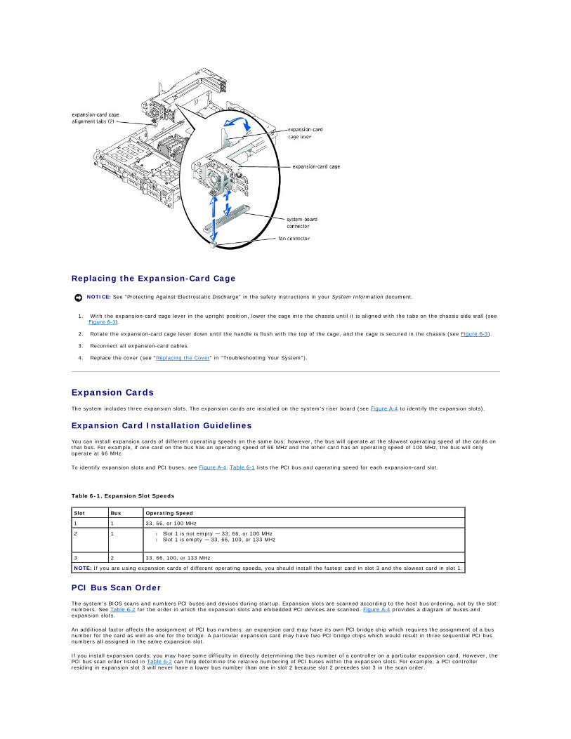
Replacing the Expansion-Card Cage
1. With the expansion-card cage lever in the upright position, lower the cage into the chassis until it is aligned with the tabs on the chassis side wall (see Figure 6-3).
2. Rotate the expansion-card cage lever down until the handle is flush with the top of the cage, and the cage is secured in the chassis (see Figure 6-3).
3. Reconnect all expansion-card cables.
4. Replace the cover (see "Replacing the Cover" in "Troubleshooting Your System").
Expansion Cards
The system includes three expansion slots. The expansion cards are installed on the system's riser board (see Figure A-4 to identify the expansion slots).
Expansion Card Installation Guidelines
You can install expansion cards of different operating speeds on the same bus; however, the bus will operate at the slowest operating speed of the cards on that bus. For example, if one card on the bus has an operating speed of 66 MHz and the other card has an operating speed of 100 MHz, the bus will only operate at 66 MHz.
To identify expansion slots and PCI buses, see Figure A-4. Table 6-1 lists the PCI bus and operating speed for each expansion-card slot.
PCI Bus Scan Order
The system's BIOS scans and numbers PCI buses and devices during startup. Expansion slots are scanned according to the host bus ordering, not by the slot numbers. See Table 6-2 for the order in which the expansion slots and embedded PCI devices are scanned. Figure A-4 provides a diagram of buses and expansion slots.
An additional factor affects the assignment of PCI bus numbers: an expansion card may have its own PCI bridge chip which requires the assignment of a bus number for the card as well as one for the bridge. A particular expansion card may have two PCI bridge chips which would result in three sequential PCI bus numbers all assigned in the same expansion slot.
If you install expansion cards, you may have some difficulty in directly determining the bus number of a controller on a particular expansion card. However, the PCI bus scan order listed in Table 6-2 can help determine the relative numbering of PCI buses within the expansion slots. For example, a PCI controller residing in expansion slot 3 will never have a lower bus number than one in slot 2 because slot 2 precedes slot 3 in the scan order.
NOTICE: See "Protecting Against Electrostatic Discharge" in the safety instructions in your System Information document.
Table 6-1. Expansion Slot Speeds
Slot Bus Operating Speed
1 1 33, 66, or 100 MHz
2 1 l Slot 1 is not empty — 33, 66, or 100 MHz l Slot 1 is empty — 33, 66, 100, or 133 MHz
3 2 33, 66, 100, or 133 MHz
NOTE: If you are using expansion cards of different operating speeds, you should install the fastest card in slot 3 and the slowest card in slot 1.

Installing an Expansion Card
1. Unpack the expansion card, and prepare it for installation.
For instructions, see the documentation accompanying the card.
2. Turn off the system, including any attached peripherals, and disconnect the system from the electrical outlet.
3. Remove the cover (see "Removing the Cover" in "Troubleshooting Your System").
4. Disconnect all expansion-card cables.
5. Remove the expansion-card cage (see "Removing the Expansion-Card Cage").
6. Position the expansion-card cage so that the riser board lies horizontally on your work surface.
7. Open the expansion-card latch (see Figure 6-4) and remove the filler bracket.
8. Install the expansion card (see Figure 6-4).
a. Position the expansion card so that the card-edge connector aligns with the expansion-card connector on the expansion-card riser board.
b. Insert the card-edge connector firmly into the expansion-card connector until the card is fully seated.
c. When the card is seated in the connector, close the expansion-card latch (see Figure 6-4).
The card guide latch closes automatically as the card is seated in the connector.
Figure 6-4. Installing an Expansion Card
Table 6-2. PCI Bus Scan Order
Order Device or Slot
1 Video
2 Embedded remote access components
3 Expansion slot 1
4 Expansion slot 2
5 Expansion slot 3
6 Integrated NIC 1
7 Integrated NIC 2
8 Integrated SCSI controller on the system board
9 Optional integrated RAID controller on the system board
NOTE: For the full name of an abbreviation or acronym used in this table, see "Abbreviations and Acronyms."
CAUTION: Before you perform this procedure, you must turn off the system and disconnect it from its power source. For more information, see "Safety First—For You and Your System" in "Troubleshooting Your System."
NOTICE: See "Protecting Against Electrostatic Discharge" in the safety instructions in your System Information document.

9. Replace the expansion-card cage (see "Replacing the Expansion-Card Cage").
10. Reconnect all expansion-card cables, including those for the new card.
See the documentation that came with the card for information about its cable connections.
11. Replace the cover (see "Replacing the Cover" in "Troubleshooting Your System").
Removing an Expansion Card
1. Turn off the system, including any attached peripherals, and disconnect the system from the electrical outlet.
2. Remove the cover (see "Removing the Cover" in "Troubleshooting Your System").
3. Disconnect all expansion-card cables.
4. Remove the expansion-card cage (see "Removing the Expansion-Card Cage").
5. Position the expansion-card cage so that the riser board lies horizontally on your work surface.
6. Release the expansion card:
a. Open the expansion-card latch (see Figure 6-4).
b. Press the release tab on the card-guide latch (see Figure 6-4).
c. Grasp the expansion card by its top corners, and carefully remove it from the expansion-card connector.
7. If you are removing the card permanently, install a metal filler bracket over the empty expansion slot opening and close the expansion-card latch.
8. Replace the expansion-card cage (see "Replacing the Expansion-Card Cage").
9. Reconnect all expansion-card cables.
10. Replace the cover (see "Replacing the Cover" in "Troubleshooting Your System").
Memory Modules
NOTE: If the expansion card you are installing is of a different operating speed as the card already installed on the same PCI bus, all expansion cards on that bus will operate at the slower speed.
CAUTION: Before you perform this procedure, you must turn off the system and disconnect it from its power source. For more information, see "Safety First—For You and Your System" in "Troubleshooting Your System."
NOTICE: See "Protecting Against Electrostatic Discharge" in the safety instructions in your System Information document.
NOTE: You must install a filler bracket over an empty expansion slot to maintain Federal Communications Commission (FCC) certification of the system. The brackets also keep dust and dirt out of the system and aid in proper cooling and airflow inside the system.

The six memory module connectors on the system board can accommodate 256 MB to 6 GB of registered memory modules. The memory module connectors are arranged in pairs which consist of three banks (DIMM A – DIMM C).
Memory Upgrade Kits
The system is upgradable to 6 GB by installing combinations of 128-, 256-, 512-MB, and 1-GB registered DDR SDRAM modules. You can purchase memory upgrade kits as needed.
Memory Module Installation Guidelines
Starting with the connector nearest the power supplies, the memory module connectors are labeled "DIMM A1" through "DIMM C2" (see Figure A-3). When you install memory modules, follow these guidelines:
l You must install memory modules in matched pairs.
l Install a pair of memory modules in connector DIMM A1 and A2 before installing a second pair in connectors B1 and B2, and so on.
Table 6-3 lists several sample memory configurations based on these guidelines.
Performing a Memory Upgrade
1. Turn off the system, including any attached peripherals, and disconnect the system from the electrical outlet.
2. Remove the cover (see "Removing the Cover" in "Troubleshooting Your System").
3. Install or replace the memory module pairs as necessary to reach the desired memory total (see "Installing Memory Modules" and "Removing Memory Modules").
See Figure A-3 to locate the memory module connectors.
4. Replace the cover (see "Replacing the Cover" in "Troubleshooting Your System").
5. Reconnect the system to its electrical outlet and turn the system on, including any attached peripherals.
After the system completes the POST routine, it runs a memory test.
The system detects that the new memory does not match the system configuration information, which is stored in NVRAM. The monitor displays an error message that ends with the following words:
Press <F1> to continue; <F2> to enter System Setup
6. Press <F2> to enter the System Setup program, and check the System Memory setting.
The system should have already changed the value in the System Memory setting to reflect the newly installed memory.
7. If the System Memory value is incorrect, one or more of the memory modules may not be installed properly. Repeat steps 1 through 6, ensuring that the memory modules are firmly seated in their connectors.
8. Run the system memory test in system diagnostics.
Installing Memory Modules
1. Turn off the system, including any attached peripherals, and disconnect the system from the electrical outlet.
NOTE: The memory modules must be PC-1600 compliant.
Table 6-3. Sample Memory Module Configurations
Total Desired Memory
DIMM A DIMM B DIMM C
1 2 1 2 1 2
256 MB 128 MB 128 MB None None None None
512 MB 256 MB 256 MB None None None None
1 GB 512 MB 512 MB None None None None
2 GB 512 MB 512 MB 512 MB 512 MB None None
2 GB 1 GB 1 GB None None None None
3 GB 1 GB 1 GB 512 MB 512 MB None None
6 GB 1 GB 1 GB 1 GB 1 GB 1 GB 1 GB
CAUTION: Before you perform this procedure, you must turn off the system and disconnect it from its power source. For more information, see "Safety First—For You and Your System" in "Troubleshooting Your System."
NOTICE: See "Protecting Against Electrostatic Discharge" in the safety instructions in your System Information document.
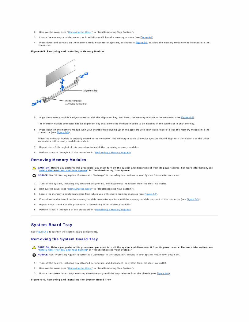
2. Remove the cover (see "Removing the Cover" in "Troubleshooting Your System").
3. Locate the memory module connectors in which you will install a memory module (see Figure A-3).
4. Press down and outward on the memory module connector ejectors, as shown in Figure 6-5, to allow the memory module to be inserted into the
connector.
Figure 6-5. Removing and Installing a Memory Module
5. Align the memory module's edge connector with the alignment key, and insert the memory module in the connector (see Figure 6-5).
The memory module connector has an alignment key that allows the memory module to be installed in the connector in only one way.
6. Press down on the memory module with your thumbs while pulling up on the ejectors with your index fingers to lock the memory module into the connector (see Figure 6-5).
When the memory module is properly seated in the connector, the memory module connector ejectors should align with the ejectors on the other connectors with memory modules installed.
7. Repeat steps 3 through 6 of this procedure to install the remaining memory modules.
8. Perform steps 4 through 8 of the procedure in "Performing a Memory Upgrade."
Removing Memory Modules
1. Turn off the system, including any attached peripherals, and disconnect the system from the electrical outlet.
2. Remove the cover (see "Removing the Cover" in "Troubleshooting Your System").
3. Locate the memory module connectors from which you will remove memory modules (see Figure A-3).
4. Press down and outward on the memory module connector ejectors until the memory module pops out of the connector (see Figure 6-5).
5. Repeat steps 3 and 4 of this procedure to remove any other memory modules.
6. Perform steps 4 through 8 of the procedure in "Performing a Memory Upgrade."
System Board Tray
See Figure A-3 to identify the system board components.
Removing the System Board Tray
1. Turn off the system, including any attached peripherals, and disconnect the system from the electrical outlet.
2. Remove the cover (see "Removing the Cover" in "Troubleshooting Your System").
3. Rotate the system board tray levers up simultaneously until the tray releases from the chassis (see Figure 6-6).
Figure 6-6. Removing and Installing the System Board Tray
CAUTION: Before you perform this procedure, you must turn off the system and disconnect it from its power source. For more information, see "Safety First—For You and Your System" in "Troubleshooting Your System."
NOTICE: See "Protecting Against Electrostatic Discharge" in the safety instructions in your System Information document.

4. Pull the system board tray straight back until it stops.
5. Lift the front of the system board tray upward slightly and then pull the tray straight back until it clears the chassis.
Replacing the System Board Tray
1. With the system board tray levers in the upright position, slide the tray into the chassis until it stops (see Figure 6-6).
2. Rotate the system board tray levers down simultaneously until the tray is secured in the chassis (see Figure 6-3).
3. Replace the cover (see "Replacing the Cover" in "Troubleshooting Your System").
Microprocessors
To take advantage of future options in speed and functionality, you can add a second microprocessor or replace either the primary or secondary microprocessor.
Each microprocessor and its associated cache memory are contained in a PGA package that is installed in a ZIF socket on the system board. A second ZIF socket accommodates a secondary microprocessor.
The following items are included in the microprocessor upgrade kit:
l A microprocessor
l A heat sink
l Two securing clips
l A cooling fan
l A VRM, if adding a second microprocessor
Adding or Replacing a Microprocessor
1. Turn off the system, including any attached peripherals, and disconnect the system from the electrical outlet.
2. Remove the cover (see "Removing the Cover" in "Troubleshooting Your System").
If you are installing a second microprocessor, go to step 6.
NOTICE: See "Protecting Against Electrostatic Discharge" in the safety instructions in your System Information document.
NOTICE: The second microprocessor must be of the same type as the first. If the two microprocessors are different speeds, both will operate at the speed of the slower microprocessor.
NOTE: In a single microprocessor system, the microprocessor must be installed in the PROC 1 socket.
CAUTION: Before you perform this procedure, you must turn off the system and disconnect it from its power source. For more information, see "Safety First—For You and Your System" in "Troubleshooting Your System."
NOTICE: See "Protecting Against Electrostatic Discharge" in the safety instructions in your System Information document.
NOTE: The system is designed to allow you to remove the microprocessor heat sink without removing the microprocessor cooling fan. However, you can remove the fan to provide easier access to the heat sink (see "Removing a Cooling Fan").

3. Remove the microprocessor heat sink:
a. Press down on the heat-sink securing clips to release the clips from the retaining tabs on the ZIF socket (see Figure 6-7).
b. Remove the heat sink securing clips.
c. Remove the heat sink.
Figure 6-7. Removing and Installing the Heat Sink
4. Pull the socket release lever straight up until the microprocessor is released (see Figure 6-8).
5. Lift the microprocessor out of the socket and leave the release lever up so that the socket is ready for the new microprocessor.
Figure 6-8. Removing and Installing the Microprocessor
6. Unpack the new microprocessor.
If any of the pins on the microprocessor appear bent, see "Getting Help" for instructions on obtaining technical assistance.
7. Ensure that the release lever on the microprocessor socket is in the upright position.
CAUTION: The microprocessor and heat sink can become extremely hot. Be sure the microprocessor has had sufficient time to cool before handling.
NOTICE: Never remove the heat sink from a microprocessor unless you intend to remove the microprocessor. The heat sink is required to maintain proper thermal conditions.
NOTICE: Be careful not to bend any of the pins when removing the microprocessor. Bending the pins can permanently damage the microprocessor.

8. Align pin 1 on the microprocessor (see Figure 6-8) with pin 1 on the microprocessor socket.
9. Install the microprocessor in the socket (see Figure 6-8).
10. When the microprocessor is fully seated in the socket, rotate the socket release lever back down until it snaps into place, securing the microprocessor.
11. Place the new heat sink on top of the microprocessor (see Figure 6-7).
12. Orient the securing clips as shown in Figure 6-7.
13. Hook the end of the clips without the latch to the tab on the edge of the socket.
14. Push down and pivot the securing clip latch until the hole on the clip latches onto the ZIF socket tab.
15. Ensure that the microprocessor cooling fan is installed:
l If you removed the microprocessor cooling fan before you removed the microprocessor heat sink, replace the fan.
l If you installed a second microprocessor, install the fan for the new microprocessor.
For information on installing or replacing a cooling fan, see "Replacing a Cooling Fan."
16. If you are adding a second microprocessor, install the VRM in the VRM 2 connector, pushing down firmly to make sure that the latches engage (see Figure 6-9).
Figure 6-9. Installing the VRM
17. Replace the cover (see "Replacing the Cover" in "Troubleshooting Your System").
18. Reconnect the system to its electrical outlet and turn the system on, including any attached peripherals.
19. Enter the System Setup program, and ensure that the microprocessor options match the new system configuration (see "Using the System Setup Program" in your User's Guide).
As the system boots, it detects the presence of the new microprocessor and automatically changes the system configuration information in the System Setup program. If you installed a second microprocessor, a message similar to the following appears:
Two 1.8 GHZ Processors, Processor Bus: 400 MHz, L2 cache 512 KB Advanced
If only one microprocessor is installed, a message similar to the following appears:
One 1.8 GHz Processor, Processor Bus: 400 MHz, L2 cache 512 KB Advanced
20. Confirm that the top line of the system data area in the System Setup program correctly identifies the installed microprocessor(s) (see "Using the System Setup Program" in your User's Guide).
21. Exit the System Setup program.
22. Run the system diagnostics to verify that the new microprocessor is operating correctly.
See "Running System Diagnostics" for information on running the diagnostics and troubleshooting any problems that may occur.
System Battery
The system battery is a 3.0-volt (V), coin-cell battery.
NOTE: No force is needed to install the microprocessor in the socket. When the microprocessor is aligned correctly, it should drop into the socket.
NOTICE: Positioning the microprocessor incorrectly can permanently damage the microprocessor and the system when you turn on the system. When placing the microprocessor in the socket, be sure that all of the pins on the microprocessor go into the corresponding holes. Be careful not to bend the pins.
NOTICE: A cooling fan is required for each microprocessor to maintain proper thermal conditions.

Replacing the System Battery
1. Turn off the system, including any attached peripherals, and disconnect the system from the electrical outlet.
2. Remove the cover (see "Removing the Cover" in "Troubleshooting Your System").
3. Remove the expansion-card cage (see "Removing the Expansion-Card Cage").
4. Remove the system battery (see Figure 6-10).
See Figure A-3 to locate the system battery on the system board.
You can pry the system battery out of its connector with your fingers or with a blunt, nonconductive object such as a plastic screwdriver.
5. Install the new system battery with the side labeled "+" facing up (see Figure 6-10).
Figure 6-10. Removing and Installing the System Battery
6. Replace the expansion-card cage (see "Replacing the Expansion-Card Cage").
7. Replace the cover (see "Replacing the Cover" in "Troubleshooting Your System").
8. Reconnect the system to its electrical outlet and turn the system on, including any attached peripherals.
9. Enter the System Setup program to confirm that the battery is operating properly (see "Using the System Setup Program," in the User's Guide).
10. Enter the correct time and date in the System Setup program's Time and Date fields.
11. Exit the System Setup program.
12. To test the newly installed battery, turn off the system and disconnect it from the electrical outlet for at least an hour.
13. After an hour, reconnect the system to its electrical outlet and turn it on.
14. Enter the System Setup program and if the time and date are still incorrect, see "Getting Help" for instructions on obtaining technical assistance.
Back to Contents Page
CAUTION: Before you perform this procedure, you must turn off the system and disconnect it from its power source. For more information, see "Safety First—For You and Your System" in "Troubleshooting Your System."
CAUTION: There is a danger of a new battery exploding if it is incorrectly installed. Replace the battery only with the same or equivalent type recommended by the manufacturer. Discard used batteries according to the manufacturer's instructions. See the System Information document for additional information.
NOTICE: See "Protecting Against Electrostatic Discharge" in the safety instructions in your System Information document.

Back to Contents Page
Installing Drives Dell™ PowerEdge™ 2650 Systems Installation and Troubleshooting Guide
SCSI Interface Cables
SCSI Configuration Information
External SCSI Tape Drive
SCSI Hard Drives
CD and Diskettes Drives
Activating the Integrated RAID Controller
Installing a RAID Controller Card
Installing a SCSI Backplane Daughter Card
Configuring the Boot Device
Your system contains up to five 1-inch SCSI hard drives. A CD drive and a diskette drive are mounted together on a tray that slides in the front panel and SCSI backplane board. This design allows the diskette and CD drives to be serviced without removing the cover or connecting and disconnecting cables. This section contains instructions for replacing these devices.
SCSI Interface Cables
SCSI interface connectors are keyed for correct insertion. Keying ensures that the pin-1 wire in the cable connects to pin 1 in the connectors on both ends. When you disconnect an interface cable, take care to grasp the cable connector, rather than the cable itself, to avoid stress on the cable.
SCSI Configuration Information
Although SCSI devices are installed in essentially the same way as other devices, their configuration requirements are different. To configure an external SCSI device, follow the guidelines in the following subsections.
SCSI ID Numbers
Each device attached to a SCSI host adapter must have a unique SCSI ID number from 0 to 15.
A SCSI tape drive is configured by default as SCSI ID 6.
Device Termination
SCSI logic requires that termination be enabled for the two devices at opposite ends of the SCSI chain and disabled for all devices in between. For internal SCSI devices, termination is configured automatically. For external SCSI devices, you should disable termination on all devices and use terminated cables. See the documentation provided with any optional SCSI device you purchase for information on disabling termination.
External SCSI Tape Drive
This subsection describes how to configure and install an external SCSI tape drive.
Installing an External SCSI Tape Drive
1. Turn off the system, including any attached peripherals, and disconnect the system from the electrical outlet.
2. Prepare the tape drive for installation.
Ground yourself by touching an unpainted metal surface on the back of the system, unpack the drive (and controller card, if applicable), and compare the jumper and switch settings with those in the drive documentation.
See "SCSI Configuration Information," for information on setting the drive's SCSI ID number and enabling termination (if required). Change any settings necessary for your system's configuration.
3. Connect the tape drive's interface cable to the external SCSI connector on the controller card.
4. Reconnect the system to its electrical outlet and turn the system on, including any attached peripherals.
5. Perform a tape backup and verification test with the drive as instructed in the software documentation that came with the drive.
NOTE: There is no requirement that SCSI ID numbers be assigned sequentially or that devices be attached to the cable in order by ID number.
NOTICE: See "Protecting Against Electrostatic Discharge" in the safety instructions in your System Information document.
SCSI Hard Drives
This subsection describes how to install and configure SCSI hard drives in the system's internal hard-drive bays.
Before You Begin
Before attempting to remove or install a drive while the system is running, see the documentation for the RAID controller card ensure that the system is configured correctly to support hot-pluggable drive removal and insertion.
SCSI hard drives are supplied in special drive carriers that fit in the hard-drive bays.
You may need to use different programs than those provided with the operating system to partition and format SCSI hard drives. See "Installing and Configuring SCSI Drivers" in the User's Guide for information and instructions.
When you format a high-capacity SCSI hard drive, allow enough time for the formatting to be completed. Long format times for these drives are normal. For example, an exceptionally large drive can take over an hour to format.
SCSI Backplane Board Configuration
The hard-drive bays provide space for up to five 1-inch SCSI hard drives. The hard drives connect to a controller on the system board or a RAID controller card through the SCSI backplane board.
The system provides several options for hard drive configurations:
l SCSI backplane daughter card (see "Installing a SCSI Backplane Daughter Card"):
¡ 1x5 configuration, without the SCSI backplane daughter card installed
¡ 2/3 split configuration, with the SCSI backplane daughter card installed
l SCSI controller:
¡ Onboard SCSI controller
¡ Optional integrated RAID controller (see "Activating the Integrated RAID Controller")
¡ RAID controller card (see "Installing a RAID Controller Card")
l Cabling:
¡ If a RAID controller card is not installed, no cables are required to use either the onboard SCSI controller or optional integrated RAID controller in either a 1x5 or 2/3 split configuration.
¡ If a RAID controller card is installed, cables can be connected from the controller card to SCSIA and/or SCSIB backplane board connector(s). A backplane board connector that is not attached to the RAID controller card will use the onboard SCSI controller or optional integrated RAID controller.
¡ If a cable is connected to the SCSIB backplane board connector, the SCSI backplane daughter card must be installed to activate the 2/3 split configuration. Otherwise, the system will display an error message.
See Figure A-5 to locate the connectors on the SCSI backplane board.
Installing a SCSI Hard Drive
1. Remove the bezel (see "Removing the Bezel" in "Troubleshooting Your System").
2. Open the hard-drive carrier handle (see Figure 7-1).
Figure 7-1. Installing a SCSI Hard-Drive
NOTE: You should only use drives that have been tested and approved for use with the SCSI backplane board.
NOTICE: Do not turn off or reboot your system while the drive is being formatted. Doing so can cause a drive failure.
NOTICE: When installing a hard drive, ensure that the adjacent drives are fully installed. Inserting a hard-drive carrier and attempting to lock its handle next to a partially installed carrier can damage the partially installed carrier's shield spring and make it unusable.
NOTICE: Not all operating systems support hot-plug drive installation. See the documentation supplied with your operating system.

3. Insert the hard-drive carrier into the drive bay (see Figure 7-1).
4. Close the hard-drive carrier handle to lock it in place.
5. Replace the bezel (see "Replacing the Bezel" in "Troubleshooting Your System").
6. Install any required SCSI device drivers (see "Installing and Configuring SCSI Drivers" in the User's Guide for information).
7. If the hard drive is new, run the SCSI controllers test in system diagnostics.
Removing a SCSI Hard Drive
1. Remove the bezel (see "Removing the Bezel" in "Troubleshooting Your System").
2. Take the hard drive offline and wait until the SCSI hard-drive indicator codes on the drive carrier signal that the drive may be removed safely (see Table 2-6).
If the drive has been online, the drive status indicator will blink green two times a second as the drive is powered down. When all indicators are off, the drive is ready for removal.
See your operating system documentation for more information on taking the hard drive offline.
3. Open the hard-drive carrier handle to release the drive (see Figure 7-1).
4. Slide the hard drive out until it is free of the drive bay (see Figure 7-1).
If you are permanently removing the hard drive, install a blank insert.
5. Replace the bezel (see "Replacing the Bezel" in "Troubleshooting Your System").
CD and Diskettes Drives
A CD drive and a diskette drive mount together on a tray that slides in the front panel and connects to the controllers on the system board through the SCSI backplane board.
Removing the CD/Diskette Drive Tray
1. Turn off the system, including any attached peripherals, and disconnect the system from its electrical outlet.
2. Remove the bezel (see "Removing the Bezel" in "Troubleshooting Your System").
3. Grasp the CD/diskette drive tray release handle and pull the tray from the system (see Figure 7-2).
4. Slide the CD/diskette drive tray out of the system.
Figure 7-2. Removing and Installing the CD/Diskette Drive Tray
NOTICE: Do not insert a hard-drive carrier and attempt to lock its handle next to a partially installed carrier. Doing so can damage the partially installed carrier's shield spring and make it unusable. Ensure that the adjacent drive carrier is fully installed.
NOTICE: Not all operating systems support hot-plug drive installation. See the documentation supplied with your operating system.

Installing the CD/Diskette Drive Tray
1. Align the CD/diskette drive tray with the opening in the front panel.
2. Press the CD/diskette drive tray release handle until the tray snaps into place (see Figure 7-2).
3. Replace the bezel (see "Replacing the Bezel" in "Troubleshooting Your System").
4. Reconnect your system and peripherals to their electrical outlets, and turn on the system.
Activating the Integrated RAID Controller
1. Turn off the system, including any attached peripherals, and disconnect the system from the electrical outlet.
2. Remove the cover (see "Removing the Cover" in "Troubleshooting Your System").
3. Push the ejectors on the RAID memory module connector down and outward to allow the memory module to be inserted into the connector (see Figure 7-3).
See Figure A-3 to locate the RAID memory module connector on the system board.
4. Align the memory module's edge connector with the alignment keys, and insert the memory module in the connector (see Figure 7-3).
The memory module connector has two alignment keys that allow the memory module to be installed in the connector in only one way.
5. Press on the memory module with your thumbs while pulling up on the ejectors with your index fingers to lock the memory module into the connector.
Figure 7-3. Installing the RAID Controller Memory Module
CAUTION: Replace the battery only with the same or equivalent type recommended by the manufacturer. Discard used batteries according to the manufacturer's instructions. See the System Information document for additional information.
CAUTION: Before you perform this procedure, you must turn off the system and disconnect it from its power source. For more information, see "Safety First—For You and Your System" in "Troubleshooting Your System."
NOTICE: See "Protecting Against Electrostatic Discharge" in the safety instructions in your System Information document.
NOTICE: To avoid possible data loss, back up all data on the hard drives before changing the mode of operation of the integrated SCSI controller from SCSI to RAID.
NOTE: The RAID controller memory module must be an unbuffered memory module, rated to run at 100 MHz or faster. Do not substitute registered memory modules such as those used for system memory.
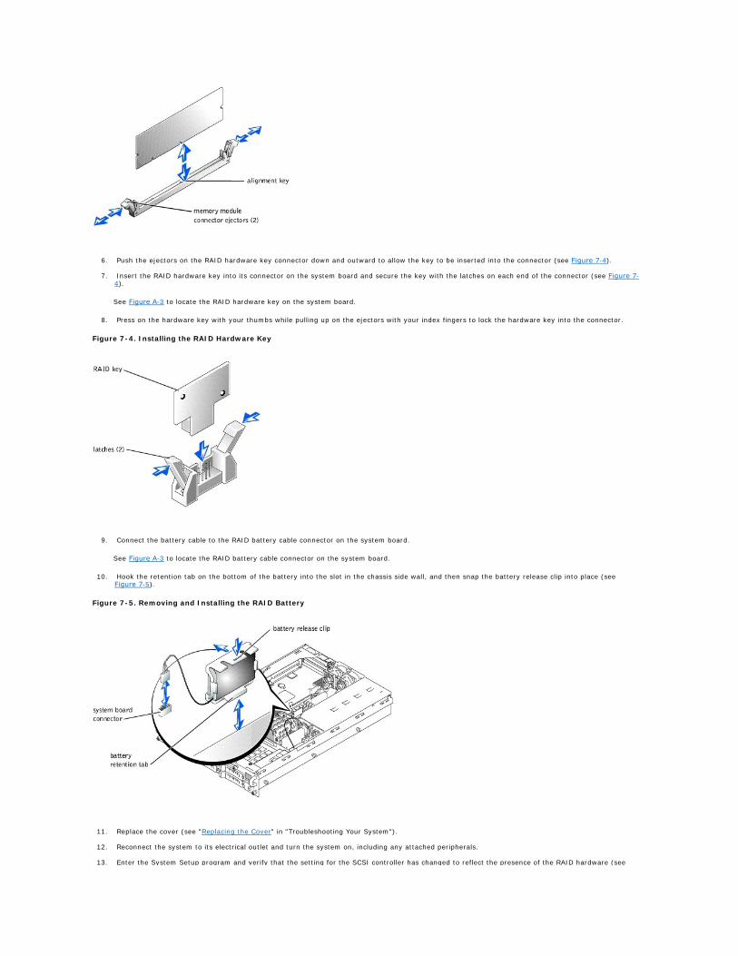
6. Push the ejectors on the RAID hardware key connector down and outward to allow the key to be inserted into the connector (see Figure 7-4).
7. Insert the RAID hardware key into its connector on the system board and secure the key with the latches on each end of the connector (see Figure 7-4).
See Figure A-3 to locate the RAID hardware key on the system board.
8. Press on the hardware key with your thumbs while pulling up on the ejectors with your index fingers to lock the hardware key into the connector.
Figure 7-4. Installing the RAID Hardware Key
9. Connect the battery cable to the RAID battery cable connector on the system board.
See Figure A-3 to locate the RAID battery cable connector on the system board.
10. Hook the retention tab on the bottom of the battery into the slot in the chassis side wall, and then snap the battery release clip into place (see Figure 7-5).
Figure 7-5. Removing and Installing the RAID Battery
11. Replace the cover (see "Replacing the Cover" in "Troubleshooting Your System").
12. Reconnect the system to its electrical outlet and turn the system on, including any attached peripherals.
13. Enter the System Setup program and verify that the setting for the SCSI controller has changed to reflect the presence of the RAID hardware (see

"Using the System Setup Program" in your User's Guide).
14. Install the RAID software.
See the RAID controller documentation for more information.
Installing a RAID Controller Card
Follow these general guidelines when installing a RAID controller card. For specific instructions, see the documentation supplied with the RAID controller card.
1. Unpack the RAID controller card, and prepare it for installation.
For instructions, see the documentation accompanying the card.
2. Turn off the system, including any attached peripherals, and disconnect the system from the electrical outlet.
3. Remove the cover (see "Removing the Cover" in "Troubleshooting Your System").
4. Install the RAID controller card (see "Installing an Expansion Card" in "Installing System Options").
5. Connect SCSI interface cables supplied with the card to the SCSIA and/or SCSIB connectors on the SCSI backplane board.
To identify the connector on the RAID controller card, see documentation for the card. See Figure A-5 to locate the SCSI controller connectors on the SCSI backplane board.
Route the SCSI cables over the SCSI backplane board to the expansion-card cage.
6. Connect the external SCSI devices to the card's external connector on the system's back panel.
If you are attaching multiple external SCSI devices, daisy-chain the devices to each other using the cables shipped with each device.
7. Replace the cover (see "Replacing the Cover" in "Troubleshooting Your System").
8. Reconnect the system to its electrical outlet and turn the system on, including any attached peripherals.
9. Install any required SCSI device drivers (see "Installing and Configuring SCSI Drivers" in the User's Guide).
10. Test the SCSI devices.
Test a SCSI hard drive by running the SCSI Controllers test in the system diagnostics.
Installing a SCSI Backplane Daughter Card
To operate the SCSI backplane in a 2/3 split backplane configuration, you must install a daughter card.
1. Unpack the SCSI backplane board daughter card kit.
2. Turn off the system, including any attached peripherals, and disconnect the system from the electrical outlet.
3. Remove the cover (see "Removing the Cover" in "Troubleshooting Your System").
4. The daughter card fits between the sides of the card guide above the drive bay. To install the daughter card in the card guide, performing the following steps:
a. Hold the daughter card by its edges with the component side facing up and the card connector facing the SCSI backplane board (see Figure 7-6).
b. Ensure that the retention lever is in the open position.
c. Position the card in the drive bay so that the notches on the left and right edges of the card are aligned with the tabs on the card guide above the drive bay.
d. Lower the card into the card guide.
e. Close the retention lever to slide the daughter card into the SCSI backplane connector and lock the card into place (see Figure 7-6).
Figure 7-6. Installing a SCSI Backplane Daughter Card
CAUTION: Before you perform this procedure, you must turn off the system and disconnect it from its power source. For more information, see "Safety First—For You and Your System" in "Troubleshooting Your System."
NOTICE: See "Protecting Against Electrostatic Discharge" in the safety instructions in your System Information document.
NOTE: Cables can be connected from the RAID controller card to SCSIA and/or SCSIB backplane board connector(s). A backplane board connector that is not attached to the RAID controller card will use the onboard SCSI controller or optional integrated RAID controller.
CAUTION: Before you perform this procedure, you must turn off the system and disconnect it from its power source. For more information, see "Safety First—For You and Your System" in "Troubleshooting Your System."
NOTICE: See "Protecting Against Electrostatic Discharge" in the safety instructions in your System Information document.
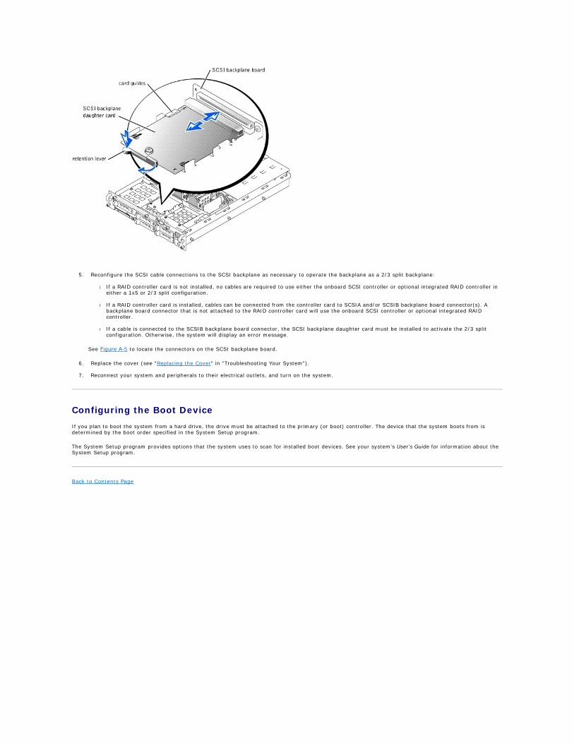
5. Reconfigure the SCSI cable connections to the SCSI backplane as necessary to operate the backplane as a 2/3 split backplane:
l If a RAID controller card is not installed, no cables are required to use either the onboard SCSI controller or optional integrated RAID controller in either a 1x5 or 2/3 split configuration.
l If a RAID controller card is installed, cables can be connected from the controller card to SCSIA and/or SCSIB backplane board connector(s). A backplane board connector that is not attached to the RAID controller card will use the onboard SCSI controller or optional integrated RAID controller.
l If a cable is connected to the SCSIB backplane board connector, the SCSI backplane daughter card must be installed to activate the 2/3 split configuration. Otherwise, the system will display an error message.
See Figure A-5 to locate the connectors on the SCSI backplane board.
6. Replace the cover (see "Replacing the Cover" in "Troubleshooting Your System").
7. Reconnect your system and peripherals to their electrical outlets, and turn on the system.
Configuring the Boot Device
If you plan to boot the system from a hard drive, the drive must be attached to the primary (or boot) controller. The device that the system boots from is determined by the boot order specified in the System Setup program.
The System Setup program provides options that the system uses to scan for installed boot devices. See your system's User's Guide for information about the System Setup program.
Back to Contents Page

Back to Contents Page
Getting Help Dell™ PowerEdge™ 2650 Systems Installation and Troubleshooting Guide
Help Overview
Dell Contact Numbers
Help Overview
This section describes the tools Dell provides to help you when you have a problem with your computer. It also tells you when and how to contact Dell for technical or customer assistance.
Technical Assistance
If you need assistance with a technical problem, perform the following steps:
1. Complete the procedures in "Troubleshooting Your System."
2. Run the system diagnostics.
3. Make a copy of the Diagnostics Checklist, and fill it out.
4. Use Dell's extensive suite of online services available at the Dell | Support website (support.dell.com) for help with installation and troubleshooting procedures.
For more information, see "World Wide Web."
5. If the preceding steps have not resolved the problem, call Dell for technical assistance.
When prompted by Dell's automated telephone system, enter your Express Service Code to route the call directly to the proper support personnel. If you do not have an Express Service Code, open the Dell Accessories folder, double-click the Express Service Code icon, and follow the directions.
For instructions on using the technical support service, see "Technical Support Service" and "Before You Call."
Help Tools
Dell provides a number of tools to assist you. These tools are described in the following sections.
World Wide Web
The Internet is your most powerful tool for obtaining information about your computer and other Dell products. Through the Internet, you can access most of the services described in this section, including AutoTech, TechFax, order status, technical support, and product information.
You can access Dell | Support at support.dell.com. Select your region on the WELCOME TO DELL SUPPORT page, and fill in the requested details to access help tools and information.
Dell can be accessed electronically using the following addresses:
l World Wide Web
www.dell.com/
www.dell.com/ap/ (for Asian/Pacific countries only)
www.euro.dell.com (for Europe only)
www.dell.com/la (for Latin American countries)
l Anonymous file transfer protocol (FTP)
ftp.dell.com/
Log in as user:anonymous, and use your e-mail address as your password.
l Electronic Support Service
[email protected] (for Asian/Pacific countries only)
support.euro.dell.com (for Europe only)
l Electronic Quote Service
NOTE: Dell's Express Service Code system may not be available in all countries.
NOTE: Some of the following tools are not always available in all locations outside the continental U.S. Please call your local Dell representative for information on availability.

[email protected] (for Asian/Pacific countries only)
l Electronic Information Service
AutoTech Service
Dell's automated technical support service—AutoTech—provides recorded answers to the questions most frequently asked by Dell customers about their portable and desktop computer systems.
When you call AutoTech, you use your touch-tone telephone to select the subjects that correspond to your questions.
The AutoTech service is available 24 hours a day, seven days a week. You can also access this service through the technical support service. For the telephone number to call, see "Dell Contact Numbers."
TechFax Service
Dell takes full advantage of fax technology to serve you better. Twenty-four hours a day, seven days a week, you can call the Dell TechFax line toll-free for all kinds of technical information.
Using a touch-tone phone, you can select from a full directory of topics. The technical information you request is sent within minutes to the fax number you designate. For the TechFax telephone number to call, see "Dell Contact Numbers."
Automated Order-Status System
You can call this automated service to check on the status of any Dell products that you have ordered. A recording prompts you for the information needed to locate and report on your order. For the telephone number to call, see "Dell Contact Numbers."
Technical Support Service
Dell's industry-leading hardware technical-support service is available 24 hours a day, seven days a week, to answer your questions about Dell hardware. Our technical support staff use computer-based diagnostics to provide fast, accurate answers to questions.
To contact Dell's technical support service, see "Before You Call" and then call the number for your country as listed in "Dell Contact Numbers."
Problems With Your Order
If you have a problem with your order, such as missing parts, wrong parts, or incorrect billing, contact Dell for customer assistance. Have your invoice or packing slip handy when you call. For the telephone number to call, see "Dell Contact Numbers."
Product Information
If you need information about additional products available from Dell, or if you would like to place an order, visit the Dell website at www.dell.com/. For the telephone number to call to speak to a sales specialist, see "Dell Contact Numbers."
Returning Items for Warranty Repair or Credit
Prepare all items being returned, whether for repair or credit, as follows:
1. Call Dell to obtain an authorization number, and write it clearly and prominently on the outside of the box.
For the telephone number to call, see "Dell Contact Numbers."
2. Include a copy of the invoice and a letter describing the reason for the return.
3. Include a copy of the Diagnostics Checklist indicating the tests you have run and any error messages reported by the system diagnostics.
4. Include any accessories that belong with the item(s) being returned (such as power cables, software floppy disks, and guides) if the return is for credit.
5. Pack the equipment to be returned in the original (or equivalent) packing materials.
You are responsible for paying shipping expenses. You are also responsible for insuring any product returned, and you assume the risk of loss during shipment to Dell. Collect-on-delivery (C.O.D.) packages are not accepted.
Returns that are missing any of the preceding requirements will be refused at our receiving dock and returned to you.
Before You Call
Remember to fill out the Diagnostics Checklist. If possible, turn on your system before you call Dell for technical assistance and call from a telephone at or near the computer. You may be asked to type some commands at the keyboard, relay detailed information during operations, or try other troubleshooting steps possible only at the computer system itself. Make sure that the system documentation is available.
NOTE: Have your Express Service Code ready when you call. The code helps Dell's automated- support telephone system direct your call more efficiently.
CAUTION: Before servicing any components inside your computer, see "Safety First—For You and Your System."
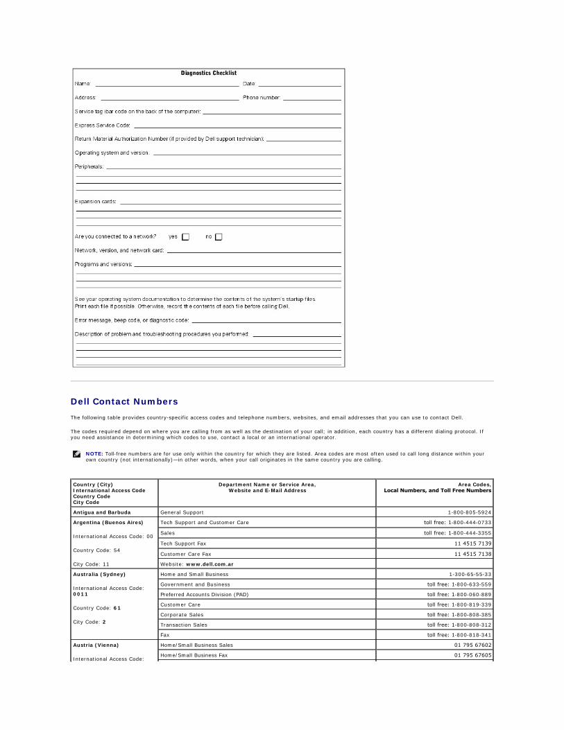
Dell Contact Numbers
The following table provides country-specific access codes and telephone numbers, websites, and email addresses that you can use to contact Dell.
The codes required depend on where you are calling from as well as the destination of your call; in addition, each country has a different dialing protocol. If you need assistance in determining which codes to use, contact a local or an international operator.
NOTE: Toll-free numbers are for use only within the country for which they are listed. Area codes are most often used to call long distance within your own country (not internationally)—in other words, when your call originates in the same country you are calling.
Country (City) International Access Code Country Code City Code
Department Name or Service Area, Website and E-Mail Address
Area Codes, Local Numbers, and Toll Free Numbers
Antigua and Barbuda General Support 1-800-805-5924
Argentina (Buenos Aires)
International Access Code: 00
Country Code: 54
City Code: 11
Tech Support and Customer Care toll free: 1-800-444-0733
Sales toll free: 1-800-444-3355
Tech Support Fax 11 4515 7139
Customer Care Fax 11 4515 7138
Website: www.dell.com.ar
Australia (Sydney)
International Access Code: 0011
Country Code: 61
City Code: 2
Home and Small Business 1-300-65-55-33
Government and Business toll free: 1-800-633-559
Preferred Accounts Division (PAD) toll free: 1-800-060-889
Customer Care toll free: 1-800-819-339
Corporate Sales toll free: 1-800-808-385
Transaction Sales toll free: 1-800-808-312
Fax toll free: 1-800-818-341
Austria (Vienna)
International Access Code:
Home/Small Business Sales 01 795 67602
Home/Small Business Fax 01 795 67605
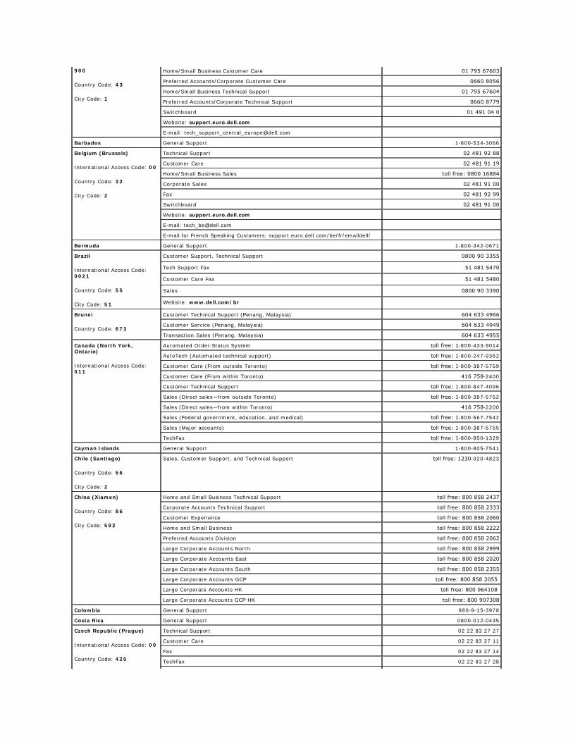
900
Country Code: 43
City Code: 1
Home/Small Business Customer Care 01 795 67603
Preferred Accounts/Corporate Customer Care 0660 8056
Home/Small Business Technical Support 01 795 67604
Preferred Accounts/Corporate Technical Support 0660 8779
Switchboard 01 491 04 0
Website: support.euro.dell.com
E-mail: [email protected]
Barbados General Support 1-800-534-3066
Belgium (Brussels)
International Access Code: 00
Country Code: 32
City Code: 2
Technical Support 02 481 92 88
Customer Care 02 481 91 19
Home/Small Business Sales toll free: 0800 16884
Corporate Sales 02 481 91 00
Fax 02 481 92 99
Switchboard 02 481 91 00
Website: support.euro.dell.com
E-mail: [email protected]
E-mail for French Speaking Customers: support.euro.dell.com/be/fr/emaildell/
Bermuda General Support 1-800-342-0671
Brazil
International Access Code: 0021
Country Code: 55
City Code: 51
Customer Support, Technical Support 0800 90 3355
Tech Support Fax 51 481 5470
Customer Care Fax 51 481 5480
Sales 0800 90 3390
Website: www.dell.com/br
Brunei
Country Code: 673
Customer Technical Support (Penang, Malaysia) 604 633 4966
Customer Service (Penang, Malaysia) 604 633 4949
Transaction Sales (Penang, Malaysia) 604 633 4955
Canada (North York, Ontario)
International Access Code: 011
Automated Order-Status System toll free: 1-800-433-9014
AutoTech (Automated technical support) toll free: 1-800-247-9362
Customer Care (From outside Toronto) toll free: 1-800-387-5759
Customer Care (From within Toronto) 416 758-2400
Customer Technical Support toll free: 1-800-847-4096
Sales (Direct sales—from outside Toronto) toll free: 1-800-387-5752
Sales (Direct sales—from within Toronto) 416 758-2200
Sales (Federal government, education, and medical) toll free: 1-800-567-7542
Sales (Major accounts) toll free: 1-800-387-5755
TechFax toll free: 1-800-950-1329
Cayman Islands General Support 1-800-805-7541
Chile (Santiago)
Country Code: 56
City Code: 2
Sales, Customer Support, and Technical Support toll free: 1230-020-4823
China (Xiamen)
Country Code: 86
City Code: 592
Home and Small Business Technical Support toll free: 800 858 2437
Corporate Accounts Technical Support toll free: 800 858 2333
Customer Experience toll free: 800 858 2060
Home and Small Business toll free: 800 858 2222
Preferred Accounts Division toll free: 800 858 2062
Large Corporate Accounts North toll free: 800 858 2999
Large Corporate Accounts East toll free: 800 858 2020
Large Corporate Accounts South toll free: 800 858 2355
Large Corporate Accounts GCP toll free: 800 858 2055
Large Corporate Accounts HK toll free: 800 964108
Large Corporate Accounts GCP HK toll free: 800 907308
Colombia General Support 980-9-15-3978
Costa Rica General Support 0800-012-0435
Czech Republic (Prague)
International Access Code: 00
Country Code: 420
Technical Support 02 22 83 27 27
Customer Care 02 22 83 27 11
Fax 02 22 83 27 14
TechFax 02 22 83 27 28

City Code: 2 Switchboard 02 22 83 27 11
Website: support.euro.dell.com
E-mail: [email protected]
Denmark (Horsholm)
International Access Code: 00
Country Code: 45
Technical Support 45170182
Relational Customer Care 45170184
Home/Small Business Customer Care 32875505
Switchboard 45170100
Fax Technical Support (Upplands Vasby, Sweden) 46 0 859005594
Fax Switchboard 45170117
Website: support.euro.dell.com
E-mail: [email protected]
E-mail Support for Servers: [email protected]
Dominican Republic General Support 1-800-148-0530
El Salvador General Support 01-899-753-0777
Finland (Helsinki)
International Access Code: 990
Country Code: 358
City Code: 9
Technical Support 09 253 313 60
Technical Support Fax 09 253 313 81
Relational Customer Care 09 253 313 38
Home/Small Business Customer Care 09 693 791 94
Fax 09 253 313 99
Switchboard 09 253 313 00
Website: support.euro.dell.com
E-mail: [email protected]
France (Paris) (Montpellier)
International Access Code: 00
Country Code: 33
City Codes: (1) (4)
Home and Small Business
Technical Support 0825 387 270
Customer Care 0825 823 833
Switchboard 0825 004 700
Switchboard (Alternative) 04 99 75 40 00
Sales 0825 004 700
Fax 0825 004 701
Fax (Alternative) 04 99 75 40 01
Website: support.euro.dell.com
E-mail: support.euro.dell.com/fr/fr/emaildell/
Corporate
Technical Support 0825 004 719
Customer Care 0825 338 339
Switchboard 01 55 94 71 00
Sales 01 55 94 71 00
Fax 01 55 94 71 01
Website: support.euro.dell.com
E-mail: support.euro.dell.com/fr/fr/emaildell/
Germany (Langen)
International Access Code: 00
Country Code: 49
City Code: 6103
Technical Support 06103 766-7200
Home/Small Business Customer Care 0180-5-224400
Global Segment Customer Care 06103 766-9570
Preferred Accounts Customer Care 06103 766-9420
Large Accounts Customer Care 06103 766-9560
Public Accounts Customer Care 06103 766-9555
Switchboard 06103 766-7000
Website: support.euro.dell.com
E-mail: [email protected]
Guatemala General Support 1-800-999-0136
Hong Kong
International Access Code: 001
Country Code: 852
Technical Support toll free: 800 96 4107
Customer Service (Penang, Malaysia) 604 633 4949
Transaction Sales toll free: 800 96 4109
Corporate Sales toll free: 800 96 4108
India Technical Support 1600 33 8045
Sales 1600 33 8044
Ireland (Cherrywood)
International Access Code: 16
Technical Support 1850 543 543
Home User Customer Care 01 204 4095

Country Code: 353
City Code: 1
Small Business Customer Care 01 204 4026
Corporate Customer Care 01 279 5011
Sales 01 204 4444
SalesFax 01 204 0144
Fax 204 5960
Switchboard 01 204 4444
Website: support.euro.dell.com
E-mail: [email protected]
Italy (Milan)
International Access Code: 00
Country Code: 39
City Code: 02
Home and Small Business
Technical Support 02 577 826 90
Customer Care 02 696 821 14
Fax 02 696 821 13
Switchboard 02 696 821 12
Website: support.euro.dell.com
E-mail: support.euro.dell.com/it/it/emaildell/
Corporate
Technical Support 02 577 826 90
Customer Care 02 577 825 55
Fax 02 575 035 30
Switchboard 02 577 821
Website: support.euro.dell.com
E-mail: support.euro.dell.com/it/it/emaildell/
Jamaica General Support 1-800-682-3639
Japan (Kawasaki)
International Access Code: 001
Country Code: 81
City Code: 44
Technical Support (Server) toll free: 0120-1984-35
Technical Support Outside of Japan (Server) 81-44-556-4152
Technical Support (Dimension™ and Inspiron™) toll free: 0120-1982-26
Technical Support Outside of Japan (Dimension and Inspiron) 81-44-520-1435
Technical Support (Dell Precision™, OptiPlex™, and Latitude™) toll free: 0120-1984-33
Technical Support Outside of Japan (Dell Precision, OptiPlex, and Latitude) 81-44-556-3894
24-Hour Automated Order Service 044 556-3801
Customer Care 044 556-4240
Business Sales Division (Up to 400 employees) 044 556 3494
Preferred Accounts Division Sales (Over 400 employees) 044 556-3433
Large Corporate Accounts Sales (Over 3500 employees) 044 556-3440
Public Sales (Government agencies, educational institutions, and medical institutions)
044 556 3440
Global Segment Japan 044 556 3469
Individual User 044 556 1657
Faxbox Service 044 556-3490
Switchboard 044 556-4300
Website: support.jp.dell.com
Korea (Seoul)
International Access Code: 001
Country Code: 82
City Code: 2
Technical Support toll free: 080-200-3800
Sales toll free: 080-200-3600
Customer Service (Seoul, Korea) toll free: 080-200-3800
Customer Service (Penang, Malaysia) 604 633 4949
Fax 2194-6202
Switchboard 2194-6000
Latin America Customer Technical Support (Austin, Texas, U.S.A.) 512 728-4093
Customer Service (Austin, Texas, U.S.A.) 512 728-3619
Fax (Technical Support and Customer Service)(Austin, Texas, U.S.A.) 512 728-3883
Sales (Austin, Texas, U.S.A.) 512 728-4397
SalesFax (Austin, Texas, U.S.A.) 512 728-4600
or 512 728-3772
Luxembourg
International Access Code: 00
Country Code: 352
Technical Support (Brussels, Belgium) 02 481 92 88
Home/Small Business Sales (Brussels, Belgium) toll free: 080016884
Corporate Sales (Brussels, Belgium) 02 481 91 00
Customer Care (Brussels, Belgium) 02 481 91 19
Fax (Brussels, Belgium) 02 481 92 99
Switchboard (Brussels, Belgium) 02 481 91 00

Website: support.euro.dell.com
E-mail: [email protected]
Macau
Country Code: 853
Technical Support toll free: 0800 582
Customer Service (Penang, Malaysia) 604 633 4949
Transaction Sales toll free: 0800 581
Malaysia (Penang)
International Access Code: 00
Country Code: 60
City Code: 4
Technical Support toll free: 1 800 888 298
Customer Service 04 633 4949
Transaction Sales toll free: 1 800 888 202
Corporate Sales toll free: 1 800 888 213
Mexico
International Access Code: 00
Country Code: 52
Customer Technical Support 001-877-384-8979
or 001-877-269-3383
Sales 50-81-8800
or 01-800-888-3355
Customer Service 001-877-384-8979
or 001-877-269-3383
Main 50-81-8800
or 01-800-888-3355
Netherlands Antilles General Support 001-800-882-1519
Netherlands (Amsterdam)
International Access Code: 00
Country Code: 31
City Code: 20
Technical Support 020 581 8838
Customer Care 020 581 8740
Home/Small Business Sales toll free: 0800-0663
Home/Small Business Sales Fax 020 682 7171
Corporate Sales 020 581 8818
Corporate Sales Fax 020 686 8003
Fax 020 686 8003
Switchboard 020 581 8818
Website: support.euro.dell.com
E-mail: [email protected]
New Zealand
International Access Code: 00
Country Code: 64
Home and Small Business 0800 446 255
Government and Business 0800 444 617
Sales 0800 441 567
Fax 0800 441 566
Nicaragua General Support 001-800-220-1006
Norway (Lysaker)
International Access Code: 00
Country Code: 47
Technical Support 671 16882
Relational Customer Care 671 17514
Home/Small Business Customer Care 23162298
Switchboard 671 16800
Fax Technical Support (Upplands Vasby, Sweden) 46 0 85 590 05 594
Fax Switchboard 671 16865
Website: support.euro.dell.com
E-mail: [email protected]
E-mail Support for Servers: [email protected]
Panama General Support 001-800-507-0962
Peru General Support 0800-50-669
Poland (Warsaw)
International Access Code: 011
Country Code: 48
City Code: 22
Customer Service Phone 57 95 700
Customer Care 57 95 999
Sales 57 95 999
Customer Service Fax 57 95 806
Reception Desk Fax 57 95 998
Switchboard 57 95 999
Website: support.euro.dell.com
E-mail: [email protected]
Portugal
International Access Code: 00
Country Code: 35
Technical Support 35 800 834 077
Customer Care 800 300 415 or 35 800 834 075
Sales 800 300 410 or 800 300 411 or 800 300 412 or

351 214 220 710
Fax 35 121 424 01 12
E-mail: support.euro.dell.com/es/es/emaildell/
Puerto Rico General Support 1-800-805-7545
St. Lucia General Support 1-800-882-1521
Singapore (Singapore)
International Access Code: 005
Country Code: 65
Technical Support toll free: 800 6011 051
Customer Service (Penang, Malaysia) 604 633 4949
Transaction Sales toll free: 800 6011 054
Corporate Sales toll free: 800 6011 053
South Africa (Johannesburg)
International Access Code: 09/091
Country Code: 27
City Code: 11
Technical Support 011 709 7710
Customer Care 011 709 7707
Sales 011 709 7700
Fax 011 706 0495
Switchboard 011 709 7700
Website: support.euro.dell.com
E-mail: [email protected]
Southeast Asian and Pacific Countries
Customer Technical Support, Customer Service, and Sales (Penang, Malaysia) 604 633 4810
Spain (Madrid)
International Access Code: 00
Country Code: 34
City Code: 91
Home and Small Business
Technical Support 902 100 130
Customer Care 902 118 540
Sales 902 118 541
Switchboard 902 118 541
Fax 902 118 539
Website: support.euro.dell.com
E-mail: support.euro.dell.com/es/es/emaildell/
Corporate
Technical Support 902 100 130
Customer Care 902 118 546
Switchboard 91 722 92 00
Fax 91 722 95 83
Website: support.euro.dell.com
E-mail: support.euro.dell.com/es/es/emaildell/
Sweden (Upplands Vasby)
International Access Code: 00
Country Code: 46
City Code: 8
Technical Support 08 590 05 199
Relational Customer Care 08 590 05 642
Home/Small Business Customer Care 08 587 70 527
Fax Technical Support 08 590 05 594
Sales 08 590 05 185
Website: support.euro.dell.com
E-mail: [email protected]
E-mail Support for Latitude and Inspiron: [email protected]
E-mail Support for OptiPlex: [email protected]
E-mail Support for Servers: [email protected]
Switzerland (Geneva)
International Access Code: 00
Country Code: 41
City Code: 22
Technical Support (Home and Small Business) 0844 811 411
Technical Support (Corporate) 0844 822 844
Customer Care (Home and Small Business) 0848 802 202
Customer Care (Corporate) 0848 821 721
Fax 022 799 01 90
Switchboard 022 799 01 01
Website: support.euro.dell.com
E-mail: [email protected]
E-mail for French Speaking HSB and Corporate Customers: support.euro.dell.com/ch/fr/emaildell/
Taiwan
International Access Code: 002
Country Code: 886
Technical Support toll free: 0080 60 1255
Technical Support (Servers) toll free: 0080 60 1256
Transaction Sales toll free: 0080 651 228
or 0800 33 556
Corporate Sales toll free: 0080 651 227

Back to Contents Page
or 0800 33 555
Thailand
International Access Code: 001
Country Code: 66
Technical Support toll free: 0880 060 07
Customer Service (Penang, Malaysia) 604 633 4949
Sales toll free: 0880 060 09
Trinidad/Tobago General Support 1-800-805-8035
U.K. (Bracknell)
International Access Code: 00
Country Code: 44
City Code: 1344
Technical Support (Corporate/Preferred Accounts/PAD [1000+ employees]) 0870 908 0500
Technical Support (Direct/PAD and general) 0870 908 0800
Global Accounts Customer Care 01344 723186
Home and Small Business Customer Care 0870 906 0010
Corporate Customer Care 01344 72 3185
Preferred Accounts (500-5000 employees) Customer Care 01344 723196
Central Government Customer Care 01344 723193
Local Government Customer Care 01344 723194
Home/Small Business Sales 0870 907 4000
Corporate/Public Sector Sales 01344 860456
Website: support.euro.dell.com
E-mail: [email protected]
U.S.A. (Austin, Texas)
International Access Code: 011
Country Code: 1
Automated Order-Status System toll free: 1-800-433-9014
AutoTech (For portable and desktop computers) toll free: 1-800-247-9362
Dell Home and Small Business Group (For portable and desktop computers):
Customer Technical Support (Return material authorization numbers) toll free: 1-800-624-9896
Customer Technical Support (Home sales purchased via www.dell.com) toll free: 1-877-576-3355
Customer Service (Credit return authorization numbers) toll free: 1-800-624-9897
National Accounts (Computers purchased by established Dell national accounts [have your account number handy], medical institutions, or value-added resellers [VARs]):
Customer Service and Technical Support (Return material authorization numbers)
toll free: 1-800-822-8965
Public Americas International (Computers purchased by governmental agencies [local, state, or federal] or educational institutions):
Customer Service and Technical Support (Return material authorization numbers)
toll free: 1-800-234-1490
Dell Sales toll free: 1-800-289-3355
or toll free: 1-800-879-3355
Spare Parts Sales toll free: 1-800-357-3355
Desktop and Portable Fee-Based Technical Support toll free: 1-800-433-9005
Sales (Catalogs) toll free: 1-800-426-5150
Fax toll free: 1-800-727-8320
TechFax toll free: 1-800-950-1329
Dell Services for the Deaf, Hard-of-Hearing, or Speech-Impaired toll free: 1-877-DELLTTY
(1-877-335-5889)
Switchboard 512 338-4400
DellNet™ Technical Support toll free: 1-877-Dellnet
(1-877-335-5638)
US Virgin Islands General Support 1-877-673-3355
Venezuela General Support 8001-3605