Dell Getting Started Guide for the S6100 ON System...
30
Dell Getting Started Guide for the S6100–ON System March 2016 Regulatory Model: S6100 Regulatory Type: S6100
Transcript of Dell Getting Started Guide for the S6100 ON System...

Dell Getting Started Guide for the S6100–ON SystemMarch 2016
Regulatory Model: S6100Regulatory Type: S6100

Notes, cautions, and warningsNOTE: A NOTE indicates important information that helps you make better use of your computer.
CAUTION: A CAUTION indicates either potential damage to hardware or loss of data and tells you how to avoid the problem.
WARNING: A WARNING indicates a potential for property damage, personal injury, or death.
© 2016 Dell Inc. All rights reserved. This product is protected by U.S. and international copyright and intellectual property laws. Dell and the Dell logo are trademarks of Dell Inc. in the United States and/or other jurisdictions. All other marks and names mentioned herein may be trademarks of their respective companies.
2016 - 03
Rev. A01

1About this GuideThis document is intended as a Getting Started Guide to get new systems up and running and ready for configuration.
For complete installation and update information, see the following documents at www.dell.com/support:Table 1. S6100–ON Documents
Information Documentation
Hardware installation and power-up instructions
Dell Installation Guide for the S6100-ON System
Software configuration Dell Configuration Guide for the S6100-ON System
Command line interface Dell Command Line Reference Guide for the S6100-ON System
Troubleshooting Open Networking (ON) Hardware Diagnostic Guide for the S6100-ON System
Latest updates Release Notes for the S6100-ON System
About this Guide 3

2Install the HardwareBefore installing the switch, verify that you meet these guidelines:
• You have enough clearance at the front of the switch so you can read the light emitting diodes (LEDs).
• The AC or DC power cord reaches from the power outlet to the Utility panel connector.
• The switch is rack-mounted before you power it up.
• Cabling is away from sources of electrical noise, such as radios, power lines, and fluorescent lighting. Ensure that the cabling is safely away from other devices that might damage the cables. If needed, allow one rack unit (RU) space between devices to provide room for cabling.
• Airflow around the switch and through the vents is unrestricted.
• Temperature around the unit does not exceed 113°F (45°C). If the switch is in a closed or multirack assembly, the temperature might be higher than normal room temperature.
• Humidity around the switch does not exceed 90 percent.
• Altitude at the installation site is below 10,000 feet.
• The switch is installed in an environment as free as possible from dust and foreign conductive material (such as metal flakes from construction activities). Cooling mechanisms, such as fans and blowers in the switch, can draw dust and other particles causing contaminant buildup inside the chassis, which can result in system malfunction.
Install the ChassisTo install the S6100–Open Networking (ON) system, Dell Networking recommends completing the installation procedures in the order presented here.
NOTE: Always handle the system and its components with care. Avoid dropping the S6100–ON chassis or its field replaceable units.
4 Install the Hardware

NOTE: For proper ventilation, position the S6100–ON chassis in an equipment rack (or cabinet) with a minimum of 5 inches (12.7 cm) of clearance around exhaust vents. The acceptable ambient temperature ranges are listed in the Technical Specifications section under Environmental Parameters.
CAUTION: Always wear an electrostatic discharge (ESD)-preventive wrist or heel ground strap when handling the S6100–ON and its components. As with all electrical devices of this type, take all necessary safety precautions to prevent injury when installing this system. ESD damage can occur if components are mishandled.
CAUTION: The S6100–ON contains two power cords. Disconnect both power cords before servicing.
CAUTION: Only trained and qualified personnel should install this equipment. Read this guide before installing and powering up the S6100–ON.
Rack Mounting Safety Considerations
• Rack mounting — You may either place the switch on a rack shelf or mount the switch directly into a 19" wide, EIA-310-E-compliant rack.
• Rack loading — Overloading or uneven loading of racks may result in shelf or rack failure, which may damage the equipment and cause personal injury. Stabilize the racks in a permanent location before loading begins. Mount the components starting at the bottom of the rack, then work to the top. Do not exceed your rack load rating.
• Power considerations — Connect only to the power source specified on the unit. When you install multiple electrical components in a rack, ensure that the total component power ratings do not exceed the circuit capabilities. Overloaded power sources and extension cords present fire and shock hazards.
• Elevated ambient temperature — If you install the equipment in a closed rack assembly, the operating temperature of the rack environment may be greater than the room ambient temperature. Use care not to exceed the 45°C maximum ambient temperature of the switch.
• Reduced air flow — Install the equipment in the rack so that you do not compromise the amount of airflow required for safe operation of the equipment.
• Reverse air flow — To ensure cool air intake and to avoid hot air blow out from the I/O panel, ensure that you have the necessary clearance.
• Reliable earthing — Maintain reliable earthing of the rack-mounted equipment. Pay particular attention to the supply connections other than the direct connections to the branch circuit; for example, the use of the power strips.
Install the Hardware 5

• Do not mount the equipment with the Utility panel facing in the downward position.
NOTE: These instructions are a condensed reference. Read the safety instructions in your Safety, Environmental, and Regulatory information booklet before you begin.
NOTE: The illustrations in this document are not intended to represent a specific switch.
Assemble in a Four-Post RackDue to the chassis weight, the S6100–ON switch does not support a two-post rack installation; you must install the S6100–ON in a four-post rack.
To install in a four-post rack, follow the instructions in your rack frame kit. In a four-post rack, the maximum distance between the front and back vertical posts is 36 inches (91.44 cm); the minimum distance is 24 inches (60.96 cm).
Mounting the Chassis in a Four-Post RackRack Mounting Safety Considerations
WARNING: To prevent bodily injury when mounting or servicing this unit in a rack, take special precautions to ensure that the system remains stable. The following guidelines are provided to ensure your safety:
• If your chassis is the only unit in the rack, mount it at the bottom of the rack.
• When mounting this unit in a partially filled rack, load the rack from the bottom to the top with the heaviest component at the bottom of the rack.
• If the rack comes with stabilizing devices, install the stabilizers before mounting or servicing the unit in the rack.
• If the chassis ships with blanks, remove the blanks from each slot before lifting the chassis.
WARNING: These instructions are a condensed reference. Read the safety instructions in your Safety, Environmental, and Regulatory information booklet before you begin.
NOTE: The illustrations in this document are not intended to represent a specific switch.
6 Install the Hardware

Installing and Removing the System
1. Align the system with the rails and slide the system into the rack.
2. Tighten the screws on each side of the systems’s front panel (1).
3. To remove the system from the rack, loosen the screws and slide the system out of the rack.
Figure 1. Installing the S6100–ON System
1. Extra screws to restrict front-back movement of the switch.
2. Main screw.
Install the Hardware 7
Securing the Chassis GroundAfter you mount the chassis, secure the chassis ground as follows:
To properly ground the chassis, Dell Networking recommends using a 6 AWG two-hole lug, #10 hole size, 63" spacing (not included in shipping). The two-hole lug must be a UL recognized, crimp-type lug. To connect the ground cable to the framework or cabinet and to mount the unit, use thread-forming unit mounting screws that remove paint or nonconductive coatings.
CAUTION: Grounding conductors must be made of copper. Do not use aluminum conductors.
NOTE: The rack installation “ears” are not suitable for grounding.
NOTE: Coat the two-hole lug with an anti-oxidant compound prior to crimping. Also, bring any unplated mating surfaces to a shiny finish and coat with an anti-oxidant prior to mating. Plated mating surfaces must be clean and free from contamination.
NOTE: Never use the same bolts to secure multiple grounding cables.
1. Locate the two-hole chassis ground connector nuts on the chassis back.
8 Install the Hardware

Figure 2. Chassis Ground Connector
2. Install the grounding cables to the ground nuts. The grounding cable must comply with your local electrical codes in size and color (typically the cable color is green or green with a yellow stripe).
NOTE: For proper ventilation, position the chassis in an equipment rack (or cabinet) with a minimum of 5 inches (12.7 cm) of clearance around exhaust vents. The acceptable ambient temperature ranges are listed in the Environmental Parameters section.
3. Tighten the M5 screws (ensure torque is between 18 and 24 inch/lbs).
4. Connect the opposite end of the grounding cable to the nearest appropriate facility grounding post.
Install the Hardware 9

Figure 3. Cable Connector
1. Two-hold cable connector high-strand-count conductor
2. Two-holes for cable (.27 ±.02 DIA)
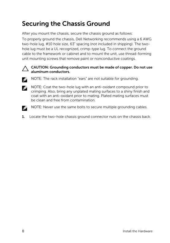
Installing an I/O ModuleTo install an I/O module, follow these steps.
WARNING: Install a blank panel in any unused switch I/O slot.
NOTE: The S6100-ON has capacitors located on the front-left corner of the PC board. To avoid damaging these capacitors when installing an I/O module, align the I/O module with the yellow arrows located inside the chassis and then gently slide the I/O module in place.
NOTE: If you remove and re-insert a module in the same slot, the system detects the module. However, if you remove a module from a slot and insert a different module into that same slot, the system does not detect the new module.
NOTE: Module power is software controlled. You will not see module LEDs when the system powers up in the Open Network Installation Environment (ONIE).
1. Remove the I/O module from the electro-static bag.
2. Open the left ejector lever (item 1) by pressing in the orange tab (item 2) and rotating it to the right so that the level snaps into the open position.
3. Slide the I/O module into the switch I/O slot.
10 Install the Hardware

The slot is keyed so that the I/O module fully inserts in only one way. When you install the I/O module correctly, it snaps into place and is flush with the back of the switch.
Figure 4. Installing an I/O Module
1. Ejector lever 2. Orange release tab
3. I/O Module
Important Points to Remember
The S6100–ON is designed to support two hot-swappable power supplies with integrated fans that provide cooling for the chassis.
• The S6100–ON ships with two power supplies.
• The PSU slides into the slot smoothly. Do not force the PSU into a slot as this action may damage the PSU or the S6100-ON chassis.
• The S6100–ON supports AC and DC power supplies with two air-flow directions (I/O to Utility and Utility to I/O). The S6100–ON does not support mixing PSU types. The fan airflow direction for the PSUs must be the same.
• Module power is software controlled. You do not see module LEDs when the system powers up.
Install the Hardware 11

CAUTION: DO NOT mix airflow directions. Both power supplies must use the same airflow direction (I/O to Utility or Utility to I/O).
WARNING: Although the switch can run on one PSU, Dell Networking highly recommends using two PSUs for full redundancy and additional cooling. To avoid overheating when the switch is running with only a single PSU, Dell Networking recommends using PSU1 (on the left) and covering the second PSU slot opening (PSU2) with a blank plate.
WARNING: ESD damage can occur if components are mishandled. Always wear an ESD-preventive wrist or heel ground strap when handling the S6100–ON and its components.
WARNING: To prevent electrical shock, ensure that the S6100–ON is grounded properly. If you ground your equipment incorrectly, excessive emissions may result. To ensure that the power cables meet your local electrical requirements, use a qualified electrician.
NOTE: The Utility panel consists of two slots, PSU1 and PSU2. Insert PSUs in both slots.
NOTE: If you remove and re-insert a module in the same slot, the system detects the module. However, if you remove a module from a slot and insert a different module into that same slot, the system does not detect the new module.
Installing AC or DC Power Supplies
1. Remove the PSU from the electro-static bag.
2. Remove the PSU slot cover from the S6100-ON.
3. Use the grab handle and orange tab to slide the PSU into the switch PSU slot. The PSU slot is keyed such that the PSU can only be fully inserted in one direction.
12 Install the Hardware

Figure 5. Install the AC or DC Power Supply Unit
1. Power supply unit 2. Release tab
4. Attach the power cables (AC 3 prong or DC wiring) from the switch PSU to the external power source.
NOTE: The system is powered-up as soon as you connect the power cord between the system and the power source.
Install the Hardware 13

Figure 6. Attach the Power Cables
5. Repeat steps 1 through 4 for the second PSU.
NOTE: Ensure that the PSU is correctly installed. When you correctly install the PSU, the power connector is on the left side of the PSU.
Connecting a DC Power Supply to the Power Source
Each DC powered system comes with a set containing a prewired (3-inch 8AWG) power supply connector and a four-screw wiring block. One set is provided for each DC PSU.
14 Install the Hardware

Figure 7. DC Power Connector and Wiring Block
1. DC wire RTN 2. DC power connector
3. Captive screws (2) 4. Orange tab
5. PSU status LED 6. DC power socket
7. DC wire –48V
Install the Hardware 15

Figure 8. DC Power Connector Ground
1. Ground nut 2. Washer
3. Lock washer 4. Ground cable
5. Device grounding rod
To connect a DC PSU to the site’s DC power source, follow these steps:
1. Strip 1/2 inches of insulation from each of the power connector’s wires, as shown.
2. Insert each of the power connector’s bare wire lengths into the wiring block, as shown.
3. Use a flat-blade screwdriver to tighten the screws that secures the bare wires into the wiring block.
4. Secure the site’s DC power source wires to the other side of the wiring block (See steps 1 and 3).
5. Insert the DC power connector into the power socket of the DC PSU. Ensure that the connector pins firmly seat and you hear the click of the power connector’s left and right levered clamps lock into place.
WARNING: Never try to force the power connector into or out of the DC PSU power socket.
16 Install the Hardware

NOTE: To remove the power connector from a DC PSU, squeeze the levers on both sides of the connector. Doing so disengages the power connector’s clamps. While continuing to squeeze, pull the power connector from the DC PSU socket.
Installing a Fan ModuleCAUTION: DO NOT mix airflow directions. All fans must use the same airflow direction (I/O to Utility or Utility to I/O).
CAUTION: Check the fans at six-month intervals and replace them as necessary. To accurately determine replacement intervals, regularly monitor the speeds of the cooling fans.
1. Remove the fan module from the shipping box.
2. Use the grab handle and the orange tab to slide the module into the switch fan slot.
Figure 9. Install the Fan Module
1. Fan module 2. Release tab
Install the Hardware 17

Installing the SFP+/QSFP OpticsThe S6100–ON can have up to 64 quad small form-factor pluggable (QSFP) optical ports that support QSFP+ and up to 32 ports that support QSFP28. The system also has two SFP+ optical ports.For a list of supported optics, contact your Dell Networking representative.
CAUTION: ESD damage can occur if the components are mishandled. Always wear an ESD-preventive wrist or heel ground strap when handling the S6100–ON and its components.
WARNING: When working with optical fibers, follow all the warning labels and always wear eye protection. Never look directly into the end of a terminated or unterminated fiber or connector as it may cause eye damage.
1. Position the optic so it is in the correct position. The optic has a key that prevents it from being inserted incorrectly.
2. Gently insert the optic into the port until it snaps into place.
NOTE: When you cable the ports, be sure not to interfere with the airflow from the small vent holes above and below the ports.
Supply Power and Power Up the SystemSupply power to the S6100–ON after the chassis is mounted in a rack.
Dell Networking recommends re-inspecting your system prior to powering up. Verify that:
• The equipment is properly secured to the rack.
• The equipment rack is properly mounted and grounded.
• The ambient temperature around the unit (which may be higher than the room temperature) is within the limits specified for the S6100–ON.
• There is sufficient airflow around the unit.
• The input circuits are correctly sized for the loads and that you use sufficient overcurrent protection devices.
• All protective covers are in place.
CAUTION: ESD damage can occur if the components are mishandled. Always wear an ESD-preventive wrist or heel ground strap when handling the S6100–ON and its components.
18 Install the Hardware

NOTE: A country/region-specific AC or DC power cable is included in the shipping container for powering up an AC or DC power supply. You must order all other power cables separately.
NOTE: Module power is software controlled. You will not see module LEDs when the system powers up in ONIE.
When the system powers up, the fans come on at high speed. The fan speed slows as the system boots up.
AC or DC Power
CAUTION: Ensure that the PSU is installed correctly. The AC or DC power connector must be on the left side of the PSU and the status LED at the top of the PSU.
Connect the plug to each AC or DC power connector. Make sure that the power cord is secure.
When you connect the cable between the S6100–ON and the power source, the switch is powered-up; there is no on/off switch.
Fan
The fan module and the integrated fan-power supply is hot-swappable.
NOTE: The S6100–ON supports two airflow direction options. You can only use a single direction in a chassis; do not mix fan flow types.
• Normal — airflow from the I/O panel to the power supply.
• Reversed — airflow from the power supply to the I/O panel.
There are environmental factors that could decrease the amount of time required between fan replacements. Check these environmental factors regularly. Any unusual environmental circumstance at the site that causes an increase in temperature and/or particulate matter in the air might affect performance (for example, new equipment installation).
After Installing the S6100–ON
After you have securely installed and powered on the S6100-ON, to configure your system, see your ONIE-compatible operating system documentation.
Install the Hardware 19

3NEBs ComplianceFor your system to be network equipment building system (NEBs) compliant, you must follow the instructions detailed in this chapter.
To be NEBs compliant, you must orient your system in the rack so that the air inlet is from the front aisle and the air exhaust is to the rear aisle.
Important Information
WARNING: The quad form-factor pluggable (QSFP), console, Ethernet management, and universal serial bus (USB) ports are suitable for connection to intra-building or unexposed wiring or cabling only. You MUST NOT metallically connect the ports to interfaces that connect to the out side plant (OSP) or its wiring. Use these interfaces as intra-building interfaces only (Type 2 or Type 4 ports as described in GR-1089-CORE, Issue 6) and they require isolation from the exposed OSP cabling. Adding primary protectors is not sufficient protection to connect these interfaces metallically to OSP wiring.
WARNING: If you install and connect the S6100-ON to a commercial AC power source, you must connect the system to an external special protection device (SPD).
To be NEBs compliant, you must follow these regulations.
• Locate your system in a restricted-access area were only trained personnel are allowed access.
• Install and connect your system to the common bonding network (CBN).
• You can also install and connect your system to the central office.
• Connect the battery returns of your system as DC-I.
• Ground your system using a copper ground conductor.
• Clean and coat all bare grounding connection points on your system with an anti-oxidant solution before making connections.
20 NEBs Compliance

• Bring all unplated surfaces on your system to a bright finish and treat them with an anti-oxidant solution before making connections.
• Remove any non-conductive surfaces on your system from the threads and connection points to ensure electrical continuity.
• Use the two-hole, Listed, compression-type lug with a AWG 14 gauge wire to secure your system to the frame.
NOTE: The S6100–ON can operate at -48 to -60 VDC at a maximum current level of 24A.
NOTE: The S6100-ON is Earthquake Z4-compliant when you attach the ReadyRails to the frame using threaded hardware.
NEBs Compliance 21

4Dell Networking OSTo initially configure the Dell Networking operating system (OS), use the following sections.
NOTE: This topic applies ONLY if you already have the Dell Networking OS installed on your system from the factory. If you are installing a third-party OS, see your third-party OS documentation.
NOTE: For complete installation and configuration information, see the following documents at www.dell.com/support:
• Dell Networking Installation Guide for the S6100–Open Networking (ON) System.
• Dell Networking Command Line Reference Guide for the S6100–Open Networking (ON) System.
• Dell Networking Configuration Guide for the S6100–Open Networking (ON) System.
• Dell Networking Release Notes for the S6100–Open Networking (ON) System.
Enter the Initial Configuration InformationTo set up the switch, assign an IP address and other configuration information necessary for the switch to communicate with the local routers and the Internet. The minimal configuration provided here does not cover most of the features; it simply allows you to perform other configuration tasks using a Telnet connection from your management network.
NOTE: To configure other features and interfaces, see the Dell Networking OS Configuration Guide for the S6100–ON System.
22 Dell Networking OS

IP Settings
To set up the switch, get the following information from your network administrator:
• Switch IP address
• Subnet mask (IP netmask)
• Default gateway (router)
• Enable secret password
• Enable password
• Telnet password
Navigating CLI ModesThe Dell Networking OS prompt changes to indicate the CLI mode.
You must move linearly through the command modes, except for the end command which takes you directly to EXEC Privilege mode and the exit command which moves you up one command mode level.
Accessing the ConsoleThe RS-232 console ports are on the left-hand side of the S6100–ON system as you face the PSU side of the chassis, as shown in the following illustration.
Figure 10. S6100–ON RS-232 Console Ports
1. Top: RJ-45 console port. Bottom: RJ-45 management port
CAUTION: Ensure that any equipment attached to the serial port can support the required 115200 baud rate.
Dell Networking OS 23

NOTE: You must have a password configured on a virtual terminal line before you can Telnet into the S6100–ON system. Therefore, use a console connection when connecting to the system for the first time. Before starting this procedure, be sure that you have a terminal emulation program already installed on your PC.
1. Install an RJ-45 copper cable into the console port. Use a rollover cable to connect the S6100–ON console port to a terminal server.
2. Connect the other end of the cable to the DTE terminal server.
3. Set the default terminal settings as follows.
• 115200 baud rate
• No parity
• 8 data bits
• 1 stop bit
• No flow control
Accessing the RJ-45 Console Port with a DB-9 AdapterYou can connect to the console using an RJ-45 to RJ-45 rollover cable and an RJ-45 to DB-9 female DTE adapter to a terminal server (for example, a PC).
The pin assignments between the console and a DTE terminal server are as follows:Table 2. Pin Assignments Between the Console and a DTE Terminal Server
S6100-ON Console Port
RJ-45 to RJ-45 Rollover Cable
RJ-45 to RJ-45 Rollover Cable
RJ-45 to DB-9 Adapter
Terminal Server Device
Signal RJ-45 Pinout RJ-45 Pinout DB-9 Pin Signal
NC 1 8 8 CTS
NC 2 7 6 DSR
TxD 3 6 2 RxD
GND 4 5 5 GND
GND 5 4 5 GND
RxD 6 3 3 TxD
24 Dell Networking OS

S6100-ON Console Port
RJ-45 to RJ-45 Rollover Cable
RJ-45 to RJ-45 Rollover Cable
RJ-45 to DB-9 Adapter
Terminal Server Device
Signal RJ-45 Pinout RJ-45 Pinout DB-9 Pin Signal
NC 7 2 4 DTR
NC 8 1 7 RTS
Default ConfigurationWhen you install the Dell Networking OS onto your S6100–ON system, it is not configured when you power up for the first time (except for the default host name, which is Dell).
You must configure the system using the CLI.
Configuring Layer 2 (Data Link) ModeTo enable Layer 2 data transmissions through an individual interface, use the switchport command in INTERFACE mode.
NOTE: For detailed information about configuring Layer 2, see the Dell Networking Configuration Guide for the Z6100-ON System.
You cannot configure switching or Layer 2 protocols such as spanning tree protocol (STP) on an interface unless the interface has been set to Layer 2 mode.
1. Enable the interface.
INTERFACE mode
no shutdown2. Place the interface in Layer 2 (switching) mode.
INTERFACE mode
switchport
To view the interfaces in Layer 2 mode, use the show interfaces switchport command in EXEC mode.
Dell Networking OS 25

Configuring a Host NameThe host name appears in the prompt. The default host name is Dell.
Host names must start with a letter, end with a letter or digit, and must have characters, letters, digits, and hyphens in the string.
• Create a host name.
CONFIGURATION mode
hostname name
Accessing the System RemotelyYou can configure the S6100–ON system to access remotely using Telnet.
The system has a dedicated management port and a management routing table that is separate from the IP routing table.
Configuring the Enable PasswordAccess EXEC Privilege mode using the enable command. EXEC Privilege mode is unrestricted by default.
As a basic security measure, configure a password. There are two types of enable passwords:
• Enable password — stores the password in the running/startup configuration using a data encryption standard (DES)-encryption method.
• Enable secret — stores the password in the running/startup configuration using a stronger, MD5-encryption method.
Dell Networking recommends using the enable secret password.
• Create a password to access EXEC Privilege mode.
CONFIGURATION mode
enable [password | secret] [level level] [encryption-type] password
26 Dell Networking OS

Creating a Port-based VLANThe default VLAN (VLAN 1) is part of the system startup configuration and does not require configuration.
To configure a port-based VLAN, create the VLAN and then add physical interfaces or port channel (LAG) interfaces to the VLAN.
• Configure a port-based VLAN (if the vlan-id is different from the Default VLAN ID) and enter INTERFACE VLAN mode.
CONFIGURATION mode
interface vlan vlan-id
After you create a VLAN, assign interfaces in Layer 2 mode to the VLAN to enable the VLAN.
To view the configured VLANs, use the show vlan command in EXEC
Privilege mode.
Connect the S6100–ON to the NetworkAfter you have completed the hardware installation and software configuration for the S6100–ON system, connect to your company network by following your company’s cabling requirements.
Dell Networking OS 27

5Technical SpecificationsThis chapter lists the S6100–ON specifications.
NOTE: Operate the system at an ambient temperature not higher than 113°F (45°C).
CAUTION: Lithium Battery Caution: To avoid the possibility of an explosion, always replace the battery correctly.
NOTE: Replace the battery only with the same or an equivalent type. Dispose of the batteries according to the manufacturer's instructions.
Table 3. S6100–ON Chassis Physical Design
Parameter Specifications
Height 3.50 inches (88.9 mm)
Width 17.1 inches (434.3 mm)
Depth 18 inches (457.2 mm)
Chassis weight with factory-installed components
44 lbs (20 kg) (with two PSUs and four I/O modules)
Rack clearance required Front: 5 inches (12.7 cm)
Back: 5 inches (12.7 cm)
Table 4. Environmental Parameters
Parameter Specifications
Operating temperature 32° to 113°F (0° to 45°C)
Operating humidity 5 to 95 percent (RH), noncondensing
Storage temperature –40° to 158°F (–40° to 70°C)
Storage and nonoperating humidity 5 to 95 percent (RH), noncondensing
Thermal output Typical: 1170.4 BTH/hr (343 W)
28 Technical Specifications

Parameter Specifications
Maximum: 3057.3 BTU/hr (896 W)
Maximum operational altitude 10,000 feet (3,048 meters)
Maximum nonoperational altitude No performance degradation to 35,000 feet (10,668 meters)
Shock Meets Bellcore Zone 4 earthquake requirements (MIL-STD-810)
Table 5. AC Power Requirements
Parameter Specifications
Power Supply 100–240 VAC 50/60 Hz
Maximum current draw per AC system
12A-6.5A @ 100VAC-240VAC
Maximum power for the PSU 1100 Watts
Typical and Maximum Power Consumption
343 Watts typical
896 Watts maximum
Table 6. DC Power Requirements
Parameter Specifications
Minimum/maximum input voltage range
−40.5 V / −48 V/ −60V
Input power at full load −40.5V/970W −48V/930W −60V/ 950W (without fan)
−40.5V/980W −48V/940W −60V/ 960W (with fan)
Input current at full load −40.5V/23.8A −48V/19.0A −60V/ 15.6A (without fan)
−40.5V/24.0A −48V/19.2A −60V/ 16.0A (with fan)
Start up VDC 39.0+/−1.5V
Start off VDC 37.5+/−1.5V
DC/DC PSU 1100W
Technical Specifications 29

Parameter Specifications
Maximum current required 32A
30 Technical Specifications