Deliverable Report D1.2 Concept Description Report
29
This project has received funding from the European Union’s Horizon 2020 research and innovation programme under grant agreement Nº 952979 Le wind Deliverable Report D1.2 Concept Description Report This project has received funding from the European Union’s Horizon 2020 research and innovation programme under grant agreement Nº 952979
Transcript of Deliverable Report D1.2 Concept Description Report

1 | 29
D1.2 – Concept Description Report PU-Public
This project has received funding from the European Union’s Horizon 2020 research and innovation programme under grant agreement Nº 952979
Le wind
Deliverable Report
D1.2 Concept Description Report
This project has received funding from the European Union’s Horizon 2020 research and innovation programme under grant agreement Nº 952979

2 | 29
D1.2 – Concept Description Report PU-Public
This project has received funding from the European Union’s Horizon 2020 research and innovation programme under grant agreement Nº 952979
D1.2 Work Package No.
WP1 Task/s No. Task 1.1
Work Package Title Floating Platform & Mooring
Linked Task/s Title Design Brief incl. O&M/Monitoring requirements, Concept Model, Sizing, Stability, Weight Control
Status Final (Draft/Final)
Dissemination level PU - Public (PU-Public RE-Restricted CO-Confidential)
Due date deliverable 2021-08-31 Submission Date 2021-08-31
Deliverable version D1.2 Concept Description Report Final version 02
Document Contributors
Deliverable responsible Dr.techn. Olav Olsen AS (OO)
Contributors Organization Reviewers Organization
Håkon S. Andersen OO Hans-Kristian Alveberg KVAE
Eirik Dufseth KVAE Gunnar Birkeland UNIT
Jonas G. Straume
Morten H. Madsen
Lars Laukeland
Trond Landbø
OO
OO
OO
OO
Document History
Version Date Comment
01 2021-07-31 Issued for Internal Review 02 2021-08-31 Final version, review comments incorporated and issued to EC

3 | 29
D1.2 – Concept Description Report PU-Public
This project has received funding from the European Union’s Horizon 2020 research and innovation programme under grant agreement Nº 952979
Table of contents
1. Executive summary ........................................................................................................................................ 7 2. Introduction ................................................................................................................................................. 10 3. Project information ..................................................................................................................................... 11 4. Concept description ..................................................................................................................................... 13 5. Floater description....................................................................................................................................... 15 6. Mooring System ........................................................................................................................................... 22 7. Cable interface ............................................................................................................................................. 24 8. Fabrication ................................................................................................................................................... 26 9. References ................................................................................................................................................... 29

4 | 29
D1.2 – Concept Description Report PU-Public
This project has received funding from the European Union’s Horizon 2020 research and innovation programme under grant agreement Nº 952979
List of figures
> Figure 1-1 The OO-Star Wind Floater, designed by Olav Olsen and 100% owned by Floating Wind Solutions AS ....................................................................................................................................................... 9 > Figure 3-1 Location of MetCentre Test Site and FLAGSHIP demonstration project................................ 12 > Figure 4-1 OO-STAR elevations. ............................................................................................................... 13 > Figure 4-2 Buoyancy Material in Pontoons ............................................................................................. 14 > Figure 4-3 Naming and terms used for various parts of the structure .................................................... 15 > Figure 5-1 From model test at SINTEF OCEAN. ....................................................................................... 16 > Figure 5-2 Key figures – base case concept. ............................................................................................ 19 > Figure 6-1 Mooring system layout ........................................................................................................... 22 > Figure 11-7 Preliminary J-tube general arrangement ............................................................................. 24 > Figure 11-8 Lower J-tube exit angle and J-tube plan view. ..................................................................... 25
List of tables
> Table 1-1 Main dimensions and Key figures .............................................................................................. 8
5 | 29
D1.2 – Concept Description Report PU-Public
This project has received funding from the European Union’s Horizon 2020 research and innovation programme under grant agreement Nº 952979
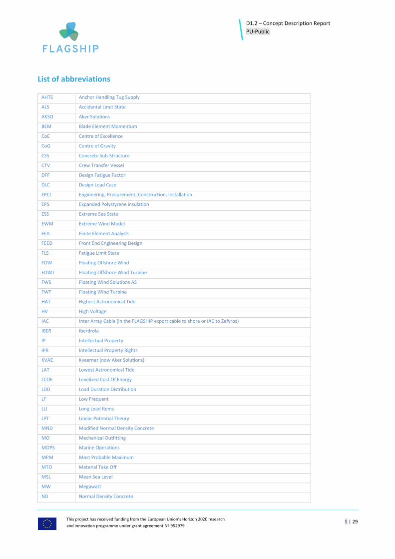
List of abbreviations
AHTS Anchor Handling Tug Supply
ALS Accidental Limit State
AKSO Aker Solutions
BEM Blade Element Momentum
CoE Centre of Excellence
CoG Centre of Gravity
CSS Concrete Sub-Structure
CTV Crew Transfer Vessel
DFF Design Fatigue Factor
DLC Design Load Case
EPCI Engineering, Procurement, Construction, Installation
EPS Expanded Polystyrene insulation
ESS Extreme Sea State
EWM Extreme Wind Model
FEA Finite Element Analysis
FEED Front End Engineering Design
FLS Fatigue Limit State
FOW Floating Offshore Wind
FOWT Floating Offshore Wind Turbine
FWS Floating Wind Solutions AS
FWT Floating Wind Turbine
HAT Highest Astronomical Tide
HV High Voltage
IAC Inter Array Cable (in the FLAGSHIP export cable to shore or IAC to Zefyros)
IBER Iberdrola
IP Intellectual Property
IPR Intellectual Property Rights
KVAE Kvaerner (now Aker Solutions)
LAT Lowest Astronomical Tide
LCOE Levelized Cost Of Energy
LDD Load Duration Distribution
LF Low Frequent
LLI Long Lead Items
LPT Linear Potential Theory
MND Modified Normal Density Concrete
MO Mechanical Outfitting
MOPS Marine Operations
MPM Most Probable Maximum
MTO Material Take Off
MSL Mean Sea Level
MW Megawatt
ND Normal Density Concrete

6 | 29
D1.2 – Concept Description Report PU-Public
This project has received funding from the European Union’s Horizon 2020 research and innovation programme under grant agreement Nº 952979
NTM Normal Turbulence Model
NSS Normal Sea State
OO Dr.techn. Olav Olsen
OO-STAR OO-Star Wind Floater
RAO Response Amplitude Operator
RNA Rotor Nacelle Assembly
RPM Rotations Per Minute
RWT Reference Wind Turbine
SCF Stress Concentration Factor
SLS Serviceability Limit State
SOV Service Offshore Vessel
SSS Severe Sea State
SWL Sea Water Level
TRL Technology Readiness Level (EU definition)
UNIT Unitech Offshore AS
ULS Ultimate Limit State
WF Wave Frequent
WTG Wind Turbine Generator
wrt. With respect to
XPS Extruded Polystyrene insulation

7 | 29
D1.2 – Concept Description Report PU-Public
This project has received funding from the European Union’s Horizon 2020 research and innovation programme under grant agreement Nº 952979
1. Executive summary The OO-Star Wind Floater technology has been developed by Dr.techn.Olav Olsen AS from late 2010 and the intellectual property rights are 100% owned by the company Floating Wind Solutions AS. The project objective is to design, build and install, and subsequently test an OO-STAR supporting an 11 MW turbine at the MetCentre demonstration site west of Karmøy, Norway. Fabrication of the floater and assembly with the tower and WTG will take place on the west coast of Norway. The mooring and export cable (or IAC) will be pre-installed at the MetCentre offshore site prior to towing the complete OO-STAR unit (including tower/WTG) from shore to the site. When arriving at the site the OO-STAR will be hooked up to the pre-laid mooring lines and the cable will be pulled in through the J-tube. The OO-STAR has been developed based on the following main principles: • Simple – understandable, simple geometry, standardization. • Safe – predictable, easy operation, fail safe, passive systems. • Robust – scaleable, able to operate in rough conditions. • Durable – durability is an important factor to obtain sustainability. • Cost effective – lowest LCOE in the long run. This document covers deliverable D1.2 to the European Commission for the FLAGSHIP project. The objective of this document is to describe the OO-STAR technology in general terms. This D1.2 is a public deliverable and hence there will be no details discussed nor presented in this report. The description has been kept at a high level and no detailed drawings have been included. Figures and sketches have been included in this report for illustrative purposes. The FLAGSHIP project is divided into 11 work packages (WPs) focusing on different tasks. The main WPs for the OO-STAR concept definition are:
• WP1 – Floating Platform and Mooring • WP2 – WTG & Control Design • WP3 – Cable and Grid Connection • WP5 – Onshore Fabrication • WP6 – Offshore Installation
D1.2 is a WP1 deliverable, but links are made to relevant work performed under the other WPs mentioned above. The OO-STAR technology is a robust design which can be utilised worldwide in different water depths, environmental conditions and for any commercial WTG type and size. It can be made in concrete or steel, or a combination of the two as a hybrid. And it can fulfil requirements from any relevant design standard. For the FLAGSHIP project a concrete OO-STAR have been selected. This gives the OO-STAR a wide market range and a high market potential. DNVGL-ST-0119 [1] is the governing standard with references to a

8 | 29
D1.2 – Concept Description Report PU-Public
This project has received funding from the European Union’s Horizon 2020 research and innovation programme under grant agreement Nº 952979
number of relevant standards. In addition, IEC standards IEC 61400-1 [2], IEC 61400-3-1 [3] and IEC TS 61400-3-2 [4] are relevant standards for offshore wind and will be used if deemed relevant for specific design elements. The fact that it can be made in concrete opens up for a high degree of local content in any project worldwide. Also, in developing countries in the future. All countries have a concrete industry and a potential for developing an industry for floating wind based on the OO-STAR technology. In Table 1-1 below the main dimensions and key figures for the OO-STAR is presented. More details are given in Figure 5-2.
> Table 1-1 Main dimensions and Key figures
Description Quantities
Wind Turbine Effect 11 MW
Rotor diameter 203 m
Turbine weight, RNA 615 tonnes
Hub height SWL + 126 m
Floater dimensions:
Overall length 71 m
Overall width 78 m
Overall height 38 m
Operation draft 21 m
Concrete Volume 5560 m3
Displacement, operation 23500 tonnes
Metacentric Height 4,8 m
The main conclusion from the FLAGSHIP preliminary design phase is that the OO-STAR is a technically feasible and robust concept for FLAGSHIP with an 11 MW WTG.

9 | 29
D1.2 – Concept Description Report PU-Public
This project has received funding from the European Union’s Horizon 2020 research and innovation programme under grant agreement Nº 952979
> Figure 1-1 The OO-Star Wind Floater, designed by Olav Olsen and 100% owned by Floating Wind Solutions AS

10 | 29
D1.2 – Concept Description Report PU-Public
This project has received funding from the European Union’s Horizon 2020 research and innovation programme under grant agreement Nº 952979
2. Introduction The OO-Star Wind Floater (OO-STAR) technology has been developed by Dr.techn. Olav Olsen AS (OO) and the intellectual property rights are 100% owned by the company Floating Wind Solutions AS (FWS). In this H2020 FLAGSHIP project OO is the designer of floater and mooring and is representing the interests of FWS through separate bi-lateral agreements. The objective of the FLAGSHIP project is to design, build and install a full scale OO-STAR demonstrator and operate the unit for two years in order to demonstrate feasibility and potential for cost effective floating offshore wind in large scale. The OO-STAR full scale demonstrator will be designed for installation at MetCentre outside Karmøy on the West Coast of Norway with an 11 MW wind turbine from a renowned WTG supplier. The OO-STAR floating substructure will be made of concrete. The FLAGSHIP project is a natural follow-up from the H2020 project Lifes50+ (H2020-LCE-2014-1-640741) where the OO-STAR was upscaled to a 10 MW floating WTG and tested as a scale model in the wave basin at SINTEF Ocean in Norway. As a consequence, the OO-STAR is currently at TRL 5. After the present FLAGSHIP project, the technology will reach TRL 7 according to the EU definition. This deliverable D1.2 presents a high-level description of the OO-STAR technology. D1.2 is a public deliverable and will hence not present any detailed results.

11 | 29
D1.2 – Concept Description Report PU-Public
This project has received funding from the European Union’s Horizon 2020 research and innovation programme under grant agreement Nº 952979
3. Project information
3.1 Brief overview of the project
The FLAGSHIP project has received a grant of 25 Million Euro from EU under the Horizon 2020 program. The overall project objective is to demonstrate a cost-effective floating wind technology at large scale (10+ MW) and validate methods for reduction of levelized cost of energy (LCOE) for future large windfarms. The project will design, fabricate, and install an 11 MW floating WTG based on the OO-STAR technology. A mooring system and a flexible inter array cable (IAC) to Zefyros (or export cable to shore) will be designed, fabricated, and installed at the MetCentre site outside Karmøy on the Norwegian West Coast. The floater, steel tower and the WTG will be fully assembled at a suitable site inshore prior to tow-out and transportation to site. At the MetCentre site the floating unit will be hooked up to the pre-installed mooring system and the cable will be pulled into the J-tubes and connected to the WTG at access deck level. The actual fabrication, assembly, transportation, and installation procedures are still under development and will be accounted for in the design. The plan is to install the FOWT end of 2022 and then test it for 2 years as a part of the FLAGSHIP project. During the test period the full-scale demonstrator will be monitored in different ways and the measurements will be compared with a number of design simulations as well as results from a digital twin prepared for replication of full-scale results. The main contents of the project are the following:
• Demonstration of the innovative floater design OO-STAR • Demonstration of innovative cable and mooring design • Development of innovative fabrication methods • Validation of design methods and design tools through digital twin • Develop cost effective mass-fabrication methods and methods for industrialization • Upscaling the design to 20 MW FOWT • Upscaling to large windfarm
3.2 Site information
The FLAGSHIP demonstrator will be installed at MetCentre outside of Karmøy in Norway. In WGS 84 the coordinates for the position of the floater are 59o 09,473’ North and 4o 59,435’ East. The site is well suited for demonstration of floating offshore wind with a water depth of approximately 200 meters. The infrastructure is to a large extent already developed as the site was developed in parallel with the Hywind Demo deployment. The OO-STAR demonstrator will be located approximately 3-4 km North-West of Hywind Demo (now named Unitech Zefyros). The environmental conditions may be defined as medium to rough with significant wave height, Hs (50 yr), approximately 13 m and associated Tp 16 seconds. And combined with a high middle wind and quite significant current.

12 | 29
D1.2 – Concept Description Report PU-Public
This project has received funding from the European Union’s Horizon 2020 research and innovation programme under grant agreement Nº 952979
> Figure 3-1 Location of MetCentre Test Site and FLAGSHIP demonstration project
3.3 Turbine
The WTG defined for the FLAGSHIP project is an 11 MW wind turbine specifically designed for floating wind.

13 | 29
D1.2 – Concept Description Report PU-Public
This project has received funding from the European Union’s Horizon 2020 research and innovation programme under grant agreement Nº 952979
4. Concept description This section describes the OO-STAR concept in general terms, and it presents the concept model developed for the FEED phase of FLAGSHIP project. The OO-STAR has been developed based on the following principles:
• Simple – understandable, simple geometry, standardization. • Safe – predictable, easy operation, fail safe, passive systems. • Robust – scaleable, able to operate in rough conditions. • Durable – future world requires sustainability. • Cost effective – lowest LCOE in the long run.
The concept is designed to provide an optimal floater for the operation phase. In addition, it solves all temporary phases without any requirements for temporary tools and equipment. The floater has ample stability during all temporary conditions and there are no critical technical “bottlenecks” during the project. The selected elevations for freeboard, flange elevation, door elevation and hub height (round figure) for the current project are shown in Figure 4-1 below.
> Figure 4-1 OO-STAR elevations.

14 | 29
D1.2 – Concept Description Report PU-Public
This project has received funding from the European Union’s Horizon 2020 research and innovation programme under grant agreement Nº 952979
The selected elevations are in accordance with requirements from WTG supplier, minimum air gap requirements defined in rules and regulations etc. The corner columns have not been designed with a positive air gap since this is not a requirement, and moreover it has been regarded as a benefit to have the highest waves flowing over the steel deck which is designed to resist up to 5 m hydrostatic pressure.
During the sizing of the FLAGSHIP OO-STAR we have introduced an innovative element with buoyancy material in one of the pontoon cells (the intermediate cell) in each pontoon. This gives an additional flexibility to the sizing of the floater since we in the operation phase is floating not only on the three corner columns and the central shaft, but also parts of the pontoons where volume and position can be selected case by case and optimised for each project and WTG-type. For the FLAGSHIP it has been beneficial to reduce volumes of the central shaft and columns and as compensation fill hatched cells (ref. Figure 4-2) with buoyancy material and tune the volume to fit the required total buoyancy at optimal draft.
For this project we have selected to use ND C55 (moderate strength) concrete for the entire substructure, based on experience from recent projects. Use of higher strength (C65 or higher) is possible but not deemed cost effective for FLAGSHIP. However, using higher strength in local areas is a possibility to be explored further. Using lighter concrete, such as MND C55 concrete (used for the Heidrun TLP back in mid 1990s), is an alternative which can be explored in the future. There are reasons to believe that use of MND concrete is less cost effective when draft restrictions are not governing. There is also an option to make the corner columns in steel to save weight and to reduce floating draft inshore. However, the inshore draft is not governing for FLAGSHIP and hence we have selected a full concrete floater for this project. The OO-STAR can be designed with damage stability by including internal compartment walls in the corner columns. However, there is no requirement for damage stability for FLAGSHIP and hence we have not included this in the FLAGSHIP-design. But the corner columns and central shaft will be designed for ship impact and hence has a high level of robustness and safety built in. Based on the use of ND concrete the OO-STAR can float with a draft of 11.4 m prior to tower and WTG installation. After assembly with tower and WTG the unit will float with a minimum draft of 13.9 m which is acceptable for this North Sea project. The steel tower/concrete shaft interface is based on a well-documented solution developed in previous OO-STAR projects.
> Figure 4-2 Buoyancy Material in Pontoons

15 | 29
D1.2 – Concept Description Report PU-Public
This project has received funding from the European Union’s Horizon 2020 research and innovation programme under grant agreement Nº 952979
A steel tower has been developed for the concept sizing and has been checked for a limited number of ULS conditions. A tower base diameter of 8.5 m was provided from the WTG supplier for a bottom fixed 11 MW turbine. For a floating solution in the North Sea, we have increased the tower base diameter to 9.0 m, and this has been accepted by the WTG supplier. The tower has been documented with sufficient ULS capacity. FLS will be documented when the WTG-controller has been verified and accepted. Based on previous projects the sizing is assumed to be quite realistic, but slightly on the conservative side. A standard catenary 3-line mooring system connected on top of the corner columns has been basis for the sizing and motions. More information is given in section 6 below. The flexible cable (IAC) will be pulled in through an external guide tube mounted on the central shaft and with a bellmouth at the lower end. The cable hang-off will be at the external access platform mounted on the top of the concrete shaft. For naming and terms for various parts of the structure see Figure 4-3 below:
> Figure 4-3 Naming and terms used for various parts of the structure
5. Floater description The OO-STAR is a concrete semisubmersible floater with a “tri-star” shaped pontoon, a central shaft and three free-standing corner columns (buckets). A tri-star pontoon has the most efficient geometry possible for connecting three corner columns and a central shaft. During operation the unit floats on the three

16 | 29
D1.2 – Concept Description Report PU-Public
This project has received funding from the European Union’s Horizon 2020 research and innovation programme under grant agreement Nº 952979
corner columns (with some trim water inside) and the central shaft (dry). The floater concept is illustrated in Figure 5-2 below, including key figures. The pontoons provide a stiff base for the shaft and columns and it provides low centre of gravity, high mass and damping during operation for optimal performance. In temporary phases the pontoon provides buoyancy and makes it possible to float with shallow draft inshore. The pontoons are made of concrete which is very robust and durable and has a high stiffness which is important for the dynamic behaviour. The corner columns provide stability during operation and they also offer dry connection for the mooring lines. The corner columns are not as highly loaded as the central shaft and the pontoons. The bottom of the corner columns is used for trim water to compensate for eccentricities in the concrete hull. The corner columns are connected with pipes to the ballast caissons in the central shaft. The corner columns are free-standing and not supported horizontally at the top. There are good reasons for this:
• Avoid heavy loaded beams in the splash zone • Avoid added weight with high CoG, which do not contribute
with buoyancy and damping • Avoid heavy loaded local areas at top of columns and shaft • Avoid additional fabrication items and details
The central shaft is made of concrete and supports the steel tower and turbine. The interface between the concrete shaft and steel tower consists of a solid steel anchor ring connected with post tensioned cables, a levelling ring and a steel T-flange welded to the tower base. The rings and T-flange can be cast or welded from plate segments, and the levelling ring and T-flange can be machined to fit together within required tolerances. The concrete shaft shall transfer the loads from the turbine down to the pontoon level. The shaft is permanently dry and has internal caissons for submersible pumps. The interface between concrete and steel is at elevation 38 m (MSL+17 m) which is considered reasonable for waves with maximum Hs=12.9 m. There are damping plates (bilge keel) around the rim of the pontoons at keel level to provide added mass and damping. This is important for reducing the motions during operation. The behaviour of the floater concept has been verified through model tests performed at Sintef Ocean in November 2017 as part of the H2020 Lifes50+ project (ref. Figure 4-4). Use of ND-concrete will make sure that there are numerous suppliers of the concrete material and reduce the material cost compared to MND-Concrete. The ND-concrete has a well-known recipe and there are no specific issues related to design or fabrication. The ND C55 concrete has a density of 2.45 t/m3
> Figure 5-1 From model test at SINTEF OCEAN.
17 | 29
D1.2 – Concept Description Report PU-Public
This project has received funding from the European Union’s Horizon 2020 research and innovation programme under grant agreement Nº 952979
unreinforced. Taking into account a reinforcement density of 350 kg/m3 (ordinary reinforcement + post-tensioned cables) the density used for reinforced concrete in the concept sizing is 2.691 t/m3. It has been decided to not include compartmentation of the corner columns. Hence the developed concept does not have damage stability if one of the corner columns is flooded. Such damage stability is not a design requirement in [1] (section 10.3) and is hence more a cost/risk issue. The risk of critical tilting or capsizing is deemed to be acceptably low for an unmanned unit. The corner columns are already designed to resist significant impacts from relevant vessels. However, it is possible without significant additional cost to further increase the robustness of the concrete cylinder walls to reduce the risk related to boat impact.
5.1 Ballast System
A simple ballast system has been designed for the OO-STAR substructure based on the principle of no active ballasting. The ballast system has the following purposes:
• Filling of the pontoons during installation • Trimming of the corner columns during installation and operation (adjustments expected to
happen only a couple of times during operation life) • Bilge system for dry shaft • Deballasting of columns and pontoons during removal.
5.2 Cathodic protection
Cathodic protection is normally required for concrete offshore units which has steel embedded into the concrete. This protection system has to take into account the amount of steel to protect and due to the fact that it is difficult to isolate the reinforcement steel from embedded steel and outfitting steel the reinforcement steel must be included in the total steel to be protected. An alternative method for corrosion protection is to use induced current. The detailing of the corrosion protection system is left for the Detail Design phase.
5.3 Reason for concrete substructure
A full concrete floater has been selected for FLAGSHIP. The OO-STAR has previously been designed in full-steel for a 3 MW floating wind turbine. A full-steel OO-STAR is also deemed feasible for larger floaters, but it is expected that concrete will become more favourable for larger units. As described above, a combination with concrete pontoons/central shaft and steel corner columns (hybrid) is possible if specific challenges related to shallow water, damage stability or similar exist. Unless there are specific reasons for selecting a steel substructure concrete will be the preferred material as this is deemed to be the most cost-efficient material with the highest potential for cost reduction due to industrialization and mass fabrication. The shipyard industry is already quite advanced and streamlined, but the concrete industry is less developed for mass fabrication and hence the potential for improvements is huge. Concrete also secures high robustness, long design life and low maintenance cost.

18 | 29
D1.2 – Concept Description Report PU-Public
This project has received funding from the European Union’s Horizon 2020 research and innovation programme under grant agreement Nº 952979
5.4 Fabrication friendliness
The concrete substructure geometry is sized for optimal performance during operation. We have also, together with the fabricator Aker Solutions, considered practical aspects related to fabrication in particular. There are also some general rules or limitations related to slipforming which we have implemented in the design:
• Minimum allowable curvature (transition) radius for a vertical profile of the wall is 25 m. For this project we have a curvature radius > 40 m.
• Maximum allowable inclination of the wall is 22 degrees. For this project we have a maximum inclination from vertical < 15 degrees.
• Changes in wall thicknesses can be sudden by adding or removing insert elements, or they can be accommodated over a height by adjusting the slipform.
• There is a limit for the ratio max/min diameter which can be slipformed without stopping and rearranging the slipform.
The OO-STAR for FLAGSHIP has a maximum diameter OD=15.2 m for the lower part of the central shaft, reducing to 9.6 m at the top. It has a 2 m vertical cylinder at the base and a 6 m vertical cylinder at the top. The transition radius (S-shape) has a height of 22 m from elevation 10.0-32.0. Wall thickness in the central shaft is 0.6 m from bottom to top. The change in diameter is handled with an adjustable slipform. The maximum inclination along the transition curve is 15 degrees. The corner columns have a constant outer diameter for optimal fabrication friendliness. This has a fabrication advantage making the slipforming of the corner columns faster and less costly.
5.5 Concept model - key figures
The OO-STAR concept developed for this project is presented in Figure 4-5 below.

19 | 29
D1.2 – Concept Description Report PU-Public
This project has received funding from the European Union’s Horizon 2020 research and innovation programme under grant agreement Nº 952979
> Figure 5-2 Key figures – base case concept.
MAIN DIMENSIONS SUMMARY
Turbine effect 11 MWRotor diameter 202,66 mTurbine total weight (top weight) 615,41 t
VERTICAL LEVELS RELATIVE TO KEEL LINEBottom (Keel line) 0 mTop of Pontoon deck 8 mOperation Draft 21,00 mTop of columns 31 mTop of tower shaft/bottom steel tower 38 mLower level Rotor 46,56 m 146,90Top of steel tower 142,20 mCoG turbine (Nacelle level) 145,94 m
Air Gap to rotor in operation draft 25,56 m
FLOATER MAIN DIMENSIONSCC-Distance column to Central tower shaft 32,50 mCC-Distance Column to Column 56,29 mColumns surface diameter 15,00 mPontoon width 17,00 m
WEIGHT SUMMARY OF CONCRETE Applied specific weight 2,691 t/m3Contingency included 7,50 %Pontoon weight 9557 tColumns weight 4658 tShaft weight 1875 tTotal concrete weight 16091 tTotal concrete volume (excl. contingency) 5562 m3
TOTAL WEIGHT SUMMARYTurbine 615 tTower 559 t 891 tTransition Piece (TP) 333 tTower internals 155 tSteel decks on columns 179 tSubstructure concrete 16091 tLost Formwork, Pontoon 150 tMechanical outfitting 275 tFixed water ballast in pontoon 3999 tVariabel water ballast in columns base 740 tVertical Mooring load 426 tTotal weight 23522 t
HYDROSTATIC DATABuoyancy floater 23522 tCoB 8,05 mCoG 15,82 mGM 4,81 mHeave period 16,48 sStatic heel angle 5,51 deg
20 | 29
D1.2 – Concept Description Report PU-Public
This project has received funding from the European Union’s Horizon 2020 research and innovation programme under grant agreement Nº 952979
5.6 Concept model
The concept model is established in a spreadsheet (Excel). The model includes all parameters necessary to give a complete description of the floater with respect to geometry, weights, structural design, hydrostatics, rigid body eigen periods, and displacement. The input parameters can be varied, and the results are instantly calculated. The concept model has been the basis for the coupled analyses performed on the floating system, including turbine, tower, substructure, and mooring system. Experience from previous projects has revealed some challenges related to the first bending mode eigenfrequency for the structure. According to DNV GL recommendations this should be minimum 10% away from the 3P frequency for the wind turbine. A lower frequency can cause resonance and will increase the fatigue damage of the turbine tower. For the OO-STAR the estimated 1st bending mode frequency has a margin of 15% compared to rated 3P. Response characteristics indicates that OO-STAR is a good support structure with minimized horizontal accelerations and movements in the WTG and tower. The reason for this is most likely a high rotation point (short arm to RNA) due to a shallow draft, mooring lines attached to the top of columns and pitch and surge response out-of-phase. These beneficial response characteristics has proven to reduce the loads and fatigue damage of the tower. Some of the main response characteristics are being calculated in the spreadsheet and are used as design control parameters. These parameters are: Displacement, stability (GM), static heel (tilt) angle under maximum static wind load, heave period and pitch period. These characteristics are required to be within certain envelope values and must be checked when the input parameters are varied. In addition, there are other response characteristics which must be verified by fully coupled time domain simulations including wave and wind loads. For these analyses the software SIMA is used. The main purpose of these analyses is to verify that the structure and the mooring system have the required strength and durability for the defined design life. Further, also the dynamic behaviour as maximum pitch angle and accelerations must satisfy the boundary values defined by the turbine vendor. The analysis model required for the time domain analysis is established automatically based on the spreadsheet and transferred to a SIMA input file. This is a very efficient and resource friendly way to perform analyses and to avoid errors when a number of different cases shall be analysed. A comprehensive quality check is then necessary only for the first analysis. For later analyses simplified quality control can be performed. The analyses may reveal that design changes are required. This may be related to the structural dynamics and strength of structure and mooring system. Concept modifications can then easily be evaluated based on new analysis runs. The main structure is defined by dimensional data as for instance diameters, wall thickness, specific material weight and contingencies. The weight and mass data are calculated and reported on a summary sheet (ref. Figure 4-5).

21 | 29
D1.2 – Concept Description Report PU-Public
This project has received funding from the European Union’s Horizon 2020 research and innovation programme under grant agreement Nº 952979
Some items are given by separate input, which include weight, CoG, and spatial extension. These are typically turbine, blades, turbine equipment, access platform, guide tubes, decks, and mooring structure. In principle, all items must be included to give correct overall weight and CoG. All equipment and secondary weights must also be included as weight items in the analysis model. In addition to establishing the concept base case, the spreadsheet is used to perform sensitivity studies such as checking different concrete types, additional or variations in concrete dimensions, variations in reinforcement quantities, changes in WTG parameters etc. The Excel/SIMA setup has been used for a number of prior commercial studies for OO-STAR and Hywind, in addition to the Hywind Tampen floating windfarm project.
5.7 Weight philosophy
Based on experience from previous conceptual studies for Oil & Gas 10 % additional weights have proven to be a good estimate for a first stage concept study for expected additional weights relative to nominal weights, related to the concrete substructure. The additional weights are related to the following:
• Tolerances on concrete density • Fabrication tolerances (on thickness) • Local geometry adjustments/non-structural concrete • Weight reserves
The OO-STAR concept is a robust, clean, and simple substructure without much outfitting. We also consider it to be a mature concept based on several studies over a number of years. Compared to the concrete offshore platforms constructed worldwide we expect less uncertainties related to the OO-STAR substructure. Hence for this concept study we have included 7.5 % additional weights in the stability calculations. It is important in the concept sizing and weight philosophy also to consider what will be the consequences of a reduced weight (or 0 % additional weights). For the OO-STAR this will never be a technical challenge as reduced weight will be compensated with additional water ballast in the columns, at approximately same elevation as the weight reduction. Small variations in the CoG will not affect OO-STAR much since the stability comes mainly from waterplane area. The only negative related to reduced weight will be that overall size could have been reduced and some money saved. The FLAGSHIP project will provide a good basis for the weight philosophy to be used in the future.

22 | 29
D1.2 – Concept Description Report PU-Public
This project has received funding from the European Union’s Horizon 2020 research and innovation programme under grant agreement Nº 952979
6. Mooring System A base case mooring system has been developed. The system is based on conventional mooring chain. The pure chain system is selected based on the need for a robust and proven base case and the fact that 200 m water depth is very suitable for chain systems. The chain system has advantages with respect to available towing, installation, available tools and equipment, procurement, and schedule. Alternative configurations will be investigated together with suppliers to evaluate the potential. The alternative solutions will be assessed both based on technical, schedule and economic feasibility. The preliminary sizing of the mooring system has been based on quasi-static analyses with correction factors for expected dynamics. The system has then been updated based on the first fully coupled simulations. Based on experience the fully coupled simulations for the idling condition are typically dimensioning for the ULS capacity of the mooring system. A maximum chain grade of R3S is used to give contingency for the fatigue damage. However, it should be noted that fatigue can still be dimensioning for the mooring and this needs to be assessed based on the production cases which are still pending due to lack of floater controller at this stage. The proposed system is either way deemed to be representative for the final mooring system.
The mooring system consists of three lines with mooring chain. The base case mooring system line configuration is given in Figure 6-1 below. The heavy top chain is needed to allow for the expected chain corrosion based on the assumed corrosion rates given in the FLAGSHIP design basis.
The following mooring system is currently Base Case for FLAGSHIP:
• 162 mm chain in the upper 50 meters of the mooring system. • 142 mm chain in the lower part of the mooring system.
> Figure 6-1 Mooring system layout
23 | 29
D1.2 – Concept Description Report PU-Public
This project has received funding from the European Union’s Horizon 2020 research and innovation programme under grant agreement Nº 952979
Both suction and drag-in anchors are deemed feasible for the MetCentre site based on the available survey and soil data from the area. The project has performed and assessment comparing the two anchor types and the conclusion is that drag-in anchors should be used for the project. The main motivation for using drag-in anchors is the cost of the anchor solution combined with the delivery time. The drag-in anchors are also more flexible with respect to when a detailed survey for the FLAGSHIP site can be performed. Such a survey is needed for the design of the suction anchors, while drag-in anchors can be chosen based on the available data in the area. The survey will still provide important information for the planning of the mooring pre-lay operation for drag-in anchors. Based on this the base case is to utilize drag-in anchors for this project.

24 | 29
D1.2 – Concept Description Report PU-Public
This project has received funding from the European Union’s Horizon 2020 research and innovation programme under grant agreement Nº 952979
7. Cable interface
7.1 J-tube for HV cable
The J-tube systems identified and defined for the CSS are as follows:
• J-tube for HV cable • Bellmouth • J-tube anchor and supports
Figure 11-7 shows an overview of the preliminary J-tube system. The dynamic HV cable analysis has not yet been performed at the time of this document issue, and the J-tube parameters and use of bellmouth must therefore be verified in the next project phase.
> Figure 11-1 Preliminary J-tube general arrangement
The lower exit elevation is chosen to bottom slab level, with a departure angle of 15 degrees towards vertical. The azimuth angle is in the center between two corner columns.

25 | 29
D1.2 – Concept Description Report PU-Public
This project has received funding from the European Union’s Horizon 2020 research and innovation programme under grant agreement Nº 952979
> Figure 11-2 Lower J-tube exit angle and J-tube plan view.
The HV cable pull-in head, bend, loads, and support distances form the basis for the minimum required J-tube size. After HV cable pull-in, the cable will be terminated at top of the J-tube. A cable weak link will be installed on top of the J-tube, which will release the cable from its termination point if an accidental event occurs. A bellmouth will be installed at the lower J-tube exit elevation and shall ensure an acceptable MBR for the HV cable. The bellmouth curvature will be suited to handle the angular displacements from the HV cable and depends on the final dynamic cable configuration. The bellmouth design needs hence to be optimized in compliance with the final dynamic analysis in the next project phase. The J-tube supports will be located on the outside of the CSS. An anchor support will be installed at the top slab elevation. The anchor will be encased in the concrete structure (part of the Civil design). The upper J-tube spool piece will be supported by the external platform. The gap between the upper spool and the J-tube spools installed underneath and supported by the concrete, introduces cable hang-off loads and weak link breakage loads directly to the external platform structure. The guide supports installed towards the CSS will be made by steel and welded to embedment plates encased in the concrete wall. A bellmouth support will be installed at the bellmouth entry. This will be designed to take the horizontal loads from the HV cable.
26 | 29
D1.2 – Concept Description Report PU-Public
This project has received funding from the European Union’s Horizon 2020 research and innovation programme under grant agreement Nº 952979
8. Fabrication & Assembly The FLAGSHIP OO-STAR substructure will be fabricated in a dry dock on the west coast of Norway. The concrete structure will be completed in the dry dock, including steel structures and outfitting. The WTG assembly may also be done in the dry dock, or alternatively alongside a quay outside the dry dock. The fabrication will utilise both conventional formwork and slipforming. Slipforming for the columns and the shaft, conventional formwork for the pontoons. The substructure will be divided into construction parts and sections allowing for an efficient re-use of tools and equipment and optimal schedule. The fabrication method for FLAGSHIP is considered to be the cost-effective solution for a one-off unit. However, for a floating windfarm with several units, fabrication in a dry dock is considered not to be cost effective. For mass fabrication a continuous production flow is required and a production line on land is considered to be the optimal solution. The Tower and WTG will be lift installed in pieces using a large crane with required weight capacity and reach. The tower will typically be lifted on to the substructure in pre-defined sections and the WTG will typically be lifted on as nacelle and rotor blades separately. However this will be determined later. Fabrication and assembly are described in more details in other deliverables under WP4 and WP5.
27 | 29
D1.2 – Concept Description Report PU-Public
This project has received funding from the European Union’s Horizon 2020 research and innovation programme under grant agreement Nº 952979
9. Transport & Installation The OO-STAR FOWT unit will be completed at the fabrication yard in protected waters. The mooring system and the flexible cable will be pre-installed at the MetCentre site and ready for pick-up. This will be done in separate campaigns allowing for efficient use of specialised vessels and tools. The FOWT will be towed to site including the upper line segment already connected to the corner columns, using one or two standard AHTS of medium size. When arriving at the site the first two lines will be connected to the pre-installed lines on the deck of the AHTS. The third line will be connected using a subsea inline tensioner in order to tension the system to the required pre-tension. After hook-up with the mooring lines the cable will be pulled in through the J-tube and up to the hang-off at the access platform level. Special purpose winches and sheeves will be used for this purpose. Transport and Installation is described in more details in other deliverables under WP6.

28 | 29
D1.2 – Concept Description Report PU-Public
This project has received funding from the European Union’s Horizon 2020 research and innovation programme under grant agreement Nº 952979
10. Operation & Maintenance The OO-STAR FOWT is a very robust and durable design which will require limited operation activity and maintenance related to the floater itself. The concrete floater is “maintenance free” and only limited maintenance work is required for outfitting steel an equipment. The WTG will require the usual amount of operation and maintenance work. The ballast system is passive and temporary pumps will be used when required for adjustments of the trim water in the columns or drainage of the central shaft. This will only happen a few times during the operational life, and mainly due to marine growth on the hull. The access to the FLAGSHIP unit will be by moderate size CTV accessing the central shaft in between the columns. For the FLAGSHIP project there will be one boat access only as we consider the requirement for access to this demonstration unit to be quite limited and less critical than for a commercial windfarm. The picture below shows two boat landings and two J-tubes. Hence it is not fully representative for the FLAGSHIP unit which will have one bota landing on one side and a J-tube on the opposite side.
29 | 29
D1.2 – Concept Description Report PU-Public
This project has received funding from the European Union’s Horizon 2020 research and innovation programme under grant agreement Nº 952979
11. References [1] DNVGL, “DNVGL-ST-0119 Floating Wind Turbine Structures,” DNVGL, July 2018.
[2] IEC Standard 61400-1 Ed. 3, “Wind Turbines - Part 1: Design Requirements,” IEC, 2005.
[3] IEC, “IEC Standard 61400-3-1:2019 Wind energy generation systems - Part 3-1: Design requirements for fixed offshore wind turbines.,” 2019.
[4] IEC, “IEC TS 61400-3-2 Wind energy generation systems - Part 3-2: Design requirements for floating offshore wind turbines,” 2019.