Deliverable D2.2: Specifications of tests accelerated ... · 3.3 Test Sequence ... used for NPP...
32
Deliverable D2.2: Specifications of tests - accelerated ageing protocol, test strategy WP2: Cable provision and ageing Grant Agreement number: 755183 NFRP-2016-2017-1 Euratom programme Research and Innovation Action Start date of project: 1 st September 2017 Duration: 54 months Lead beneficiary of this deliverable: UJV Dissemination Level: Public Document type: Report Due date of deliverable: 28/02/2018 Actual submission date: 28/02/2018 Author(s) of this deliverable: Pavel Zak, Vit Placek Description: Detailed protocol how the samples will be prepared for ageing, ageing execution, explain ageing parameters, the first version of test matrix for sample sending, properties testing during ageing.
Transcript of Deliverable D2.2: Specifications of tests accelerated ... · 3.3 Test Sequence ... used for NPP...

Deliverable D2.2: Specifications of tests - accelerated ageing
protocol, test strategy
WP2: Cable provision and ageing
Grant Agreement number: 755183 NFRP-2016-2017-1
Euratom programme Research and Innovation Action
Start date of project: 1st September 2017 Duration: 54 months
Lead beneficiary of this deliverable: UJV
Dissemination Level: Public Document type: Report
Due date of deliverable: 28/02/2018 Actual submission date: 28/02/2018
Author(s) of this deliverable: Pavel Zak, Vit Placek
Description: Detailed protocol how the samples will be prepared for ageing, ageing execution, explain ageing parameters, the first version of test matrix for sample sending, properties testing during ageing.

TMC-D2.2-SPECIFICATIONS_OF_tests-F.docx
TEAM CABLES – 755183 28/02/2018
Public Copyright TeaM Cables consortium Page 2 / 32
Table of Contents
Glossary ................................................................................................................................................... 4
1 Executive Summary ......................................................................................................................... 5
2 Introduction ..................................................................................................................................... 6
3 Ageing Test Program ....................................................................................................................... 7
3.1 Test Samples ............................................................................................................................ 7
3.1.1 Tape ................................................................................................................................. 8
3.1.2 Dumb-bells ...................................................................................................................... 8
3.1.3 Sheet ................................................................................................................................ 8
3.1.4 Cables .............................................................................................................................. 9
3.1.5 Raw material .................................................................................................................. 10
3.2 Sample Identification ............................................................................................................ 11
3.3 Test Sequence ....................................................................................................................... 13
3.4 Ageing Types .......................................................................................................................... 13
3.5 Visual Inspection ................................................................................................................... 15
3.6 Diagnostic Methods ............................................................................................................... 15
3.7 Accelerated Thermal Ageing ................................................................................................. 17
3.8 Radiation Ageing.................................................................................................................... 17
3.9 Irradiation for EPR Measurement ......................................................................................... 18
3.10 LOCA and Severe Accident .................................................................................................... 18
4 Samples Storage and Samples Shipment ...................................................................................... 19
5 Documentation Plan ...................................................................................................................... 20
5.1 Progress Reports ................................................................................................................... 20
5.2 Quality Assurance .................................................................................................................. 20
6 Conclusion ..................................................................................................................................... 21
Annex A Ageing Procedures ............................................................................................................. 22
A.1 UJV Ageing Procedure ........................................................................................................... 22
A.1.1 Simultaneous Thermal and Radiation Ageing at Low Dose Rate .................................. 22
A.1.2 Radiation Ageing at Low Dose Rate ............................................................................... 24
A.1.3 Radiation Ageing at Medium Doses .............................................................................. 24
A.1.4 Radiation Ageing at High Dose Rate .............................................................................. 25
A.2 ENSAM Thermal Ageing Procedure ....................................................................................... 26
A.3 INCT irradiation procedure .................................................................................................... 26
Annex B Samples Distribution ......................................................................................................... 28
B.1 Long Cables (aged in UJV) ...................................................................................................... 28
B.2 Short Cable (aged in UJV) ...................................................................................................... 28

TMC-D2.2-SPECIFICATIONS_OF_tests-F.docx
TEAM CABLES – 755183 28/02/2018
Public Copyright TeaM Cables consortium Page 3 / 32
B.3 Tape (aged in UJV) ................................................................................................................. 28
B.4 Dumb-bells (aged in UJV) ...................................................................................................... 29
B.5 Sheet (aged in UJV) ................................................................................................................ 29
B.5.1 Initial measurement ...................................................................................................... 29
B.5.2 All other measurements (partial withdrawal) ............................................................... 29
B.5.3 All other measurements (whole irradiation) ................................................................. 29
B.6 ENSAM ................................................................................................................................... 29
B.6.4 Short Cables (thermally aged in ENSAM) ...................................................................... 29
B.6.5 Tapes (thermally aged in ENSAM) ................................................................................. 30
B.6.6 Dumb-bells (thermally aged in ENSAM) ........................................................................ 30
B.6.7 Sheets (thermally aged in ENSAM) ................................................................................ 30
Annex C Delivery Addresses ............................................................................................................ 31

TMC-D2.2-SPECIFICATIONS_OF_tests-F.docx
TEAM CABLES – 755183 28/02/2018
Public Copyright TeaM Cables consortium Page 4 / 32
Glossary
Abbreviation/ acronym
Description
ATH Alumina Trihydrate
DBE Design Basis Events
DLO Diffusion Limited Oxidation
EAB Elongation At Break
FDR Frequency Domain Reflectometry
FTIR Fourier Transformation Infrared
IM Indenter Modulus
IR Insulation resistance
LOCA Loss of Coolant Accident
LV Low Voltage
MS Mass Spectrometry
OIT Oxidative Induction Time
OITp Oxidative Induction Temperature
PHR Part per hundred of resin
PE Polyethylene
TDR Time Domain Reflectometry
TGA Thermogravimetric Analysis

TMC-D2.2-SPECIFICATIONS_OF_tests-F.docx
TEAM CABLES – 755183 28/02/2018
Public Copyright TeaM Cables consortium Page 5 / 32
1 Executive Summary
The report presents a detailed description of all parameters of the samples ageing.
Test samples will include tapes, dumb-bells, sheets, different types of cables (coaxial, twisted-pair, short and long) and raw material such as additives. Samples will be marked with a clear identification before ageing. A specific sequence has been defined for the tests. Samples will be subjected to thermal ageing, radiation ageing and simultaneous thermal and radiation ageing. Visual inspection will be performed and various diagnostic methods will be used.
In ENSAM laboratory, thermal ageing will be performed with three different combinations of temperature and time periods. ÚJV Řež laboratory will simulate radiation ageing at three different dose rates and one combination of thermal and radiation ageing. INCT will perform irradiation for EPR measurement.
Aged samples will be stored and shipped in polyethylene bags, following a different procedure depending on the type of ageing.
All activities performed will be detailed in progress reports and subjected a Quality Assurance process.

TMC-D2.2-SPECIFICATIONS_OF_tests-F.docx
TEAM CABLES – 755183 28/02/2018
Public Copyright TeaM Cables consortium Page 6 / 32
2 Introduction
This document is the second deliverable of WP2 in the TeaM CABLES project.
The aim of this document is to set up all the parameters of the samples ageing. Within the TeaM Cables project, seven types of ageing procedures will be performed in UJV Řež and ENSAM laboratories.
The document describes first how the different samples will be prepared for each type of ageing. It continues with the detailed specification of all the types of ageing that will be performed in ÚJV Řež and ENSAM laboratories. Then the samples storage properties and the matrix for sample shipment are presented. The last chapter provides the documentation plan.

TMC-D2.2-SPECIFICATIONS_OF_tests-F.docx
TEAM CABLES – 755183 28/02/2018
Public Copyright TeaM Cables consortium Page 7 / 32
3 Ageing Test Program
The ageing test program for these samples will be performed according to the criteria established in the sections that follow. This document has been issued before the samples have arrived to the laboratory and before the deliverable 2.1 “Material and cable samples” has been finalised.
3.1 Test Samples
The list of materials is only orientation. More detailed descriptions will be published in deliverable D2.1 led by NEXANS.
Tab. I: Sample description.
Form of the sample Dimension Material
1 tape/sheet/dumb-bells
Tape: width 50 mm and thickness 0.5 mm Sheet: (80×80×1) mm Dumb-bells: Size acc. IEC 60811-501
Silane crosslinked PE
2 tape/sheet/dumb-bells Silane crosslinked PE + 1phr of a phenolic antioxidant
3 tape/sheet/dumb-bells Silane crosslinked PE + 1phr of a thioether antioxidant
4 tape/sheet/dumb-bells
Silane crosslinked PE + 1phr of a phenolic antioxidant + 1phr of a thioether antioxidant
5 tape/sheet/dumb-bells Silane crosslinked PE + 25phr of ATH
6 tape/sheet/dumb-bells Silane crosslinked PE + 50phr of ATH
7 tape/sheet/dumb-bells
Silane crosslinked PE + 50phr of ATH + 1phr of a phenolic antioxidant + 1phr of a thioether antioxidant
8 Cable – coaxial cable (50 Ω)
LSZH jacket, the same that is used for NPP cable XLPE insulation, not filled, just antioxidant and stabiliser (material No 4)
9 Cable – twisted pairs cable (3×2×1 mm)
LSZH jacket outer, standard NPP material Pair 1: XLPE insulation, not filled, just antioxidant and stabiliser XLPE (material No 4) Pair 2: XLPE insulation + antioxidant + ATH (material No 7) Pair 3: EVA/EPDM

TMC-D2.2-SPECIFICATIONS_OF_tests-F.docx
TEAM CABLES – 755183 28/02/2018
Public Copyright TeaM Cables consortium Page 8 / 32
Ingredients used in the samples are:
LLDPE: PE 318 CNJ from SABIC
Silane crosslinking with VTMO/DCP
Phenolic antioxidant: Irganox 1076 from BASF
Thioether antioxidant: Hostanox 4SE from Clariant
ATH: Alolt 60 from MAL
EVA/EPDM proposal: EVA(14%)/EPDM(5% ENB;85% PE)(80/20)-DCP
3.1.1 Tape
The tape will be fabricated with a dimension of 50 mm width, 0.5 mm thick and 80 mm long tape (100 mm if enough material is available). Due to the possible DLO effect and for the dielectric spectroscopy measurements, a thin sample is required.
Fig. 1: Dimension of tape samples.
3.1.2 Dumb-bells
To avoid possible problems with sample cutting from aged tapes, NEXANS will prepare all the dumb-bell samples themselves. Size will be in accordance with the standard IEC 60811-501 (see Fig. 2). The thickness of the sample will be 0.5 mm.
Fig. 2: Dimension of dumb-bell according to the standard IEC 60811-501.
3.1.3 Sheet
Samples will also be prepared in the form of sheets with a dimension of (80 × 80 × 1) mm. These samples will be manufactured for measurements method, where tape with thickness 0.5 mm is not thick enough.
TMC-D2.2-SPECIFICATIONS_OF_tests-F.docx
TEAM CABLES – 755183 28/02/2018
Public Copyright TeaM Cables consortium Page 9 / 32
Fig. 3: Dimension of sheet samples.
3.1.4 Cables
Two cable samples will be used within the TeaM Cables project. There will be a coaxial cable and twisted pair cable. NEXANS will manufacture cable samples according to the diagram in the Fig. 4 and Fig. 5.
The samples lengths are estimative. The real length will be established at the moment of ageing by each ageing facility.
The ends of cables will be protected by self-heat sealing repair tape (Den Braven).
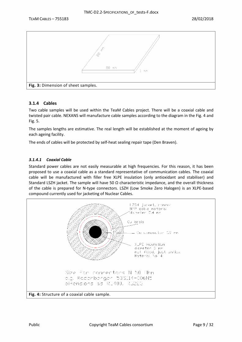
3.1.4.1 Coaxial Cable
Standard power cables are not easily measurable at high frequencies. For this reason, it has been proposed to use a coaxial cable as a standard representative of communication cables. The coaxial cable will be manufactured with filler free XLPE insulation (only antioxidant and stabiliser) and Standard LSZH jacket. The sample will have 50 Ω characteristic impedance, and the overall thickness of the cable is prepared for N-type connectors. LSZH (Low Smoke Zero Halogen) is an XLPE-based compound currently used for jacketing of Nuclear Cables.
Fig. 4: Structure of a coaxial cable sample.

TMC-D2.2-SPECIFICATIONS_OF_tests-F.docx
TEAM CABLES – 755183 28/02/2018
Public Copyright TeaM Cables consortium Page 10 / 32
3.1.4.2 Twisted-pair Cable
As the second type of the project cable shall be representative of any power/multi-core communication cables, a twisted-pair cable has been choosen. To increase the number of the electrical measurement method, the configuration of this cable is the following: twisted-pair cable with double screening and three twisted pairs, each pair made from a different insulation material:
the first pair will be made with insulation from XLPE insulation, not filled, just antioxidant and stabiliser XLPE (same as in coax);
the second from XLPE insulation with antioxidant and ATH;
and the third from a material EVA/EPDM.
Each pair will be screened.
Fig. 5: Structure of a twisted-pair cable sample.
3.1.4.3 Short Cable Samples
Samples of short cables will be cut from the same cable as “long” cable samples. Their length will be approximately 45 cm. Short samples will be aged, removed and distributed to all the partners mentioned in the matrix.
3.1.4.4 Long Cable Samples
Length of the “long“ cable samples will be approximately 18 m. The long cable is for electrical measurements during ageing, and therefore they will not be removed from the facility during ageing.
3.1.5 Raw material
Partner INCT will make the chemical analysis of raw materials and additives. The following materials will be studied:
Each additive: approximately 5 g per each type;
each polymeric material: approximately 50 g per each type;
both cable samples: approximately 20 cm per type.
These samples will be delivered by NEXANS directly to INCT.

TMC-D2.2-SPECIFICATIONS_OF_tests-F.docx
TEAM CABLES – 755183 28/02/2018
Public Copyright TeaM Cables consortium Page 11 / 32
3.2 Sample Identification
Before the start of ageing, the samples need to be marked to have a clear identification.
The sample identification scheme will be delivered within WP3 (deliverable 3.1). Up-to-date proposed sample marking is good for easy sample identification in a database; nevertheless, it is very long to mark the samples, example: Mod4-DuB-TA110-15-DBNA-Swel-ENS-c. Therefore, a shorter index will be used for marking the samples prior ageing and for distribution of aged samples. Samples identification proposed by WP3 will be used when inserting data into the database. Each package that will be sent from the UJV laboratory will be marked by both sample identification systems.
The following sample identification system will be applied for sample marking during ageing procedures. Identification codes will be written in following order:
Material (1-9) – Sample form (1-5) – Ageing (0-7) – Sampling (0-5)/Accident simulation (A-D);
e.g. 1-2-4-1 (it means sample form Silane crosslinked PE in the form of a sheet; Combined radiation and thermal ageing; 1. sampling).
Code numbers for material, sample form, ageing type and sampling are below in Tab. II – Tab. V, sampling number describes the order of batch: 0 is an initial state before ageing, 1-4 partial withdrawal during ageing, 5 is the final state after ageing. The last number can be exchanged by the letter A – D that describes the mode of accident simulation.
For initial measurement, type of ageing will not be introduced, i.e. samples for initial measurement will have 0 in third and four positions in identification code, e.g. 1-5-0-0.
Tab. II: Sample identification - Material.
Material
1 Silane crosslinked PE
2 Silane crosslinked PE + 1phr of a phenolic antioxidant
3 Silane crosslinked PE + 1phr of a thioether antioxidant
4 Silane crosslinked PE + 1phr of a phenolic antioxidant + 1phr of a thioether antioxidant
5 Silane crosslinked PE + 25phr of ATH
6 Silane crosslinked PE + 50phr of ATH
7 Silane crosslinked PE + 50phr of ATH + 1phr of a phenolic antioxidant + 1phr of a thioether antioxidant
8 Coaxial cable: LSZH jacket, the same that is used for NPP cable
XLPE insulation, not filled, just antioxidant and stabiliser
9
Twisted-pair cable: LSZH jacket outer, standard NPP material
Pair 1: XLPE insulation, not filled, just antioxidant and stabiliser XLPE
Pair 2: XLPE insulation + antioxidant + ATH
Pair 3: EVA/EPDM

TMC-D2.2-SPECIFICATIONS_OF_tests-F.docx
TEAM CABLES – 755183 28/02/2018
Public Copyright TeaM Cables consortium Page 12 / 32
Tab. III: Sample identification – Sample form.
Material
1 Tape
2 Sheet
3 Dumb-bell
4 Short cable
5 Long cable
Tab. IV: Sample identification – Ageing type. More details are in chapter 3.4 Ageing Types.
Material
0 Initial measurement
1 Thermal ageing at 87 °C
2 Thermal ageing at 110 °C
3 Thermal ageing at 130 °C
4 Combined radiation and thermal ageing, small dose rate
5 Small dose rate
6 Medium dose rate
7 High dose rate
8 Irradiation for EPR measurement
Tab. V: Sample identification – withdrawal/type of accident simulation.
Withdrawal/type of accident simulation
0 Initial measurement
1 1st partial withdrawal
2 2nd partial withdrawal
3 3nd partial withdrawal
4 4nd partial withdrawal
5 5nd partial withdrawal
A LOCA + Accelerated post-LOCA 1)
B LOCA + non-accelerated post-LOCA 1)
C Severe Accident
D Backup sample
1) During irradiation, cable for Accelerated post-LOCA and for non-accelerated post-LOCA will be aged together and their identification will be in the form of X-5-X-AB.

TMC-D2.2-SPECIFICATIONS_OF_tests-F.docx
TEAM CABLES – 755183 28/02/2018
Public Copyright TeaM Cables consortium Page 13 / 32
In case of sheet samples, one modification is foreseen. One sample of sheet sample aged at combined thermal/radiation ageing as well as one sample aged at low doses will be withdrawn three times according to the following schema:
Tab. VI: Sample identification – marking of ongoing measured sheet samples.
Withdrawal Action
0 Inserted in the irradiation facility
1 Removed from the irradiation facility as orient. X–2–4(5)–1
2 Inserted in the irradiation facility
3 Removed from the irradiation facility as orient. X–2–4(5)–2
4 Inserted in the irradiation facility
5 Removed from the irradiation facility as orient. X–2–4(5)–3
3.3 Test Sequence
The tests to be performed on samples aged in processes 1-7 in Tab. IV will meet the sequence that follows:
Visual inspection of samples
Initial diagnostic measurement
Accelerated ageing (thermal, radiation or combined thermal/radiation) o Partial withdrawals o Periodical diagnostic measurement on long samples
Irradiation by accident dose (only long cables)
LOCA simulation (only long cables)
Post-LOCA ageing (accelerated or non-accelerated) (only long cables) o Periodical diagnostic measurement on long samples
Severe accident simulation in IRSN (simultaneous simulation of accident dose irradiation and thermal profile on short cables – no measurement during the test)
Severe accident simulation in UJV (simultaneous simulation of accident dose irradiation and thermal profile on cores or coaxial cables – possible electrical measurement during the test)
Final diagnostic measurement
3.4 Ageing Types
Within TeaM Cables, samples will be subjected to the following types of ageing:
Thermal Ageing
o 87 °C; 2 years
o 110 °C; 1.5 year
o 130 °C; 1 year
Combined radiation/thermal ageing
o 87 °C, 3-10 Gy/h, and 2 years (Total Dose: 43-172 kGy).
Radiation ageing at room temperature

TMC-D2.2-SPECIFICATIONS_OF_tests-F.docx
TEAM CABLES – 755183 28/02/2018
Public Copyright TeaM Cables consortium Page 14 / 32
o Low dose rate: 5 Gy/h – 10 Gy/h, 2 years (Total Dose: 86-172 kGy).
o Medium dose rate: 30 Gy/h – 50 Gy/h, up to 130 kGy (If time and space available higher dose)
o High dose rate: 300 Gy/h – 500 Gy/h, the total dose not stated yet, as much as possible
Radiation ageing for EPR measurement
o Dose rate 0.28 kGy/h or 2.8 kGy, ambient temperature or 77 K, total dose up to 20 kGy.
Long cables will be subjected to LOCA simulation and subsequent post-LOCA ageing after radiation and combined radiation/thermal ageing. Post-LOCA ageing will be simulated in two ways: accelerated and non-accelerated.
A detailed description of ageing and samples is mentioned in the Tab. VII.
More information on ageing is provided in Annex A.
Tab. VII: Ageing matrix.
Types of ageing Place Tapes/Sheets/
Dumb-bells
Short cable
(2 types)
Long cable
(2 types) Other
TA: 87 °C; 2 years; non-controlled RH ENSAM × ×
TA: 110 °C; 1.5 year; non controlled RH ENSAM × ×
TA: 130 °C; 1 year; non controlled RH ENSAM × ×
TA/RA: 87 °C, 3-10 Gy/h, 2 years
(Total Dose: 39-130 kGy).
UJV Panoza
× × ×
RA at RT: (expected 34 °C), 5-10 Gy/h, 2 years (Dose: 65-130 kGy).
UJV Panoza
× × ×
RA at RT: (expected 34 °C), 30-50 Gy/h,
up to 130 kGy. If time and space available higher dose
UJV Panoza
× ×
RA at RT: (expected 34 °C), 300-500 Gy/h, the total dose not stated yet, as much as possible
UJV Roza × ×
RA for EPR measurement INCT
×
AD + DBE + post-DBE accelerated (15 - 30 days)
UJV ×
AD + DBE + post-DBE not-accelerated (350 days)
UJV ×
AD + SA simultaneously IRSN ×
AD + SA simultaneously (cable or insulation only)
UJV ×

TMC-D2.2-SPECIFICATIONS_OF_tests-F.docx
TEAM CABLES – 755183 28/02/2018
Public Copyright TeaM Cables consortium Page 15 / 32
3.5 Visual Inspection
Test samples will be visually inspected to ensure that no damage has occurred during manufacturing, handling or shipment.
Any aspect of interest during the inspections will be duly registered and evaluated prior to the following testing.
Samples will be labelled at this stage with the identification codes of section 3.1.5.
3.6 Diagnostic Methods
Detailed information about the diagnostics (condition monitoring) methods will be described in deliverable D3.2. This document only summarises in Table VII what kind of measurements will be performed, on which samples and in which laboratory.

TMC-D2.2-SPECIFICATIONS_OF_tests-F.docx
TEAM CABLES – 755183 28/02/2018
Public Copyright TeaM Cables consortium Page 16 / 32
Tab. VIII: Diagnostic methods matrix.
Type of Ageing
(place of ageing)
Radiation Ageing
(UJV)
Thermal Ageing
(ENSAM)
Radiation Ageing
(INCT)
Diagnostic Method Destructive Short Cables Long Cables Sheets Tapes Dumb-bells Sheets Tapes Short Cables Dumb-bells Small Sample in
Ampoule
1 FTIR N IRSN - - IRSN - ENSAM ENSAM -
2 OIT, DSC (Y) IRSN - - IRSN - ENSAM ENSAM -
4 UV spectroscopy N - - - ENSAM - ENSAM - -
5 MS Y - - - CEA - - - -
6 swelling (Y) IRSN - - IRSN - ENSAM ENSAM -
7 DMTA Y - - - VTT - VTT VTT -
8 EPR N - - - - - - - INCT
9 EtB Y UJV - - - VTT - - - VTT -
10 Electrical permittivity N UNIBO - - UNIBO - UNIBO UNIBO -
11 reflectometry N - UJV - - - - - -
12 THz technic N IZFP - IZFP IZFP IZFP IZFP IZFP -
13 hardness or micro-
indentation N VTT - VTT VTT ENSAM ENSAM
-
14 TGA isothermal Y - - - INCT - INCT - -
15 S-Matrix N - UJV - - - - - -
16 Capacitance N - UJV - - - - - -
17 Tan δ N - UJV - - - - - -
18 Conductivity N
- - UNIBO - UNIBO - -
19 SEM N IRSN - - IRSN - ENSAM/IRSN ENSAM -
20 ultrasonic N - - VTT - VTT - - -
21 permeability Y - - ENSAM - ENSAM - -
22 x-ray tomographic scanning N VTT - VTT - VTT - - -
23 Space charge trapping N - - - UNIBO - - UNIBO - - -

TMC-D2.2-SPECIFICATIONS_OF_tests-F.docx
TEAM CABLES – 755183 28/02/2018
Public Copyright TeaM Cables consortium Page 17 / 32
3.7 Accelerated Thermal Ageing
Samples will be thermally aged in ENSAM. Samples will be subjected to the following three types of thermal ageing:
87 °C; 2 years;
110 °C; 1.5 years;
130 °C; 1 year.
Thermal ageing will be simulated in thermal chambers with forced air circulation regulated at 1 °C.
Thermal ageing will begin approximately one week after combined thermal/radiation ageing starts. Based on the stabilised temperature in the UJV thermobox, the temperature of ageing in ENSAM will be corrected.
3.8 Radiation Ageing
Radiation ageing will be done in ÚJV Řež irradiation facilities. Samples will be irradiated with gamma rays from 60Co source both at ambient temperature as well as at elevated temperature.
Environmental conditions:
1. Irradiation at elevated temperature at low dose rate:
o Temperature: 87 °C (target temperature);
o Dose rate: 3-10 Gy/h;
o Duration: 2 years;
o Sampling interval 4 months;
o Total sampling: 5;
o Total Dose: 43 kGy – 172 kGy.
2. Radiation ageing at ambient temperature
o Low dose rate:
Temperature: 30 °C – 40 °C (35 °C expected);
Dose rate: 5 Gy/h – 10 Gy/h;
Duration: 2 years;
Sampling interval 144 days;
Total sampling: 5;
Total Dose: 86 kGy – 172 kGy.
o Medium dose rate:
Temperature: 30 °C – 40 °C (35 °C expected);
Dose rate: 30 Gy/h – 50 Gy/h;
Duration: 200 days;
Sampling interval 144 days;
Total of samplings: 5 (if enough space available otherwise 3-4 samplings);
Total Dose: 144 – 240 kGy.
o High dose rate: 300 Gy/h, the total dose not started yet, as much as possible
Temperature: 15 °C – 25 °C (20 °C expected);
Dose rate: 300 Gy/h – 500 Gy/h;

TMC-D2.2-SPECIFICATIONS_OF_tests-F.docx
TEAM CABLES – 755183 28/02/2018
Public Copyright TeaM Cables consortium Page 18 / 32
Duration: 30 – 40 days;
Sampling interval 6-8 days;
Total of samplings: 5 (if enough space available otherwise 3 -4 samplings);
Total Dose: 216 – 360 kGy.
The real values will be determined after the start of the experiments and dosimeters evaluation. The first week of the radiation, ageing temperature in thermobox will be the same as room temperature because of dosimetry measurements.
3.9 Irradiation for EPR Measurement
Irradiation will be performed in INCT on the facility Issledovatel or Gamma Chamber. All the samples will be measured immediately after irradiation. Therefore, no sample distribution is planned.
Temperature – ambient or 77 K
Dose rate – 0.28 kGy or 2.8 kGy
Dose – up to 20 kGy
Samples s. 1-7 specified in Tab. I and all their ingredients (antioxidants, ATH); as well as insulations of cable samples s. 8-9 cables (jacket material is out of scope of the test).
3.10 LOCA and Severe Accident
Conditions of LOCA simulation, post-LOCA ageing and severe accident will be described in deliverable 2.3 “Specifications of accident conditions”.

TMC-D2.2-SPECIFICATIONS_OF_tests-F.docx
TEAM CABLES – 755183 28/02/2018
Public Copyright TeaM Cables consortium Page 19 / 32
4 Samples Storage and Samples Shipment
Aged samples will be stored and shipped in PE bags.
1. Irradiation at elevated temperature, low dose rate:
o Samples will be sent to partners after each withdrawal (sampling interval 4 months) according to the sample distribution schema described in Annex B.
2. Radiation ageing at ambient temperature
o Low dose rate:
Samples will be sent to partners after each withdrawal (sampling interval 4 months) according to the sample distribution schema.
o Medium dose rate:
All the samples will be sent to the partners after the end of ageing in one package according to the sample distribution schema.
Aged samples will be stored and shipped in PE bags filled with dry nitrogen. Samples will be stored in the dark at room temperature.
o High dose rate:
All the samples will be sent to the partners after the end of ageing in one package according to the sample distribution schema.
Aged samples will be stored and shipped in PE bags filled with dry nitrogen. Samples will be stored in the dark at room temperature.
Before the start of ageing, tapes, sheets and short cables will be fixed on a metal plate (see Annex A1) and marked with the orientation number (e.g. X-X-4-1). The sample itself will be marked only with the number of material.
After ageing, each PE bag will be marked with full UJV orientation number.
3. Thermal ageing
Aged samples will be stored away from UV light in the dry atmosphere of a desiccator and shipped every three months to partners in PE/aluminium bilayer bags. The frequency of samples withdrawal from ovens is given in Appendix B.
Before starting thermal ageing, tapes, sheets and short cables will be disposed on a thin aluminium sheet (see Appendix A) and marked according to the identification code defined beforehand.
4. Irradiation for EPR measurement
Samples after ageing are not expected to be distributed. All samples 1 – 9, Tab. I and their additives will be delivered by ÚJV Řež. EPR measurement will be performed in INCT immediately after irradiation at the INCT.
At the end of the project each partner is responsible for sending the rest of samples back to NEXANS.

TMC-D2.2-SPECIFICATIONS_OF_tests-F.docx
TEAM CABLES – 755183 28/02/2018
Public Copyright TeaM Cables consortium Page 20 / 32
5 Documentation Plan
Documentation to be generated comprises progress reports.
5.1 Progress Reports
The progress reports will integrate the information and results of the complete ageing tests and diagnostic methods. This report will typically include:
Sample identification
Test requirements
Reference documentation
Results.
5.2 Quality Assurance
Quality assurance (QA) applicable to these tests will conform to the following:
All the activities to be performed will be covered by the corresponding Quality Assurance Program of the organisation involved.
Every deviation or non-conformance to the tests will be duly documented. The project coordinator will be immediately notified in order to evaluate the impact of the deviation or non-conformance presented.
The instrument and measurement equipment will be duly calibrated. The certificates of these calibrations will be permanently available.

TMC-D2.2-SPECIFICATIONS_OF_tests-F.docx
TEAM CABLES – 755183 28/02/2018
Public Copyright TeaM Cables consortium Page 21 / 32
6 Conclusion
D2.2 sets up all the parameters of the samples ageing. Seven types of ageing procedures will be performed in UJV Řež and ENSAM laboratories.
This report contains the raw descriptions of tested samples; the detailed list of properties will be published in the deliverable 2.1. The document describes the process of ageing simulation in normal operating conditions. Accident simulation description will be included in the deliverable 2.3.

TMC-D2.2-SPECIFICATIONS_OF_tests-F.docx
TEAM CABLES – 755183 28/02/2018
Public Copyright TeaM Cables consortium Page 22 / 32
Annex A Ageing Procedures
A.1 UJV Ageing Procedure
A.1.1 Simultaneous Thermal and Radiation Ageing at Low Dose Rate
The samples will be attached to the irradiation annulus (thermobox) at the irradiation facility PANOZA. Long cables will be attached to the thermobox wall using ceramic cable cleats (Fig. 6). Six cables will be aged in the thermobox:
1. Coaxial cable (36 m (4 loops full in thermobox) + 24 m (2x12 m pulled out of thermobox and irradiation wall through penetration); orientation 8-5-4-AB;
2. Twisted-pair cable (36 m (4 loops) + 24 m (2x12 m pulled out); orientation 9-5-4-AB; 3. Coaxial cable for SA in UJV (9 m (1 loop) 8-5-4-C; 4. Twisted-pair cable for SA in UJV (9 m (1 loop) 9-5-4-C; 5. Backup coaxial cable (9 m (1 loop) (only if enough space available); 8-5-4-D; 6. Backup twisted-pair cable (9 m (1 loop) (only if enough space available) 9-5-4-D.
These cables will be fixed all the time without any movement, closed in the thermobox. For easier connection of the measuring instruments, the cable ends s. 1 – 2 will be pulled out through the thermobox and the irradiation chamber wall. The length of such a part of each end of the cable is about 12 m. Only long cables s. 1 – 2 will be measured during irradiation ageing. The period of measurement will be approximately twice a month. These coaxial cables will be equipped with N-type connectors on both sides. Measured twisted-pair cables will also be equipped with N-type connectors or other suitable connectors.
Cables s. 3 – 6 will not be pulled out of the irradiation facility; the ends of cables will be protected by self-heat sealing repair tape (Den Braven).
Fig. 6: Attaching the cables to the irradiation facility Panoza, illustrative figure.
Fig. 7: Attachment of dumb-bells, illustrative figure.
All the other samples will be fixed to the metal plate (see chapter A.1.1.1). There will be 5 sets of samples (plus a reserve if space available). Every five dumb-bels from one material family will be fixed together using aluminium self-adhesive tape as in Fig. 7.

TMC-D2.2-SPECIFICATIONS_OF_tests-F.docx
TEAM CABLES – 755183 28/02/2018
Public Copyright TeaM Cables consortium Page 23 / 32
Samples will be aged at the target temperature 87 °C and the dose rate between 3 Gy/h and 10 Gy/h. These parameters may slightly vary and depend on the actual configuration in the thermobox and will be specified after the initial dosimetry and temperature measurement in the thermobox. During dosimetry measurement at the beginning of the ageing, heating will be switched off up to seven days.
Samples will be sent to partners after each withdrawal.
Temperature inside the thermobox will be measured by at least two PT sensors connected to a data logger.
A.1.1.1 Samples on Metal Plate
Samples (tapes, sheets and short cables) during combined radiation/thermal ageing and during radiation ageing at low doses will be spaced on the metal plates. The dimension of metal plates will be 50×35 cm (dimensions can be changed if necessary). Samples will be spaced on the plates made of perforated stainless steel according to the scheme in Fig. 8.
Tapes and sheets will be drilled by 4 mm drill. Sheets will be fixed to the metal plate by copper wire with silicon tube. Tapes will be fixed to the metal plate by 3 mm screw. Distances between samples will be made by small pieces of silicon tube. The ends of short cables will be protected by self-heat sealing repair tape (Den Braven).
Fig. 8: Preliminary spacing one set of samples (one withdrawal).
1 Short cables (4 pcs);
2 Tapes (7×5 pcs);
3 Dumb-bells (7×5 pcs);
4 Sheets (7×1 pcs) – only certain withdrawal.

TMC-D2.2-SPECIFICATIONS_OF_tests-F.docx
TEAM CABLES – 755183 28/02/2018
Public Copyright TeaM Cables consortium Page 24 / 32
A.1.2 Radiation Ageing at Low Dose Rate
The samples will be aged in the irradiation facility PANOZA at room temperature at low doses. Long cables will be coiled, and they will be attached to the wall. Six cables will be aged:
1. Coaxial cable (36 m (4 loops fully in thermobox) + 24 m (2x12 m pulled out of thermobox and irradiation wall through penetration)); orientation 8-5-5-AB;
2. Twisted-pair cable (36 m (4 loops) + 24 m (2x12 m pulled out)); orientation 9-5-5-AB; 3. Coaxial cable for SA in UJV (9 m (1 loop) 8-4-5-C; 4. Twisted-pair cable for SA in UJV (9 m (1 loop) 9-4-5-C; 5. Backup coaxial cable (9 m (1 loop) (only if enough space available); 8-5-5-D; 6. Backup twisted-pair cable (9 m (1 loop) (only if enough space available) 9-5-5-D.
These cables will be fixed all the time without any movement. For easier connection of the measuring instruments, the cable ends s. 1 – 2 will be pulled out through the irradiation chamber wall. The length of such a part of each end of the cable is about 12 m. Only long cables s. 1 – 2 will be measured during irradiation ageing. The periodicity of measurement will be approximately twice a month. These coaxial cables will be equipped with N-type connectors on both sides. Measured twisted-pair cables will also be equipped with N-type connectors or other suitable connectors.
All the other samples will be fixed to the metal plate (see chapter A.1.1.1). There will be 5 sets of samples (plus a reserve if possible). Every five dumb-bels from one material family will be fixed together using aluminium self-adhesive tape as in Fig. 7.
Samples will be aged at the dose rate between 5 Gy/h and 10 Gy/h. These parameters may slightly vary and depend on the actual configuration, and it will be specified after the initial dosimetry.
Samples will be sent to partners after each withdrawal.
Temperature and relative humidity will be measured by at least temperature/humidity data logger.
A.1.3 Radiation Ageing at Medium Doses
Samples will also be irradiated in PANOZA facility at medium dose rate. This ageing will be at room temperature, which is expected to be around 35 °C. Only samples of dumb-bells, tapes, sheets and short cables will be subjected to this kind of ageing. Samples will be fixed to the metal cylinder with diameter 90 cm and 50 cm height (an example can be seen in the Fig. 9). There will be 5 sets of samples (plus a reserve if possible).
Every five dumb-bels from one material family will be fixed together using aluminium self-adhesive tape as in Fig. 7. Tapes and sheets will be drilled by 4 mm drill. Sheets will be fixed to the metal plate by copper wire with silicon tube. Tapes will be fixed to the metal plate by 3 mm screw. Distances between samples will be made by small pieces of silicon tube. The ends of short cables will be protected by self-heat sealing repair tape (Den Braven).
Samples will be aged at the dose rate between 30 Gy/h and 50 Gy/h. These parameters may slightly vary and depend on the actual configuration and will be specified after the initial dosimetry. The temperature will be recorded during irradiation.
All the samples will be sent to the partners after the end of ageing in one package.

TMC-D2.2-SPECIFICATIONS_OF_tests-F.docx
TEAM CABLES – 755183 28/02/2018
Public Copyright TeaM Cables consortium Page 25 / 32
Fig. 9: Example of test fixture on a 90 cm cylinder.
A.1.4 Radiation Ageing at High Dose Rate
Samples will also be irradiated in ROZA facility at high dose rate. Photo of this facility can be seen in the Fig. 10. This ageing will be at room temperature 20 °C. Only samples of dumb-bells, tapes, sheets and short cables will be subjected to this kind of ageing. Samples will be fixed to the metal cylinder with diameter 90 cm and 50 cm high. There will be 5 sets of samples (plus a reserve if possible).
Every five dumb-bels from one material family will be fixed together using aluminium self-adhesive tape as in Fig. 7. Tapes and sheets will be drilled by 4 mm drill. Sheets will be fixed to the metal plate by copper wire with silicon tube. Tapes will be fixed to the metal plate by 3 mm screw. Distances between samples will be made by small pieces of silicon tube. The ends of short cables will be protected by self-heat sealing repair tape (Den Braven).
Samples will be aged at the dose rate between 300 Gy/h and 500 Gy/h. These parameters may slightly vary and depend on the actual configuration and will be specified after the initial dosimetry.
Fig. 10: Photo of ROZA irradiation facility with a cylinder inside.

TMC-D2.2-SPECIFICATIONS_OF_tests-F.docx
TEAM CABLES – 755183 28/02/2018
Public Copyright TeaM Cables consortium Page 26 / 32
All samples will be sent to the partners after the end of ageing in one package.
A.2 ENSAM Thermal Ageing Procedure Samples will be thermally aged in classical air-ventilated ovens regulated at a moderated
temperature, typically at 87 1 °C, 110 1°C and 130 + 1°C. A photograph of such a facility can be seen in Fig. 11. Only samples of dumb-bells, tapes, sheets and short cables will be subjected to this kind of ageing. On samples will be deposited a thin aluminium sheet covering totally the metallic grid surface to avoid an undesired oxidation catalysis of the samples. Moreover, the different types of material formulation will be aged in separate ovens to avoid the exchange of additives (in particular, of antioxidants) by physical migration and thus, to avoid undesired modifications of the oxidation kinetics. For each ageing temperature, the 5 sets of samples will be regularly distributed over the entire ageing duration: every 4.8 months at 87°C, every 3.6 months at 110°C and every 2.4 months at 130°C.
Fig. 11: Photograph of an air-ventilated thermal oven.
A.3 INCT irradiation procedure Irradiation will be performed using two gamma facilities: Issledovatel (0.28 kGy/h) and Gamma Chamber (2.8 kGy/h).
Samples in vials will be fixed on a stand and placed in the central position of the radiation chamber. The material for irradiation is to be placed in a sample chamber located in central drawer of the unit. The drawer with the samples in the lower position is in gamma radiation field.
Gamma chamber is equipped with a mechanism for rotating/stirring samples during irradiation. The incorporated mechanisms average the dose absorbed by the sample. Temperature of irradiation will be recorded but not controlled/adjusted. The irradiation temperature is sensed by a thermocouple and displayed on the panel.
Series of irradiations under cryogenic conditions will be performed at 77 K. The samples in vials will be submerged in liquid nitrogen filling a Dewar. The Dewar during irradiation must be refilled every 2 hours.

TMC-D2.2-SPECIFICATIONS_OF_tests-F.docx
TEAM CABLES – 755183 28/02/2018
Public Copyright TeaM Cables consortium Page 27 / 32
Fig. 12: Gamma Chamber. Fig. 13: Issledovatel.

TMC-D2.2-SPECIFICATIONS_OF_tests-F.docx
TEAM CABLES – 755183 28/02/2018
Public Copyright TeaM Cables consortium Page 28 / 32
Annex B Samples Distribution
At the beginning, all the samples fabricated by NEXANS will be sent to the UJV. UJV will resend all samples for initial measurement according to the valid sample distribution schema. The number in parenthesis (tables in this annex) refers to the number of the diagnostic method mentioned in Tab. VIII.
B.1 Long Cables (aged in UJV) Long cables will be fully aged in UJV, where ongoing measurement will be done. At the end of post-LOCA ageing, the sample will be stored in UJV storage. No measurement by the partners is planned.
B.2 Short Cable (aged in UJV) Two samples per sampling interval and per material.
Sample 1
→
40 cm
IZFP
(12)
→
40 cm
VTT
(13,22)
→
40 cm
UJV
(9)
Rest:
10 cm
Sample 2
→
40 cm
UNIBO
(10)
→
40 cm
IRSN 1)
(1,2,6,19)
Rest:
20 cm
1) The sample from the last withdrawal will be used for severe accident simulation (simultaneous irradiation and profile simulation)
B.3 Tape (aged in UJV) 5 tapes / sampling / material. Each sample (tape) will be sent to another laboratory.
Separate samples for CEA for MS measurement will be aged.
Sample 1 →
8 cm
IZFP
(12)
→
8 cm
VTT
(7)
Sample 2 →
8 cm
INCT
(14)
Sample 3 →
8 cm
ENSAM
(4)
Sample 4 →
8 cm
IRSN
(1,2,6,19)
Sample 5 →
8 cm
UNIBO
(10,18,23)

TMC-D2.2-SPECIFICATIONS_OF_tests-F.docx
TEAM CABLES – 755183 28/02/2018
Public Copyright TeaM Cables consortium Page 29 / 32
Sample 6-8
→
3 pcs.
CEA
(5)
Samples will be withdrawn only at the beginning, in the middle and at the end (2 doses).
B.4 Dumb-bells (aged in UJV)
Sample 1-5
→
5 pcs.
VTT
(9)
For the measurement of the initial properties, 10 samples per material type will be used.
B.5 Sheet (aged in UJV) Because of the limited amount of sheets, only two samples will be aged. One sample will be removed within 1st sampling interval with other samples. This sample will be sent to laboratories according to the scheme below. After measurement, they will return to UJV and be placed again in the irradiation facility.
B.5.1 Initial measurement
Sample 1 →
1 sample
IZFP
(12)
→
1 sample
VTT
(13,20,22)
→
1 sample
ENSAM
(21)
B.5.2 All other measurements (partial withdrawal)
Sample 1 →
1 sample
IZFP
(12)
→
1 sample
VTT
(13,20,22)
→
1 sample
UJV Continuation of ageing
B.5.3 All other measurements (whole irradiation)
Sample 2 →
1 sample
IZFP
(12)
→
1 sample
VTT
(13,20,22)
→
1 sample
UJV
B.6 ENSAM ENSAM will send to partners the thermally aged samples for characterisation according to the following distribution schema. The number in parenthesis refers to the diagnostic method as mentioned in Tab. VIII.
B.6.4 Short Cables (thermally aged in ENSAM)
Two samples per sampling interval and per material.
Sample 1
→
40 cm
IZFP
(12)
→
40 cm
VTT
(13,22)
→
40 cm
UJV
(9)
Rest:
10 cm
Sample 2
→
40 cm
UNIBO
(10)
→
40 cm
IRSN 1)
(1,2,6,19)
Rest:
20 cm

TMC-D2.2-SPECIFICATIONS_OF_tests-F.docx
TEAM CABLES – 755183 28/02/2018
Public Copyright TeaM Cables consortium Page 30 / 32
B.6.5 Tapes (thermally aged in ENSAM)
5 tapes / sampling / material formulation.
Sample 1 →
8 cm
IZFP
(12)
→
8 cm
VTT
(7)
Sample 2 →
8 cm
INCT
(14)
Sample 3 →
8 cm
ENSAM
(1,2,4,6,13,19)
Sample 4 →
8 cm
IRSN
(19)
Sample 5 →
8 cm
UNIBO
(18,23)
B.6.6 Dumb-bells (thermally aged in ENSAM)
Samples 1-5
→
5 pcs.
VTT
(9)
B.6.7 Sheets (thermally aged in ENSAM)
Because of the limited amount of sheets, only two samples will be aged at each temperature. Each sample will be removed within 1st sampling interval with other samples. This sample will be sent to laboratories according to the scheme below. After measurement, they will return to ENSAM and placed again in an air-ventilated oven to continue thermal ageing.
Samples 1-5
→
8 8 cm
VTT
(13,20,22)
IZFP
(12)

TMC-D2.2-SPECIFICATIONS_OF_tests-F.docx
TEAM CABLES – 755183 28/02/2018
Public Copyright TeaM Cables consortium Page 31 / 32
Annex C Delivery Addresses
CEA
Muriel Ferry CEA Saclay, DEN/DANS/DPC/SECR/LRMO Bât 391 – PC 33 91191 Gif-sur-Yvette France
Muriel Ferry: +33 1 69 08 27 34, [email protected]
ENSAM
Xavier COLIN Laboratoire PIMM ARTS ET METIERS ParisTech 151, Boulevard de l’Hôpital 75013 Paris France
Xavier COLIN: +33 1 44 24 61 47, [email protected]
INCT
Grażyna Przybytniak Institute of Nuclear Chemistry and Technology Dorodna 16 Str. 03-195 Warsaw, POLAND
Grażyna Przybytniak : +4822 5041094, [email protected]
IRSN
Juliette Colombani CEN Cadarache _ Bât 328 IRSN/PSN-RES/SEREX/L2EC BP3 13115 St Paul lez Durance
Juliette Colombani , [email protected]; +33 4 42 19 92 34
IZFP
Christopher Stumm, M. Sc. Fraunhofer Institute for Nondestructive Testing IZFP Department Materials Characterization | Group Method Development Campus E3.1 | 66123 Saarbrücken | Germany Phone: +49 681 9302-3836 | Fax: +49 681 9302-113836 [email protected] | www.izfp.fraunhofer.de

TMC-D2.2-SPECIFICATIONS_OF_tests-F.docx
TEAM CABLES – 755183 28/02/2018
Public Copyright TeaM Cables consortium Page 32 / 32
NEXANS
Grégory MAVEYRAUD Nexans France 41, rue Maurice Gorse 18500 Mehun-sur-Yèvre France
Grégory MAVEYRAUD, +33 2 48 23 54 75, [email protected]
UJV
Vit Placek, Pavel Zak UJV Rez, dept. 2305 Hlavni 130, Rez 25068 Husines Czech Republic
Vit Placek, +420 777 568 405, +420 266 172 437, [email protected]
Pavel Zak, +420 725 688 743, +420 266 173 579, [email protected]
UNIBO
Davide Fabiani, Simone Suraci DEI-University of Bologna Viale Risorgimento, 2 40136 Bologna BO Italy
Davide Fabiani, +39-051 2093509, [email protected]
Simone Suraci, +39-051 2093478, [email protected]
VTT
Harri Joki P.O. Box 1300 FI-33101 Tampere Finland
Harri Joki , +358 40 528 5031, [email protected]