Deliverable 3.1: Benchmark of production and replacement ... · Benchmark of production and...
59
MAINLINE MAINtenance, renewal and Improvement of rail transport iNfrastructure to reduce Economic and environmental impacts Collaborative project (Small or medium-scale focused research project) Theme SST.2011.5.2-6.: Cost-effective improvement of rail transport infrastructure Deliverable 3.1: Benchmark of production and replacement of railway infrastructure Grant Agreement number: 285121 SST.2011.5.2-6. Start date of project: 1 October 2011 Duration: 36 months Lead beneficiary of this deliverable: DB Due date of deliverable: 30/11/2012 Actual submission date: 04/04/2013 Release: Final Project co-funded by the European Commission within the 7th Framework Programme Dissemination Level PU Public X PP Restricted to other programme participants (including the Commission Services) RE Restricted to a group specified by the consortium (including the Commission Services) CO Confidential, only for members of the consortium (including the Commission Services)
Transcript of Deliverable 3.1: Benchmark of production and replacement ... · Benchmark of production and...
MAINLINE MAINtenance, renewal and Improvement of rail transport iNfrastructure
to reduce Economic and environmental impacts
Collaborative project (Small or medium-scale focused research project)
Theme SST.2011.5.2-6.: Cost-effective improvement of rail transport infrastructure
Deliverable 3.1: Benchmark of production and
replacement of railway infrastructure
Grant Agreement number: 285121 SST.2011.5.2-6.
Start date of project: 1 October 2011 Duration: 36 months
Lead beneficiary of this deliverable: DB
Due date of deliverable: 30/11/2012 Actual submission date: 04/04/2013
Release: Final
Project co-funded by the European Commission within the 7th Framework Programme
Dissemination Level
PU Public X
PP Restricted to other programme participants (including the Commission Services)
RE Restricted to a group specified by the consortium (including the Commission Services)
CO Confidential, only for members of the consortium (including the Commission Services)
D3.1 Benchmark of production and replacement of railway infrastructure MAINLINE SST.2011.5.2-6.
ML-D3.1-F-Benchmark_of_production_and_replacement_of_railway_infrastructure.docx 04/04/2013
PU Copyright © MAINLINE Consortium Page 1
Abstract of the MAINLINE Project
Growth in demand for rail transportation across Europe is predicted to continue. Much of this growth will have to be accommodated on existing lines that contain old infrastructure. This demand will increase both the rate of deterioration of these elderly assets and the need for shorter line closures for maintenance or renewal interventions. The impact of these interventions must be minimized and will also need to take into account the need for lower economic and environmental impacts. New interventions will need to be developed along with additional tools to inform decision makers about the economic and environmental consequences of different intervention options being considered.
The project 'MAINtenance, renewaL and Improvement of rail transport iNfrastructure to reduce Economic and environmental impacts' (in short MAINLINE) is a project within the EU's 7th Framework Programme. It has been part funded on the basis of the contract SST.2011.5.2-6 between the European Union represented by the European Commission and International Union of Railways (UIC) acting as coordinator for the project.
MAINLINE proposes to address all these issues through a series of linked work packages that will target at least €300m per year savings across Europe with a reduced environmental footprint in terms of embodied carbon and other environmental benefits. It will:
• Apply new technologies to extend the life of elderly infrastructure • Improve degradation and structural models to develop more realistic life cycle cost and safety
models • Investigate new construction methods for the replacement of obsolete infrastructure • Investigate monitoring techniques to complement or replace existing examination techniques • Develop management tools to assess whole life environmental and economic impact.
The consortium includes leading railways, contractors, consultants and researchers from across Europe, including from both Eastern Europe and the emerging economies. Partners also bring experience on approaches used in other industry sectors which have relevance to the rail sector. Project benefits will come from keeping existing infrastructure in service through the application of technologies and interventions based on life cycle considerations. Although MAINLINE will focus on certain asset types, the management tools developed will be applicable across a broader asset base.
Partners in the MAINLINE Project
UIC, FR; Network Rail Infrastructure Limited, UK; COWI, DK; SKM, UK; University of Surrey, UK; TWI, UK; University of Minho, PT; Luleå tekniska universitet, SE; DB Netz AG, DE; MÁV Magyar Államvasutak Zrt, HU; Universitat Politècnica de Catalunya, ES; Graz University of Technology, AT; TCDD, TR; Damill AB, SE; COMSA EMTE, ES; Trafikverket, SE; SETRA, FR; ARTTIC, FR; Skanska a.s., CZ.
Work Package 3 in the MAINLINE Project
D3.1 is the first deliverable of Work Package 3.
The main objectives for WP3 are:
• to investigate new construction methods and logistics for transport that minimise the time and cost required for the replacement of obsolete infrastructure. The focus here is on cost effective and environmentally sound methods that are easy to implement with low impact on the rail traffic and a short down time of the network.
• to plan and optimise the construction processes on existing lines where replacement of existing infrastructure is an alternative. Here the systematic approach is extremely important and should always be connected to LCCA. The results will help the infrastructure manager to decide for the most favourable measure from technical, social, environmental or cost demands.
• to deliver input regarding data to the development of life cycle cost models and other decision support systems for infrastructure managers. This includes taking into account construction time and logistics, short- and long-term impact on the network, future maintenance issues but also environmental aspects such as emissions of greenhouse gases from temporary transport services.
D3.1 Benchmark of production and replacement of railway infrastructure MAINLINE SST.2011.5.2-6.
ML-D3.1-F-Benchmark_of_production_and_replacement_of_railway_infrastructure.docx 04/04/2013
PU Copyright © MAINLINE Consortium Page 2
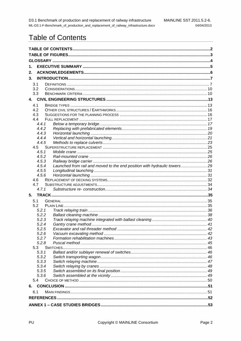
Table of Contents
TABLE OF CONTENTS ........................................................................................................................... 2
TABLE OF FIGURES ............................................................................................................................... 3
GLOSSARY ............................................................................................................................................. 4
1. EXECUTIVE SUMMARY .................................................................................................................. 5
2. ACKNOWLEDGEMENTS ................................................................................................................. 6
3. INTRODUCTION ............................................................................................................................... 7
3.1 DEFINITIONS ............................................................................................................................... 7 3.2 CONSIDERATIONS ...................................................................................................................... 10 3.3 BENCHMARK CRITERIA ............................................................................................................... 10
4. CIVIL ENGINEERING STRUCTURES ...........................................................................................13
4.1 BRIDGE TYPES .......................................................................................................................... 13 4.2 OTHER CIVIL STRUCTURES / EARTHWORKS ................................................................................. 16 4.3 SUGGESTIONS FOR THE PLANNING PROCESS .............................................................................. 16 4.4 FULL REPLACEMENT .................................................................................................................. 17
4.4.1 Below a temporary bridge ................................................................................................ 17 4.4.2 Replacing with prefabricated elements ............................................................................ 19 4.4.3 Horizontal launching ........................................................................................................ 20 4.4.4 Vertical and horizontal launching ..................................................................................... 21 4.4.5 Methods to replace culverts ............................................................................................. 23
4.5 SUPERSTRUCTURE REPLACEMENT ............................................................................................. 25 4.5.1 Mobile crane .................................................................................................................... 25 4.5.2 Rail-mounted crane ......................................................................................................... 26 4.5.3 Railway bridge carrier ...................................................................................................... 26 4.5.4 Launched from rail and moved to the end position with hydraulic towers ....................... 29 4.5.5 Longitudinal launching ..................................................................................................... 31 4.5.6 Horizontal launching ........................................................................................................ 31
4.6 REPLACEMENT OF DECKING SYSTEMS ......................................................................................... 32 4.7 SUBSTRUCTURE ADJUSTMENTS .................................................................................................. 34
4.7.1 Substructure re- construction ........................................................................................... 34
5. TRACK ............................................................................................................................................35
5.1 GENERAL .................................................................................................................................. 35 5.2 PLAIN LINE ................................................................................................................................ 35
5.2.1 Track relaying train .......................................................................................................... 36 5.2.2 Ballast cleaning machine ................................................................................................. 38 5.2.3 Track relaying machine integrated with ballast cleaning ................................................. 40 5.2.4 Gantry crane method ....................................................................................................... 41 5.2.5 Excavator and rail threader method ................................................................................ 42 5.2.6 Vacuum excavating method ............................................................................................ 42 5.2.7 Formation rehabilitation machines ................................................................................... 43 5.2.8 Puscal method ................................................................................................................. 45
5.3 SWITCHES ................................................................................................................................. 46 5.3.1 Ballast and/or sublayer renewal of switches .................................................................... 46 5.3.2 Switch transporting wagon ............................................................................................... 46 5.3.3 Switch relaying machine .................................................................................................. 47 5.3.4 Switch relaying by cranes ................................................................................................ 48 5.3.5 Switch assembled on its final position ............................................................................. 49 5.3.6 Switch assembled at the vicinity ...................................................................................... 49
5.4 CHOICE OF METHOD .................................................................................................................. 50
6. CONCLUSION ................................................................................................................................51
6.1 MAIN FINDINGS .......................................................................................................................... 51
REFERENCES .......................................................................................................................................52
ANNEX 1 – CASE STUDIES BRIDGES ................................................................................................53

D3.1 Benchmark of production and replacement of railway infrastructure MAINLINE SST.2011.5.2-6.
ML-D3.1-F-Benchmark_of_production_and_replacement_of_railway_infrastructure.docx 04/04/2013
PU Copyright © MAINLINE Consortium Page 3
Table of figures
Figure 1 Bridge components (Network Rail, NR/L3/CIV/006/2C, Handbook for the Examination of Structures: Part 2C Condition Marking of Bridges) ..................................................................................8
Figure 2 Track components ......................................................................................................................9
Figure 3 Table for the rating of methods ............................................................................................... 11
Figure 4 Concrete superstructure on stone supports (top left), RC frame bridge (top right) and masonry arch bridge (bottom) ............................................................................................................... 13
Figure 5 Truss bridge ............................................................................................................................ 14
Figure 6 Steelwork U-frame Bridge (Calder Viaduct, UK) ..................................................................... 14
Figure 7 Typical three span concrete bridge (Sweden) ........................................................................ 15
Figure 8 Concrete arch bridge (Åby River bridge Sweden) .................................................................. 16
Figure 9 Temporary bridge used in DB ................................................................................................. 18
Figure 10 Active rails to be installed ...................................................................................................... 18
Figure 11 Small underpath built with prefabricated elements (Denmark) ............................................. 20
Figure 12 Construction site with launching beams to slide a bridge in one direction (Denmark) ......... 21
Figure 13 Construction site with horizontal and vertical launching (Denmark) ..................................... 22
Figure 14 Construction of a steel plate culvert (Sweden) ..................................................................... 24
Figure 15 Railway bridge carrier with the new bridge loaded is approaching the old bridge ................ 27
Figure 16 The new bridge has been lowered into place. ...................................................................... 27
Figure 17 A complete bridge swap with railway bridge carrier .............................................................. 28
Figure 18 Replacing a steel superstructure launched from rail with hydraulic towers .......................... 30
Figure 19 Steel truss arch with replaced top structure (Forsmo bridge over Ångerman River Sweden)32
Figure 20 Railmounted redecking with frp plates .................................................................................. 33
Figure 21 FRP decking types taken from SKM [9]; (cellular to left, moulded to middle, pultruded heavy duty grating to right) ............................................................................................................................... 33
Figure 22 Grouting for acceptable layup of new superstructure on existing supports .......................... 34
Figure 23 Overview of track renewal techniques .................................................................................. 35
Figure 24 Schematic drawing of a track relaying train without crawlers (COMSA) ............................... 36
Figure 25 Track relaying train without crawlers on operation (COMSA) ............................................... 37
Figure 26 SUZ (cf. ETR 03/2004) .......................................................................................................... 38
Figure 27 Ballast cleaning machine on operation (COMSA) ................................................................. 39
Figure 28 RU 800 S (cf. Plasser & Theurer) ......................................................................................... 41
Figure 29 Track renewal process using gantry cranes (COMSA) ......................................................... 42
Figure 30 Track renewal process using excavators and rail threaders (COMSA) ................................ 42
Figure 31 Vaccum excavator machine Jumbo (cf. Plasser & Theurer) ................................................. 43
Figure 32 AHM 800 R (cf. ETR 09/2000) .............................................................................................. 44
Figure 33 PM 1000 URM (cf. Eurailpool) .............................................................................................. 44
Figure 34 PUSCAL IV (cf. rail.lu) ........................................................................................................... 45
Figure 35 Overview of renewal techniques for switches ...................................................................... 46
Figure 36 Switch relaying machine with orientable crawlers (cf. DESEC) ............................................ 47
Figure 37 Switch relaying machine WM 500 U and switch transportation wagon WTW ...................... 48
Figure 38 Switch relaying by crane (cf. Marx, Moßmann; 2011) ........................................................... 48
Figure 39 Assembly of a switch on side 1 (cf. Swietelsky) .................................................................... 49
Figure 40 Assembly of a switch on side 2 (cf. Swietelsky) .................................................................... 50
D3.1 Benchmark of production and replacement of railway infrastructure MAINLINE SST.2011.5.2-6.
ML-D3.1-F-Benchmark_of_production_and_replacement_of_railway_infrastructure.docx 04/04/2013
PU Copyright © MAINLINE Consortium Page 4
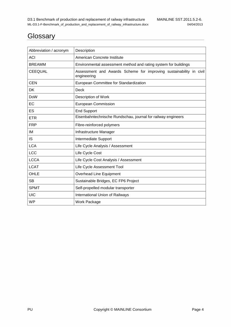
Glossary
Abbreviation / acronym Description
ACI American Concrete Institute
BREAMM Environmental assessment method and rating system for buildings
CEEQUAL Assessment and Awards Scheme for improving sustainability in civil engineering
CEN European Committee for Standardization
DK Deck
DoW Description of Work
EC European Commission
ES End Support
ETR Eisenbahntechnische Rundschau, journal for railway engineers
FRP Fibre-reinforced polymers
IM Infrastructure Manager
IS Intermediate Support
LCA Life Cycle Analysis / Assessment
LCC Life Cycle Cost
LCCA Life Cycle Cost Analysis / Assessment
LCAT Life Cycle Assessment Tool
OHLE Overhead Line Equipment
SB Sustainable Bridges, EC FP6 Project
SPMT Self-propelled modular transporter
UIC International Union of Railways
WP Work Package
D3.1 Benchmark of production and replacement of railway infrastructure MAINLINE SST.2011.5.2-6.
ML-D3.1-F-Benchmark_of_production_and_replacement_of_railway_infrastructure.docx 04/04/2013
PU Copyright © MAINLINE Consortium Page 5
1. Executive summary
This report gives an overview of existing techniques to replace railway infrastructure. It differentiates between bridges and track and compiles methods used across Europe.
In particular this document presents European practice for replacement methods and helps to give advice to infrastructure managers to find the suitable method for their specific construction problem. Therefore this collection aims to present methods for the most important parts of the fixed long life railway infrastructure; especially bridges, track and turnouts. The reader will find method descriptions for several methods to completely or partially replace the life expired infrastructure.
The option selection or decision making process and the life cycle cost (LCC) analysis that might have influenced the decision to replace the infrastructure does not form part of this report. This very important activity is handled in Work Package 5 but does not affect replacement methodologies.
This report is addressed to the asset maintenance engineers within the railways infrastructure owners or working for consultants and others involved in the planning and design of infrastructure renewal.
Every infrastructure manager will have his/her own overriding network specific issues for every single project which will require consideration. Not only are financial issues of great importance, consideration will be given to different maintenance strategies, length of available traffic interruptions (and thus time available to replace infrastructure), the possibility of rerouting and the train density in the network which differ from country to country.
The most appropriate method for every specific situation strongly depends on available budget, track possession and site conditions. To help in the decision making for the best method this report will not only give short method descriptions but also extra information on construction cost and track possession time needed. The report includes tables to quickly check these important parameters. Every method that is presented also has a rating for Risk/Uncertainties and for track works information about the quality reached and the allowed speed is provided.
To better describe the methods to the reader, case studies are presented in the Annexes.
From the MAINLINE “D1.1: Benchmark of new technologies to extend the life of elderly rail infrastructure” [1] the results from a bridge questionnaire that was circulated between twelve Infrastructure Managers (IM) was extrapolated. It turned out that in the next 10 years it may be expected to strengthen some 1 500 bridges, to replace some 4 500 bridges and to replace the deck of some 3 000 bridges. One can see the need for suitable and reliable methods to completely or partially replace bridges. Understanding that track works are carried out even more frequently than bridge works, this compendium will be of good use for all infrastructure engineers and managers involved with maintenance and renewal planning.
D3.1 Benchmark of production and replacement of railway infrastructure MAINLINE SST.2011.5.2-6.
ML-D3.1-F-Benchmark_of_production_and_replacement_of_railway_infrastructure.docx 04/04/2013
PU Copyright © MAINLINE Consortium Page 6
2. Acknowledgements
Contributions to this report have been given by the following partners in Mainline:
- UIC, FR (Björn Paulsson)
- COWI, DK (Poul Linneberg)
- LTU, SE (Lennart Elfgren)
- DB Netz AG, DE (Britta Schewe)
- Graz University of Technology, AT (Stefan Marschnig)
- COMSA, ES (Valenti Fontsere Pujol, Carlos Saborido)
- Trafikverket, SE (Björn Paulsson, Anders Carolin)
- SKM, UK (Lee Canning, Simon Walters)
D3.1 Benchmark of production and replacement of railway infrastructure MAINLINE SST.2011.5.2-6.
ML-D3.1-F-Benchmark_of_production_and_replacement_of_railway_infrastructure.docx 04/04/2013
PU Copyright © MAINLINE Consortium Page 7
3. Introduction
Within the railway network the time and space for maintenance activities is limited. Passenger and freight traffic are of high importance for the European community. Down times of the railway network not only cause problems in the dense commuter areas, they also hinder the flow of cargo from one part of Europe to another. The system of trains and their interaction is precisely planned in timetables that have a lot of connections and interfaces. Any disturbance is crucial to follow up traffic or interconnections, and comes at a cost to the infrastructure managers and/or train operators. All infrastructure managers therefore try to limit necessary interruptions of regular traffic to a minimum. Nevertheless maintenance has to be done to continuously ensure safe and secure railway traffic. The rail networks currently managed in Europe are of significant age, with infrastructure life expectations set to perpetuate the longevity of the rail network, and expected to remain in service with low levels of maintenance across their lives due to the issues of disruption and remoteness.
A very special part of keeping the railway network in service is finally the replacement of obsolete infrastructure. When bridges reach the end of their service life or bridge deck condition is heavily deteriorated, replacement is inevitable. The resultant reconstruction inevitably causes great disturbance to the normal operation of the railway network; one tries to avoid it as long as possible and uses methodologies to prolong service life. These elements are considered in parts in all other WPs of MAINLINE. At some point there is no economically efficient strengthening method and then replacement methods and logistics are necessary.
This report will present accepted practice methods used across Europe to give alternatives to the most common replacement problems concerning bridges, track and switches and crossings.
3.1 Definitions
This report focuses on construction methods beyond maintenance activities. Ideas to strengthen old infrastructure are given in ML-D1.1 (2012): Benchmark of new technologies to extend the life of elderly rail infrastructure [1].
All repair and strengthening is done as long this is an economical alternative for infrastructure network. But in some cases replacement of the old infrastructure is the only solution to maintain railway network operations.
A typical example of this is the replacement of old steel beams with low bearing capacity and the associated direct sleeper track with a new concrete or composite steel RC structure with ballasted track. The resultant bridge will attract a full new service life expectancy, possibly with room for future network enhancement and upgraded bearing capacity.
D3.1 Benchmark of production and replacement of railway infrastructure MAINLINE SST.2011.5.2-6.
ML-D3.1-F-Benchmark_of_production_and_replacement_of_railway_infrastructure.docx 04/04/2013
PU Copyright © MAINLINE Consortium Page 8
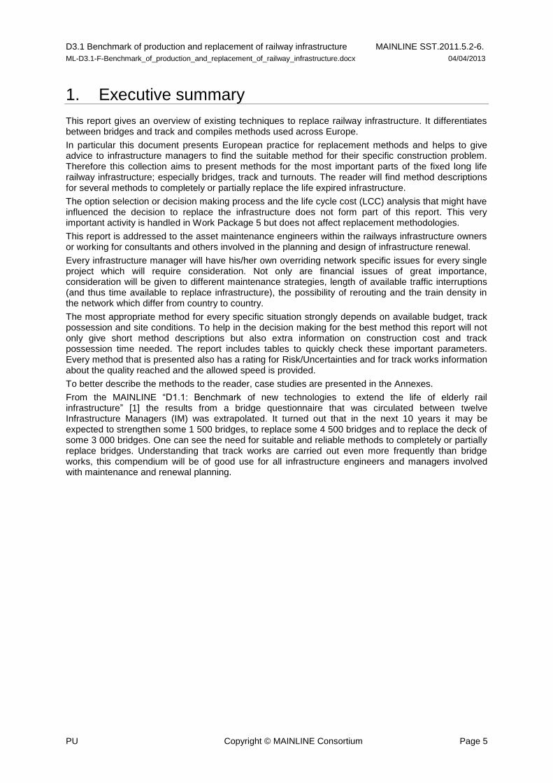
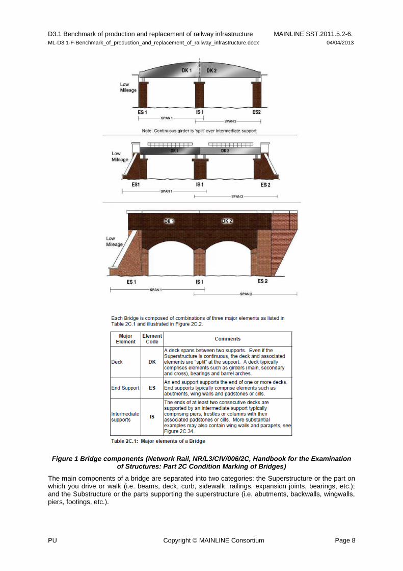
Figure 1 Bridge components (Network Rail, NR/L3/CIV/006/2C, Handbook for the Examination of Structures: Part 2C Condition Marking of Bridges)
The main components of a bridge are separated into two categories: the Superstructure or the part on which you drive or walk (i.e. beams, deck, curb, sidewalk, railings, expansion joints, bearings, etc.); and the Substructure or the parts supporting the superstructure (i.e. abutments, backwalls, wingwalls, piers, footings, etc.).
D3.1 Benchmark of production and replacement of railway infrastructure MAINLINE SST.2011.5.2-6.
ML-D3.1-F-Benchmark_of_production_and_replacement_of_railway_infrastructure.docx 04/04/2013
PU Copyright © MAINLINE Consortium Page 9
According to the components of the bridge that are replaced, one can distinguish different types of replacement. Different types for replacement are described shortly.
Full replacement
The whole existing structure is replaced, i.e. both sub- and superstructure are replaced. A new superstructure can often be constructed adjacent to or underneath the old bridge and then the superstructure is transferred into place. Compared to building a new bridge in an existing track, the majority of earthworks are already done.
Small bridges are often the ones that will have a full replacement.
Superstructure replacement
The most common type of replacement. The substructure is kept after modification and possible strengthening. Minimum amount of earthwork is required.
Suitable for all types of bridges from small span to medium sized span; concrete and steel
Partial replacement
Parts of superstructures are included in the new superstructure and/or superstructure is replaced completely but phased with the existing structure removal. A common example is retention of existing superstructure girders but replacement of deck elements.
Overbuild and supersede
Arch bridges and small concrete bridges are overbuilt with slabs. The new structure is designed to carry the loads and that is the reason why this should be seen as a replacement method. However, the old structure is kept in place and is in many cases needed to serve as a strut member to hold the existing supports apart.
Combined methods
In reality, methods often need to be combined to make a successful bridge replacement. Railway bridge carriers can be used to place the new bridge while the old bridge is laterally launched onto temporary support for later demolishing. This may be associated with a temporary or permanent realignment of the permanent way.
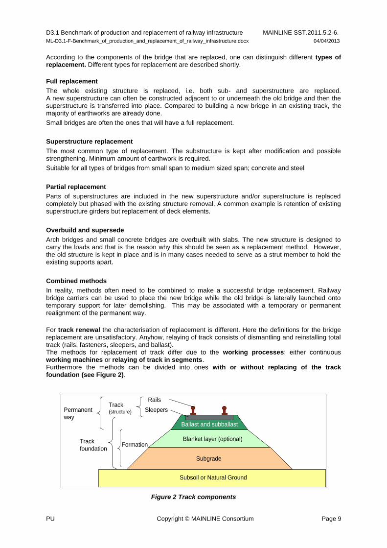
For track renewal the characterisation of replacement is different. Here the definitions for the bridge replacement are unsatisfactory. Anyhow, relaying of track consists of dismantling and reinstalling total track (rails, fasteners, sleepers, and ballast). The methods for replacement of track differ due to the working processes: either continuous working machines or relaying of track in segments. Furthermore the methods can be divided into ones with or without replacing of the track foundation (see Figure 2).
Figure 2 Track components
Subsoil or Natural Ground
Subgrade
Blanket layer (optional)
Ballast and subballast
Rails
SleepersTrack(structure)
FormationTrack
foundation
Permanent
way
D3.1 Benchmark of production and replacement of railway infrastructure MAINLINE SST.2011.5.2-6.
ML-D3.1-F-Benchmark_of_production_and_replacement_of_railway_infrastructure.docx 04/04/2013
PU Copyright © MAINLINE Consortium Page 10
3.2 Considerations
In reconstruction of railway infrastructure nearly all parameters are determined in advance. The network and the track geometry already exist and only in a very few cases is larger track relaying possible. Normally the cross section of the line does not give any room for widening the track distance. Additionally, the free opening and clearance underneath a bridge should as far as possible not be reduced. It is often a desire for the newly built or replacement bridges to have automatically a higher construction height than old ones due to changed design rules – this often then requires vertical realignment of the track to a significant length at the bridge approaches as well as on the bridge.
When all this is combined with an inner city line and constricted room to construct the bridge, the logistics become very complicated.
Some countries have further specific and technical requirements from the network owner that need to be considered when planning new build. Some examples:
- Post-tensioning is not allowed if it can be avoided;
- Traditional waterproofing using bituminous membranes with protective concrete is required
- Limits to the allowable time for track closure
- Load carrying capacity is not allowed to decrease
- Train traffic interruption must be minimized
- Change from direct sleepers to ballasted track
- It is preferable to keep overhead contact line in place
- Often increased load carrying capacity wanted and fully Eurocode compliant bridge structure
(old infrastructure is rarely fully Eurocode compliant, particularly in the case of actions due to
derailment).
- Retention or sympathetic alteration of material or visual appearance for historically important
bridges.
All of the above have a significant influence on the method chosen when replacing the bridges. Therefore, in order to determine the optimal bridge replacement strategy, it is required to know which parameters each individual bridge owner focuses on when determining bridge replacements. The presented replacement methods cover logistics for replacing railway carrying structures over water as well as structures over roads. The access to the bridge site will vary depending on location, possible traffic situation and space in the surroundings.
In many countries time is the governing parameter when replacing bridges - i.e. the method requiring the shortest possible track closure is preferred no matter the related cost (within reasonable limits).
3.3 Benchmark criteria
As mentioned above many parameters have a crucial impact on the selection of the right method for the replacement activity. For the detailed planning of infrastructure replacement works different topics will be looked at. These criteria are very different from one country to another and also from infrastructure manager to infrastructure manager.
To make decisions on methods easier some main criteria have been collected and assembled. All methods will have details to these selected categories.
To enable qualitative comparison of technologies a series of benchmarking categories are required together with a consistent scoring system. To maximise objectivity, scores should be based upon critical review of a database of projects (from as many countries as possible) that provide detailed evidence of project duration, cost, risks and other aspects. These criteria were collected in “MAINLINE Benchmarking Procedures and Framework” [2] produced by SKM.
To ensure that one can compare construction methods and/or logistics the WP decided to select parameters from those proposed in the mentioned report. Not all are suitable or promising criteria for replacement methods. Thus WP3 selected 4 criteria to evaluate the techniques. The description is taken from the “MAINLINE Benchmarking Procedures and Framework” report:
D3.1 Benchmark of production and replacement of railway infrastructure MAINLINE SST.2011.5.2-6.
ML-D3.1-F-Benchmark_of_production_and_replacement_of_railway_infrastructure.docx 04/04/2013
PU Copyright © MAINLINE Consortium Page 11
Design Life/Durability
Design Life/Durability covers the proven (or expected if no proof is available) durability of a technology in the construction environment. Where there is little or no proof or supporting evidence of durability in the construction environment (i.e. technologies not yet in the application stage) then a low score should be given, and a comment made in the ‘Risk’ category. The conclusions and questionnaire responses from Deliverable 2.1 should also be used to provide information on durability. In addition, the Design Life/Durability (i.e. degradation mechanisms) for new technologies could be considered in Deliverable 2.2.
Speed / track possession
Speed covers how quickly the technology can be used, and therefore how it may impact on the function of the operational railway. Technologies that require lengthy durations for their installation/use and cause major disruption to the railway should receive a low score.
Sustainability
Material Efficiency is related to sustainability, however, current methods to measure sustainability (e.g. BREAMM, CEEQUAL, Inventory of Carbon and Energy) are varied and partly subjective, with a lack of unbiased information sources. Therefore, it is considered that assessing material efficiency is more suitable, as generally heavy/bulky technologies are either more difficult to transport (low sustainability) or have high embodied carbon/energy (low sustainability). Technologies that require a large volume or weight of material should receive a low score. It may also be possible to consider using CO2 values as a ranking method for the various technologies using the conclusions from the Deliverable 5.2 We need to review if this is the case.
Cost
Cost is based on the cost impact of a particular technology. It is important that this only covers the cost to install/use/maintain the technology (not other costs such as railway possession costs, access costs etc. which vary significantly depending on the particular project and are rated in the other benchmarking categories). If a technology has a particular advantage (e.g. remote sensing technologies that do not require in-situ installation) or disadvantage (e.g. intrusive replacement of a bridge component that cannot avoid railway possessions) that could have a major impact on cost, this can be stated as a comment. A reference to case studies giving detailed cost breakdowns can also be given.
Risk/Uncertainties Risk is based on the risk to the infrastructure and operational railway. A technology that imports risk or once installed leaves a significant residual risk should receive a low score. An example of this would be temporary propping of a bridge which leaves a residual long-term risk. Major risks associated with a particular technology can be stated as a comment.
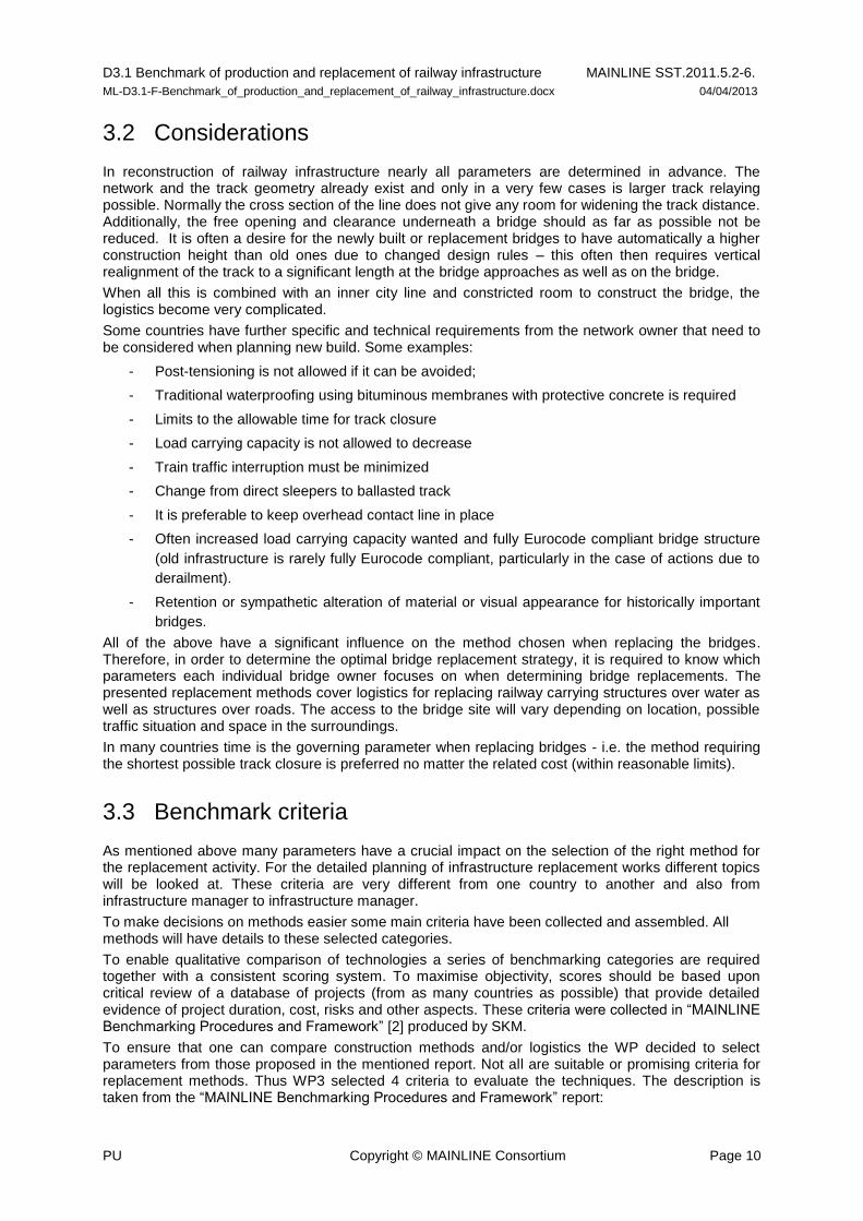
This report aims to evaluate certain methods and to give a chance to make a selection between several promising methods. Therefore every method will have a score for these mentioned categories. An easy overview is a table with a scoring system. One can find to summarize the technology. In this table there will also be free text to precise the scoring when necessary.
Track possession 6-16 hours 6-8 days 1 month
required at the start and the end of the project to establish and remove the temporary track supports; reduced line speed 20-40 km/h
Replacement
Design life/durability
full Replacement partial Replacement
100 years 50 years 10 years
Risk negligible risk (well-known technology, standard)
minor risk major risk
Figure 3 Table for the rating of methods

D3.1 Benchmark of production and replacement of railway infrastructure MAINLINE SST.2011.5.2-6.
ML-D3.1-F-Benchmark_of_production_and_replacement_of_railway_infrastructure.docx 04/04/2013
PU Copyright © MAINLINE Consortium Page 12
These criteria and the described special demands for construction works in the railway environment will be important for the decision making for the right method.

D3.1 Benchmark of production and replacement of railway infrastructure MAINLINE SST.2011.5.2-6.
ML-D3.1-F-Benchmark_of_production_and_replacement_of_railway_infrastructure.docx 04/04/2013
PU Copyright © MAINLINE Consortium Page 13
4. Civil engineering structures
4.1 Bridge types
This report deals with railway bridges: bridges that carry railway loading. Road bridges are not within the scope although many methods that are presented here can be used for road bridges, too.
For the planning process of the replacement, it is also important to understand the current structure surroundings and constraints. This includes whether there is traffic underneath, a building site next to the old bridge or generally the accessibility of the site to construction traffic.
All these parameters will influence the choice of construction type of the new infrastructure. Possibly these boundary conditions also determine the decision for full replacement or partial replacement. Depending on importance of the line, train density and possible (and/or allowable) traffic interruptions, this decision is taken.
First of all, one can divide bridges based on their span length. Knowing first the span of the new bridge and materials, the bridge design can be determined for the most efficient use of materials. This will influence the construction logistics considerably.
Bridge types can be divided into three main groups: small, medium and large bridges. The here used definition and span length is shown below.
Small bridges
Small bridges have a span 2m ≤ x < 10m and represent about 80% of the railway bridge stock in Europe (see Sustainable Bridges (SB) report D1.1 [3]).
Small bridges do not have bearings. Typical bridge types are shown in Figure 4.
Figure 4 Concrete superstructure on stone supports (top left), RC frame bridge (top right) and masonry arch bridge (bottom)
D3.1 Benchmark of production and replacement of railway infrastructure MAINLINE SST.2011.5.2-6.
ML-D3.1-F-Benchmark_of_production_and_replacement_of_railway_infrastructure.docx 04/04/2013
PU Copyright © MAINLINE Consortium Page 14
In this category a large number of arch bridges also exist. Their construction material varies from masonry and stone with regional very different material quality. In some countries steel pipe bridges are commonly found for this small span length.
Small bridges can often be easily exchanged. The way to replace these bridges mainly depends on the accessibility of the site. Due to the short span the weight of the complete bridge is usually not very high and can be lifted into position by crane from a local construction area.
If cranes are difficult to place next to the bridge, the superstructure can easily be replaced with railway bridge carrier.
Medium bridges
Medium bridges have spans from 10-30m. These bridges may or may not have bearings. Single span bridges in this range will often have bearings.
Single span bridges type can be exchanged, most likely by lateral moving from and to temporary supports.
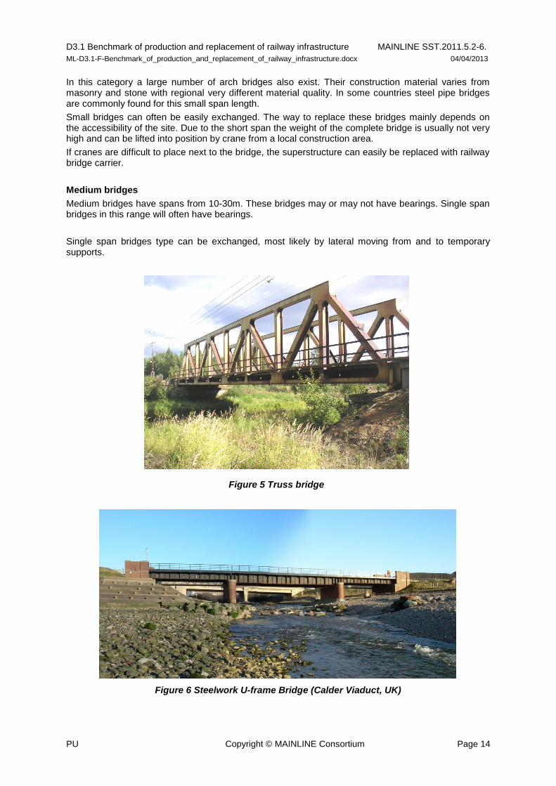
Figure 6 Steelwork U-frame Bridge (Calder Viaduct, UK)
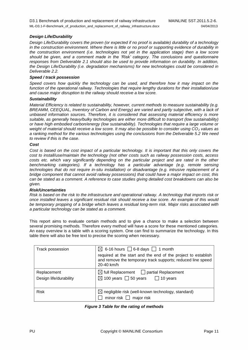
Figure 5 Truss bridge

D3.1 Benchmark of production and replacement of railway infrastructure MAINLINE SST.2011.5.2-6.
ML-D3.1-F-Benchmark_of_production_and_replacement_of_railway_infrastructure.docx 04/04/2013
PU Copyright © MAINLINE Consortium Page 15
A very characteristic bridge for medium sized bridge is the truss bridge. Steelwork U-frame bridges are also common within this span range. These bridge types are closely linked to the development of the railway network across Europe. Therefore many of these bridges have been in service for more than 100 years already. Often the main problem for replacement of truss bridges is the surrounding. Due to their weight and construction height they are often found crossing small rivers or channels. Here specific logistics are needed and exact planning is essential.
A typical three span bridge as shown in Figure 7 does not have bearings. Those multispan integral bridges are normally not exchanged.
Figure 7 Typical three span concrete bridge (Sweden)
Instead a new bridge is built closely and the track is moved onto the new bridge. If it comes to replacement, the biggest challenge is to remove the old structure. Inserting a new bridge is rather fast and straight forward.
Problems connected to removing an old structure is less for a bridge with bearings, hence it follows that a medium sized bridge with bearings can still easily be replaced.
Medium sized bridges can be replaced in full or by replacement of superstructure.
Large bridge
Large bridges in the definition used for this report are bridges that have a span > 30m. They are typically difficult and expensive to replace and require long railway possessions (perhaps at least one week). Wherever possible a new bridge is built closely and the track is moved onto the new bridge. However, moving the track is expensive and a lot of money could be spent on a new structure for a lower cost.
Most likely, only parts will be exchanged. One can discuss if partial replacement should be seen as strengthening of the existing structure or replacement. This document will not make such difference but include partial replacement as an effective method.

D3.1 Benchmark of production and replacement of railway infrastructure MAINLINE SST.2011.5.2-6.
ML-D3.1-F-Benchmark_of_production_and_replacement_of_railway_infrastructure.docx 04/04/2013
PU Copyright © MAINLINE Consortium Page 16
Figure 8 Concrete arch bridge (Åby River bridge Sweden)
Because of the size there can be possibilities to construct a new bridge around the old one. For the presented example a new arch may be built below the existing. It may also be possible to erect new structures aside the existing one and then place a new superstructure between. It is also possible to place a truss structure on top of the old bridge and slightly raise the track.
When such project is finalized the structure will have been fully replaced. The phased construction procedure where the old structure is part of the new structure, can be more economical compared to partial replacement.
4.2 Other civil structures / Earthworks
Besides bridges there exist other civil structures to support railway tracks.
First of all there are all types of geotechnical constructions such as embankments, cuttings and abutments. In general strengthening is more often used in this area. Completely new build situations are rare. As this report presents methods for replacement, this area is not within the scope.
Culverts and ducts are small with a span or diameter ≤ 2 m and are therefore not defined as bridges. They are more or less comparable to a bridge regarding construction work, planning and calculation. However, these structures are not the main topic of this report even though many of the presented methods are suitable.
Culverts are also sometimes pushed under the rail when the track is placed on an embankment … even for tracks at ground level this method may be used using excavations on both sides of the tracks. In the sense of bridge replacement considered in this report, the new ‘bridge’ is built next to the old one and the method is more compared to erecting a new ‘bridge’ and demolishing the old one separately.
When bridges are pushed under the embankment, the damage on the outer surface must be considered. Steel pipes must for instance have sufficient thickness to allow for corrosion since the outer protection will be damaged.
4.3 Suggestions for the planning process
The track possession required for the replacement of a bridge structure has to be well planned and prepared, bearing in mind the train traffic and aiming for the shortest closure possible, the road closure and actual logistics for the construction method.
Some recommendations for the time planning are:

D3.1 Benchmark of production and replacement of railway infrastructure MAINLINE SST.2011.5.2-6.
ML-D3.1-F-Benchmark_of_production_and_replacement_of_railway_infrastructure.docx 04/04/2013
PU Copyright © MAINLINE Consortium Page 17
- The old structure should be prepared for removal before the traffic stop (diversion of services etc.)
- All work to adjust existing parts that should be reused should be done prior to the possession. - Limited speed after possible removal of track - Work that affects track can only be undertaken at certain temperatures
To facilitate such work, the sleeper distance might need to be temporary increased.
The maximum distances between two adjacent sleepers that can be allowed depends on particular national standards and will be governed by the rail type, traffic loads, traffic intensity and duration of works. As an indication, a center to center distance can for some cases be 0.75 m, giving a free opening of approximately 0.5 m. The demolition work can then be carried out stepwise; some works are done as preparation before the change and remaining work is done afterwards. This facilitates, space and positioning of both existing and new bearings at the same time.
When the bridge change takes place in areas where all the work is undertaken on the track, the placement of the new ballasted track needs planning. The new track must allow the wagons with ballast to pass the bridge before it is in its final position. With temporary supports of the new sleepers at the ends the ballast wagon may pass the bridge and unload ballast. The temporary supports are then removed continuously and more ballast is placed. Larger (more than 0.3 m) lifting of existing track is rather easy, the new sleepers are placed on the new bridge surface and the track is lifted in the process of adding ballast and adjustment of the track.
The particular situation for each and every bridge reconstruction must be studied in detail at the planning of the new bridge and the selected solution is likely to affect placement of electrical equipment and services for the trains. General information is also given in [4] Pfeifer and Mölter (2008).
4.4 Full replacement
In this chapter, methods are presented to replace both sub- and superstructure. A complete new bridge is built to replace the old structure.
One advantage with replacing an old bridge with a new compared to erect a new bridge in an existing track is that most of the earth moving work is already done. The main problem is to remove the old structure. It can be very useful if the existing bridge was the outcome from an earlier bridge replacement. In such cases the existing bridge is likely to be already prepared for sliding or other moving techniques. For more complicated cases the presented methods below have found to be useful.
4.4.1 Below a temporary bridge
The main problem in railway networks is to close down the traffic for long periods. Therefore many railway infrastructure managers across Europe have pre designed temporary bridges to use for construction work. These bridges can be easily placed underneath the tracks and then construction works are done underneath these temporary supports. They are in use when the headroom underneath the track allows reducing the construction height of the new bridge. Then construction works are done underneath these temporary supports.
Figure 9 shows only one example for the various types that exist across Europe.

D3.1 Benchmark of production and replacement of railway infrastructure MAINLINE SST.2011.5.2-6.
ML-D3.1-F-Benchmark_of_production_and_replacement_of_railway_infrastructure.docx 04/04/2013
PU Copyright © MAINLINE Consortium Page 18
Figure 9 Temporary bridge used in DB
These bridges can be used several times and are easy to install and remove. They are available in different lengths and are designed for spans from 6 m to 24 m. For the temporary bridges used and designed within DB, the allowable train speed is up to 120 km/h in straight tracks and 90 km/h in curves. These attributes propose a wide range of areas of application. Whenever these temporary bridges are in use, a loading history report should be made. Due to their temporary use, these bridges have their very individual loading history and therefore individual service life.
After installment of the temporary bridge with no ballast and very low structural height, the old bridge is demolished and the new bridge is built underneath the temporary bridge, which is later removed. Old bridges do often have over amounts of ballast which make it easy to fit the temporary bridge. The method can be used for spans up to 25 m.
The existing bridge is taken out from the railway environment and all work is made under the temporary bridge. A temporary bridge is placed on sheet pile walls which are installed in existing track. Then the temporary bridge is placed during a 6-16 h track possession.
When this kind of rail support is used, the trains have to pass the bridge with speed limits usually 20-40 km/h.
The advantage is that all work can be done underneath the support. E.g. demolition of the old bridge but also old supports can be retrofitted and prepared for a superstructure replacement.
There are several methods for active tracks available in the European market (see references [4], [5] and [6]). They are different in length, supporting construction and allowable speeds. A system with very high allowable speed is shown in Annex 1 and describes replacement of smaller bridges under “Active tracks”.
Track possession 6-16 hours 6-8 days 1 month
required at the start and the end of the project to establish and remove the temporary track supports; reduced line speed 20-40 km/h
Replacement
Design life/durability
full Replacement partial Replacement
100 years 50 years 10 years
Risk negligible risk (well-known technology, standard)
minor risk major risk
Figure 10 Active rails to be installed
D3.1 Benchmark of production and replacement of railway infrastructure MAINLINE SST.2011.5.2-6.
ML-D3.1-F-Benchmark_of_production_and_replacement_of_railway_infrastructure.docx 04/04/2013
PU Copyright © MAINLINE Consortium Page 19
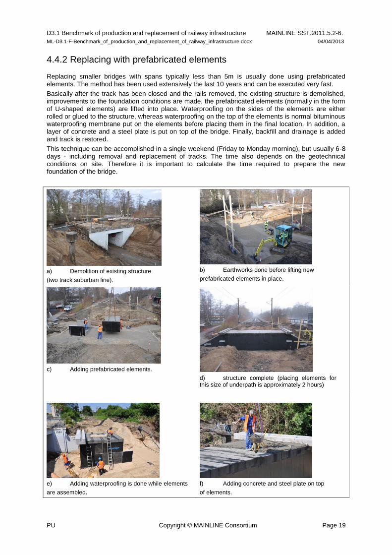
4.4.2 Replacing with prefabricated elements
Replacing smaller bridges with spans typically less than 5m is usually done using prefabricated elements. The method has been used extensively the last 10 years and can be executed very fast.
Basically after the track has been closed and the rails removed, the existing structure is demolished, improvements to the foundation conditions are made, the prefabricated elements (normally in the form of U-shaped elements) are lifted into place. Waterproofing on the sides of the elements are either rolled or glued to the structure, whereas waterproofing on the top of the elements is normal bituminous waterproofing membrane put on the elements before placing them in the final location. In addition, a layer of concrete and a steel plate is put on top of the bridge. Finally, backfill and drainage is added and track is restored.
This technique can be accomplished in a single weekend (Friday to Monday morning), but usually 6-8 days - including removal and replacement of tracks. The time also depends on the geotechnical conditions on site. Therefore it is important to calculate the time required to prepare the new foundation of the bridge.
a) Demolition of existing structure
(two track suburban line).
b) Earthworks done before lifting new
prefabricated elements in place.
c) Adding prefabricated elements.
d) structure complete (placing elements for this size of underpath is approximately 2 hours)
e) Adding waterproofing is done while elements
are assembled.
f) Adding concrete and steel plate on top
of elements.

D3.1 Benchmark of production and replacement of railway infrastructure MAINLINE SST.2011.5.2-6.
ML-D3.1-F-Benchmark_of_production_and_replacement_of_railway_infrastructure.docx 04/04/2013
PU Copyright © MAINLINE Consortium Page 20
g) Tracks restored
Figure 11 Small underpath built with prefabricated elements (Denmark)
The same design life is expected as for in-situ cast concrete structures. The backfill in the transition zone requires additional compacting and track adjustment in the period after replacement - but this is no different to in-situ cast concrete tunnels (if they have the same time to add and compact the backfill).
Track possession weekend (Fri to Mon) 6-8 days 1 month
Usually 6-8 days including removal and replacement of tracks
Replacement
Design life/durability
full Replacement partial Replacement
100 years 50 years 10 years
Risk negligible risk (well-known technology, standard)
minor risk major risk
Strongly depends on the geotechnical conditions
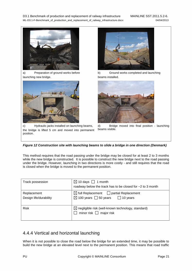
4.4.3 Horizontal launching
When the bridge to be replaced becomes larger, so that prefabricated elements are no longer an option, the normal procedure is to build an in-situ cast bridge next to the bridge to be replaced. The bridge is completed as much as possible - usually including track and waterproofing. When the new bridge is completed, the track is removed, the old bridge demolished and the new bridge launched horizontally into permanent position.
A bridge is cast in-situ next to the bridge to be removed in approximately the same elevation as the final position. When the bridge is completed the existing track is removed, the old bridge demolished and launching beams are placed so that the new bridge can be moved into its permanent position. Before the launching the ground must be prepared for both the new bridge and for the launching beams. However, usually the launching beams can be supported by direct foundation and requires no pile foundation or other permanent structures.
D3.1 Benchmark of production and replacement of railway infrastructure MAINLINE SST.2011.5.2-6.
ML-D3.1-F-Benchmark_of_production_and_replacement_of_railway_infrastructure.docx 04/04/2013
PU Copyright © MAINLINE Consortium Page 21
a) Preparation of ground works before
launching new bridge.
b) Ground works completed and launching
beams installed.
c) Hydraulic jacks installed on launching beams,
the bridge is lifted 5 cm and moved into permanent position.
d) Bridge moved into final position - launching beams visible.
Figure 12 Construction site with launching beams to slide a bridge in one direction (Denmark)
This method requires that the road passing under the bridge may be closed for at least 2 to 3 months while the new bridge is constructed. It is possible to construct the new bridge next to the road passing under the bridge. However, launching in two directions is more costly - and still requires that the road is closed when the bridge is moved to the permanent position.
Track possession 10 days 1 month
roadway below the track has to be closed for ~2 to 3 month
Replacement
Design life/durability
full Replacement partial Replacement
100 years 50 years 10 years
Risk negligible risk (well-known technology, standard)
minor risk major risk
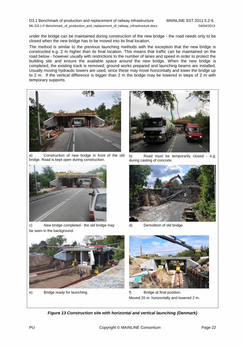
4.4.4 Vertical and horizontal launching
When it is not possible to close the road below the bridge for an extended time, it may be possible to build the new bridge at an elevated level next to the permanent position. This means that road traffic
D3.1 Benchmark of production and replacement of railway infrastructure MAINLINE SST.2011.5.2-6.
ML-D3.1-F-Benchmark_of_production_and_replacement_of_railway_infrastructure.docx 04/04/2013
PU Copyright © MAINLINE Consortium Page 22
under the bridge can be maintained during construction of the new bridge - the road needs only to be closed when the new bridge has to be moved into its final location.
The method is similar to the previous launching methods with the exception that the new bridge is constructed e.g. 2 m higher than its final location. This means that traffic can be maintained on the road below - however usually with restrictions to the number of lanes and speed in order to protect the building site and ensure the available space around the new bridge. When the new bridge is completed, the existing track is removed; ground works prepared and launching beams are installed. Usually moving hydraulic towers are used, since these may move horizontally and lower the bridge up to 2 m. If the vertical difference is bigger than 2 m the bridge may be lowered in steps of 2 m with temporary supports.
a) Construction of new bridge in front of the old bridge. Road is kept open during construction.
b) Road must be temporarily closed - e.g. during casting of concrete.
c) New bridge completed - the old bridge may
be seen in the background.
d) Demolition of old bridge.
e) Bridge ready for launching.
f) Bridge at final position.
Moved 20 m horizontally and lowered 2 m.
Figure 13 Construction site with horizontal and vertical launching (Denmark)
D3.1 Benchmark of production and replacement of railway infrastructure MAINLINE SST.2011.5.2-6.
ML-D3.1-F-Benchmark_of_production_and_replacement_of_railway_infrastructure.docx 04/04/2013
PU Copyright © MAINLINE Consortium Page 23
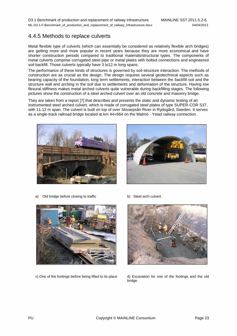
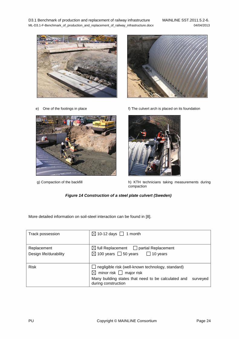
4.4.5 Methods to replace culverts
Metal flexible type of culverts (which can essentially be considered as relatively flexible arch bridges) are getting more and more popular in recent years because they are more economical and have shorter construction periods compared to traditional materials/structural types. The components of metal culverts comprise corrugated steel pipe or metal plates with bolted connections and engineered soil backfill. Those culverts typically have 3 to12 m long spans.
The performance of these kinds of structures is governed by soil-structure interaction. The methods of construction are as crucial as the design. The design requires several geotechnical aspects such as bearing capacity of the foundation, long term settlements, interaction between the backfill soil and the structure wall and arching in the soil due to settlements and deformation of the structure. Having low flexural stiffness makes metal arched culverts quite vulnerable during backfilling stages. The following pictures show the construction of a steel arched culvert over an old concrete and masonry bridge.
They are taken from a report [7] that describes and presents the static and dynamic testing of an instrumented steel arched culvert, which is made of corrugated steel plates of type SUPER-COR S37, with 11.12 m span. The culvert is built on top of over Skivarpsån River in Rydsgård, Sweden. It serves as a single-track railroad bridge located at km 44+664 on the Malmö - Ystad railway connection.
a) Old bridge before closing to traffic b) Steel arch culvert
c) One of the footings before being lifted to its place d) Excavation for one of the footings and the old bridge
D3.1 Benchmark of production and replacement of railway infrastructure MAINLINE SST.2011.5.2-6.
ML-D3.1-F-Benchmark_of_production_and_replacement_of_railway_infrastructure.docx 04/04/2013
PU Copyright © MAINLINE Consortium Page 24
e) One of the footings in place f) The culvert arch is placed on its foundation
g) Compaction of the backfill h) KTH technicians taking measurements during compaction
More detailed information on soil-steel interaction can be found in [8].
Track possession 10-12 days 1 month
Replacement
Design life/durability
full Replacement partial Replacement
100 years 50 years 10 years
Risk negligible risk (well-known technology, standard)
minor risk major risk
Many building states that need to be calculated and surveyed during construction
Steel arch culvert
Figure 14 Construction of a steel plate culvert (Sweden)

D3.1 Benchmark of production and replacement of railway infrastructure MAINLINE SST.2011.5.2-6.
ML-D3.1-F-Benchmark_of_production_and_replacement_of_railway_infrastructure.docx 04/04/2013
PU Copyright © MAINLINE Consortium Page 25
4.5 Superstructure replacement
Not all situations require a full replacement of the bridge. Often a replacement of the superstructure only is sufficient if the substructure is confirmed as adequate. As many railway bridges are single span structure this is an easy and fast way to improve the structural capacity and thus the route availability. The abutments are kept in service and the superstructure is designed to carry the new loading.
The procedure consists of at least two stages, first removal of the old and second placing of the new superstructure. The new structure can be heavier, i.e. steel beams are changed for a composite steel RC structure where the existing substructure is deemed capable of withstanding increased permanent load. With respect to the limited time for the bridge replacement during the possession, it is advisory whenever possible to make sure that the existing bridge is free to move well in advance of the track possession. The existing bridge should be checked to ensure it is not locked in place due to natural bonding of materials over great lengths of time.
For bridges with bearings, some kind of concrete casting is normally made. However, castings take some time for hardening which cannot be allowed during the possession. For this reason the bridge needs some temporary supports. The superstructure, especially steel beams, must be prepared for two or three points for supports for each bearing. Typically three bearing points are needed, one for the temporary support, one for the final support, and one for lifting of the bridge upon removal of the temporary support. However, it is possible to use just two. If the temporary support is made from a box filled with sand it can just be removed when the final support is ready. The sand must be well annealed to make a stiff support yet easy to remove. An advantage with additional lifting points is that future bearing replacements are simplified. Alternatively, bearing replacement is also undertaken as an activity within the possession by using precast concrete bearing units bedded and fixed onto the existing substructure.
Usually smaller superstructures can be replaced in a 12 hour possession. Different methods for superstructure replacement are described below. One needs to decide whatever is best according to local boundaries.
However, combinations of those methods are often needed in more difficult projects.
4.5.1 Mobile crane
Mobile cranes have been successfully used for replacement of smaller bridges. In certain cases it can also be economic to replace bridges by crane for bridges up to 35 meter spans. If the railway embankment is widened or there is already sufficient space it is possible for a large crane to travel along the track. Lifting by crane requires that the old bridge is completely free to move due to elasticity of the crane lifting cables. One disadvantage with cranes is that overhead cables and equipment must be removed during the work. The crane itself is a very important component in the work; however it is difficult to repair the crane if something unexpected occurs (e.g. overloading, adverse weather conditions such as high wind) and high demands on redundancy increase cost significantly.
Track possession weekend (Fri to Mon) 6-8 days 1 month
Usually 6-8 days including removal and replacement of tracks
Replacement
Design life/durability
full Replacement partial Replacement
100 years 50 years 10 years
Risk negligible risk (well-known technology, standard)
minor risk major risk
Strongly depends on the geotechnical conditions
D3.1 Benchmark of production and replacement of railway infrastructure MAINLINE SST.2011.5.2-6.
ML-D3.1-F-Benchmark_of_production_and_replacement_of_railway_infrastructure.docx 04/04/2013
PU Copyright © MAINLINE Consortium Page 26
4.5.2 Rail-mounted crane
There are also cranes made for transportation along the track, although their lifting capacity perpendicular to the track is severely limited compared to mobile cranes. With respect to neighbouring bridges/tracks and the lifting capacity of available cranes in combination with bridge weight, careful planning is necessary. It can be favourable to lift the old bridge out and the new bridge in using a crane. Along the route from construction site to bridges site not only the loading capacity has to be considered but also the available clearance. Otherwise the method is similar to the previous method.
Track possession weekend (Fri to Mon) 6-8 days 1 month
Usually 6-8 days including removal and replacement of tracks
Replacement
Design life/durability
full Replacement partial Replacement
100 years 50 years 10 years
Risk negligible risk (well-known technology, standard)
minor risk major risk
Strongly depends on the geotechnical conditions
4.5.3 Railway bridge carrier
One of the most successful methods that have been used over a long period of time in some countries in Europe is the use of a railway bridge carrier. This carrier is mainly a high built wagon with plenty of space between bogies and hydraulics for lifting and lowering. An ordinary bridge can be replaced with only 12-16 hours possession.
The wagon itself is not motorized for transport. A locomotive is used to tow the wagon. The new superstructure is constructed in a suitable area, preferable not more than 15 km away from the bridge site. Travelling with a bridge loaded is done at a speed of approximately 10 km/h. The procedure is illustrated in Figures 15-17.

D3.1 Benchmark of production and replacement of railway infrastructure MAINLINE SST.2011.5.2-6.
ML-D3.1-F-Benchmark_of_production_and_replacement_of_railway_infrastructure.docx 04/04/2013
PU Copyright © MAINLINE Consortium Page 27
Figure 15 Railway bridge carrier with the new bridge loaded is approaching the old bridge
The locomotive and the first bogie of the wagon are passing the bridge before the replacement begins. Then the old bridge is lifted and turned so it fits between supports, and the new bridge lowered into place (see Figure 16). The wagon and the locomotive can then return. Note that the old bridge still has to be removed, which can be done with traffic on the bridge. The old bridge will in many cases be sent for recycling and may therefore be cut into pieces.
Figure 16 The new bridge has been lowered into place.
D3.1 Benchmark of production and replacement of railway infrastructure MAINLINE SST.2011.5.2-6.
ML-D3.1-F-Benchmark_of_production_and_replacement_of_railway_infrastructure.docx 04/04/2013
PU Copyright © MAINLINE Consortium Page 28
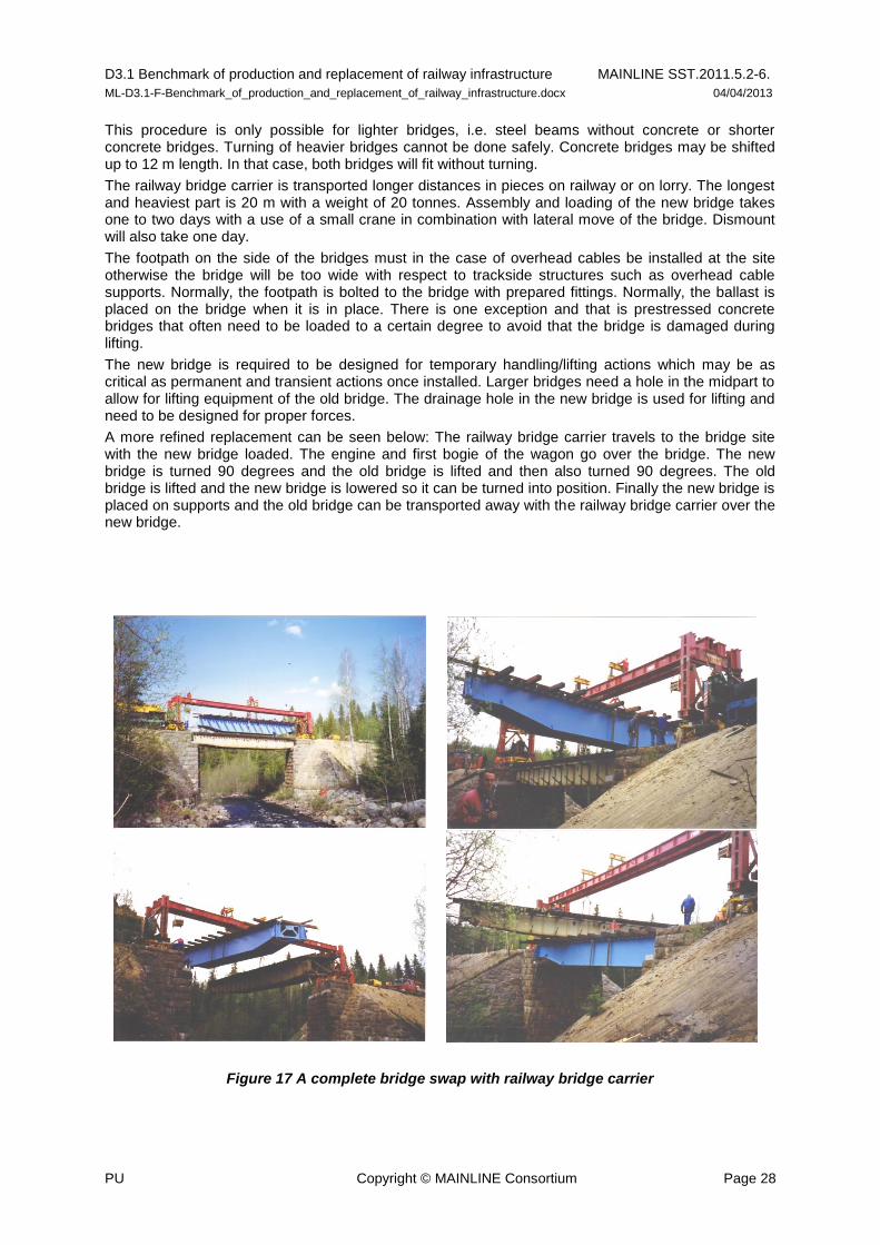
This procedure is only possible for lighter bridges, i.e. steel beams without concrete or shorter concrete bridges. Turning of heavier bridges cannot be done safely. Concrete bridges may be shifted up to 12 m length. In that case, both bridges will fit without turning.
The railway bridge carrier is transported longer distances in pieces on railway or on lorry. The longest and heaviest part is 20 m with a weight of 20 tonnes. Assembly and loading of the new bridge takes one to two days with a use of a small crane in combination with lateral move of the bridge. Dismount will also take one day.
The footpath on the side of the bridges must in the case of overhead cables be installed at the site otherwise the bridge will be too wide with respect to trackside structures such as overhead cable supports. Normally, the footpath is bolted to the bridge with prepared fittings. Normally, the ballast is placed on the bridge when it is in place. There is one exception and that is prestressed concrete bridges that often need to be loaded to a certain degree to avoid that the bridge is damaged during lifting.
The new bridge is required to be designed for temporary handling/lifting actions which may be as critical as permanent and transient actions once installed. Larger bridges need a hole in the midpart to allow for lifting equipment of the old bridge. The drainage hole in the new bridge is used for lifting and need to be designed for proper forces.
A more refined replacement can be seen below: The railway bridge carrier travels to the bridge site with the new bridge loaded. The engine and first bogie of the wagon go over the bridge. The new bridge is turned 90 degrees and the old bridge is lifted and then also turned 90 degrees. The old bridge is lifted and the new bridge is lowered so it can be turned into position. Finally the new bridge is placed on supports and the old bridge can be transported away with the railway bridge carrier over the new bridge.
Figure 17 A complete bridge swap with railway bridge carrier
D3.1 Benchmark of production and replacement of railway infrastructure MAINLINE SST.2011.5.2-6.
ML-D3.1-F-Benchmark_of_production_and_replacement_of_railway_infrastructure.docx 04/04/2013
PU Copyright © MAINLINE Consortium Page 29
Track possession weekend (Fri to Mon) 6-8 days 1 month
Usually 20 hours including removal and replacement of tracks
Replacement
Design life/durability
full Replacement partial Replacement
100 years 50 years 10 years
Risk negligible risk (well-known technology, standard)
minor risk major risk
Strongly depends on the geotechnical conditions
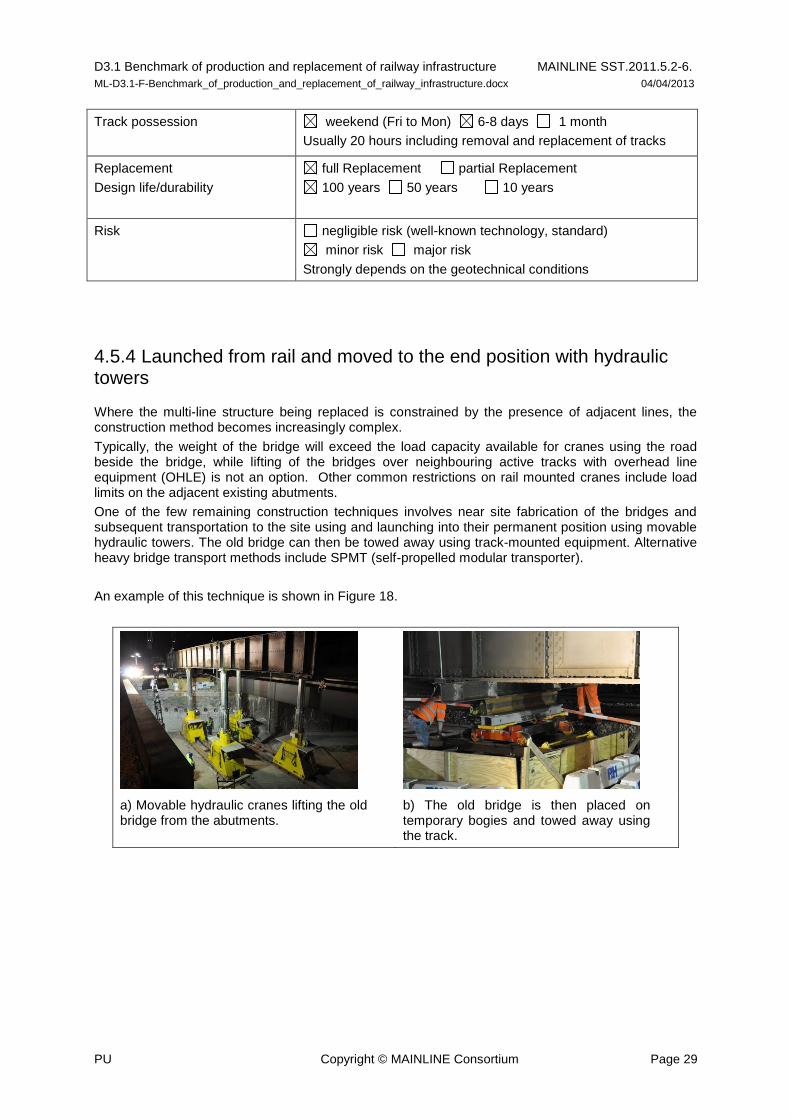
4.5.4 Launched from rail and moved to the end position with hydraulic towers
Where the multi-line structure being replaced is constrained by the presence of adjacent lines, the construction method becomes increasingly complex.
Typically, the weight of the bridge will exceed the load capacity available for cranes using the road beside the bridge, while lifting of the bridges over neighbouring active tracks with overhead line equipment (OHLE) is not an option. Other common restrictions on rail mounted cranes include load limits on the adjacent existing abutments.
One of the few remaining construction techniques involves near site fabrication of the bridges and subsequent transportation to the site using and launching into their permanent position using movable hydraulic towers. The old bridge can then be towed away using track-mounted equipment. Alternative heavy bridge transport methods include SPMT (self-propelled modular transporter).
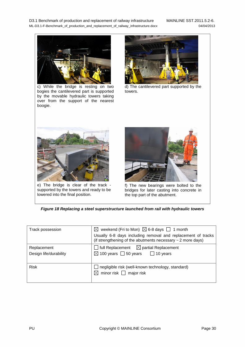
An example of this technique is shown in Figure 18.
a) Movable hydraulic cranes lifting the old bridge from the abutments.
b) The old bridge is then placed on temporary bogies and towed away using the track.
D3.1 Benchmark of production and replacement of railway infrastructure MAINLINE SST.2011.5.2-6.
ML-D3.1-F-Benchmark_of_production_and_replacement_of_railway_infrastructure.docx 04/04/2013
PU Copyright © MAINLINE Consortium Page 30
c) While the bridge is resting on two bogies the cantilevered part is supported by the movable hydraulic towers taking over from the support of the nearest boogie.
d) The cantilevered part supported by the towers.
e) The bridge is clear of the track - supported by the towers and ready to be lowered into the final position.
f) The new bearings were bolted to the bridges for later casting into concrete in the top part of the abutment.
Figure 18 Replacing a steel superstructure launched from rail with hydraulic towers
Track possession weekend (Fri to Mon) 6-8 days 1 month
Usually 6-8 days including removal and replacement of tracks (if strengthening of the abutments necessary ~
2 more days)
Replacement
Design life/durability
full Replacement partial Replacement
100 years 50 years 10 years
Risk negligible risk (well-known technology, standard)
minor risk major risk

D3.1 Benchmark of production and replacement of railway infrastructure MAINLINE SST.2011.5.2-6.
ML-D3.1-F-Benchmark_of_production_and_replacement_of_railway_infrastructure.docx 04/04/2013
PU Copyright © MAINLINE Consortium Page 31
4.5.5 Longitudinal launching
For longer bridges a railway bridge carrier is not possible to be used, the old bridge and the new bridge may be connected to one unit and this unit is then longitudinally moved. Once in the right place the bridges are separated and the new bridge is lowered into position.
Temporary mid-point support is often used for longitudinal launching. In such cases hydraulic towers can be used to lift the bridge and transport it away. One way to avoid new mid supports that has been used in some countries is to lift the old bridge, connect it to the new bridge and use the old bridge as a launching beam when the new bridge is launched in place.
Track possession weekend (Fri to Mon) 6-8 days 1 month
Usually 6-8 days including removal and replacement of tracks
Replacement
Design life/durability
full Replacement partial Replacement
100 years 50 years 10 years
Risk negligible risk (well-known technology, standard)
minor risk major risk
4.5.6 Horizontal launching
This method is presented in the chapter for full replacement but can be used for superstructure replacement as well.
To move a bridge sideways is a rather straight forward procedure and well proven to work. It can be done by placing steel beams on the ground to make a track for temporary roller bearings which are placed under the bridge. A bridge can therefore be built aside the track and then slid into position during a rather short railway possession. In most cases some temporary supports are needed for construction of the new bridge and for a place for the old bridge when it is going to be demolished. By removing footpaths, temporary supports and sliding distance can be minimized.
D3.1 Benchmark of production and replacement of railway infrastructure MAINLINE SST.2011.5.2-6.
ML-D3.1-F-Benchmark_of_production_and_replacement_of_railway_infrastructure.docx 04/04/2013
PU Copyright © MAINLINE Consortium Page 32
4.6 Replacement of decking systems
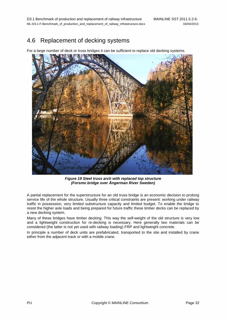
For a large number of deck or truss bridges it can be sufficient to replace old decking systems.
Figure 19 Steel truss arch with replaced top structure (Forsmo bridge over Ångerman River Sweden)
A partial replacement for the superstructure for an old truss bridge is an economic decision to prolong service life of the whole structure. Usually three critical constraints are present: working under railway traffic in possession, very limited substructure capacity and limited budget. To enable the bridge to resist the higher axle loads and being prepared for future traffic these timber decks can be replaced by a new decking system.
Many of these bridges have timber decking. This way the self-weight of the old structure is very low and a lightweight construction for re-decking is necessary. Here generally two materials can be considered (the latter is not yet used with railway loading) FRP and lightweight concrete.
In principle a number of deck units are prefabricated, transported to the site and installed by crane either from the adjacent track or with a mobile crane.

D3.1 Benchmark of production and replacement of railway infrastructure MAINLINE SST.2011.5.2-6.
ML-D3.1-F-Benchmark_of_production_and_replacement_of_railway_infrastructure.docx 04/04/2013
PU Copyright © MAINLINE Consortium Page 33
Figure 20 Railmounted redecking with frp plates
The combination of these constraints, together with a requirement for derailment capacity, limits the available options for the use of FRP composites. Structural options using commercially available FRP composite materials/systems can be summarised as:
Solid CFRP-GFRP hybrid plate, Solid quasi-isotropic GFRP plate, Heavy duty GFRP grating/decking systems with bonded GFRP top plate, Cellular GFRP decking systems, Moulded GFRP decking and Sandwich GFRP decking systems. Examples of these structural options are shown in Figure 21.
Figure 21 FRP decking types taken from SKM [9]; (cellular to left, moulded to middle, pultruded heavy duty grating to right)
A first application of FRP railway decking for full derailment capacity is shown in Annex 1 for the case study “Calder Viaduct Redecking”.
Track possession 6 hours 6-8 days 1 month
for a section from 18-23 m; reduced line speed between the possessions 40 km/h
Replacement
Design life/durability
full Replacement partial Replacement
100 years 50 years 10 years
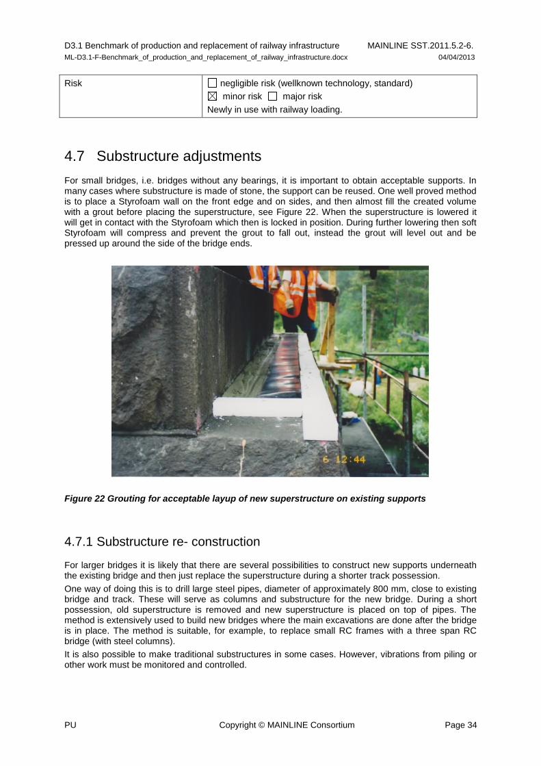
D3.1 Benchmark of production and replacement of railway infrastructure MAINLINE SST.2011.5.2-6.
ML-D3.1-F-Benchmark_of_production_and_replacement_of_railway_infrastructure.docx 04/04/2013
PU Copyright © MAINLINE Consortium Page 34
Risk negligible risk (wellknown technology, standard)
minor risk major risk
Newly in use with railway loading.
4.7 Substructure adjustments
For small bridges, i.e. bridges without any bearings, it is important to obtain acceptable supports. In many cases where substructure is made of stone, the support can be reused. One well proved method is to place a Styrofoam wall on the front edge and on sides, and then almost fill the created volume with a grout before placing the superstructure, see Figure 22. When the superstructure is lowered it will get in contact with the Styrofoam which then is locked in position. During further lowering then soft Styrofoam will compress and prevent the grout to fall out, instead the grout will level out and be pressed up around the side of the bridge ends.
Figure 22 Grouting for acceptable layup of new superstructure on existing supports
4.7.1 Substructure re- construction
For larger bridges it is likely that there are several possibilities to construct new supports underneath the existing bridge and then just replace the superstructure during a shorter track possession.
One way of doing this is to drill large steel pipes, diameter of approximately 800 mm, close to existing bridge and track. These will serve as columns and substructure for the new bridge. During a short possession, old superstructure is removed and new superstructure is placed on top of pipes. The method is extensively used to build new bridges where the main excavations are done after the bridge is in place. The method is suitable, for example, to replace small RC frames with a three span RC bridge (with steel columns).
It is also possible to make traditional substructures in some cases. However, vibrations from piling or other work must be monitored and controlled.

D3.1 Benchmark of production and replacement of railway infrastructure MAINLINE SST.2011.5.2-6.
ML-D3.1-F-Benchmark_of_production_and_replacement_of_railway_infrastructure.docx 04/04/2013
PU Copyright © MAINLINE Consortium Page 35
5. Track
5.1 General
Over the last few decades it has become apparent that there is a steady rise in requirements for efficient methods of replacement of track and turnouts. This is resultant from higher demands on quality of track alignment and a simultaneous decrease of available working time. To optimize the process of track renewal various methods have been developed. The inclusion of the sublayer replacement in the replacement of track or turnouts should be based on an economical decision through LCC or LCA. The different techniques can be subdivided into continuous working machines and the replacement of individual segments.
This section will differentiate between plain line and switches and crossings, given that the latter requires specific renewal methods. General information on track is given in [10] Esveld (2001) and [11] Lichtberger (2005).
Methods depicted are only applicable to ballasted track. For slab track, there are no current known methods for renewal, given that existing ballast-less sections remain still far from the end of their lifespan, and hence, no important renewal in slab track has been carried out up to now. Furthermore, the possible renewal methods might strongly depend on the type of slab track considered, as opposed to ballasted track. If a conversion from ballasted track to slab track is envisaged, there is a need in most cases to increase the bearing capacity of the subsoil to minimize slab track settlements. This kind of renewal is not considered in this document because there are still not common practices and because the main concern in this kind of renewal should be the improvement of the subsoil rather than the construction of the new slab track, which will not differ much from its construction in a new line. In this sense, more information regarding subsoil improvement to enable slab track construction can be found in the INNOTRACK project (see www.innotrack.net), within which new technologies to improve the subgrade were analysed in detail.
5.2 Plain Line
Methods presented in this section refer to the renewal of rail, sleepers and ballast, and optionally, subgrade layer. Some of these methods include the renewal of all components, whilst others allow only the replacement of only some of them. As it can be seen in Figure 23, there are many combinations of replacement methods according to the needs and conditions of the worksite.
Figure 23 Overview of track renewal techniques
Plain line
Without sublayer replacement
Continuous
4.2.3 Track relaying machine
integrated with ballast cleaning
4.2.2 Ballast
cleaning
machine
4.2.6 Vacuum
excavator
4.2.4 Gantry
cranes
4.2.5
Excavators
Discrete(replacement of track sections)
4.2.2 Ballast
cleaning
machine
4.2.1 Track
relaying train+
With sublayer replacement
Continuous
4.2.4 Gantry
cranes
4.2.5
Excavators
4.2.8 Puscal
method
Discrete(replacement of track sections)
4.2.1 Track
relaying
train
4.2.7
Formation
rehabilitation
machine+
+ +
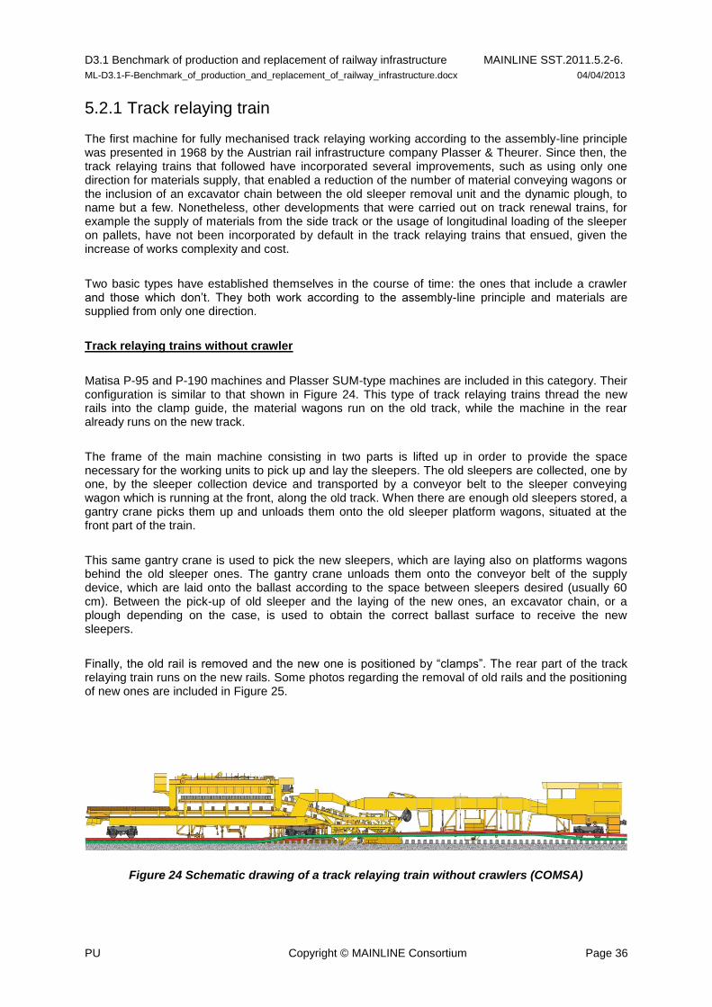
D3.1 Benchmark of production and replacement of railway infrastructure MAINLINE SST.2011.5.2-6.
ML-D3.1-F-Benchmark_of_production_and_replacement_of_railway_infrastructure.docx 04/04/2013
PU Copyright © MAINLINE Consortium Page 36
5.2.1 Track relaying train
The first machine for fully mechanised track relaying working according to the assembly-line principle was presented in 1968 by the Austrian rail infrastructure company Plasser & Theurer. Since then, the track relaying trains that followed have incorporated several improvements, such as using only one direction for materials supply, that enabled a reduction of the number of material conveying wagons or the inclusion of an excavator chain between the old sleeper removal unit and the dynamic plough, to name but a few. Nonetheless, other developments that were carried out on track renewal trains, for example the supply of materials from the side track or the usage of longitudinal loading of the sleeper on pallets, have not been incorporated by default in the track relaying trains that ensued, given the increase of works complexity and cost.
Two basic types have established themselves in the course of time: the ones that include a crawler and those which don’t. They both work according to the assembly-line principle and materials are supplied from only one direction.
Track relaying trains without crawler
Matisa P-95 and P-190 machines and Plasser SUM-type machines are included in this category. Their configuration is similar to that shown in Figure 24. This type of track relaying trains thread the new rails into the clamp guide, the material wagons run on the old track, while the machine in the rear already runs on the new track.
The frame of the main machine consisting in two parts is lifted up in order to provide the space necessary for the working units to pick up and lay the sleepers. The old sleepers are collected, one by one, by the sleeper collection device and transported by a conveyor belt to the sleeper conveying wagon which is running at the front, along the old track. When there are enough old sleepers stored, a gantry crane picks them up and unloads them onto the old sleeper platform wagons, situated at the front part of the train.
This same gantry crane is used to pick the new sleepers, which are laying also on platforms wagons behind the old sleeper ones. The gantry crane unloads them onto the conveyor belt of the supply device, which are laid onto the ballast according to the space between sleepers desired (usually 60 cm). Between the pick-up of old sleeper and the laying of the new ones, an excavator chain, or a plough depending on the case, is used to obtain the correct ballast surface to receive the new sleepers.
Finally, the old rail is removed and the new one is positioned by “clamps”. The rear part of the track relaying train runs on the new rails. Some photos regarding the removal of old rails and the positioning of new ones are included in Figure 25.
Figure 24 Schematic drawing of a track relaying train without crawlers (COMSA)

D3.1 Benchmark of production and replacement of railway infrastructure MAINLINE SST.2011.5.2-6.
ML-D3.1-F-Benchmark_of_production_and_replacement_of_railway_infrastructure.docx 04/04/2013
PU Copyright © MAINLINE Consortium Page 37
Figure 25 Track relaying train without crawlers on operation (COMSA)
The advantages of this type of machine are summarized below:
- They can be used in station areas and on bridges without any problem, as it does not apply crawler devices.
- The lifting of the frame implies lower versines (rail deflections) in the working area.
- They can be adapted to integrate ballast cleaning (this will lead to the new RU 800 S machine of Plasser combining track renewal and ballast cleaning, which is described in section 4.2.3).
Track relaying trains with crawler
Plasser SUZ type machines (similar to SMD trains) are included in this category. A schematic drawing of this type of track relaying trains is presented in Figure 26. This machine also consists of two parts which are lifted up for working, but which normally run on a three-axle bogie transfer.
The front part of the machine runs on a crawler. The sleeper collection device is arranged in front of the crawler. Immediately behind the crawler an excavation chain picks up the ballast, regulates it and deposits it via cross conveyor belts alternatively on the left or right hand side. For minor lowering values (up to 50 mm) a plough is arranged behind the excavation chain which may be used alternatively to the excavation chain. The sleeper conveying wagon is located behind the machine on the old track. Two plate consolidators compact the ballast formation in the area of the sleeper supports. The track laying device lays two sleepers at the same time.

D3.1 Benchmark of production and replacement of railway infrastructure MAINLINE SST.2011.5.2-6.
ML-D3.1-F-Benchmark_of_production_and_replacement_of_railway_infrastructure.docx 04/04/2013
PU Copyright © MAINLINE Consortium Page 38
The only factor restricting the speed of the machine is the material supply. The material is delivered by gantry cranes. The gantry crane of the main machine transfers the new sleepers to the chain belt of the supply device. The other gantry crane delivers the new sleepers, picks up the old sleepers and stores them on the material wagon. Apart from the devices mentioned above, the relaying train is equipped with other auxiliary devices, such as the sleeper ejecting device used to remove broken sleepers to the side, a hydraulic rail pulling device for longitudinal positioning of the new rails, and shoulder ploughs which move the ballast towards the new sleepers.
This type of track relaying train allows the new rails to be brought forwards in a smooth curve. Another gang can fasten the rails to the sleepers independently of the relaying machine. For disassembling the old track the working direction is reversed. The sleeper collection device has to be modified correspondingly for this purpose and its position has to be changed. An alternative technology which has a positive effect on the performance is to disassemble the old rails and to load them on a rail loading train directly in front of the relaying train.
This kind of track relaying train can be equipped with a rail pulling and pushing device. This device enables new rails to be transported together with the machine so that it is no longer necessary to previously deposit them. The rail pushing device moves the rails forwards and the relaying train lays them. The rail conveying wagons are arranged behind the sleeper transportation wagons. Another option is to pick up the old rails and unload them onto the rail transportation wagons running together with the machine. In this case, the rail pulling device is arranged in front of the relaying train and runs on the new track; see [11] Lichtberger (2011).
The advantages of this type of machines are summarized below:
- The new rails are installed with a minimum stress.
- The crawler support enables to use the machine for track laying also. In this case, the working direction is reversed and the machine travels on the ballast with its front part.
- The crawler provides a high towing force for the movement of the machine including the sleeper carrying wagons.
Modern Railway Track; see [10] Esveld (2001).
Figure 26 SUZ (cf. ETR 03/2004)
5.2.2 Ballast cleaning machine
A lot of different versions of ballast cleaning machines can be found, but what they have in common is the way the process works. They are equipped with a track lifting and slewing device that allows the track to be lifted to reduce the cutting depth when required, and to be shifted laterally as required to clear track side obstacles. The excavator chain takes the material directly to the screening unit, which is a hydraulically driven shaker assembly with screens separating waste and ballast. A system of conveyors transports the waste material to the end of the machine, where it is discharged. The cleaned ballast is mixed with the pre-dumped, picked-up and stored ballast and put back to the track directly behind the cutter chain. When working in curves, the shaker boxes can be adjusted to compensate for superelevation (Plasser & Theurer).
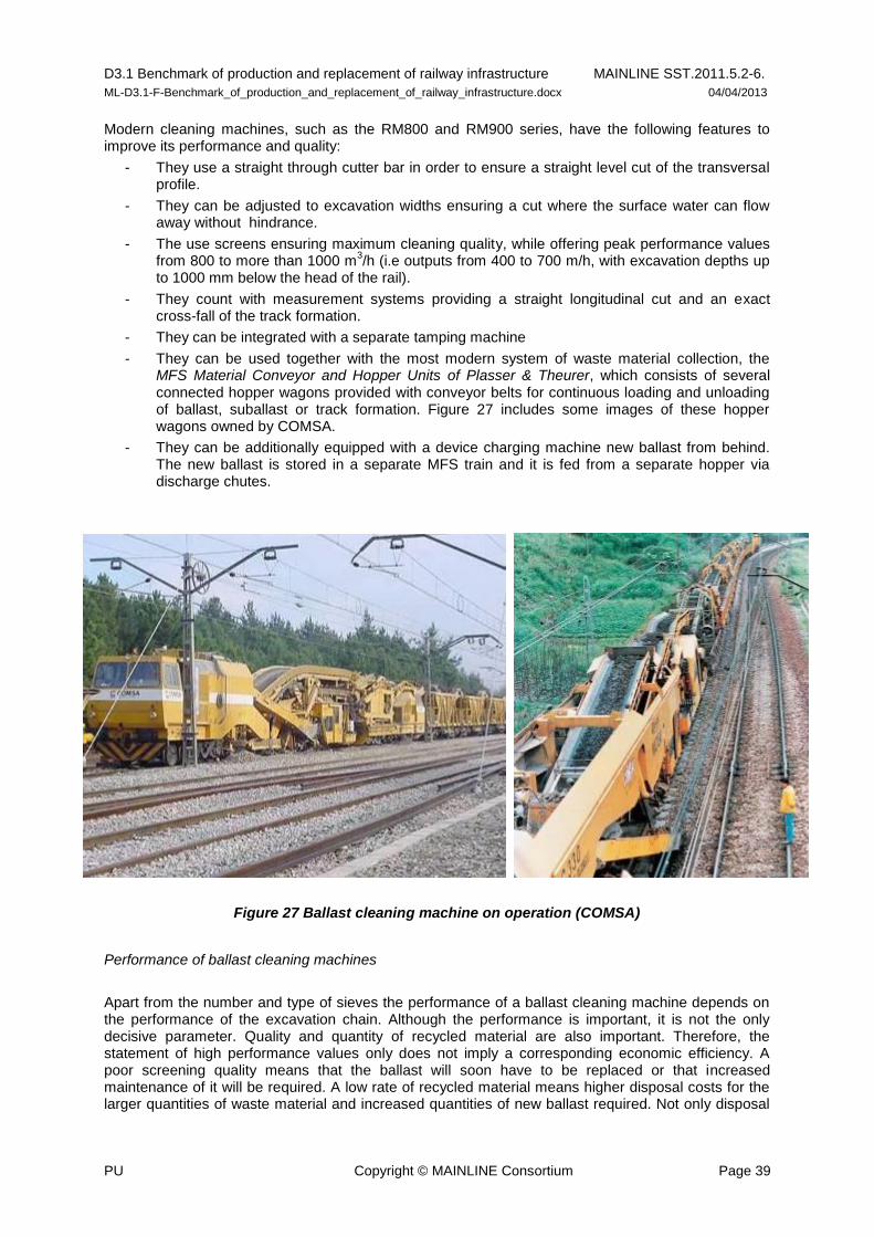
D3.1 Benchmark of production and replacement of railway infrastructure MAINLINE SST.2011.5.2-6.
ML-D3.1-F-Benchmark_of_production_and_replacement_of_railway_infrastructure.docx 04/04/2013
PU Copyright © MAINLINE Consortium Page 39
Modern cleaning machines, such as the RM800 and RM900 series, have the following features to improve its performance and quality:
- They use a straight through cutter bar in order to ensure a straight level cut of the transversal profile.
- They can be adjusted to excavation widths ensuring a cut where the surface water can flow away without hindrance.
- The use screens ensuring maximum cleaning quality, while offering peak performance values from 800 to more than 1000 m
3/h (i.e outputs from 400 to 700 m/h, with excavation depths up
to 1000 mm below the head of the rail).
- They count with measurement systems providing a straight longitudinal cut and an exact cross-fall of the track formation.
- They can be integrated with a separate tamping machine
- They can be used together with the most modern system of waste material collection, the MFS Material Conveyor and Hopper Units of Plasser & Theurer, which consists of several connected hopper wagons provided with conveyor belts for continuous loading and unloading of ballast, suballast or track formation. Figure 27 includes some images of these hopper wagons owned by COMSA.
- They can be additionally equipped with a device charging machine new ballast from behind. The new ballast is stored in a separate MFS train and it is fed from a separate hopper via discharge chutes.
Figure 27 Ballast cleaning machine on operation (COMSA)
Performance of ballast cleaning machines
Apart from the number and type of sieves the performance of a ballast cleaning machine depends on the performance of the excavation chain. Although the performance is important, it is not the only decisive parameter. Quality and quantity of recycled material are also important. Therefore, the statement of high performance values only does not imply a corresponding economic efficiency. A poor screening quality means that the ballast will soon have to be replaced or that increased maintenance of it will be required. A low rate of recycled material means higher disposal costs for the larger quantities of waste material and increased quantities of new ballast required. Not only disposal
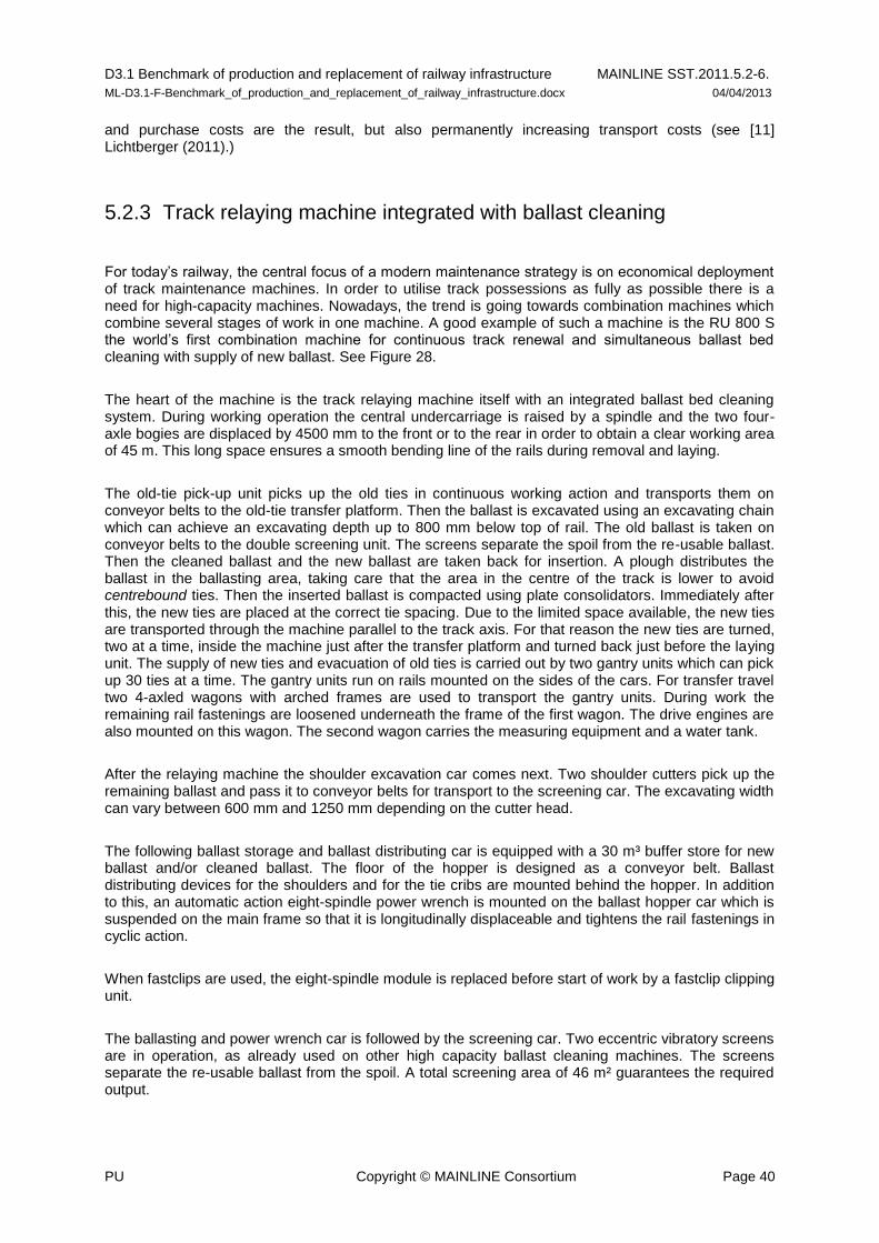
D3.1 Benchmark of production and replacement of railway infrastructure MAINLINE SST.2011.5.2-6.
ML-D3.1-F-Benchmark_of_production_and_replacement_of_railway_infrastructure.docx 04/04/2013
PU Copyright © MAINLINE Consortium Page 40
and purchase costs are the result, but also permanently increasing transport costs (see [11] Lichtberger (2011).)
5.2.3 Track relaying machine integrated with ballast cleaning
For today’s railway, the central focus of a modern maintenance strategy is on economical deployment of track maintenance machines. In order to utilise track possessions as fully as possible there is a need for high-capacity machines. Nowadays, the trend is going towards combination machines which combine several stages of work in one machine. A good example of such a machine is the RU 800 S the world’s first combination machine for continuous track renewal and simultaneous ballast bed cleaning with supply of new ballast. See Figure 28.
The heart of the machine is the track relaying machine itself with an integrated ballast bed cleaning system. During working operation the central undercarriage is raised by a spindle and the two four-axle bogies are displaced by 4500 mm to the front or to the rear in order to obtain a clear working area of 45 m. This long space ensures a smooth bending line of the rails during removal and laying.
The old-tie pick-up unit picks up the old ties in continuous working action and transports them on conveyor belts to the old-tie transfer platform. Then the ballast is excavated using an excavating chain which can achieve an excavating depth up to 800 mm below top of rail. The old ballast is taken on conveyor belts to the double screening unit. The screens separate the spoil from the re-usable ballast. Then the cleaned ballast and the new ballast are taken back for insertion. A plough distributes the ballast in the ballasting area, taking care that the area in the centre of the track is lower to avoid centrebound ties. Then the inserted ballast is compacted using plate consolidators. Immediately after this, the new ties are placed at the correct tie spacing. Due to the limited space available, the new ties are transported through the machine parallel to the track axis. For that reason the new ties are turned, two at a time, inside the machine just after the transfer platform and turned back just before the laying unit. The supply of new ties and evacuation of old ties is carried out by two gantry units which can pick up 30 ties at a time. The gantry units run on rails mounted on the sides of the cars. For transfer travel two 4-axled wagons with arched frames are used to transport the gantry units. During work the remaining rail fastenings are loosened underneath the frame of the first wagon. The drive engines are also mounted on this wagon. The second wagon carries the measuring equipment and a water tank.
After the relaying machine the shoulder excavation car comes next. Two shoulder cutters pick up the remaining ballast and pass it to conveyor belts for transport to the screening car. The excavating width can vary between 600 mm and 1250 mm depending on the cutter head.
The following ballast storage and ballast distributing car is equipped with a 30 m³ buffer store for new ballast and/or cleaned ballast. The floor of the hopper is designed as a conveyor belt. Ballast distributing devices for the shoulders and for the tie cribs are mounted behind the hopper. In addition to this, an automatic action eight-spindle power wrench is mounted on the ballast hopper car which is suspended on the main frame so that it is longitudinally displaceable and tightens the rail fastenings in cyclic action.
When fastclips are used, the eight-spindle module is replaced before start of work by a fastclip clipping unit.
The ballasting and power wrench car is followed by the screening car. Two eccentric vibratory screens are in operation, as already used on other high capacity ballast cleaning machines. The screens separate the re-usable ballast from the spoil. A total screening area of 46 m² guarantees the required output.

D3.1 Benchmark of production and replacement of railway infrastructure MAINLINE SST.2011.5.2-6.
ML-D3.1-F-Benchmark_of_production_and_replacement_of_railway_infrastructure.docx 04/04/2013
PU Copyright © MAINLINE Consortium Page 41
Material conveyor and hopper units are used to transport the spoil and the ballast. These are coupled to the end of the machine. To transport the spoil, the new-ballast MFS is equipped additionally with a conveyor belt. (Plasser & Theurer)
Figure 28 RU 800 S (cf. Plasser & Theurer)
5.2.4 Gantry crane method
There are two variants of the gantry crane method. In the first one, assembled track sections are installed. In the second version, which is mainly concerned with CWR track, only the sleepers are laid and directly afterwards the rails are placed onto them. The latter method is used most widely in Europe and because of that, it is described in this section. See also Figure 29.
In first place the old rails are cut every 30 m so as to obtain track segments of that length, which are lifted by the gantry cranes and unloaded on platform wagons. These cranes run on temporary rails which are laid on either side of the track and that have been unloaded on a previous shift.
The ballast is removed by excavators (although it is also possible to simply adequate the ballast surface, if the ballast cleaning is not required).
Once the ballast layer has been removed, the gantry cranes load the new sleepers from the platform wagons and unload them onto the ballast layer. The unloading is done in two phases to place them at the correct distance (around 60 cm).
After the unloading of sleepers, rails are positioned by a rail threader, the fasteners are tightened and the rails are welded. And finally, the new ballast is discharged by a ballast train running on the new track and followed by a tamping and stabilizing machine.
Track is divided in “sections or
panels” by cutting the rail
Crane lift the old “panels” and
unload them on platforms
Crane lift sleepers from train
platforms
Sleepers are unloaded in two
steps.
Rail is positioned with rail
threaders
Ballast is discharged, followed
by tamping and stabilisation
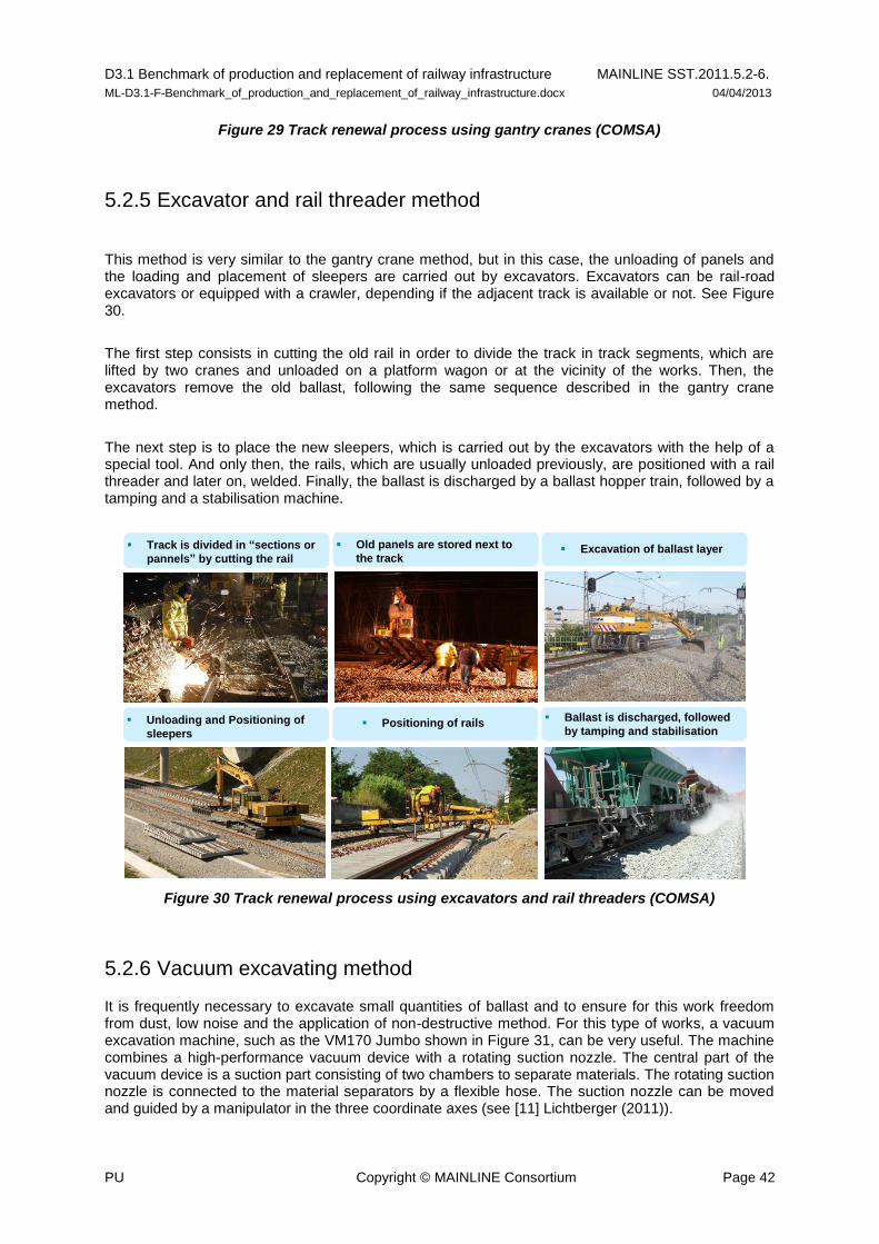
D3.1 Benchmark of production and replacement of railway infrastructure MAINLINE SST.2011.5.2-6.
ML-D3.1-F-Benchmark_of_production_and_replacement_of_railway_infrastructure.docx 04/04/2013
PU Copyright © MAINLINE Consortium Page 42
Figure 29 Track renewal process using gantry cranes (COMSA)
5.2.5 Excavator and rail threader method
This method is very similar to the gantry crane method, but in this case, the unloading of panels and the loading and placement of sleepers are carried out by excavators. Excavators can be rail-road excavators or equipped with a crawler, depending if the adjacent track is available or not. See Figure 30.
The first step consists in cutting the old rail in order to divide the track in track segments, which are lifted by two cranes and unloaded on a platform wagon or at the vicinity of the works. Then, the excavators remove the old ballast, following the same sequence described in the gantry crane method.
The next step is to place the new sleepers, which is carried out by the excavators with the help of a special tool. And only then, the rails, which are usually unloaded previously, are positioned with a rail threader and later on, welded. Finally, the ballast is discharged by a ballast hopper train, followed by a tamping and a stabilisation machine.
Figure 30 Track renewal process using excavators and rail threaders (COMSA)
5.2.6 Vacuum excavating method
It is frequently necessary to excavate small quantities of ballast and to ensure for this work freedom from dust, low noise and the application of non-destructive method. For this type of works, a vacuum excavation machine, such as the VM170 Jumbo shown in Figure 31, can be very useful. The machine combines a high-performance vacuum device with a rotating suction nozzle. The central part of the vacuum device is a suction part consisting of two chambers to separate materials. The rotating suction nozzle is connected to the material separators by a flexible hose. The suction nozzle can be moved and guided by a manipulator in the three coordinate axes (see [11] Lichtberger (2011)).
Track is divided in “sections or
pannels” by cutting the rail
Old panels are stored next to
the track Excavation of ballast layer
Unloading and Positioning of
sleepers Positioning of rails
Ballast is discharged, followed
by tamping and stabilisation

D3.1 Benchmark of production and replacement of railway infrastructure MAINLINE SST.2011.5.2-6.
ML-D3.1-F-Benchmark_of_production_and_replacement_of_railway_infrastructure.docx 04/04/2013
PU Copyright © MAINLINE Consortium Page 43
Figure 31 Vaccum excavator machine Jumbo (cf. Plasser & Theurer)
5.2.7 Formation rehabilitation machines
Formation rehabilitation machines permit to avoid manual insertion of sand blankets which is not only costly and time-consuming, but also results in a deficient quality (the compactness and uniformity of the blanket cannot be maintained).
There are different machines and machine systems that allow the insertion of sand blankets, geosynthetics or other protection layers under the track, in track possessions, without the necessity to dismantle the track. However, only two machines will be described here (AHM 800R and PM 1000 URM) since they are the most known among the latest design machines (see [10] Esveld (2001))
AHM 800R machine – Incorporating ballast recycling
The AHM 800 R is used for formation rehabilitation. Therefore the top layer of ballast has to be removed by the first excavation chain and transported to the crushing plant. Metal parts are eliminated on a magnetic conveyor belt. The three-stage crushing plant crushed the recycled ballast according to a defined grain size curve. A gantry crane together with an intermediary storage bin supply new sand gravel material from behind. The new material, the sand-gravel mix, as well as the recycled ballast material comes together in the mixing device. The material is mixed and optionally prepared for a good compaction bay artificial wetting and is then transported into the sand distribution and compaction unit.
The second excavation chain excavates the remaining ballast bed material and transports it on a conveyor belt to the Material Conveyor and Hopper Units MFS in front. A formation levelling and geotextile, geogrid and PU-plate insertion device is arranged behind the second excavation chain. For total ballast bed excavation and simultaneous insertion of a formation protective device with a thickness of up to 50 cm and recycling of track ballast, the output achieved is up to 40 m/h. The maximum working advance speed to be expected is – depending on the thickness of the layer – up to 80 m/h (see [11] Lichtberger (2011)). A scheme of AHM 800R machine is presented in Figure 32.
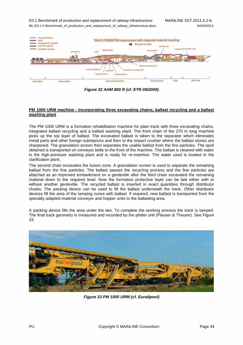
D3.1 Benchmark of production and replacement of railway infrastructure MAINLINE SST.2011.5.2-6.
ML-D3.1-F-Benchmark_of_production_and_replacement_of_railway_infrastructure.docx 04/04/2013
PU Copyright © MAINLINE Consortium Page 44
Figure 32 AHM 800 R (cf. ETR 09/2000)
PM 1000 URM machine - Incorporating three excavating chains, ballast recycling and a ballast washing plant
The PM 1000 URM is a formation rehabilitation machine for plain track with three excavating chains, integrated ballast recycling and a ballast washing plant. The front chain of the 270 m long machine picks up the top layer of ballast. The excavated ballast is taken to the separator which eliminates metal parts and other foreign substances and then to the impact crusher where the ballast stones are sharpened. The granulation screen then separates the usable ballast from the fine particles. The spoil obtained is transported on conveyor belts to the front of the machine. The ballast is cleaned with water in the high-pressure washing plant and is ready for re-insertion. The water used is treated in the clarification plant.
The second chain excavates the fusion zone. A granulation screen is used to separate the remaining ballast from the fine particles. The ballast passes the recycling process and the fine particles are attached as an improved embankment on a geotextile after the third chain excavated the remaining material down to the required level. Now the formation protective layer can be laid either with or without another geotextile. The recycled ballast is inserted in exact quantities through distributor chutes. The packing device can be used to fill the ballast underneath the track. Other distributor devices fill the area of the tamping zones with ballast. If required, new ballast is transported from the specially adapted material conveyor and hopper units to the ballasting area.
A packing device fills the area under the ties. To complete the working process the track is tamped. The final track geometry is measured and recorded by the plotter unit (Plasser & Theurer). See Figure 33.
Figure 33 PM 1000 URM (cf. Eurailpool)

D3.1 Benchmark of production and replacement of railway infrastructure MAINLINE SST.2011.5.2-6.
ML-D3.1-F-Benchmark_of_production_and_replacement_of_railway_infrastructure.docx 04/04/2013
PU Copyright © MAINLINE Consortium Page 45
5.2.8 Puscal method
The PUSCAL method divides a track section into 18 m long parts. The track grid of these parts is loaded onto a wagon by gantry cranes and replaced by temporary rails connected by tie rods. A spiral cutter to excavate the material and funnel wagons to transport the soil away enters this track section from the other end. After the soil has been compacted, the ballast is inserted and finally gantry cranes relay the track panels. This method achieves a performance of about 18m/h, it requires track closures of at least 20 hours (see [11] Lichtberger (2011)). See Figure 34.
Figure 34 PUSCAL IV (cf. rail.lu)
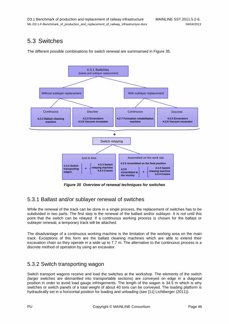
D3.1 Benchmark of production and replacement of railway infrastructure MAINLINE SST.2011.5.2-6.
ML-D3.1-F-Benchmark_of_production_and_replacement_of_railway_infrastructure.docx 04/04/2013
PU Copyright © MAINLINE Consortium Page 46
5.3 Switches
The different possible combinations for switch renewal are summarised in Figure 35.
Figure 35 Overview of renewal techniques for switches
5.3.1 Ballast and/or sublayer renewal of switches
While the renewal of the track can be done in a single process, the replacement of switches has to be subdivided in two parts. The first step is the renewal of the ballast and/or sublayer. It is not until this point that the switch can be relayed. If a continuous working process is chosen for the ballast or sublayer renewal, a temporary track will be attached.
The disadvantage of a continuous working machine is the limitation of the working area on the main track. Exceptions of this form are the ballast cleaning machines which are able to extend their excavation chain so they operate in a wide up to 7.7 m. The alternative to the continuous process is a discrete method of operation by using an excavator.
5.3.2 Switch transporting wagon
Switch transport wagons receive and load the switches at the workshop. The elements of the switch (larger switches are dismantled into transportable sections) are conveyed on edge in a diagonal position in order to avoid load gauge infringements. The length of the wagon is 34.5 m which is why switches or switch panels of a total weight of about 40 tons can be conveyed. The loading platform is hydraulically set in a horizontal position for loading and unloading (see [11] Lichtberger (2011)).
4.3.1 Switches(balast and sublayer replacement)
Without sublayer replacement
Continuous
4.2.5 Excavators
4.2.6 Vacuum excavator
Discrete
4.2.2 Ballast cleaning
machine
With sublayer replacement
Continuous Discrete
4.2.7 Formation rehabilitation
machine
4.2.5 Excavators
4.2.6 Vacuum excavator
Switch relaying
Just in time
4.3.5 Assembled on the final position4.3.2 Switch
transporting
wagon
Assembled on the work site
4.3.3 Switch
relaying machine
4.3.4 Cranes4.3.6
Assembled at
the vicinity
4.3.3 Switch
relaying machine
4.3.4 Cranes
+ +
+

D3.1 Benchmark of production and replacement of railway infrastructure MAINLINE SST.2011.5.2-6.
ML-D3.1-F-Benchmark_of_production_and_replacement_of_railway_infrastructure.docx 04/04/2013
PU Copyright © MAINLINE Consortium Page 47
5.3.3 Switch relaying machine
There are many different types of switch relaying machines. However, they have many similarities: they usually run on crawlers, they are equipped with a longitudinal metallic beam and their installation process is very similar. One of the main differences between switch relaying machines is the possibility or not to move in any direction. There are machines, such as DESEC TL-70 machine shown in Figure 36, whose crawlers can rotate to achieve the desired direction, whilst other only admit a unique direction of movement.
Figure 36 Switch relaying machine with orientable crawlers (cf. DESEC)
As mentioned above, the methodology of work of these machines is very similar. In this section, the process of switch relaying explained corresponds to the WM 500 machines used jointly with WTW wagons.
WM 500 switch relaying machine in combination with WTW transportation wagon
The WM 500 switch relaying machine allows the installation and removal of turnouts, parts of a turnout or track panels. It consists of a hydraulic lifting device with a lifting capacity of up to 70 tons. This machine enables concrete sleeper switches with a curve radius of 500 m to be laid in one piece. As the lifting device is equipped with a torsion-proof longitudinal beam and corresponding cross beams, the switches or the switch panels are lifted and lowered evenly. The three degrees of freedom of the loading device enable the switch to be positioned exactly. The position of the switch is stable, as it is not suspended on a crane hook which might sway. Furthermore, no dynamic impact occurs, which also might change the high quality of the switch geometry. The entire machine system can be controlled by one operator. The total start-up and close down periods can be half the ones compared to traditional methods.
The lifting device together with the transportation wagon, described in the previous section, is brought to the switch (or switch panel) to be dismantled. See Figure 37. Here, the jack is extended and supported on the ballast bed. The transportation car drives away and the switch (or switch panel) is lifted. Then the transportation wagon on crawlers approaches again on the ballast bed under the lifted switch. The lifting device together with the switch is automatically loaded onto the transportation wagon which then drives away. Its bogies are rerailed onto the adjacent track and the crawler mechanisms are retracted. The switch is unloaded in a suitable place. When the new switch is laid the wagon transporting the switch and the crawler approaches on the track formation. The switch is lifted off the transportation wagon, the lifting device being again supported on the ballast. The transportation wagon drives away, the new switch is deposited in the track. Afterwards the transportation wagon

D3.1 Benchmark of production and replacement of railway infrastructure MAINLINE SST.2011.5.2-6.
ML-D3.1-F-Benchmark_of_production_and_replacement_of_railway_infrastructure.docx 04/04/2013
PU Copyright © MAINLINE Consortium Page 48
enters the area on the rails, the lifting device is loaded onto it and moves away (see [11] Lichtberger (2011)).
Figure 37 Switch relaying machine WM 500 U and switch transportation wagon WTW (cf. Plasser & Theurer)
5.3.4 Switch relaying by cranes
The characteristic feature of switch relaying using cranes is that it is not possible to move an entire switch. As the bearing capacity of these cranes is limited, the switch has to be dismantled. It is divided into three parts: the blade part, the central part and the diamond part. Larger switches are relaid by two cranes from the adjacent track. High-performance cranes can disassemble and relay switches with radii of 760 m in front of the cranes and under live overhead wires. The adjacent track has to be closed during the lifting procedures (see [11] Lichtberger (2011)). See Figure 38.
Figure 38 Switch relaying by crane (cf. Marx, Moßmann; 2011)
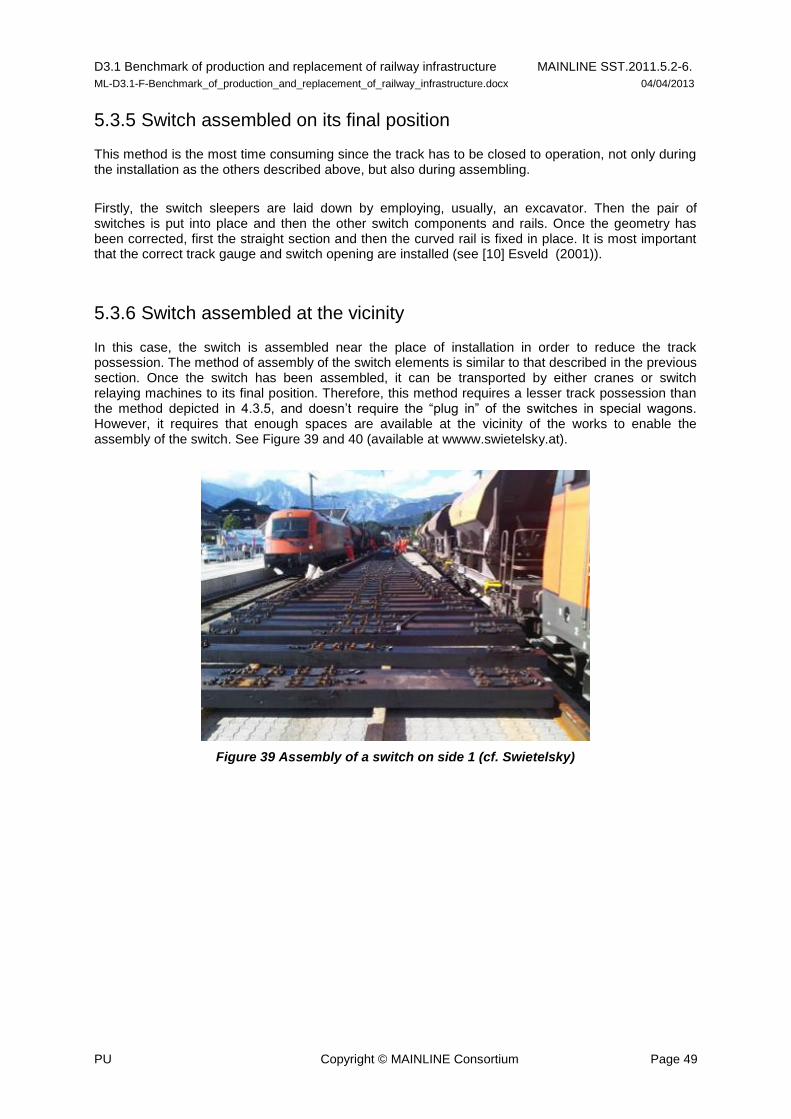
D3.1 Benchmark of production and replacement of railway infrastructure MAINLINE SST.2011.5.2-6.
ML-D3.1-F-Benchmark_of_production_and_replacement_of_railway_infrastructure.docx 04/04/2013
PU Copyright © MAINLINE Consortium Page 49
5.3.5 Switch assembled on its final position
This method is the most time consuming since the track has to be closed to operation, not only during the installation as the others described above, but also during assembling.
Firstly, the switch sleepers are laid down by employing, usually, an excavator. Then the pair of switches is put into place and then the other switch components and rails. Once the geometry has been corrected, first the straight section and then the curved rail is fixed in place. It is most important that the correct track gauge and switch opening are installed (see [10] Esveld (2001)).
5.3.6 Switch assembled at the vicinity
In this case, the switch is assembled near the place of installation in order to reduce the track possession. The method of assembly of the switch elements is similar to that described in the previous section. Once the switch has been assembled, it can be transported by either cranes or switch relaying machines to its final position. Therefore, this method requires a lesser track possession than the method depicted in 4.3.5, and doesn’t require the “plug in” of the switches in special wagons. However, it requires that enough spaces are available at the vicinity of the works to enable the assembly of the switch. See Figure 39 and 40 (available at wwww.swietelsky.at).
Figure 39 Assembly of a switch on side 1 (cf. Swietelsky)
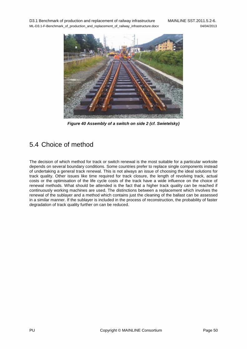
D3.1 Benchmark of production and replacement of railway infrastructure MAINLINE SST.2011.5.2-6.
ML-D3.1-F-Benchmark_of_production_and_replacement_of_railway_infrastructure.docx 04/04/2013
PU Copyright © MAINLINE Consortium Page 50
Figure 40 Assembly of a switch on side 2 (cf. Swietelsky)
5.4 Choice of method
The decision of which method for track or switch renewal is the most suitable for a particular worksite depends on several boundary conditions. Some countries prefer to replace single components instead of undertaking a general track renewal. This is not always an issue of choosing the ideal solutions for track quality. Other issues like time required for track closure, the length of revolving track, actual costs or the optimisation of the life cycle costs of the track have a wide influence on the choice of renewal methods. What should be attended is the fact that a higher track quality can be reached if continuously working machines are used. The distinctions between a replacement which involves the renewal of the sublayer and a method which contains just the cleaning of the ballast can be assessed in a similar manner. If the sublayer is included in the process of reconstruction, the probability of faster degradation of track quality further on can be reduced.

D3.1 Benchmark of production and replacement of railway infrastructure MAINLINE SST.2011.5.2-6.
ML-D3.1-F-Benchmark_of_production_and_replacement_of_railway_infrastructure.docx 04/04/2013
PU Copyright © MAINLINE Consortium Page 51
6. Conclusion
6.1 Main findings
A European survey has been carried out regarding methods for reconstruction of bridge structures and replacement for track systems. One can see that there are many similar good and reliable methods for replacement that are more or less used all over Europe. The main differences are due to construction planning and the necessary logistics for the management of each specific site.
In some countries or infrastructure networks no or only very short track possessions are available. The reasons for this are numerous including:
high penalties against the railway company,
very dense traffic and/or no rerouting possible.
In these situations, very expensive construction methods are used to be able to reopen the track quickly. In other countries time boundaries can be solved differently as deviations together with longer travel times are accepted for the construction period. In some cases bus traffic is used instead of rail. The main parameter is the available track possession; this strongly limits the methods available.
For track renewal, it can be evidenced that the replacement of single components of the track only helps to improve track quality for a very short period of time. A further more extensive exchange will be necessary afterwards to maintain the track condition. With respect to the overall life cycle cost for a line this fact has to be seen as very critical and the costs should be looked at closely. In most cases a single time-consuming and expensive intervention is recommended at lower frequency.
Conversely, partial replacement of superstructures or replacement of the bridge deck represents a more economical way to improve the network quality and availability in a short time than full reconstruction of the abutments for a bridge structure, achieving the necessary condition for a long life.
The boundary conditions of the structure and the importance of the line are the governing factors for selection of method and technology. This report considers a number of the available boundaries conditions and site parameters of a railway construction site to aid in decision making.
The presented methods will help European Infrastructure Managers to identify the method that is the most appropriate for their specific construction problem. One can decide between several finished conditions that can be reached. Furthermore this report shows well known and adequate methods that are extensively proven from many construction companies all over Europe. Eastern European countries may find well known methods not yet used in their networks to improve maintenance of the railway network.
D3.1 Benchmark of production and replacement of railway infrastructure MAINLINE SST.2011.5.2-6.
ML-D3.1-F-Benchmark_of_production_and_replacement_of_railway_infrastructure.docx 04/04/2013
PU Copyright © MAINLINE Consortium Page 52
References
[1] ML-D1.1 (2012): Benchmark of new technologies to extend the life of elderly rail infrastructure
http://www.mainline-project.eu/
[2] “MAINLINE Benchmarking Procedures and Framework” produced by SKM.
[3] Sustainable Bridges, Deliverable D1.2 European Bridge Demography; 2003, 15 pp. Available
at www.sustainablebridges.net
[4] Pfeifer, Rolf H. and Mölter, Tristan, M (2008): Handbuch Eisenbahnbrücken (Handbook
Railway Bridges: In German). Eurail Press, 376 pp, ISBN 978-3-7771-0378-5
[5] Verband öffentlicher Verkehr (2004): Hilfsbrücken für Eisenbahnen (Temporary Bridges for
Railways. In German). Switzerland, SBB Richtlinie R RTE 21590
[6] Koch, Karl-Fridrich (1997): Hilfsbrücken. Werner Verlag, 148 üpp, ISBN 978-3-8041-4920-5
[7] Bayoglu Flener, Esra (2009): Static and dynamic behaviour of soil-steel composite bridges obtained by field testing. Ph D, Thesis Royal Institute of Technology, Stockholm, Sweden, TRITA-BKN. Bulletin 98, 2007, ISSN 1103-4270, ISRN KTH/BKN/B--98—SE. Report on in-situ measurements and data analyses for the performance tests during backfilling and after completion of a long span corrugated steel culvert railway bridge over Skivarpsån, Rydsgård, Sweden
[8] Pettersson, Lars (2007): Full Scale Test and Structural Evaluation of Soil Steel Flexible Culverts with Low Height of Cover, Ph D Thesis, Royal Institute of Technology, Stockholm, Sweden, TRITA-BKN. Bulletin 93, 2007, ISSN 1103-4270, ISRN KTH/BKN/B--93—SE.
[9] Canning, Lee (2012): Development in FRP railway bridge applications; Sinclair Knight Mertz (SKM). Personal communication.
[10] Esveld, Coenrrad (2001): Modern Rail Technology, Delft University of Technology, 2nd
Ed, 629 pp, ISBN 90-800324-3-3. An excerpt of 87pp can be downloaded from http://www.esveld.com/MRT_Selection.pdf
[11] Lichtberger Bernard (2005): Track Compendium. Track Sytem-Substructure-Maintenance-economics. Eurail Press 2
nd Ed, 622 pp, ISBN 978-3-7771-0421-8. (Originally in German as
“Handbuch Gleis”, 3rd
Ed, 2010. 656 pp, ISBN 978-3-7771-0400-3.)

D3.1 Benchmark of production and replacement of railway infrastructure MAINLINE SST.2011.5.2-6.
ML-D3.1-F-Benchmark_of_production_and_replacement_of_railway_infrastructure.docx 04/04/2013
PU Copyright © MAINLINE Consortium Page 53
Annex 1 – Case studies Bridges
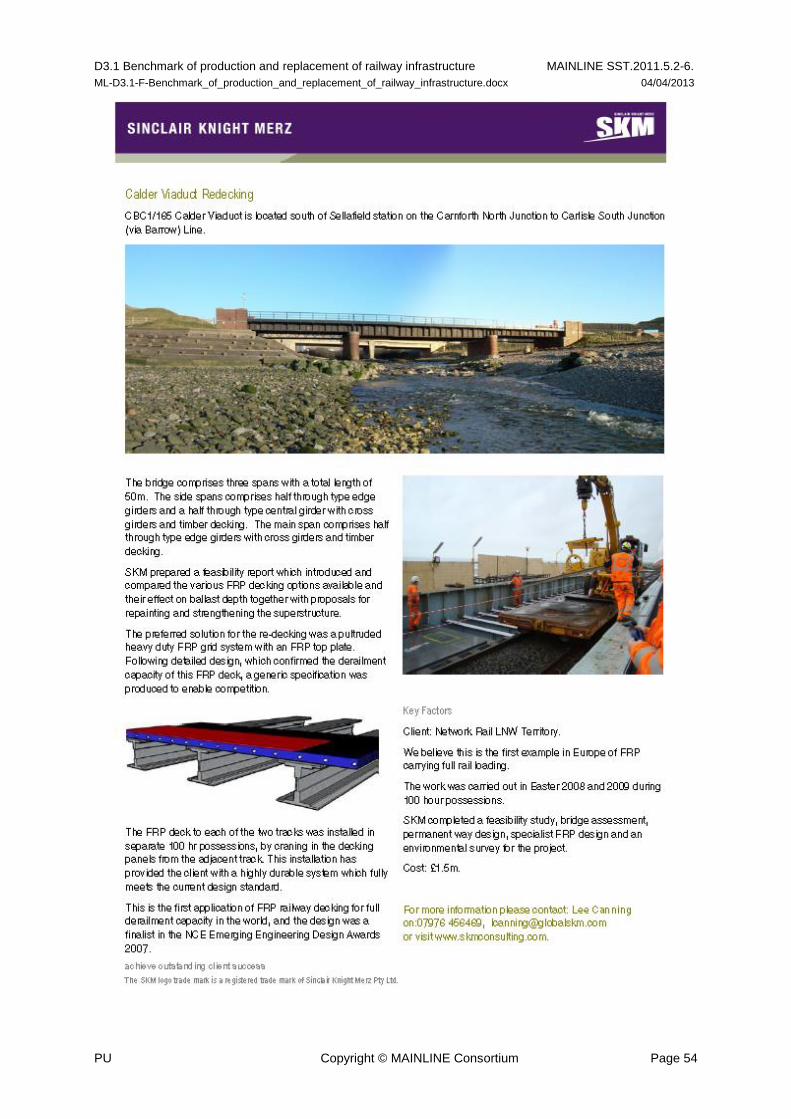
D3.1 Benchmark of production and replacement of railway infrastructure MAINLINE SST.2011.5.2-6.
ML-D3.1-F-Benchmark_of_production_and_replacement_of_railway_infrastructure.docx 04/04/2013
PU Copyright © MAINLINE Consortium Page 54
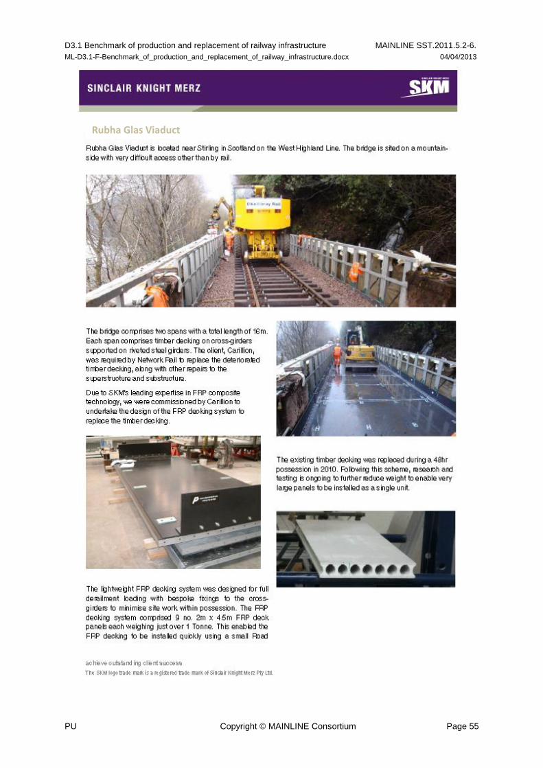
D3.1 Benchmark of production and replacement of railway infrastructure MAINLINE SST.2011.5.2-6.
ML-D3.1-F-Benchmark_of_production_and_replacement_of_railway_infrastructure.docx 04/04/2013
PU Copyright © MAINLINE Consortium Page 55
Rubha Glas Viaduct
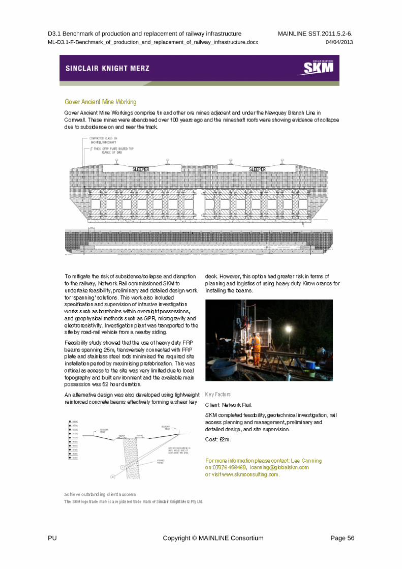
D3.1 Benchmark of production and replacement of railway infrastructure MAINLINE SST.2011.5.2-6.
ML-D3.1-F-Benchmark_of_production_and_replacement_of_railway_infrastructure.docx 04/04/2013
PU Copyright © MAINLINE Consortium Page 56

D3.1 Benchmark of production and replacement of railway infrastructure MAINLINE SST.2011.5.2-6.
ML-D3.1-F-Benchmark_of_production_and_replacement_of_railway_infrastructure.docx 04/04/2013
PU Copyright © MAINLINE Consortium Page 57

D3.1 Benchmark of production and replacement of railway infrastructure MAINLINE SST.2011.5.2-6.
ML-D3.1-F-Benchmark_of_production_and_replacement_of_railway_infrastructure.docx 04/04/2013
PU Copyright © MAINLINE Consortium Page 58