DELIQUIFICATION & REVIVAL OF OIL AND GAS WELLS … · DELIQUIFICATION & REVIVAL OF OIL AND GAS...
33
8 th European Conference on Gas Well De-liquification ,Groningen, 2013 DELIQUIFICATION & REVIVAL OF OIL AND GAS WELLS USING SURFACE JET PUMPS Recent applications and experience Recent applications and experience By: Sacha Sarshar ,Caltec
Transcript of DELIQUIFICATION & REVIVAL OF OIL AND GAS WELLS … · DELIQUIFICATION & REVIVAL OF OIL AND GAS...

8th European Conference on Gas Well De-liquification ,Groningen, 2013
DELIQUIFICATION & REVIVALOF OIL AND GAS WELLS
USING SURFACE JET PUMPSRecent applications and experienceRecent applications and experience
By: Sacha Sarshar ,Caltec
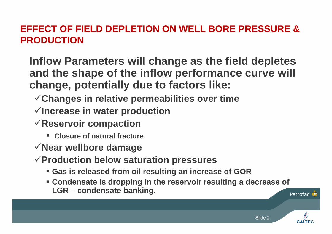
EFFECT OF FIELD DEPLETION ON WELL BORE PRESSURE & PRODUCTIONPRODUCTION
Inflow Parameters will change as the field depletesInflow Parameters will change as the field depletes and the shape of the inflow performance curve will change, potentially due to factors like:g p yChanges in relative permeabilities over timeIncrease in water productionReservoir compaction Closure of natural fracture
Near wellbore damageProduction below saturation pressures
Gas is released from oil resulting an increase of GOR Gas is released from oil resulting an increase of GOR Condensate is dropping in the reservoir resulting a decrease of
LGR – condensate banking.
Slide 2
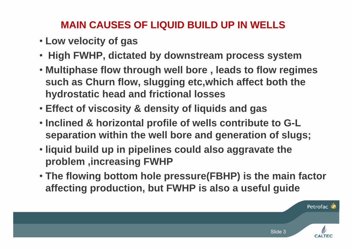
MAIN CAUSES OF LIQUID BUILD UP IN WELLS• Low velocity of gas• Low velocity of gas• High FWHP, dictated by downstream process system
M ltiphase flo thro gh ell bore leads to flo regimes• Multiphase flow through well bore , leads to flow regimes such as Churn flow, slugging etc,which affect both the hydrostatic head and frictional losseshydrostatic head and frictional losses
• Effect of viscosity & density of liquids and gas• Inclined & horizontal profile of wells contribute to G-LInclined & horizontal profile of wells contribute to G L
separation within the well bore and generation of slugs; • liquid build up in pipelines could also aggravate theliquid build up in pipelines could also aggravate the
problem ,increasing FWHP• The flowing bottom hole pressure(FBHP) is the main factor g p ( )
affecting production, but FWHP is also a useful guide
Slide 3
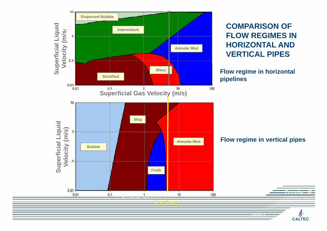
COMPARISON OF FLOW REGIMES IN
Intermittent
Dispersed Bubble
iqui
d m
/s)
FLOW REGIMES IN HORIZONTAL AND VERTICAL PIPES
Annular Mist
erfic
ial L
iel
ocity
(mWavy
Stratified
Sup Ve
Flow regime in horizontal pipelines
Superficial Gas Velocity (m/s)
Slug
Annular Mistl Liq
uid
(m/s
)
Flow regime in vertical pipesAnnular MistBubble
uper
ficia
lVe
loci
ty g p p
FrothSu
V ≥ 5 m/s
Slide 4

COMMON REMEDIAL SOLUTIONS TO WELL DE-IQUIFICATION
• Regular gas blow down to atmosphere• Lower flowing wellhead pressure ( use of jet pump• Lower flowing wellhead pressure ( use of jet pump
technology or other methods)• Well shut-in IntermittentlyWell shut-in Intermittently• Use of foaming agents/intermittent or continuous• Tubing size modification/velocity string• Tubing size modification/velocity string• Artificial lift systems (Downhole) including downhole jet
pumps,ESPs, plunger lift,etc.pumps,ESPs, plunger lift,etc.• Best solution is dictated by well status,resevoir
characteristics, available source of energy, platform , gy, pconstraints and economic consideration
Slide 5

SELECTION PROCESS FOR WELL DELIQUIFICATIONBASED ON SEVERITY OF THE CASE
Case1(Mild) Case 2 (Medium) Case 3 (Sever)
Lowering the FWHP by SJP is sufficient
Well loaded, initial
offloading is needed
Downhole system needed
sufficient
SJP could enhance downhole systemsperformance
Lower FWHP by SJP
Aft i iti l ffl di
Use SJP plus intermittent
performance
After initial offloading offloading
Slide 6

Surface Jet Pump TechnologyPatented Universal Design Ejector / Jet PumpPatented Universal Design Ejector / Jet Pump
Some possible HP sources-;
Removable Nozzle
Removable Mixing tube /Diffuser
Some possible HP sources-;
- HP WELLS (oil or gas wells) - COMPRESSOR RECYCLED GAS
HP GAS FROM PROCESS SYSTEM A SINGLE PHASE (LIQUID) PUMP- HP GAS FROM PROCESS SYSTEM - A SINGLE PHASE (LIQUID) PUMP
- HP LIQUID(OIL,WATER)
Slide 7
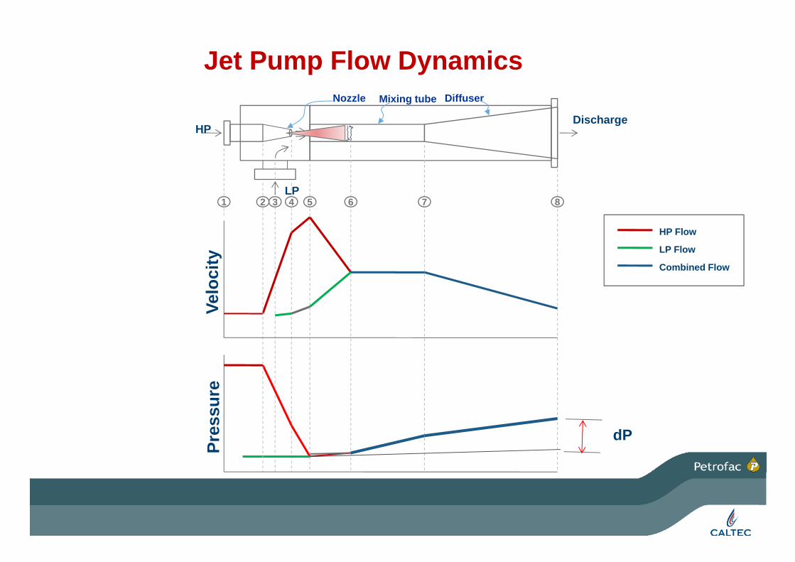
Jet Pump Flow Dynamics
HPDischarge
Nozzle Mixing tube Diffuser
1 3 4 5 6 72 8LP
HP Flow
LP Flow
Combined Flow
ocity
Velo
sure
Pres
s
dP
8

MAIN FACTORS AFFECTING THE PERFORMANCE~ HP/LP PRESSURE RATIO~ HP/LP FLOW RATIO
~ GAS/LIQUID RATIO(LP FLOW)(oil or gas production cases)
Secondary factors;
- Mol. weight
- Temperature
- Liquid in gas- Liquid in gas phase
Slide 9

TYPES AND RANGES OF SJP APPLICATIONS
• Revival of dead wells (oil&gas wells)/ de-liquificationBoost production from oil or gas wells• Boost production from oil or gas wells
• Boost pressure of LP gas in a process system• De-bottleneck compressors• Eliminate intermediate compressorsp• Prevent HP wells impose back pressure on LP wells• Prevent flaring LP gas• Prevent flaring LP gas• Lower back pressure on pipelines/reduce liquid l di f i liloading of pipelines
Slide 10

SOME FIELD EXAMPLES
Slide 11
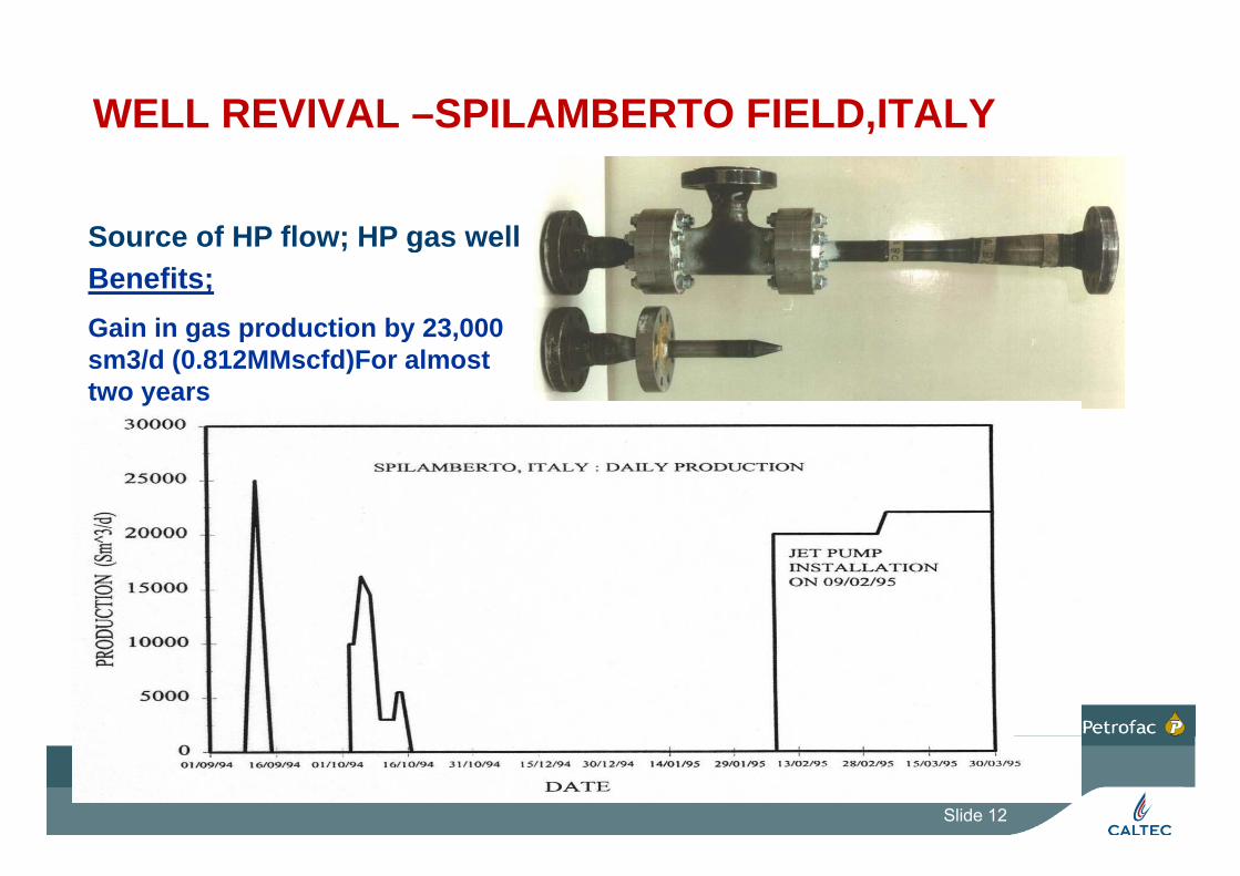
WELL REVIVAL –SPILAMBERTO FIELD,ITALY
Source of HP flow; HP gas wellSource of HP flow; HP gas wellBenefits;Gain in gas production by 23,000 g p y ,sm3/d (0.812MMscfd)For almost two years
Slide 12
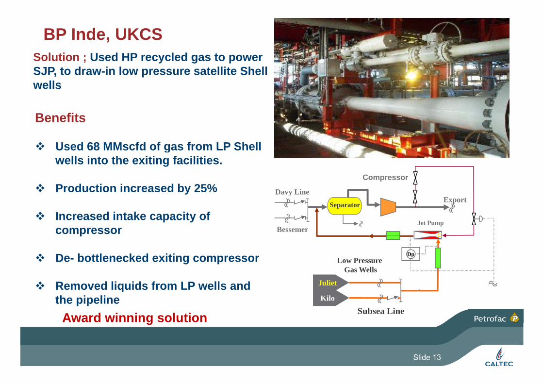
BP Inde, UKCSSolution ; Used HP recycled gas to power ; y g pSJP, to draw-in low pressure satellite Shell wells
Benefits
Used 68 MMscfd of gas from LP Shell Used 68 MMscfd of gas from LP Shell wells into the exiting facilities.
Production increased by 25% Davy Line
Compressor Production increased by 25%
Increased intake capacity of compressor
Jet Pump
ExportDavy Line
Bessemer
Separator
p
De- bottlenecked exiting compressor Low Pressure Gas Wells
Dp
Removed liquids from LP wells and the pipeline Kilo
Juliet
Subsea LineAward winning solutiong
Slide 13
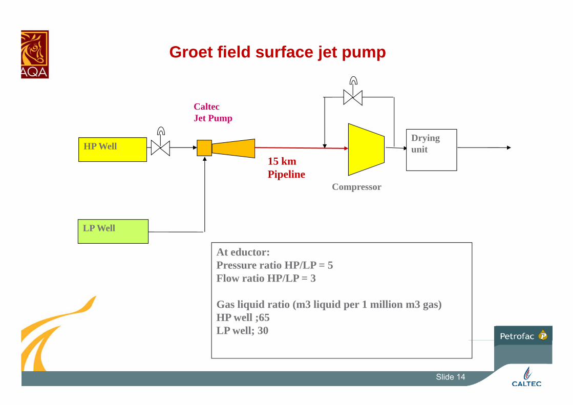
Groet field surface jet pump
Caltec
HP WellDryingunit
Jet Pump
15 km Pipeline
Compressor
LP Well
A dAt eductor:Pressure ratio HP/LP = 5Flow ratio HP/LP = 3
Gas liquid ratio (m3 liquid per 1 million m3 gas)HP well ;65LP well; 30
Slide 14
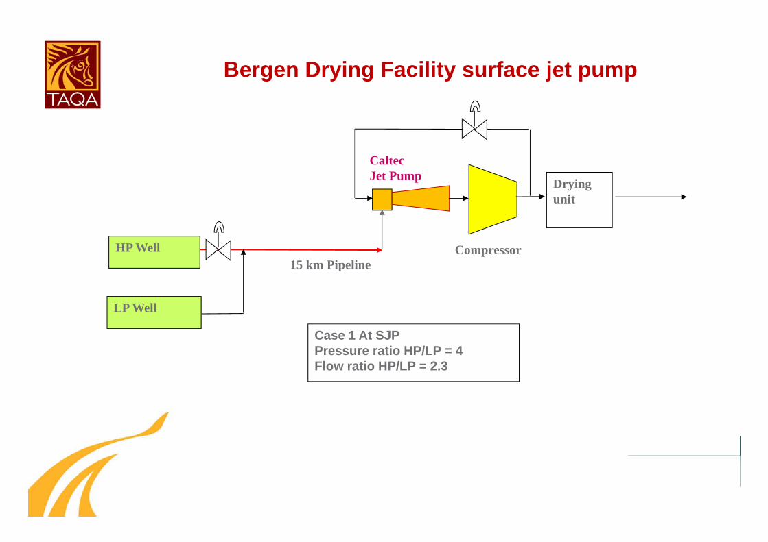
Bergen Drying Facility surface jet pump
Dryingunit
CaltecJet Pump
HP Well15 km Pipeline
Compressor
LP Well
p
C 1 At SJPCase 1 At SJPPressure ratio HP/LP = 4Flow ratio HP/LP = 2.3
Slide 15

Slide 16
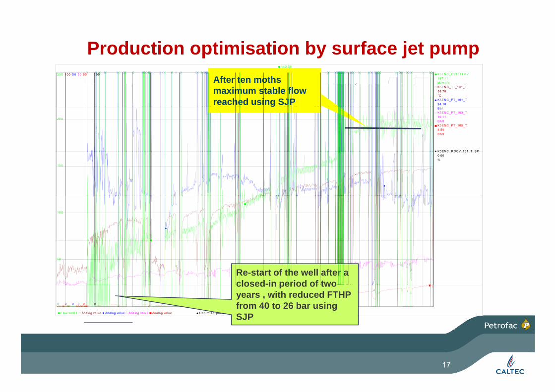
Production optimisation by surface jet pumpK5ENC_QV101T.PV
kNm 3/dK5ENC_TT_101_T
°CK5ENC_PT_101_T
K5ENC T = well 1 26/05/2008 09:49:03.893
250 100 5 0 50 50 50 100
24.18
58.78
197.11
142.3950.8625.818.261.442.7594.99
After ten moths maximum stable flow reached using SJP
BarK5ENC_PT_103_T
BARK5ENC_PT_105_T
BARK5ENC_PT_107_T
BARK5ENC ROCV 101 T SP
200
11.87
4.54
10.11
K5ENC_ROCV_101_T_SP
%
150
0.00
100
50
Re-start of the well after a closed-in period of two
F low wel l T Analog value Analog value Ana log valu e Analog value Analog value Return s et pointd ays-336 -308 -280 -252 -224 -196 -168 -140 -11 2 -84 -56 -28
0 0 0 0 0 0 014/01 /20 08 1 6:4 7:42.74 54 6
closed in period of two years , with reduced FTHP from 40 to 26 bar using SJP
17

Chevron, USA (GOM)Solution ; HP gas from the existing compressor on recycle used to power the jet pump
BenefitsL d i l t th l tf b 200 i Lowered arrival p at the platform by 200 psi
Increased gas velocity and improved flow regime in wellsin wells
• Removed bulk of liquids in the pipeline, causing a further 140psi drop at the wellhead
(340 psi total pressure drop).
• Production increased by 24%.
Export40MMSCFD400 psig
200 psig
1250 i
Salesprocessy %
• 2.5 Bscf of otherwise lost reserves recovered.
Fl d li d t hi h t
Ejector 1250 psig
Recycle gas
•Flow delivered at higher pressure to compressor suction increased compressor throughput.
7.4 MMSCFD850 psig Subsea
manifold
GEMINI
(Php/Plp=4.9.Qhp/Qlp= 2.11,Pd/Plp=2 ) 27 miles
Slide 18
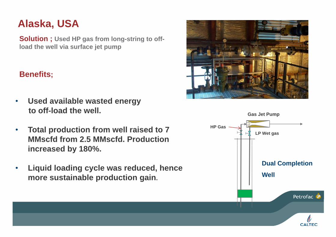
Alaska, USASolution ; Used HP gas from long string to offSolution ; Used HP gas from long-string to off-load the well via surface jet pump
Benefits;
• Used available wasted energy to off-load the well. Gas Jet Pump
• Total production from well raised to 7 MMscfd from 2.5 MMscfd. Production
LP Wet gasHP Gas
increased by 180%.
• Liquid loading cycle was reduced, hence Dual Completion
more sustainable production gain. Well

WELLCOM APPLICATION: Cendor, Malaysia
WELLCOM BOOSTING SYSTEM
Wellcom oil system ; multiphase HP wells were used to bring in closed low pressure oil wells.
I-SEP
Benefits
Used available energy from HP well
TO PROCESS SYSTEM
JET PUMPFROM HP WELL
GAS• Used available energy from HP well
• 20% pressure boost for LP wells. FTHP 360 psia
I-SEPSYSTEM
COMMINGLER
LIQUID• Increased production by over 35%
( 150 b/d ) FTHP 69.6 PSIA87 psia
3612 b/d
Dp FWHP; 17 4 psi
FROM LP WELL• Improved flow regime in well bore, stabilising production.
450 b/d+0.138 MMSCFD
Dp FWHP; 17.4 psi
Slide 20
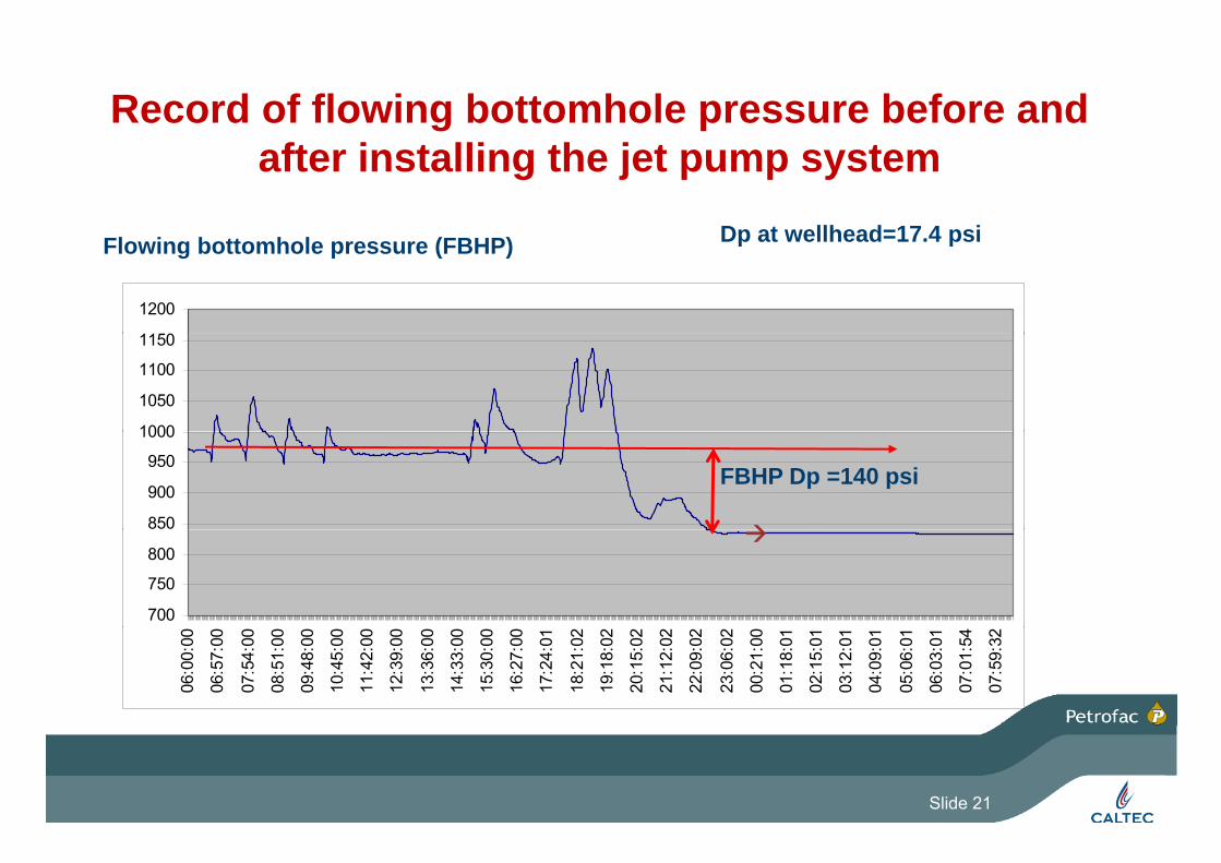
Record of flowing bottomhole pressure before and after installing the jet pump system
Dp at wellhead=17 4 psi
1150
1200
Flowing bottomhole pressure (FBHP) Dp at wellhead=17.4 psi
1000
1050
1100
1150
850
900
950
1000
FBHP Dp =140 psi
700
750
800
06:0
0:00
06:5
7:00
07:5
4:00
08:5
1:00
09:4
8:00
10:4
5:00
11:4
2:00
12:3
9:00
13:3
6:00
14:3
3:00
15:3
0:00
16:2
7:00
17:2
4:01
18:2
1:02
19:1
8:02
20:1
5:02
21:1
2:02
22:0
9:02
23:0
6:02
00:2
1:00
01:1
8:01
02:1
5:01
03:1
2:01
04:0
9:01
05:0
6:01
06:0
3:01
07:0
1:54
07:5
9:32
Slide 21
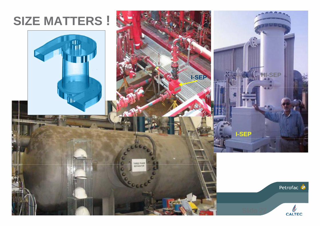
SIZE MATTERS !
HI-SEPI-SEP
I-SEP
Slide 22

EFFECT OF SJP COMBINED WITH GAS LIFTINCREASED PRODUCTIONINCREASED PRODUCTION
Gaslift injectionWellhead
SJP
HPGaslift injection
system
Wellcom system &
Well production
Surface
w ra
te Additional
production
To downstream process
Production
via TubingGaslift injection
d O
il Fl
ow
Well
Prod
uce
Gaslift Injection Flowrate
Gaslift injection
Lift gas Gaslift Injection Flowrate
Pay zone Pay zone
Wellbore
Slide 23
Wellbore
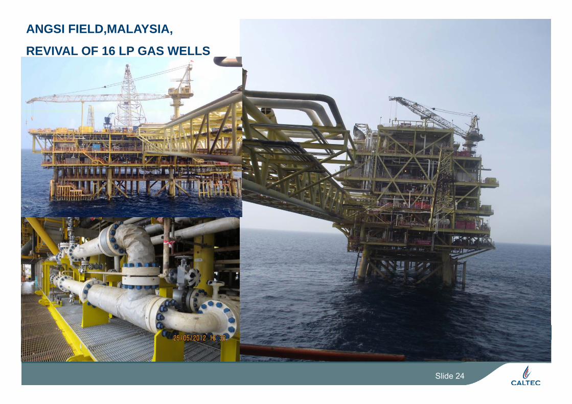
ANGSI FIELD,MALAYSIA,
REVIVAL OF 16 LP GAS WELLS
Slide 24

ANGSI FIELD,MALAYSIA

ANGSI FIELD,USE OF TEST SEPARATOR TO MEASURE FLOW RATE OF GAS AND LIQUIDS AT LOWER FWHPS

- -
WELL REVIVAL AND FLOW RATE MEASUREMENTUSING
THE TEST SEPARATOR
Well Revival
THE TEST SEPARATORAPPLIES TO BOTH GAS AND OIL WELLS
Well Revival Gas Jet Pump
Well Revival
HP Gas
To vent or Well Revival
Liquid Jet PUMP
HP Liquid
To vent or flare ,option3)
(Option 2)
LP Wells
Test Header
M
Gas
Closed drain
Production Header
Test SeparatorM Liquid
Closed drain
(option 1)
c.
10 October, 2013Presentation title 27

To Pressure Relief Line
Gas Jet PumpDischarge Silencer
Production Cooler 14” Sub Sea
PTPT
TTPT PT
Silen
cers
Sk
id
HP Well
CoolerLine to CPP
LP Silencer
Di h
Jet Pump Skid
PTAlternative
use of booster pump
PT
Well Revival Jet Pump
PT
Discharge Silencer
cers
d
Test Header Commingler
TTPT
LP SilencerJet Pump Skid
Silen
cSk
i
Test Separator
MLP Wells
Test Cooler
gLP Silencer
M
MProduction Header
USE OF TEST SEPARATOR TO REVIVE LOADED WELLSUSE OF TEST SEPARATOR TO REVIVE LOADED WELLS
Slide 28

TYPICAL NOZZLE PERFORMANCE CURVE
10 October, 2013
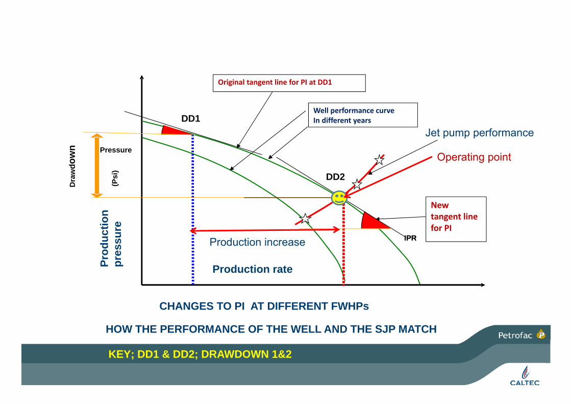
Well performance curve
Original tangent line for PI at DD1
DD1
wn Pressure
Well performance curveIn different years
Jet pump performance
Operating point
Dra
wdo
w
DD2
(Psi
)
N
Operating point
IPRIPR
New tangent line for PI
duct
ion
ssur
e
Production increase
Production rateProd
pres
CHANGES TO PI AT DIFFERENT FWHPs
HOW THE PERFORMANCE OF THE WELL AND THE SJP MATCH
KEY; DD1 & DD2; DRAWDOWN 1&2
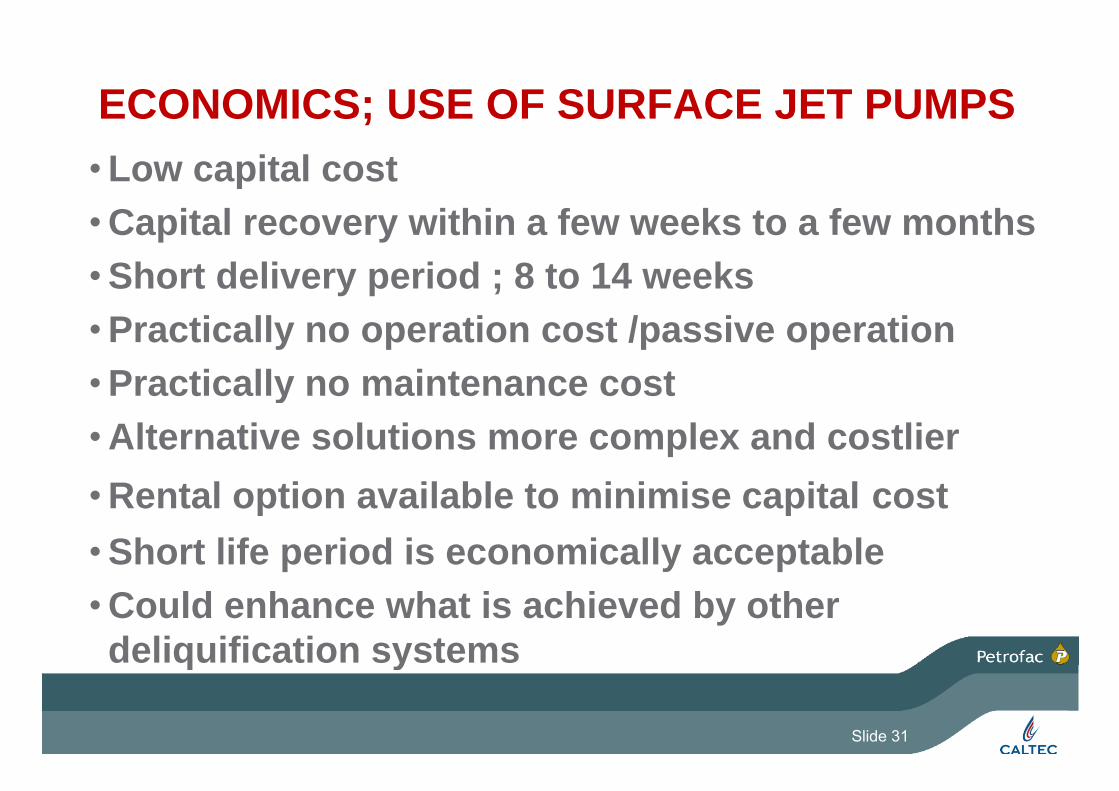
ECONOMICS; USE OF SURFACE JET PUMPS• Low capital costCapital recovery within a few weeks to a few months• Capital recovery within a few weeks to a few months
• Short delivery period ; 8 to 14 weeks• Practically no operation cost /passive operation• Practically no maintenance costPractically no maintenance cost• Alternative solutions more complex and costlierR t l ti il bl t i i i it l t• Rental option available to minimise capital cost
• Short life period is economically acceptable• Could enhance what is achieved by other deliquification systems q y
Slide 31

CLOSING REMARKS• Simplicity & cost effectiveness makes surface jet pump
solutions very attractive & economicaly• A good tool for initial well deliquification before the situation
worsens• In addition to economic benefits, eliminating intermediate
compressors, deferring compressor upgrading or reducing li id h ld i i li ddi i l b filiquid hold up in pipelines are additional benefits
• The system can work well with other deliquification l tisolutions
• Installing tie-in points during shut downs simplifies installationinstallation
• Rental option justifies very short operation life
Slide 32

THANK YOUTHANK YOUQUESTIONS WELLCOMEQUESTIONS WELLCOME
Slide 33