
DelhiProductsCatalogue Jan2011 BvilleMfgProds & EMUA Series . . . . . . . . . . . . . . . . . . . ....
40
Transcript of DelhiProductsCatalogue Jan2011 BvilleMfgProds & EMUA Series . . . . . . . . . . . . . . . . . . . ....

CONTENTS
SINGLE & TWIN FORWARD CURVED INLINEDUCT BLOWERS200 Series . . . . . . . . . . . . . . . . . . . . . . . . . . . . . .1-29200 Series . . . . . . . . . . . . . . . . . . . . . . . . . . . . .1-29200-VIB Series . . . . . . . . . . . . . . . . . . . . . . . . .1-2
FILTER SECTIONS & INTAKE HOODS F200A Filter Section . . . . . . . . . . . . . . . . . . . . . . . .2F9220A Filter Section . . . . . . . . . . . . . . . . . . . . . . .2H9200 Intake Hood . . . . . . . . . . . . . . . . . . . . . . . .2
FORWARD CURVED INLINE SERIES DUCT BLOWERSGreen Series 200DD . . . . . . . . . . . . . . . . . . . . . .3-4Green Series 9200DD . . . . . . . . . . . . . . . . . . . . .3-4
FILTER SECTIONS & INTAKE HOODS F200A Filter Section . . . . . . . . . . . . . . . . . . . . . . . .4H9200 Intake Hood . . . . . . . . . . . . . . . . . . . . . . . .4
PERFORMANCE GREEN DIRECT DRIVE SERIESEnergy Efficient Direct Drive Cabinet Blowers . . . .5
HEATING & COOLING COILSHC Series Hot Water Heating Coils . . . . . . . . . . . . . .6CW Series Cooled Water Coils . . . . . . . . . . . . . . .6
FC EXHAUSTER BELT DRIVE UTILITY BLOWERS400 Series . . . . . . . . . . . . . . . . . . . . . . . . . . . . . . . . . .7600 Series . . . . . . . . . . . . . . . . . . . . . . . . . . . . . . .8
BACKWARD INCLINED BELT DRIVE SQUARE INLINE BLOWERSDSQ-B Series . . . . . . . . . . . . . . . . . . . . . . . . . . . . .9
BACKWARD INCLINED DIRECT DRIVE SQUARE INLINE BLOWERSDSQ-D Series . . . . . . . . . . . . . . . . . . . . . . . . . . . .10
FORWARD CURVED ROOF EXHAUSTERS300 Series . . . . . . . . . . . . . . . . . . . . . . . . . . . . . .11Green Series 300DD . . . . . . . . . . . . . . . . . . . . . . .12
FILTERED FRESH AIR SUPPLY UNITS700 Series . . . . . . . . . . . . . . . . . . . . . . . . . . . . . .13Green Series 700DD . . . . . . . . . . . . . . . . . . . . . . .14
SIDE INTAKE FILTERED FRESH AIR SUPPLYUNITSSIS Series . . . . . . . . . . . . . . . . . . . . . . . . . . . . . . .15Green Series SISDD . . . . . . . . . . . . . . . . . . . . . . .16
BELT DRIVE UTILITY BLOWERSBI Series . . . . . . . . . . . . . . . . . . . . . . . . . . . . .17-18BI-RM Series . . . . . . . . . . . . . . . . . . . . . . . . . .17-18
OPTIONS & ACCESSORIESBack Draft Dampers . . . . . . . . . . . . . . . . . . . . . . .19Inlet Screens . . . . . . . . . . . . . . . . . . . . . . . . . . . . .19Outlet Screens . . . . . . . . . . . . . . . . . . . . . . . . . . .19Bolted Clean Out Door . . . . . . . . . . . . . . . . . . . . .19Heat Slinger . . . . . . . . . . . . . . . . . . . . . . . . . . . . .19V Cap . . . . . . . . . . . . . . . . . . . . . . . . . . . . . . . . . .19Drain Fitting . . . . . . . . . . . . . . . . . . . . . . . . . . . . .19Shaft Seal . . . . . . . . . . . . . . . . . . . . . . . . . . . . . . .19Vibration Isolators Rubber . . . . . . . . . . . . . . . . . .19Vibration Isolators Spring . . . . . . . . . . . . . . . . . . .19Vibration Isolators Outdoor Spring . . . . . . . . . . . .19Aluminum Wheel . . . . . . . . . . . . . . . . . . . . . . . . .19
CENTRIFUGAL, FORWARD CURVED, DIRECT DRIVE DWDI BLOWERSG-DD Series . . . . . . . . . . . . . . . . . . . . . . . . . . . . .20
DOUBLE INLET BELT DRIVE BLOWERSG Series . . . . . . . . . . . . . . . . . . . . . . . . . . . . . . . .21
DOUBLE WIDTH, DOUBLE INLET BLOWERS WITH FRAME800 Series . . . . . . . . . . . . . . . . . . . . . . . . . . . . . .22
DOUBLE WIDTH, DOUBLE INLET, FRAMED HEAVY DUTY BLOWERS - WITH PILLOW BLOCK BEARINGS900 Series . . . . . . . . . . . . . . . . . . . . . . . . . . . . . .23
DOUBLE WIDTH, DOUBLE INLET BACKWARDINCLINED BLOWERSBIDI Series . . . . . . . . . . . . . . . . . . . . . . . . . . . . . .24
PLENUM FANSDPL Series . . . . . . . . . . . . . . . . . . . . . . . . . . . . . .25DPL-AF Series . . . . . . . . . . . . . . . . . . . . . . . . . . .25
DIRECT DRIVE UTILITY BLOWERSD500 Series . . . . . . . . . . . . . . . . . . . . . . . . . . . . .26
DIRECT DRIVE PRESSURE BLOWERSPW Series . . . . . . . . . . . . . . . . . . . . . . . . . . . . . . .27
DIRECT DRIVE RADIAL BLADE BLOWERSKE Series . . . . . . . . . . . . . . . . . . . . . . . . . . . . . . .28
DIRECT DRIVE FORWARD CURVED BLOWERSD Series . . . . . . . . . . . . . . . . . . . . . . . . . . . . . . . .29
BELT DRIVE UPBLAST SPUN ALUMINUM EXHAUSTERSSBRM Series . . . . . . . . . . . . . . . . . . . . . . . . . . . .30
DIRECT DRIVE UPBLAST SPUN ALUMINUM EXHAUSTERSSDUB Series . . . . . . . . . . . . . . . . . . . . . . . . . . . . .31
BELT DRIVE DOWNBLAST SPUN ALUMINUM EXHAUSTERSSB Series . . . . . . . . . . . . . . . . . . . . . . . . . . . . . . .32
DIRECT DRIVE DOWNBLAST SPUN ALUMINUM EXHAUSTERSSD Series . . . . . . . . . . . . . . . . . . . . . . . . . . . . . . .33
ECONOMY MAKE UP AIR UNITSSDS & EMUA Series . . . . . . . . . . . . . . . . . . . . . . .34
VARIABLE FREQUENCY DRIVES & SPEED CONTROLSB, EL & MC Series . . . . . . . . . . . . . . . . . . . . . . . .35
CONTACTS . . . . . . . . . . . . . . . . . . . . . . . . . . . . . . .36OTHER CANARM PRODUCTS . . . . . . . . . . . . .37

Subject to change without notice. 01/11 Page 1
200, 9200 & 9200-VIB SERIESSINGLE & TWIN FORWARD CURVED INLINE DUCT BLOWERS
• Wheel Diameters: 7” through 20”• CFM: Approximately 500 to 12,500 CFM in a single blower (Twins available).• Static Pressure: Usage to about 3” static pressure is common, although allowable range is higher.• Constructed from cold rolled steel, with green baked on powder coat. The outdoor unit uses
protective galvaneal steel under the powder coat.• Forward Curved blowers operate at low RPM for low noise levels.• Heavy duty ball bearings suitable for -65º F to +250º F.• Keywayed shafts both ends for clockwise or counter clockwise rotation.• Saddle type motor mounting platform provides extended belt tension adjustment range on all models.
Twin Units (not illustrated) use a common shaft for balanced air supply by each blower.
TYPICAL APPLICATIONS FOR OUR INLINE BLOWERS• An Inline make-up air solution for cases where a rooftop curb mounted solution is not available.• As an air moving module for systems built up with other components such as heating/cooling coils.• Noise sensitive areas - the low rpm forward curved wheel typically radiates less vibration than higher rpm backward inclined wheel solutions.• When the application requires an air mover in a duct system located in a ceiling space.• Redistribution or recirculation of air in a work space.• Interlocked with entry doors to prevent entry of cold outdoor air into retail sales space and thus greets customers with warmth.• Bathroom/ rest room exhaust - one duct blower serving multiple intakes.
FEATURES
• As part of an HVAC system Delhi Duct Blowers will not “surge”, “hunt”, or “stall”.• The variable pitch motor pulley permits field adjustment (typically + or - 15%) to match air delivery needs.• For the quietest operational needs we offer optional internal spring isolation of the blower/motor from the housing thus greatly reducing radiated cabinet noise.
• Our twins (two duct blowers on a common shaft) is a wide but not tall solution for situations where vertical space is limited.
• Quiet forward curved blowers operate at ½ the rpm of other inline solutions.• An outdoor series, 9200, is available.
GENERAL INFORMATIONCanarm certifies that the 200& 9200 Series shown herein
are licensed to bear theAMCA Seal.
The ratings shown are basedon tests and procedures
performed in accordancewith AMCA Publications
211 & 311 and comply withthe requirements of theAMCA Certified Ratings
Programme.
INDUSTRIES SERVED• Commercial HVAC• Ventilation• Heating• Cooling• Construction
200 SERIES Indoor Applications, Insulated or Non-Insulated
9200 SERIES Heavy duty, Insulated Indoor or Outdoor Applications
9200-VIB SERIESWith Internal Spring Vibration Isolation
MODEL 1/2” SP 1” SP 1 1/2” SP 2" SP 2 1/2" SP Max HP207 1400 1250 1100 900 700 3/4209 1800 1600 1400 1100 800 3/49209 2400 2300 2100 1900 1700 1 1/2210 2100 1800 1400 1000 700 1 1/29210 2900 2700 2500 2100 1700 1 1/2212 3600 3200 2800 2300 1800 1 1/29212 4300 4300 4100 3800 3500 3215 5700 5200 4600 4000 3400 39215 6200 6200 6200 5700 5200 5218 & 9218 9000 8250 7500 6700 5750 59220 13000 13000 13000 13000 13000 15
TYPICAL MAXIMUM CFM @ SP
CFM values listed right are summarized for convenience.For full performance data refer to our Delair program.
Power rating (BHP) does not include transmission losses.Performance certified is for installation type B: Free inlet,Ducted outlet. Performance ratings do not include theeffect of appurtenances (accessories).
PERFORMANCE SPECIFICATIONS
705

Subject to change without notice. 01/11Page 2
D E L M207 18" 15.375" 23" 8 1/4" 9 3/16" 14 1/2" 9 5/8" 1 1/4" 1 1/4" 7/8" 15 7/8" 13 3/8" 3/4" 43
209 21" 18" 23" 10 1/4" 11 13/16" 17 1/2" 11 3/4" 1 1/4" 1 3/4" 7/8" 19" 16" 3/4" 55
210 22.25" 20" 24 3/4" 11 3/8" 13 1/8" 18 3/4" 13 3/8" 1 1/4" 1 3/4" 7/8" 20 1/4" 18" 3/4" 65
212 27" 23" 27 1/2" 13 7/16" 15 5/8" 23 1/2" 16 1/8" 1 1/4" 1 3/4" 7/8" 25" 21" 3/4" 82
215 33.5" 28" 32" 15 7/8" 18 5/8" 28" 19 1/2" 2 5/8" 1 3/4" 7/8" 30 1/2" 25" 1" 140
218 41.5" 34" 44" 19 5/8" 22 5/8" 35" 24" 2 3/4" 1 3/4" 1 1/8" 35 3/8" 31 5/8" 1" 158
9209 21" 18" 23" 11 1/4" 12 3/4" N/A N/A 1" N/A 1 1/8" 19" 16" 3/4" 61
9210 22 1/4" 20" 24 3/4" 12 3/8" 14 1/8" N/A N/A 1" N/A 1 1/8" 20 1/4" 18" 3/4" 70
9212 30 1/8" 24 3/4" 34" 14 1/2" 16 5/8" N/A N/A 2 1/8" N/A 1 1/8" 25 1/8" 21 1/8" 1" 143
9215 33 3/4" 28 5/8" 38 1/8" 17" 19 5/8" N/A N/A 2 1/8" N/A 1 1/8" 30 5/8" 25 1/4" 1" 176
9218 41 1/2" 34" 44" 19 5/8" 22 5/8" N/A N/A 2 3/4" N/A 1 1/8" 35 3/8" 31 5/8" 1" 323
9220 44 3/4" 41 1/8" 57 1/2" 25 3/4" 25 3/4" N/A N/A 3" N/A 1 1/8" 38 3/8" 35 1/8" 1 7/16" 515
MODELINLET
F G H J
OUTLET
A B C K
SHAFT DIAMETER
UNIT WEIGHT(LBS)
(without motor)
GJ
F
L
M
CA
K
E
DH
B M
1”
C
HB D
E
KA
L
DIMENSIONSDIMENSIONS
OPTIONSOPTIONS
200, 9200 & 9200-VIB SERIESSINGLE & TWIN FORWARD CURVED INLINE DUCT BLOWERS
OPTIONSOPTIONS
ACCESSORIESACCESSORIES• Filter sections• Intake Hoods• External Vibration Isolators
• Hot Water Coils• Chilled Water Coils
FILTER SECTIONS & INTAKE HOODSSERIES F200A, F9220A & H9200
F200A FILTER SECTIONFor 200 & 9200 Series Duct Blowers
F9220A FILTER SECTIONFor Model 9220 Duct Blowers
H9200 INTAKE HOODFor 9200 Series Duct Blowers
SIZE QUANTITY
F207A 17 3/4" 15 3/8" 16" 13 1/2" 14 1/8" X 16 5/8" 1 11
F209A 21" 18" 19 1/8" 16 1/8" 16 3/4" X 19 7/8" 1 12
F210A 22 1/4" 20" 20 3/8" 18 1/8" 18 3/4" X 21 1/8" 1 14
F212A 27" 23" 25 1/8" 21 1/8" 21 3/4" X 25 7/8" 1 16
F215A 32 1/2" 26 3/4" 30 5/8" 25 1/8" 25 3/4" X 31" 1 21
F218A 37" 33 1/4" 35 1/4" 31 1/2" 32 1/4" X 35 7/8" 1 46
F9220A 39 3/4" 37 1/4" 38 1/2" 35 1/4" 20" X 25" 6 64
FILTERAMODEL B PN
UNIT WEIGHT (LBS) SIZE QUANTITY
H9209 19 1/4" 16 9/16" 21 1/4" 16" X 24" 1 14
H9210 20 1/2" 18 9/16" 25 3/4" 15" X 20" 2 16
H9212 25 3/8" 21 9/16" 30 3/4" 20" X 25 & 16" X 25" 2 27
H9215 31 3/16" 25 13/16" 33 1/2" 20" X 28 1/2" 2 38
H9218 35 5/8" 32 11/16" 40 1/4" 20" X 25 (2) & 16" X 25" 3 50
40H9220 38 5/8" 35 9/16" 22"FILTERS NOT INCLUDED
USE F9220A
UNIT WEIGHT (LBS)
FILTERMODEL L M Z
N
P
2"
1"
B
A
P
N
1"
N
P
22-1/2"
1"N
A
BP
M
LZ

Page 3
GREEN SERIES 200DD & 9200DDFORWARD CURVED INLINE SERIES DUCT BLOWERS
• High efficiency direct drive motor for energy efficient, low maintenance applications.• Forward curved blowers operate at low RPM for low noise levels.• Attractive green baked on powder coat finish.
FEATURES
0"SP 0.25" 0.5" 0.75"CFM700 1/2-L800 1/2-L
900 1/2-L
1000 3/4-L1100 3/4-L
1200 3/4-L 1-L 1/2-ML1300 1-L 1/2-ML 1/2-M 1400 1-L 1/2-ML 1/2-M 1/2-MH1500 1/2-ML 1/2-M 1/2-MH 1/2-H1600 1/2-M 1/2-MH 1/2-H 3/4-ML1700 1/2-MH 1/2-H 3/4-ML 3/4-M/1-M1800 1/2-H 3/4-ML 3/4-M 3/4-MH/1-ML1900 3/4-ML 3/4-M 3/4-MH/1-ML 3/4-H/1-H2000 3/4-M 3/4-MH/1-ML 3/4-H2100 3/4-MH/1-ML 3/4-H 1-MH/1-M2200 3/4-H 1-M 1-H2300 1-M 1-MH
2400 1-MH 1-H
2500 1-H
2600
GREEN SERIES DATA 209DD 9209DD0"SP 0.25" 0.5" 0.75" 1" 1.25"
CFM700 1/2-L 3/4-L800 1/2-L 3/4-L900 1/2-L 1-L1000 3/4-L1100 3/4-L
1200 3/4-L 1-L 1/2-ML 1/2-ML 1/2-ML1300 1-L 1/2-ML 1/2-M 1/2-M 1/2-M 1400 1-L 1/2-ML 1/2-M 1/2-MH 1/2-MH 1/2-MH1500 1/2-ML 1/2-M 1/2-MH 1/2-H 1/2-H 1/2-H1600 1/2-M 1/2-MH 1/2-H 3/4-ML 3/4-ML 3/4-ML1700 1/2-MH 1/2-H 3/4-ML 3/4-M/1-M 3/4-M/1-M 3/4-M/1-M1800 1/2-H 3/4-ML 3/4-M 3/4-MH/1-MH 3/4-MH/1-MH 3/4-MH/1-MH1900 3/4-ML 3/4-M 3/4-MH/1-ML 3/4-H/1-H 3/4-H/1-H 3/4-H/1-H2000 3/4-M 3/4-MH/1-ML 3/4-H2100 3/4-MH/1-ML 3/4-H 1-MH/1-M2200 3/4-H 1-M 1-H2300 1-M 1-MH
2400 1-MH 1-H
2500 1-H
2600
GREEN SERIES DATA 210DD 9210DD
0"SP 0.25" 0.5" 0.75" 1" 1.25" 1.5" 1.75"
CFM
500 1/2-L 3/4-L 1-L800 1/2-L 3/4-L 1-L 1/2-ML1000 1/2-L 1/2-M 1100 3/4-L 1-L 1/2-ML1200 1/2-MH1300 3/4-L 1-L 1/2-M 1400 1/2-ML 1/2-MH 1/2-H 1-ML1500 1/2-ML 1/2-M 1600 1/2-ML/1-L 1/2-M 1/2-MH 1/2-H 3/4 ML 3/4-M/1-ML1700 1/2-M 1/2-MH 1/2-H 3/4-ML 3/4-M 3/4-MH 3/4-H/1-M 1-MH1800 1/2-MH 1/2-H 3/4-ML 3/4-M 3/4-MH/1-ML 3/4-H/1-M1900 1/2-H 3/4-ML 3/4-M 3/4-MH 3/4-H 1-MH 1-H2000 3/4-ML 3/4-M 3/4-MH 3/4-H/1-ML 1-M 1-MH 1-H2100 3/4-M 3/4-ML 3/4-H/1-ML 1-ML2200 3/4-MH 3/4-H 1-M 1-H2300 3/4-H 1-ML 1-M 1-MH 1-H2400 1-ML 1-MH2500 1-M 1-H2600 1-M 1-MH 1-H2700 1-MH 1-H
2800 1-H
2900
GREEN SERIES DATA 212DD 9212DDChart cells reference Motor HP and Motor Speedfor performance (motor to be wired accordingly).H - High MH - Medium High M - MediumML - Medium LowL - Low
Performance tested in accordance to AMCA STD210-85.
Operating at Static Pressure ratings above listeddata is not recommended.
Performance drops off drastically and surgingmay occur.
Performance limited to green highlighted areasof the charts. Do not select yellow areas.
Motor HPʼs of 1/2, 3/4 and 1 are available in 115Volt and 230 Volt in Single Phase ONLY.
PERFORMANCE SPECIFICATIONS
200DD SERIES Indoor Applications, Insulated or Non-Insulated
9200DD SERIES Heavy duty, Insulated Indoor or Outdoor Applications
Subject to change without notice. 01/11

Page 4
D E L M
209DD 21" 18" 23" 10 1/4" 11 13/16" 17 1/2" 11 3/4" 1 1/4" 1 3/4" 7/8" 19" 16" 3/4" 55
210DD 22.25" 20" 24 3/4" 11 3/8" 13 1/8" 18 3/4" 13 3/8" 1 1/4" 1 3/4" 7/8" 20 1/4" 18" 3/4" 65
212DD 27" 23" 27 1/2" 13 7/16" 15 5/8" 23 1/2" 16 1/8" 1 1/4" 1 3/4" 7/8" 25" 21" 3/4" 82
9209DD 21" 18" 23" 11 1/4" 12 3/4" N/A N/A 1" N/A 1 1/8" 19" 16" 3/4" 61
9210DD 22 1/4" 20" 24 3/4" 12 3/8" 14 1/8" N/A N/A 1" N/A 1 1/8" 20 1/4" 18" 3/4" 70
9212DD 30 1/8" 24 3/4" 34" 14 1/2" 16 5/8" N/A N/A 2 1/8" N/A 1 1/8" 25 1/8" 21 1/8" 1" 143
C KSHAFT
DIAMETER
UNIT WEIGHT(LBS)
(without motor)MODEL
INLET
F G H J
OUTLET
A B
GJ
F
L
M
CA
K
E
DH
BM
1”
C
HB D
E
KA
L
DIMENSIONSDIMENSIONS
OPTIONSOPTIONS
GREEN SERIES 200DD & 9200DDFORWARD CURVED INLINE SERIES DUCT BLOWERS
FILTER SECTIONS & INTAKE HOODSSERIES F200A, F9220A & H9200
F200A FILTER SECTIONFor 200DD & 9200DD Series Duct Blowers
H9200 INTAKE HOODFor 9200DD Series Duct Blowers
SIZE QUANTITY
F209A 21" 18" 19 1/8" 16 1/8" 16 3/4" X 19 7/8" 1 12
F210A 22 1/4" 20" 20 3/8" 18 1/8" 18 3/4" X 21 1/8" 1 14
F212A 27" 23" 25 1/8" 21 1/8" 21 3/4" X 25 7/8" 1 16
FILTERMODEL A B N P
UNIT WEIGHT (LBS)
SIZE QUANTITY
H9209 19 1/4" 16 9/16" 21 1/4" 16" X 24" 1 14
H9210 20 1/2" 18 9/16" 25 3/4" 15" X 20" 2 16
H9212 25 3/8" 21 9/16" 30 3/4" 20" X 25 & 16" X 25" 2 27
M ZUNIT WEIGHT
(LBS)
FILTERMODEL L
N
P
2"
1"
B
A
P
N
1"
M
LZ
OPTIONSOPTIONS
ACCESSORIESACCESSORIES • Filter sections• Intake Hoods
• Vibration Isolators• Back Draft Dampers
Subject to change without notice. 01/11
Page 5
PERFORMANCE GREENDIRECT DRIVE SERIESENERGY EFFICIENT DIRECT DRIVE CABINET BLOWERS
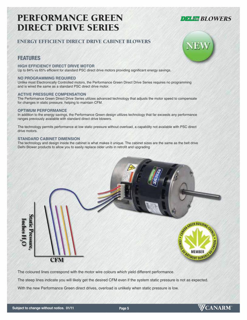
HIGH EFFICIENCY DIRECT DRIVE MOTORUp to 84% vs 65% efficient for standard PSC direct drive motors providing significant energy savings.
NO PROGRAMMING REQUIREDUnlike most Electronically Controlled motors, the Performance Green Direct Drive Series requires no programming and is wired the same as a standard PSC direct drive motor.
ACTIVE PRESSURE COMPENSATIONThe Performance Green Direct Drive Series utilizes advanced technology that adjusts the motor speed to compensate for changes in static pressure, helping to maintain CFM.
OPTIMUM PERFORMANCEIn addition to the energy savings, the Performance Green design utilizes technology that far exceeds any performance ranges previously available with standard direct drive blowers.
The technology permits performance at low static pressure without overload, a capability not available with PSC direct drive motors.
STANDARD CABINET DIMENSIONThe technology and design inside the cabinet is what makes it unique. The cabinet sizes are the same as the belt drive Delhi Blower products to allow you to easily replace older units in retrofit and upgrading
FEATURES
The coloured lines correspond with the motor wire colours which yield different performance.
The steep lines indicate you will likely get the desired CFM even if the system static pressure is not as expected.
With the new Performance Green direct drives, overload is unlikely when static pressure is low.
Subject to change without notice. 01/11

Subject to change without notice. 01/11Page 6
HC & CW SERIESHEATING & COOLING COILS
HC SERIES Hot Water Heating Coils
B P
AN
2-1/4"1"
AN
B P
6"1"
MODELA
(HC)A
(CW & DX)B N P INLET OUTLET
UNIT WEIGHT(LBS)
INLET OUTLETUNIT WEIGHT
(LBS)
HC-07 & CW-07 17 3/4" 17 3/4" 15 3/8" 16" 13 1/2" 5/8" 5/8" 10 5/8" 5/8" 22
HC-09 & CW-09 21" 21" 18" 19 1/8" 16 1/8" 5/8" 5/8" 14 7/8" 7/8" 29
HC-10 & CW-10 22 1/4" 22 1/4" 20" 20 3/8" 18 1/8" 5/8" 5/8" 17 7/8" 7/8" 36
HC-12 & CW-12 27" 27" 23" 25 1/8" 21 1/8" 3/4" 3/4" 23 7/8" 7/8" 42
HC-15 & CW-15 32 1/2" 33 1/2" 26 3/4" 30 5/8" 25 1/8" 3/4" 3/4" 32 7/8" 7/8" 61
HC-CW COILS HC COILS CW COILS
DRAIN IS 5/8" IN -OD
DUCT BLOWER HEATING COIL CHILLED WATER COIL FILTER INTAKE HOOD
207 HC-07 CW-07 F207A N/A
209 OR 9209 HC-09 CW-09 F209A H9209
210 OR 9210 HC-10 CW-10 F210A H9210
212 OR 9212 HC-12 CW-12 F212A H9212
215 OR 9215 HC-15 CW-15 F215A H9215
MATCHING COIL SECTIONS
DIMENSIONSDIMENSIONS
OPTIONSOPTIONS
2 Row CoilHorizontal or Vertical Installation
(Shown with side panels removed forillustrative purposes.)
All coils are sized to mount to the inlet of the corresponding sized duct blower or coil and filter section as illustrated in the modular set up.
Typical System comprised of Filter section, Heating Coil & Duct Blower)1 - F210 Filter Section 3 - CW-10 Cooling Coil
2 - HC-10 Hot Water Coil 4 - 210 Duct Blower
1
23
4
FEATURES• Designed for use with matching Canarm 200 or 9200 Series Duct Blower and Filter Section.• Modular concept provides the flexibility and convenience of assembling readily available
components into a system to meet custom heating and cooling requirements.• Lead free construction - Safe for use with potable water systems.• Attractive green baked powder coat cabinet finish.• Convenient for both new or renovation installations.• Aluminum finish on copper tube construction.• Suitable for remote installation in duct.
HC SERIES CW SERIES
4 Row CoilSloped Drain Pan for
Positive Condensate Removal
CW SERIES Chilled Water Cooling Coilswith built in Condensate pan

Page 7
F
S
G
NO
E
H
P
B
AJ
L
K
D
RM
MODEL A B D E F G H J K L M N 0 P R SWHEEL
DIAMETERWHEELWIDTH
UNIT WEIGHT (LBS)
(without motor)
407 14 1/4" 6 1/2" 8 3/8" 6 7/8" 11 5/8" 8 5/8" 8" 11 1/16" 8 7/8" 11 3/4" 3/4" 3/4" 9" 9" 1 1/2" 7/16" 8 1/26" 4 15/16" 16
409 17 1/4" 7 15/16" 10 1/4" 9 3/16" 13 15/16" 10 1/8" 10 5/16" 14 5/8" 11 3/4" 14 1/2" 3/4" 3/4" 10" 11 5/16" 1 1/2" 7/16" 9 13/16" 7 3/16" 23
410 19 1/8" 9" 11 3/8" 9 3/16" 13 15/16" 11 1/4" 10 5/16" 16 1/4" 13 1/2" 16 1/4" 3/4" 3/4" 12" 11 5/16" 1 1/2" 7/16" 11 1/8" 7 3/16" 26
412 22 1/4" 10 9/16" 13 1/2" 9 3/16" 13 15/16" 13" 10 5/16" 19 5/8" 16 1/4" 19" 3/4" 3/4" 14" 11 5/16" 1 1/2" 7/16" 12 7/8" 7 3/16" 30
415 29 3/4" 14 3/4" 17" 12 1/2" 17 3/8" 18 1/8" 13 3/4" 27 1/4" 22 5/8" 25 1/4" 3/4" 1" 17" 14 3/4" 1 1/2" 7/16" 15 1/2" 9 9/16" 56
418 30 3/4" 14 15/16" 18 7/8" 14" 20 3/8" 17 3/4" 15 5/8" 28 1/2" 24" 26 1/2" 3/4" 1" 18" 17 1/4" 1 1/2" 7/16" 18 1/2" 10 13/16" 87
420 38" 18 5/16" 24 3/4" 15 3/4" 24 1/4" 22 9/16" 17 1/4" 32 7/16" 25 7/16" 31 1/4" 1 1/2" 1 3/16" 21" 19 3/4" 2" 5/8" 20 7/16" 10 1/4" 189
422 41 1/2" 20 1/16" 27 1/4" 17 1/8" 25 5/8" 24 5/8" 18 5/8" 35 31/32" 28 15/32" 34 1/4" 1 1/2" 1 3/16" 22 1/2" 21 1/8" 2" 5/8" 22 1/8" 11 1/4" 214
425 46 3/4" 22 5/8" 31 1/4" 19 5/8" 28 1/2" 27 3/4" 21 1/8" 41 7/32" 32 17/32" 38 3/8" 1 1/2" 1 3/16" 26 3/4" 23 5/8" 2" 5/8" 25 1/4" 13" 252
DIMENSIONSDIMENSIONS
OPTIONSOPTIONS
FEATURES• Universal frame allows for choice of discharge position.• Multiple choice for motor mounting location with each discharge position.• Motor mounting hardware supplied with models 407 to 418.
Optional platform for models 420 to 425.• Keywayed shafts• Spider bearing brackets for models 407 - 418, Pillow block bearings with T bar support for models 420, 422 & 425.
• Ball bearings suitable for -65º to + 250º F.• Optional back draft dampers, inlet & outlet screens and belt guards.• Shafts 420, 422 & 425 models are keywayed for wheels and pulleys(407 to 418 models for pulleys only).
400 SERIESFC EXHAUSTER BELT DRIVE UTILITY BLOWER
• Back Draft Dampers• Inlet & Outlet Screens• Corrosion Resistant Finishes
• Vibration Isolation• Belt Guard
OPTIONSOPTIONS
ACCESSORIESACCESSORIES
PERFORMANCE SPECIFICATIONS
MODEL 1/2” SP 1” SP 1 1/2” SP 2" SP 2 1/2" SP Max HP407 1000 900 800 700 500 1409 2100 2000 1900 1850 1750 2410 2600 2400 2300 2150 2050 2412 3250 3000 2850 2700 2600 2415 5260 4850 4500 4150 3550 3418 6700 6300 5950 5550 5200 5420 9300 8850 8500 8000 7700 7 1/2422 10300 9750 9200 8600 8000 7 1/2425 14300 13400 12550 11850 11400 10
TYPICAL MAXIMUM CFM @ SP
For more information on Accessories, see page 19.
Optional 1 to 15 HP Motor Platform for Models 420, 422 & 425
Power rating (BHP) does not include transmission losses. Performance certified is forinstallation type B: Free inlet, Ducted outlet. Performance ratings do not include theeffect of appurtenances (accessories).
Subject to change without notice. 01/11
Subject to change without notice. 01/11Page 8
L
G
T
K
D
E P
H
SV
F
OA
B
N
C
MODEL A B C D E F G H K L N O P S T VWHEEL
DIAMETERWHEELWIDTH
UNIT WEIGHT (LBS)
(without motor)
610 24 13/16" 8" 17 7/16" 11 3/8" 9 3/16" 28 9/16" 15 1/16" 21 5/16" 13 3/16" 16 3/4" 3/4" 12" 17 1/4" 11 3/4" 11 7/16" -- 11 1/8" 7 3/16" 57
612 26 9/16" 9 1/8" 20 1/4" 13 7/16" 9 3/16" 28 9/16" 15 1/16" 21 5/16" 13 3/16" 19 1/2" 3/4" 14" 17 1/4" 11 3/4" 11 7/16" -- 12 7/8" 7 3/16" 60
615 36 3/4" 11 1/4" 28 1/16" 17" 12 1/2" 35 7/8" 20 1/16" 29 1/8" 16 9/16" 25 15/16" 1" 17" 21 1/8" 11 1/2" 14 11/16" 15 5/8" 15 1/2" 9 9/16" 124
618 36 5/16" 12 3/8" 28 7/8" 18 7/8" 14" 37 3/8" 20 1/16" 29 1/8" 16 9/16" 27" 1" 18" 21 1/8" 11 1/2" 14 11/16" 17 1/8" 18 1/2" 10 13/16" 144
620 48 9/16" 14 7/16" 35 3/4" 24 3/4" 15 3/4" 46 7/16" 28" 40 7/8" 25 1/4" 32 7/16" 1 3/16" 21" 27 11/16" 14 5/8" 22 1/2" 18 7/8" 20 7/16" 10 1/4" 278
622 50 9/16" 15 11/16" 39 3/8" 27 1/4" 17 1/8" 47 13/16" 28" 40 7/8" 25 1/4" 35 1/2" 1 3/16" 22 1/2" 27 11/16" 14 5/8" 22 1/2" 20 1/4" 22 1/8" 11 1/4" 296
625 53 11/16" 17 1/4" 44 3/8" 31 1/4" 19 5/8" 50 5/16" 28" 40 7/8" 25 1/4" 39 5/8" 1 3/16" 26 3/4" 27 11/16" 14 5/8" 22 1/2" 22 3/4" 25 1/4" 13" 329
DIMENSIONSDIMENSIONS
OPTIONSOPTIONS
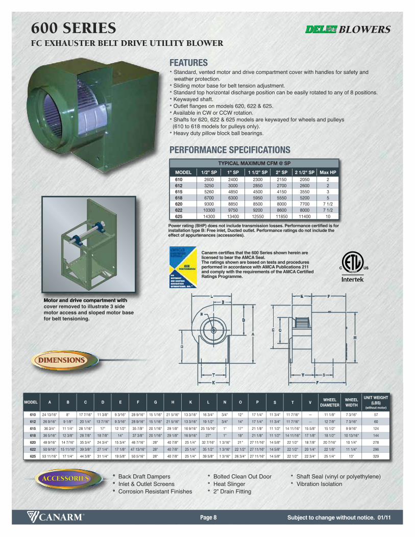
FEATURES• Standard, vented motor and drive compartment cover with handles for safety and
weather protection.• Sliding motor base for belt tension adjustment.• Standard top horizontal discharge position can be easily rotated to any of 8 positions.• Keywayed shaft.• Outlet flanges on models 620, 622 & 625.• Available in CW or CCW rotation.• Shafts for 620, 622 & 625 models are keywayed for wheels and pulleys(610 to 618 models for pulleys only).
• Heavy duty pillow block ball bearings.
600 SERIESFC EXHAUSTER BELT DRIVE UTILITY BLOWER
• Back Draft Dampers• Inlet & Outlet Screens• Corrosion Resistant Finishes
• Bolted Clean Out Door• Heat Slinger• 2” Drain Fitting
• Shaft Seal (vinyl or polyethylene)• Vibration Isolation
OPTIONSOPTIONS
ACCESSORIESACCESSORIES
PERFORMANCE SPECIFICATIONS
MODEL 1/2” SP 1” SP 1 1/2” SP 2" SP 2 1/2" SP Max HP610 2600 2400 2300 2150 2050 2612 3250 3000 2850 2700 2600 2615 5260 4850 4500 4150 3550 3618 6700 6300 5950 5550 5200 5620 9300 8850 8500 8000 7700 7 1/2622 10300 9750 9200 8600 8000 7 1/2625 14300 13400 12550 11850 11400 10
TYPICAL MAXIMUM CFM @ SP
Motor and drive compartment withcover removed to illustrate 3 sidemotor access and sloped motor basefor belt tensioning.
Canarm certifies that the 600 Series shown herein are licensed to bear the AMCA Seal.The ratings shown are based on tests and proceduresperformed in accordance with AMCA Publications 211and comply with the requirements of the AMCA Certified Ratings Programme.
Power rating (BHP) does not include transmission losses. Performance certified is forinstallation type B: Free inlet, Ducted outlet. Performance ratings do not include theeffect of appurtenances (accessories).

Page 9
Canarm certifies that the DSQ-B Seriesshown herein are licensed to bear theAMCA Seal. The ratings shown are basedon tests and procedures performed in accordance with AMCA Publications 211 &311 and comply with the requirements ofthe AMCA Certified Ratings Programme.
ATYP
LxWxH
BTYP
B1TYP A1 TYP
1" TYP
E
Z
1"
A
AB+1/8"
B+1/8"
B+1/8"
B+1/8"
L* X W X H INLET/OUTLET
A B A1 B1 D E
DSQ-B-10 20 1/16"L X 16 1/16"W X 16 1/16"H
14"20 9/13"L X
18 9/16"W X 18 9/16"H19"L X
15"W X 15"H15 1/4" 14 1/4" 62 F-DSQ-10 20 1/16"L X
16 1/16"W X 16 1/16"H14" 6" 7.085 10
DSQ-B-12 20 1/16" 17" 22 9/16" 18 3/4" 15 1/4" 14 1/4" 73 F-DSQ-12 20 1/16" 17" 6" 3.069 13
DSQ-B-13 22 1/16" 18 3/4" 24 9/16" 20 3/4" 15 1/4" 14 1/4" 85 F-DSQ-13 22 1/16" 18 3/4" 6" 2.184 15
DSQ-B-15 24 9/16" 20 7/8" 27" 23" 15 1/4" 14 1/4" 95 F-DSQ-15 24 9/16" 20 7/8" 14" 0.762 26
DSQ-B-16 26 1/16" 23" 28 9/16" 24 3/4" 16 3/4" 16 3/4" 123 F-DSQ-16 26 1/16" 23" 14" 0.630 27
DSQ-B-18 28 11/16" 25 3/8" 31 3/16" 27 1/8" 16 3/4" 16 3/4" 140 F-DSQ-18 28 11/16" 25 3/8" 14" 0.463 30
DSQ-B-20 31 7/16" 27 3/4" 33 7/8" 29 7/8" 16 3/4" 16 3/4" 165 F-DSQ-20 31 7/16" 27 3/4" 14" 0.346 33
DSQ-B-22 34 1/16" 31" 36 9/16" 32 3/4" 21 3/4" 21 3/4" 211 F-DSQ-22 34 1/16" 31" 20" 0.182 57
DSQ-B-24 37 9/16" 34" 40" 36" 21 3/4" 21 3/4" 241 F-DSQ-24 37 9/16" 34" 20" 0.134 64
DSQ-B-27 41 3/8" 37 1/2" 43 13/16" 39 5/16" 21 3/4" 21 3/4" 280 F-DSQ-27 41 3/8" 37 1/2" 20" 0.100 71
*NOTE: With the exception of DSQ-B-10, all models are cubes (DSQ-B-10 has extended length)
BUNIT WEIGHT
(LBS)(without motor)
MOUNTING BRACKET HOLES MOTOR ENCLOSURE
F-DSQ FILTER SECTIONDSQ-B BELT DRIVE BACKWARD INCLINED SQUARE INLINE BLOWER
MODEL MODEL Z FILTER FACTOR
UNIT WEIGHT(LBS)
A
DIMENSIONSDIMENSIONS
OPTIONSOPTIONS
FEATURES• Available in 10” to 27” sizes.• Heavy duty, non-overloading backward inclined wheel.• Pivoted motor mounting base for convenient belt tension adjustment.• Air handler pillow block bearings mounted on rigid angle iron frame.• Leak proof access panels with gasket.• Angle iron mounting lugs can be relocated for base or suspension mounting or positioning motor on the top, side or bottom of blower.
• For side discharge simply re-locate the side panel to the normal discharge opening.
• Motor cover supplied.• Junction box.
DSQ-B SERIESBACKWARD INCLINED BELT DRIVE
SQUARE INLINE BLOWERS
• F-DSQ Filter section with ʻVʼ bank 1" aluminum filters. (Filter rack will acceptcustomer supplied 2" filters).
• Suspension or base mount vibration isolation.
OPTIONSOPTIONS
ACCESSORIESACCESSORIES
PERFORMANCE SPECIFICATIONS
MODEL 1/2” SP 1” SP 1 1/2” SP 2" SP Max HPDSQ-B-10 1700 1500 1300 1100 1DSQ-B-12 2700 2400 2100 1900 1 1/2DSQ-B-13 3100 2800 2400 2000 1 1/2DSQ-B-15 4000 3600 3200 2600 2DSQ-B-16 5400 5000 4600 4000 3DSQ-B-18 6000 5600 5000 4400 3DSQ-B-20 7200 6400 5600 4600 3DSQ-B-22 9500 9000 8300 7500 5DSQ-B-24 12500 12000 11200 10500 7 1/2DSQ-B-27 14500 13500 12500 11000 7 1/2
TYPICAL MAXIMUM CFM @ SP
For more information on Accessories, see page 19.
Unit with motor cover removed.
Mounting brackets shown in both positions.Can be top or bottom mounted.
705
Filter Resistance = Filter Factor x CFM2 x 10-8 in. wg
Subject to change without notice. 01/11
Power rating (BHP) does not include transmission losses. Performance certified is for installationtype B - Free inlet, Ducted Outlet. Performance ratings do not include the effects of appurtenances(accessories).

Subject to change without notice. 01/11Page 10
DIMENSIONSDIMENSIONS
OPTIONSOPTIONS
FEATURES• Available in 10”, 12”, 13” & 15” sizes.• Heavy duty, non-overloading backward inclined wheel.• Leak proof access panels with gasket.• Angle iron mounting lugs can be relocated for base or suspension mounting.• Side discharge option as standard - simply re-locate the side panel to the discharge.• Junction box.• 120V TEAO motor• Two speed motor - DSQ-D-15
DSQ-D SERIESBACKWARD INCLINED DIRECT DRIVE SQUARE INLINE BLOWERS
OPTIONSOPTIONS
ACCESSORIESACCESSORIES
PERFORMANCE SPECIFICATIONS
Canarm certifies that the DSQ-D Series shown herein arelicensed to bear the AMCA Seal. The ratings shown arebased on tests and procedures performed in accordancewith AMCA Publication 211 and AMCA Publication 311and comply with the requirements of the AMCA CertifiedRatings Programme.
Power rating (BHP) does not include transmission losses. Performance certified is forinstallation type B: Free inlet, Ducted outlet. Performance ratings do not include theeffect of appurtenances (accessories).
MODEL 1/2” SP 1” SP 1 1/2” SP 2" SP Max HP
DSQ-D-10 870 390 -- -- 1/4
DSQ-D-12 1630 1220 -- -- 1/2
DSQ-D-13 2280 1800 1120 -- 3/4
DSQ-D-15 3060 2680 3200 1400 1 1/2
TYPICAL MAXIMUM CFM @ SP
B1TYP
A1TYP
BTYP
ATYP
(LxWxH)
1" TYP
H
Z
1"
A
AB+1/8"
B+1/8"
B+1/8"
B+1/8"
Mounting brackets shown in both positions.Can be top or bottom mounted.
Filter Resistance = Filter Factor x CFM2 x 10-8 in. wg
• F-DSQ Filter section with ʻVʼ bank 1" aluminum filters. (Filter rack will acceptcustomer supplied 2" filters).
• Suspension or base mount vibration isolation.
L* X W X HINLET/OUTLET
OVERALL HEIGHT
A B A1 B1 H HP RPM AMPS
DSQ-D-10 20 1/16"L X 16 1/16"W X 16 1/16"H
14" 20 9/13"L X18 9/16"W X 18 9/16"H
19"L X 15"W X 15"H
17 13/16" 1/4 1725 2.8 55 F-DSQ-10 20 1/16"L X 16 1/16"W X 16 1/16"H
14" 6" 7.085 10
DSQ-D-12 20 1/16" 17" 22 9/16" 18 3/4" 21 13/16" 1/2 1725 5.2 77 F-DSQ-12 20 1/16" 17" 6" 3.069 13
DSQ-D-13 22 1/16" 18 3/4" 24 9/16" 20 3/4" 23 13/16" 3/4 1725 13.0 86 F-DSQ-13 22 1/16" 18 3/4" 6" 2.184 15
DSQ-D-15 24 9/16" 20 7/8" 27" 23" 25 5/16" 1 1/2 1725/1140 15.2/8.0 115 F-DSQ-15 24 9/16" 20 7/8" 14" 0.762 26
F-DSQ FILTER SECTIONDSQ-D DIRECT DRIVE BACKWARD INCLINED SQUARE INLINE BLOWER
MODEL MODEL Z FILTER FACTOR
UNIT WEIGHT(LBS)
A
*NOTE: With the exception of DSQ-D-10, all models are cubes (DSQ-D-10 has extended length)
MOTOR NAMEPLATE SPECIFICATIONS B
UNIT WEIGHT (LBS)
(without motor)
MOUNTING BRACKET HOLES

Page 11
Canarm certifies that the 300 Series shown herein arelicensed to bear the AMCA Seal. The ratings shown arebased on tests and procedures performed in accordancewith AMCA Publication 211 and AMCA Publication 311and comply with the requirements of the AMCA CertifiedRatings Programme.
AA
C
B
2”
D*D*
Curb by Others
MODEL A B C * D INSIDESHAFT
DIAMETER
UNIT WEIGHT (LBS)
(without motor & drives)
307 20 3/8" 16 5/8" 9" 20" 3/4" 45
309 24 3/8" 19 3/8" 10 5/8" 24" 3/4" 63
310 28 3/8" 21 3/8" 11 3/8" 28" 3/4" 88
312 32 3/8" 24 5/8" 13 1/8" 32" 3/4" 113
315 36 3/8" 28 3/8" 14 7/8" 36" 1" 156
318 40 3/8" 33 3/4" 17 3/8" 40" 1" 224
MODELDAMPERFACTOR
307 1.520
309 0.469
310 0.175
312 0.167
315 0.052
318 0.033
DIMENSIONSDIMENSIONS
OPTIONSOPTIONS
FEATURES• Square base allows discharge to be oriented in any of 4 directions.• Back draft damper and bird screen included.• Heavy duty ball bearings suitable for -65º to + 250º F.• Cabinet insulated with 1/2” fiberglass insulation.• Low operating RPM of forward curved blowers results in low noise levels.• Quiet operation. Blower is mounted on heavy steel angle with rubber isolators.• Attractive green baked powder coat finish.• Automatic gravity back draft damper and bird screen are included.• Motor receives the cooling benefits of being in the air stream for increasedmotor life.
• Recessed base ensures weather proof mounting to curb.
To estimate back draft damper resistance use the following formula:
S.P. = CFM2 X DAMPER FACTOR1,000,000
Example Model 315, 1500 CFM
S.P. = 1500 X 1500 X 0.052 = 0.117 in. w.g.1,000,000
300 SERIESFORWARD CURVED ROOF EXHAUSTERS
PERFORMANCE SPECIFICATIONS
MODEL 1/2” SP 1” SP 1 1/2” SP 2" SP 2 1/2" SP Max HP
307 1200 1100 900 700 500 3/4
309 1800 1600 1300 1000 700 3/4
310 2800 2500 2200 2000 1600 1 1/2
312 3700 3300 2900 2500 1700 2
315 5700 5200 4600 4100 3400 3
318 8800 8000 7200 6600 5800 5
TYPICAL MAXIMUM CFM @ SP
Easy to service. Blower, motor and drivesaccessible through the convenient removable top.
D is an inside dimension.Curb size must be smaller to allow for flashing.
705
BACK DRAFT DAMPER RESISTANCE CALCULATION
Example
For economical use in schools, hospitals, high rise apartments and many other commercial and industrial applications.
Subject to change without notice. 01/11
Power rating (BHP) does not include transmission losses. Performance certified is forinstallation type B - Free Inlet, Free Outlet. Performance ratings include the effects of theoutlet hood and screen, but do not include the effect of other appurtenances (accessories).
Subject to change without notice. 01/11Page 12
DIMENSIONSDIMENSIONS
OPTIONSOPTIONS
GREEN SERIES 300DDFORWARD CURVED ROOF EXHAUSTERS
AA
C
B
2”
D*D*
Curb by Others
MODEL A B C * D INSIDESHAFT
DIAMETER
UNIT WEIGHT (LBS)
(without motor & drives)
309DD 24 3/8" 19 3/8" 10 5/8" 24" 3/4" 63
310DD 28 3/8" 21 3/8" 11 3/8" 28" 3/4" 88
312DD 32 3/8" 24 5/8" 13 1/8" 32" 3/4" 113
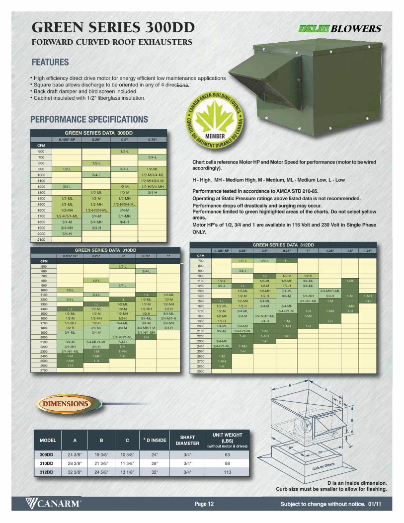
FEATURES
• High efficiency direct drive motor for energy efficient low maintenance applications• Square base allows discharge to be oriented in any of 4 directions.• Back draft damper and bird screen included.• Cabinet insulated with 1/2” fiberglass insulation.
PERFORMANCE SPECIFICATIONS
0.125" SP 0.25" 0.5" 0.75"
CFM
600 1/2-L
700 3/4-L
800 1/2-L
900 1/2-L 3/4-L 1/2-ML
1000 3/4-L 1/2-M/3/4-ML
1100 1/2-MH/3/4-M
1200 3/4-L 1/2-ML 1/2-H/3/4-MH
1300 1/2-ML 1/2-M 3/4-H
1400 1/2-ML 1/2-M 1/2-MH
1500 1/2-ML 1/2-MH 1/2-H/3/4-ML
1600 1/2-MH 1/2-H/3/4-ML 3/4-M
1700 1/2-H/3/4-ML 3/4-M 3/4-MH
1800 3/4-M 3/4-MH 3/4-H
1900 3/4-MH 3/4-H
2000 3/4-H
2100
GREEN SERIES DATA 309DD
0.125" SP 0.25" 0.5" 0.75" 1"
CFM
500 1/2-L
600 3/4-L
700800 1/2-L
900 3/4-L
1000 1/2-L
1100 3/4-L 1-L 1/2-ML
1200 3/4-L 1-L 1/2-ML 1/2-M
1300 1-L 1/2-ML 1/2-M 1/2-MH
1400 1-L 1/2-ML 1/2-M 1/2-MH 1/2-H
1500 1/2-ML 1/2-M 1/2-MH 1/2-H 3/4-ML
1600 1/2-M 1/2-MH 1/2-H 3/4-ML 3/4-M/1-H
1700 1/2-MH 1/2-H 3/4-ML 3/4-M 3/4-MH
1800 1/2-H 3/4-ML 3/4-M 3/4-MH/1-M 3/4-H
1900 3/4-ML 3/4-M 3/4-H/1-MH
2000 3/4-MH/1-ML 1-H
2100 3/4-M 3/4-MH/1-ML 3/4-H
2200 3/4-MH 3/4-H 1-M
2300 3/4-H/1-ML 1-M 1-MH
2400 1-M 1-MH 1-H
2500 1-MH 1-H
2600 1-H
2700
GREEN SERIES DATA 310DD 0.125" SP 0.25" 0.5" 0.75" 1" 1.25" 1.5" 1.75"
CFM
700 1/2-L 3/4-L 1-L
800
900 3/4-L
1000 1-L 1/2-M 1/2-H
1100 1/2-L 1/2-ML 1/2-MH 3/4-ML 1-ML
1200 3/4-L 1-L 1/2-M 1/2-H 3/4-ML
1300 1/2-ML 1/2-MH 3/4-ML 3/4-MH/1-ML
1400 1/2-M 1/2-H 3/4-M 3/4-MH 3/4-H 1-M 1-MH
1500 1-L 1/2-MH 3/4-ML 3/4-H/1-ML 1-M 1-H
1600 1/2-ML 1/2-H 3/4-M 3/4-MH 1-MH
1700 1/2-M 3/4-ML 3/4-H/1-ML 1-M 1-MH 1-H
1800 1/2-MH 3/4-M 3/4-MH/1-ML 1-MH
1900 1/2-H 3/4-H 1-M 1-H
2000 3/4-ML 3/4-MH 1-MH 1-H
2100 3/4-M 3/4-H/1-ML 1-M
2200 1-M 1-MH 1-H
2300 3/4-MH 1-H
2400 3/4-H/1-ML 1-MH
2500 1-H
2600 1-M
2700 1-MH
2800 1-H
2900
GREEN SERIES DATA 312DD
D is an inside dimension.Curb size must be smaller to allow for flashing.
Chart cells reference Motor HP and Motor Speed for performance (motor to be wiredaccordingly).
H - High, MH - Medium High, M - Medium, ML - Medium Low, L - Low
Performance tested in accordance to AMCA STD 210-85.Operating at Static Pressure ratings above listed data is not recommended. Performance drops off drastically and surging may occur.Performance limited to green highlighted areas of the charts. Do not select yellowareas.Motor HPʼs of 1/2, 3/4 and 1 are available in 115 Volt and 230 Volt in Single PhaseONLY.

Page 13
SIZE QUANTITY
709 24 3/8" 32 3/8" 24 3/8" 10 1/4" 11 13/16" 6 9/32" 7 1/16" 7 1/16" 10 1/4" 10"x 20" 4 24"x 24" 84710 28 3/8" 38 1/2" 28 1/4" 11 3/8" 13 1/8" 7 5/8" 8 1/2" 8 1/2" 12 1/4" 12"x 24" 4 28"x 28" 108712 32 3/8" 42 5/8" 31 3/8" 13 7/16" 15 5/8" 8 3/8" 9 15/32" 9 15/32" 16 1/2" 16"x 25" 4 32"x 32" 150715 32 3/8" 42 5/8" 31 3/8" 15 7/8" 18 5/8" 6 7/8" 6 1/4" 10 1/4" 16 1/2" 16"x 25" 4 32"x 32" 155718 36 3/8" 48 5/16" 37 1/4" 18 7/8" 21 7/8" 7 1/4" 6" 11 1/2" 20 3/4" 20"x 28 1/2" 4 36"x 36" 245
H J*INSIDECABINET
UNITWEIGHT (LBS)
(without motor & drives)
FILTERSMODEL A B C D E F G
* Curb size to be smaller than inside cabinet to allow for flashing and roofing.
For use in restaurants, schools, high rise apartments and many other commercial and industrial applications.
B B
J
2"
C
A
A
G
H
D
F E F5/16" HOLES FORFASTENING TO CURB BOTTOM VIEW
DIMENSIONSDIMENSIONS
OPTIONSOPTIONS
FEATURES• Green, weather resistant baked powder coat finish.• Heavy duty ball bearings suitable for -65º to +250º F.• Latched top cover provides convenient service access to 4 filters, motor and drive.• Flexible forward curved belt drive blowers operate at low speed and noise levels.• Blower is rubber mounted for quiet operation.• Four permanent, washable, aluminum filters have large surface area for efficient filtration.• Outside air flows over the motor to increase motor life.• Top insulated with 1/2" fiberglass flexible duct liner.• Adaptable to heating or cooling coils for applications requiring tempered air.• Motor mounting hardware supplied with all units.
Use 9200 Series Duct Blower with matching “H” Series Intake Hood.Refer to page (9200 Series - page 3).
700 SERIESFILTERED FRESH AIR SUPPLY UNITS
PERFORMANCE SPECIFICATIONS
MODEL 1/2” SP 1” SP 1 1/2” SP 2" SP 2 1/2" SP Max HP709 2600 2500 2300 2100 1800 1 1/2710 3200 2900 2600 2300 2000 1 1/2712 4400 4000 3600 3100 2600 2715 5800 5400 4600 4000 3400 3718 8800 8200 7400 6800 6000 5
TYPICAL MAXIMUM CFM @ SP
Motor and drive compartment withcover removed to illustrate 3 sidemotor access and sloped motor basefor belt tensioning.
Canarm certifies that the 700 Series shown herein are licensed to bear the AMCA Seal.The ratings shown are based on tests and proceduresperformed in accordance with AMCA Publications 211 &311and comply with the requirements of the AMCA Certified Ratings Programme.
Power rating (BHP) does not include transmission losses. Performance certified is forinstallation type B: Free inlet, Ducted outlet. Performance ratings do not include theeffect of appurtenances (accessories).
705
FOR HORIZONTAL APPLICATIONS
9200 SERIES WITH INTAKE HOOD
Subject to change without notice. 01/11

Page 14
SIZE QUANTITY
709 24 3/8" 32 3/8" 24 3/8" 10 1/4" 11 13/16" 6 9/32" 7 1/16" 7 1/16" 10 1/4" 10"x 20" 4 24"x 24" 84710 28 3/8" 38 1/2" 28 1/4" 11 3/8" 13 1/8" 7 5/8" 8 1/2" 8 1/2" 12 1/4" 12"x 24" 4 28"x 28" 108712 32 3/8" 42 5/8" 31 3/8" 13 7/16" 15 5/8" 8 3/8" 9 15/32" 9 15/32" 16 1/2" 16"x 25" 4 32"x 32" 150715 32 3/8" 42 5/8" 31 3/8" 15 7/8" 18 5/8" 6 7/8" 6 1/4" 10 1/4" 16 1/2" 16"x 25" 4 32"x 32" 155718 36 3/8" 48 5/16" 37 1/4" 18 7/8" 21 7/8" 7 1/4" 6" 11 1/2" 20 3/4" 20"x 28 1/2" 4 36"x 36" 245
H J*INSIDECABINET
UNITWEIGHT (LBS)
(without motor & drives)
FILTERSMODEL A B C D E F G
* Curb size to be smaller than inside cabinet to allow for flashing and roofing.
B B
J
2"
C
A
A
G
H
D
F E F5/16" HOLES FORFASTENING TO CURB BOTTOM VIEW
DIMENSIONSDIMENSIONS
OPTIONSOPTIONS
GREEN SERIES 700DDFILTERED FRESH AIR SUPPLY UNITS
FEATURES• High efficiency direct drive motor for energy efficient low maintenance applications.• Green, weather resistant baked powder coat finish.• Latched top cover provides convenient service access to 4 filters.• Flexible forward curved belt drive blowers operate at low speed and noise levels.
PERFORMANCE SPECIFICATIONS
0.125" SP 0.25" 0.5" 0.75"CFM600 1/2-L700800 1/2-L 3/4-L900 1/2-L 3/4-L10001100 3/4-L 1-L1200 3/4-L 1-L 1/2-ML1300 1-L 1/2-ML 1-2-M 1400 1-L 1/2-ML 1/2-M 1/2-MH1500 1/2-ML 1/2-M 1/2-MH 1/2-H/3/4-ML1600 1/2-M 1/2-MH 1/2-H 3/4-M/1-M1700 1/2-MH 1/2-H 3/4-ML 3/4-MH/1-MH1800 1/2-H 3/4-ML 3/4-M 3/4-H/1-H1900 3/4-ML 3/4-M 3/4-MH/1-ML2000 3/4-M 3/4-MH/1-ML 3/4-H/1-M2100 3/4-MH/1-ML 3/4-H 1-MH2200 3/4-H 1-M 1-H2300 1-M 1-MH2400 1-MH 1-H2500 1-H2600
GREEN SERIES DATA 709DD
0.125" SP 0.25" 0.5" 0.75" 1" 1.25"CFM600 1/2-L 3/4-L700800 1/2-L 3/4-L 1-L900 1-L1000 1/2-L 3/4-L11001200 3/4-L 1-L 1/2-ML 3/4-ML1300 3/4-L 1/2-ML 1/2-M 1/2-MH/3/4-M1400 1-L 1/2-ML 1/2-M 1/2-MH 1/2-H/3/4-MH1500 1-L 1/2-ML 1/2-M 1/2-MH 1/2-H 3/4-H1600 1/2-ML 1/2-M 1/2-MH 1/2-H 3/4-ML1700 1/2-M 1/2-MH 1/2-H 3/4-ML1800 1/2-MH 1/2-H 3/4-ML 3/4-M 1-ML1900 1/2-H 3/4-ML 3/4-M 3/4-MH/1-ML2000 3/4-ML 3/4-M 3/4-MH/1-ML 3/4-H 1-M2100 3/4-M 3/4-MH/1-ML 3/4-H 1-M 1-MH2200 3/4-M 3/4-MH/1-ML 3/4-H 1-M 1-H2300 3/4-MH/1-ML 3/4-H 1-M 1-MH2400 3/4-H 1-M 1-M 1-MH 1-H2500 1-M 1-MH 1-H2600 1-MH 1-H2700 1-MH 1-H2800
GREEN SERIES DATA 710DD 0.125" SP 0.25" 0.5" 0.75" 1" 1.25" 1.5" 1.75"CFM700 3/4-L 1-L800 1/2-L 3/4-L900
1000 1/2-L 1-L1100 3/4-L 1/2-M1200 1-L 1/2-ML1300 3/4-L 1/2-M 1/2-MH1400 1-L 1/2-ML1500 1-L 1/2-ML 1/2-M 1/2-MH 1/2-H/3/4-ML1600 1/2-ML 1/2-M 1/2-MH 1/2-H 3/4-M 1-ML1700 1/2-M 1/2-MH 1/2-H 3/4-ML 3/4-M 3/4-MH 3/4-H1800 1/2-MH 1/2-H 3/4-ML 3/4-M 1-ML1900 1/2-H 3/4-ML 3/4-MH/1-ML 3/4-H 1-M 2000 3/4-ML 3/4-M 3/4-MH/1-ML 3/4-H 1-ML 1-MH2100 3/4-M 3/4-MH/1-ML 3/4-H 1-M 1-MH 1-H2200 3/4-M 3/4-MH/1-ML 3/4-H 1-M 1-MH 1-H2300 3/4-MH/1-ML 3/4-H 1-M 1-MH 1-H2400 3/4-H 1-MH 1-H2500 1-M 1-MH 1-H2600 1-M 1-MH 1-H2700 1-MH 1-H2800 1-H2900
GREEN SERIES DATA 712DD
Chart cells reference Motor HP and Motor Speed for performance (motor to be wiredaccordingly).H - High, MH - Medium High, M - Medium, ML - Medium Low, L - Low
Performance tested in accordance to AMCA STD 210-85.Operating at Static Pressure ratings above listed data is not recommended. Performance drops off drastically and surging may occur.Performance limited to green highlighted areas of the charts. Do not select yellow areas.Motor HPʼs of 1/2, 3/4 and 1 are available in 115 Volt and 230 Volt in Single Phase ONLY.
Subject to change without notice. 01/11
Page 15
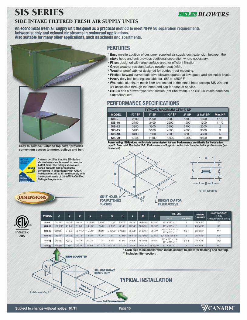
An economical fresh air supply unit designed as a practical method to meet NFPA 96 separation requirementsbetween supply and exhaust air streams in restaurant applications. Also suitable for many other applications, such as schools and apartments.
A
A
FEF
G
D
H
AA
BZ
L
REMOVE CAP FORFILTER ACCESS
2"Ø5/16" HOLES FOR FASTENINGTO CURB
BOTTOM VIEWM
Power rating (BHP) does not include transmission losses. Performance certified is for installationtype B: Free inlet, Ducted outlet. Performance ratings do not include the effect of appurtenances (ac-cessories).
TYPICAL INSTALLATION
BIRM EXHAUSTER
SIS SIDE INTAKESUPPLY UNIT
Roof Curb and Cap *
Intake DuctExtension **
Duct Extension Support
SIZE QUANTITY
SIS-9 24 3/8" 19 3/8" 10 1/4" 11 13/16" 6 9/32" 7 1/16" 7 1/16" 19 1/4" 16 9/16" 21 1/4" 16" x 24" x 1" 1 24"x 24" 70
SIS-10 28 3/8" 21 3/8" 11 3/8" 13 1/8" 7 5/8" 8 1/2" 8 1/2" 20 1/2" 18 9/16" 25 3/4" 15" x 20" x 1" 2 28"x 28" 87
SIS-12 32 3/8" 24 5/8" 13 7/16" 15 5/8" 8 3/8" 9 15/32" 9 15/32" 25 3/8" 21 9/16" 30 3/4"20" x 25" x 1" &16" x 25" x 1"
1 & 1 32"x 32" 117
SIS-15 36 3/8" 28 3/8" 15 7/8" 18 5/8" 8 7/8" 8" 12 1/2" 31 3/16" 25 13/16" 33 1/2" 20" x 28 1/2" x 1" 2 36"x 36" 175
SIS-18 36 3/8" 42 1/2" 18 7/8" 21 7/8" 7 1/4" 6 1/4" 11 1/4" 35 5/8" 32 11/16" 40 1/4"20" x 25" x 1" &16" x 25" x 1"
2 & 2 36"x 36" 262
SIS-20 44 3/8" 49" 24 3/4" 24 3/4" 9 13/16" 5 3/16" 14 7/16" 38 5/8" 35 9/16" 45 1/2"** 20" x 25" x 1" 6 44"x 44" 497
MODEL ZFILTERS *INSIDE
CABINET
UNIT WEIGHT (LBS)
(without motors & drives)
A B D E F G H L M
DIMENSIONSDIMENSIONS
OPTIONSOPTIONS
FEATURES• Easy on-site addition of customer supplied air supply duct extension between the intake hood and unit provides additional separation where necessary.
• Filters designed with large surface area for efficient filtration.• Green weather resistant baked powder coat finish.• Weather proof cabinet designed for outdoor roof mounting.• Flexible forward curved belt drive blowers operate at low speed and low noise levels.• Heavy duty ball bearings suitable for -65º to +250º F.• Washable aluminum mesh filter are located in the intake hood (except SIS-20) andare accessible through the hood end cap for ease of service.
• SIS-20 has a drawer type filter section (not illustrated). The SIS-20 intake hood has a screened inlet.
PERFORMANCE SPECIFICATIONS
MODEL 1/2” SP 1” SP 1 1/2” SP 2" SP 2 1/2" SP Max HPSIS-9 2300 2200 2000 1800 1600 1 1/2SIS-10 2700 2400 2200 1900 1700 1 1/2SIS-12 3800 3500 3100 2700 2300 2SIS-15 5400 5100 4500 4000 3300 3SIS-18 8400 7800 7000 6200 4600 5SIS-20 12500 11700 10900 10300 9500 10
TYPICAL MAXIMUM CFM @ SP
Easy to service. Latched top cover providesconvenient access to motor, pulleys and belt.
705
* Curb size to be smaller than inside cabinet to allow for flashing and roofing.** Includes filter section.
Canarm certifies that the SIS Seriesshown herein are licensed to bear theAMCA Seal. The ratings shown arebased on tests and procedures performed in accordance with AMCAPublications 211 & 311 and comply withthe requirements of the AMCA CertifiedRatings Programme.
SIS SERIESSIDE INTAKE FILTERED FRESH AIR SUPPLY UNITS
Subject to change without notice. 01/11

Page 16
A
A
FEF
G
D
H
AA
BZ
L
REMOVE CAP FORFILTER ACCESS
2"Ø5/16" HOLES FOR FASTENINGTO CURB
BOTTOM VIEWM
SIZE QUANTITY
SIS-9DD 24 3/8" 19 3/8" 10 1/4" 11 13/16" 6 9/32" 7 1/16" 7 1/16" 19 1/4" 16 9/16" 21 1/4" 16" x 24" x 1" 1 24"x 24" 70
SIS-10DD 28 3/8" 21 3/8" 11 3/8" 13 1/8" 7 5/8" 8 1/2" 8 1/2" 20 1/2" 18 9/16" 25 3/4" 15" x 20" x 1" 2 28"x 28" 87
SIS-12DD 32 3/8" 24 5/8" 13 7/16" 15 5/8" 8 3/8" 9 15/32" 9 15/32" 25 3/8" 21 9/16" 30 3/4"20" x 25" x 1" &16" x 25" x 1"
1 & 1 32"x 32" 117
FILTERS *INSIDECABINET
UNIT WEIGHT (LBS)
(without motors & drives)H L M ZMODEL A B D E F G
DIMENSIONSDIMENSIONS
OPTIONSOPTIONS
FEATURES• High efficiency direct drive motor for energy efficient low maintenance applications.• Side intake provides a means to meet supply and exhaust air separation in
restaurant applications.• Easy on-site addition of customer supplied air supply duct extension provides
additional separation where necessary.• Filters designed with large surface area for efficient filtration.• Green weather resistant baked powder coat finish.
GREEN SERIES SISDDSIDE INTAKE FILTERED FRESH AIR SUPPLY UNITS
PERFORMANCE SPECIFICATIONS
* Curb size to be smaller than inside cabinet to allow for flashing and roofing.** Includes filter section.
0.125" SP 0.25" 0.5" 0.75"CFM700 1/2-L 3/4-L800 1/2-L 1/2-ML900 1/2-L 3/4-L 1/2-M 1000 1/2-MH1100 3/4-L 1/2-H/3/4-ML1200 3/4-L 1/2-ML 3/4-MH1300 1/2-M 3/4-H1400 1/2-ML 1/2-MH/3/4-ML1500 1/2-ML 1/2-M 1/2-H/3/4-M1600 1/2-M 1/2-MH/3/4-ML 3/4-MH1700 1/2-MH/3/4-ML 1/2-H/3/4-M 3/4-H1800 1/2-H/3/4-M 3/4-MH1900 3/4-MH 3/4-H2000 3/4-H 2100
GREEN SERIES DATA SIS9DD
0.125" SP 0.25" 0.5" 0.75" 1"CFM500 1/2-L600700 1/2-L800 1/2-L 3/4-L900
1000 1/2-L 3/4-L1100 3/4-L 1-L 1/2-ML1200 3/4-L 1-L 1/2-M/3/4-ML1300 1-L 1/2-ML 1/2-MH/3/4-M/1-ML1400 1-L 1/2-ML 1/2-M 1/2-H/3/4-MH/1-M1500 1/2-ML 1/2-M 1/2-MH 3/4-H/1-MH1600 1/2-ML 1/2-M 1/2-MH 1/2-H 1-H1700 1/2-M 1/2-MH 1/2-H 3/4-ML1800 1/2-MH 1/2-H 3/4-ML 3/4-M 1900 1/2-H 3/4-ML 3/4-M 3/4-MH/1-ML2000 3/4-ML 3/4-M 3/4-MH/1-ML 3/4-H/1-M2100 3/4-M 3/4-MH/1-ML 3/4-H/1-M 1-MH2200 3/4-MH/1-ML 3/4-H/1-M 1-MH 1-H2300 3/4-H/1-M 1-MH 1-H2400 1-MH 1-H2500 1-H2600
GREEN SERIES DATA SIS10DD0.125" SP 0.25" 0.5" 0.75" 1" 1.25" 1.5" 1.75"
CFM500 1/2-L600 3/4-L 1-L700800 1/2-L 1-L900 3/4-L
1000 1/2-L1100 3/4-L 1-L1200 1/2-ML 1/2-M1300 3/4-L 1-L1400 1-L 1/2-ML 1/2-M 1/2-MH 1-ML1500 1/2-ML 1/2-M 1/2-MH 1/2-H1600 1/2-ML 1/2-M 1/2-MH 1/2-H 3/4-ML 1-ML 1-M 3/4-H1700 1/2-M 1/2-MH 1/2-H 3/4-ML 1-ML 3/4-M 3/4-MH 1-MH1800 1/2-MH 1/2-H 3/4-ML 1-ML 3/4-M 3/4-MH/1-M 3/4-H1900 1/2-H 3/4-ML 1-ML 3/4-M 3/4-MH/1-M 3/4-H 1-MH 1-H2000 3/4-ML 1-ML 3/4-M 3/4-MH/1-M 3/4-H 1-MH 1-H2100 3/4-MH 3/4-M 3/4-MH/1-M 3/4-H 1-MH 1-H2200 1-ML 3/4-MH/1-M 3/4-H 1-MH 1-H2300 3/4-MH/1-M 3/4-H 1-MH 1-H2400 3/4-H 1-MH 1-H2500 1-MH 1-H2600 1-H2700
GREEN SERIES DATA SIS12DD
Chart cells reference Motor HP and Motor Speed for performance (motor to be wired accordingly).H - High, MH - Medium High, M - Medium, ML - Medium Low, L - Low
Performance tested in accordance to AMCA STD 210-85.Operating at Static Pressure ratings above listed data is not recommended. Performance drops off drastically and surging may occur.Performance limited to green highlighted areas of the charts. Do not select yellow areas.Motor HPʼs of 1/2, 3/4 and 1 are available in 115 Volt and 230 Volt in Single Phase ONLY.
Subject to change without notice. 01/11
Page 17
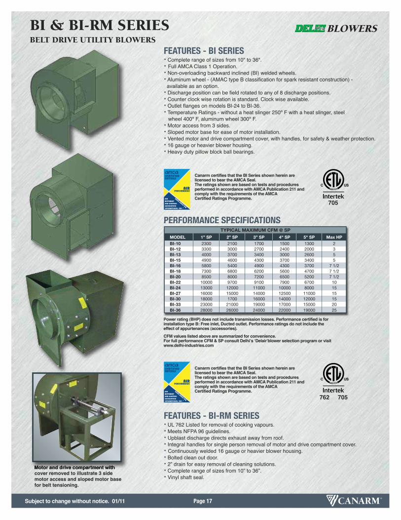
FEATURES - BI SERIES• Complete range of sizes from 10" to 36".• Full AMCA Class 1 Operation.• Non-overloading backward inclined (BI) welded wheels.• Aluminum wheel - (AMAC type B classification for spark resistant construction) - available as an option.
• Discharge position can be field rotated to any of 8 discharge positions.• Counter clock wise rotation is standard. Clock wise available.• Outlet flanges on models BI-24 to BI-36.• Temperature Ratings - without a heat slinger 250º F with a heat slinger, steel
wheel 400º F, aluminum wheel 300º F.• Motor access from 3 sides.• Sloped motor base for ease of motor installation.• Vented motor and drive compartment cover, with handles, for safety & weather protection.• 16 gauge or heavier blower housing.• Heavy duty pillow block ball bearings.
FEATURES - BI-RM SERIES• UL 762 Listed for removal of cooking vapours.• Meets NFPA 96 guidelines.• Upblast discharge directs exhaust away from roof.• Integral handles for single person removal of motor and drive compartment cover.• Continuously welded 16 gauge or heavier blower housing.• Bolted clean out door.• 2” drain for easy removal of cleaning solutions.• Complete range of sizes from 10” to 36”.• Vinyl shaft seal.
BI & BI-RM SERIESBELT DRIVE UTILITY BLOWERS
PERFORMANCE SPECIFICATIONS
MODEL 1” SP 2” SP 3” SP 4" SP 5" SP Max HPBI-10 2300 2100 1700 1500 1300 2BI-12 3300 3000 2700 2400 2000 3BI-13 4000 3700 3400 3000 2600 5BI-15 4900 4600 4300 3700 3400 5BI-16 5800 5400 4900 4300 3700 7 1/2BI-18 7300 6800 6200 5600 4700 7 1/2BI-20 8500 8000 7200 6500 5200 7 1/2BI-22 10000 9700 9100 7900 6700 10BI-24 13000 12000 11000 10000 8000 15BI-27 16000 15000 14000 12500 11000 15BI-30 18000 1700 16000 14000 12000 15BI-33 23000 21000 19000 17000 15000 20BI-36 28000 26000 24000 22000 19000 25
TYPICAL MAXIMUM CFM @ SP
Canarm certifies that the BI Series shown herein are licensed to bear the AMCA Seal.The ratings shown are based on tests and proceduresperformed in accordance with AMCA Publication 211 andcomply with the requirements of the AMCA Certified Ratings Programme.
Canarm certifies that the BI Series shown herein are licensed to bear the AMCA Seal.The ratings shown are based on tests and proceduresperformed in accordance with AMCA Publication 211 andcomply with the requirements of the AMCA Certified Ratings Programme.
705
705762
Power rating (BHP) does not include transmission losses. Performance certified is forinstallation type B: Free inlet, Ducted outlet. Performance ratings do not include theeffect of appurtenances (accessories).
CFM values listed above are summarized for convenience.For full performance CFM & SP consult Delhiʼs ʻDelairʼblower selection program or visitwww.delhi-industries.com
Motor and drive compartment withcover removed to illustrate 3 sidemotor access and sloped motor basefor belt tensioning.
Subject to change without notice. 01/11
Page 18
SHAFTDIA.
INLET
MODELA
(STANDARD MODELS)
A(BI-RM
MODELS)
B C D E F G HK
(CABINET WIDTH)
L N O P S T VUNIT
WEIGHT (LBS)
BI-10 26 3/4" 23 5/8" 8 3/8" 18 15/16" 11 5/16" 8 1/4" 27 3/4"No Leg on BI-10
15 1/4" 21 5/16" 13 3/16" 17 3/8" 3/4" 11" 17 1/4" 11 3/4" 11 7/16" -- 78
BI-12 33 1/16" 30 1/16" 10" 22 1/4" 13" 9 7/8" 33 1/4" 20 1/16" 29 1/8" 16 9/16" 20 1/2" 1" 12 7/16" 21 1/8" 11 1/2" 14 11/16" 13 1/8" 112
BI-13 34 5/16" 30 13/16" 10 3/4" 24 1/2" 14 3/8" 10 3/4" 34 1/8" 20 1/16" 29 1/8" 16 9/16" 22 1/2" 1" 14 3/8" 21 1/8" 11 1/2" 14 11/16" 14" 134
BI-15 35 13/16" 31 13/16" 11 3/4" 27" 15 3/4" 12" 35 3/8" 20 1/16" 29 1/8" 16 9/16" 24 11/16" 1" 15 7/8" 21 1/8" 11 1/2" 14 11/16" 15 1/4" 140
BI-16 39 3/8" 34 11/16" 12 11/16" 29 7/8" 17 5/8" 13 1/8" 36 1/2" 22" 31" 16 9/16" 26 7/8" 1 3/16" 17 3/8" 21 1/8" 11 1/2" 14 11/16" 16 3/8" 162
BI-18 41 1/4" 35 13/16" 13 13/16" 33" 19 3/8" 14 1/2" 37 7/8" 22" 31" 16 9/16" 29 5/8" 1 3/16" 19 3/8" 21 1/8" 11 1/2" 14 11/16" 17 3/4" 172
BI-20 49 1/8" 42 15/16" 14 15/16" 36 1/4" 21 1/4" 15 3/4" 46 7/16" 28" 40 7/8" 25 1/4" 32 1/4" 1 3/16" 21 1/4" 27 11/16" 14 5/8" 22 3/4" 19 3/4" 289
BI-22 51 1/2" 44 3/8" 16 3/8" 40 3/8" 23 5/8" 17 5/8" 48 5/16" 28" 40 7/8" 25 1/4" 35 5/8" 1 3/16" 23 5/8" 27 11/16" 14 5/8" 22 3/4" 21 5/8" 322
BI-24 57 7/8" 49 13/16" 17 13/16" 44 3/8" 26" 19 3/8" 51 5/16" 32" 46 1/2" 28 15/16" 39" 1 7/16" 26" 28 15/16" 18 5/16" 25 1/2" 23 3/8" 385
BI-27 60 1/2" 51 7/16" 19 7/16" 48 7/8" 28 5/8" 21 1/4" 53 3/16" 32" 46 1/2" 28 15/16" 42 3/4" 1 7/16" 28 5/8" 28 15/16" 18 5/16" 25 1/2" 25 1/4" 411
BI-30 65 15/16" 68 3/16" 24 7/8" 54 7/16" 31 3/4" 23 5/8" 57 5/8" 43 5/16" 64 3/4" 43 3/8" 50 3/4" 1 11/16" 31 3/4" 32" 17" 41" 28 9/16" 517
BI-33 68 3/16" 68 9/16" 25 1/4" 59 3/4" 34 7/8" 26" 60" 43 5/16" 64 3/4" 43 3/8" 53 3/4" 1 11/16" 35" 32" 17" 41" 30 15/16" 607
BI-36 70 15/16" 68 15/16" 25 1/2" 66 1/16" 38 5/8" 28 3/4" 62 3/4" 43 7/16" 64 3/4" 43 3/8" 57" 1 15/16" 38 3/4" 32" 17" 41" 33 11/16" 747
OUTLET
L
G
T
K
D
E P
H
SV
F
OA
N
P
FV
N
D
KT
A
G
L O
E
H
S
C
B
L
N
K
T
DA
O
H
F
S V
P E
G
B
C
DIMENSIONSDIMENSIONS
OPTIONSOPTIONS
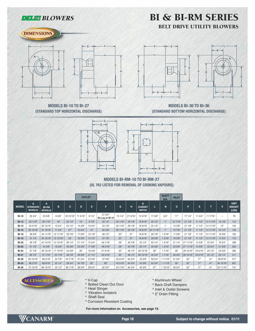
BI & BI-RM SERIESBELT DRIVE UTILITY BLOWERS
MODELS BI-10 TO BI-27(STANDARD TOP HORIZONTAL DISCHARGE)
MODELS BI-RM-10 TO BI-RM-27(UL 762 LISTED FOR REMOVAL OF COOKING VAPOURS)
MODELS BI-30 TO BI-36(STANDARD BOTTOM HORIZONTAL DISCHARGE)
OPTIONSOPTIONS
ACCESSORIESACCESSORIES • V-Cap• Bolted Clean Out Door• Heat Slinger• Vibration Isolators • Shaft Seal• Corrosion Resistant Coating
• Aluminum Wheel• Back Draft Dampers• Inlet & Outlet Screens• 2” Drain Fitting
For more information on Accessories, see page 19.
Subject to change without notice. 01/11
Page 19
BACK DRAFT DAMPER
INLET SCREEN
OUTLET SCREEN
BOLTED CLEAN OUT DOOR
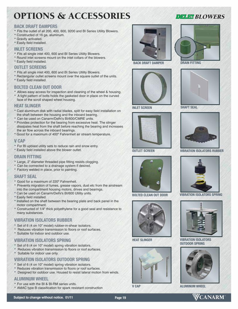
OPTIONS & ACCESSORIES
• Fits the outlet of all 200, 400, 600, 9200 and BI Series Utility Blowers.• Constructed of 16 ga. aluminum.• Gravity activated.• Easily field installed.
BACK DRAFT DAMPERS
• Fits all single inlet 400, 600 and BI Series Utility Blowers.• Round inlet screens mount on the inlet collars of the blowers.• Easily field installed.
INLET SCREENS
• Fits all single inlet 400, 600 and BI Series Utility Blowers.• Rectangular outlet screens mount over the square outlet of the units.• Easily field installed.
OUTLET SCREENS
• Allows easy access for inspection and cleaning of the wheel & housing.• A tight pattern of bolts holds the gasketed door in place on the curved
face of the scroll shaped wheel housing.
BOLTED CLEAN OUT DOOR
• Cast aluminum disk with radial blades, split for easy field installation on the shaft between the housing and the inboard bearing.
• Can be used on Canarm/Delhi's BI/600/CMRE units.• Provides protection for the bearing from excessive heat. The slinger
dissipates heat from the shaft before reaching the bearing and increasesthe air flow across the inboard bearings.
• Good for a maximum of 400º Fahrenheit air stream temperature.
HEAT SLINGER
• Good for a maximum of 220º Fahrenheit.• Prevents migration of fumes, grease vapors, dust etc from the airstream
into the compartment housing motors, drives and bearings.• Can be used on Canarm/Delhi's BI/600 Utility units.• Easily field installed.• Installed on the shaft between the bearing plate and back panel in the
motor compartment.• Constructed of 1/4" thick polyethylene for a good seal and resistance to
many substances.
SHAFT SEAL
• Large, 2” diameter threaded pipe fitting resists clogging.• Can be connected to a drainage system if desired.• Factory welded in place, prior to painting.
DRAIN FITTING
• For BI upblast utility sets to reduce rain and snow entry.• Easily field installed above the blower outlet.
V CAP
• Set of 6 (4 on 10” model) rubber-in-shear isolators.• Reduces vibration transmission to floors or roof surfaces.• Suitable for indoor and outdoor use.
VIBRATION ISOLATORS RUBBER
• Set of 6 (4 on 10” model) spring vibration isolators.• Reduces vibration transmission to floors or roof surfaces.• Suitable for indoor use only.
VIBRATION ISOLATORS SPRING
• Set of 6 (4 on 10” model) spring vibration isolators.• Reduces vibration transmission to floors or roof surfaces.• Designed for outdoor use. Housed to resist lateral motion from winds.
VIBRATION ISOLATORS OUTDOOR SPRING
• For use with the BI & BI-RM series units.• AMAC type B classification for spark resistant construction
ALUMINUM WHEEL
HEAT SLINGER
SHAFT SEAL
DRAIN FITTING
V CAP
VIBRATION ISOLATORS RUBBER
VIBRATION ISOLATORS SPRING
VIBRATION ISOLATORS OUTDOOR SPRING
ALUMINUM WHEEL
Subject to change without notice. 01/11

Subject to change without notice. 01/11Page 20
MODEL - HP A B C D E H LUNIT WEIGHT
(LBS)(without motor & drives)
G9-7-DD-1/3 33
G9-7-DD-1/2 36
G9-DD-1/3 37
G9-DD-1/2 39
G10-8-DD-1/2 40
G10-8DD-3/4 41
G10-DD-1/2 42
G10-DD-3/4 45
G12-9-DD-3/4 22 1/8" 19 1/2" 20 5/8" 13 7/16" 12 1/4" 13 1/4" 16 1/8" 46
G12-10-DD-3/4 22 1/8" 19 1/2" 20 5/8" 13 7/16" 13 1/8" 14 1/8" 16 1/8" 47
16 15/16" 15 1/16" 15 9/16" 10 1/4" 9 3/16" 10 3/16" 11 3/4"
10 1/2"16 3/4"
12 13/16" 11 3/4"11 13/16"
11 1/2" 13 3/8"
13 1/8" 14 1/8" 13 3/8"
16 15/16" 15 1/16" 15 9/16" 10 1/4"
11 3/8"
11 3/8"17 3/8"19"
19" 16 3/4" 17 3/8"
DIMENSIONSDIMENSIONS
OPTIONSOPTIONS
FEATURES• 3 speed, 115V, PSC motor.• Corrosion resistant G90 galvanized housing.• Universal base for 4 position discharge.• Heavy duty, resilient mount, motor mounting bracket.
G-DD SERIESCENTRIFUGAL, FORWARD CURVED, DIRECT DRIVE DWDI BLOWERS
PERFORMANCE SPECIFICATIONS
MODEL - HP 0.5 0.6 0.7 0.8 0.9 1.0 1.2 1.4 1.6
G9-7-DD-1/3 -- -- 1148 1041 841 -- -- -- --
G9-7-DD-1/2 1363 1270 1170 1045 865 -- -- -- --
G9-DD-1/3 -- -- 1213 1025 742 -- -- -- --
G9-DD-1/2 -- 1444 1316 1172 979 -- -- -- --
G10-8-DD-1/2 -- -- -- -- 1372 1238 -- -- --
G10-8DD-3/4 -- -- -- -- -- 1535 800 -- --
G10-DD-1/2 -- -- -- 1514 1335 1115 -- -- --
G10-DD-3/4 -- -- 1665 1581 1486 1379 1000 -- --
G12-9-DD-3/4 -- -- -- -- -- -- 1358 1174 870
G12-10-DD-3/4 -- -- -- -- -- -- 1393 1102 --
CFM @ Medium Speed (see curves for High & Low speed performance)
STATIC PRESSURE - IN W.G.
Heavy DutyResilient MountMotor Mounting Bracket
A
L
B
D
C
E
H

Page 21
E
CD
A
L
BH
L 2
*
EEH 2F 2
MODEL A B C D E H LSHAFT
DIAMETERWHEEL
DIAMETERWHEELWIDTH
UNIT WEIGHT (LBS)(without motor & drives)
G7-5 14 5/16" 12 5/16" 12 11/16" 8 1/4" 6 7/8" 7 7/8" 9 5/8" 3/4" 8 1/16" 4 15/16" 13
G7 14 5/16" 12 5/16" 12 11/16" 8 1/4" 9 3/16" 10 3/16" 9 5/8" 3/4" 8 1/16" 7 3/16" 15
G9-7 16 15/16" 15 1/16" 15 9/16" 10 1/4" 9 3/16" 10 3/16" 11 3/4" 3/4" 10 1/4" 7 3/16" 19
G9 16 15/16" 15 1/16" 15 9/16" 10 1/4" 11 13/16" 12 13/16" 11 3/4" 3/4" 10 1/4" 9 9/16" 21
G10-8 19" 16 3/4" 17 3/8" 11 3/8" 10 1/2" 11 1/2" 13 3/8" 3/4" 11 1/8" 8 1/16" 23
G10 19" 16 3/4" 17 3/8" 11 3/8" 13 1/8" 14 1/8" 13 3/8" 3/4" 11 9/16" 10 13/16" 25
G12-9 22 1/8" 19 1/2" 20 5/8" 13 7/16" 12 1/4" 13 1/4" 16 1/8" 3/4" 12 7/8" 9 9/16" 29
G12 22 1/8" 19 1/2" 20 5/8" 13 7/16" 15 5/8" 16 5/8" 16 1/8" 3/4" or 1" 12 7/8" 12 13/16" 34
G15-10 25 3/4" 22 11/16" 24 1/4" 15 7/8" 14 11/16" 15 11/16" 19 1/2" 1" 15 1/2" 10 13/16" 48
G15 25 3/4" 22 11/16" 241/4" 15 7/8" 18 5/8" 19 5/8" 19 1/2" 1" 15 1/2" 15 1/16" 56
G18-13 30 1/2" 27" 29" 18 7/8" 17 3/8" 18 3/8" 24" 1" 18 1/2" 15 1/16" 67
G18 30 1/2" 27" 29" 18 7/8" 21 7/8" 22 7/8" 24" 1" 18 1/2" 18 1/2" 87
DIMENSIONSDIMENSIONS
OPTIONSOPTIONS
FEATURES• Sleeve or ball bearing models available.• Base feet can be mounted for various discharge positions.• Motor mounting hardware included with each blower.• Corrosion resistant galvanized blower housing.• Capacity range 200 to 8000 CFM.• The blower wheel has an exclusive centre disc which allows blowers to be
used safely at speeds well above any normal requirement.• Blower housings have extruded holes to give greater holding power for
mounting base sides and motor bracket.• Matte finish zinc coated wheel and cut-off baffle.• Available with permanently lubricated sleeve bearings suitable for operation inambient temperatures of +30 to +120 deg. F and under 1000 RPM ORBall bearings with a sealed lifetime supply of lubricant for operation in ambienttemperatures of -65 to +250 deg. F (optional).
• Shaft dimensions and finish are carefully controlled to ensure quiet, trouble freeoperation.
• Shafts for ball bearing models have keywayed ends. Sleeve bearing modelshafts have flats.
G SERIESDOUBLE INLET BELT DRIVE BLOWERS
PERFORMANCE SPECIFICATIONS
MODEL 1/2” SP 1” SP 1 1/2" SP 2" SP 2 1/2" SP
G7-5 1100 1000 950 875 825
G7 3800 3700 3600 3500 3400
G9-7 4400 4300 4200 4100 4000
G9 5100 5000 4900 4800 4700
G10-8 5200 5100 5000 4900 4800
G10 6900 6800 6600 6400 6200
G12-9 7600 7500 7300 7100 6900
G12 8200 8000 7800 7600 7400
G15-10 9000 8600 8400 8200 8000
G15 12000 11500 11250 11000 10500
G18-13 13300 12800 12300 12000 11700
G18 18000 17000 16500 16000 15500
TYPICAL MAXIMUM CFM @ SP
CFM values are listed above are summarized for convenience only. For full performance CFM, SP & HP, consult Delhiʼs ʻDelairʼ blower selection program or visitwww.delhi-industries.com.
“G” Series Twin Units - * Spacing will determine “L2” and “F2” dimensions.
Subject to change without notice. 01/11

Subject to change without notice. 01/11Page 22
MODEL A D E G H J K L M N P RWHEEL
DIAMETERWHEELWIDTH
UNIT WEIGHT (LBS)
(without motor & drives)
809 17 1/4" 10 1/4" 11 13/16" 10 1/8" 12 15/16" 14 1/2" 11 3/4" 14 1/2" 3/4" 3/4" 13 15/16" 1 1/2" 10 1/4" 9 9/16" 28
810 19 1/8" 11 3/8" 13 1/8" 11 1/4" 14 1/4" 16 1/2" 13 3/8" 16 1/4" 3/4" 3/4" 15 1/4" 1 1/2" 11 9/16" 10 13/16" 32
812 22 1/4" 13 7/16" 15 5/8" 13" 16 3/4" 19 5/8" 16 1/4" 19" 3/4" 1" 17 3/4" 1 1/2" 12 7/8" 12 13/16" 43
815 26" 15 7/8" 18 5/8" 15 1/4" 19 3/4" 23 3/8" 19 3/8" 22 1/8" 3/4" 1" 20 3/4" 1 1/2" 15 1/2" 15 1/16" 67
818 30 3/4" 18 7/8" 21 7/8" 17 3/4" 23 1/2" 29" 24 1/2" 26 1/2" 3/4" 1" 25" 1 1/2" 18 1/2" 18 1/2" 125
MODEL A-2SHAFT
LENGTH F-25/8 DIA. MOUNTING
HOLES H-25/8 DIA. MOUNTING
HOLES K-2L-2 N-2 R-2 S-2 T-2 WEIGHT (LBS)
(without motor & drives)
809-2 17 5/8" 39 1/2" 36 5/8" 13 3/8" 14 7/8" 3/4" 1 11/16" 9" 38 3/8" 95
810-2 19 1/2" 44" 40 1/4" 15 1/8" 16 5/8" 3/4" 1 11/16" 10" 42" 112
812-2 22 5/8" 51 1/2" 47 1/4" 17 7/8" 19 3/8" 1" 1 11/16" 12" 49" 130
815-2 26 3/8" 61 3/8" 56 1/4" 21" 22 1/2" 1" 1 11/16" 15" 58" 195
818-2 31 1/8" 72" 66 3/4" 25 1/2" 27" 1" 1 3/4" 18" 68 1/2" 302
DIMENSIONSDIMENSIONS
OPTIONSOPTIONS
FEATURES• Features frame with spider bearing bracket mounts.• Available sizes: 9”, 10”, 12”, 15” and 18” wheel diameters.• Keywayed shaft both ends.• Universal Frame allows for choice of discharge position.• Motor mounting hardware supplied.• Ball bearings are permanently lubricated.• Corrosion resistant galvanized blower housing.• Available as single or twin assemblies.• Matte finish zinc coated steel Delhi 'G' series full width wheel and cut-off baffle.• Frame has green baked enamel finish.• Insert ball bearings with resilient rings.• Bearing brackets are attached with thread cutting screws driven into extruded housing
holes (809) or attached with a bolt and locknut (810 through 818).• Motor mounting bracket is attached to the blower frames on models 809 through 815
and is rated at 3 HP.• Motor mounting bracket/motor plate assembly for 818 and 818-2 models is rated at 5 HP.• Motor mounting and adjusting hardware is packed with each unit. Two adjusting leg sets
are furnished with 815 and 818 models, one only with all others.• Units individually cartoned or skidded for shipment.
800 SERIESDOUBLE WIDTH, DOUBLE INLET BLOWERS - WITH FRAME
PERFORMANCE SPECIFICATIONS
MODEL 1/2” SP 1” SP 1 1/2” SP 2" SP 2 1/2" SP
809 5100 5000 4900 4800 4700
810 6900 6800 6600 6400 6200
812 8200 8000 7800 7600 7400
815 12000 11500 11250 11000 10500
818 18000 17000 16500 16000 15500
MAXIMUM CFM @ SP
A-2
N-2
H-2
ES-2E
T-2
D
R-2
L-2
K-2
F-2E
G
PH
AJD
R
MK
L
MOUNTINGHOLES7/16 X 5/8
N
CFM values are listed above are summarized for convenience only. For full performance CFM, SP & HP, consult Delhiʼs ʻDelairʼ blower selection program or visitwww.delhi-industries.com.
800 SERIES 800-2 SERIES
800 SERIES
800-2 SERIES
Subject to change without notice. 01/11 Page 23
FE
G
H
P
N
UMOUNTINGHOLES
D
R
KM
L
AJ
C B
Q
MODEL A B C D EF
(See Note)
G H J K L MN
(See Note)
P Q R UUNIT WEIGHT
(LBS)(without motor & drives)
907 14 3/8" 6 7/16" 6 1/16" 8 1/4" 9 3/16" 17 3/16" 8 5/8" 10 3/8" 11 5/8" 9" 11 3/4" 3/4" 3/4" 11 3/8" 4 5/8" 1 1/2" 7/16 x 5/8 22
909-7 17 1/4" 7 15/16" 7 5/16" 10 1/4" 9 3/16" 17 3/16" 10 1/8" 10 3/8" 14 1/2" 11 3/4" 14 1/2" 3/4" 3/4" 11 3/8" 5 1/2" 1 1/2" 7/16 x 5/8 27
909 17 1/4" 7 15/16" 7 5/16" 10 1/4" 11 13/16" 19 13/16" 10 1/8" 12 15/16" 14 1/2" 11 3/4" 14 1/2" 3/4" 3/4" 13 15/16" 5 1/2" 1 1/2" 7/16 x 5/8 32
910-8 19 1/8" 9" 8" 11 3/8" 10 1/2" 18 1/2" 11 1/4" 11 5/8" 16 1/2" 13 3/8" 16 1/4" 3/4" 3/4" 12 5/8" 6 1/4" 1 1/2" 7/16 x 5/8 35
910 19 1/8" 9" 8" 11 3/8" 13 1/8" 21 5/8" 11 1/4" 14 1/4" 16 1/2" 13 3/8" 16 1/4" 3/4" 1" 15 1/4" 6 1/4" 1 1/2" 7/16 x 5/8 43
912-9 22 1/4" 10 5/8" 9 1/8" 13 7/16" 12 1/4" 20 3/4" 13" 13 3/8" 19 5/8" 16 1/4" 19" 3/4" 1" 14 3/8" 7 5/16" 1 1/2" 7/16 x 5/8 48
912 22 1/4" 10 5/8" 9 1/8" 13 7/16" 15 5/8" 24 1/8" 13" 16 3/4" 19 5/8" 16 1/4" 19" 3/4" 1" 17 3/4" 7 5/16" 1 1/2" 7/16 x 5/8 59
915-10 26" 12 9/16" 10 5/16" 15 7/8" 14 11/16" 23 3/16" 15 1/4" 15 13/16" 23 3/8" 19 3/8" 22 1/8" 3/4" 1" 16 13/16" 8 5/8" 1 1/2" 7/16 x 5/8 62
915 26" 12 9/16" 10 5/16" 15 7/8" 18 5/8" 27 1/8" 15 1/4" 19 3/4" 23 3/8" 19 3/8" 22 1/8" 3/4" 1" 20 3/4" 8 5/8" 1 1/2" 7/16 x 5/8 76
918-13 30 3/4" 14 15/16" 12 3/8" 18 7/8" 17 3/8" 27 1/8" 17 3/4" 19" 29" 24 1/2" 26 1/2" 3/4" 1 3/16" 20 1/2" 10 3/8" 1 1/2" 7/16 x 5/8 120
918 30 3/4" 14 15/16" 12 3/8" 18 7/8" 21 7/8" 34" 17 3/4" 23 1/2" 29" 24 1/2" 26 1/2" 3/4" 1 3/16" 25" 10 3/8" 1 1/2" 7/16 x 5/8 115
920-18 38" 18 5/16" 14 7/16" 24 3/4" 22 3/4" 35 1/4" 22 9/16" 24 1/4" 32 1/4" 25 1/2" 31 1/4" 1 1/2" 1 3/16" 26 3/4" 11 1/4" 2" 5/8" 202
920 38" 18 5/16" 14 7/16" 24 3/4" 24 3/4" 37 1/4" 22 9/16" 26 1/4" 32 1/4" 25 1/2" 31 1/4" 1 1/2" 1 3/16" 28 3/4" 11 1/4" 2" 5/8" 202
922 41 1/2" 20 1/16" 15 11/16" 27 1/4" 27 1/4" 39 3/4" 24 5/8" 28 3/4" 35 3/4" 28 1/2" 34 1/4" 1 1/2" 1 3/16" 31 1/4" 12 1/4" 2" 5/8" 226
925 46 3/4" 22 5/8" 17 1/4" 31 1/4" 31 1/4" 43 3/4" 27 3/4" 32 3/4" 41" 32 3/4" 38 3/8" 1 1/2" 1 3/16" 35 1/4" 13 1/2" 2" 5/8" 276
927 51 1/2" 25 1/16" 19 1/8" 34 1/4" 34 1/4" 50 1/4" 30 1/4" 35 3/4" 46 1/2" 37 11/16" 42 11/16" 1 1/2" 1 11/16" 38 1/4" 15 1/4" 2" 5/8" 400
930 55 1/2" 27 1/16" 20 5/16" 36 3/4" 36 3/4" 52 3/4" 32 5/8" 38 1/4" 50 1/2" 40 7/8" 45 7/8" 1 1/2" 1 11/16" 40 3/4" 16 3/4" 2" 5/8" 505
933 59 3/4" 29 1/8" 24 5/8" 42 15/16" 39 3/4" 58 3/4" 34 1/4" 41 3/4" 54 3/4" 47 1/4" 52 1/4" 1 1/2" 2 3/16" 43 3/4" 14 13/16" 2" 5/8" 610
936 59 3/4" 29 1/8" 24 5/8" 42 15/16" 42 3/4" 61 3/4" 34 1/4" 44 3/4" 54 3/4" 47 1/4" 52 1/4" 1 1/2" 2 3/16" 46 3/4" 14 13/16" 2" 5/8" 685
DIMENSIONSDIMENSIONS
OPTIONSOPTIONS
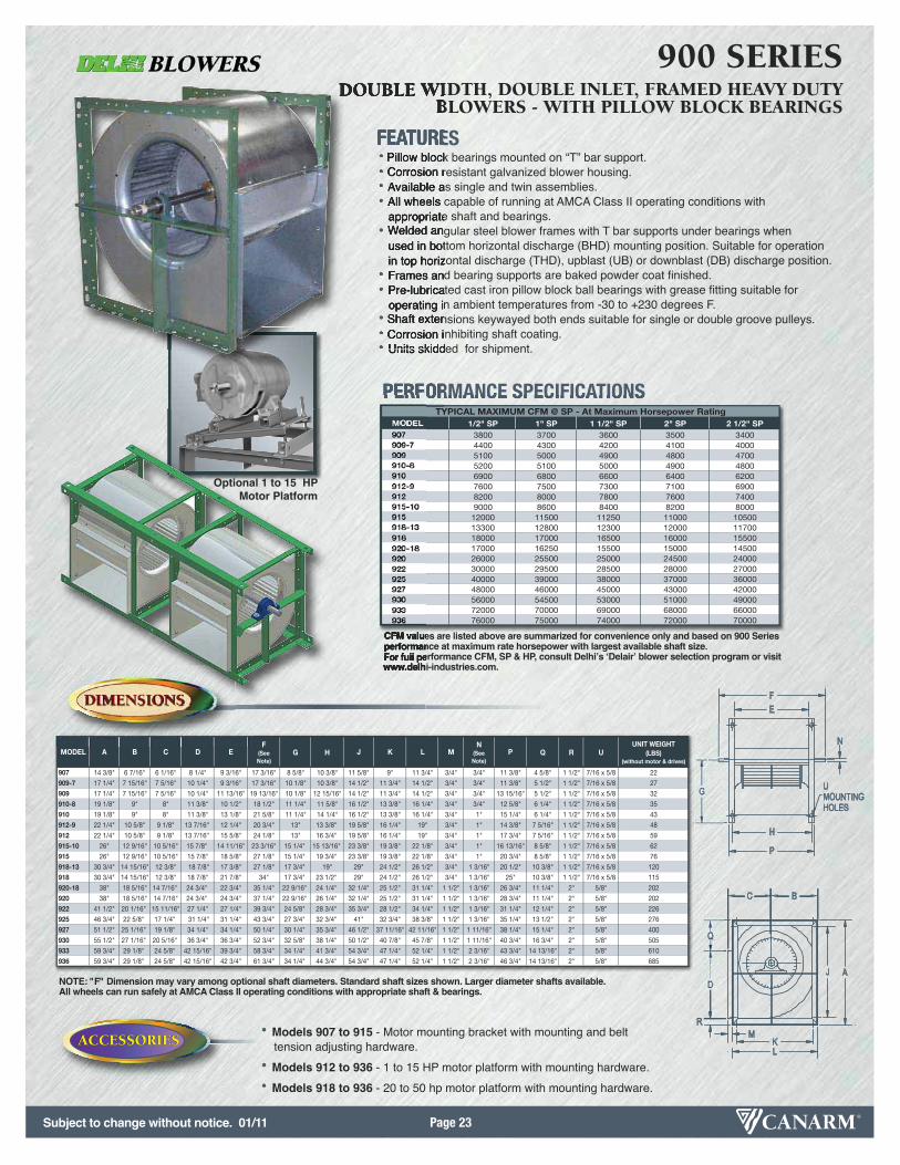
FEATURES• Pillow block bearings mounted on “T” bar support. • Corrosion resistant galvanized blower housing. • Available as single and twin assemblies.• All wheels capable of running at AMCA Class II operating conditions with
appropriate shaft and bearings.• Welded angular steel blower frames with T bar supports under bearings when
used in bottom horizontal discharge (BHD) mounting position. Suitable for operation in top horizontal discharge (THD), upblast (UB) or downblast (DB) discharge position.
• Frames and bearing supports are baked powder coat finished.• Pre-lubricated cast iron pillow block ball bearings with grease fitting suitable for
operating in ambient temperatures from -30 to +230 degrees F.• Shaft extensions keywayed both ends suitable for single or double groove pulleys.• Corrosion inhibiting shaft coating.• Units skidded for shipment.
900 SERIESDOUBLE WIDTH, DOUBLE INLET, FRAMED HEAVY DUTY
BLOWERS - WITH PILLOW BLOCK BEARINGS
PERFORMANCE SPECIFICATIONSMODEL 1/2" SP 1" SP 1 1/2" SP 2" SP 2 1/2" SP907 3800 3700 3600 3500 3400909-7 4400 4300 4200 4100 4000909 5100 5000 4900 4800 4700910-8 5200 5100 5000 4900 4800910 6900 6800 6600 6400 6200912-9 7600 7500 7300 7100 6900912 8200 8000 7800 7600 7400915-10 9000 8600 8400 8200 8000915 12000 11500 11250 11000 10500918-13 13300 12800 12300 12000 11700918 18000 17000 16500 16000 15500920-18 17000 16250 15500 15000 14500920 26000 25500 25000 24500 24000922 30000 29500 28500 28000 27000925 40000 39000 38000 37000 36000927 48000 46000 45000 43000 42000930 56000 54500 53000 51000 49000933 72000 70000 69000 68000 66000936 76000 75000 74000 72000 70000
TYPICAL MAXIMUM CFM @ SP - At Maximum Horsepower Rating
CFM values are listed above are summarized for convenience only and based on 900 Series performance at maximum rate horsepower with largest available shaft size.For full performance CFM, SP & HP, consult Delhiʼs ʻDelairʼ blower selection program or visitwww.delhi-industries.com.
NOTE: "F" Dimension may vary among optional shaft diameters. Standard shaft sizes shown. Larger diameter shafts available. All wheels can run safely at AMCA Class II operating conditions with appropriate shaft & bearings.
OPTIONSOPTIONS
ACCESSORIESACCESSORIES• Models 907 to 915 - Motor mounting bracket with mounting and belt
tension adjusting hardware.
• Models 912 to 936 - 1 to 15 HP motor platform with mounting hardware.
• Models 918 to 936 - 20 to 50 hp motor platform with mounting hardware.
Optional 1 to 15 HP Motor Platform

Subject to change without notice. 01/11Page 24
MODEL A B C D E F G H J K L M N PUNIT WEIGHT
(LBS)(without motor & drives)
BIDI-10 21 1/2" 19 3/8" 8 13/16" 11 1/4" 16 5/8" 29 1/4" 8 1/4" 18 1/4" 14 1/8" 14 1/8" 1 7/8" 2" 1 3/16" 21 3/4" 110
BIDI-12 25 1/16" 21 3/16" 10" 13" 18 1/2" 31 3/4" 9 13/16" 20" 14 1/8" 14 1/8" 2" 2" 1 7/16" 24 1/8" 138
BIDI-13 27 1/8" 23" 10 3/4" 14 3/8" 19 1/8" 31 3/4" 10 3/4" 20 3/4" 21 1/8" 17" 2" 2" 1 7/16" 24 1/4" 149
BIDI-15 29 13/16" 25 5/16" 11 3/4" 15 3/4" 21 3/8" 34" 11 13/16" 23" 21 1/8" 17" 2" 2" 1 7/16" 28 1/2" 177
BIDI-16 32 5/8" 27 1/2" 12 3/4" 17 5/8" 23 1/2" 37 5/8" 13" 25 1/8" 26 5/8" 21 1/2" 2" 2" 1 11/16" 28 5/8" 215
BIDI-18 35 3/4" 30 1/8" 13 7/8" 19 3/8" 25 3/4" 39 7/8" 14 3/8" 27 3/8" 29 3/4" 24 1/8" 2" 2" 1 11/16" 30 7/8" 237
BIDI-20 39" 32 7/8" 15" 21 1/4" 28" 42 1/8" 15 3/4" 29 5/8" 33" 26 7/8" 2" 2" 1 11/16" 33 1/8" 273
BIDI-22 43 1/8" 36 1/8" 16 3/8" 23 5/8" 31 1/8" 46 3/4" 17 3/8" 33 1/4" 40 1/8" 33 1/8" 2" 3" 2 1/4" 37 1/4" 421
BIDI-24 47 1/8" 39 5/8" 17 7/8" 26 1/8" 34 1/8" 49 3/4" 19 1/8" 36 1/4" 44 1/8" 36 5/8" 2" 3" 2 1/4" 40 1/4" 490
BIDI-27 51 5/8" 43 3/8" 19 1/2" 28 5/8" 37 3/4" 53 3/8" 21" 39 7/8" 48 5/8" 40 3/8" 2" 3" 2 1/4" 43 7/8" 565
OUTLET
DIMENSIONSDIMENSIONS
OPTIONSOPTIONS
FEATURES• Welded backwardly inclined blades.• Cold rolled steel housing with green, weather resistant, baked powder coat finish.• Heavy, welded steel “U” channel frames with “T-bar” bearing supports for universal
4 way mounting.• Detachable inlet venturi.• Shafts have corrosion inhibiting coating and are keywayed both ends.• High quality cast iron pillow block bearings with grease fittings for lubrication.
BIDI SERIESDOUBLE WIDTH, DOUBLE INLET BACKWARD INCLINED BLOWERS
PERFORMANCE SPECIFICATIONS
MODEL 1" SP 2" SP 3" SP 4" SP 5" SP MAX HP
BIDI-10 1500 - 4000 5000 4500 4000 3500 3000 7 1/2
BIDI-12 2500 - 5500 6200 5800 5300 4800 4200 7 1/2
BIDI-13 3000 - 6500 7300 6800 6200 5500 4600 7 1/2
BIDI-15 3500 - 7500 8800 8200 7500 6700 5700 10
BIDI-16 4000 - 9500 11000 10200 9400 5800 7400 15
BIDI-18 5000 -11,000 13800 12900 11700 10600 8900 15
BIDI-20 6000 -14,000 16300 15000 13700 12000 9800 15
BIDI-22 8000 -17,000 19300 17900 16000 14100 11700 20
BIDI-24 10,000 -21,000 24700 22800 20500 18000 15600 20
BIDI-27 12,000 -25,000 29500 27300 24700 21700 18000 25
TYPICAL MAXIMUM CFM @ SPTYPICAL CFM RANGE0 TO 5 1/2" SP
KB
AJ
G
F
ML
DN
E
H
P
C
Optional 1 to 15 HP Motor Platform
(20-50 HP available)
OPTIONSOPTIONS
OPTIONSOPTIONS • 1-15 HP motor platform• 20-50 HP motor platform
Power rating (BHP) does not include transmission losses. Performance certified is for installation type B:Free inlet, Ducted outlet. Performance ratings do not include the effect of appurtenances (accessories).
Canarm certifies that the BIDI Seriesshown herein are licensed to bear theAMCA Seal. The ratings shown are basedon tests and procedures performed in accordance with AMCA Publication 211and comply with the requirements of theAMCA Certified Ratings Programme.

Subject to change without notice. 01/11 Page 25
OPTIONSOPTIONS
OPTIONSOPTIONS • Vibration Isolators• Motor base with platform
• Can be bolted directly to the side of the Plenum fan frame (2 locations) or secured to the base of the air handler.
• Sliding platform provides convenient belt tension adjustment.
Power rating (BHP) does not include transmission losses. Performance certified is for installation type B:Free inlet, Ducted outlet. Performance ratings do not include the effect of appurtenances (accessories).
MODEL A F G H K N PUNIT WEIGHT
(LBS)(without motor & drives)
DPL-12 18 3/4" 17 5/8" 9 3/8" 12 1/2" 16 3/4" 1" 14 1/8" 51
DPL-13 20 5/8" 17 5/8" 10 5/16" 12 1/2" 18 5/8" 1" 14 1/8" 57
DPL-15 22 15/16" 18 5/8" 11 15/32" 13 1/2" 20 15/16" 1" 15 1/8" 68
DPL-16 24" 20 1/8" 12" 14-1/2 22" 1 3/16" 16 1/8" 80
DPL-18 & DPL-AF-18 26 9/16" 22 3/4" 13 9/32" 16 13/16" 24 9/16" 1 3/16" 19 1/16" 91
DPL- 20 & DPL-AF-20 29 1/16" 24 1/16" 14 17/32" 18 1/16" 27 1/16" 1 3/16" 20 5/16" 104
DPL-22 & DPL-AF-22 31" 27 1/16" 15 1/2" 20 7/16" 29" 1 7/16" 22 15/16" 148
DPL-24 & DPL-AF-24 34 1/8" 28 5/8" 17 1/16" 22" 32 1/8" 1 7/16" 24 1/2" 185
DPL-27 & DPL-AF-27 37 5/8" 30 7/16" 18 13/16" 23 13/16" 35 5/8" 1 7/16" 26 5/16" 205
DPL-30 & DPL-AF-30 40" 34" 20" 26 3/8" 38" 1 11/16" 29 3/16" 248
DPL-33 & DPL-AF-33 44" 36 15/16" 22" 28 3/8" 42" 1 15/16" 31 3/16" 306
DPL-36 & DPL-AF-36 48 11/16" 39" 24 11/32" 30 7/8" 46 11/16" 1 15/16" 33 11/16" 357
DIMENSIONSDIMENSIONS
OPTIONSOPTIONS
FEATURES• Rigid welded angle iron frame construction.• Full Class II capability.• Min L10 bearing life of 35,000 hrs (average - L50 bearing life of 175,000 hrs).• Standard welded backwardly inclined flat blade wheel for DPL-12 to DPL-36
(Aluminum available as option).• 18” to 36” diameter wheels.• Standard welded aluminum backward inclined airfoil wheel for DPL-30-AF to DPL-36-AF.
DPL & DPL-AF SERIESPLENUM FANS
PERFORMANCE SPECIFICATIONS
MODEL DPL DPL-AF DPL DPL-AF DPL DPL-AF DPL DPL-AF DPL DPL-AF
DPL-12 4300 -- 4000 -- 3600 -- 3000 -- -- --
DPL-13 5200 -- 4700 -- 4000 -- 3000 -- -- --
DPL-15 5900 -- 5200 -- 4200 -- 2800 -- -- --
DPL-16 7600 -- 6800 -- 5700 -- 4200 -- -- --
DPL-18 & DPL-AF-18 7200 9500 6400 8500 2400 7500 -- 6500 -- 4300
DPL- 20 & DPL-AF-20 8800 11500 7600 10500 5200 9000 -- 7200 -- 5000
DPL-22 & DPL-AF-22 12000 14500 9500 13000 4500 11000 -- 9000 -- 7000
DPL-24 & DPL-AF-24 14000 16000 12500 14000 8000 12000 -- 9000 -- 6500
DPL-27 & DPL-AF-27 16000 20000 14000 17000 9000 15000 -- 11500 -- 8000
DPL-30 & DPL-AF-30 20000 25000 18000 22000 12000 18000 -- 15000 -- 10000
DPL-33 & DPL-AF-33 26000 31000 22000 28000 16000 24000 -- 20000 -- 16000DPL-36 & DPL-AF-36 30000 38000 26000 32000 20000 26000 -- 20000 -- 15000
1" SP 3" SP 5" SP 7" SP 9" SP
WHEEL DIAMETERS MAX HP MAX FRAME SIZE
12" TO 20" 10 215T
22" TO 27" 15 254T
30" TO 36" 30 286T
MOTOR PLATFORM
K
A
HP
A
G
G
N
F
MOTOR BASE & PLATFORM
Canarm certifies that the DPLSeries shown herein are licensed to bear the AMCA Seal.The ratings shown are based on tests and procedures performed in accordance with AMCAPublications 211 & 311and comply with the requirements of the AMCA Certified Ratings Programme.
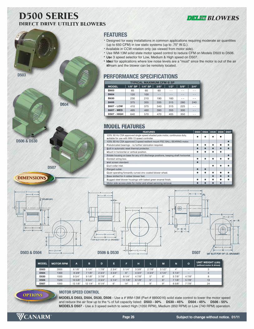
Subject to change without notice. 01/11Page 26
MODEL MOTOR RPM A B D E F H L M N O UNIT WEIGHT (LBS)(without motor & drives)
D503 3000 6 1/8" 5 1/4" 1 7/8" 2 3/4" 5 1/4" 3 3/8" 2 7/8" 3 1/2" 4" -- 3
D504 1300 8 3/8" 7 1/8" 2 3/4" 3 3/4" 6" 4 3/4" 3 3/4" 4 1/4" 5 1/4" -- 4
D530 1550 9 3/4" 9 1/8" 3 7/8" 4" 8 1/4" 4 7/8" 5" 6" 5 7/8" 4 7/8" 8
D506 1520 10 5/8" 9 3/4" 3 3/4" 5 1/4" 11 1/8" 6 1/8" 5" 6" 7 1/8" 5 7/8" 13
D507 1050 13 1/8" 12 1/4" 8 1/4" 6" 14" 5" 8" 9" 6 5/8" 7 7/8" 24
DIMENSIONSDIMENSIONS
OPTIONSOPTIONS
FEATURES• Designed for easy installations in common applications requiring moderate air quantities
(up to 650 CFM) in low static systems (up to .75" W.G.).• Available in CCW rotation only (as viewed from motor side).• Use WM-13M solid state motor speed control to reduce CFM on Models D503 to D506.• Use 3 speed selector for Low, Medium & High speed on D507.• Ideal for applications where low noise levels are a "must" since the motor is out of the air
stream and the blower can be remotely located.
D500 SERIESDIRECT DRIVE UTILITY BLOWERS
PERFORMANCE SPECIFICATIONS
MODEL 1/8” SP 1/4” SP 3/8" 1/2" 5/8" 3/4"
D503 65 60 60 - - - - - -
D504 120 100 - - - - - - - -
D530 230 210 190 160 - - - -
D506 375 355 335 315 280 240
D507 - LOW 410 375 340 315 225 - -
D507 - MED 495 460 390 355 300 - -
D507 - HIGH 640 570 470 405 350 - -
TYPICAL MAXIMUM CFM @ SP
MODEL FEATURESFEATURES D503 D504 D530 D506 D507
120V, 60 Hz CSA approved single speed shaded pole motor, continuous duty, suitable for use with WM-13 speed controller. • • • •120V, 60 Hz CSA approved 3 speed resilient mount PSC BALL BEARING motor. •Prelubricated bearings - no further lubrication required. • • • • •Built in automatic reset thermal protector. • • • • •Mount in horizontal or vertical position. • • • •Rotate housing on base for any of 8 discharge positions, keeping shaft horizontal. •Conduit wiring box. • • • • •Inlet screen standard. •Duct collar inlet. • • •Flanged outlet. • •Quiet operating forwardly curved zinc coated blower wheel. • • • • •Base slotted for 4 rubber blower feet. • • •Rugged steel blower housings with baked green enamel finish. • • • • •Motor side access plate for motor and wheel servicing removal. • • • •
FE
14" HOLES (4X)
ML
HN
O
F
A
G
E P
HC
N
B
D
ML
J
R
3/8” SLOT FOR 1/4” I.D. GROMMET
EF
P
O
HN
3/8" SLOT FOR 1/4" I.D. GROMMET
L
M
C
D
BJ
G
D
JB
A
G
D503
D504
D506 & D530
D507
OPTIONSOPTIONS
OPTIONSOPTIONSMODELS D503, D504, D530, D506 - Use a # WM-13M (Part # 8890016) solid state control to lower the motor speedand reduce the air flow up to the % of full capacity listed: D503 - 30% D530 - 45% D504 - 45% D506 - 55%MODELS D507 - Use a 3 speed switch to select High (1050 RPM), Medium (850 RPM) or Low (740 RPM) operation.
MOTOR SPEED CONTROL
D503 & D504 D506 & D530 D507
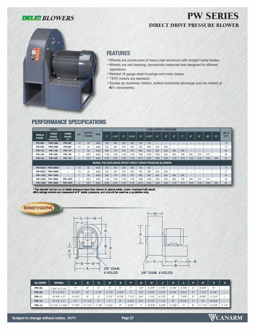
Subject to change without notice. 01/11 Page 27
BLOWER WHEEL A B C D E F G H J K L P R X V
PW-08 7 3/4" x 2 1/4" 11" 8" 3" 3" 5" 7" 1/2" 5 3/8" 4 7/8" 5 7/8" 5 7/8" 4" 6 5/8" 9" --
PW-09 9" x 2 3/4" 12 1/8" 8" 3 1/2" 3 1/2" 5 5/8" 7" 1/2" 3 3/8" 5 3/4" 6 7/8" 6 3/4" 5" 7 1/2" 9 7/8" --
PW-11 10 5/8" x 3" 14 3/4" 9" 4" 3 1/2" 6 7/8" 7 1/2" 3/4" 7 1/4" 6 1/2" 8" 7 5/8" 5" 8 5/8" 11 3/4" --
PW-12 12 1/2" x 3" 17" 11 1/4" 5" 4" 8" 9 3/4" 3/4" 8 1/4" 7 1/2" 9" 9 5/8" 7" 10" 10 5/8" --
PW-14 13 1/2" x 4 3/8" 17 5/8" 11 1/4" 7 1/8" 5 3/4" 8" 9 3/4" 1" 10 5/8" 9 5/8" 11 3/8" 11" 8" 11 1/2" 12 5/8" 7 1/4"
* Fan should not be run at static pressure less than shown in above table, motor overload will result.dBA ratings shown are measured at 0” static pressure, and should be used as a guideline only.
DIMENSIONSDIMENSIONS
OPTIONSOPTIONS
FEATURES• Wheels are constructed of heavy cast aluminum with straight radial blades.• Wheels are self cleaning, dynamically balanced and designed for efficient
operations.• Welded 16 gauge steel housings and motor bases.• TEFC motors are standard.• Comes as clockwise rotation, bottom horizontal discharge (can be rotated at 45º+ increments).
PW SERIESDIRECT DRIVE PRESSURE BLOWER
PERFORMANCE SPECIFICATIONS
SINGLE PHASE
THREEPHASE
208/230/460
THREEPHASE
575
1" 1 1/2" 2" 2 1/5" 3" 3 1/2" 4" 5" 6" 7" 8" 9" 10" 11"
PW-08S PW0-08M PW-08P 1/3 56 3600 295 265 230 200 165 125 -- -- -- -- -- -- -- -- 74
PW-09S PW0-09M PW-09P 1/3 56 3600 525 495 470 440 405 380 330 200 -- -- -- -- -- -- 77
PW-11S PW-11M PW-11P 1 56 3600 800 770 740 705 680 640 600 500 400 300 -- -- -- -- 84
PW-12S PW-12M PW-12P 3 182T 3600 1190 1160 1130 1100 1065 1030 1000 930 860 780 690 575 410 -- 90
PW-14S PW-14M PW-14P 5 182T 3600 2280 2230 2180 2130 2070 2020 1960 1840 1720 1570 1400 1240 1080 880 92
PW-08SX PW0-08MX -- 1/3 56 3600 295 265 230 200 165 125 -- -- -- -- -- -- -- -- 74
PW-09SX PW0-09MX -- 1/3 56 3600 525 495 470 440 405 380 330 200 -- -- -- -- -- -- 77
PW-11SX PW-11MX -- 1 56 3600 800 770 740 705 680 640 600 500 400 300 -- -- -- -- 84
PW-12SX PW-12MX PW-12PX 3 182T 3600 1190 1160 1130 1100 1065 1030 1000 930 860 780 690 575 410 -- 90
PW-14SX PW-14MX PW-14PX 5 182T 3600 2280 2230 2180 2130 2070 2020 1960 1840 1720 1570 1400 1240 1080 880 92
MODEL PW: EXPLOSION PROOF DIRECT DRIVE PRESSURE BLOWERS
CFM @ STATIC PRESSUREdBA @5 FT
MODEL
H.P.MOTORFRAME
RPM
D
P
V F GB
3/8” DIAM. 4 HOLES3/8” DIAM. 4 HOLES
XR
H
KLJ
C
AE E
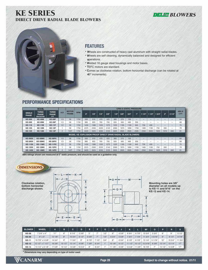
Subject to change without notice. 01/11Page 28
BLOWER WHEEL A B C D E F G H J K L M* O P R X
KE-08 7 3/4" x 4" 11" 8" 8 1/4" 5 3/8" 5" 7" 1/2" 6" 4 5/8" 6 3/4" 6 7/8" 10 3/4" 3 3/4" 8" 8" 8 1/2"
KE-09 9" x 5" 12 1/8" 8" 10 3/4" 6 1/2" 5 5/8" 7" 1/2" 6 3/4" 5 5/8" 7 3/4" 7 1/8" 11 3/4" 4 5/16" 9" 9 1/4" 9 7/8"
KE-11 10 7/8" x 5 5/8" 14 3/4" 9" 11 3/4" 8" 6 7/8" 7 1/2" 3/4" 8" 6 3/4" 9 1/8" 8 1/8" 13 1/4" 5 1/16" 10" 10 3/4" 11 3/4"
KE-12 12 1/2" x 7 1/2"" 16 3/8" 10 1/2" 13 1/4" 9 5/8" 7 3/8" 8 3/4" 1" 10 1/8" 8 1/2" 11 1/2" 10 1/2" 15 3/16" 6 3/8" 13 1/4" 13 1/4" 17"
KE-14 13 1/2" x 8 1/8" 17 5/8" 10 1/2" 14 5/8" 10 3/4" 8" 8 3/4" 1" 11 1/8" 9 3/8" 12 5/8" 11 3/8" 16 7/8" 7" 14 1/2" 14 5/8" 17"
DIMENSIONSDIMENSIONS
OPTIONSOPTIONS
FEATURES• Wheels are constructed of heavy cast aluminum with straight radial blades.• Wheels are self cleaning, dynamically balanced and designed for efficient
operations.• Welded 16 gauge steel housings and motor bases.• TEFC motors are standard.• Comes as clockwise rotation, bottom horizontal discharge (can be rotated at
45º increments).
KE SERIESDIRECT DRIVE RADIAL BLADE BLOWERS
PERFORMANCE SPECIFICATIONS
SINGLE PHASE
THREEPHASE
208/230/460
THREEPHASE
575
0" 1/8" 1/4" 3/8" 1/2" 5/8" 3/4" 1" 1 1/4" 1 1/2" 1 3/4" 2" 2 1/4"
KE-08S KE-08M KE-08P 1/3 56 1750 550 510 470 425 365 275 150 -- -- -- -- -- -- 64
KE-09S KE-09M KE-09P 1/3 56 1750 880 825 765 705 635 565 480 200 -- -- -- -- -- 69
KE-11S KE-11M KE-11P 1/2 56 1750 1430 1380 1335 1275 1225 1165 1100 945 730 430 -- -- -- 75
KE-12S KE-12M KE-12P 1 56 1750 2375 2300 2220 2140 2060 1975 1890 1700 1485 1185 750 350 -- 79
KE-14S KE-14M KE-14P 2 145T 1750 3420 3325 3230 3125 3025 2925 2820 2595 2350 2045 1620 1010 640 81
KE-08SX KE-08MX KE-08PX 1/3 56 1750 550 510 470 425 365 275 150 -- -- -- -- -- -- 64
KE-09SX KE-09MX KE-09PX 1/3 56 1750 880 825 765 705 635 565 480 200 -- -- -- -- -- 69
KE-11SX KE-11MX KE-11PX 1/2 56 1750 1430 1380 1335 1275 1225 1165 1100 945 730 430 -- -- -- 75
KE-12SX KE-12MX KE-12PX 1 56 1750 2375 2300 2220 2140 2060 1975 1890 1700 1485 1185 750 350 -- 79
KE-14SX KE-14MX KE-14PX 2 145T 1750 3420 3325 3230 3125 3025 2925 2820 2595 2350 2045 1620 1010 640 81
MODEL KE: EXPLOSION PROOF DIRECT DRIVE RADIAL BLADE BLOWERS
CFM @ STATIC PRESSUREdBA @5 FT
MODEL
H.P.MOTORFRAME
RPM
C
E EA
R
H
KLJ
P
O
D
M
DFB
G
X
dBA ratings shown are measured at 0” static pressure, and should be used as a guideline only.
* Dimensions may vary depending on type of motor used.
Mounting holes are 3/8”diameter on all models upto KE-11 and 9/16” on theKE-12 and KE-14.
Clockwise rotation,bottom horizontal discharge shown.
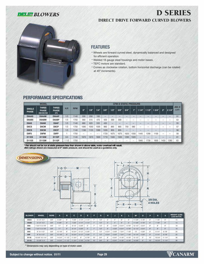
Subject to change without notice. 01/11 Page 29
BLOWER WHEEL BORE A B C D E F G H J K L M* O P R X WEIGHT (LBS)(LESS MOTOR)
D6AA 6 1/4" X 3" 5/8" 9 3/8" 8" 7 3/8" 4 1/4" 4 1/4" 7" 1/2" 5" 4" 6" 5" 11 5/8" 3 1/8" 6" 7 1/8" 9" 13
D6AB 6 1/4" X 3" 5/8" 9 3/8" 8" 7 3/8" 4 1/4" 4 1/4" 7" 1/2" 5" 4" 6" 5" 11 5/8" 3 1/8" 6" 7 1/8" 9" 13
D8A 7 3/4" X 3 7/8" 5/8" 11" 8" 8 1/4" 5 3/8" 5" 7" 1/2" 6" 4 5/8" 6 3/4" 6 7/8" 12 1/2" 3 3/4" 8" 8" 9" 18
D8C 7 3/4" X 3 7/8" 5/8" 11" 8" 8 1/4" 5 3/8" 5" 7" 1/2" 6" 4 5/8" 6 3/4" 6 7/8" 12 1/2" 3 3/4" 8" 8" 9" 18
D9C 9" X 4 1/2" 5/8" 12 1/8" 8" 10 3/4" 6 1/2" 5 5/8" 7" 1/2" 6 3/4" 5 5/8" 7 3/4" 7 1/8" 13" 4 3/8" 9" 9 1/4" 9 7/8" 25
D9F 9" X 4 1/2" 5/8" 12 1/8" 8" 10 3/4" 6 1/2" 5 5/8" 7" 1/2" 6 3/4" 5 5/8" 7 3/4" 7 1/8" 14 1/4" 4 3/8" 9" 9 1/4" 9 7/8" 25
D11E 10 5/8" X 5 1/4" 5/8" 14 3/4" 11 1/2" 11 3/4" 8" 6 7/8" 10" 3/4" 8" 6 3/4" 9 1/8" 8 1/8" 15 1/2" 5" 10" 10 3/4" 11 1/4" 36
D11G 10 5/8" X 4" 5/8" 14 3/4" 11 1/2" 11 3/4" 5 7/8" 6 7/8" 10" 3/4" 8" 6 3/4" 9 1/8" 8 1/8" 14 5/8" 4" 10" 10 3/4" 11 1/4" 36
* Fan should not be run at static pressure less than shown in above table, motor overload will result.dBA ratings shown are measured at 0” static pressure, and should be used as a guideline only.
DIMENSIONSDIMENSIONS
OPTIONSOPTIONS
FEATURES• Wheels are forward curved steel, dynamically balanced and designed
for efficient operation.• Welded 16 gauge steel housings and motor bases.• TEFC motors are standard.• Comes as clockwise rotation, bottom horizontal discharge (can be rotated
at 45º increments).
D SERIESDIRECT DRIVE FORWARD CURVED BLOWERS
PERFORMANCE SPECIFICATIONS
SINGLE PHASE
THREEPHASE
208/230/460
THREEPHASE
575
0" 1/8" 1/4" 3/8" 1/2" 5/8" 3/4" 1" 1 1/4" 1 1/2" 1 3/4" 2" 2 1/4"
D6AAS D6AAM D6AAP 1/3 1140 330 250 100 -- -- -- -- -- -- -- -- -- -- 51
D6ABS D6ABM D6ABP 1/3 1750 560 515 470 420 300 300 -- -- -- -- -- -- -- 53
D8AS D8AM D8AP 1/3 1140 680 620 535 430 -- -- -- -- -- -- -- -- -- 55
D8CS D8CM D8CP 1/3 1750 1085 1050 1005 960 865 865 750 580 -- -- -- -- -- 57
D9CS D9CM D9CP 1/3 1140 1160 1125 1090 1035 855 855 -- -- -- -- -- -- -- 56
D9FS D9FM D9FP 1 1750 -- -- -- - 1720 1675 1675 1620 1550 1445 1290 1100 -- -- 58
D11ES D11EM D11EP 3/4 1140 1970 1870 1800 1710 1500 1500 1290 1020 -- -- -- -- -- 61
D11GS D11GM D11GP 1 1/2 1750 -- -- -- -- -- -- -- -- 1840 1730 1600 1450 1280 63
CFM @ STATIC PRESSUREdBA @5 FT
MODEL
H.P. RPM
MO
P
D
X
GBF
C
E EA
R
H
KLJ
3/8 DIA. 4 HOLES
KLJ
K
O
P
MO
D
J
H
X
C
E EE
R
3/8 D4 HOL
IA.LES
BF GBF E E
AE
* Dimensions may vary depending on type of motor used.
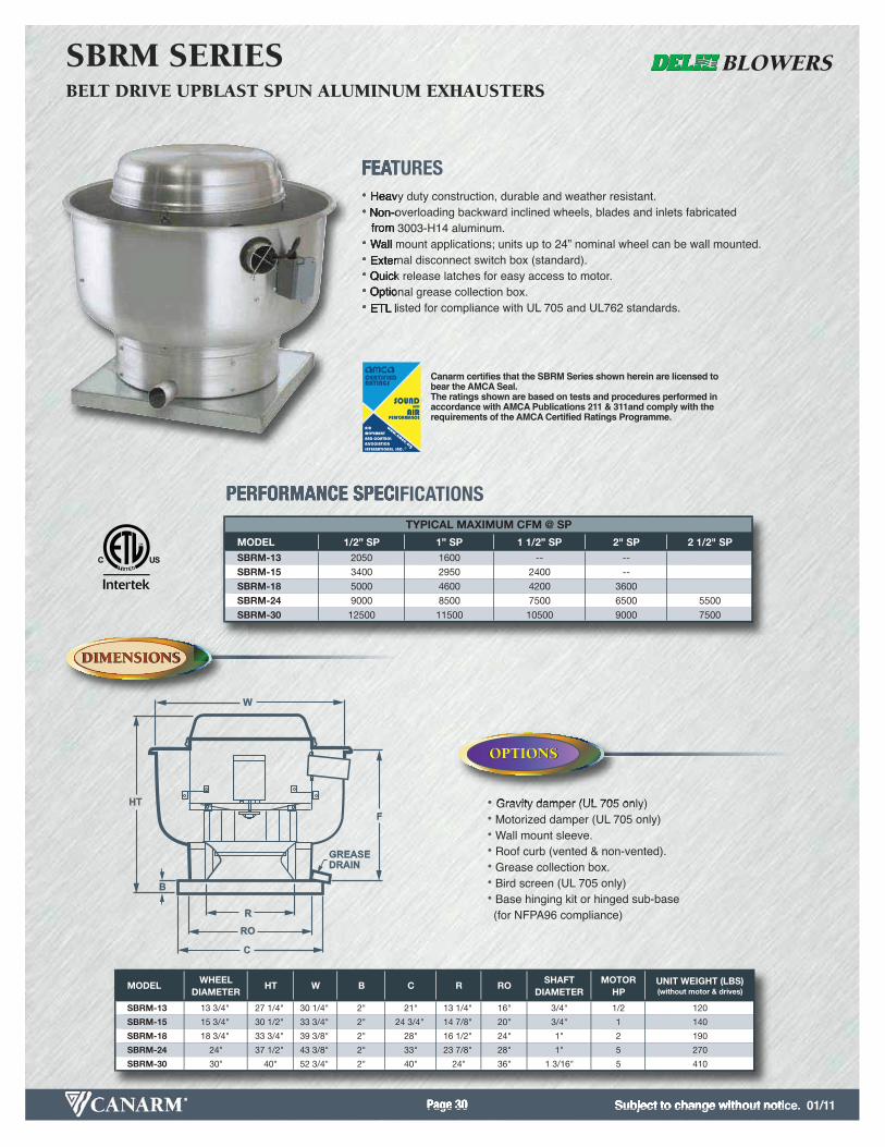
Subject to change without notice. 01/11Page 30
DIMENSIONSDIMENSIONS
OPTIONSOPTIONS
FEATURES• Heavy duty construction, durable and weather resistant.• Non-overloading backward inclined wheels, blades and inlets fabricated
from 3003-H14 aluminum.• Wall mount applications; units up to 24” nominal wheel can be wall mounted.• External disconnect switch box (standard).• Quick release latches for easy access to motor.• Optional grease collection box.• ETL listed for compliance with UL 705 and UL762 standards.
• Gravity damper (UL 705 only)• Motorized damper (UL 705 only)• Wall mount sleeve.• Roof curb (vented & non-vented).• Grease collection box.• Bird screen (UL 705 only)• Base hinging kit or hinged sub-base
(for NFPA96 compliance)
SBRM SERIESBELT DRIVE UPBLAST SPUN ALUMINUM EXHAUSTERS
PERFORMANCE SPECIFICATIONS
MODEL 1/2” SP 1” SP 1 1/2” SP 2" SP 2 1/2" SPSBRM-13 2050 1600 -- -- SBRM-15 3400 2950 2400 -- SBRM-18 5000 4600 4200 3600 SBRM-24 9000 8500 7500 6500 5500SBRM-30 12500 11500 10500 9000 7500
TYPICAL MAXIMUM CFM @ SP
MODELWHEEL
DIAMETERHT W B C R RO
SHAFTDIAMETER
MOTORHP
UNIT WEIGHT (LBS) (without motor & drives)
SBRM-13 13 3/4" 27 1/4" 30 1/4" 2" 21" 13 1/4" 16" 3/4" 1/2 120
SBRM-15 15 3/4" 30 1/2" 33 3/4" 2" 24 3/4" 14 7/8" 20" 3/4" 1 140
SBRM-18 18 3/4" 33 3/4" 39 3/8" 2" 28" 16 1/2" 24" 1" 2 190
SBRM-24 24" 37 1/2" 43 3/8" 2" 33" 23 7/8" 28" 1" 5 270
SBRM-30 30" 40" 52 3/4" 2" 40" 24" 36" 1 3/16" 5 410
Canarm certifies that the SBRM Series shown herein are licensed tobear the AMCA Seal.The ratings shown are based on tests and procedures performed inaccordance with AMCA Publications 211 & 311and comply with the requirements of the AMCA Certified Ratings Programme.
W
F
R
RO
C
B
HT
GREASE DRAIN
OPTIONSOPTIONS
OPTIONSOPTIONS
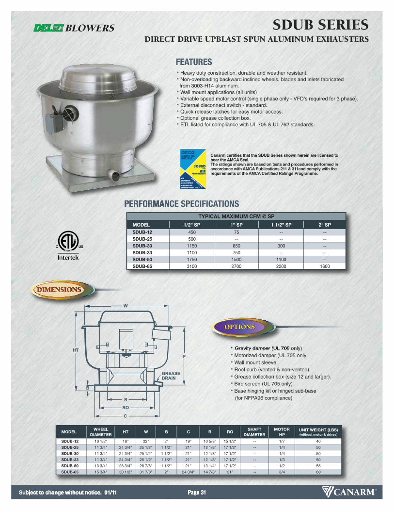
Subject to change without notice. 01/11 Page 31
Canarm certifies that the SDUB Series shown herein are licensed tobear the AMCA Seal.The ratings shown are based on tests and procedures performed inaccordance with AMCA Publications 211 & 311and comply with the requirements of the AMCA Certified Ratings Programme.
MODELWHEEL
DIAMETERHT W B C R RO
SHAFTDIAMETER
MOTORHP
UNIT WEIGHT (LBS)(without motor & drives)
SDUB-12 10 1/2" 18" 22" 2" 19" 10 5/8" 15 1/2" -- 1/7 40
SDUB-25 11 3/4" 24 3/4" 25 1/2" 1 1/2" 21" 12 1/8" 17 1/2" -- 1/4 50
SDUB-30 11 3/4" 24 3/4" 25 1/2" 1 1/2" 21" 12 1/8" 17 1/2" -- 1/4 50
SDUB-33 11 3/4" 24 3/4" 25 1/2" 1 1/2" 21" 12 1/8" 17 1/2" -- 1/3 50
SDUB-50 13 3/4" 26 3/4" 28 7/8" 1 1/2" 21" 13 1/4" 17 1/2" -- 1/2 55
SDUB-85 15 3/4" 30 1/2" 31 7/8" 2" 24 3/4" 14 7/8" 21" -- 3/4 60
W
F
R
RO
C
B
HT
GREASE DRAIN
DIMENSIONSDIMENSIONS
OPTIONSOPTIONS
FEATURES• Heavy duty construction, durable and weather resistant.• Non-overloading backward inclined wheels, blades and inlets fabricatedfrom 3003-H14 aluminum.
• Wall mount applications (all units) • Variable speed motor control (single phase only - VFDʼs required for 3 phase).• External disconnect switch - standard.• Quick release latches for easy motor access.• Optional grease collection box.• ETL listed for compliance with UL 705 & UL 762 standards.
SDUB SERIESDIRECT DRIVE UPBLAST SPUN ALUMINUM EXHAUSTERS
PERFORMANCE SPECIFICATIONS
MODEL 1/2” SP 1” SP 1 1/2” SP 2" SPSDUB-12 450 75 -- --SDUB-25 500 -- -- --SDUB-30 1150 850 300 --SDUB-33 1100 750 -- --SDUB-50 1750 1500 1100 --SDUB-85 3100 2700 2200 1600
TYPICAL MAXIMUM CFM @ SP
• Gravity damper (UL 705 only)• Motorized damper (UL 705 only• Wall mount sleeve.• Roof curb (vented & non-vented).• Grease collection box (size 12 and larger).• Bird screen (UL 705 only)• Base hinging kit or hinged sub-base
(for NFPA96 compliance)
OPTIONSOPTIONS
OPTIONSOPTIONS

Subject to change without notice. 01/11Page 32
DIMENSIONSDIMENSIONS
OPTIONSOPTIONS
FEATURES• Spun aluminum housing for dust-free, weather resistant durability.• Non-overloading backward inclined wheels, blades and inlets fabricated from 3003-H14 aluminum.
• Wall mount applications; units up to 24” nominal wheel can be wall mounted.• Standard bird screen.• Disconnect switch box.• Quick release latches for easy access to motor.
SB SERIESBELT DRIVE DOWNBLAST SPUN ALUMINUM EXHAUSTERS
PERFORMANCE SPECIFICATIONS
MODEL 1/2” SP 1” SP 1 1/2” SP 2" SP 2 1/2" SP
SB-13 2050 1600 -- -- --
SB-15 3400 2950 2400 -- --
SB-18 5000 4600 4200 3600 --
SB-24 9000 8500 7500 6500 5500
SB-30 12500 11500 10500 9000 7500
TYPICAL MAXIMUM CFM @ SP
MODELWHEEL
DIAMETERHT W B C R RO
SHAFTDIAMETER
MOTORHP
UNIT WEIGHT (LBS)(without motor & drives)
SB-13 13 3/4" 27 1/4" 29 5/8" 2" 21" 13 1/4" 16" 3/4" 1/2 105
SB-15 15 3/4" 30 5/8" 33 1/4" 2" 24 3/4" 14 7/8" 20" 3/4" 1 130
SB-18 18 3/4" 32 3/4" 38 1/4" 2" 28" 16 1/2" 24" 3/4" 2 190
SB-24 24 3/4" 37 3/4" 42 1/2" 2" 33" 23 7/8" 28" 1" 5 215
SB-30 30 3/4" 40" 52" 2" 40" 24" 36" 1 3/16" 5 380
Canarm certifies that the SB Series shown herein are licensed to bearthe AMCA Seal.The ratings shown are based on tests and procedures performed inaccordance with AMCA Publications 211 & 311and comply with the requirements of the AMCA Certified Ratings Programme.
W
RROC
B
HT
• Gravity damper.• Motorized damper.
• Wall mount sleeve.• Roof curb.
OPTIONSOPTIONS
OPTIONSOPTIONS

Subject to change without notice. 01/11 Page 33
Canarm certifies that the SD Series shown herein are licensed to bearthe AMCA Seal.The ratings shown are based on tests and procedures performed inaccordance with AMCA Publications 211 & 311and comply with the requirements of the AMCA Certified Ratings Programme.
MODELWHEEL
DIAMETERHT W B C R RO
SHAFTDIAMETER
MAX MOTORHP
UNIT WEIGHT (LBS)(without motor & drives)
SD-10 9" 14 1/2" 20 3/4" 2" 19" 8 1/8" 13" -- 1/12 30
SD-12 10 1/2" 16 1/4" 23 3/4" 2" 19" 10 5/8" 13" -- 1/7 35
SD-30 11 3/4" 19 1/8" 26 1/4" 2" 21" 12 1/8" 16" - 1/4 45
SD-33 11 3/4" 19 1/8" 26 1/4" 2" 21" 12 1/8" 16" -- 1/3 45
SD-50 13 3/4" 21 3/4" 29 3/4" 2" 21" 13 1/4" 16" -- 1/2 50
SD-85 15 3/4" 23 3/8" 33 1/4" 2" 24 3/4" 14 7/8" 20" -- 3/4 60
W
RROC
B
HT
DIMENSIONSDIMENSIONS
OPTIONSOPTIONS
FEATURES• Spun aluminum housing for dust-free, weather resistant durability
• Non-overloading backward inclined wheels,blades and inlets fabricated
from 3003-H14 aluminum.
• All sizes can be wall mounted.
• Variable Speed motor control with “off” setting
• Standard bird screen.
SD SERIESDIRECT DRIVE DOWNBLAST SPUN ALUMINUM EXHAUSTERS
PERFORMANCE SPECIFICATIONS
MODEL 1/2” SP 1” SP 1 1/2” SP 2" SP 2 1/2" SP
SD-10 300 -- -- -- --
SD-12 450 75 -- -- --
SD-30 1150 850 300 -- --
SD-33 1100 750 -- -- --
SD-50 1750 1500 1100 -- --
SD-85 3100 2700 2200 1600 --
TYPICAL MAXIMUM CFM @ SP
OPTIONSOPTIONS
OPTIONSOPTIONS • Gravity damper.• Motorized damper.
• Wall mount sleeve.• Roof curb.

Subject to change without notice. 08/09 Page 34
DIMENSIONSDIMENSIONS
OPTIONSOPTIONS
DIMENSIONSDIMENSIONS
OPTIONSOPTIONS
FEATURES• Emergency disconnect switch.• Spun aluminum housing for rust free weather resistant durability.• Propellers constructed with die formed blades riveted to a steel hub.• Can be roof or wall mounted.• Standard bird screen.• Wire conduit to provide a clear channel for electrical connections.
SDS SERIES ECONOMY MAKE UP AIR UNITS
EMUA SERIES ECONOMY MAKE UP AIR UNITS
PERFORMANCE SPECIFICATIONS
0.000 0.125 0.250 0.375 0.500
SDS-14 1/6 1100 4030 1450 1174 904 670 439
SDS-18 1/3 1100 5180 2460 2220 1980 1639 1300
STATIC PRESSURE IN INCHES W.G.MODEL HP RPM TS
FANMODEL
HT W B C ROWEIGHT (LBS)
SDS-14 12 5/8" 27 5/16" 2" 21" 16 45
SDS-18 14 3/8" 33 9/16" 2" 26" 20 67
FANMODEL
HT W B C ROWEIGHT (LBS)
EMUA-12 9 3/4" 20 5/16" 2" 19" 13 21EMUA-14 12 5/8" 27 5/16" 2" 21" 16 33
EMUA-18 14 3/8" 33 9/16" 2" 26" 20 51
PERFORMANCE SPECIFICATIONS
EMUA-12 12" WHEEL 1000
EMUA-14 14" WHEEL 1475
EMUA-18 18" WHEEL 2400
SIZEMODEL CFM AGAINST STATIC RESISTANCE
W
HT
CRO
B
W
HT
CRO
B
• Motorized backdraft damper.• Wall mount sleeve
• Hinged fan• Insulated curb
OPTIONSOPTIONS
OPTIONSOPTIONS
• Motorized backdraft damper.• Wall mount sleeve
• Hinged fan• Insulated curb
OPTIONSOPTIONS
OPTIONSOPTIONS
For use anywhere that fresh air is needed to replace exhaust air, commercial kitchens, office buildings, bakeries, laundries,factories, warehouses, foundries, locker rooms, etc.
This economy make-up air unit is a non-motorized gravity vent. It is an economical choice when a fresh air intake or pressure relief is needed.
* Approximate CFM against static resistance is based on throat area velocity of approximately 1200 fpm.
*
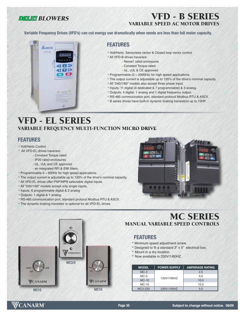
Subject to change without notice. 08/09Page 35
FEATURES• Volt/Hertz Control• All VFD-EL drives have/are:
- Constant Torque rated- IP20 rated enclosures- UL, cUL and CE approved- an integrated RFI & EMI filters.
• Programmable 0 ~ 600Hz for high speed applications.• The output current is adjustable up to 120% of the driveʼs nominal capacity.• All VFD-EL drives offer PNP/NPN selectable digital inputs.• All “240/1/60” models accept only single inputs.• Inputs: 6 programmable digital & 2 analog• Outputs: 1 digital & 1 analog. • RS-485 communication port, standard protocol Modbus RTU & ASCII.• The dynamic braking transistor is optional for all VFD-EL drives.
VFD - B SERIESVARIABLE SPEED AC MOTOR DRIVES
MC SERIESMANUAL VARIABLE SPEED CONTROLS
VFD - EL SERIESVARIABLE FREQUENCY MULTI-FUNCTION MICRO DRIVE
Variable Frequency Drives (VFD’s) can cut energy use dramatically when needs are less than full motor capacity.
MODEL POWER SUPPLY AMPERAGE RATING
MC-3 2.5MC-5 5.0MC-10 10.0MC-15 15.0
MC5-230 230V/1/60HZ 5.0
120V/1/60HZ
• Minimum speed adjustment screw.• Designed to fit a standard 3” x 5” electrical box.• Mount in a dry location.• Now available in 230V/1/60HZ.
MC10MC15
MC3/5
FEATURES
FEATURES• Volt/Hertz, Sensorless vector & Closed loop vector control• All VFD-B drives have/are:
- Nema1 rated enclosures- Constant Torque rated- UL, cUL & CE approved
• Programmable (0 ~ 2000Hz) for high speed applications.• The output current is adjustable up to 120% of the driveʼs nominal capacity.• All “240/1/60” models also accept three phase input.• Inputs: 11 digital (4 dedicated & 7 programmable) & 3 analog.• Outputs: 4 digital, 1 analog and 1 digital frequency output. • RS-485 communication port, standard protocol Modbus RTU & ASCII.• B series drives have built-in dynamic braking transistors up to 15HP.
Subject to change without notice. 08/09 Page 36
FACILITIES
CORPORATE OFFICE / MANUFACTURING FACILITY2157 Parkedale AvenueBrockville, ON K6V 5V6 CanadaTel: (613) 342-5424 Fax: 1-800-263-4598
CANARM WAREHOUSE100 Strowger Blvd.
Brockville, ON K6V 5J9 Canada
USA WAREHOUSE808 Commerce Park Drive
Ogdensburg, New York 13669USA
Tel: 1-800-267-4427Fax: 1-800-263-4598
MANAGEMENT SUPPORT
JAMES A. COOPERPresident Tel: (613) 342-5424 (X 1307)Cell: (613) 498-8540Email: [email protected]
DOUG MATTHEWSVice-President - HVAC & Agri Products
Tel: (613) 342-5424 (X 1325)Cell: (613) 213-0781
Email: [email protected]
BOB CLARKEVice-President - US SalesTel: (716) 870-1917Fax: (716) 633-8929Email: [email protected]
DON BARKLEYKey Accounts Manager - Canada
Tel: (613) 342-5424 (X 1335)Cell: (613) 340-4581
Email: [email protected]
TIM SUTTON, CSPKey Accounts Manager - Canada
Tel: (613) 342-5424 (X 1341)Cell: (613) 349-5687
Email: [email protected]
STEVE MARSHTechnical Sales RepresentativeTel: (613) 342-5424 (X 1321)USA Tel: 1-800-267-4427Fax: 1-800-263-4598Email: [email protected]
DIANA LAWSONWarranty Tel: (613) 342-5424 (X 1353)USA Tel: 1-800-267-4427Fax: 1-800-263-4598Email: [email protected]
WWW.CANARM.COM WWW.DELHI-INDUSTRIES.COM
CINDY WILKINSCustomer Service Rep
Canadian AccountsTel: (613) 342-5424 (X 1324)
USA Tel: 1-800-267-4427Fax: 1-800-263-4598
Email: [email protected]
NICOLE WILLIAMSCustomer Service RepUS AccountsTel: (613) 342-5424 (X 1327)USA Tel: 1-800-267-4427Fax: 1-800-263-4598Email: [email protected]
NANCY PAULCustomer Service Rep
Special AccountsTel: (613) 342-5424 (X 1339)
USA Tel: 1-800-267-4427Fax: 1-800-263-4598
Email: [email protected]
CONTACTS
FIELD SUPPORT
CUSTOMER SERVICE
TECHNICAL SUPPORT
PRODUCT WARRANTY
WEB SITES
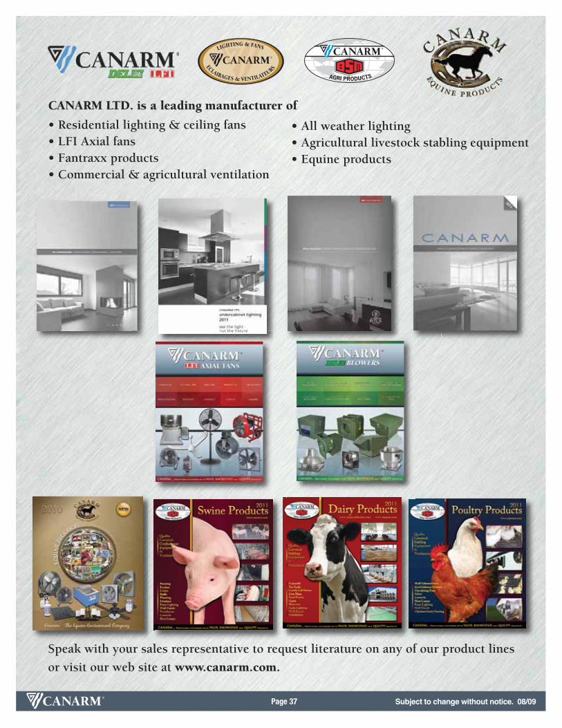
Subject to change without notice. 08/09Page 37
CANARM LTD. is a leading manufacturer of
• Residential lighting & ceiling fans• LFI Axial fans • Fantraxx products• Commercial & agricultural ventilation
• All weather lighting • Agricultural livestock stabling equipment• Equine products
Speak with your sales representative to request literature on any of our product lines
or visit our web site at www.canarm.com.
CORPORATE OFFICE / MANUFACTURING FACILITY2157 Parkedale AvenueBrockville, ON K6V 5V6 CanadaTel: (613) 342-5424 Fax: 1-800-263-4598
CANARM WAREHOUSE100 Strowger Blvd.
Brockville, ON K6V 5J9 Canada
USA WAREHOUSE808 Commerce Park Drive
Ogdensburg, New York 13669USA
Tel: 1-800-267-4427Fax: 1-800-263-4598
FEBRUARY, 2011
Specifications subject to change without notice.Due to limitations with the printing process the products illustrated are representative only of the actual products.
Printed in Canada
CATALOGUE - DELHI-DIST-FE-11
WWW.CANARM.COM [email protected] WWW.DELHI-INDUSTRIES.COM