DELAWARE, OH 43015 740.362.0251 Command Module Timing
18
ELECTRIMOTION INC. 1484 DALE FORD RD. DELAWARE, OH 43015 740.362.0251 Command Module Timing Controller Lenco Start (2 Shift inputs) w/Auto shifter, Timing Monitor and Rev-Limiter Connections Inputs : 2 pin plug (red-black) wires 9-16 volt input Purple Wire (Rpm output) To Tach Start wires: (Green) starts channels 1-8 (Blue – Blk) starts channels 9-16 (Yellow – Blk) starts channels 17-24 Timer starts when start (Green Wire) has 12v removed. Transbrake wire. 2 Shift Inputs: Grounding Blue and Yellow wires starts shift timers. (Blk wire is Gnd) The shift inputs are ground to start. Safety Box Inputs Safety Box Outputs RF Timer Channels 1- 15 Timer Channels 16- 24 Auto Shifter Timing Control Red= Input Power Black= Ground F/B Tether B B B B B Ana Fuel Chute IGN B B B B B B 21 R 20 19 18 17 R B 24 23 22 B 16 B R 12 13 14 15 6 R 5 4 3 2 11 R B 10 9 8 7 B 1 B R B G1 G2 G3 G4 B UP SHIFT B G1 G2 G3 G4 B DOWN SHIFT GND GND GND GND ANA Out Ign Kill Ign Out GND Trig in Boost In Ign Out TACH OUT 12v Mounting: 10-32 screws—2.500” by2.000” Warning Do not use screws longer than 3/8” or damage to unit may occur. Overall Dims: 6.0 ” *4.5” 2.75”
Transcript of DELAWARE, OH 43015 740.362.0251 Command Module Timing

ELECTRIMOTION INC. 1484 DALE FORD RD. DELAWARE, OH 43015 740.362.0251
Command Module Timing Controller Lenco Start (2 Shift inputs)
w/Auto shifter, Timing Monitor and Rev-Limiter
Connections Inputs : 2 pin plug (red-black) wires 9-16 volt input Purple Wire (Rpm output) To Tach Start wires: (Green) starts channels 1-8 (Blue – Blk) starts channels 9-16 (Yellow – Blk) starts channels 17-24
Timer starts when start (Green Wire) has 12v removed. Transbrake wire. 2 Shift Inputs: Grounding Blue and Yellow wires starts shift timers. (Blk wire is Gnd) The shift inputs are ground to start.
Safety Box Inputs Safety Box Outputs RF
Timer Channels 1- 15 Timer Channels 16- 24 Auto Shifter Timing Control
Red= Input Power Black= Ground
F/B Tether
B B B B B
Ana Fuel Chute IGN B B B B B B
21 R 20 19 18 17
R B 24 23 22 B 16 B R
12 13 14 15 6 R 5 4 3 2
11 R B 10 9 8 7 B 1 B R
B G1 G2 G3 G4 B
UP SHIFT
B G1 G2 G3 G4 B DOWNSHIFT
GND GND GND GND
ANA Out
Ign Kill
Ign Out GND
Trig in
Boost
In
Ign Out
TACH OUT 12v
Mounting: 10-32 screws—2.500” by2.000”
Warning Do not use screws longer than 3/8” or damage to unit may occur.
Overall Dims: 6.0 ” *4.5” 2.75”

Overview:
The Electrimotion Command Module is a modular control system designed to control high performance racing vehicles. Timer: The Command Module is made up of 24 timed outputs w/RPM and Pressure inputs that can be configured to trigger an output channel. Timing Controller: The Command Module also has a programmable timing controller that allows the users to build an ignition retard curve up to -30.0° with 16 points and an Idle retard setting. The Timing Controller also has 2 shift inputs that will allow the user to pull out timing at the instant you shift. The Timing Controller also has an analog (Boost) retard input that can be used to retard timing based on an 0-5v signal. New for Ver 4.0 is a built-in rev limiter and the ability to shift the entire curve up or down. Timing Monitor: The Command Module Timing Monitor uses the RPM signal generated by the Command Module and a TDC signal supplied by a TDC pickup, to calculate the ignition timing in Degrees before TDC. This timing value is provided to the user as a 0-5v signal that can be monitored by any data acquisition system that can accept an 0-5v analog input. The Timing Monitor does not have a menu entry on the Command Module. Autoshifter: The Command Module Autoshifter allows the user to shift the transmission (up to a 4 speed) based on RPM, locked out by time. Data entry can be done on the keypad or via the pc with the included Command Module software. The Command Module has an SD memory card to facilitate transferring data to and from the pc. Safety Box: The Command Module Ver 4.0 has the EM Safety Box built into the unit. The Tether, RF and Fire bottle/Driver Button inputs can be monitored in real time to assist in wiring and troubleshooting. The Safety Box also has an analog output that can be monitored by your computer to tell you exactly when and what triggered the safety system.

Timer: The 24 Timer channels have the following programmable features.
On times including “On Now” mode, which allows a channel to be on before the throttle is hit.
Off mode, which can be a time or another channel. In off channel
mode, a timer channel will turn off when another channel turns on; this is useful in turning on a sequence of outputs one at a time.
RPM Mode, which allows a channel to turn on at a specific RPM. The
on and off times still apply to RPM channels.
PSI Mode, which allows a channel to turn on at a specific pressure.
The on and off times still apply to PSI channels. Timing Controller:
The timing controller has the ability to build a timing retard curve with an idle retard and 16 time/degree points. The timing controller has 2 shift inputs that have a ramp time and a retard degree number. The shift retard feature allows you to pull timing out at the moment you shift. The timing will be ramped back in, in the ramp time that you enter. Rev limiter is built-in, also a 2-step rev limit is available. Using the Shift Curve menu, you can raise or lower the entire curve.
Timing Monitor:
The Timing Monitor produces a 0-5v analog output that represents the ignition timing. This 0-5v signal can be monitored by any data acquisition system that accepts a 0-5v analog input.
Autoshifter:
Each shift, 1-2, 2-3, and 3-4 has its own Time and RPM value. The Autoshifter will set a 12v output upon each shift that can be used to turn on an air valve to shift the transmission. The time value is an inhibit time that prevents the gear change until the time has elapsed and the RPM is met. Time and RPM values can be edited via the keypad or by PC software.
If the RPM for a specific gear change is not met before the next gear change inhibit time, that specific gear output will turn on when the next gear change inhibit time is met. This is a safety feature.
The Autoshifter also has a manual up and down shift input which can be wired to a toggle switch in the car to allow manual shifting during the burnout.

Button Functions:
Command Module Alky Ver 4.00
Home Button: Returns unit to starting screen.
Menu up and Down: Used to select mode of operation. Timer, Air Regulator, Auto Shift, Timing Control.
Up and Down: Used to select channel and also used to change data values
Function Buttons: Used to enter the edit modes. F1: Used to enter on time edit mode. F2: Used to enter the mode, Timer or RPM. F3: Used to enter off time/channel edit mode.
Enter Button: Used to enter timer mode. Also, used to save an edited value.

Module Operation:
Main Menu:
By Pressing the Menu up button, you can cycle through the installed modules, which can include up to the following modules. Press the enter button to enter the selected menu item.
Main Menu items
24 Ch. Timer Timing Controller Auto Shifter Safety Box Battery Voltage (Displays current battery voltage) Transfer File (Menu to send or receive file to SDcard)
Menu up and Down Buttons
24 Ch. Timer
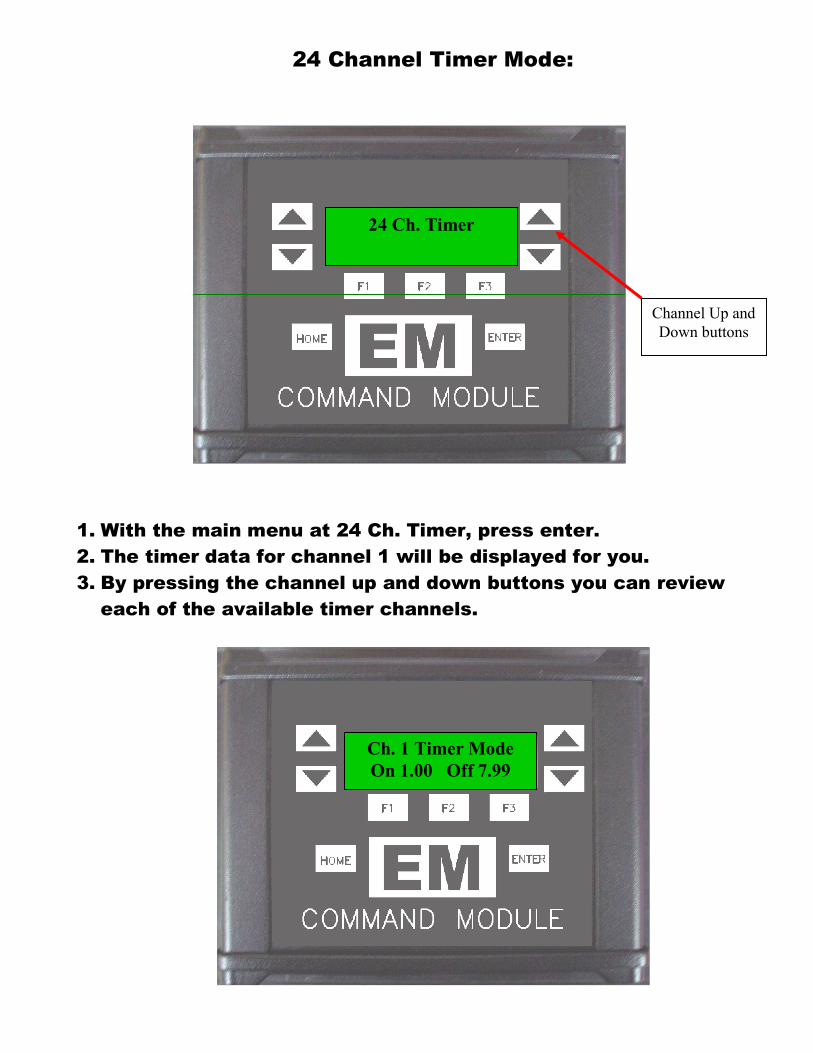
24 Channel Timer Mode:
1. With the main menu at 24 Ch. Timer, press enter. 2. The timer data for channel 1 will be displayed for you. 3. By pressing the channel up and down buttons you can review
each of the available timer channels.
24 Ch. Timer
Channel Up and Down buttons
Ch. 1 Timer Mode On 1.00 Off 7.99

Timer On Time Edit Mode:
1. To edit an on time, press the F1 button, the screen will change to a blinking on time.
2. Now the channel up and down buttons will allow you to change the on time.
3. After pressing F1 you will be able to edit the second's value, to change the tenths digit, press F2 while in edit mode. To edit the hundredths digit, press the F3 button while in edit mode.
4. To select the “On Now” mode, set the on time to 0.00 and then press the channel down button one more time.
5. To save the edited value, press enter and the screen will stop blinking.
Timer Off Time Edit Mode:
1. To edit an off time press the F3 button, the screen will change to a blinking off time.
2. Now the channel up and down buttons will allow you to change the off time.
3. After pressing F3 you will be able to edit the second's value, to change the tenths digit, press F2 while in edit mode. To edit the hundredths digit, press the F3 button while in edit mode.
4. To save the edited value, press enter and the screen will stop blinking.
Timer Off Channel Edit Mode:
1. To edit an off channel, press the F3 button, the screen will change to a blinking off time.
2. Press the channel up and down buttons until the off-time value changes to a Channel number i.e. CH. 5.
3. To save the edited value, press enter and the screen will stop blinking.

Timer Channel Mode Edit:
1. To change a timer channel to RPM or PSI mode, press the Home button to return to the home screen.
2. Press the up Menu button, the display will show 24 Ch. Timer. 3. Press enter, the display will show the on and off times for
channel 1. 4. Press the F2 button and the display will begin blinking
Ch. 1 Timer mode, to change to RPM or PSI mode press the Channel up button. Press the enter button to save the mode change.
5. Press the channel up button again and the RPM or PSI value for channel 1 is displayed.
6. Press F2 to enter the RPM or PSI edit mode. The display will begin blinking.
7. For RPM using the F1(Thousands), F2(Hundreds), F3(Tens) buttons you can edit the RPM value for channel 1. Press enter to save the RPM value.
8. For PSI using the F1(Hundreds), F2(Tens), F1(Ones), buttons you can edit the RPM value for channel 1. Press enter to save the RPM value.
9. The on and off times of an RPM channel continue to work as normal. I.e. if you have an RPM channel set to 8000 RPM and the on and off times set to (On time 1.00) and (Off time 7.99). The output will turn on only if the RPM is over 8000 RPM and the time is between 1.00 and 7.99 sec from the respective start signal.
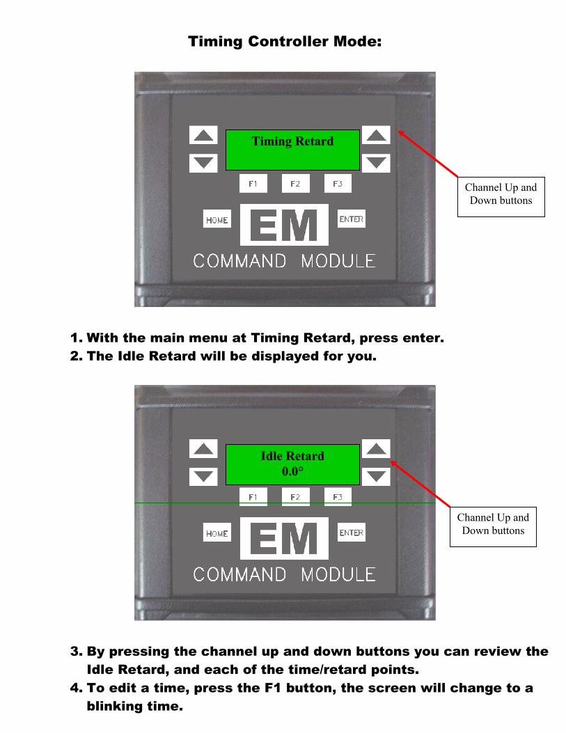
Timing Controller Mode:
1. With the main menu at Timing Retard, press enter. 2. The Idle Retard will be displayed for you.
3. By pressing the channel up and down buttons you can review the Idle Retard, and each of the time/retard points.
4. To edit a time, press the F1 button, the screen will change to a blinking time.
Timing Retard
Idle Retard 0.0°
Channel Up and Down buttons
Channel Up and Down buttons

5. Now the channel up and down buttons will allow you to change the seconds’ digit of the time.
6. If you would like to change the tenths digit, press F2. If you would like to change the hundredths digit, press the F3 button.
7. To save the new time, press enter and the screen will stop blinking.
Retard Ch. 1 1.00 Sec 5.0°
Retard Ch. 1 1.00 Sec
Channel Up and Down buttons
Channel Up and Down buttons

1. To edit a retard value, press the F2 button, the screen will change to a blinking retard value.
2. Now the channel up and down buttons will allow you to change the retard value.
3. After pressing F2 you will be able to edit the tens digit of the retard value, to change the ones digit, press F3 while in edit mode.
4. To save the edited value, press enter and the screen will stop blinking.
Retard Ch.1 5.0° Retard

Shift Retard
1. To edit a shift retard value, press the channel up button, until the screen changes to the 1-2 or 2-3 shift retard screen
2. Using the F1 and F2 buttons you can change the time or retard values.
3. Now the channel up and down buttons will allow you to change the retard or time value.
4. To save the edited value, press enter and the screen will stop blinking.
Shift retard:
1 – 2 Shift 1.00 Sec 5.0°

Boost retard
1. To edit the Boost Retard value, press the channel up button, until the screen changes to the Boost Retard screen
2. Press the F2 button to enter the Boost Retard edit mode. 3. Now press F1 to edit the Tens digit, Press F2 to edit the ones
digit or press F3 to edit the Tenths digit. 4. Channel up and down buttons allow you to change the Boost
Retard value. 5. To save the edited value, press enter and the screen will stop
blinking.
Boost retard:
Boost Retard 30.0
Channel Up and Down buttons

Rev Limit
1. To edit the High Rev Limit value, press the channel up button, until the screen changes to the High Rev Limit screen
2. Press the F2 button to enter the High Rev Limit edit mode. 3. Now press F1 to edit the Thousands digit, Press F2 to edit the
hundreds digit or press F3 to edit the Tens digit. 4. Channel up and down buttons allow you to change the Rev limit
value. 5. To save the edited value, press enter and the screen will stop
blinking. 6. Launch Rev Limit and Launch Retard values are entered the
same way. The Launch Rev limit and Launch retard values are active when the Transbrake is applied.
High rev limit:
High Rev Limit 13000 RPM
Channel Up and Down buttons

Auto Shift
Auto shift Inhibit Time Edit Mode: 1. To edit an Inhibit time press the F1 button, the screen will
change to a blinking Inhibit time. 2. Now the channel up and down buttons will allow you to change
the on time. 3. After pressing F1 you will be able to edit the second's value, to
change the tenths digit, press F2 while in edit mode. To edit the hundredths digit, press the F3 button while in edit mode.
4. To save the edited value, press enter and the screen will stop blinking.
Auto shift RPM Edit Mode:
1. To edit an Auto shift RPM, press the F3 button, the screen will change to a blinking RPM value.
2. Now the channel up and down buttons will allow you to change the RPM.
3. After pressing F1 you will be able to edit the Thousands value, to change the Hundreds digit, press F2 while in edit mode. To edit the tens digit, press the F3 button while in edit mode.
4. To save the edited value, press enter and the screen will stop blinking.
1 -2 Shift On 1.00 RPM 8500

Safety Box:
Monitoring Safety Box Inputs: 1. To monitor the inputs to the Safety Box, press the menu button
up until you see “Safety Box”, then press enter. 2. The display will show “SB Input Status” the second line will
show the state of the Tether input “Tether Normal”. 3. By pressing the Channel Up button you will see each of the
Safety Box inputs in real time. This can be used to verify the inputs or troubleshoot the safety system
Safety Box
SB Input Status Tether Normal

File Transfer Mode:
1. Included with the Command Module is a software program that you can install on your PC. Editing of all Command Module settings can be done on the PC and saved to an SDCARD for transfer to the unit. The program is located on the SDCARD in a folder named PC_Software.
2. With the main menu at Transfer Menu, you can transfer the module data to the SDCARD or transfer data from the SDCARD.
3. To transfer the module data to the SDCARD press F1. 4. The Display will show “File Transfer Successful” when completed. A
new file called Carfile.ema will now be saved to the SDCARD. 5. To transfer the settings from the SDCARD to the module press F3. 6. The module will display the first EMA file on the card on the second
line of the display. By pressing the up and down channel buttons you can scroll through the list of up to 20 EMA files on the SDCARD. Once you see the file that you want to load, press enter.
7. The Display will show “All”, this means that all the values in the file will be transferred to the CM. By pressing the up and down channel buttons you can select either a specific module or all modules for transferring. Press enter to initiate the transfer.
8. The Display will show “File Transfer Successful” when completed. (Takes about 10-15 seconds).
Transfer File To SD From SD

General Warnings: IT IS THE RESPONSIBILITY OF THE PERSON INSTALLING ANY CONTROL SYSTEM COMPONENT OR
KIT TO DETERMINE THE SUITABILITY OF THE COMPONENT OR KIT FOR THAT PARTICULAR APPLICATION. IF YOU ARE NOT SURE HOW TO SAFELY USE THIS COMPONENT OR KIT, YOU SHOULD
NOT INSTALL OR USE IT. DO NOT ASSUME ANYTHING. IMPROPERLY INSTALLED OR MAINTAINED CONTROL SYSTEMS ARE DANGEROUS. IF YOU ARE NOT SURE, GET HELP OR RETURN THE
PRODUCT. YOU MAY OBTAIN ADDITIONAL INFORMATION AND TECHNICAL SUPPORT BY CALLING ELECTRIMOTION AT (740) 362-0251, OR VISIT OUR WEB SITE AT WWW.ELECTRIMOTION.COM. USE OF ELECTRIMOTION TECHNICAL SUPPORT DOES NOT GUARANTEE PROPER INSTALLATION. YOU, OR THE PERSON WHO DOES THE INSTALLATION, MUST KNOW HOW TO PROPERLY USE THIS PRODUCT. IT IS NOT POSSIBLE OVER THE PHONE TO UNDERSTAND OR FORESEE ALL THE ISSUES THAT MIGHT
ARISE IN YOUR INSTALLATION. LIABILITY ON DEFECTIVE MERCHANDISE OR MERCHANDISE NOT CONFORMING TO MANUFACTURER’S SPECIFICATIONS IS LIMITED TO THE REPAIR OR REPLACEMENT
OF THE DEFECTIVE ITEM. RACING EQUIPMENT MUST BE MAINTAINED AND SHOULD BE CHECKED REGULARLY FOR FATIGUE, DAMAGE, AND WEAR. DO NOT OPERATE ANY VEHICLE ON UNTESTED
CONTROL SYSTEMS!