Degree Programme in Construction Engineering BECONU07B3 …
82
Lightweight purlins stiffened with polyurethane foam Bachelor’s thesis Degree Programme in Construction Engineering BECONU07B3 22.11.2011 Sujan Shakya
Transcript of Degree Programme in Construction Engineering BECONU07B3 …
Lightweight purlins stiffened with polyurethane foam
Bachelor’s thesis
Degree Programme in Construction Engineering
BECONU07B3 22.11.2011
Sujan Shakya

BACHELOR’S THESIS
Degree programme in Construction Engineering
Visamäentie 35 B
13100 HÄMEENLINNA
Title Lightweight steel purlins stiffened with polyurethane foam
Author Sujan Shakya
Supervised by Lassi Martikainen
Approved on _____._____.20_____
Approved by

ABSTRACT
VISAMÄKI
Degree programme in Construction Engineering
Author Sujan Shakya Year 2011
Subject of Bachelor’s thesis Lightweight steel purlins stiffened with polyu-
rethane foam
ABSTRACT
The objective of this thesis was to implement new ways to stiffen the cold-
formed steel (CFS) profiles in steel purlin systems. The use of polyure-
thane foam as stiffeners in purlin system is an innovative approach and is
worth testing. This thesis was commissioned by Sheet Metal Center
(SMC) and tests were conducted in SMC test hall from March 2011 till
August 2011.
The aim of this thesis was to find an innovative method of stiffening cold-
formed steel purlins against various buckling modes. Polyurethane boards
(PU-boards) can be used as longitudinal stiffeners in the cold-formed C-
profiles/purlins which will reinforce the profiles against buckling. The
combination of PU-board of high stiffness-low strength and lightweight
purlin of high strength-low stiffness were used to conduct the test to obtain
beams with high strength and high stiffness.
The metal sheets used for the C-profile manufacture were S280+Z275 of
thickness 0.5mm and S350+Z275 of thickness 1.0mm. In total, 20 tests
were carried out which included two different cross-sections from each
sheet-steel types. A four point bending setup was used to conduct the
bending stiffness test. The average tangent bending stiffness of unstiffened
profiles for S280+Z275 and S350+Z275 were 324,64 kNm2 and 829,23
kNm2 respectively. When profile webs of each sheet-steel material type
were stiffened by polyurethane foam, values of tangent bending stiffness
increased by 3% to 4% respectively. Similarly for web and flange stiff-
ened profiles, the values leaped up to 11% and 9% respectively. Using
PU-board as flange stiffeners were able to yield approximately an addi-
tional 10% of the bending stiffness compared to unstiffened beam. This
means that the flanges are very critical members regarding the bending
stiffness of the C-profile and stiffening flanges against buckling modes
can be a very effective way to increase the bending stiffness of CFS-
profiles.
Keywords cold-formed steel, C-purlin, polyurethane foam, bending stiffness, stiffen-
ers.
Pages 51 p. + appendices 27 p.

CONTENTS
1 INTRODUCTION ....................................................................................................... 1
2 COLD-FORMED STEEL PURLINS .......................................................................... 2
2.1 Introduction ......................................................................................................... 2
2.2 Stiffeners ........................................................................................................... 10
2.3 Stiffening by using polyurethane boards ........................................................... 12
3 EXPERIMENTAL PROGRAM ................................................................................ 17
3.1 Introduction ....................................................................................................... 17
3.2 Sheet-steel test materials ................................................................................... 18
3.3 Test specimen design and test specimen manufacture ...................................... 22
3.4 Test arrangement ............................................................................................... 25
3.4.1 Test rig design ....................................................................................... 25
3.4.2 Test loading ........................................................................................... 26
3.4.3 Test setup ............................................................................................... 26
4 TEST RESULTS, EVALUATION AND COMPARISON OF TEST DATA .......... 30
4.1 Failure modes .................................................................................................... 30
4.1.1 Combined flange and web buckling ...................................................... 30
4.1.2 Lateral buckling ..................................................................................... 31
4.1.3 Local flange buckling ............................................................................ 31
4.1.4 Shear failure of polyurethane boards ..................................................... 32
4.2 Analysis of the test results ................................................................................. 33
5 CONCLUSIONS ....................................................................................................... 48
SOURCES ...................................................................................................................... 50
Appendix 1 TEST GRAPHS AND FIGURES OF S280 TEST SERIES
Appendix 2 TEST GRAPHS AND FIGURES OF S350 TEST SERIES
Appendix 3 INFORMATION ON THE GLUE USED IN THE TEST SPECIMEN
MANUFATURE
Appendix 4 CALCULATION OF THE BENDING STIFFNESS FOR S350+Z275 C-
PROFILE

Lightweight steel purlins stiffened with polyurethane foam
1
1 INTRODUCTION
This thesis project was commissioned by Sheet Metal Center (SMC).
SMC is a research and development unit under the administration of
HAMK University of Applied Sciences that works both as an educational
and training institute as well as an enterprise. It was established in 1998 to
provide various weathering tests and structural analysis on various struc-
tures as their service to the customers. Later, SMC started working as a
hybrid of a business point and an educational institute. SMC also provides
work placement and thesis topics in various fields of construction engi-
neering to many graduating students of HAMK. (HAMK 2011.)
The aim of this thesis is to analyze the performance of PU-boards used in
stiffening C-profiles to increase the bending stiffness of the stiffened pro-
files. The specimens created will be tested in the test hall of SMC and the
test results are compared in order to obtain a productive conclusion.
The use of cold-formed steel products is gaining popularity in construction
industry and it is very critical for any industry to succeed economically
and environmentally. To meet such demands, factors that affect industrial
economy and the surrounding environment like technical issues, design
criteria of load-bearing sheets and products, technical findings and inven-
tions must be kept going on so as to update any changes that is on the
goodwill of the industry. Innovations of grooves and bents in cold-formed
profiles have helped the profiles to become more efficient as the grooves
and bends work as they increase load bearing capacities of the profiles and
sheets. Similarly, use of polyurethane boards as stiffeners is an innovative
approach and is worth testing. This is a new approach towards the meth-
ods of stiffening CFS profiles by other materials rather than only grooves
and bends that are/could be made in the profile cross-section.
This thesis will be focusing on a different method of stiffening cold-
formed steel purlins against various buckling modes. Polyurethane boards
can be used as longitudinal stiffeners in the cold-formed C-profiles/purlins
which will reinforce the profiles against buckling. The PU-boards have
contrasting characteristics compared to C-profile as C-profile high
strength and low stiffness whereas PU-board is relatively stiffer but has
low material strength. The combination of these contrasting materials both
of which are used widely in construction industry should yield favorable
results of C-profiles with high strength as well as high stiffness.
Calculations regarding the determination of bending resistance of the un-
stiffened C-profile were completed according to Eurocode 3. Eurocode 3
provides us an approach to design a cold-formed C-profile cross-section
on the basis of “effective width method” where the large extent com-
pressed parts of the member element are regarded ineffective and are
omitted from design consideration and effective parts are considered to
undergo uniform bending stresses.

Lightweight steel purlins stiffened with polyurethane foam
2
2 COLD-FORMED STEEL PURLINS
2.1 Introduction
The use of cold-formed steel (CFS) as structural members was introduced
in the mid nineteenth century in the United States and Great Britain. How-
ever, many limitations were set when using CFS as structural members in
building constructions until the introduction of the very first specification
for the design of cold-formed steel structural members. This specification
was published for the very first time by American Iron and Steel Institute
(AISI 1946). (Young, n.d. 119-120.)
After the official publication of the code, the use of CFS structural mem-
bers has increased dramatically over the years. From domestic houses to
large city complexes, the use of CFS structural members of different
forms, different shapes and sizes have played significant role in building
industry in many different ways. Despite of having high deflection to
loading ratio due to it being a slenderness member, cold-formed steel pro-
files have stood up for their good strength- to-weight ratio. The manufac-
turing process of fabricating CFS profiles, namely brake-pressing and roll
forming of steel sheets makes it possible to produce CFS profiles of vari-
ous cross-sectional shapes which encourage creative designs in building
construction. (The Steel Framing Alliance n.d, 2.) Also, cold-forming
method increases the yield strength of the material due to strain hardening.
“New products in thin steel sheets, combined with improved plating and
insulating materials, make steel an interesting option with an increasing
number of applications in modern construction.” (European Lightweight
Steel-Frame Construction 2005, 2).
Moreover, its flexibility in various shapes and cross-sections has made
cold-formed profiles friendlier in many applications in construction indus-
try. In addition, nestable cross-section designs enable compact packaging
and shipping. Some of the advantages of CFS purlins over other building
materials are as follows:
Cost effective
Shorter and predictable construction schedule
Highest strength-to-weight ratio of any building material
100% recyclable
Noncombustible- does not burn or contribute as fire load during the
spread of fire
Inorganic- will not rot, warp, split, crack or creep
Dimensionally stable- does not expand or contract with moisture con-
tent
Consistent material quality- produced in strict accordance with stand-
ard requirements
High strength results in safer structures, less maintenance and slower
aging of the structure etc.
Suitable for automated mass-production
Lightweight steel purlins stiffened with polyurethane foam
3
Due to the above mentioned advantages, CFS framing system has been
developed under the influence of “open” construction system like in tim-
ber construction and it has started replacing other building materials al-
ready. This system has a lot to offer as the system relies on methods and
techniques based on smart principles and flexible assemblies and not on a
particular project or any given situations. Hence, this system is called
“third-generation system”. (European Light-Weight Steel Construction, 6)
Cold-formed steel framing system refers to a structural framing system
comprising cold-formed steel members like beams, columns, joists, studs
etc. Places where the climate is very humid or places prone to termite or
woodworm infestations, lightweight steel structures prove to be very ef-
fective in those regions. Wooden studs, wooden beams and columns,
wooden truss in timber buildings are substituted by CFS studs, profiles,
CFS purlins and CFS trussing system in CFS framing system. In this way,
cost of maintenance for CFS framed building decreases making this “third
generation” the very first choice of structural designers. (European Light-
Weight Steel Construction, 6)
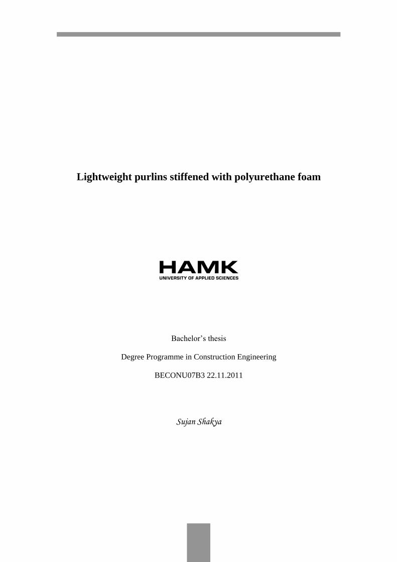
Load-bearing panels and composite panels do not only carry the normal
load that is acting vertically downwards on them but also act as dia-
phragms to resist forces in their own planes given that they are intercon-
nected to each other and to the connecting members correctly.
Figure 1 Percentage of self-supporting steel framing used in multi-story residential
buildings (European Lightweight Steel-Framed Construction 2005, 2)
Figure 1 represents the data corresponding to the use of self-supporting
steel framing systems in multi-story residential buildings in different
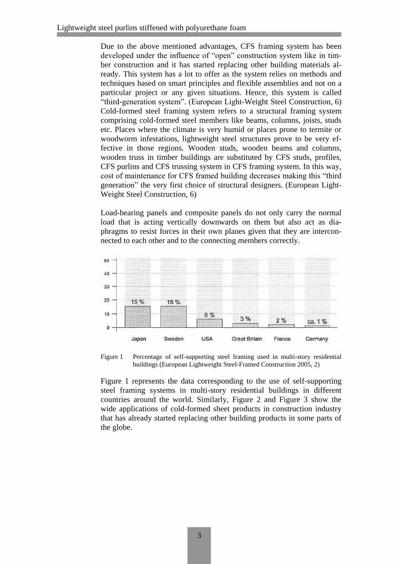
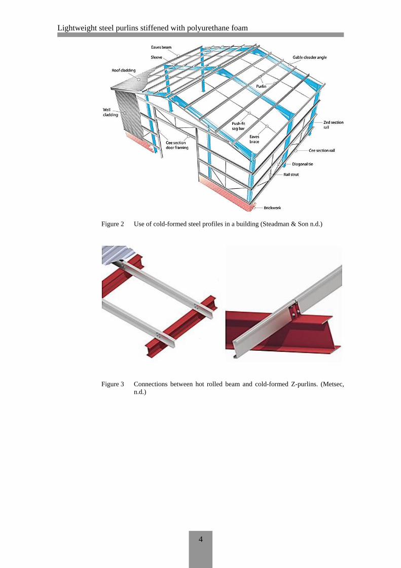
countries around the world. Similarly, Figure 2 and Figure 3 show the
wide applications of cold-formed sheet products in construction industry
that has already started replacing other building products in some parts of
the globe.
Lightweight steel purlins stiffened with polyurethane foam
4
Figure 2 Use of cold-formed steel profiles in a building (Steadman & Son n.d.)
Figure 3 Connections between hot rolled beam and cold-formed Z-purlins. (Metsec,
n.d.)

Lightweight steel purlins stiffened with polyurethane foam
5
Figure 4 Use of CFS purlin system in floor construction and roof construction respec-
tively (Kingspan multibeam 2007, 5)
In Figure 4, we can see different applications of C-profiles in a steel
framed building. C-profiles used in the roof as a primary or secondary
beam will experience forces from self-weight of the roof structure, snow
load and wind load on the roofing sheet. C-profiles will generate a large
amount of deflection as the span of the profile increases because it has a
very low stiffness ratio. For serviceability limit design, a structural mem-
ber must acquire as less deflection as possible. Similarly, in case of floor
construction, in order to decrease deflection at the mid span of the floor, it
requires more profiles to carry imposed loads with less deflection. As the
number of purlins increases or an extra member is introduced in the sys-
tem, the cost of the whole construction increases. So, a new design or a
system is required that can withstand design values of imposed loads with
low deflections and this project is an attempt to implement that system.
There are many cross-section shapes and sizes in CFS purlins that have
been developed in recent years. However, some of the very typical cross-
sections commonly used in building industry are C shaped purlins, Z or
Sigma purlins and Hat profiles etc. These profiles are often used as load
bearing members in roofs, floors, walls etc. as well as structural members
like columns, beams, joists etc. Typical forms of CFS cross-sections are
shown in Figure 5.

Lightweight steel purlins stiffened with polyurethane foam
6
Figure 5 Typical forms of section for cold-formed members (EN 1993-1-3:2006, 8)
Similarly, Figure 6 illustrates different types of cross-sections for cold-
formed members and sheets. Profile members shown in Figure 6 includes
very typical cross-sections e.g. C, hat and all profile sheets. However,
complicated cross-sections shown in Figure 6 are manufactured as desired
by the customer or required by design plan. Due to the alterations and/or
repetitions of grooves and bends in a profile cross-section, grooves and
bends provide much greater strength compared to the typical profile cross-
sections.
Lightweight steel purlins stiffened with polyurethane foam
7
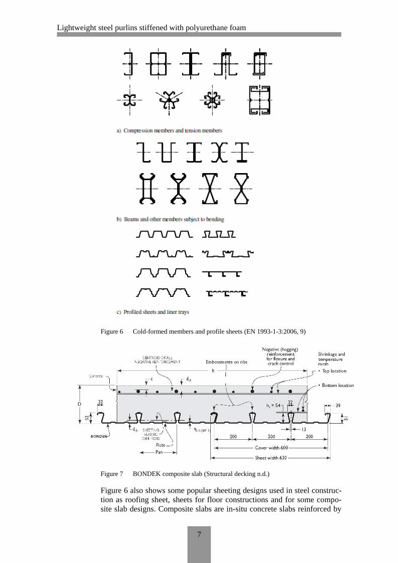
Figure 6 Cold-formed members and profile sheets (EN 1993-1-3:2006, 9)
Figure 7 BONDEK composite slab (Structural decking n.d.)
Figure 6 also shows some popular sheeting designs used in steel construc-
tion as roofing sheet, sheets for floor constructions and for some compo-
site slab designs. Composite slabs are in-situ concrete slabs reinforced by

Lightweight steel purlins stiffened with polyurethane foam
8
sheeting of different cross-sections. An example of composite slab is
shown in Figure 7.
Cold-formed profiles and sheets, due to their slender character, will expe-
rience different buckling modes considering the loadings and support con-
ditions. Some of the buckling phenomena that may occur in CFS elements
are local buckling, distortional buckling, overall buckling, lateral distor-
tional buckling, flexural torsional buckling etc. Among them, global buck-
ling is a very common buckling in every loading case and is inevitable to
prevent. When a cold-formed C-profile experiences flexural or axial load,
it experiences local and distortional buckling along with overall buckling
of the beam considering a laterally restrained support condition.
Figure 8 a) Examples of elastic critical stress for various buckling modes as function
of half-wavelength and examples of buckling modes. b) Examples of elastic
buckling resistance as function of member length (EN 1993-1-3:2006, 25)
Lightweight steel purlins stiffened with polyurethane foam
9
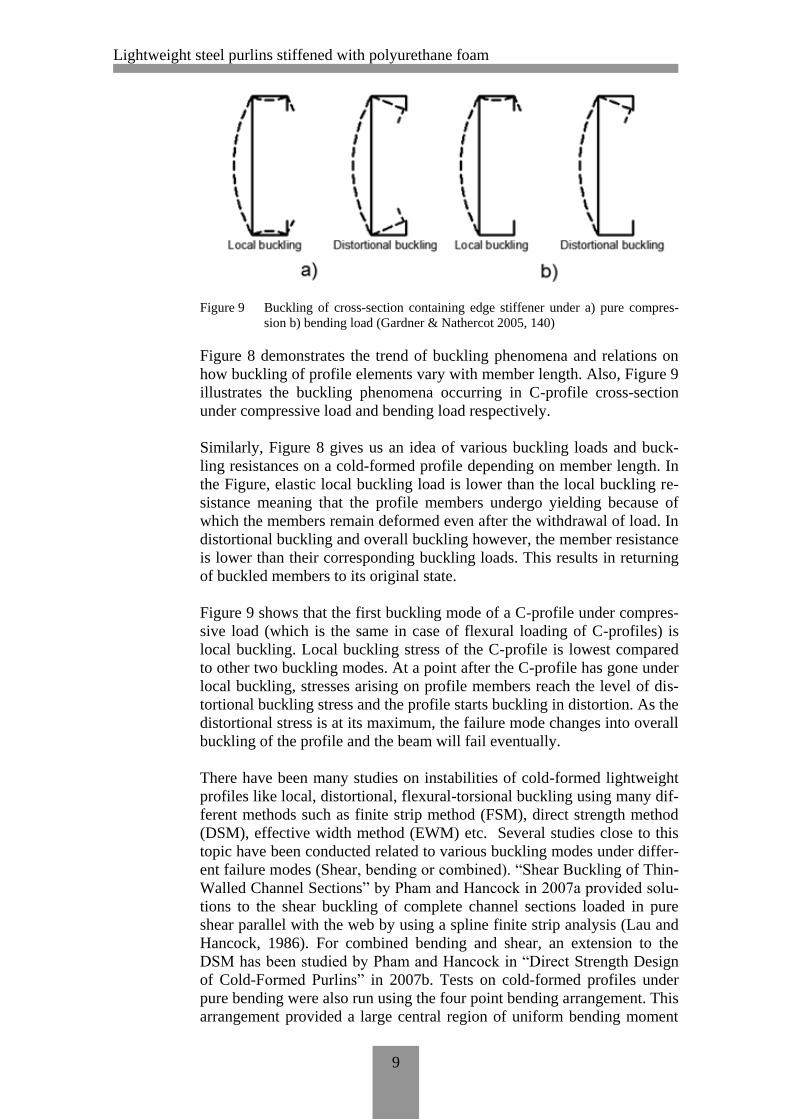
Figure 9 Buckling of cross-section containing edge stiffener under a) pure compres-
sion b) bending load (Gardner & Nathercot 2005, 140)
Figure 8 demonstrates the trend of buckling phenomena and relations on
how buckling of profile elements vary with member length. Also, Figure 9
illustrates the buckling phenomena occurring in C-profile cross-section
under compressive load and bending load respectively.
Similarly, Figure 8 gives us an idea of various buckling loads and buck-
ling resistances on a cold-formed profile depending on member length. In
the Figure, elastic local buckling load is lower than the local buckling re-
sistance meaning that the profile members undergo yielding because of
which the members remain deformed even after the withdrawal of load. In
distortional buckling and overall buckling however, the member resistance
is lower than their corresponding buckling loads. This results in returning
of buckled members to its original state.
Figure 9 shows that the first buckling mode of a C-profile under compres-
sive load (which is the same in case of flexural loading of C-profiles) is
local buckling. Local buckling stress of the C-profile is lowest compared
to other two buckling modes. At a point after the C-profile has gone under
local buckling, stresses arising on profile members reach the level of dis-
tortional buckling stress and the profile starts buckling in distortion. As the
distortional stress is at its maximum, the failure mode changes into overall
buckling of the profile and the beam will fail eventually.
There have been many studies on instabilities of cold-formed lightweight
profiles like local, distortional, flexural-torsional buckling using many dif-
ferent methods such as finite strip method (FSM), direct strength method
(DSM), effective width method (EWM) etc. Several studies close to this
topic have been conducted related to various buckling modes under differ-
ent failure modes (Shear, bending or combined). “Shear Buckling of Thin-
Walled Channel Sections” by Pham and Hancock in 2007a provided solu-
tions to the shear buckling of complete channel sections loaded in pure
shear parallel with the web by using a spline finite strip analysis (Lau and
Hancock, 1986). For combined bending and shear, an extension to the
DSM has been studied by Pham and Hancock in “Direct Strength Design
of Cold-Formed Purlins” in 2007b. Tests on cold-formed profiles under
pure bending were also run using the four point bending arrangement. This
arrangement provided a large central region of uniform bending moment
Lightweight steel purlins stiffened with polyurethane foam
10
and no shear force in order to make bending stresses as the only predomi-
nant stress in the mid span of the test specimen. This method is very effec-
tive as the region contains only bending stress and no shear stress, making
the test results on bending actions very precise. So the same test arrange-
ment will be used in this thesis.
2.2 Stiffeners
In Figure 5 and Figure 7, we can see different types of cross-sectional
shapes of profiles, sheets being flat surfaced containing simple cross-
sections as well as sheets containing various shapes with grooves and
bends in their cross-sections. Grooves and bends made in CFS profiles and
load bearing sheets act like stiffeners making the members much stiffer,
resisting buckling failures thereby increasing the overall resistance of the
members. Typically, stiffeners are the steel angle or plate or combination
of plates attached to a slender beam in order to prevent its buckling nature
by increasing its stiffness. Stiffeners can be longitudinal or transverse de-
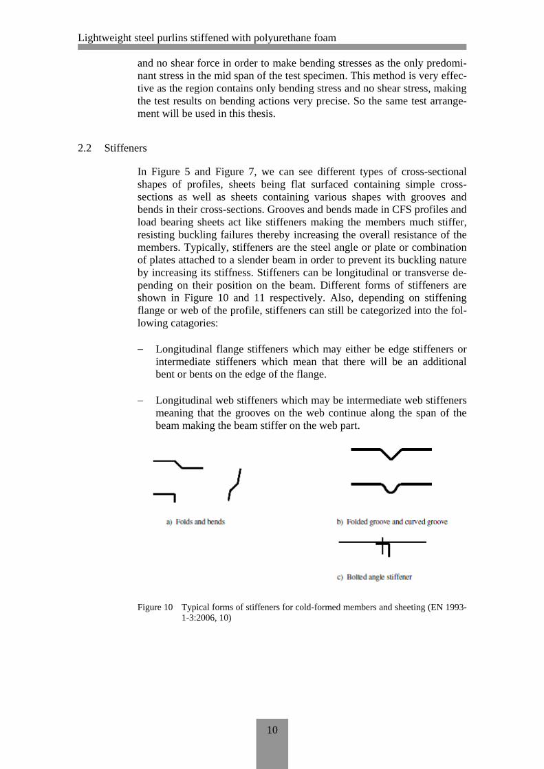
pending on their position on the beam. Different forms of stiffeners are
shown in Figure 10 and 11 respectively. Also, depending on stiffening
flange or web of the profile, stiffeners can still be categorized into the fol-
lowing catagories:
Longitudinal flange stiffeners which may either be edge stiffeners or
intermediate stiffeners which mean that there will be an additional
bent or bents on the edge of the flange.
Longitudinal web stiffeners which may be intermediate web stiffeners
meaning that the grooves on the web continue along the span of the
beam making the beam stiffer on the web part.
Figure 10 Typical forms of stiffeners for cold-formed members and sheeting (EN 1993-
1-3:2006, 10)

Lightweight steel purlins stiffened with polyurethane foam
11
Figure 11 Typical a) edge stiffeners; b) intermediate longitudinal stiffeners (EN 1993-
1-3:2006, 10)
On a simply supported beam or a column, mid span of the beam is usually
the critical place when it comes to buckling loads and bending stresses.
Members of the CFS profile like web and flanges hold similar case. If the
nodes between webs and flanges of a cold-formed steel profile are consid-
ered as fixed supports, the middle part of each compressed member expe-
riences critical buckling stress under various buckling conditions. Under
the loading, compressed members start to experience various failure phe-
nomena like buckling, twisting, torsion etc. So stiffeners in CFS profiles
and sheets are placed in places that are prone to buckling. Stiffeners are
mostly present in the middle of profile member especially in a flange apart
from the case of edge stiffeners whereas the position of stiffeners in web
largely depend on the loading cases (axial or flexural) and depending
which side of web the buckling phenomenon takes place.
Stiffeners illustrated in Figure 10 and Figure 11 respectively, work in two
typical ways.
1) Grooves and bents used as intermediate stiffeners in webs and
flanges increase the material presence in the stiffened region. This,
in most of the cases, increases the overall moment of inertia of the
cross-section thereby increasing the overall resistance of the profile
or sheet.
2) Grooves and bents used as intermediate stiffener in webs and
flanges increase the stiffness of the profile/sheet as these stiffeners
are assumed to contain linear or rotational springs acting at the
centroid of the effective stiffener section. These imaginary linear
or rotational springs provide their stiffness to the member which
results in increase of stiffness of the profile. Spring stiffness can be
of many different kinds depending on nature of loading, boundary
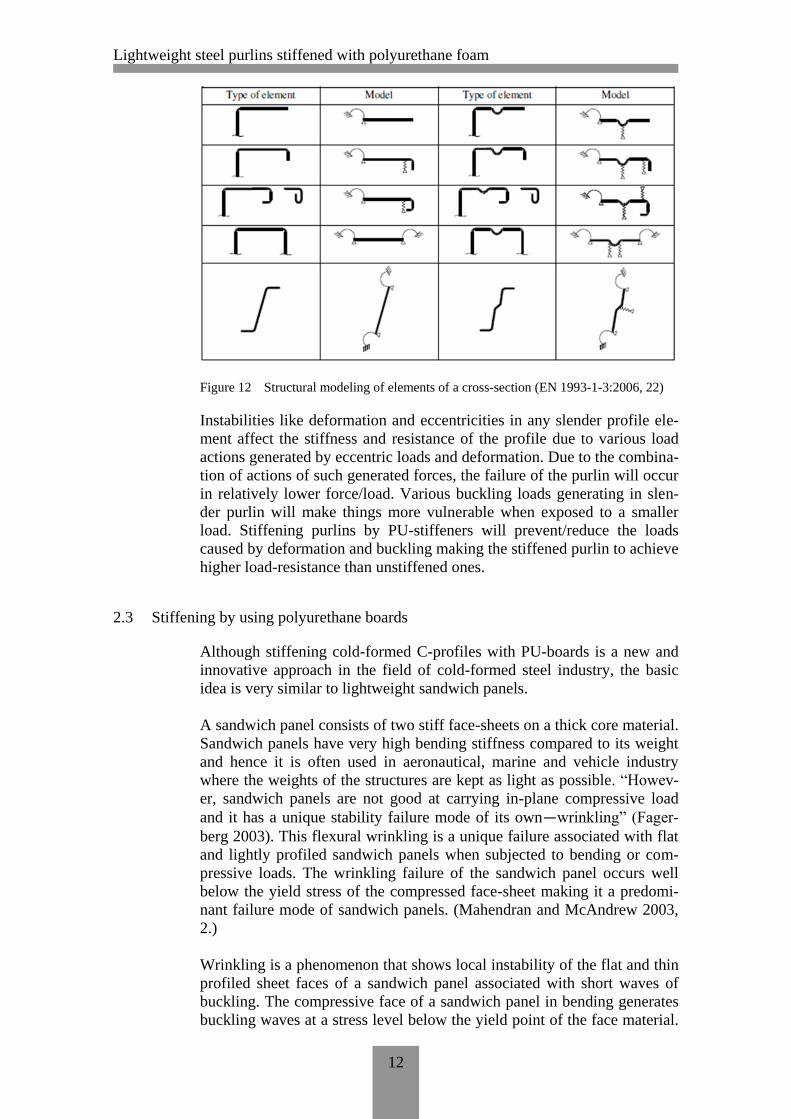
conditions, profile cross-section etc. Figure 12 illustrates the mod-
eling of elements of a cross-section with or without stiffeners.
Lightweight steel purlins stiffened with polyurethane foam
12
Figure 12 Structural modeling of elements of a cross-section (EN 1993-1-3:2006, 22)
Instabilities like deformation and eccentricities in any slender profile ele-
ment affect the stiffness and resistance of the profile due to various load
actions generated by eccentric loads and deformation. Due to the combina-
tion of actions of such generated forces, the failure of the purlin will occur
in relatively lower force/load. Various buckling loads generating in slen-
der purlin will make things more vulnerable when exposed to a smaller
load. Stiffening purlins by PU-stiffeners will prevent/reduce the loads
caused by deformation and buckling making the stiffened purlin to achieve
higher load-resistance than unstiffened ones.
2.3 Stiffening by using polyurethane boards
Although stiffening cold-formed C-profiles with PU-boards is a new and
innovative approach in the field of cold-formed steel industry, the basic
idea is very similar to lightweight sandwich panels.
A sandwich panel consists of two stiff face-sheets on a thick core material.
Sandwich panels have very high bending stiffness compared to its weight
and hence it is often used in aeronautical, marine and vehicle industry
where the weights of the structures are kept as light as possible. “Howev-
er, sandwich panels are not good at carrying in-plane compressive load
and it has a unique stability failure mode of its own—wrinkling” (Fager-
berg 2003). This flexural wrinkling is a unique failure associated with flat
and lightly profiled sandwich panels when subjected to bending or com-
pressive loads. The wrinkling failure of the sandwich panel occurs well
below the yield stress of the compressed face-sheet making it a predomi-
nant failure mode of sandwich panels. (Mahendran and McAndrew 2003,
2.)
Wrinkling is a phenomenon that shows local instability of the flat and thin
profiled sheet faces of a sandwich panel associated with short waves of
buckling. The compressive face of a sandwich panel in bending generates
buckling waves at a stress level below the yield point of the face material.

Lightweight steel purlins stiffened with polyurethane foam
13
As the amplitude of the wave increases gradually, a wrinkle is formed at
the location of greatest bending moment and/or imperfections in the panel.
“Wrinkling phenomenon is controlled by the vertical supports provided by
the core to the face-sheet and the shear stiffness of the core material. This
support provided by the core governs the wrinkling wavelength and the
buckling load.” (Staal, Horrigan, Mallison & Jayaraman n.d.)
As the slender face-sheet of the sandwich panel tends to buckle in relative
low flexural load or low compressive load, core material which is glued
chemically, will prevent the buckling phenomena of the face-sheet by
providing its own stiffness to the slender sheet. The wave created by the
load will either bend in towards the core material or bend away from the
core material. If the curve tends to bend away from the core material, ad-
hesive force provided by high performance glue will prevent it buckling
away from the core material. Likewise, if the wave is bending towards the
core material, continuous support of the core material will reinforce the
face-sheet by providing its stiffness to the sheet hence preventing it buck-
ling inwards. As the loading stresses get higher, core material starts to
crush and glue gives up and eventually the panel will fail in local buckling
or wrinkling of the face-sheet. This phenomenon is illustrated in Figure
13.
Figure 13 (a) Sandwich panel cross-section; (b) wrinkling of compressed face in sand-
wich panel side view
Likewise, our cold-formed C-profiles stiffened by PU-boards hold a simi-
lar case when considering the mechanism of PU-board in C-profile. When
the unstiffened C-profile is loaded in flexural load, ripples of small wave-
length start appearing in compressed zones of the profile due to the gener-
ated elastic local buckling stresses. As the loading in the profile increases,

Lightweight steel purlins stiffened with polyurethane foam
14
stresses in and around the compressed zone increase dramatically as the
profile will fail under high buckling stress. On the other hand, PU-
stiffened C-profiles are able to withstand higher buckling stresses in the
compressive zone of the profile. This is because PU-stiffeners/foam of the
compressed zone under compressive stress will start working effectively
against the buckling stresses as they provide their continuous stiffness to
the corresponding compressed member. The PU-stiffeners for flanges and
webs under compression start to work as continuous supports for the com-
pressive members which will control the role of buckling in the member
elements. A structural model of PU-stiffened C-profiles explaining the
working mechanism of PU-foam is shown in Figure 14.
Figure 14 Structural model of PU-stiffened C-profiles illustrating bending stiffness pro-
vided by continuous support of PU-foam to the plane parts of the profile
which are (a) compressive flange (b) whole web member (c) wide flange.
Blue lines representing C-profiles and dotted yellow shade PU-boards.
However, wrinkling phenomenon of compressed elements in case of C-
profile is not as severe in a sandwich panel. In case of sandwich panel, the
width-to-thickness ratio of the compressed face is very high and has more
tendency to buckle in smaller load. Unlike sandwich panel, compressed
elements of C-profile have relatively smaller width meaning relatively
stiffer profile-member. Moreover, wrinkling is a predominant failure mode
in sandwich panel loaded in flexure whereas in case of C-profile, there are
several other failure modes that can take place than local buckling of com-
pressed member elements depending upon various loading conditions.
Local buckling of compression elements is not the only major failure
mode that occurs in the profile during the loading. Web crippling of cold-
formed steel member is also a very common failure mode in cold-formed
steel profiles especially in case of CFS profiles with longer web member.
Usually, cold-formed steel flexural members have high web element/large
web slenderness ratios so webs of those profiles are likely to cripple due to
high local load intensity. Figure 15 gives us an idea of web crippling in
cold-formed steel flexural members. (Cold-Formed Steel Design for the
Students 2008, 6.)

Lightweight steel purlins stiffened with polyurethane foam
15
Figure 15 (a) Web crippling failure modes for single hat section and I-section profile
respectively(b) web crippling failure prevented by the use of PU-foam as
stiffeners
“Web crippling failure mode is rather a complicated phenomenon and it is
affected by the following factors.
non-uniform stress distribution under the applied load and adjacent
portions of the web
elastic and inelastic stability of the web element
local yielding in the immediate region of load application
bending produced by eccentric load or reaction when it is applied on
the bearing flange at a distance beyond the curved transition of the
web
initial out-of-plane imperfection of plate elements
various edge restraints provided by beam flanges and interaction be-
tween flange and web elements etc.” (Cold-Formed Steel Design for
the Students 2008, 6.)
Even though web crippling is one of the critical failure phenomena in
higher CFS flexural member profile; such phenomenon can be prevent-
ed/reduced by introducing PU-foam in the profiles. As shown in figure 15,
PU-foam fastened with the profile will provide a continuous stiff support

Lightweight steel purlins stiffened with polyurethane foam
16
to the buckling web elements of the profile by giving its own compressive
stiffness to the web element. In figure 15(b), a single hat profile has been
stiffened by putting PU-foam in the concave part of the hat profile. As PU-
foam fills the inside gap of the profile, webs of the hat profile are prevent-
ed from buckling as PU-foam provides its compressive stiffness to the
web member of the hat profile. Similarly, in case of two fastened C-
profiles, the web gets a continuous support from PU-foam against buck-
ling. PU-foam stiffening each side of the C-profile prevents web crippling
of the C-profile web member.

Lightweight steel purlins stiffened with polyurethane foam
17
3 EXPERIMENTAL PROGRAM
3.1 Introduction
The purpose of conducting this experimental test is to implement a new al-
ternative to stiffen the cold-formed steel profiles which, in this project,
will be polyurethane boards as stiffeners. As mentioned earlier, all the
theoretical analysis of determining the maximum load-bearing capacity of
the test specimens rely on the requirements and standards set by Eurocode
3: design of steel structures which promotes effective width method analy-
sis in a CFS purlin system. Also, this research, if successful, would
strengthen the role of stiffeners of a different material property than the
purlin itself. So, the bending stiffness tests were run on stiffened and un-
stiffened profiles which contained several combinations of PU-boards and
C-profile. In order to accomplish the bending stiffness test on C-profiles,
the test specimens were first designed and then manufactured.
Design of the test specimens include different alternatives of using differ-
ent shapes of PU-boards, attach them via chemical bonding and use them
as stiffeners to the C-profiles. In Figure 16, it is shown that there are alto-
gether four different alternatives of using PU-boards for C-profile stiffen-
ing.
Manufacture of the test specimens consisted of a careful production of de-
signed test specimens in the laboratory under a senior supervision.
Figure 16 Various combination sketches of test series to analyze bending stiffness of
the beam. Shaded parts describe PU-boards.
In Figure 16, the first four combinations A, B, C and D respectively have
identical C-profile sectional properties. However, combination E consists
of a different CFS profile, a slender profile consisting of a long flange and
a short lip can be seen.
Combination A of the Figure 16 will be made by fastening two C-profiles
mechanically. Combination B shows two C-purlins glued together on a
PU-board. In combination B, profile webs are stiffened. Combination C
consists of C-profiles glued together on PU-board of the same profile
height as well as PU-board glued on concave part of each profile. In com-
bination C, profile webs are stiffened and flanges are partially stiffened.
Combination D shows C-profiles stiffened by PU-boards of the same pro-
file height in between the profile and inside each profile. In combination
D, profile webs are stiffened on both sides whereas flanges are stiffened,

Lightweight steel purlins stiffened with polyurethane foam
18
too. Combination E consists of PU-board as wide as flange of the profile
glued in between two C-purlins without lips.
Combinations illustrated in Figure 16 will be our proposed test series. By
analyzing the cross-sections in Figure 16, it is easy to predict that the fail-
ure mode and buckling phenomena will be similar in combinations A, B,
C and D respectively. However, Combination E will have a different ac-
tion against the loading and it will provide us a different failure mode as
the profile cross-section doesn’t consist of a steel web but PU-boards to
transfer flexural load along the beam.
3.2 Sheet-steel test materials
All the sheet-steel materials and other materials that help prepare test
specimens are very commonly used in building industry and are recom-
mended by designers and builders in Finland. The sheet-steel materials se-
lected for the tests in this project are shown in detail in Table 1.
Table 1 illustrates the type of steel grade used in the manufacture of the
cold-formed steel profiles and the standard that it is taken from. It also de-
scribes the type of coating in each sheet-steel material and the thickness of
each sheet of the steel sheet. Also, the basic yield strength fyb and ultimate
tensile strength fu are mentioned in Table 1. Most importantly, Table 1 de-
scribes the material type of the steel where S280 and S350 stand for struc-
tural steel of yield strengths 280 N/mm2 and 350 N/mm
2 and Z275 means
that the steel has been coated by 275g of hot dip zinc per sq. meter of the
sheet. Moreover, the steel type we used, S280+Z275, has an additional
epoxy coating as an ultimate surface coating. (EN 1993-1-3, 14, 2006)
Table 1 Material properties of the CFS-sheets
Type of steel Standard Type of
Materials
Type of external
layer
Thickness (mm)
fyb (N/mm²)
fu
(N/mm²)
Continuous hot dip zinc coated carbon steel sheet of structural quality
EN 10326
S280+Z275 Epoxy coated
0.5mm 280 360
S350+Z275 Zinc coated 1.0mm 350 420
From the sheet-steel materials mentioned above, the designed C-profiles
were manufactured in the SMC premises. The sheets were initially cut into
lengths of the perimeter of each profile. The cut sheets were bent several
times by using a press brake in order to achieve the desired cross-sections
without losing their material strength. The cross-sections chosen to con-
duct this test are illustrated in Figure 17.

Lightweight steel purlins stiffened with polyurethane foam
19
Figure 17 Cold-formed cross-sections (a) Lipped C-profile, (b) wide flange profile
In Figure 17, two typical CFS profile cross-sections used in the test are il-
lustrated. In the Figure, h stands for the height of the profile, b for breadth,
c for lip width and t for thickness, where thickness and breadth of the
cross-section in this case have two variables.
Cross-sectional properties and length details of the profiles used in the
tests are shown in Table 2.
Table 2 Cross-sectional properties and length details
Name of the profile
Type of material
Thickness t (mm)
Height h (mm)
Breadth b (mm)
Lip width c (mm)
Length L (mm)
Cross-section pe-rimeter P
(mm)
Lipped C-profile
S280+Z275 0.5 200 50 20 2000 340
S350+Z275 1.0 200 50 20 2500 340
Wide flange profile
S280+Z275 0.5 - 150 20 2000 190
S350+Z275 1.0 - 150 20 2500 190
In Table 2, the cross-section geometry of all profile cross-sections has
been described. Also, the profile length of each cross-section type has been
mentioned in the table. Furthermore, cross-section perimeter has been cal-
culated which is the exact amount of sheet length to be cut to create a sin-
gle CFS profile.
Figure 18 CFS profile with dimensions of C-profile and wide flange profile

Lightweight steel purlins stiffened with polyurethane foam
20
Apart from the steel sheets that are used in the production of test speci-
mens, several other materials were also used i.e. polyurethane boards and
chemical adhesive named “Macroplast UK 8150”. Moreover, other sup-
plementary materials were used to conduct the tests i.e. LVL boards cut in-
to different sizes and SD3 and SD6 fasteners.
LVL strips and smaller PU-strips were used only during the test proce-
dure. In combination A, LVL strips were fixed at each end of the profile in
order to support the test beam against lateral buckling. Also, LVL strips
were placed in first 2 combinations and PU-strips in combination C right
under the loading points to distribute the load into the tensile region of the
test beam. LVL strips and PU-strips did not contribute in the test results in
any way as those materials were placed for the test to run according to
plan. If these test beams are to be mass-produced, the LVL strips and PU-
strips can be omitted from the manufacture process.
Figure 16 showed us the initial sketches of the combinations that were de-
signed to be manufactured. However, during the manufacturing process, it
was learnt that the manufacture of combination D in Figure 16 was impos-
sible considering the fact that stiffeners should be able to reinforce the el-
ements of the profile against various buckling modes which was difficult
to achieve in that case. Also, the distribution of PU-board around the neu-
tral axis of the beam doesn’t contribute in beam stiffening. So, a new set
of combinations were declared which is illustrated in Figure 19.
Figure 19 New set of combination for test specimen manufacture
As for PU-boards, they had to be cut in many panels of different sizes ac-
cording to the combinations shown in Figure 19. A typical PU-board
cross-section size used during the test specimen manufacture was
50mmx200mm. On the other hand, combination C required 50mmx80mm
extra pieces as flange stiffeners. Correct sizes and their total number of
boards are mentioned in Table 3. The same table was used during the cut-
ting process of PU-boards.
The PU-boards used during the test specimen manufacture were cut from a
bigger PU-panel of dimensions 1200mm x 2600mm x 50mm. The density
of the PU-foam is approximately 40 kg/m3. The thermal conductivity of
the PU-foam is 0.027 W/mK. Information on the method of creating test
series names is described in Table 4.

Lightweight steel purlins stiffened with polyurethane foam
21
Table 3 Polyurethane board dimensions and requirements
Series name Combination
type No. of tests
No. of 50x200
PU-board
No. of 50x80 PU-
board
Total PU-sizes (Pcs)
Length of PU-board
(mm) 50x200 50x80
S280_0,5_A_Series1 A 3 0 0 0 0
2000
S280_0,5_B_Series2 B 3 1 0 3 0
2000
S280_0,5_C_Series3 C 3 1 4 3 12
2000
S280_0,5_D_Series4 D 3 3 0 9 0
2000
S350_1,0_A_Series5 A 2 0 0 0 0
2500
S350_1,0_B_Series6 B 2 1 0 2 0
2500
S350_1,0_C_Series7 C 2 1 4 2 8
2500
S350_1,0_D_Series8 D 2 3 0 6 0
2500
TOTAL 25 20
It was determined that 3 tests per series should be conducted. So there
were 8 different series that was dependent on sheet-steel material thick-
nesses and 3 test specimens in each series making the total number of test
specimens 24. However, due to limited time and resources, only 2 tests
were conducted in the latter half of the test series.
Each test series were named in the following manner.
[Specimen material]_[material thickness]_[Combination type]_[number of
series]
So the names of all series are mentioned in Table 4. Similarly, the average
weight of the test beam of each series is also shown in the table. Individual
weights of each test beam are described in Table 6.

Lightweight steel purlins stiffened with polyurethane foam
22
Table 4 Nomenclature of test series
Material Type (...+Z275)
Material thickness
(mm)
Average weight of
each beam (kg/m)
Number of test series
Stiffener details Test series name
S280 0,5 2.83 Series 1 Not stiffened S280_0,5_A_Series1
S280 0,5 3.48 Series 2 Webs fully stiffened
S280_0,5_B_Series2
S280 0,5 4.05 Series 3 Webs and flanges stiffened
S280_0,5_C_Series3
S280 0,5 2.98 Series 4 Flanges fully stiffened
S280_0,5_D_Series4
S350 1,0 6.42 Series 5 Not stiffened S350_1,0_A_Series5
S350 1,0 7.08 Series 6 Webs fully stiffened
S350_1,0_B_Series6
S350 1,0 7.20 Series 7 Webs and flanges stiffened
S350_1,0_C_Series7
S350 1,0 4.32 Series 8 Flanges fully stiffened
S350_1,0_D_Series8
3.3 Test specimen design and test specimen manufacture
The cold-formed C-profiles used to conduct bending stiffness test on the
PU-stiffened beams were designed completely based on Eurocode “Design
of steel structures, 2006”. During the manufacture of the C-profiles, fac-
tors like minimum requirements for rounded corners, geometric propor-
tions (width-to-thickness ratio), structural modeling, flange curling ratios
etc. were considered according to EN1993-1-3: 2006. The radius of
rounded corners in the profile 2mm was less than five times the thickness
of the profile so it has not been included in Table 2 along with other di-
mensions of the profile. The maximum width-to-thickness ratio for the el-
ements of the cross section is mentioned in Figure 20. (EN 1993-1-3,
2006, 21)

Lightweight steel purlins stiffened with polyurethane foam
23
Figure 20 Maximum width-to-thickness ratios (EN 1993-1-3: 2006, 21)
For test specimen manufacture, we will be focusing on the preparation of
test specimens of different test series. The main procedure to manufacture
the test specimens of each series is based on glueing PU-board to each
sides of C-profile with high performance glue. The only use of LVL strips
in test series 1 and 5 respectively was to hold two C-profiles at a distance
of 50 mm so as to avoid unwanted lateral movements and slip failure of
the beam. Introduction of vertical LVL strips on the support ends and un-
der the loading points was to reinforce the beam against uniaxial lateral
buckling which is explained in test specimen S280_0,5_Series1_1 in chap-
ter 4.
Manufacture of all the test specimens of this study were conducted in the
premises of SMC. The manufacture process was completed in various
phases namely,
Cutting of sheet metal of designed material strength
Press braking of cut sheet metal into desired cross-sections
Cutting of PU-boards in sizes mentioned in Table 3 and thorough
cleaning
Careful cleaning of profile surfaces where glue is to be applied on

Lightweight steel purlins stiffened with polyurethane foam
24
Careful and quick glueing of PU-board to C-profile surface as glueing
period of the glue after mixing the two components (glueing agent and
hardening agent) is roughly 2 minutes.
Caution and precision while attaching two components of the test
specimen (PU-panel and C-profile) without any error and fixing them
together with available weights and jack-screws
After the drying of glue, a careful visual inspection of the distribution
of glue in the specimen and possibly repairing of the specimen if
found any flaw
Some of the pictures concerning the manufacture of the test specimens are
illustrated in Figures 21 and 22 respectively. The information about the
glue used during the test specimen manufacture process can be found in
Appendix 3.
Figure 21 Manufacturing of a test specimen
Figure 22 Glueing PU-panel to the profile and use of jack screws to get higher bonding
strength between PU-panel and C-profile

Lightweight steel purlins stiffened with polyurethane foam
25
3.4 Test arrangement
3.4.1 Test rig design
This experimental program consists of total 20 tests divided into 8 differ-
ent test series where series consisting sheet-steel material S280 had 3 tests
in each series whereas S350 series had 2 tests in each of its series. All the
tests were conducted in SMC premises under the close supervision of sen-
ior advisors.
The test loading frame that was used in the tests was made in SMC where-
as the loading cylinder for the test was manufactured by a German compa-
ny Instron Structural Testing Systems (IST). IST is a global supplier
whose testing devices are used in e.g. automotive industry, universities
and R&D centers.
The test loading frame consists of two separate systems, with hydraulic
cylinders of maximum loading capacities of 150 kN and 250 kN respec-
tively. These hydraulic cylinders can be used separately as well as at the
same time by positioning the cylinders depending on the aim of the test to
be done. The control system of the cylinders allows programming for test-
specific timed loadings, for controlling the speed of the loading, and for
controlling the loading so that the tested member reaches the desired dis-
placement and displacement rate at the specific point. Different parametric
values obtained from the tests are saved automatically onto a computer in
a user friendly format. (HAMK, 2011)
Figure 23 Instron hydraulic cylinder in the test loading frame
The test loading frame for this research, however, consists of a single hy-
draulic cylinder with the maximum loading capacity of 250 kN.

Lightweight steel purlins stiffened with polyurethane foam
26
3.4.2 Test loading
Test rig design was based on a four point bending setup. This setup con-
sists of a member set between two supports, two point loads acting on the
member between the supports separated by some distance. As the member
is loaded under these basic support conditions, a uniform bending moment
diagram can be seen between the loading points as shown in Figure 24.
Like in Figure 24, this test setup provides a central region of uniform
bending moment and zero shear force. This means that the only possible
failure mode of the beam is bending failure if all small defects are rectified
and no lateral movement of the beam is allowed. If the beam experiences
only bending failure, it gives us a pure data on the bending moment re-
sistance of the beam which can be manipulated into bending stiffness and
other relative resistances of the beam. By this, we can find the bending
stiffness of each test specimen and analyze stiffness ratios of different test
series including each test specimen.
Figure 24 Four point bending setup
3.4.3 Test setup
The diagram illustrating a basic test setup for all the tests is shown in Fig-
ure 25. Figure 26 and Figure 27 describe test setups for sheet-steel materi-
al S280 and S350 respectively. The only difference between two test set-
ups is the length of the test specimen. Test specimens of material strength
S280 is 2000 mm long whereas S350 is 2500 mm long.

Lightweight steel purlins stiffened with polyurethane foam
27
Figure 25 Basic test setup with numbering of all involved parts and devices during
the test
In Figure 25, a test specimen/beam of height “h” and length “L” is loaded
under two point loads. Adjacent distances between load-to-load and load-
to-support is quarter the length of beam span L0. Total length of the beam
is L.
All the test specimens were tested in a similar testing environment and
testing conditions. Hot rolled I beams were placed according to the beam
span to create a solid substrate to conduct the tests. Positioning made a
very crucial point during the test as the test specimen under the loading
point must be geometrically accurate in both directions. Above the two I-
beams came steel plate of thickness 10mm and a steel rod of diameter 20
mm on each side with the steel plate resting on a steel rod at symmetry.
The test specimen rested over the steel plate at each end in such a manner
that the actual loading span of the test specimen or the support-to-support
distance is 100 mm less than the actual length of the specimen. The re-
duced 100 mm of the specimen, 50 mm on each side, was because the
steel bar lied in the middle of the steel plate. Two pairs of steel bars of di-
ameter 20 mm and a steel plate of thickness 10 mm lie on the specimen
separated by a quarter of the length of the test beam span L0. This time the
steel plate is placed below the steel rod to prevent bearing failure of the
upper flanges of the profiles of the test specimen. A small IPE beam was
introduced over the steel plate and steel rod to transfer the load from the
cylindrical loading ram into two point loads acting equidistant from each
support points on the test specimen. A circular device of thickness 20 mm
was put under the loading ram. This circular plate has an elliptical groove

Lightweight steel purlins stiffened with polyurethane foam
28
where another plate with a spherical shape plate that moves freely within
the groove. The purpose of this plate is to distribute the load from the
loading ram onto the beam uniformly.
Also, two metal strips of dimensions 50mm x 150 mm were attached onto
each test specimen in order to place the deflection sensors on each side of
the testing beam to calculate the overall deflection of the beam.
On top of the test setup, there is a hydraulic cylinder that provides the
maximum loading force of 250 kN connected to a cylindrical loading ram
that has a spherical head. Parts that were used in the test arrangement are
mentioned in the list below with respect to their numbering order.
Figure 26 Test setup for (a) S280 series; (b) S350 series
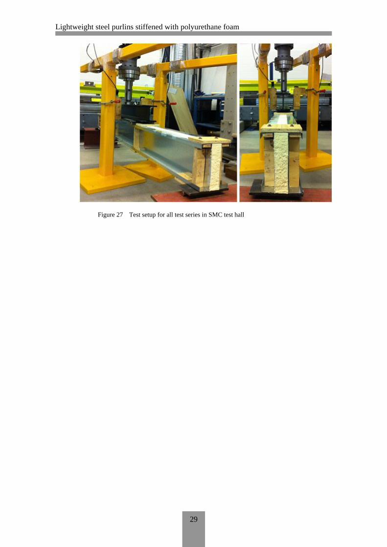
Test setup for all of the test series (see table 4) is shown in Figure 26. Fig-
ure 27 below, shows us how the schematic drawings of the test setup for
the series of two different cold-formed steel material types has been im-
plemented in the test.
Lightweight steel purlins stiffened with polyurethane foam
29
Figure 27 Test setup for all test series in SMC test hall
Lightweight steel purlins stiffened with polyurethane foam
30
4 TEST RESULTS, EVALUATION AND COMPARISON OF TEST
DATA
4.1 Failure modes
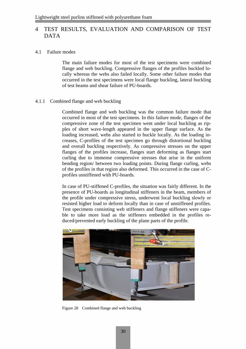
The main failure modes for most of the test specimens were combined
flange and web buckling. Compressive flanges of the profiles buckled lo-
cally whereas the webs also failed locally. Some other failure modes that
occurred in the test specimens were local flange buckling, lateral buckling
of test beams and shear failure of PU-boards.
4.1.1 Combined flange and web buckling
Combined flange and web buckling was the common failure mode that
occurred in most of the test specimens. In this failure mode, flanges of the
compressive zone of the test specimen went under local buckling as rip-
ples of short wave-length appeared in the upper flange surface. As the
loading increased, webs also started to buckle locally. As the loading in-
creases, C-profiles of the test specimen go through distortional buckling
and overall buckling respectively. As compressive stresses on the upper
flanges of the profiles increase, flanges start deforming as flanges start
curling due to immense compressive stresses that arise in the uniform
bending region/ between two loading points. During flange curling, webs
of the profiles in that region also deformed. This occurred in the case of C-
profiles unstiffened with PU-boards.
In case of PU-stiffened C-profiles, the situation was fairly different. In the
presence of PU-boards as longitudinal stiffeners in the beam, members of
the profile under compressive stress, underwent local buckling slowly or
resisted higher load to deform locally than in case of unstiffened profiles.
Test specimens consisting web stiffeners and flange stiffeners were capa-
ble to take more load as the stiffeners embedded in the profiles re-
duced/prevented early buckling of the plane parts of the profile.
Figure 28 Combined flange and web buckling

Lightweight steel purlins stiffened with polyurethane foam
31
4.1.2 Lateral buckling
Lateral buckling occurred in the unstiffened and in slender test specimens.
Test specimen from each test series 1 and 5 underwent this failure as un-
stiffened members were unable to stabilize themselves laterally as the
beam swayed towards the weaker axis. Although reinforcing the test spec-
imens after observing the first test specimen of test series 1 undergoing
lateral buckling failure, one of the test beams of test series 5 still failed in
this phenomenon. However, the load resistance of test series 5-specimen
was high because of its high sheet-steel material strength.
Figure 29 Lateral buckling of the test beam
In test series 1, test specimen 1, due to the profile members being very
slender, C-profiles deformed laterally against a very small load. Hence, it
was decided that LVL (Plywood) strips will be used, at both sides/profiles
at each support points and at each loading points. This implementation
proved to be worthy as other two test specimens gave a remarkably high
load resistance. Similarly, the same method was used in combination B to
laterally reinforce the C-profiles against lateral buckling. LVL strips were
introduced in test series 1, 2, 5 and 6. Test series 3 and test series 7 had an
extra PU-boards supporting flanges on each side of C-profiles connected
by small PU-strips on the support points and under the loading points to
simulate the contribution of LVL strips in test series 1, 2, 5 and 6.
4.1.3 Local flange buckling
Local flange buckling was observed in test series 4 test specimens. Test
specimens consisting slender wide flange profiles stiffened with PU-
boards of the same flange width failed under this buckling mode as com-
pressive stress in the upper wide flange purlin was very high. As the load-
ing was increased, region of flanges near the loading points deformed
permanently creating a curl of material in the compressed flange.

Lightweight steel purlins stiffened with polyurethane foam
32
Figure 30 Local flange buckling of wide flange profile
4.1.4 Shear failure of polyurethane boards
Shear failure of PU-board was observed in test series 8 as PU-stiffeners
failed in pure shear stresses. The reason that this phenomenon didn’t occur
in test series 4 was because of the material strength of the C-profile used
in that series. In test series 4, profiles of material strength 280N/mm2 were
used whereas in test series 8, 350N/mm2 material profiles were used. In
test series 4, the compressive stress that appeared in the compressive zone
of the upper wide flange profile was more than the bending stresses gener-
ated in the PU-board. Hence, the wide flange profile cross-section reached
its yield point faster than PU-board reaching its critical bending stress. On
the other hand, in test series 8, the strength of the C-profile was
350N/mm2 which means that the profile could withstand more compres-
sive stress due to bending. But the bending stiffness of PU-boards was not
high enough to withstand the bending stress in the test beam. As a result,
bending stiffness of PU-boards reached its limit before the profiles
reached their yield point and eventually the test specimens failed due to
high shear stresses in the PU-board. The angle made by the crack due to
the shear failure of PU-stiffener was between 40° to 55° as it can be clearly
observed in Figure 31.
Figure 31 Shear failure of the PU-board in test series 8

Lightweight steel purlins stiffened with polyurethane foam
33
4.2 Analysis of the test results
Table 4 shows us the test results obtained from the tests conducted for
each test series. Failure modes for each test specimen have also been de-
scribed in the table. As we can see in the table, the major failure mode in
the whole test was combined flange and web buckling. Average load has
been calculated making it easier to compare the load resistance of each se-
ries containing the same sheet-steel material for the specimen. However,
test series 4 will compared to test series 8 as both test series contain the
same profile cross-section despite their varying thickness and material
properties. Also, standard deviation for each test series has also been cal-
culated to know the extent of the fluctuation of test value from its average
result.
Table 5 Test results of the conducted test
1 This value of ultimate load for the first specimen of S280_0,5_Series1
was not taken into consideration as the test on the specimen did not
provide any bending stiffness values due to predominant lateral buck-
ling failure of the beam.
The average ultimate load provided by various combinations/beam types
of two different sheet-steel material types have been compared graphically
in Figure 32. Also, the average ultimate load capacities have been ex-
pressed in percentage ratio and can be observed in Figure 33.
Specimen no. Force (kN) Failure mode Average (kN) Std. Deviation (kN)
1 0,92 ¹ Lateral buckling
2 6,47 Flange+web buckling
3 5,14 Flange+web buckling
1 10,38 Flange+web buckling
2 9,58 Flange+web buckling
3 10,97 Flange+web buckling
1 12,71 Flange+web buckling
2 10,1 Flange+web buckling
3 12,39 Flange+web buckling
1 4,96 Local Buckling
2 4,97 Local Buckling
3 5,2 Local Buckling
1 15,98 Lateral buckling
2 21,8 Lateral+member buckling
1 26,1 Flange+web buckling
2 26,06 Flange+web buckling
1 27,1 Flange buckling
2 28,78 Flange buckling
1 4,27 Shear failure of PU
2 6,96 Shear failure of PU5,62 1,90
18,89 4,12
27,94 1,19
10,31 0,70
5,04 0,14
26,08 0,03
5,81 0,94
11,73 1,42
S350_1,0_A_Series5
S350_1,0_B_Series6
S350_1,0_C_Series7
S350_1,0_D_Series8
Name of the series
S280_0,5_A_Series1
S280_0,5_B_Series2
S280_0,5_C_Series3
S280_0,5_D_Series4

Lightweight steel purlins stiffened with polyurethane foam
34
Figure 32 Average load capacities of three beam types of two different steel grades
Figure 33 Percentage ratio of load resistances of beam types A, B and C with two dif-
ferent steel grades
The average ultimate load of test series-Series1 was 5,81 kN. Similarly,
for test series 2, the average ultimate load resistance was 10,31 kN which
is 77% more than that of test series1. For test series 3, the average ultimate
load was 11,73 kN which is 102% more compared to test series 1. Fur-
thermore, in test series S350, test series 5 could bear average maximum of
18,89 kN of load. On the other hand, average ultimate load capacity of test
series 6 was 26,08 kN which is 38% more compared to test series 5. Test
series 7 could resist 48% more load (27,94 kN) compared to the load of
test series 5.
5,81
18,89
10,31
26,08
11,73
27,94
0
5
10
15
20
25
30
S280+Z275 S350+Z275
Ave
rage
ult
imat
e lo
ad (
kN)
Sheet-steel materials
Beam type A
Beam type B
Beam type C
100% 100%
177%
138%
202%
148%
0%
50%
100%
150%
200%
250%
S280+Z275 S350+Z275
Ave
rage
ult
imat
e lo
ad (
%)
Sheet-steel materials
Beam type A
Beam type B
Beam type C

Lightweight steel purlins stiffened with polyurethane foam
35
The gradual increase of both ultimate load of the beam as well as the slope
of the graph of each specimen can be observed as we move from beam-
type A to C in each sheet-steel material type. As we move from beam-type
A to C, the amount of PU-stiffeners in a test beam also increases. It means
that the PU-boards present in each PU-stiffened beam were able to func-
tion as longitudinal stiffeners. The PU-boards used in stiffening the profile
reduced/prevented buckling phenomena of the beam and provided an extra
stiffness to the beam. This stiffening of C-purlins provided by PU-boards
is thoroughly shown below.
Failure modes rather remained the same (combined flange and web buck-
ling) among the test conducted specimens. However, lateral and member
buckling failure was observed in S350_1,0_A_Series5 specimens.
Figure 34 Avg. ultimate load of beam type D for both sheet-steel materials
Figure 34 illustrates the average load bearing capacities of beam-type D
for both C-profile types. As shown in the figure, S350_1,0_D_Series8 has
12% more load bearing resistance than that of test series 4.
Lightweight steel purlins stiffened with polyurethane foam
36
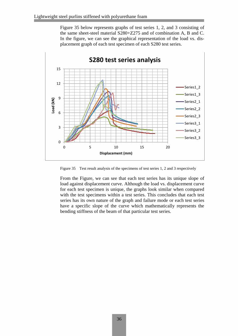
Figure 35 below represents graphs of test series 1, 2, and 3 consisting of
the same sheet-steel material S280+Z275 and of combination A, B and C.
In the figure, we can see the graphical representation of the load vs. dis-
placement graph of each test specimen of each S280 test series.
Figure 35 Test result analysis of the specimens of test series 1, 2 and 3 respectively
From the Figure, we can see that each test series has its unique slope of
load against displacement curve. Although the load vs. displacement curve
for each test specimen is unique, the graphs look similar when compared
with the test specimens within a test series. This concludes that each test
series has its own nature of the graph and failure mode or each test series
have a specific slope of the curve which mathematically represents the
bending stiffness of the beam of that particular test series.
0
3
6
9
12
15
0 5 10 15 20
Load
(kN
)
Displacement (mm)
S280 test series analysis
Series1_2
Series1_3
Series2_1
Series2_2
Series2_3
Series3_1
Series3_2
Series3_3
Lightweight steel purlins stiffened with polyurethane foam
37
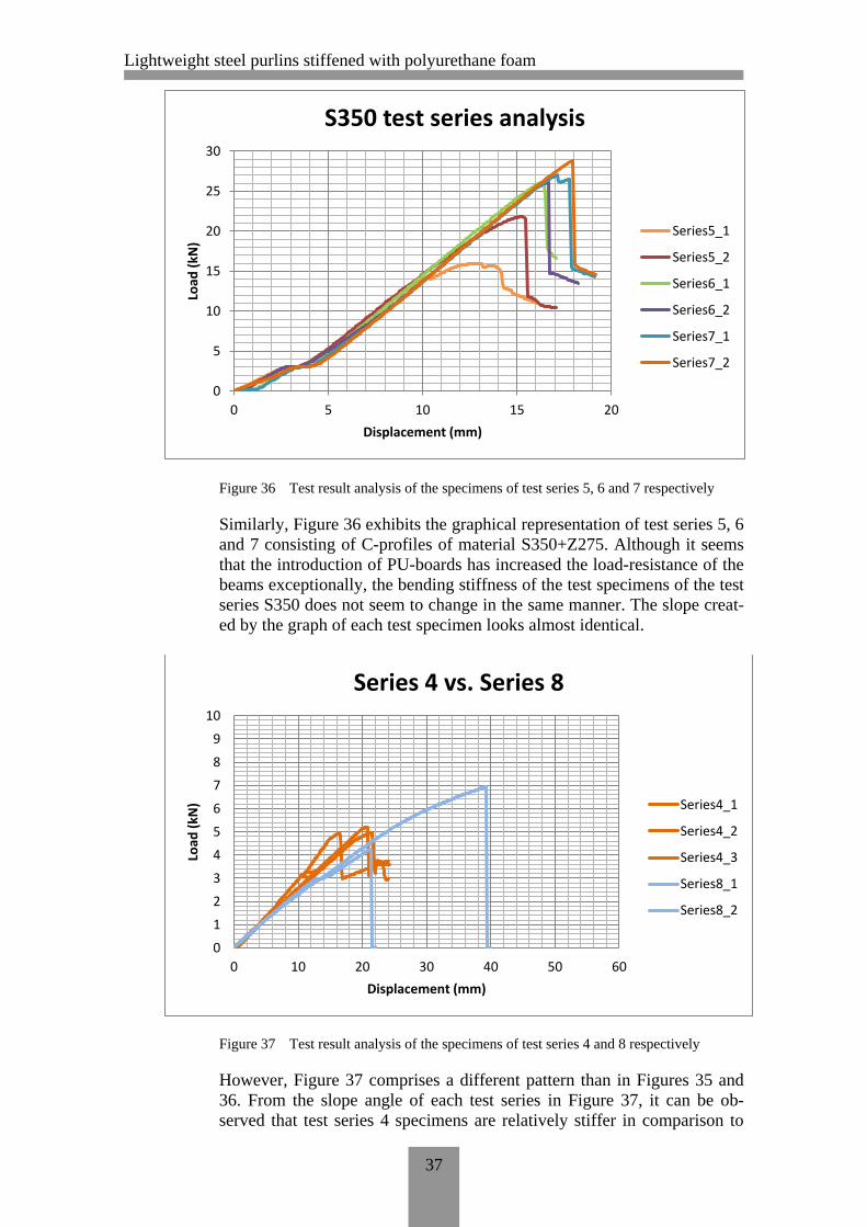
Figure 36 Test result analysis of the specimens of test series 5, 6 and 7 respectively
Similarly, Figure 36 exhibits the graphical representation of test series 5, 6
and 7 consisting of C-profiles of material S350+Z275. Although it seems
that the introduction of PU-boards has increased the load-resistance of the
beams exceptionally, the bending stiffness of the test specimens of the test
series S350 does not seem to change in the same manner. The slope creat-
ed by the graph of each test specimen looks almost identical.
Figure 37 Test result analysis of the specimens of test series 4 and 8 respectively
However, Figure 37 comprises a different pattern than in Figures 35 and
36. From the slope angle of each test series in Figure 37, it can be ob-
served that test series 4 specimens are relatively stiffer in comparison to
0
5
10
15
20
25
30
0 5 10 15 20
Load
(kN
)
Displacement (mm)
S350 test series analysis
Series5_1
Series5_2
Series6_1
Series6_2
Series7_1
Series7_2
0
1
2
3
4
5
6
7
8
9
10
0 10 20 30 40 50 60
Load
(kN
)
Displacement (mm)
Series 4 vs. Series 8
Series4_1
Series4_2
Series4_3
Series8_1
Series8_2

Lightweight steel purlins stiffened with polyurethane foam
38
the specimens from test series 8. Also, the failure modes for the two of
these test series were completely different. Test series 4 failed in local
flange buckling whereas test series failed under pure shear failure of PU-
boards. This happened, because, in case of test series 4, the PU-boards
were able to stiffen the compressed flange of the upper wide-flange pro-
files against local buckling. However, in case of test series 8, the shear
failure of the PU-boards of the test beam was because of the development
of critical shear stresses in the PU-board. Shear stress in the PU-board was
higher than any critical buckling stresses arising on the wide-flange profile
as no buckling phenomena was observed during test series 8 loading. The
shear resistance of the PU-board was much less compared to the buckling
resistance of the compressed flange of the profile in test series 8. As the
shear stresses became immense in the PU-board, it failed ultimately in
shear even before the compressed profiles started showing any of the
buckling modes.
As for the implementation of the test results to determine the bending
stiffness of each test series, an equation is introduced to determine the de-
flection in case of a simply supported beam loaded by two equal concen-
trated loads symmetrically placed between the supports.
For a simple beam with two equally concentrated loads symmetrically
placed between the two loading points and the support points, the deflec-
tion created by the force on that beam is given by,
( )( ) (1)
where,
F maximum force taken by the test beam before failing
a distance between the loading point and support
l span of the test beam
However, equation 1 applies in cases only when the bending stress caused
by the applied load lies within the linear elastic region of the load vs. dis-
placement graph. There are some linear parts of the graph that represent
the bending stiffness of the beam. Hence, an imaginary tangent line can be
drawn on the linear elastic region (approximately around 10% to 30% of
the ultimate load of the beam) of the graph that will represent the tangent
bending stiffness of the beam. Also, a straight line can be drawn between
the origin and ultimate load point creating another sloped line known as
“secant bending stiffness” of the beam. These two lines represent two dif-
ferent bending stiffnesses of the same beam. Tangent bending stiffness of
slope α is greater in value compared to the secant bending stiffness that
has β as inclination angle.
The statements made above can be verified in Figure 38. The figure also
shows how the deflection/displacement created in the beam can be fluctu-
ated by the load applied to the beam. However, Figure 38 only demon-
strates the nature of the graph and each test specimen may have its own
graphical representation of its unique nature.
Lightweight steel purlins stiffened with polyurethane foam
39
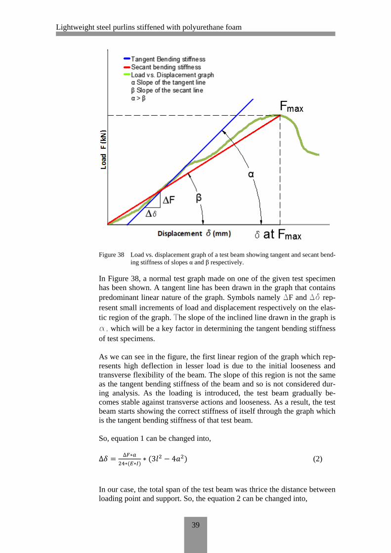
Figure 38 Load vs. displacement graph of a test beam showing tangent and secant bend-
ing stiffness of slopes α and β respectively.
In Figure 38, a normal test graph made on one of the given test specimen
has been shown. A tangent line has been drawn in the graph that contains
predominant linear nature of the graph. Symbols namely ∆F and ∆δ rep-
resent small increments of load and displacement respectively on the elas-
tic region of the graph. The slope of the inclined line drawn in the graph is
α, which will be a key factor in determining the tangent bending stiffness
of test specimens.
As we can see in the figure, the first linear region of the graph which rep-
resents high deflection in lesser load is due to the initial looseness and
transverse flexibility of the beam. The slope of this region is not the same
as the tangent bending stiffness of the beam and so is not considered dur-
ing analysis. As the loading is introduced, the test beam gradually be-
comes stable against transverse actions and looseness. As a result, the test
beam starts showing the correct stiffness of itself through the graph which
is the tangent bending stiffness of that test beam.
So, equation 1 can be changed into,
( ) ( ) (2)
In our case, the total span of the test beam was thrice the distance between
loading point and support. So, the equation 2 can be changed into,
Lightweight steel purlins stiffened with polyurethane foam
40
( )
(3)
So, the bending stiffness of the test beam depends on the small change of
load in the beam as the small change in loading changes the deflection of
the beam under loading by a small amount. So equation 2 can further be
modified into,
( )
(
) (4)
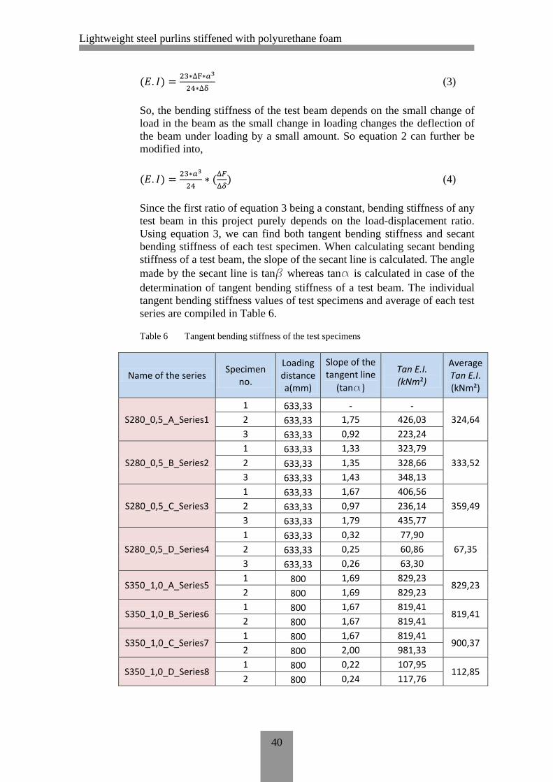
Since the first ratio of equation 3 being a constant, bending stiffness of any
test beam in this project purely depends on the load-displacement ratio.
Using equation 3, we can find both tangent bending stiffness and secant
bending stiffness of each test specimen. When calculating secant bending
stiffness of a test beam, the slope of the secant line is calculated. The angle
made by the secant line is tanβ whereas tanα is calculated in case of the
determination of tangent bending stiffness of a test beam. The individual
tangent bending stiffness values of test specimens and average of each test
series are compiled in Table 6.
Table 6 Tangent bending stiffness of the test specimens
Name of the series Specimen
no.
Loading distance a(mm)
Slope of the tangent line
(tanα)
Tan E.I. (kNm²)
Average Tan E.I. (kNm²)
S280_0,5_A_Series1
1 633,33 - -
324,64 2 633,33 1,75 426,03
3 633,33 0,92 223,24
S280_0,5_B_Series2
1 633,33 1,33 323,79
333,52 2 633,33 1,35 328,66
3 633,33 1,43 348,13
S280_0,5_C_Series3
1 633,33 1,67 406,56
359,49 2 633,33 0,97 236,14
3 633,33 1,79 435,77
S280_0,5_D_Series4
1 633,33 0,32 77,90
67,35 2 633,33 0,25 60,86
3 633,33 0,26 63,30
S350_1,0_A_Series5 1 800 1,69 829,23
829,23 2 800 1,69 829,23
S350_1,0_B_Series6 1 800 1,67 819,41
819,41 2 800 1,67 819,41
S350_1,0_C_Series7 1 800 1,67 819,41
900,37 2 800 2,00 981,33
S350_1,0_D_Series8 1 800 0,22 107,95
112,85 2 800 0,24 117,76

Lightweight steel purlins stiffened with polyurethane foam
41
Also, the secant bending stiffness of the test specimens are mentioned in
Table 7. Later, the two bending stiffness values are compared with one an-
other.
Table 7 Secant bending stiffness of the test specimens
Comparison of tangent bending stiffness of test series 1, 2, 3 of sheet-steel
type S280+Z275 and 5, 6, 7 of sheet-steel type S350+Z275 are presented
as graphical representation in Figure 39. In the figure, percentage compar-
ison of tangent bending stiffness has also been made in order to determine
the most effective combination of C-profile and PU-stiffener.
Specimen
no.
Loading
distance
a(mm)
Max. load
F (kN)
Displacement
at max. Load
δ (mm)
Slope of the
secant line
(tanβ)
Sec E.I.
(kNm ²)
Average
Sec E.I .
(kNm²)
1 633,33 0,92 43,52 - -
2 633,33 6,47 9,07 0,71 173,66
3 633,33 5,14 7,76 0,66 161,25
1 633,33 10,38 8,57 1,21 294,87
2 633,33 9,58 8,64 1,11 269,93
3 633,33 10,97 8,28 1,32 322,54
1 633,33 12,71 7,42 1,71 417,01
2 633,33 10,1 9,35 1,08 262,98
3 633,33 12,39 7,28 1,70 414,33
1 633,33 4,96 16,33 0,30 73,94
2 633,33 4,97 21,36 0,23 56,65
3 633,33 5,2 20,68 0,25 61,22
1 800 15,98 13,06 1,22 600,37
2 800 21,8 15,12 1,44 707,44
1 800 26,1 16,3 1,60 785,67
2 800 26,06 16,58 1,57 771,22
1 800 27,1 17,1 1,58 777,61
2 800 28,78 17,98 1,60 785,39
1 800 4,27 21,41 0,20 97,86
2 800 6,96 39,33 0,18 86,83
778,44
781,50
92,34
167,46
295,78
364,77
63,93
653,91S350_1,0_A_Series5
S350_1,0_B_Series6
S350_1,0_C_Series7
S350_1,0_D_Series8
Name of the series
S280_0,5_A_Series1
S280_0,5_B_Series2
S280_0,5_C_Series3
S280_0,5_D_Series4

Lightweight steel purlins stiffened with polyurethane foam
42
Figure 39 Comparison of tangent bending stiffness of beam types A, B and C of each
sheet-steel type.
Similarly, comparison of secant bending stiffness of test series 1, 2, 3 of
sheet-steel type S280+Z275 and 5, 6, 7 of sheet-steel type S350+Z275 are
presented as graphical representation in Figure 40. In the figure, percent-
age comparison of secant bending stiffness has also been made in order to
determine the most effective combination of C-profile and PU-stiffener.

Lightweight steel purlins stiffened with polyurethane foam
43
Figure 40 Comparison of secant bending stiffness of beam types A, B and C of each
sheet-steel type
Also, both tangent bending stiffness and secant bending stiffness for
beam-type D have been mentioned in Figure 41.

Lightweight steel purlins stiffened with polyurethane foam
44
Figure 41 Tangent bending stiffness and secant bending stiffness values of beam type D
for both sheet-steel types.
Figure 39 demonstrates the comparison chart regarding average tangent
bending stiffness values for beam types A, B and C. In Figure 39, it can be
observed that the performance of PU-stiffeners in both of the sheet-steel
types is very similar to one another. As it can be seen in the figure, for
sheet-steel type S280+Z275, the calculated average value of tangent bend-
ing stiffness for test series 1 is 324,6 kNm2. Similarly, test series 2 indi-
cates 333,5 kNm2
which is 3% more compared to test series 1 whereas ac-
cording to the data, test series 3 is 11% more stiffer compared to series 1.
Similarly, for sheet-steel type S350+Z275, average tangent bending stiff-
ness values for test series 5 is 829 kNm2. For test series 6, the value is
819,4 kNm2 which is almost equal to the test series 5. In case of test series
7, the average tangent bending stiffness value is 900,4 kNm2, 9% stiffer
than series 5.
These varying results of tangent bending stiffness of each test series with-
in a same sheet-steel material type depend on the position of PU-stiffeners
in the beam. Despite specimens made of S350+Z275 sheet-steel material
type are thicker (1.0mm) and longer (2.5 m) than that of S280+Z275
(0.5mm and 2.0 m), the C-profile cross-section are of the same dimension.
This enables both of the specimens to exhibit similar nature of buckling
phenomena and failure modes. In beam type A (for both sheet-steel types),
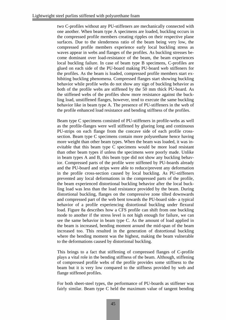
Lightweight steel purlins stiffened with polyurethane foam
45
two C-profiles without any PU-stiffeners are mechanically connected with
one another. When beam type A specimens are loaded, buckling occurs in
the compressed profile members creating ripples on their respective plane
surfaces. Due to the slenderness ratio of the beam being very low, the
compressed profile members experience early local buckling stress as
waves appear in webs and flanges of the profiles. As buckling stresses be-
come dominant over load-resistance of the beam, the beam experiences
local buckling failure. In case of beam type B specimens, C-profiles are
glued on each side of the PU-board making PU-board web stiffeners for
the profiles. As the beam is loaded, compressed profile members start ex-
hibiting buckling phenomena. Compressed flanges start showing buckling
behavior while profile webs do not show any sign of buckling behavior as
both of the profile webs are stiffened by the 50 mm thick PU-board. As
the stiffened webs of the profiles show more resistance against the buck-
ling load, unstiffened flanges, however, tend to execute the same buckling
behavior like in beam type A. The presence of PU-stiffeners in the web of
the profile enhanced load resistance and bending stiffness of the profiles.
Beam type C specimens consisted of PU-stiffeners in profile-webs as well
as the profile-flanges were well stiffened by glueing long and continuous
PU-strips on each flange from the concave side of each profile cross-
section. Beam type C specimens contain more polyurethane hence having
more weight than other beam types. When the beam was loaded, it was in-
evitable that this beam type C specimens would be more load resistant
than other beam types if unless the specimens were poorly made. Unlike
in beam types A and B, this beam type did not show any buckling behav-
ior. Compressed parts of the profile were stiffened by PU-boards already
and the PU-board and strips were able to reduce/prevent any deformation
in the profile cross-section caused by local buckling. As PU-stiffeners
prevented any local deformations in the compressed parts of the profile,
the beam experienced distortional buckling behavior after the local buck-
ling load was less than the load resistance provided by the beam. During
distortional buckling, flanges on the compressive zone tilted downwards
and compressed part of the web bent towards the PU-board side- a typical
behavior of a profile experiencing distortional buckling under flexural
load. Figure 8a describes how a CFS profile can shift from one buckling
mode to another if the stress level is not high enough for failure, we can
see the same behavior in beam type C. As the amount of load applied in
the beam is increased, bending moment around the mid-span of the beam
increased too. This resulted in the generation of distortional buckling
where the bending moment was the highest, making the beam vulnerable
to the deformations caused by distortional buckling.
This brings to a fact that stiffening of compressed flanges of C-profile
plays a vital role in the bending stiffness of the beam. Although, stiffening
of compressed profile webs of the profile provides some stiffness to the
beam but it is very low compared to the stiffness provided by web and
flange stiffened profiles.
For both sheet-steel types, the performance of PU-boards as stiffener was
fairly similar. Beam type C held the maximum value of tangent bending

Lightweight steel purlins stiffened with polyurethane foam
46
stiffness for both sheet-steel types. According to the retrieved data, it can
be expressed that the use of PU-stiffeners can increase the bending stiff-
ness of stiffened C-profiles by approximately 10% than the ones without
PU-stiffeners.
On the other hand, the secant bending stiffness of test specimens gives us
a phenomenal difference in stiffness values of each test series. However,
the average value secant bending stiffness of each test series must be less
than that of tangent bending stiffness and it is less in every test series. The
average value of secant bending stiffness for test series 5 is 167,46 kNm2.
For test series 6, the value is 295,78 kNm2, 77% stiffer than series 5. Test
series 7 holds 364,77 kNm2 which is 118% more of test series 5. (Figure
40)
Figure 41 demonstrates both stiffness values for beam type D of both
sheet-steel material types. Average tangent bending stiffness of test series
4 and 6 are 67,4 kNm2 and 112,9 kNm
2 respectively. Similarly, average
secant bending stiffness values of series 4 and 6 are 63,93 kNm2 and 92,34
kNm2 respectively.
However, tangent bending stiffness of the beam is more precise than se-
cant bending stiffness as tangent bending stiffness only considers a linear
inclination of the elastic region of the graph whereas secant bending stiff-
ness is determined by considering maximum load capacity of the beam
and the displacement of the beam during the maximum loading.
From Table 5 and the analysis done above, it can be concluded that,
(5)
Similarly, taking Table 6 as reference, the tangent bending stiffness of
both sheet-steel types for beam type B is similar to beam type A and beam
type C greater than beam type B. This relation can be observed in equation
5.
( ) ( ) ( ) (6)
Also, calculated values of bending stiffness of C-profiles with brutto and
effective cross-section for both sheet-steel materials are shown in Table 8.
The values shown in the table are for unstiffened C-profile beam that con-
sists of two identical profiles.
Table 8 Calculated values of bending stiffness of unstiffened C-profiles with brutto
and effective cross-sections for both sheet-steel material types
Sheet-steel material EI for brutto cross-
section (kNm2)
EI for effective cross-
section (kNm2)
S280+Z275 413,09 216,47
S350+Z275 815,82 628,18

Lightweight steel purlins stiffened with polyurethane foam
47
Brutto value of bending stiffness of a C-profile is the total bending stiff-
ness provided by the profile when the cross-section is fully functioning
and doesn’t contain any ineffective parts. This case exists only when the
purlin experiences pure tensile load only. When a purlin is loaded in pure
compression or in bending, the compressed part of the purlin will create
ineffective parts in the cross-section meaning those regions will be unable
to take any compressive or bending stresses. This is due to the slender na-
ture of the purlin. So whenever a purlin is loaded in compression or in
bending, compressed zones of the slender purlin will automatically create
ineffective parts and these ineffective parts cannot be considered as load-
bearing profile members. Hence a new bending stiffness is required where
the bending stiffness is calculated by considering the effective cross-
section of the profile. Effective bending stiffness is always less than the
brutto bending stiffness of a purlin. The calculations regarding the deter-
mination of the bending stiffness of S350 sheet-steel material type for
brutto and effective cross-section C-profile is shown in Appendix 4. Same
calculation method can be used for S280 sheet-steel material.
Comparing the tangent bending stiffness of unstiffened C-profiles of both
sheet-steel materials to the calculated effective bending stiffness of un-
stiffened C-profiles for both sheet-steel materials will lead us to equation 6
and 7.
(7)
(8)
Equation 6 and equation 7 give us a ratio between the value obtained from
the carried test and the value calculated considering the effective cross-
section of the C-profile. The ratio obtained in equations 6 and 7 seem to be
a viable ratio as the values obtained from the test results always must be
greater than the design value (calculated value). Equation 7 and 8 shows
us the ratio of the test results to the design value for the bending stiffness-
es for both sheet-steel types namely, S280 and S350 are 1,5 and 1,32 re-
spectively.
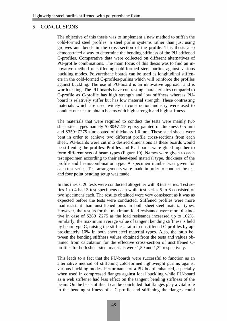
Lightweight steel purlins stiffened with polyurethane foam
48
5 CONCLUSIONS
The objective of this thesis was to implement a new method to stiffen the
cold-formed steel profiles in steel purlin systems rather than just using
grooves and bends in the cross-section of the profile. This thesis also
demonstrated a way to determine the bending stiffness of the PU-stiffened
C-profiles. Comparative data were collected on different alternatives of
PU-profile combinations. The main focus of this thesis was to find an in-
novative method of stiffening cold-formed steel purlins against various
buckling modes. Polyurethane boards can be used as longitudinal stiffen-
ers in the cold-formed C-profiles/purlins which will reinforce the profiles
against buckling. The use of PU-board is an innovative approach and is
worth testing. The PU-boards have contrasting characteristics compared to
C-profile as C-profile has high strength and low stiffness whereas PU-
board is relatively stiffer but has low material strength. These contrasting
materials which are used widely in construction industry were used to
conduct our test to obtain beams with high strength and high stiffness.
The materials that were required to conduct the tests were mainly two
sheet-steel types namely S280+Z275 epoxy painted of thickness 0.5 mm
and S350+Z275 zinc coated of thickness 1.0 mm. These steel sheets were
bent in order to achieve two different profile cross-sections from each
sheet. PU-boards were cut into desired dimensions as these boards would
be stiffening the profiles. Profiles and PU-boards were glued together to
form different sets of beam types (Figure 19). Names were given to each
test specimen according to their sheet-steel material type, thickness of the
profile and beam/combination type. A specimen number was given for
each test series. Test arrangements were made in order to conduct the test
and four point bending setup was made.
In this thesis, 20 tests were conducted altogether with 8 test series. Test se-
ries 1 to 4 had 3 test specimens each while test series 5 to 8 consisted of
two specimens each. The results obtained were very consistent as it was as
expected before the tests were conducted. Stiffened profiles were more
load-resistant than unstiffened ones in both sheet-steel material types.
However, the results for the maximum load resistance were more distinc-
tive in case of S280+Z275 as the load resistance increased up to 102%.
Similarly, the maximum average value of tangent bending stiffness is held
by beam type C, raising the stiffness ratio to unstiffened C-profiles by ap-
proximately 10% in both sheet-steel material types. Also, the ratio be-
tween the bending stiffness values obtained from the tests and values ob-
tained from calculation for the effective cross-section of unstiffened C-
profiles for both sheet-steel materials were 1,50 and 1,32 respectively.
This leads to a fact that the PU-boards were successful to function as an
alternative method of stiffening cold-formed lightweight purlins against
various buckling modes. Performance of a PU-board enhanced, especially
when used in compressed flanges against local buckling while PU-board
as a web stiffener had less effect on the tangent bending stiffness of the
beam. On the basis of this it can be concluded that flanges play a vital role
in the bending stiffness of a C-profile and stiffening the flanges could

Lightweight steel purlins stiffened with polyurethane foam
49
prove to be a very effective way to increase the bending stiffness of the
profile.
Since the method of stiffening lightweight purlins by polyurethane is a
cheap and effective way to increase the bending stiffness of the beam,
there is a tendency that these stiffened C-profiles can be mass-produced.
Changing profile cross-section dimensions, altering positions of PU-board
as necessary, altering the thickness of PU-board between two profiles can
be done in order to make it more applicable in the construction industry.
However, there should be more tests regarding the performance of polyu-
rethane if alterations are to be made.
Some of the test results did not meet the expectations as there may have
been a few flaws regarding specimen preparation or some errors during
test setup. Test series S280_0,5_A_Series1_1 specimen was one of them
as the test specimen was not reinforced against lateral actions due to the
loading. Also, in case of test specimen S280_0,5_B_Series2_2, one of the
position of LVL/plywood board under the loading point was misplaced
which might have altered the test results.
All the graphs and Figures of all test specimens of all test series are de-
scribed in Appendix 1 and Appendix 2.
This project can be improved to obtain more accurate and detailed data if
the manufacture of test specimens are done more carefully and under
closed senior supervision. The use of cold-formed profiles with smaller
thickness is recommended as the results clearly showed that stiffening of
thin C-profiles by PU-boards gives more productive results in this project.

Lightweight steel purlins stiffened with polyurethane foam
50
SOURCES
Anchorage reinforcement n.d. ’Deck of facts online. Accessed 27th
Sep-
tember 2011.
http://www.bluescopesteelasia.com/bluescopesteel/product/structuraldecki
ng/deckingprint.cfm?content=term&ID=65bbb582-fce9-4d7f-b61c-
f5e18323564d
Ben Young. ’Local buckling and shift of effective centroid of slender sec-
tions. Accessed 26th
September 2011, pdf-file.
http://www.hkisc.org/proceedings/2006421/9_Ben-Young.pdf
EN 1993-1-3. 2006. Design of steel structures. Part 1-1: General rules and
rules for buildings. Accessed 2nd
July 2010, pdf-file.
http://sales.sfs.fi/servlets/SFSContractServlet?action=enterContract&contr
actId=10105
EN 1993-1-3. 2006. Design of steel structures. Part 1-3: General rules.
Supplementary rules for cold-formed members and sheeting. Accessed 2nd
July 2010, pdf-file.
http://sales.sfs.fi/servlets/SFSContractServlet?action=enterContract&contr
actId=10105
Fagerberg, L. 2003. ’Wrinkling of sandwich panels for marine applica-
tions. Accessed 28th
September 2011, pdf-file.
kth.diva-portal.org/smash/get/diva2:9408/FULLTEXT01
Garner, L. and Nathercot, D.A. 2005. ’Designers’ guide to EN 1993-1-1
Eurocode 3: Design of steel structures, general rules and rules for build-
ings.
London, Thomas Telford Ltd, 2005.
HAMK 2011. ’Sheet Metal Center. Accessed 26th
September 2011.
http://portal.hamk.fi/portal/page/portal/HAMK/Tutkimus_ja_kehitys/Osaa
miskeskittymat/Ohutlevykeskus
Hancock, G. J. and Pham, C. H. 2007a. ’Shear buckling of thin-walled
channel sections. Accessed 27th
September 2011, pdf-file.
http://sydney.edu.au/engineering/civil/publications/r885.pdf
Hancock, G. J. and Pham, C. H. 2007b. ’Direct strength design of cold-
formed purlins. Accessed 27th
September 2011, pdf-file.
http://sydney.edu.au/engineering/civil/publications/r882.pdf
Kingspan multibeam 2007. ’Rail and purlin system. Accessed 27th
Sep-
tember 2011, pdf-file.
http://www.kingspanliterature.co.uk/kip/ire/pdf/product-
literature/kingspan_multibeam.pdf

Lightweight steel purlins stiffened with polyurethane foam
51
Lau, S. C. W. & Hancock, G. J. 1986.’Buckling of thin flat-walled struc-
tures by a spline finite strip method, thin-walled structures, Vol. 4, pdf-
file.
http://www.sciencedirect.com.proxy.hamk.fi:2048/science/article/pii/0263
823186900340
Mahendran, M. and Mcandrew, D. 2003. ’Flexural wrinkling strength of
lightly profiled sandwich panels with transverse joint in the foam core.
Accessed 28th
September 2011, pdf-file.
http://eprints.qut.edu.au/7619/1/7619.pdf
Metsec n.d. ’Z-section butt purlin system. Accessed 27th
September 2011.
http://www.metsec.com/products/cold-rolled-steel-purlins/steel-purlins-Z-
sections.asp
Pierre Bourrier. ’European Lightweight Steel-framed Construction. Ac-
cessed 6th
September 2011, pdf-file.
http://www.constructalia.com/en_EN/publications/european-lightweight-
steel-frame-construction/4773203/279970/page.jsp
Scott D. Cortese. ’Investigation of single span Z-section purlins supporting
standing seam roof system considering distortional buckling. Accessed
26th
September 2011, pdf-file.
http://scholar.lib.vt.edu/theses/available/etd-07272001-
205847/unrestricted/Thesis.pdf
Staal, R.A, Horrigan, D.P.W, Mallison, G.D and Jayaraman, K n.d. ’Wrin-
kling stresses in honeycomb sandwich panels using discrete and continu-
um core representations, pdf-file.
http://extra.ivf.se/eccm13_programme/abstracts/1935.pdf
Steadman and Son. ’Metal roofing and cladding systems. Accessed 26th
September 2011.
http://www.steadmans.co.uk/product/purlins/index.htm
The Steel Framing Alliance. ’A builder’s guide to steel frame construction.
Accessed 26th
September 2011, pdf-file.
http://www.steelframing.org/PDF/SFA_Framing_Guide_final%202.pdf
Wei-Wen Yu center for Cold-Formed Steel Structures 2008. ’Cold-formed
steel design for the students. Accessed 28th
September 2011, pdf-file.
http://www.ccfssonline.org/Student/other/SDM%20Chapter%20C%20-
%200708.pdf

Lightweight steel purlins stiffened with polyurethane foam
Appendix 1 (1/8)
TEST GRAPHS AND FIGURES OF S280 TEST SERIES
Figure 1 S280_0,5_A_Series1
Figure 2 Lateral buckling failure (Series1_1)
0
1
2
3
4
5
6
7
8
9
10
0 5 10 15 20
Load
(kN
)
Displacement (mm)
S280_0,5_A_Series1
Series1_1
Series1_2
Series1_3

Lightweight steel purlins stiffened with polyurethane foam
Appendix 1 (2/8)
Figure 3 Local member buckling failure (Series 1_2)
Figure 4 Local flange and web buckling failure/web crushing (Series 1_3)

Lightweight steel purlins stiffened with polyurethane foam
Appendix 1 (3/8)
Figure 5 S280_0,5_B_Series2
Figure 6 Local flange buckling failure (Series 2_1)
0
3
6
9
12
15
0 5 10 15 20
Load
(kN
)
Displacement (mm)
S280_0,5_B_Series2
Series2_1
Series2_2
Series2_3

Lightweight steel purlins stiffened with polyurethane foam
Appendix 1 (4/8)
Figure 7 Local flange buckling failure (Series 2_2)
Figure 8 Local flange and web buckling failure (Series 2_3)

Lightweight steel purlins stiffened with polyurethane foam
Appendix 1 (5/8)
S280_0,5_C_Series3_1 maximum load 12,71 kN
Figure 9 Local flange buckling failure (Series 3_1)
0
3
6
9
12
15
0 5 10 15 20
Load
(kN
)
Displacement (mm)
S280_0,5_C_Series3
Series3_1
Series3_2
Series3_3
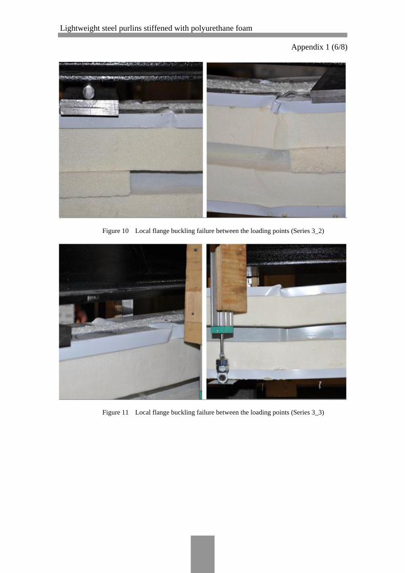
Lightweight steel purlins stiffened with polyurethane foam
Appendix 1 (6/8)
Figure 10 Local flange buckling failure between the loading points (Series 3_2)
Figure 11 Local flange buckling failure between the loading points (Series 3_3)
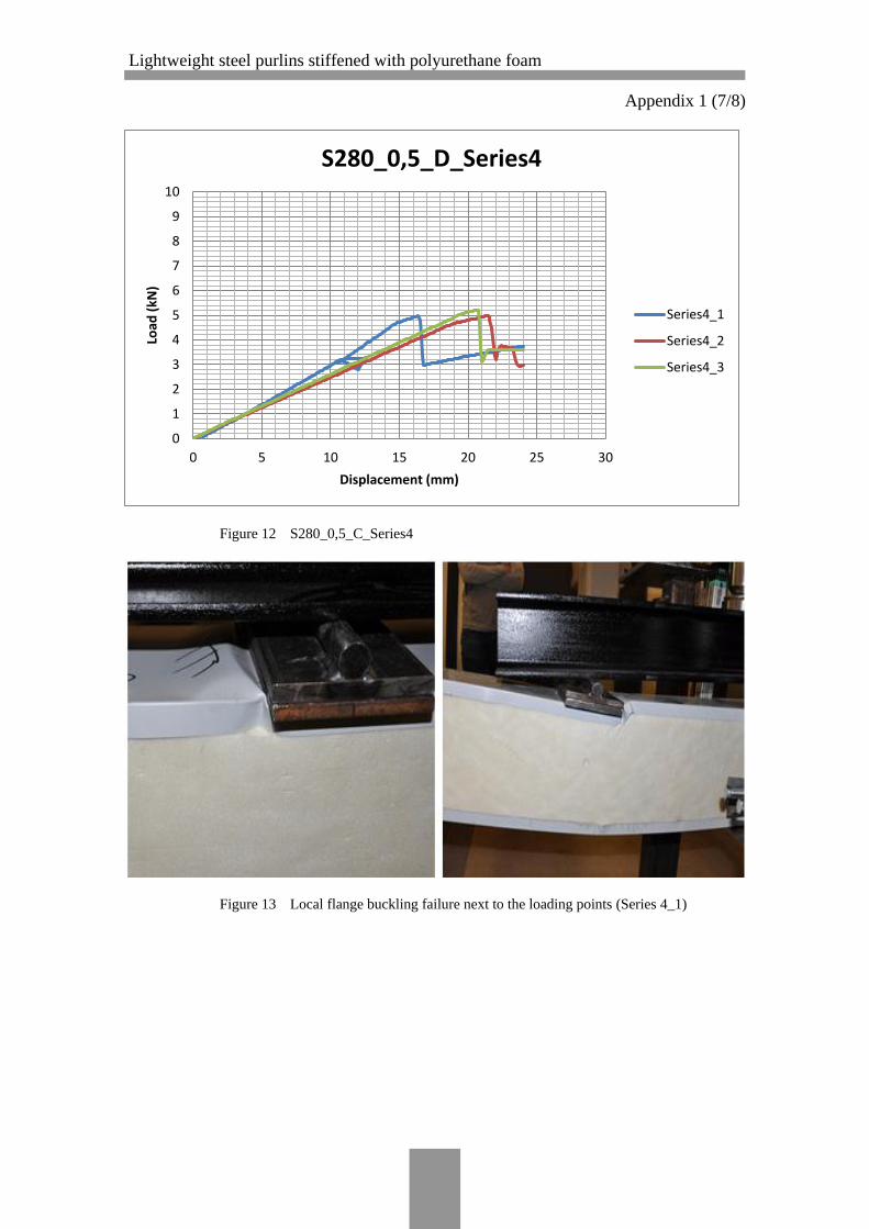
Lightweight steel purlins stiffened with polyurethane foam
Appendix 1 (7/8)
Figure 12 S280_0,5_C_Series4
Figure 13 Local flange buckling failure next to the loading points (Series 4_1)
0
1
2
3
4
5
6
7
8
9
10
0 5 10 15 20 25 30
Load
(kN
)
Displacement (mm)
S280_0,5_D_Series4
Series4_1
Series4_2
Series4_3

Lightweight steel purlins stiffened with polyurethane foam
Appendix 1 (8/8)
Figure 14 Local flange buckling failure next to the loading points (Series 4_2)
Figure 15 Local flange buckling failure next to the loading points (Series 4_3)

Lightweight steel purlins stiffened with polyurethane foam
Appendix 2 (1/6)
TEST GRAPHS AND FIGURES OF S350 TEST SERIES
Figure 1 S350_1,0_A_Series5
Figure 2 Lateral buckling failure (Series 5_1)
0
5
10
15
20
25
30
0 5 10 15 20
Load
(kN
)
Displacement (mm)
S350_1,0_A_Series5
Series5_1
Series5_2
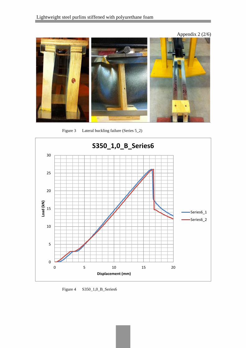
Lightweight steel purlins stiffened with polyurethane foam
Appendix 2 (2/6)
Figure 3 Lateral buckling failure (Series 5_2)
Figure 4 S350_1,0_B_Series6
0
5
10
15
20
25
30
0 5 10 15 20
Load
(kN
)
Displacement (mm)
S350_1,0_B_Series6
Series6_1
Series6_2

Lightweight steel purlins stiffened with polyurethane foam
Appendix 2 (3/6)
Figure 5 Local member buckling failure (Series 6_1)
Figure 6 Local member buckling failure (Series 6_2)
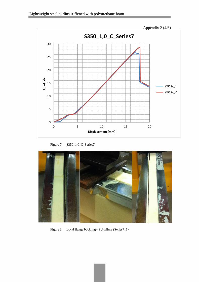
Lightweight steel purlins stiffened with polyurethane foam
Appendix 2 (4/6)
Figure 7 S350_1,0_C_Series7
Figure 8 Local flange buckling+ PU failure (Series7_1)
0
5
10
15
20
25
30
0 5 10 15 20
Load
(kN
)
Displacement (mm)
S350_1,0_C_Series7
Series7_1
Series7_2

Lightweight steel purlins stiffened with polyurethane foam
Appendix 2 (5/6)
Figure 9 Local flange buckling (Series 7_2)
Figure 10 S350_1,0_D_Series8
0
1
2
3
4
5
6
7
8
9
10
0 10 20 30 40 50 60
Load
(kN
)
Displacement (mm)
S350_1,0_D_Series8
Series8_1
Series8_2

Lightweight steel purlins stiffened with polyurethane foam
Appendix 2 (6/6)
Figure 11 Shear failure of PU-board (Series 8_1)
Figure 12 Shear failure of PU-board (Series 8_2)

Lightweight steel purlins stiffened with polyurethane foam
Appendix 3 (1/2)
INFORMATION OF THE USED GLUE DURING THE TEST SPECIMEN
MANUFACTURE

Lightweight steel purlins stiffened with polyurethane foam
Appendix 3 (2/2)

Lightweight steel purlins stiffened with polyurethane foam
Appendix 4 (1/11)
CALCULATION OF THE BENDING STIFFNESS FOR S350+Z275 C-PROFILE
Height of the profile
Height of the web only
Thickness of the web
Breadth of the profile
Breadth of flange only
Thickness of the flange
Length of the lip
Length of lip omitting thickness of flange
Thickness of the profile
Determination of Neutral axis:
Along x-axis
Along Y-axis
Now, calculating the Moment of Inertia for the given profile:
For two profiles,
h 200mm
hw 198mm
tw 1.0mm
b 50mm
bf 48mm
tf 1.0mm
c 20mm
cf 19mm
t 1.0mm
E 210000N
mm2
Atot t 2 c 2 bf h 336 mm2
x
t c( )c
2 bf tf
tf
2 h tw
h
2 tf bf h
tf
2
t c( ) hc
2
Atot
x 100mm
y
h tw tw
2 2 tf bf
b
2
2 tf c btf
2
Atot
y 13.333mm
I 2t cf
3
12t cf
h
2t
cf
2
2
2b tf
3
12b tf
h tf
2
2
tw h 2 tw 3
12
I 1.942 106
mm4
E I 407.911kN m2
2 E I 815.821kN m2
This is the bending stiffness value of S350+Z275 C-profile brutto cross-
section.

Lightweight steel purlins stiffened with polyurethane foam
Appendix 4 (2/11)
To calculate the maximum force a cold-formed C-purlin beam can take in a two point
load arrangement where forces are equidistant from each other and from the supports,
the total area of the cross-section that is bearing the stresses must be calculated first.
When a slender beam is loaded, it starts bending or buckling (depending on its cross-
sectional properties) well before it reaches its yield limit. Similarly, in case of cold-
formed sheet made purlins and beams, they behave the same way as slender beams as
the purlins have very low thickness compared to the span of the beam. But, cold-
formed purlins have a different characteristic on bending. When cold-formed purlins
are loaded horizontally (point load or uniformly distributed load), part of the beam that
is under pure tension (in our case the lower part of the beam comprising lower flange,
lower lip and half of the web) will distribute the tensile stress very evenly so that the
whole area of the tensile part of the beam (purlin) is effective. However in bending
load on the other hand, the compressive part of the beam which is the upper half of the
beam will have its ineffective parts that cannot contribute against the compressive
stresses. As we know, steel perform very poorly against compressive forces in compar-
ison to the very good performance against tensile forces. Also, in case of cold-formed
profiles, profiles under compression have different characteristic which can be illus-
trated by taking an example of C-purlin.
Here as we can see in the C-purlin given in the figure above, lower part of the web is
under pure tensile stress when loaded whereas the upper half of the profile is in pure
compression since the beam is loaded under bending. Sheet metal under tensile forces
is fully efficient and all the tensile part of the profile yields at its yield point. However,
under compressive stresses, sheet metal perform rather poorly as various buckling phe-
nomenon occur within the compressive zone of the profile. Profile web and profile
flanges are stiffened by their adjacent edges but not until the middle of the section (web
or flange). So when the profile is loaded in bending, web part and flanges under com-
pressive load starts buckling in various ways. Profile web on the compressive zone will
experience buckling load failure takes place when the buckling load is over the yield
limit. Compression flange in this case will experience buckling stress.

Lightweight steel purlins stiffened with polyurethane foam
Appendix 4 (3/11)
In our case, the upper part of the profile is in compressive stress comprising half of the
profile web, flange and upper lip of the profile. So, we need to calculate the amount of
area that is actually taking the compressive stress. For that we need to follow the Euro-
code EN1993-1-1.
Local buckling of compression elements is accounted for in EN 1993-1-3 primarily by
making reference to part 1.5 of the code. As explained in section 6.2.2 of this guide, an
effective width approach is adopted, whereby "ineffective" portions of the cross sec-
tions are omitted and section properties may be determined based on the remaining
effective portions. For cases where the maximum compressive stress in an element is
less than the yield stress (σ.com.Ed < fyb/γM0), different expressions for the reduction fac-
tor ρ to those supplied in part 1.5 should be adopted, as given by equations D13.2 and
D13.3:
When the cold-formed C-purlin is loaded under bending, the
tensile end of the profile is fully utilized under the tensile
stresses whereas the upper compressive part of the profile
experiences different buckling phenomenon. As the beam
gets flexure load, stresses distribute around the beam cross
section which is less than the yield point. As the flexural
loading increases, the compressive part of the beam initially
starts buckling locally and then distortional buckling. When
in local buckling, the edges or the lip of the profile prevents
the local displacements of the nodal points (i.e. at the flange-
to-lip junction). However, members like lips, flanges and web
are free to bend. So, the flanges bends inwards while web and
lips bend outwards like in the figure.
The test specimen manufactured was a simple C-purlin bent into the designed dimen-
sions without any longitudinal stiffeners. So, according to the Eurocode EN1993-1-5
...(4.4) Clause 4.1,
where,
Effective area under compression
Area under compression
Reduction factor of the original
width due to the
Ineffective parts in the cross sec-
tion
Ac.eff Ac
Ac.eff
Ac

Lightweight steel purlins stiffened with polyurethane foam
Appendix 4 (4/11)
First, we need to check effects of local buckling in the profile to know to what extent
the total area has reduced to the effective area that takes the compressive stress.
In our case, we have half the beam web, a flange and a lip in compression.
The beam web and flange are doubly supported by adjacent edges while the lip is sup-
ported only at one end hence being an outstand element.
The cross-section area for our profile under compression comprises of a 200mm high
web, 50 mm long flange and 20mm long strip of lip. So, we will isolate the profile
into each individual members compressed web, compressed flange and compressed
lip.
For the compressed web being an internal compression member meaning a doubly
supported compression element (element between two edge stiffeners), assuming
slenderness ratio as A,
for where
where,
Slenderness ratio of a plate for local buckling
The plate slenderness ratio is given by,
Ac.eff Ac
w
p 0.055 3 ( )
p2
w 1 A 0.673 3 ( ) 1
p

Lightweight steel purlins stiffened with polyurethane foam
Appendix 4 (5/11)
To calculate the exact action and resistance of the elements under bending, we should
subtract the thickness of the coating to the nominal thickness of the profile material.
Since our material is S350+Z275, S350 meaning the nominal yield strength of the steel
is 350N/mm2 and Z275 meaning there is 275g/m2 of zinc material distributed on each
side of the surface as coating. Converting the numerical value in terms of coating
thickness, we get 0.02mm. So, the new thickness of the profile is 1.0mm -
0.04mm=0.96mm
Nominal thickness of the profile
Reduced thickness of the profile due to the
zinc coated surface
So, our new thickness of profile for EWC is,
Determination of I-value of the C Profile:
Section properties for a 200 x 150 x 1.0 mm lipped C-profile:
Height of the profile
Height of the web only
Thickness of the web
Breadth of the profile
Breadth of flange only
Thickness of the flange
Length of the lip
Length of lip omitting thickness of flange
Thickness of the profile
Radius of curvature of the corners
Thickness of the coating per surface
When calculating the gross cross-sectional properties of
the profile, we should avoid the thickness of the coating
by subtracting it to the nominal thickness of the profile.
However, the contribution of the coating thickness to the
nominal thickness of the profile can be ignored.
Afy
cr
A
b1
t
28.4 k
tnom 1.0mm
tnet 0.96mm
h 200 mm
hw 198 mm
tw 1 mm
b 50mm
bf 48 mm
tf 1 mm
c 20 mm
cf 19mm
tnet 0.96mm
r 1.2mm
tcoating 0.02mm
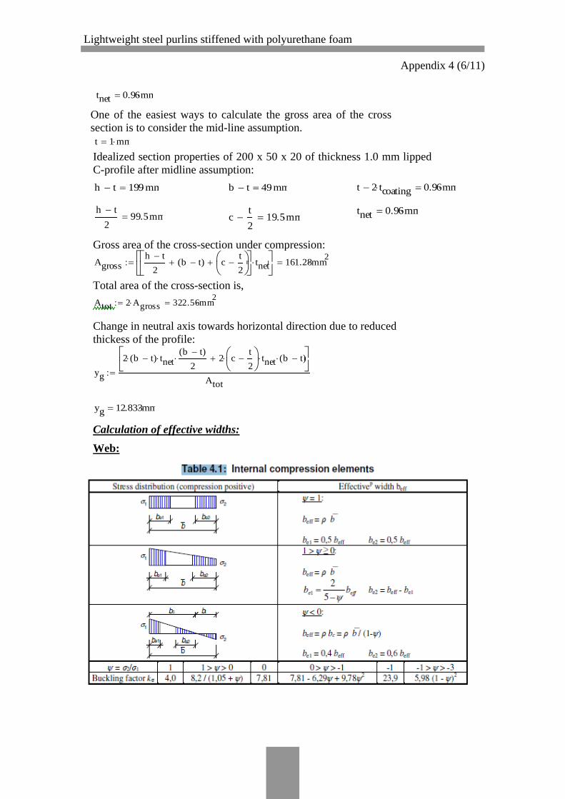
Lightweight steel purlins stiffened with polyurethane foam
Appendix 4 (6/11)
One of the easiest ways to calculate the gross area of the cross
section is to consider the mid-line assumption.
Idealized section properties of 200 x 50 x 20 of thickness 1.0 mm lipped
C-profile after midline assumption:
Gross area of the cross-section under compression:
Total area of the cross-section is,
Change in neutral axis towards horizontal direction due to reduced
thickess of the profile:
Calculation of effective widths:
Web:
tnet 0.96mm
t 1 mm
h t 199 mm b t 49mm t 2 tcoating 0.96mm
tnet 0.96mmh t
299.5mm c
t
2 19.5mm
Agrossh t
2b t( ) c
t
2
tnet
161.28mm2
Atot 2 Agross 322.56mm2
yg
2 b t( ) tnetb t( )
2 2 c
t
2
tnet b t( )
Atot
yg 12.833mm

Lightweight steel purlins stiffened with polyurethane foam
Appendix 4 (7/11)
Since our profile is in bending, the upper half of the beam goes under compression
whereas the lower half of the beam is in tensile force hence under full performance.
Since, the section of the profile is divided into two different stresses, we also half the
length of the web. Hence the new buckling length of the web under compression is
half the total length of the profile.
Value of σ2 is zero as we run towards neutral axis.
So, from EN 1993-1-5 Table 4.1
56 mm effective out of 99.5 mm.
Flange:
Uniform compressive stress
Uniform compressive stress
37.02mm effective out of 49mm. Flange
2
1
0 0 1
k 7.81 2
fy 350 MPa
235
fy
0.819
p
h t( )
2 tnet
28.4 k1.594 p 0 673 3 1
p 0.0553 ( )
p2
0.563 1
beff h t( )
2 55.969mm
WEB
kf 4.0
0.819
pf
b t( )
tnet
28.4 kf1.097 pf 0.748
f
pf 0.188
pf2
0.756 f 1.0
bf.eff f b t( ) 37.021mm

Lightweight steel purlins stiffened with polyurethane foam
Appendix 4 (8/11)
Lip:
For lip, we need to do an extra calculation of finding the stress
at the end of the lip in order to calculate the buckling factor
for lip.
If the material strength of the beam is 350 MPa and knowing
the dimensions of our profile, we can easily calculate stresses
in any place of the beam.
Stress at point B or at the end of lip, assume it is σ.b
Calculating the stress ratio,
fy 350MPa
emax 99.5mm
eb emax ct
2
80 mm
b
eb
emax
fy 281.407MPa
2
1
b
fy
0.804 0.802 1.0

Lightweight steel purlins stiffened with polyurethane foam
Appendix 4 (9/11)
From EN 1993-1-5 Table 4.2
11mm effective of 20 mm lip.
According to EN 1993-1-5 Table 4.1, in case of the web member under tensile and com-
pression the distribution of effective width is 40% to 60% where 40% zone being rela-
tively more compressed side of the profile.
So,
Now, we should calculate the effective section properties of the profile:
Calculation of effective area:
The horizontal position of the neutral axis from the centerline of the web for the effec-
tive section is,
k0.578
0.340.505 c
t
2 19.5mm
0.819lp
ct
2
tnet
28.4 k1.228
lp
p 0.188
p2
0.553
blpeff ct
2
10.969mm
be1 0.4beff 22.388mm be2 0.6beff 33.582mm
Aeff beff tnet bf.eff tnet blpeff tneth t
2
tnet b t( ) tnet ct
2
tnet
Aeff 261.081mm2
b t 49mm c 20 mm b t 49mm ct
2 19.5mm
yeff
ct
2
blpeff
b t( ) b t( ) bf.eff b t
2
tnet
Aeff
yeff 13.239mm

Lightweight steel purlins stiffened with polyurethane foam
Appendix 4 (10/11)
The vertical position of the neutral axis from the centerline of the lower flange for the
effective section is,
ct
2
21
2 h t( )
2 1
8 5.14 10
3 m
2
be2h t( )
2
be2
2
3.905 103
m2
be1 h t( )be1
2
4.205 103
m2
bf.eff h t( ) 7.367 103
m2
blpeff h t( )blpeff
2
2.123 103
m2
xeff
( ) tnet
Aeff
83.615mm
xeff 83.615mm
beff 55.969mm
be1 22.388mm be2 33.582mm bf.eff 37.021mm
blpeff 10.969mm

Lightweight steel purlins stiffened with polyurethane foam
Appendix 4 (11/11)
So the new moment of inertia of the C-profile only considering the effective cross-
section of the profile is,
For two profiles,
P
tnet ct
2
3
12c
t
2
tnet
xeff
ct
2
2
2
1.027 105
mm4
Qb t( ) tnet
3
12b t( ) tnet xeff
2 3.289 10
5 mm
4
Rtnet be2 99.5mm xeff
3
12be2 99.5mm xeff tnet
be2 99.5mm xeff
2
2
R 3.873 104
mm4
Stnet be1
3
12tnet be1 199.5mm xeff
be1
2
2
2.365 105
mm4
Tbf.eff tnet
3
12bf.eff tnet 199.5mm xeff
tnet
2
2
4.733 105
mm4
Utnet blpeff
3
12tnet blpeff 199.5mm xeff
blpeff
2
2
1.284 105
mm4
Vtnet xeff
3
12tnet xeff
xeff
2
2
1.871 105
mm4
Ieff P Q R S T U V 1.496 106
mm4
E 2.1 105
N
mm2
E Ieff 314.089kN m2
2 E Ieff 628.178kN m2
This is the bending stiffness value of S350+Z275 C-profile effective cross-
section.