Definition of Quality of Service parameters and their ... · PDF file4 VoLTE / ViLTE Quality...
75
GSM Association Non-confidential Official Document IR.42 - Definition of Quality of Service parameters and their computation V7.0 Page 1 of 75 Definition of Quality of Service parameters and their computation Version 7.0 17 October 2016 This is a Non-binding Permanent Reference Document of the GSMA Security Classification: Non-confidential Access to and distribution of this document is restricted to the persons permitted by the security classification. This document is confidential to the Association and is subject to copyright protection. This document is to be used only for the purposes for which it has been supplied and information contained in it must not be disclosed or in any other way made available, in whole or in part, to persons other than those permitted under the security classification without the prior written approval of the Association. Copyright Notice Copyright © 2016 GSM Association Disclaimer The GSM Association (“Association”) makes no representation, warranty or undertaking (express or implied) with respect to and does not accept any responsibility for, and hereby disclaims liability for the accuracy or completeness or timeliness of the information contained in this document. The information contained in this document may be subject to change without prior notice. Antitrust Notice The information contain herein is in full compliance with the GSM Association’s antitrust compliance policy.
Transcript of Definition of Quality of Service parameters and their ... · PDF file4 VoLTE / ViLTE Quality...

GSM Association Non-confidential
Official Document IR.42 - Definition of Quality of Service parameters and their computation
V7.0 Page 1 of 75
Definition of Quality of Service parameters and their computation
Version 7.0
17 October 2016
This is a Non-binding Permanent Reference Document of the GSMA
Security Classification: Non-confidential
Access to and distribution of this document is restricted to the persons permitted by the security classification. This document is confidential to the
Association and is subject to copyright protection. This document is to be used only for the purposes for which it has been supplied and
information contained in it must not be disclosed or in any other way made available, in whole or in part, to persons other than those permitted
under the security classification without the prior written approval of the Association.
Copyright Notice
Copyright © 2016 GSM Association
Disclaimer
The GSM Association (“Association”) makes no representation, warranty or undertaking (express or implied) with respect to and does not accept
any responsibility for, and hereby disclaims liability for the accuracy or completeness or timeliness of the information contained in this document.
The information contained in this document may be subject to change without prior notice.
Antitrust Notice
The information contain herein is in full compliance with the GSM Association’s antitrust compliance policy.

GSM Association Non-confidential
Official Document IR.42 - Definition of Quality of Service parameters and their computation
V7.0 Page 2 of 75
Table of Contents
1 Introduction 3
1.1 Scope of document 3
1.2 General considerations 4
1.3 Definition of Terms 5
1.4 Document Cross-References 6
2 QoS Parameters 8
2.1 QoS Parameters Model 8
2.2 Service-independent QoS parameters 9
2.3 Telephony Service 22
2.4 Short Message Service 31
2.5 Circuit Switched Data Service 35
2.6 Packet Switched Data Service (General Packet Radio Service) 36
2.7 Data Service Class Definitions and Measurements 41
2.8 FTP QoS Parameters 44
2.9 WEB Browsing (HTTP / HTTPS) QoS Parameters 48
2.10 PING QoS Parameters 52
3 QoS Parameters for Interconnection 53
3.1 ASR = (Answer Seizure Ratio) 53
3.2 ABR = (Answer BID Ratio) 53
3.3 CLI = (Calling Line Identification) 53
3.4 NER = (Network Efficiency Ratio) 54
3.5 PGAD = (Post Gateway Delay) 54
3.6 PDD = (Post Dial Delay) 54
3.7 ALOC = (Average Length of Conversation) 54
3.8 Speech Quality on Sample Basis. 54
4 VoLTE / ViLTE Quality Parameters 54
4.1 VoLTE / ViLTE Service Quality Parameters 55
4.2 VoLTE / ViLTE Networks & Transport QoS Parameters 63
Annex A Examples for measuring trigger points 73
A.1 SMS-Service: 73
A.1.1 Layer 3 Messages: 73
Annex B Document Management 74
B.1 Document History 74
B.2 Other Information 75
GSM Association Non-confidential
Official Document IR.42 - Definition of Quality of Service parameters and their computation
V7.0 Page 3 of 75
1 Introduction
1.1 Scope of document
This document defines quality of service (QoS) parameters and their computation. A QoS
parameter is also called quality Key Performance Indicator (KPI). Although the QoS
definitions themselves are generic the scope of this document underlines the roaming
deployment of those QoS parameters.
The parameter definition is split into two parts: the abstract definition and the generic
description of the measurement method with the respective trigger points.
Consistent use of the definitions in this document will allow independent parties to compare
QoS measurements and results. Figure 1 shows the relationship to the other QoS-related
PRDs.

GSM Association Non-confidential
Official Document IR.42 - Definition of Quality of Service parameters and their computation
V7.0 Page 4 of 75
IR.42
Computation
including trigger
point Dictionary
IR.81 GRQ
Measurement
implementation
BA.51
Roaming SLA
Handbook
AA.13
Roaming SLA
Annex C12
IR.78
Roaming
Trouble Report
IR.42
Computation
including trigger
point Dictionary
IR.81 GRQ
Measurement
implementation
BA.51
Roaming SLA
Handbook
AA.13
Roaming SLA
Annex C12
IR.78
Roaming
Trouble Report
Figure 1: Relationship between GSMA QoS documents
1.2 General considerations
All the defined QoS parameters and their computations are based on field measurements.
That indicates that the measurements were made from user’s point of view (full end-to-end
perspective, taking into account the needs of testing).
It is assumed that the mobile and the desired service can be operated correctly by the end
user, as operability is not evaluated in this document. For the purpose of measurement it is
assumed that:
the service is available and not barred for any reason;
routing is defined correctly without errors and;
the target subscriber equipment is ready to answer the call.
Only voice quality values measured for calls ended successfully must be used for statistical
analysis. However, measured values from calls ended unsuccessfully (for example, calls that
are dropped) should be available for additional evaluation if required, and therefore must be
stored. Further preconditions will apply when reasonable.

GSM Association Non-confidential
Official Document IR.42 - Definition of Quality of Service parameters and their computation
V7.0 Page 5 of 75
Monitoring of services using the parameters defined in this document could impact the traffic
and load on the networks involved, including the home public mobile network (HPMN), the
visited public mobile network (VPMN), and intermediary networks. Due consideration must
therefore be given to the monitoring regime to avoid unnecessary or adverse impacts on
these networks.
1.3 Definition of Terms
Term Meaning
APN Access Point Name
CS Circuit Switched
CSFB Circuit Switched Fall Back
DNS Domain Name System
EPC Evolved Packet Core
FTP File Transfer Protocol
GBR Guaranteed Bit Rate
HLR Home Location Register
HPMN Home Public Mobile Network
HSS Home Subscriber Server
HTTP Hypertext Transport Protocol
IMS Internet Protocol Multimedia Subsystem
IPX Internet Protocol Exchange
ISUP ISDN User Part
KPI Key Performance Indicator
LQO Listening Quality Objective
LTE Long Term Evolution (Radio)
MME Mobility Management Entity
MT Mobile Terminated
NER Network Efficiency Ratio
MS Mobile Station
MSC Mobile Switching Centre
OCN Original Called Number
PCEF Policy & Charging Enforcement Function
PCRF Policy & Charging Rule Function
P-CSCF Proxy - Call Session Control Function
PESQ Perceptual Evaluation of Speech Quality
PEVQ Perceptual Evaluation of Video Quality
PING Packet Internet Groper
POLQA Perceptual Objective Listening Quality Analysis
PRD Permanent Reference Document

GSM Association Non-confidential
Official Document IR.42 - Definition of Quality of Service parameters and their computation
V7.0 Page 6 of 75
Term Meaning
QCI QoS Class Indicator
QoS Quality of Service
RDN Redirecting Number
RTCP RTP Control Protocol
RTP Real-time Transport Protocol
SGSN Serving GPRS Support Node
SIP Session Initiation Protocol
SLA Service Level Agreement
SMS MO Mobile Originated SMS
SMS MT Mobile Terminated SMS
SMSoSGs SMS over SGs
SS7 Signalling System 7
SRVCC Single Radio Voice Call Continuity
ViLTE (conversational) Video over LTE
VoLTE Voice over Long Term Evolution
VPMN Visited Public Mobile Network
1.4 Document Cross-References
The following documents contain provisions which, through references in this text, constitute
provisions of the present document.
References are non-specific, i.e. refer to the latest version of the document.
No. Document Description
[1] ETSI TS 102 250-3 "Speech Processing, Transmission and Quality Aspects (STQ); QoS aspects for popular services in GSM and 3G networks; Part 3: Typical procedures for Quality of Service measurement equipment".
[2] ETSI TS 102 250-2 "Speech Processing, Transmission and Quality Aspects (STQ); QoS aspects for popular services in GSM and 3G networks; Part 2: Definition of Quality of Service parameters and their computation ".
[3] GSMA PRD IR.88 LTE and EPC Roaming Guidelines
[4] ITU-T-E.437 “Comparative metrics for network performance Management”
[5] ETSI EN 300 089 "Integrated Services Digital Network (ISDN); Calling Line Identification Presentation (CLIP) supplementary service; Service description".
[6] ITU-T-Y.1540 “IP packet transfer and availability performance parameters”; IPLR – IP Packet Loss Ratio
[7] 3GPP TS 29.002 ”Mobile Application Part (MAP) specification”
[8] 3GPP TS 29.060 ”General Packet Radio Service (GPRS); GPRS Tunnelling Protocol (GTP) across the Gn and Gp interface”
[9] 3GPP TS 24 008 "Mobile radio interface Layer 3 specification; Core network

GSM Association Non-confidential
Official Document IR.42 - Definition of Quality of Service parameters and their computation
V7.0 Page 7 of 75
No. Document Description
protocols; Stage 3".
[10] IETF RFC 2647 ”Benchmarking Terminology for Firewall Performance; 3.1.7 Goodput”
[11] GSMA PRD IR.34 GSMA Inter-Service Provider IP Backbone Guidelines
[12] ITU-T-E.800 “Terms and Definitions Related to Quality of Service and Network Performance Including Dependability - Telephone Network and ISDN Quality of Service, Network Management and Traffic Engineering (Study Group II)”
[13] ITU-T E.431 “Service Quality Assessment for Connection Set-up and Release Delays (Study Group II)”
[14] ITU-T E.425 “Internal Automatic Observations Series E: Overall Network Operation, Telephone Service, Service Operation and Human Factors Network Management - Checking the Quality of the International Phone Service”
[15] GSMA PRD BA.51 “Roaming Service Level Agreement Guidelines”
[16] ITU-T QE.850 “Usage of cause and location in the digital subscriber signalling system No. 1 and the signalling system No. 7 ISDN user part”
[17] ITU-T Q.732.2 “Stage 3 Description for Call Offering Supplementary Services Using Signalling System No.7: Call Diversion Services: - Call Forwarding Busy - Call Forwarding No Reply - Call Forwarding Unconditional - Call Deflection - Series Q: Switching and Signalling - Specifications of Signalling System No.7 - ISDN Supplementary Services”
[18] GSMA PRD IR.25 VoLTE Roaming Testing
[19] GSMA PRD IN.21 “GSM Association Roaming Database, Structure and Updating Procedures”
[20] 3GPP TS 29.272 MME and SGSN related interfaces based on Diameter protocol
[21] ITU-T P.862 Perceptual evaluation of speech quality (PESQ): An objective method for end-to-end speech quality assessment of narrow-band telephone networks and speech codecs
[22] GSMA PRD AA.13 “International Roaming Agreements – Common Annexes
[23] GSMA PRD IR.78 “Roaming Trouble Report”
[24] 3GPP TS 45.008 Radio subsystem link control
[25] 3GPP TS 25.304 UE procedures in idle mode and procedures for cell reselection in connected mode
[26] 3GPP TS 36.304 EUTRA; UE procedures in idle mode
[27] ITU-T P.863 Perceptual Objective Listening Quality Assessment (POLQA)
[28] ETSI TR 102 506 Estimating Speech Quality per Call
[29] ITU-T P.862.1 Perceptual evaluation of speech quality (PESQ): Mapping function for transforming P.862 raw result scores to MOS-LQO
[30] GSMA PRD IR.65 IMS Roaming & Interworking Guidelines
[31] GSMA PRD IR.92 IMS Profile for Voice and SMS
[32] GSMA PRD IR.94 IMS Profile for Conversational Video Service
[33] GSMA PRD NG.103
VoLTE-RCS Roaming and Interconnection Guidelines
GSM Association Non-confidential
Official Document IR.42 - Definition of Quality of Service parameters and their computation
V7.0 Page 8 of 75
No. Document Description
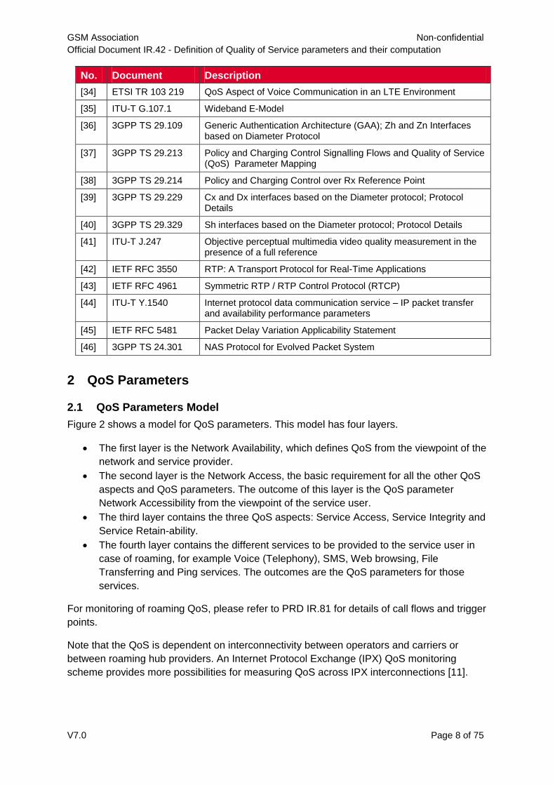
[34] ETSI TR 103 219 QoS Aspect of Voice Communication in an LTE Environment
[35] ITU-T G.107.1 Wideband E-Model
[36] 3GPP TS 29.109 Generic Authentication Architecture (GAA); Zh and Zn Interfaces based on Diameter Protocol
[37] 3GPP TS 29.213 Policy and Charging Control Signalling Flows and Quality of Service (QoS) Parameter Mapping
[38] 3GPP TS 29.214 Policy and Charging Control over Rx Reference Point
[39] 3GPP TS 29.229 Cx and Dx interfaces based on the Diameter protocol; Protocol Details
[40] 3GPP TS 29.329 Sh interfaces based on the Diameter protocol; Protocol Details
[41] ITU-T J.247 Objective perceptual multimedia video quality measurement in the presence of a full reference
[42] IETF RFC 3550 RTP: A Transport Protocol for Real-Time Applications
[43] IETF RFC 4961 Symmetric RTP / RTP Control Protocol (RTCP)
[44] ITU-T Y.1540 Internet protocol data communication service – IP packet transfer and availability performance parameters
[45] IETF RFC 5481 Packet Delay Variation Applicability Statement
[46] 3GPP TS 24.301 NAS Protocol for Evolved Packet System
2 QoS Parameters
2.1 QoS Parameters Model
Figure 2 shows a model for QoS parameters. This model has four layers.
The first layer is the Network Availability, which defines QoS from the viewpoint of the
network and service provider.
The second layer is the Network Access, the basic requirement for all the other QoS
aspects and QoS parameters. The outcome of this layer is the QoS parameter
Network Accessibility from the viewpoint of the service user.
The third layer contains the three QoS aspects: Service Access, Service Integrity and
Service Retain-ability.
The fourth layer contains the different services to be provided to the service user in
case of roaming, for example Voice (Telephony), SMS, Web browsing, File
Transferring and Ping services. The outcomes are the QoS parameters for those
services.
For monitoring of roaming QoS, please refer to PRD IR.81 for details of call flows and trigger
points.
Note that the QoS is dependent on interconnectivity between operators and carriers or
between roaming hub providers. An Internet Protocol Exchange (IPX) QoS monitoring
scheme provides more possibilities for measuring QoS across IPX interconnections [11].

GSM Association Non-confidential
Official Document IR.42 - Definition of Quality of Service parameters and their computation
V7.0 Page 9 of 75
Figure 2: Four Layer model for QoS Parameters.
2.2 Service-independent QoS parameters
The service-independent QoS parameters characterise network availability, network
accessibility, IP connectivity and bearer context cut-off. The parameters are therefore
considered as technology-dependent. Table 1 provides an overview.

GSM Association Non-confidential
Official Document IR.42 - Definition of Quality of Service parameters and their computation
V7.0 Page 10 of 75
Technologies
2G / 3G 4G VoLTE/ViLTE Future
technology
Network /service
availability
Scan for PLMN:
Radio network
availability
Scan for PLMN:
Radio network
availability
EPS Network
feature support:
IMS voice / video
over PS session
in S1 mode
supported
FFS
Network / service
accessibility
CS and/or PS
attach:
Network selection
and registration
successful ratio
/time
LTE attach (EPS
or EPS+IMSI):
Network selection
and registration
successful ratio
/time
IMS Registration
success ratio
/time
IP connectivity (Primary) PDP
context
activation:
PDP context
activation
successful ratio
/time
Default /
Dedicated EPS
bearer context
activation:
Default EPS
bearer context
activation
successful ratio
/time
QCI 5 default EPS bearer context activation for the IMS well-known APN connection;
QCI 1 dedicated EPS bearer context activation for voice media;
Default /
dedicated EPS
bearer context
activation
success ratio
/time
Network / service
retainability
PDP context
dropped:
PDP context cut-
off ratio
Default EPS
bearer context
dropped:
Default EPS
bearer context
cut-off ratio
QCI 5 default /
QCI 1 dedicated
EPS bearer
context cut-off
ratio
Table 1: Overview of QoS parameters on technology-dependency
For 2G/ 3G (i.e. GSM/GPRS and UMTS) networks it is necessary to establish a data
connection before the possibility of accessing a service. In LTE networks the concept of IP
connectivity “always on” has been established. It allows a faster access to the services of a
mobile network by state changes on request of a user or application. The impact of this
concept on the QoS parameters is that they cannot be triggered explicitly anymore as they
require a specific service request. Nevertheless the defined QoS parameters remain valid
and can be derived from the trigger points given.
This section contains also DNS KPI. DNS service is an intermediate internet service used by
the other specific PS data services such as FTP or HTTP. However, the DNS service is

GSM Association Non-confidential
Official Document IR.42 - Definition of Quality of Service parameters and their computation
V7.0 Page 11 of 75
independent from those specific data services. Network Accessibility Circuit Switched (NA –
CS) [1] [12].
Please refer to PRD IR.81 for details of call flow and trigger points.
2.2.1 Network Availability [2] [12]
2.2.1.1 Abstract definition
Probability that the Mobile Services are offered to a user.
See ITU-T Rec. E.800: The probability that the user of a service after a request receives the
proceed-to-select signal within specified conditions.
See complementary QoS parameter RNU in ETSI TS 102 250-2 (5.1 Radio Network
Unavailability).
2.2.1.2 Computation
Trigger points:
2.2.1.2.1GSM: C1-Criteria > 0 [24]
GPRS: broadcasting GPRS indicator in system information 3 or system information 4
UMTS (WCDMA) [25], LTE [26]: S Criteria fulfilled
Any emergency camping on any other than the target networks is considered as no network.
The target networks could constitute more than one network, for example to cover national
or international roaming or via a roaming hub.
When the mobile equipment supports multi-mode (GSM/UMTS/LTE),the judgement on
Radio Network Availability is made with respect to the radio access technology under the
test aspect.
For CSFB and SMSoSGs, LTE S criteria is applied.
Abstract formula:
2.2.1.2.2
100 attempts probing all
available services mobile with attempts probing[%]ty AvailabiliNetwork Radio
2.2.2 Network Accessibility [2]
2.2.2.1 Abstract definition
Probability that the user performs a successful selection and registration on the desired
PLMN (manual selection mode, automatic selection mode with a defined desired PLMN) or
on a certain PLMN (automatic selection mode without a defined desired PLMN).
See ETSI 102 250-2 (5.2.1 Network Selection and Registration Failure Ratio).

GSM Association Non-confidential
Official Document IR.42 - Definition of Quality of Service parameters and their computation
V7.0 Page 12 of 75
2.2.2.2 Computation
2.2.2.3 Trigger points:
Initiate manually or automatically PLMN selection, stop measurement after successful
registration.
Abstract formula:
2.2.2.3.1
100 attemptson registrati andselection all
PLMNon attempson registrati andselection successful
[%] Ratio Successon Registrati andSelection Network Automatic} | {Manual NA[%]
NA-CS[%] is applied to GSM or UMTS-CS. NA-PS[%] is applied to GPRS, UMTS-PS, LTE,
respectively.
2.2.3 Circuit Switched LU Success Ratio (CS LU – SR) [2]
2.2.3.1 Abstract definition
The CSLU success ratio describes the probability that a subscriber can successfully attach
to the CS network.
See ETSI 102 250-1 (5.2 Network non-accessibility).
2.2.3.2 Computation
See ETSI TS 102 250-2 (5.2 Network non-accessibility).
Abstract formula: 2.2.3.2.1
Trigger points:
2.2.3.2.2
Start: Mobile sends the CS attach request message.
Stop: Mobile receives the CS attach accept message.
Remarks
2.2.3.2.3
Success ratio measurements will depend on whether the LU is the very first LU attempt or
one of subsequent attempts. (See remarks for CSLU-D below).
2.2.4 Circuit Switched Location Update Delay (CS LU - D)
2.2.4.1 Abstract definition
This CSLU delay describes the time period needed to attach to the CS network.
%100xptsttachAttemTotalNrCSA
AttemptsulCSAttachNrSuccessfsRatioCSLUSucces

GSM Association Non-confidential
Official Document IR.42 - Definition of Quality of Service parameters and their computation
V7.0 Page 13 of 75
2.2.4.2 Computation
Abstract formula:
2.2.4.2.1
Trigger points:
2.2.4.2.2
(for the computation of the unit CSLU delay):
Start: Point of time when the mobile sends the attach request message.
Stop: Point of time when the mobile receives the attach accept message.
Remarks:
2.2.4.2.3The difference between an attach of a known subscriber and an unknown subscriber will be
reflected in the time period indicating the attach setup time. In case of an unknown
subscriber (meaning that the Mobile Switching Centre (MSC) has changed since the detach,
or if it is the very first attach of the mobile to the network), the MSC contacts the Home
Location Register (HLR) in order to receive the subscriber data. The attach setup time of an
unknown subscriber will be slightly longer than the one of a known subscriber.
While determining the average attach setup time only successful attach attempts are
included in the calculations.
2.2.5 Packet Switched LU Success Ratio (PS LU - SR)1 [2] [7]
2.2.5.1 Abstract definition
The PSLU success ratio describes the probability of a subscriber to successfully attach to
the PS network.
See ETSI TS 102 250-2 (5.3 Attach Failure Ratio)
1 The KPI Packet-Switched Location Update was named originally from the
MAP_Update_GPRS_Location procedure, as described in 3GPP TS 29.002 [7]. It is used for the PS
attach, i.e. for GPRS attach. The same term Location is also used in the Location Management
procedure in 3GPP 29.272 [20] for Update Location and Cancel Location at S6a, i.e. EPS attach.
AttemptsulCSAttachNrSuccessf
ttSumCSLUDelay
artCSAttachStmpleteCSAttachCo )(

GSM Association Non-confidential
Official Document IR.42 - Definition of Quality of Service parameters and their computation
V7.0 Page 14 of 75
2.2.5.2 Computation 4
Abstract formula:
2.2.5.2.1
Trigger points:
2.2.5.2.2
Start: Mobile sends the PS attach request message
Stop: Mobile receives the PS attach accept message.
Remarks
2.2.5.2.3Depending upon the technologies, PS attach is understood as either a GPRS attach, or an
EPS attach.
A combined EPS + IMSI attach is applied to CSFB or SMSoSGs.
2.2.6 Packet Switched Location Update Delay (PS LU - D) [2]
2.2.6.1 Abstract definition
This PSLU delay describes the time period needed to attach to the PS network.
See ETSI TS 102 250-2 (5.4 Attach Setup Time)
2.2.6.2 Computation
Abstract formula: 2.2.6.2.1
Trigger points:
2.2.6.2.2
Start: Point of time when the mobile sends the attach
request message
Stop: Point of time when the mobile receives the attach
accept message.
Remarks:
2.2.6.2.3
The difference between an attach of a known subscriber and an unknown subscriber will be
reflected in the time period indicating the attach setup time. In case of an unknown
subscriber (meaning that the SGSN, S4 SGSN or MME has been changed since the detach,
or if it is the very first attach of the mobile to the network), the SGSN contacts the HLR, the
S4 SGSN contacts HSS or the MME contacts HSS respectively, in order to receive the
%100xptsttachAttemTotalNrPSA
AttemptsulPSAttachNrSuccessfsRatioPSLUSucces
AttemptsulPSAttachNrSuccessf
ttSumPSLUDelay
artPSAttachStmpletePSAttachCo )(

GSM Association Non-confidential
Official Document IR.42 - Definition of Quality of Service parameters and their computation
V7.0 Page 15 of 75
subscriber data. The attach setup time of an unknown subscriber will be slightly longer than
the one of a known subscriber.
2.2.7 PDP Context Activation Success Ratio (SA PSD) [2] [19]
2.2.7.1 Abstract definition
A packet-switch data session will be considered set-up successfully if a PDP Context can be
successfully activated.
See ETSI TS 102 250-2 (5.5 PDP Context Activation Failure Ratio)
2.2.7.2 Computation
Abstract formula:
2.2.7.2.1
Any PDP Context Activation request is considered as an attempt.
Trigger points: 2.2.7.2.2
PDP Context Activations are considered successful upon the reception of notifications of
successful PDP context activation (Activate PDP Context Accept).
Remarks: 2.2.7.2.3
It is recommended to use a limited and defined list of APNs for consistent measurements.
Operators are encouraged to maintain a list of standard APNs for measurements in PRD
IR.21 (or alternatively defined in roaming service level agreements (SLAs)). The list could
include APNs for MMS, WAP and/or internet, both pre-paid and post-paid. The APNs should
be defined as part of test conditions.
LTE: see Default EPS Bearer Context Activation Success Ratio
2.2.8 PDP Context Activation Time [2] [19]
2.2.8.1 Abstract definition
Is time between sending the PDP Context Activation request and receiving the notification of
successful completion of that activation.
See ETSI TS 102 250-2 (5.6 PDP Context Activation Time)
2.2.8.2 Computation
Abstract formula:
2.2.8.2.1
[s] t- t=[s] Time ActivationContext PDP request activationcontext PDPaccept activationcontext PDP
emptsivationAttContextActNrOfAllPDP
ssfultionsSuccetextActivaNrOfPDPConeSuccessRatActivationPDPContext %100

GSM Association Non-confidential
Official Document IR.42 - Definition of Quality of Service parameters and their computation
V7.0 Page 16 of 75
Trigger points:
2.2.8.2.2
Start: Sending of the PDP Context Activation request
End: Reception of the notification of successful PDP
context activation (Activate PDP Context Accept)
Remarks: 5 When averaging the PDP Context Activation Time, only the successful activations should be
considered.
It is recommended to use a limited and defined list of APNs for consistent measurements.
Operators are encouraged to maintain a list of standard APNs for measurements in PRD
IR.21 (or alternatively defined in Roaming SLAs). The list could include APNs for MMS, WAP
and/or internet, both pre-paid and post-paid. The APNs should be defined as part of test
conditions.
User activation (GPRS PDP context creation procedure) is recommended as network
activation tends to be for local services (home usage).
LTE: See Default EPS Bearer Context Activation Time or additional Default EPS Bearer
Context Activation Time
2.2.9 PDP Context Cut-Off Ratio [2] [8]
2.2.9.1 Abstract definition
The PDP context cut-off ratio denotes the probability that a PDP context is deactivated
without being deactivated intentionally by the user.
ETSI TS 102 250-2 (5.7 PDP Context Cut-off Ratio).
See also 3GPP TS 29.060.
2.2.9.2 Computation
Abstract formula:
2.2.9.2.1
Trigger points:
2.2.9.2.2
Different trigger points for a PDP context deactivation not initiated intentionally by the user
are possible: SGSN failure or GGSN failure on which the PDP context will be deactivated by
the SGSN or GGSN. The UE receives from the network the message DEACTIVATE PDP
CONTEXT REQUEST, MODIFY PDP CONTEXT REQUEST or DETACH REQUEST.
Remarks:
2.2.9.2.3
When analysing how to practically measure this parameter, a key point will be to identify how
to assess whether a PDP context loss has been initiated by the user or not. Active and
passive monitoring methods might adopt different approaches for that. In the active
PContextsctivatedPDcessfullyANrOfAllSuc
redByTheUseNotInitiattextLossesNrOfPDPConoCutOffRatiPDPContext %100

GSM Association Non-confidential
Official Document IR.42 - Definition of Quality of Service parameters and their computation
V7.0 Page 17 of 75
monitoring case, the test case specifies when the PDP context should be deactivated and
any loss prior to that can thus (generally) be considered as ‘not initiated by the user’. In the
passive monitoring case, the use of PDP context failure codes can be used.
A precondition for measuring this parameter is that a PDP context is successfully
established first.
2.2.10 Default EPS Bearer Context Activation Success Ratio [2] [3]
2.2.10.1 Abstract definition
Default EPS bearer context for the default APN: success of the EPS attach procedure (PS LU-SR)
In case of an additional default EPS bearer context: success of activation of the additional
default EPS bearer context
See ETSI TS 102 250-2 (5.12.1 Default EPS Bearer Context Activation Failure Ratio)
2.2.10.2 Computation
Abstract formula: 2.2.10.2.1Default EPS bearer context activation success ratio for the default APN: same as EPS
attach success ratio (PS LU-SR).
Additional default EPS bearer context, referring to an APN different from the default one:
100 sinitiation connection PDN additional
successesent establishm connection PDN additional
[%] Ratio Success ActivationContext Bearer EPSDefault Additional
Any additional Default Context Activation request is considered as an initiation.
Trigger points:
2.2.10.2.2
The trigger points for the default EPS bearer context referring to the default APN is same as
EPS attach procedure.
PDN Connectivity Request for additional default EPS bearer Context Activations is sent by the UE. The additional PDN connectivity is considered successful upon the reception of notifications of additional default EPS bearer context activation (Activate default EPS bearer Context Request)
Remarks:
2.2.10.2.3
It is recommended to use a limited and defined list of APNs for consistent measurements.
Operators are encouraged to maintain a list of standard APNs for measurements in PRD
IR.21 (or alternatively defined in roaming service level agreements (SLAs)). The list could
include APNs for MMS, WAP and/or internet, both pre-paid and post-paid. The APNs should
be defined as part of test conditions.

GSM Association Non-confidential
Official Document IR.42 - Definition of Quality of Service parameters and their computation
V7.0 Page 18 of 75
When the UE is powered on it will perform an EPS attach which includes the registration with
the network and the setup of a default EPS bearer context for the default APN. A default
EPS bearer context is successfully established when (EPS) ATTACH COMPLETE is sent by
the UE. This context replaces the primary PDP context defined for 2G/3G networks.
2.2.11 Default EPS Bearer Context Activation Time [2]
2.2.11.1 Abstract definition
The default EPS bearer context activation time is the time period needed to establish the
initial default EPS bearer context for the default APN or any additional PDN connection (i.e.
any additional default EPS bearer context), respectively.
See ETSI TS 102 250-2 (5.12.2 Default EPS Bearer Context Activation Time)
2.2.11.2 Computation
Abstract formula:
2.2.11.2.1Default EPS bearer context for the default APN2:
[s] t- t=[s] Time ActivationContext Bearer EPSDefault requestattach completeattach
Additional default EPS bearer context:
[s] t- t
=[s] Time ActivationContext Bearer EPS Default Additional
initiation connection PDN Additionalentestablishm connection PDN Additional
Trigger points: 2.2.11.2.2
PDN CONNECTIVITY REQUEST for additional default EPS bearer Context Activations is
sent by the UE. The ACTIVATE DEFAULT EPS BEARER CONTEXT ACCEPT is sent by
the UE.
Remarks:
2.2.11.2.3
Precondition: Successful default PDN connection for the default APN is prior to the
additional default PDN connections.
2 The PDN CONNECTIVITY REQUEST message is piggybacked in ATTACH REQUEST. The ACTIVATE
DEFAULT EPS BEARER CONTEXT REQUEST message is piggybacked in ATTACH ACCEPT. The ACTIVATE
DEFAULT EPS BEARER CONTEXT ACCEPT message is piggybacked in ATTACH COMPLETE.
GSM Association Non-confidential
Official Document IR.42 - Definition of Quality of Service parameters and their computation
V7.0 Page 19 of 75
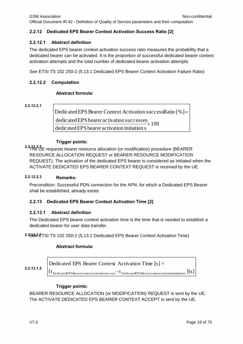
2.2.12 Dedicated EPS Bearer Context Activation Success Ratio [2]
2.2.12.1 Abstract definition
The dedicated EPS bearer context activation success ratio measures the probability that a
dedicated bearer can be activated. It is the proportion of successful dedicated bearer context
activation attempts and the total number of dedicated bearer activation attempts.
See ETSI TS 102 250-2 (5.13.1 Dedicated EPS Bearer Context Activation Failure Ratio)
2.2.12.2 Computation
Abstract formula:
2.2.12.2.1
100 sinitiation activationbearer EPS dedicated
successes activationbearer EPS dedicated
[%] Ratio success ActivationContext Bearer EPS Dedicated
Trigger points: 2.2.12.2.2
The UE requests bearer resource allocation (or modification) procedure (BEARER
RESOURCE ALLOCATION REQUEST or BEARER RESOURCE MODIFICATION
REQUEST). The activation of the dedicated EPS bearer is considered as initiated when the
ACTIVATE DEDICATED EPS BEARER CONTEXT REQUEST is received by the UE.
Remarks: 2.2.12.2.3
Precondition: Successful PDN connection for the APN, for which a Dedicated EPS Bearer
shall be established, already exists
2.2.13 Dedicated EPS Bearer Context Activation Time [2]
2.2.13.1 Abstract definition
The Dedicated EPS bearer context activation time is the time that is needed to establish a
dedicated bearer for user data transfer.
See ETSI TS 102 250-2 (5.13.2 Dedicated EPS Bearer Context Activation Time)
Abstract formula:
2.2.13.1.1
[s] t- t
=[s] Time ActivationContext Bearer EPS Dedicated
initiation activationcontext Bearer EPS Dedicatedsuccess activationcontext Bearer EPS Dedicated
Trigger points:
2.2.13.1.2
BEARER RESOURCE ALLOCATION (or MODIFICATION) REQUEST is sent by the UE.
The ACTIVATE DEDICATED EPS BEARER CONTEXT ACCEPT is sent by the UE.

GSM Association Non-confidential
Official Document IR.42 - Definition of Quality of Service parameters and their computation
V7.0 Page 20 of 75
Remarks:
2.2.13.1.3
The dedicated EPS bearer context activation procedure is triggered by the UE for bearer
resource allocation and completed when the allocated dedicated EPS bearer context is
accepted by the UE.
2.2.14 EPS Bearer Context Cut-off Ratio [%] [2]
2.2.14.1 Abstract Definition
The default or dedicated EPS bearer context cut-off ratio measures whether a default or a
dedicated EPS bearer context is deactivated without being initiated intentionally by the user3.
See ETSI TS 102 250-2 (5.12.3 Default EPS Bearer Context Cut-off ratio, 5.13.3 Dedicated
EPS Bearer Context Cut-off ratio)
2.2.14.2 Computation
Abstract Formula
2.2.14.2.1
100contextsbearer EPS dedicated |default activatedly successful
user by the initiatednot lossescontext bearer EPS dedicated |default
=[%] Ratio off-CutContext Bearer EPS Dedicated |Default
Trigger Points 2.2.14.2.2
Different trigger points for a EPS bearer context deactivation not initiated intentionally by the
user are possible. The EPS bearer context will be deactivated by the network. The UE
receives from the network the message DEACTIVATE EPS BEARER CONTEXT
REQUEST, MODIFY EPS BEARER CONTEXT REQUEST or DETACH REQUEST.
Remarks 2.2.14.2.3
Default EPS bearer context (for the default APN) loss means UE EPS detach.
2.2.15 DNS Host Name Resolution Success Ratio [%] [2]
2.2.15.1 Abstract Definition
The DNS host name resolution success ratio is the probability for a host name to host
address translation of a DNS resolver is successful.
See ETSI TS 102 250-2 (5.10 DNS Host Name Resolution Failure Ratio)
3 The default EPS bearer context for the default APN is indispensable to be maintained to use any
service over LTE networks or any additional default EPS bearer context. Deactivating the last default
EPS bearer will cause the UE detach.

GSM Association Non-confidential
Official Document IR.42 - Definition of Quality of Service parameters and their computation
V7.0 Page 21 of 75
2.2.15.2 Computation
Abstract Formula
2.2.15.2.1 100requests resolution namehost DNS
requests resolution namehost DNS successful
[%] Ratio Success Resolution NameHost DNS
Trigger points
2.2.15.2.2
Start: Request to resolve a host address from DNS server, or DNS protocol data packet
containing DNS type A (host address) “Standard query” query for the desired host name.
Stop: Host address received from DNS server, or DNS protocol data packet received
containing a type A (host address) “Standard query response, No error” response, the
respective type A “Standard query” query and an answer including the desired host name to
host address translation.
Remarks
2.2.15.2.3Precondition for measurement:
The resolver shall not have direct access to any local DNS name server or any name
server’s zone.
Since messages carried by UDP are restricted to 512 bytes. UDP is the recommended
method for standard queries on the Internet.
The KPI is relevant only for PS services.
2.2.16 DNS Host Name Resolution Time [s] [2]
2.2.16.1 Abstract Definition
The DNS host name resolution time is the time it takes a host name to host address
translation.
See ETSI TS 102 250-2 (5.11 DNS Host Name Resolution Time)
2.2.16.2 Computation
The DNS host name resolution time is the time it takes a host name to host address
translation.
Abstract Formula
2.2.16.2.1
[s] t- t=[s] Time Resolution NameHost DNS eryStandardQueery ResponsStandardQu
Trigger points
2.2.16.2.2
Start: Request to resolve a host address from DNS server, or DNS protocol data packet
containing DNS type A (host address) “Standard query” query for the desired host name

GSM Association Non-confidential
Official Document IR.42 - Definition of Quality of Service parameters and their computation
V7.0 Page 22 of 75
Stop: Host address received from DNS server, or DNS protocol data packet received
containing a type A (host address) “Standard query response, No error” response, the
respective type A “Standard query” query and an answer including the desired host name to
host address translation.
Remarks
2.2.16.2.3
Precondition for measurement:
The resolver shall not have direct access to any local DNS name server or any name
server’s zone.
For static measurement methodologies, as defined in TS 102 250-3 [1], the queried DNS
name server shall have any data related to the host name to be resolved available as
authoritative data in one of the name server’s zones, so that no recursive lookups have to be
performed and no use of cached information will be required.
If the related data is not stored locally in the name server’s zone, the resolution time would
vary due to DNS caching strategies
The KPI is relevant only for PS services.
2.3 Telephony Service
To simplify the description of the voice call KPIs, R-party and H-party are used in the context
where R-party is the roaming side in VPMN and H-party is in HPMN.
A precondition for the applicability of this section to the voice CSFB:
The LTE networks (VPMN) support voice CSFB. The UE (represented by R-party) are
configured as voice centric and CS voice only or CS voice preferred, IMS PS Voice as
secondary.
2.3.1 Service Accessibility Telephony - MO (SA-T-MO) [2] [12] [14]
2.3.1.1 Abstract definition
Probability that the end-user can access the Mobile Telephony Service when requested if it
is offered by display of the network indicator on the Mobile Equipment.
See ITU-T Rec. E.800: The probability that a service can be obtained within specified
tolerances and other given operating conditions when requested by the user. The term NER
(Network Effectiveness Ratio defined in ITU-E 425) is understood as Service Accessibility
Telephony.
See complementary Service Non-Accessibility Telephony (SNAT) in ETSI TS 102 250-2
(6.6.1 Service non-accessibility).
2.3.1.2 Computation
For a successful call attempt:
CS, CSFB
The user hears the alerting tone, or R-party receives ALERTING
GSM Association Non-confidential
Official Document IR.42 - Definition of Quality of Service parameters and their computation
V7.0 Page 23 of 75
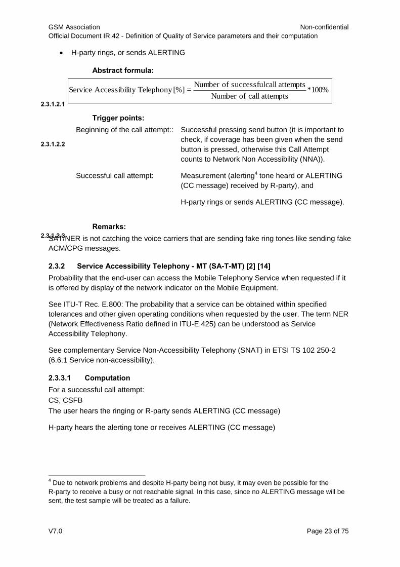
H-party rings, or sends ALERTING
Abstract formula:
2.3.1.2.1
Trigger points:
2.3.1.2.2
Beginning of the call attempt:: Successful pressing send button (it is important to
check, if coverage has been given when the send
button is pressed, otherwise this Call Attempt
counts to Network Non Accessibility (NNA)).
Successful call attempt: Measurement (alerting4 tone heard or ALERTING
(CC message) received by R-party), and
H-party rings or sends ALERTING (CC message).
Remarks: 2.3.1.2.3SAT/NER is not catching the voice carriers that are sending fake ring tones like sending fake
ACM/CPG messages.
2.3.2 Service Accessibility Telephony - MT (SA-T-MT) [2] [14]
Probability that the end-user can access the Mobile Telephony Service when requested if it
is offered by display of the network indicator on the Mobile Equipment.
See ITU-T Rec. E.800: The probability that a service can be obtained within specified
tolerances and other given operating conditions when requested by the user. The term NER
(Network Effectiveness Ratio defined in ITU-E 425) can be understood as Service
Accessibility Telephony.
See complementary Service Non-Accessibility Telephony (SNAT) in ETSI TS 102 250-2
(6.6.1 Service non-accessibility).
2.3.3.1 Computation
For a successful call attempt:
CS, CSFB
The user hears the ringing or R-party sends ALERTING (CC message)
H-party hears the alerting tone or receives ALERTING (CC message)
4 Due to network problems and despite H-party being not busy, it may even be possible for the
R-party to receive a busy or not reachable signal. In this case, since no ALERTING message will be
sent, the test sample will be treated as a failure.
100%*attempts call ofNumber
attempts call successful ofNumber =[%]Telephony ity Accessibil Service

GSM Association Non-confidential
Official Document IR.42 - Definition of Quality of Service parameters and their computation
V7.0 Page 24 of 75
Abstract formula:
2.3.3.1.1
Trigger points:
2.3.3.1.2
Beginning of the call
attempt of H-party:
Successful pressing send button (it is important to
check, if coverage has been given when the send
button is pressed, otherwise this Call Attempt
counts to Network Non Accessibility (NNA))
CS, CSFB
Successful call attempt:
Measurement (R-party rings or sends ALERTING
(CC message)
Alerting tone heard or ALERTING (CC message)
received by H-party).
2.3.4 Setup Time Telephony – MO (ST-T-MO) [1] [12] [13]Abstract definition
Time between sending of complete address information and receipt of call setup notification
as defined in ETSI TS 102 250-2 (6.6.2 Setup Time).
See ITU-T Rec. E.800: The expectation of the time duration between an initial bid by the
user for the acquisition of a service and the instant of time the user has access to the
service, the service being obtained within specified tolerances and other given operating
conditions.
The term ST-T can also be understood as PDD (Post Dialling Delay); see ITU-E 431.
2.3.4.2 Computation
For a successful call attempt:
CS, CSFB
The user hears the alerting tone, or R-party receives ALERTING
H-party rings or sends ALERTING (CC message).
Abstract formula:
2.3.4.2.1
t2: point of time where signalling connect is established (alerting tone is heard or ALERTING
(CC message) is received by test equipment))
t1: point of time where the user presses the send button on mobile equipment
100%*attempts call ofNumber
attempts call successful ofNumber =[%]Telephony ity Accessibil Service
12 t- t[s] Telephony Time Setup

GSM Association Non-confidential
Official Document IR.42 - Definition of Quality of Service parameters and their computation
V7.0 Page 25 of 75
Trigger points:
2.3.4.2.2
Beginning of Setup Time
measurement:
Successful pressing send button at R-party (it is
important to check, if coverage has been given,
otherwise this Call Attempt counts to Network
Non Accessibility (NNA))
CS, CSFB
Successful signalling
connection:
Measurement (alerting tone heard or ALERTING
(CC message) received by R-party).
2.3.5 Setup Time Telephony – MT (ST-T-MT) [2] [12] [13]Abstract definition
Time between sending of complete address information and receipt of call setup notification
as defined in ETSI TS 102 250-2 (6.6.2 Setup Time).
ITU-T Rec. E.800: The expectation of the time duration between an initial bid by the user for
the acquisition of a service and the instant of time the user has access to the service, the
service being obtained within specified tolerances and other given operating conditions.
The term ST-T can also be understood as PDD (Post Dialling Delay); see ITU-E 431.
2.3.5.2 Computation
Abstract formula: 2.3.5.2.1
t2: point of time where connect is established (for example alerting5 or subscriber busy is
detected by test equipment))
t1: point of time where the customer presses the send button on mobile equipment
t2: point of time where signalling connect is established (for example ringing6 or ALERTING
(CC message) sent by test equipment))
t1: point of time where the user presses the send button on mobile equipment
Trigger points:
2.3.5.2.2
Beginning of Setup Time
measurement:
Successful pressing send button at H-party (it is
important to check, if coverage has been given,
otherwise this Call Attempt counts to Network
Non Accessibility (NNA))
5 If an end to end connection is not established, this measurement must be ignored. It is assumed that
early traffic channel assignment is used. 6 If an end to end signalling connection is not established, this measurement must be ignored. It is
assumed that early traffic channel assignment for GSM is used.
12 t- t[s] Telephony Time Setup

GSM Association Non-confidential
Official Document IR.42 - Definition of Quality of Service parameters and their computation
V7.0 Page 26 of 75
CS, CSFB
Successful signalling
connection:
Measurement (ringing or ALERTING (CC
message) sent by R-party).
2.3.6 CSSR - MO (Call Setup Success Ratio) [7]Abstract definition
CSSR expresses the relationship between the number of seizures and the sum of the
number of seizures resulting in a successful established call.
Call Setup Success Ratio is defined in 3GPP TS 29 002.
2.3.6.2 Computation
Abstract formula:
2.3.6.2.1
Trigger points:
2.3.6.2.2 Beginning of the call
attempt of R-party:
Successful pressing send button (it is important to
check, if coverage has been given when the send
button is pressed, otherwise this Call Attempt
counts to Network Non Accessibility (NNA)).
Successful call
establishment:
CS, CSFB
Open connection between R-party and H-party,
where both parties can hear each other.
R-party receives CONNECT and H-party receives
CONNECT ACKNOWLEGE (CC messages)
2.3.7 CSSR - MT (Call Setup Success Ratio) [7]Abstract definition
CSSR expresses the relationship between the number of seizures and the sum of the
number of seizures resulting in a successful established call.
CSSR is defined in 3GPP 29 002.
2.3.7.2 Computation
Abstract formula:
2.3.7.2.1
It is assumed that the A Party is in the home network in order to avoid an international
tromboning of the call between the VPMN and the HPMN.
100%*attempts call ofNumber
entsestablishm call successful ofNumber =[%] CSSR

GSM Association Non-confidential
Official Document IR.42 - Definition of Quality of Service parameters and their computation
V7.0 Page 27 of 75
Trigger points:
2.3.7.2.2
Beginning of the call
attempt of H-party:
Successful pressing send button (it is important to
check, if coverage has been given when the send
button is pressed, otherwise this Call Attempt
counts to Network Non Accessibility (NNA)).
Successful call
establishment:
CS, CSFB
Open connection between R-party and H-party,
where both parties can hear each other.
R-party receives CONNECT ACKNOWLEGE and
H-party receives CONNECT (CC messages)
2.3.8 REL (ISUPv2 signalling transparency) [16]Abstract definition
Effective uncorrupted transmission by the VPMN of the Cause Value in the Release (REL)
ISDN User Part (ISUP) messages, as defined in ITU-T Q.850.
Testing protocol: 2.3.8.1.1
The HPMN sends to the VPMN a REL ISUP message with a valid populated ‘Cause
Value’ field
The VPMN must send back to the HPMN the REL ISUP message with the same
‘Cause Value’
The HPMN uses SS7 monitoring tool to measure the key performance indicator (KPI)
2.3.8.2 Computation
Abstract formula:
2.3.8.2.1
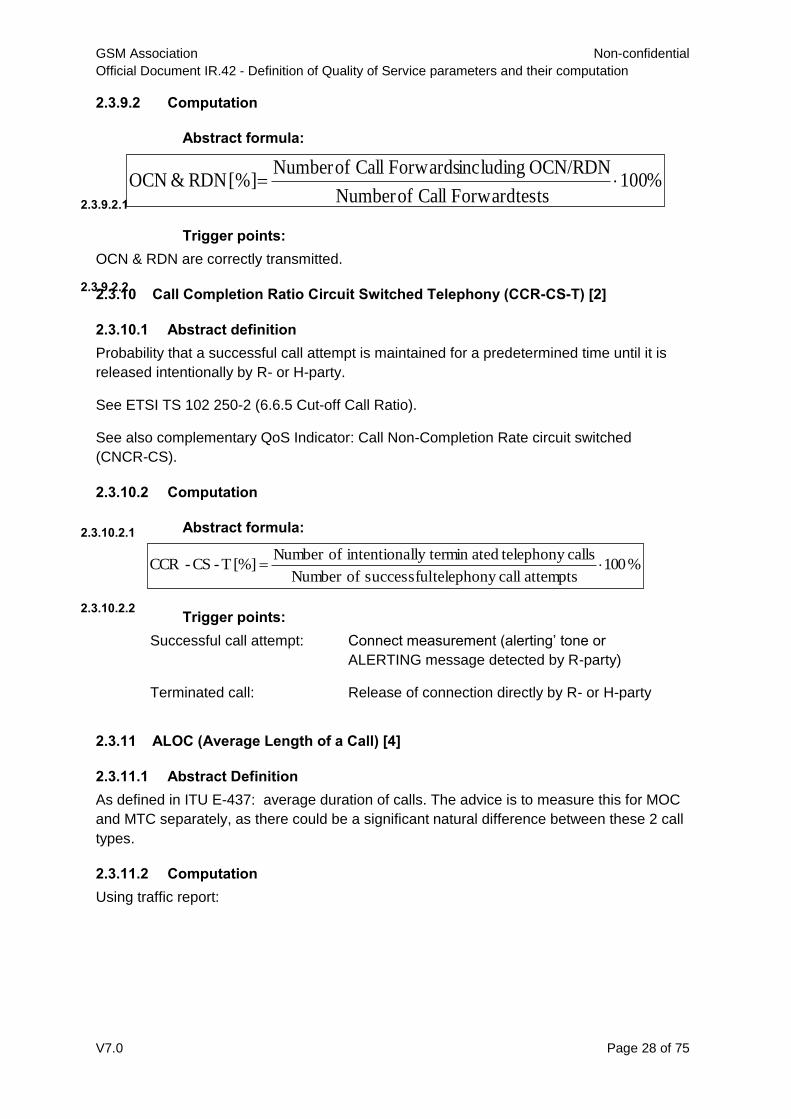
2.3.9 OCN & RDN (ISUPv2 signalling transparency) [17]Abstract definition
Effective uncorrupted transmission by the VPMN of Original Called Number, (OCN) and Redirecting Number (RDN), as defined in ITU-T Q.732.2.
Using a testing tool:
R, H and C all belong to the HPMN
R is roaming on the VPMN network while H and C are located in the HPMN
A late call forward takes places and is not optimally routed (that is, the calls is
effectively routed towards the R destination and returned to the HPMN).
100%*attempts call ofNumber
entsestablishm call successful ofNumber =[%] CSSR
%100Value Cause populated with messages ISUP RELsent ofNumber
messages ISUP RELin Value Cause duncorrupte ofNumber [%] CVREL
GSM Association Non-confidential
Official Document IR.42 - Definition of Quality of Service parameters and their computation
V7.0 Page 28 of 75
2.3.9.2 Computation
Abstract formula:
2.3.9.2.1
Trigger points:
2.3.9.2.2
OCN & RDN are correctly transmitted.
2.3.10 Call Completion Ratio Circuit Switched Telephony (CCR-CS-T) [2]
2.3.10.1 Abstract definition
Probability that a successful call attempt is maintained for a predetermined time until it is
released intentionally by R- or H-party.
See ETSI TS 102 250-2 (6.6.5 Cut-off Call Ratio).
See also complementary QoS Indicator: Call Non-Completion Rate circuit switched
(CNCR-CS).
2.3.10.2 Computation
Abstract formula: 2.3.10.2.1
Trigger points: 2.3.10.2.2
Successful call attempt: Connect measurement (alerting’ tone or
ALERTING message detected by R-party)
Terminated call: Release of connection directly by R- or H-party
2.3.11 ALOC (Average Length of a Call) [4]
2.3.11.1 Abstract Definition
As defined in ITU E-437: average duration of calls. The advice is to measure this for MOC
and MTC separately, as there could be a significant natural difference between these 2 call
types.
2.3.11.2 Computation
Using traffic report:
%100 testsForward Call ofNumber
OCN/RDN including Forwards Call ofNumber [%] RDN&OCN
%100attempts call telephonysuccessful ofNumber
calls telephonyatedlly terminintentiona ofNumber [%] T-CS-CCR

GSM Association Non-confidential
Official Document IR.42 - Definition of Quality of Service parameters and their computation
V7.0 Page 29 of 75
2.3.12 CLI Transparency [5]
Call Line Identification (CLI) between countries is often not transmitted, the display indicating
“PRIVATE”, "UNAVAILABLE" or "INTERNATIONAL". This is usually the case with different
network types and international roaming scenarios.
Overseas number may be compressed into a "domestic" format and thus possibly not be
recognizable: e.g. a US number <1 555 555 7878> may be displayed in the UK as <555 555
7878>, instead of <001 555 555 7878> (or as +1 555 555 7878), where the "+" represents
the access code to dial international numbers).
2.3.12.1 Abstract Definition
CLI needs to be delivered correctly and complete, in a way it can be used to dial back the
original called party.
2.3.12.2 Computation
2.3.13 Speech Quality on Call Basis (SpQ) [2] [21] [27] [28] [29]Abstract definition
Telephony speech quality on call basis is an indicator representing the quantification of the
end-to-end speech transmission quality of the Mobile Telephony Service. This parameter
computes the speech quality on the basis of completed calls7.
2.3.13.2 Computation
The validation of the end-to-end quality is made using MOS-LQO scales. These scales
describe the opinion of users with speech transmission and its troubles (noise, robot voice,
echo, dropouts and so on), according to ITU-T Recommendation P.862 PESQ in conjunction
with ITU-T Recommendation P.862.1, or according to ITU-T Recommendation P.863
POLQA. The algorithm used should be reported. The speech quality measurement is taken
per call. An aggregation should be made on one value for speech quality per call.
Abstract formula:
2.3.13.2.1
CS, CSFB
7 The acoustic behaviour of mobile terminals is not part of this speech quality measurement.
month ain calls MOC ofnumber Total
month ain seconds MOC of usagenetwork Total =[seconds] MOC ALOC
month ain calls MTC ofnumber Total
month ain seconds MTC of usagenetwork Total =[seconds] MTC ALOC
100%*calls ofNumber
sCLI'correct and complete ofNumber =[%]ncy transpareCLI

GSM Association Non-confidential
Official Document IR.42 - Definition of Quality of Service parameters and their computation
V7.0 Page 30 of 75
LQO-MOSf =party)-H (received Basis Callon Quality Speech Telephony
LQO-MOSf =party)-R (received Basis Callon Quality Speech Telephony
Optionally it might be useful to aggregate both speech quality values into one. In this case
the worst of both shall be used. This aggregated speech quality value shall be called SpQ
(min).
Trigger points:
2.3.13.2.2
Beginning of connection: Interchange speech samples between R-party
and H-party
End of connection: Release of connection
Note: The acoustic behaviour of terminals is not part of this speech quality
measurement.
2.3.14 CSFB Return to LTE Success Ratio
2.3.14.1 Abstract definition
This parameter measures the probability that a UE has to re-join the LTE network after a
CSFB call within a pre-determined time interval.
For a valid calculation the following preconditions must be met:
LTE coverage is present at the end of the CSFB call
A call is successfully established (with or without CSFB at H-Party)
The call is regularly disconnected (i.e. no drop)
2.3.14.2 Computation
Abstract formula
2.3.14.2.1
100 attempts LTE Return to all
attempts LTE Return to successful[%] Ratio Success LTE Return to
Trigger points
2.3.14.2.2
Start: Hang up the call
Stop: network type indicator on the UE’s display switches to LTE8Remarks
This KPI shall be separately tested for CSFB voice MO call and MT call.
8 In a measurement system with automatic call dialling this KPI is influenced by the call interval. In
particular the call interval will implicitly set the timeout for Return to LTE calculation.

GSM Association Non-confidential
Official Document IR.42 - Definition of Quality of Service parameters and their computation
V7.0 Page 31 of 75
2.3.15 CSFB Return to LTE TimeAbstract definition
This parameter measures the time needed by the UE to re-join the LTE network after a
CSFB call.
2.3.15.2 Computation
Abstract formula
2.3.15.2.1
[s] [s] Time LTE Return to eddisconnect call received LTEin message SIBfirst tt
Trigger points
2.3.15.2.2eddisconnect callt time when the call is disconnected
received LTEin message SIBfirst t time when the first SIB message in LTE is received
2.3.15.3 Remarks
This KPI shall be separately tested for CSFB voice MO call and MT call.
2.4 Short Message Service
The SMS KPIs are applied to SMS over GSM, UMTS CS or SMSoSGs.
2.4.1 Service Accessibility SMS MO (SA SMS MO) [2]
2.4.1.1 Abstract definition
Probability that the end-user can access the Short Message Service (SMS) when requested
while it is offered by display of the network indicator on the Mobile Equipment. In this case
the user wants to send a Short Message.
See ETSI TS 102 250-2 (7.4.2 SMS Service non-accessibility).
2.4.1.2 Computation
Note: For the trigger point explained here, the connection over the air interface must be
measured (for example Layer-3) and the answers of the SMSC must be counted statistically.
The protocol for every connection shows the deviation from the successful service access.
Only the first try should be measured. If the Short Message is established with the second
try this should not be counted.
Abstract formula:
2.4.1.2.1
Trigger points [for example Layer-3 messages]:
2.4.1.2.2
Start SMS service attempt: Initiate sending an SMS at Roaming side
Successful SMS service
attempt:
Receiving acknowledgement of the SMSC
attempts service SMS all ofNumber
attempts service SMS successful ofNumber [%] MO SMSity Accessibil Service

GSM Association Non-confidential
Official Document IR.42 - Definition of Quality of Service parameters and their computation
V7.0 Page 32 of 75
2.4.2 Service Accessibility SMS MT (SA SMS MT) [2]Abstract definition
Probability that the end-user can receive a Short Message from its Home Network SMS-C
while it is offered by display of the network indicator on the Mobile Equipment. In this case
the user wants to receive a Short Message.
See ETSI TS 102 250-2 (7.4.2 SMS Service non-accessibility).
2.4.2.2 Computation
Only the valid attempts have to be measured. Errors due to user mistake (for example
memory full) should be excluded.
Abstract formula:
2.4.2.2.1
Trigger points [for example Layer-3 messages]:
2.4.2.2.2 Start SMS service attempt: Initiate sending a SMS from Home SMS-C
Successful SMS service
attempt:
Receiving Short Message at Roaming side
2.4.3 Access Delay SMS MO (AD SMS-MO) [2]Abstract definition
Time between sending a Short Message to a Short Message Centre and receiving the
notification from the Short Message Centre.
See ETSI TS 102 250-2 (7.4.3 SMS Access Delay).
2.4.3.2 Computation
Abstract formula:
2.4.3.2.1
treceive: point of time the mobile equipment receives the send confirmation from the SMS
Centre
tsend SMS: point of time the user sends his SMS to the SMS Centre
Trigger points [for example Layer-3 messages]:
2.4.3.2.2
Start SMS service attempt: Initiate sending an SMS at Roaming side
Successful SMS service
attempt:
Receiving acknowledgement of the SMSC
2.4.4 Access Delay SMS MT (AD SMS-MT) [2]Abstract definition
Time between sending a Short Message from the Home Short Message Centre and
receiving the notification at the Short Message Centre.
attempts service MT-SMS all ofNumber
attempts service MT-SMS successful ofNumber [%] MT SMSity Accessibil Service
SMS sendreceive t t [s] MO SMSDelay Access

GSM Association Non-confidential
Official Document IR.42 - Definition of Quality of Service parameters and their computation
V7.0 Page 33 of 75
See ETSI TS 102 250-2 (7.4.3 SMS Access Delay).
2.4.4.2 Computation
Abstract formula:
2.4.4.2.1 [s] t- t=[s] MT SMSDelay Access SMS sendreceive
treceive: point of time the SMS Centre receives confirmation that the Short Message was
correctly delivered.
tsend SMS: point of time the Short Message leaves the SMS Centre
Trigger points [for example Layer-3 messages]:
2.4.4.2.2 Start SMS service attempt: Initiate sending a SMS from Home SMS-C
Successful SMS service
attempt:
Receiving Short Message Confirmation of
Delivery at roaming side
2.4.5 End-to-End Delivery Time for SMS MO (E2E DT SMS-MO) [2]Abstract
definition
The SMS end-to-end delivery time is the time between sending a short message from R-
party in VPMN to a Short Message Centre and H-party in HPMN receiving the very same
short message from the Short Message Centre.
See ETSI TS 102 250-2 (7.4.5 End-to-End Delivery Time).
2.4.5.2 Computation
Abstract formula:
2.4.5.2.1
[s] t- t=[s] TimeDelivery End-to-End MO SMS sendR,receiveH,
receiveH,t : point of time the H-party in the HPMN receives the short message from the SMS
Centre.
sendR,t : point of time the user sends the SMS to the SMS Centre.
Remarks:
2.4.5.2.2
Not relevant for QoS Roaming SLA since time measured is dependent on the performance
of the HPMN SMS-C.

GSM Association Non-confidential
Official Document IR.42 - Definition of Quality of Service parameters and their computation
V7.0 Page 34 of 75
2.4.6 End-to-End Delivery Time for SMS MT (E2E DT SMS-MT) [2]Abstract definition
The SMS end-to-end delivery time is the time between H-party in HPMN sending a short message to a Short Message Centre and R-party in VPMN receiving the very same short message from the Short Message Centre.
See ETSI TS 102 250-2 (7.4.5 End-to-End Delivery Time).
2.4.6.2 Computation
Abstract formula:
2.4.6.2.1 [s] t- t=[s] TimeDelivery End-to-End MT SMS sendH,receiveR,
receiveR,t : point of time the R-party in the VPMN receives the new short message from the
SMS Centre.
sendH,t : point of time the H-party sends a short message to the SMS Centre in the HPMN.
Remarks: 2.4.6.2.2
Not relevant for QoS Roaming SLA since time measured is dependent on the performance
of the HPMN SMS-C.
2.4.7 Completion Ratio SMS (CR SMS) [2] [15]Abstract definition
Ratio of received and send Test SMS from one mobile to another mobile part, excluding
duplicate received and corrupted Test SMS.
A corrupted Test SMS is a SMS with at least one bit error.
For test and measurement purposes a message is considered valid if it is delivered
successfully within a time window defined.
See ETSI TS 102 250-2 (7.4.4 SMS Completion Failure Ratio)
2.4.7.2 Computation
Abstract formula:
2.4.7.2.1
Trigger points:
2.4.7.2.2
Successfully send and received SMS via SMSC.
Time window of measurements according to user profile.
SMSTest send all ofNumber
SMSTest corrupted - SMSTest received duplicate - SMSTest received successful[%] CS SMS CR

GSM Association Non-confidential
Official Document IR.42 - Definition of Quality of Service parameters and their computation
V7.0 Page 35 of 75
2.5 Circuit Switched Data Service
2.5.1 Service Accessibility, Circuit Switched Data (SA –CSD) [15]
2.5.1.1 Abstract definition
Probability that the end-user’s DTE can access the Mobile Data Service when requested.
This will be indicated by the DTE receiving the valid ‘connect’ message from the distant
DTE.
Probability that the end-user’s DTE can access the Mobile Data Service when requested.
There are 2 layers of accessibility for CSD
Access to the target network DCE.
Access to the required data service provided by a data server.
To a user, these 2 events would be seamless and therefore the calculation for the service
access should be a composite of these 2 activities. The field test system therefore must
automate and combine the two layers to provide a single SA-CSD metric.
To combine the 2 layers should involve calculation of the success of the following actions.
ATDT command including target number.
Receive Connect from target network DCE
Send relevant command to target Data Server.
Receive valid response from Data Server
The specific commands and responses from data servers will be detailed in ‘Typical
procedures for quality of service measurement equipment’.
2.5.1.2 Computation
A successful call attempt is when the A-party DTE receives valid response from test server.
This can either be a dedicated data test server or a data server accessed when testing
functionality via the public internet.
Abstract formula:
2.5.1.2.1
Trigger points:
2.5.1.2.2
Beginning of the call
attempt:
ATDT command with dialled number sent by A-
party DTE.
Successful call attempt: Valid response received from Data Server.
2.5.2 Set-up Time (ST – CSD)Abstract definition
Time between sending of complete address information in ATDT command by A-Party and
receipt of valid response from data server.
attempts call ofNumber
attempts call successful ofNumber = CSDity Accessibil Service

GSM Association Non-confidential
Official Document IR.42 - Definition of Quality of Service parameters and their computation
V7.0 Page 36 of 75
2.5.2.2 Computation
Abstract formula:
2.5.2.2.1
t1: point of time where A-party DTE sends ATDT command
t2: point of time where connect is established (valid response received by A-party from data
server)
Trigger points:
2.5.2.2.2
Beginning of the Set-up
time measurement:
Sending of ATDT command by A-party
Successful connection: Valid response received from Data Server.
2.5.3 Data Quality (DQ-CSD)
For definitions of Data Quality Parameters refer to section 2.7.
2.5.3.1 Completion Ratio Circuit Switched Data (CR-CSD)
2.5.3.1 Abstract definition
Probability that a successful call attempt is not released except when intended by any of the
parties involved in the call.
2.5.3.2 Computation
Abstract formula: 2.5.3.2.1
Trigger points:
2.5.3.2.2
Successful call attempt: Valid response received by A-party DTE.
Completed call: DTE ‘ready’ only when call ended by either party
intentionally.
2.6 Packet Switched Data Service (General Packet Radio Service)
For test purposes it will be necessary to have the mobile test equipment in a stable state
before testing. For each test the mobile should begin by being powered on and attached but
not PDP context activated. Specific details are to be found in ‘Typical procedures for quality
of service measurements’.
Note: The bearer technology will affect the monitoring results for many of the Packet
Switched Data measurements.
12 t- t[s] Data SwitchedCircuit Time up-Set
attempts call data successful ofNumber
users endby d terminatecalls ofNumber CSD Ratio completion Call

GSM Association Non-confidential
Official Document IR.42 - Definition of Quality of Service parameters and their computation
V7.0 Page 37 of 75
2.6.1 Service Accessibility Ratio – Packet Switched Data (SA – PSD) [2] [7]
2.6.1.1 Abstract definition
Probability that a subscriber can successfully attach to the PS network. As defined in ETSI
TS 129 002. See also ETSI TS 102 250-2 (5.3 Attach Failure ratio).
There are 2 layers of accessibility for GPRS:
Access to the mobile network GPRS core infrastructure.
Access to the required data service provided by a data server.
To a user, these 2 events would be seamless and therefore the calculation for the service
access should be a composite of these 2 activities. The field test system therefore must
automate and combine the two layers to provide a single SA-PSD metric.
To combine the 2 layers should involve calculation of the success of the following actions.
Sending of valid command (for example ATD*99# (with IP address of target server))
from A party DTE to obtain IP connection.
Receive valid response from GGSN
Send valid command to target Data server.
Receive valid response from target Data server.
The specific commands and responses from data servers will be detailed in ‘Typical
procedures for quality of service measurements’.
If multiple Access Point Names (APNs) are used, the measures should be performed on a
per-APN basis for consistency in measurements.
2.6.1.2 Computation
A session will be considered set-up successfully if a valid response is received from the
target data server
Abstract formula:
2.6.1.2.1
Trigger points:
2.6.1.2.2
Beginning of the session
attempt:
Send valid command request (for example
ATD*99#
(with IP address of target server))
Successful session attempt: Valid response received from target data server
2.6.2 Set-up Time – Packet Switched Data (ST – PSD) [2]Abstract definition
Time between sending of valid command (for example ATD*99# (with IP address of target
server) message and receipt of valid response message from target data server.
attemptssession ofNumber
attemptssession successful ofNumber = PSDity Accessibil Service

GSM Association Non-confidential
Official Document IR.42 - Definition of Quality of Service parameters and their computation
V7.0 Page 38 of 75
2.6.2.2 Computation
A session will be considered set-up successfully if a valid response is received from the
target data server
Abstract formula:
2.6.2.2.1
t1: point of time where A-party valid session request command
t2: point of time where connect is established (valid response received by A-party from data
server)
Trigger points:
2.6.2.2.2Beginning of the session
attempt:
Send valid command request (for example
ATD*99#
(with IP address of target server))
Successful session attempt: Valid response received from target data server
Note for all data quality testing it is assumed that for each test, PDP Context is activated
and at the end of the individual test PDP Context is de-activated.
For definitions of Data Quality Parameters refer to section 2.7.
2.6.3 Service Integrity - Throughput (Kbit/sec) [2]
2.6.3.1 Abstract definition
This parameter describes the average data transfer rate at the network transport level (and
not at the User Application level), based on the Mean Data Rate as defined by ETSI TS 102
250-2 (6.1.7 Mean Data Rate).
The prerequisite for this parameter is network and service access.
2.6.3.2 Computation
Abstract formula:
2.6.3.2.1
Remarks:
2.6.3.2.2
The measurement of Throughput will be influenced by Packet Loss and Roundtrip Time
(Delay). Throughput measurements may also be influenced by service-side factors such as
radio cell reservation and network usage. Mobile Station ()
12 t- t[s] Data SwitchedPacket Time up-Set
meTransferTi
redtaTransferVolumeOfDaoughputBitPipeThr

GSM Association Non-confidential
Official Document IR.42 - Definition of Quality of Service parameters and their computation
V7.0 Page 39 of 75
2.6.4 Service Integrity - Goodput (Kbit/sec) [10]Abstract definition
This parameter describes the average data transfer rate at the User Application level (and not at the network transport level).
The prerequisite for this parameter is network and service access.
Goodput is defined in IETF RFC2647.
2.6.4.2 Computation
Abstract formula:
2.6.4.2.1
Goodput may be calculated as:
Please note that the definition of “useful data” depends on the user applications used for the
measurement.
Remarks:
2.6.4.2.2The measurement of Goodput will be influenced by Packet Loss and Roundtrip Time
(Delay). Goodput measurements may also be influenced by service-side factors such as
packet size and the User Application.
2.6.5 Service Integrity - Roundtrip Time [11]Abstract definition
Roundtrip Time (Roundtrip Delay) is the total time that it takes to transmit an IP packet from
the source to the destination and receive the reply packet from the destination at the source.
The prerequisite for this parameter is network and service access.
See ‘Delay’ in section 8 of PRD IR.34 ‘Inter-Service Provider IP Backbone Guidelines’.
2.6.5.2 Computation
Abstract formula:
2.6.5.2.1
Round Trip Time (ms)=(timestamp Packet received)- (timestamp Packet sent)
meTransferTi
ansferredefulDataTrVolumeOfUsdputBitPipeGoo

GSM Association Non-confidential
Official Document IR.42 - Definition of Quality of Service parameters and their computation
V7.0 Page 40 of 75
2.6.6 Service Integrity – Packet Loss [6] [11]
2.6.6.1 Abstract definition
Packet Loss is the ratio of dropped packets to all packets sent from the source to Destination
over a given period of time.
The prerequisite for this parameter is network and service access.
See ‘Packet Loss Ratio’ in section 8 of PRD IR.34 ‘Inter-Service Provider IP Backbone
Guidelines’.
See also ‘Packet Loss’ in ITU-T Y.1540.
2.6.6.2 Computation
Abstract formula:
2.6.6.2.1
The IP address should be one of the HPMN network (GGSN, WAP GW, tests server,
…)
The firewalls are not allowed to block these ICMP echo requests for the tested IP
address and Port
2.6.7 Completed Session Ratio (CoSeR – PSD)Abstract definition
Probability that a successful session attempt is not released for a reason other than
intentional by any of the parties involved in the session.
2.6.7.2 Computation
Abstract formula:
2.6.7.2.1
Trigger points:
2.6.7.2.2
Successful session attempt: Valid response received from target data server.
Completed session: Session released intentionally by either end-user.
2.6.8 Service Retainability – Average PDP Context Average Session Time
[8]Abstract definition
The average PDP context session time is the average duration of the PDP context sessions
successfully completed.
PDP Context is defined in 3GPP 29.060.
ceivedPacket
PacketSentlossPacket
Re1%100_
attemptssession data successful ofNumber
user endby other than releasednot sessions ofNumber PSD RatioSession Completed

GSM Association Non-confidential
Official Document IR.42 - Definition of Quality of Service parameters and their computation
V7.0 Page 41 of 75
2.6.8.2 Computation
Abstract formula:
2.6.8.2.1
Trigger points:
2.6.8.2.2
Start: Notification of successful PDP context activation
(Activate PDP Context Accept)
End: PDP context deactivation request initiated by the
user (Deactivate PDP Context Request)
Remarks:
2.6.8.2.3The PS bearer has to be active in the cell used by a subscriber (cf. Unavailability) and the
mobile station has to be attached as well as the respective PDP context has to be activated.
2.7 Data Service Class Definitions and Measurements
The following definitions for data services and data quality DQ are relevant for both circuit
switched and packet switched data as, the different classes of data service will be applied
identically irrespective of the data bearer system.
Note that data quality will be a result of an overall call or session. For test purposes it may
be desirable to break this down into geographically distinct measurements but for QoS
reporting should be kept to call or session lengths.
Data classes are defined in 3rd Generation Partnership Project Technical Specification
Group Services and System Aspects; QoS Concept and Architecture (3G TR 23.907) - see
Table 1.
Traffic class Conversational
class
conversational RT
Streaming class
streaming RT
Interactive class
Interactive best
effort
Background
Background
best effort
Fundamental
characteristics
Preserve time relation (variation) between information entities of the stream
Conversational pattern (stringent and low delay )
Preserve time relation (variation) between information entities of the stream
Request response pattern
Preserve payload content
Destination is not expecting the data within a certain time
Preserve payload content
Example of the
application
Voice Streaming video Web browsing Background download of emails
Table 2: UMTS QoS classes
)( ActivationPDPContextonDeactivatiPDPContext ttAveragesionTimeAverageSesPDPContext

GSM Association Non-confidential
Official Document IR.42 - Definition of Quality of Service parameters and their computation
V7.0 Page 42 of 75
2.7.1 Conversational Class Data
2.7.1.1 Abstract definition
Indicator representing the end-to-end data transmission quality of the Conversational Class
Data Service. This represents full duplex transfer of data in near real time.
2.7.1.2 Computation
The end-to-end data quality is validated by measuring the average data throughput in both
up-link and down link direction on a best effort basis. The data throughput measurement will
be computed and averaged over the duration of the session/call and reported in bits per
second. Additionally the minimum throughput averaged over 10% of the overall call/session
length, the maximum throughput over 10% of the overall call/session length and worst. The
worst delay time for the call/session should also be reported
Abstract formula:
2.7.1.2.1
Trigger points: 2.7.1.2.2
Beginning of call/session
data sample:
Interchange data frames of predefined data
between A and B-party DTE
End of call/session data
sample:
Calculation of average data throughput for
Call/session data sample
2.7.2 Streaming ClassAbstract definition
Indicator representing the end-to-end data transmission quality of the Mobile, Circuit
Switched, Streaming Class Data Service. This measure represents a delivery of data in one
direction (up-link or down-link) in near real time for example video broadcast.
Additionally the minimum throughput averaged over 10% of the call/session duration, the
maximum throughput averaged over 10% of the call/session duration and the worst block
error rate. The worst delay time for the call/session should also be reported
Note for streaming class service only the down link direction is considered, but if service
applications are introduced for uplink streaming then this can be added for calculation for
data received by B-Party
2.7.2.2 Computation
The end-to-end data quality is validated by measuring the data throughput in down link
direction on a best effort basis. The data throughput measurement will be computed and
averaged over the duration of the call/session and be reported in bits/sec.
bits/sec X side)-B dDQ(receive
bits/sec X side)-A dDQ(receive

GSM Association Non-confidential
Official Document IR.42 - Definition of Quality of Service parameters and their computation
V7.0 Page 43 of 75
Abstract formula:
2.7.2.2.1
Trigger points:
2.7.2.2.2
Beginning of Call/session
data sample:
Transmission of data frames of indexed
predefined data B-party to A-party
End of Call/session data
sample:
Calculation of average data throughput for
call/session data sample
2.7.3 Interactive ClassAbstract definition
Indicator representing the end-to-end data transmission quality of the Mobile Circuit
Switched Interactive Class Data Service. This represents duplex transfer of data in non real-
time.
2.7.3.2 Computation
The validation of the end-to-end data quality is made by the time taken to download
specified files of fixed data size to the A-party DTE when, requested by the A-party sending
a request to the data server.
Assumption: The A-party DTE has already been connected to the data server as part of the
call set-up process.
Abstract formula: 2.7.3.2.1
t1: point of time where A-party DTE sends data request.
t2: point of time where A-party receives complete uncorrupted requested file/s
Trigger points:
2.7.3.2.2
Beginning of request for
download:
Data request sent by A-party DTE
Download of file/s complete: Uncorrupted file/s received by A-party DTE.
2.7.4 Background classAbstract definition
Indicator representing the end-to-end data transmission quality of the Mobile Circuit
Switched Background Class Data Service. This represents data transfer with no real-time
dependency (although for QoS testing, data transfer time is measured).
2.7.4.2 Computation
The validation of the end-to-end data quality is made by the time taken to download a file/s
of fixed data size to the A-party DTE when, requested by the A-party sending a request to
the target server.
bits/sec X side)-A dDQ(receive
12 t- t[s] timedownload DQ

GSM Association Non-confidential
Official Document IR.42 - Definition of Quality of Service parameters and their computation
V7.0 Page 44 of 75
Assumption: The A-party DTE has already been connected to the data server as part of call
set-up process.
Abstract formula:
2.7.4.2.1
t1: point of time where A-party DTE sends data transfer request
t2: point of time where A-party receives complete uncorrupted file/s
Trigger points:
2.7.4.2.2
Beginning of request for
download:
Request sent by A-party DTE
Download of file/s complete: Uncorrupted file/s received by A-party DTE
2.8 FTP QoS Parameters
Precondition: PS attached and the respective PDP context / default EPS bearer context
activated.
Assumption: a single TCP/IP connection is applied.
2.8.1 FTP {Download|Upload} IP Service Access Success Ratio [%] [2]
2.8.1.1 Abstract definition
The IP-service access ratio denotes the probability that a subscriber can establish a TCP/IP
connection to the server of a FTP service successfully.
See ETSI TS 102 250-2 (6.1.3 FTP IP-Service Failure Ratio)
2.8.1.2 Computation
Abstract Formula
2.8.1.2.1
100 server the toconnection IPan establish toattempts all
server the toconnection IPan establish toattempts successful
[%] Ratio Success Access Service-IP Upload}| {Download FTP
Trigger Points
2.8.1.2.2
Download:
Start: Initiate file download, or the first [SYN] sent on the data socket.
Stop: File download starts, or
Method A9: Reception of the first data packet containing content
9 Method A is used for payload throughput, method B is used for transaction throughput, ref. to ETSI
TS 102 250-2, 4.2 FTP, HTTP and E-mail issues.
12 t- t[s] timedownload File DQ

GSM Association Non-confidential
Official Document IR.42 - Definition of Quality of Service parameters and their computation
V7.0 Page 45 of 75
Method B: Reception of the [ACK] from the [SYN, ACK] for active mode
connections, sending of the [ACK] for the [SYN, ACK] for passive mode
connections on the data socket.
Upload:
Start: Initiate file upload, or the first [SYN] sent on the data socket.
Stop: File upload starts, or
Method A: Sending the first data packet containing content
Method B: Reception of the [ACK] from the [SYN, ACK] for active mode
connections, sending of the [ACK] for the [SYN, ACK] for passive mode
connections on the data socket.
2.8.2 FTP {Download|Upload} IP Service Access Setup Time [s] [2]Abstract
definition
The IP-service setup time denotes the time period needed to establish a TCP/IP connection
to the server of a FTP service, from sending the initial query to the server to the point of time
when the content is sent or received.
See ETSI TS 102 250-2 (6.1.4 FTP IP-Service Setup Time)
2.8.2.2 Computation
Abstract Formula 2.8.2.2.1
[s] t- t=[s] Time Setup Service-IP Upload}| {Download FTP start access Service-IPsuccessful access Service-IP
Trigger Points 2.8.2.2.2
Download:
Start: Initiate file download, or the first [SYN] sent on the data socket.
Stop: File download starts, or
Method A: Reception of the first data packet containing content
Method B: Reception of the [ACK] from the [SYN, ACK] for active mode
connections, sending of the [ACK] for the [SYN, ACK] for passive mode
connections on the data socket.
Upload:
Start: Initiate file upload, or the first [SYN] sent on the data socket.
Stop: File upload starts, or
Method A: Sending the first data packet containing content
Method B: Reception of the [ACK] from the [SYN, ACK] for active mode
connections, sending of the [ACK] for the [SYN, ACK] for passive mode
connections on the data socket.
2.8.3 FTP {Download|Upload} Session Success Ratio [%] [2]Abstract definition
The session success ratio is the proportion of completed sessions and the total sessions that
were started successfully.
See ETSI TS 102 250-2 (6.1.5 FTP Session Failure Ratio)

GSM Association Non-confidential
Official Document IR.42 - Definition of Quality of Service parameters and their computation
V7.0 Page 46 of 75
2.8.3.2 Computation
Abstract Formula
2.8.3.2.1
100 sessions startedly successful
sessions completed[%] Ratio SuccessSession Upload}| {Download FTP
Trigger Points
2.8.3.2.2
Download:
Start: Initiate file download, or the first [SYN] sent on the control socket.
Stop: File download successfully completed, or Reception of the last data packet
containing content
Upload:
Start: Initiate file upload, or the first [SYN] sent on the control socket.
Stop: File upload successfully completed, or Reception of the [FIN, ACK] for the
last data packet containing content.
2.8.4 FTP {Download|Upload} Session Time [s] [2]Abstract definition
The session time is the time period needed to successfully complete a file transfer session.
See ETSI TS 102 250-2 (6.1.6 FTP Session Failure Ratio)
2.8.4.2 Computation
Abstract Formula 2.8.4.2.1
[s] t- t=[s] TimeSession Upload}| {Download FTP startsession endsession
Trigger Points 2.8.4.2.2
Download:
Start: Initiate file download, or the first [SYN] sent on the control socket.
Stop: File download successfully completed, or Reception of the last data packet
containing content
Upload:
Start: Initiate file upload, or the first [SYN] sent on the control socket.
Stop: File upload successfully completed, or Reception of the [FIN, ACK] for the
last data packet containing content.
2.8.5 FTP {Download|Upload} Mean Data Rate [kbit/s] [2]Abstract Formula
After a data link has been successfully established, this parameter describes the average
data transfer rate measured over the entire connect time to the service. The data transfer
shall be successfully terminated. The prerequisite for this parameter is network and service
access.
See ETSI TS 102 250-2 (6.1.7 FTP Mean Data Rate)

GSM Association Non-confidential
Official Document IR.42 - Definition of Quality of Service parameters and their computation
V7.0 Page 47 of 75
2.8.5.2 Computation
Abstract Formula
2.8.5.2.1 [s] t- t
[kbit] ed transferrdatauser [kbit/s] Rate DataMean Upload}| {Download FTP
start transfer datacomplete transfer data
Trigger Points
2.8.5.2.2
The average throughput is measured from opening the data connection to the end
of the successful transfer of the content (file).
Download:
Start: File download starts, or
Method A: Reception of the first data packet containing content
Method B: Reception of the [ACK] from the [SYN, ACK] for active mode
connections, sending of the [ACK] for the [SYN, ACK] for passive mode
connections on the data socket
Stop: File download successfully completed, or Reception of the last data packet
containing content.
Upload:
Start: Fie upload starts, or
Method A: Sending of the first data packet containing content
Method B: Reception of the [ACK] from the [SYN, ACK] for active mode
connections, sending of the [ACK] for the [SYN, ACK] for passive mode
connections on the data socket.
Stop: File upload successfully completed, or Reception of the [FIN, ACK] for the
last data packet containing content.
2.8.6 FTP {Download|Upload} Data Transfer Success Ratio [%] [2]Abstract
definition
The data transfer success ratio is the proportion of completed data transfers and data
transfers that were started successfully.
See ETSI TS 102 250-2 (6.1.8 FTP Data Transfer Cut-off Ratio)
2.8.6.2 Computation
Abstract Formula
2.8.6.2.1
100 transfersdata startedly successful
transfersdata completed
[%] Ratio SuccessTransfer Data Upload}| {Download FTP
Trigger Points
2.8.6.2.2
Download:
Start: File download starts, or
Method A: Reception of the first data packet containing content

GSM Association Non-confidential
Official Document IR.42 - Definition of Quality of Service parameters and their computation
V7.0 Page 48 of 75
Method B: Reception of the [ACK] from the [SYN, ACK] for active mode
connections, sending of the [ACK] for the [SYN, ACK] for passive mode
connections on the data socket.
Stop: File download successfully completed, or Reception of the last data packet
containing content
Upload:
Start: File upload starts, or
Method A: Sending of the first data packet containing content
Method B: Reception of the [ACK] from the [SYN, ACK] for active mode
connections, sending of the [ACK] for the [SYN, ACK] for passive mode
connections on the data socket.
Stop: File upload successfully completed, or Reception of the [FIN, ACK] for the
last data packet containing content.
2.8.7 FTP {Download|Upload} Data CapacityAbstract definition
FTP {Download|Upload} denotes the maximum FTP download or upload Bandwidth of data
capacity.
2.8.7.2 Computation
Abstract Formula 2.8.7.2.1
n
nectionEachTCPconDataRateOf1
[mbit/s]Bandwidth Upload}|{Download FTP
Trigger points 2.8.7.2.2
Start: multiple TCP/IP connections are established and download (or upload) one or multiple
FTP files from (or to) one or multiple different FTP servers in parallel.
Stop: if all FTP files are downloaded (or uploaded) or a fixed time duration is reached.
Remarks
2.8.7.2.3
The test purpose is to measure the available download or upload Bandwidth of the network
in case of PS data roaming. The FTP data contents and the establish time of the multiple
TCP/IP connections are irrelevant.
2.9 WEB Browsing (HTTP / HTTPS) QoS Parameters
Preconditions: PS attached and the respective PDP context / default EPS bearer context
activated.
The KPIs defined in this section are generic and are applicable to HTTP or HTTPS.
Assumption: a single TCP/IP connection.
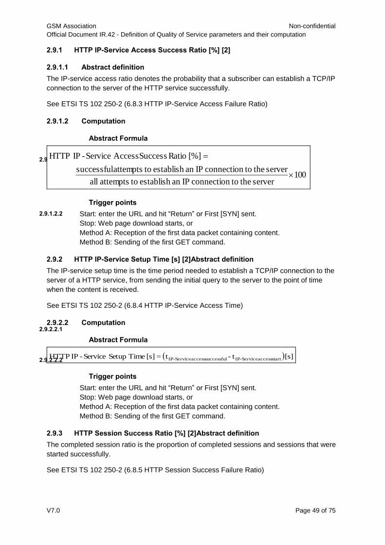
GSM Association Non-confidential
Official Document IR.42 - Definition of Quality of Service parameters and their computation
V7.0 Page 49 of 75
2.9.1 HTTP IP-Service Access Success Ratio [%] [2]
2.9.1.1 Abstract definition
The IP-service access ratio denotes the probability that a subscriber can establish a TCP/IP
connection to the server of the HTTP service successfully.
See ETSI TS 102 250-2 (6.8.3 HTTP IP-Service Access Failure Ratio)
2.9.1.2 Computation
Abstract Formula
2.9.1.2.1
100server the toconnection IPan establish toattempts all
server the toconnection IPan establish toattempts successful
[%] Ratio Success Access Service-IP HTTP
Trigger points
2.9.1.2.2 Start: enter the URL and hit “Return” or First [SYN] sent.
Stop: Web page download starts, or
Method A: Reception of the first data packet containing content.
Method B: Sending of the first GET command.
2.9.2 HTTP IP-Service Setup Time [s] [2]Abstract definition
The IP-service setup time is the time period needed to establish a TCP/IP connection to the
server of a HTTP service, from sending the initial query to the server to the point of time
when the content is received.
See ETSI TS 102 250-2 (6.8.4 HTTP IP-Service Access Time)
2.9.2.2 Computation
Abstract Formula
2.9.2.2.1
[s] t- t=[s] Time Setup Service-IP HTTP start access Service-IPsuccessful access Service-IP
Trigger points
2.9.2.2.2
Start: enter the URL and hit “Return” or First [SYN] sent.
Stop: Web page download starts, or
Method A: Reception of the first data packet containing content.
Method B: Sending of the first GET command.
2.9.3 HTTP Session Success Ratio [%] [2]Abstract definition
The completed session ratio is the proportion of completed sessions and sessions that were
started successfully.
See ETSI TS 102 250-2 (6.8.5 HTTP Session Success Failure Ratio)

GSM Association Non-confidential
Official Document IR.42 - Definition of Quality of Service parameters and their computation
V7.0 Page 50 of 75
2.9.3.2 Computation
Abstract Formula
2.9.3.2.1
100sessions startedly successful
sessions completed[%] Ratio SuccessSession HTTP
Trigger points
2.9.3.2.2
Start: enter the URL and hit “Return” or first [SYN] sent.
Stop: The complete Web page appears in the browser window, or Reception of
the last data packet containing content.
2.9.4 HTTP Session Time [s] [2]Abstract definition
The session time is the time period needed to successfully complete a HTTP session.
See ETSI TS 102 250-2 (6.8.6 HTTP Session Time)
2.9.4.2 Computation
Abstract Formula 2.9.4.2.1
[s] t- t=[s] TimeSession HTTP startsession endsession
Trigger points 2.9.4.2.2
Start: enter the URL and hit “Return” or first [SYN] sent.
Stop: The complete Web page appears in the browser window, or Reception of
the last data packet containing content
2.9.5 HTTP Mean Data Rate [kbit/s] [2]Abstract definition
After a data link has been successfully established, this parameter describes the average
data transfer rate measured over the entire connect time to the service. The data transfer
shall be successfully terminated. The prerequisite for this parameter is network and service
access.
See ETSI TS 102 250-2 (6.8.7 HTTP Mean Data Rate)
2.9.5.2 Computation
Abstract Formula
2.9.5.2.1
[s] t- t
[kbit] ed transferrdatauser [kbit/s] Rate DataMean HTTP
start transfer datacomplete transfer data
Trigger points
2.9.5.2.2
Start: Web page download starts or First [SYN] sent, or
Method A: Reception of the first data packet containing content.
Method B: Sending of the first GET command
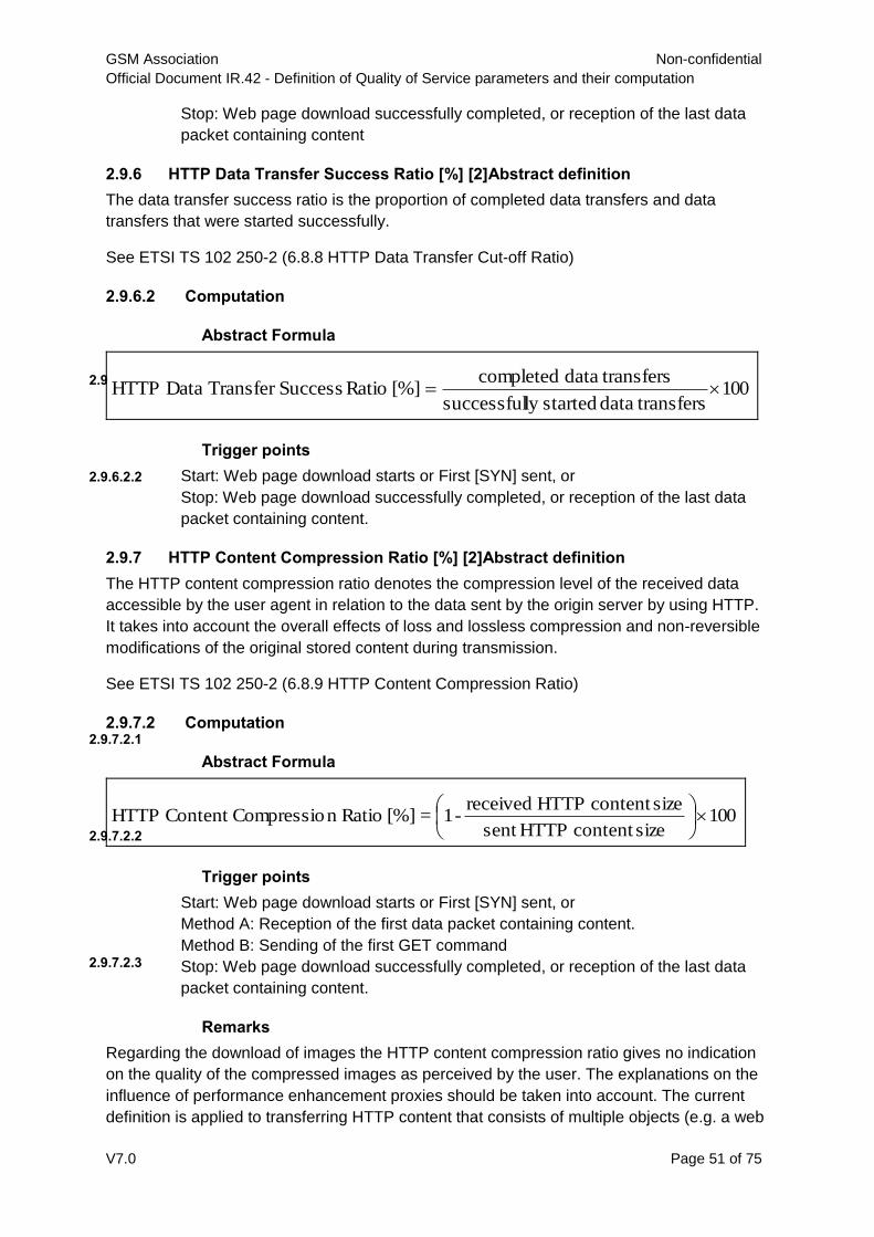
GSM Association Non-confidential
Official Document IR.42 - Definition of Quality of Service parameters and their computation
V7.0 Page 51 of 75
Stop: Web page download successfully completed, or reception of the last data
packet containing content
2.9.6 HTTP Data Transfer Success Ratio [%] [2]Abstract definition
The data transfer success ratio is the proportion of completed data transfers and data
transfers that were started successfully.
See ETSI TS 102 250-2 (6.8.8 HTTP Data Transfer Cut-off Ratio)
2.9.6.2 Computation
Abstract Formula
2.9.6.2.1100
transfersdata startedly successful
transfersdata completed[%] Ratio SuccessTransfer Data HTTP
Trigger points
2.9.6.2.2 Start: Web page download starts or First [SYN] sent, or
Stop: Web page download successfully completed, or reception of the last data
packet containing content.
2.9.7 HTTP Content Compression Ratio [%] [2]Abstract definition
The HTTP content compression ratio denotes the compression level of the received data
accessible by the user agent in relation to the data sent by the origin server by using HTTP.
It takes into account the overall effects of loss and lossless compression and non-reversible
modifications of the original stored content during transmission.
See ETSI TS 102 250-2 (6.8.9 HTTP Content Compression Ratio)
2.9.7.2 Computation
Abstract Formula
2.9.7.2.1
100sizecontent HTTPsent
sizecontent HTTP received-1=[%] Ration CompressioContent HTTP
Trigger points
2.9.7.2.2
Start: Web page download starts or First [SYN] sent, or
Method A: Reception of the first data packet containing content.
Method B: Sending of the first GET command
Stop: Web page download successfully completed, or reception of the last data
packet containing content.
Remarks
2.9.7.2.3
Regarding the download of images the HTTP content compression ratio gives no indication
on the quality of the compressed images as perceived by the user. The explanations on the
influence of performance enhancement proxies should be taken into account. The current
definition is applied to transferring HTTP content that consists of multiple objects (e.g. a web

GSM Association Non-confidential
Official Document IR.42 - Definition of Quality of Service parameters and their computation
V7.0 Page 52 of 75
page) or content that consists of a single object. The “sent HTTP content” is an external
input parameter for the calculation. It may be a constant (e.g. reference web page) or it may
be measured directly at the HTTP server during the test execution, in a different network.
2.9.8 HTTP {Download|Upload} Data CapacityAbstract definition
HTTP {Download|Upload} denotes the maximum HTTP download or upload Bandwidth of
data capacity.
2.9.8.2 Computation
Abstract Formula
2.9.8.2.1
n
nectionEachTCPconDataRateOf1
[mbit/s]Bandwidth Upload}|{Download HTTP
Trigger points
2.9.8.2.2Start: multiple TCP/IP connections are established and download (or upload) one or multiple
HTTP files from (or to) one or multiple different HTTP servers in parallel.
Stop: if all HTTP files are downloaded (or uploaded) or a fixed duration is reached.
Remarks 2.9.8.2.3
The test purpose is to measure the available download or upload Bandwidth of the network
in case of PS data roaming. The HTTP data contents and the establish time of the multiple
TCP/IP connections are irrelevant.
2.10 PING QoS Parameters
2.10.1 PING Packet Loss Ratio
2.10.1.1 Abstract definition
PING packet Loss ratio is the proportion of dropped PING packets vs. the total PING
packets sent.
See also the section: Service integrity - Packet Loss
2.10.1.2 Computation
Abstract Formula
2.10.1.2.1
100)sent packetsPING ofnumber Total
received packetsPING Succssful1([%] Ratio LossPacket PING
Trigger Points
2.10.1.2.2
Start: ICMP echo request sent,
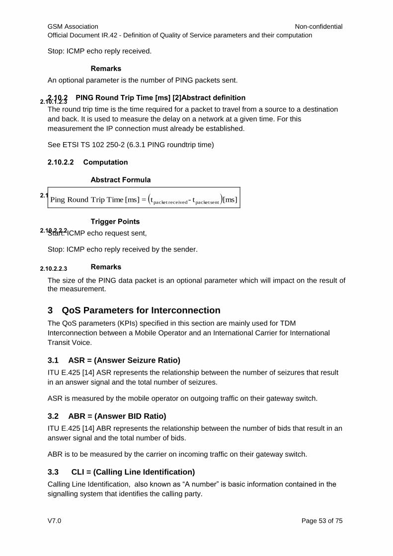
GSM Association Non-confidential
Official Document IR.42 - Definition of Quality of Service parameters and their computation
V7.0 Page 53 of 75
Stop: ICMP echo reply received.
Remarks
2.10.1.2.3
An optional parameter is the number of PING packets sent.
2.10.2 PING Round Trip Time [ms] [2]Abstract definition
The round trip time is the time required for a packet to travel from a source to a destination
and back. It is used to measure the delay on a network at a given time. For this
measurement the IP connection must already be established.
See ETSI TS 102 250-2 (6.3.1 PING roundtrip time)
2.10.2.2 Computation
Abstract Formula
2.10.2.2.1 [ms] t- t=[ms] Time Trip Round Ping sentpacket receivedpacket
Trigger Points
2.10.2.2.2Start: ICMP echo request sent,
Stop: ICMP echo reply received by the sender.
Remarks 2.10.2.2.3
The size of the PING data packet is an optional parameter which will impact on the result of the measurement.
3 QoS Parameters for Interconnection
The QoS parameters (KPIs) specified in this section are mainly used for TDM
Interconnection between a Mobile Operator and an International Carrier for International
Transit Voice.
3.1 ASR = (Answer Seizure Ratio)
ITU E.425 [14] ASR represents the relationship between the number of seizures that result
in an answer signal and the total number of seizures.
ASR is measured by the mobile operator on outgoing traffic on their gateway switch.
3.2 ABR = (Answer BID Ratio)
ITU E.425 [14] ABR represents the relationship between the number of bids that result in an
answer signal and the total number of bids.
ABR is to be measured by the carrier on incoming traffic on their gateway switch.
3.3 CLI = (Calling Line Identification)
Calling Line Identification, also known as “A number” is basic information contained in the
signalling system that identifies the calling party.

GSM Association Non-confidential
Official Document IR.42 - Definition of Quality of Service parameters and their computation
V7.0 Page 54 of 75
CLIP – CLI Presentation provides for the calling user number to be displayed to the called
user.
CLIR – CLI Restriction provides a means for the calling user to restrict presentation of its
MSISDN to the called user.
A more detailed definition is referred to in section 2.3.11.
3.4 NER = (Network Efficiency Ratio)
ITU E.425 [14] NER expresses the relationship between the number of seizures and the sum
of the seizures resulting in an answer signal OR busy signal OR no answer. It excludes the
effects of customer behaviour and terminal behaviour. It represents the ability of the network
to deliver calls to the far end terminal.
A more detailed definition is referred to in sections 2.3.1 and 2.3.2.
3.5 PGAD = (Post Gateway Delay)
ITU E.437 [4] PGAD is the time interval between the seizure of the international circuit and
the receipt of the answer supervision.
3.6 PDD = (Post Dial Delay)
ITU E.431 [13] PDD is the time interval between dialling completion and the call connection
(ringing tone).
A more detailed definition is provided in sections 2.3.3 and 2.3.4.
3.7 ALOC = (Average Length of Conversation)
ITU E.437 [4] ALOC measures the average duration of calls. A statistically significant
difference in ALOC to the same destination on different routes may be investigated.
A more detailed definition is referred to in section 2.3.10.
3.8 Speech Quality on Sample Basis.
Reference: ITU-T Recommendation P.862 [21] in conjunction with ITU-T Recommendation
P.862.1 [29].
A more detailed definition is referred to in the section 2.3.12.
4 VoLTE / ViLTE Quality Parameters
This section contains VoLTE [31] and ViLTE [32] quality KPIs for interconnect and roaming
[18] [30] [33]. The quality parameters (KPIs) are divided into seven groups:
Accessibility (IMS Registration quality)
Voice / video service integrity and retainability
SRVCC (PS-CS) quality
EPS bearer quality

GSM Association Non-confidential
Official Document IR.42 - Definition of Quality of Service parameters and their computation
V7.0 Page 55 of 75
Media transport quality
Diameter quality10
The first three groups contribute to the service quality over LTE. The last three groups
characterize the quality of networks / transport.
4.1 VoLTE / ViLTE Service Quality Parameters
VoLTE / ViLTE service QoS parameters (KPIs) contains the service accessibility, integrity
mobility and preservation.
4.1.1 VoLTE / ViLTE Accessibility Parameters
4.1.1.1 IMS Registration Success Ratio
The SIP Registration procedure in IR.92 [31] and IR.94 [32] shall be followed. See also 5.3.2
of ETSI TR 103 219 [34].
Abstract definition
4.1.1.1.1This parameter denotes the probability that UE successfully registers to IMS.
100 attempts ion RegistratIMS all
attempts ion RegistratIMS successful[%] RatioSuccess ion RegistratIMS
4.1.1.2 IMS Registration Time
The SIP Registration procedure in IR.92 [31] and IR.94 [32] shall be followed. See ETSI TR
103 219 [34] section 5.3.3.
Abstract formula 4.1.1.2.1
4.1.1.3 IMS Third-party Registration Success Ratio
Abstract definition
4.1.1.3.1
This parameter denotes the probability for the 3rd-party IMS registrations to be successfully
performed.
100 attempts trationpartyRegis-3rd IMS all
attempts strationparty Regi-3rd IMS successful[%] ratio success onregistratiparty -3rd IMS
10
The Diameter KPIs, denoting the quality of PCC and DRA quality, are not applied to e2e testing.
[s] [s] Time ion RegistratIMS ion RegistratIMS requests UE onregistrati IMS confirmsNetwork tt

GSM Association Non-confidential
Official Document IR.42 - Definition of Quality of Service parameters and their computation
V7.0 Page 56 of 75
4.1.2 VoLTE / ViLTE Service Quality Parameters
The entire quality parameters in this section characterize the QoS aspect of the VoLTE /
ViLTE service integrity.
For the simplification of the technical description in a roaming scenario, H-party denotes a
party at HPMN, R-party denotes a Roaming party at the VPMN. In an interconnect scenario,
A-party denotes a party at HPMN A and B-party denotes a party at HPMN B where PMN A
and PMN B are interconnected.
For a valid KPI test, the following preconditions need to be met [34]:
Default QCI5 EPS bearer context for the IMS well-known APN shall be established
and the EPS ATTACH message shall contain "IMS PS Voice" in the voice domain
preference list.
IMS shall be present.
LTE coverage shall be present.
IMS registration shall be successfully accomplished.
4.1.2.1 VoLTE / ViLTE service access success ratio – NER MO (%)
Abstract definition 4.1.2.1.1
The KPI denotes the probability for the end-user to access the VoLTE / ViLTE service and
initiate a voice or video call. See also 2.3.1.1.
Abstract formula 4.1.2.1.2
100 attempts call totalofNumber
attempts call successful ofNumber [%]ity Accessibil MOVoLTE
100 attempts call totalofNumber
attempts call successful ofNumber [%]ity Accessibil MOViLTE
Trigger points from an end user’s viewpoint, see 2.3.1.2..
Technical description
Start test: SIP "INVITE" sent by the R- / A-party.
Successfully stop test: ”180 Ringing” is received by the R- / A-party.
Unsuccessfully stop test: either the R- / A-party receives a 4xx error message as response
to the "INVITE", or timeout.
4.1.2.2 VoLTE / ViLTE service access success ratio – NER MT (%)
Abstract definition
4.1.2.2.1
The KPI denotes the probability that the end-user can access the VoLTE / ViLTE service and
receive a VoLTE / ViLTE call. See also 2.3.2.

GSM Association Non-confidential
Official Document IR.42 - Definition of Quality of Service parameters and their computation
V7.0 Page 57 of 75
Abstract formula
4.1.2.2.2
100 attempts call totalofNumber
attempts call successful ofNumber [%]ity Accessibil MTVoLTE
100 attempts call totalofNumber
attempts call successful ofNumber [%]ity Accessibil MTViLTE
Trigger points from an end user’s viewpoint, see also 2.3.2.1.
Test start: Beginning of a call attempt of H-party / B-party, SIP "INVITE" received by the R-
Party / A-party.
Successfully Test stop : ”180 Ringing” is sent by the R-party / A-party and ”180 Ringing” is
received by H-party / B-party.
Unsuccessfully test stop : either the H-/ B-party receives a 4xx error message as response
to the "INVITE", or timeout.
4.1.2.3 VoLTE / ViLTE session setup time – PDD-MO (s)
Abstract definition 4.1.2.3.1
Time needed to setup an MO VoLTE / ViLTE call. See also 2.3.3.1.
Note: The KPI VoLTE / ViLTE session setup in this definition is referred to a
complete VoLTE / ViLTE session establishment, therefore is not applied to
SRVCC when voice session is handed over legacy technologies during the
voice session setup.
Abstract formula 4.1.2.3.2
[s] [s] Time Setup Session MOVoLTE session call initiatesparty Callingonnotificati receivesparty Calling tt
[s] [s] Time Setup Session MOViLTE session call initiatesparty Callingonnotificati receivesparty Calling tt
Test start: R- / A- party initiates VoLTE session and sends SIP "INVITE"
Successful test stop : SIP: "200 OK (INVITE)" sent by H- / B-party and SIP: "200 OK
(INVITE)" received by R- / A-party [34]. In manual test, the time for the user accepting the
incoming call is excluded in the calculation.
Unsuccessful Test stop : R- / A-party receives a 4XX error message - the session set-up is
cancelled or does not receive any notification within a pre-determined time.
4.1.2.4 VoLTE / ViLTE session setup time – PDD-MT (s)
Abstract definition
4.1.2.4.1
Time needed to setup an MT VoLTE / ViLTE call. See also 2.3.4.1.
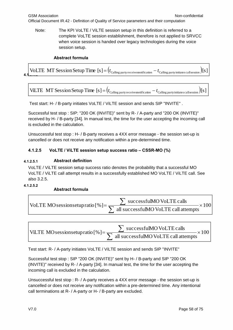
GSM Association Non-confidential
Official Document IR.42 - Definition of Quality of Service parameters and their computation
V7.0 Page 58 of 75
Note: The KPI VoLTE / ViLTE session setup in this definition is referred to a
complete VoLTE session establishment, therefore is not applied to SRVCC
when voice session is handed over legacy technologies during the voice
session setup.
Abstract formula
4.1.2.4.2 [s] [s] Time Setup Session MTVoLTE session call initiatesparty Callingonnotificati receivesparty Calling tt
[s] [s] Time Setup Session MTViLTE session call initiatesparty Callingonnotificati receivesparty Calling tt
Test start: H- / B-party initiates VoLTE / ViLTE session and sends SIP "INVITE" .
Successful test stop : SIP: "200 OK (INVITE)" sent by R- / A-party and "200 OK (INVITE)"
received by H- / B-party [34]. In manual test, the time for the user accepting the incoming call
is excluded in the calculation.
Unsuccessful test stop : H- / B-party receives a 4XX error message - the session set-up is
cancelled or does not receive any notification within a pre-determined time.
4.1.2.5 VoLTE / ViLTE session setup success ratio – CSSR-MO (%)
Abstract definition 4.1.2.5.1
VoLTE / ViLTE session setup success ratio denotes the probability that a successful MO
VoLTE / ViLTE call attempt results in a successfully established MO VoLTE / ViLTE call. See
also 3.2.5.
Abstract formula 4.1.2.5.2
100 attempts call VoLTE MOsuccessful all
calls VoLTE MOsuccessful[%] ratio setup session MOVoLTE
100 attempts call VoLTE MOsuccessful all
calls VoLTE MOsuccessful[%] ratio setup session MOViLTE
Test start: R- / A-party initiates VoLTE / ViLTE session and sends SIP "INVITE"
Successful test stop : SIP "200 OK (INVITE)" sent by H- / B-party and SIP "200 OK
(INVITE)" received by R- / A-party [34]. In manual test, the time for the user accepting the
incoming call is excluded in the calculation.
Unsuccessful test stop : R- / A-party receives a 4XX error message - the session set-up is
cancelled or does not receive any notification within a pre-determined time. Any intentional
call terminations at R- / A-party or H- / B-party are excluded.
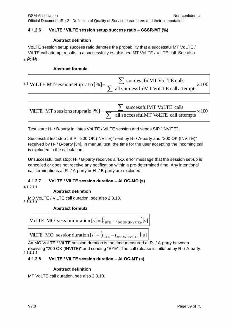
GSM Association Non-confidential
Official Document IR.42 - Definition of Quality of Service parameters and their computation
V7.0 Page 59 of 75
4.1.2.6 VoLTE / ViLTE session setup success ratio – CSSR-MT (%)
Abstract definition
4.1.2.6.1
VoLTE session setup success ratio denotes the probability that a successful MT VoLTE /
ViLTE call attempt results in a successfully established MT VoLTE / ViLTE call. See also
3.2.6.
Abstract formula
4.1.2.6.2 100 attempts call VoLTE MTsuccessful all
calls VoLTE MTsuccessful[%] ratio setup session MTVoLTE
100 attempts call VoLTE MTsuccessful all
calls VoLTE MTsuccessful[%] ratio setup session MTViLTE
Test start: H- / B-party initiates VoLTE / ViLTE session and sends SIP "INVITE" .
Successful test stop : SIP: "200 OK (INVITE)" sent by R- / A-party and "200 OK (INVITE)"
received by H- / B-party [34]. In manual test, the time for the user accepting the incoming call
is excluded in the calculation.
Unsuccessful test stop: H- / B-party receives a 4XX error message that the session set-up is
cancelled or does not receive any notification within a pre-determined time. Any intentional
call terminations at R- / A-party or H- / B-party are excluded.
4.1.2.7 VoLTE / ViLTE session duration – ALOC-MO (s)
Abstract definition 4.1.2.7.1
MO VoLTE / ViLTE call duration, see also 2.3.10.
Abstract formula
4.1.2.7.2
[s] [s] duration session MOVoLTE (INVITE)OK 200BYE tt
[s] [s] duration session MOViLTE (INVITE)OK 200BYE tt
An MO VoLTE / ViLTE session duration is the time measured at R- / A-party between
receiving "200 OK (INVITE)" and sending “BYE”. The call release is initiated by R- / A-party.
4.1.2.8 VoLTE / ViLTE session duration – ALOC-MT (s)
Abstract definition
4.1.2.8.1
MT VoLTE call duration, see also 2.3.10.

GSM Association Non-confidential
Official Document IR.42 - Definition of Quality of Service parameters and their computation
V7.0 Page 60 of 75
Abstract formula
4.1.2.8.2
[s] [s] duration session MTVoLTE (INVITE)OK 200BYE tt
[s] [s] duration session MTViLTE (INVITE)OK 200BYE tt
An MT VoLTE / ViLTE session duration is the time measured at R- / A-party between
sending "200 OK (INVITE)" and receiving “BYE”. The call release is initiated by H- / B-party.
4.1.2.9 OIP transparency – CLI transparency
Abstract definition
4.1.2.9.1
VoLTE call originating identification presentation (OIP) needs to be delivered and presented
correctly and complete. It can be used to call back to the original called party. See also
2.3.11.
Abstract formula
4.1.2.9.2
100 calls VoLTE successful ofNumber
OIPscorrect and complete ofNumber [%] rationcy transpareOIP
4.1.2.10 VoLTE speech quality (SpQ MOS-LQO)
The VoLTE Speech Quality represents the end-to-end speech quality of the VoLTE service.
ETSI TS 102 250-2 [2] and defines two variants of a "Telephony Speech Quality" KPI. Both
are based on the same single measurement. A single measurement consist of the MOS-
LQO value determined for a single transferred speech sample, according to ITU-T P.863
POLQA [27]. A speech call usually consists of multiple speech samples transferred in both
directions.
The first variant, called "Telephony Speech Quality on Call Basis" (ETSI TS 102 250-2 [2]
clause 6.6.3) does a pre-aggregation of the measured MOS-LQO values to one value per
call (in either direction). ETSI TS 102 250-2 does not specify the aggregation method for this
pre-aggregation. A suitable method can be found in ETSI TR 102 506 [28].
The second variant, called "Telephony Speech Quality on Sample Basis" (ETSI TS 102 250-
2 clause 6.6.4) does not pre-aggregate the measured MOS-LQO values. In other words, one
call will result in multiple values for this KPI.
Averaging the results obtained in a measurement campaign with repeated calls will in
general yield different statistics for the two variants. Due to its pre-aggregation, the
"Telephony Speech Quality on Call Basis" focusses more on how users judge entire calls,
while the "Telephony Speech Quality on Sample Basis" gives insight into the overall speech
transmission quality for a particular connection or interconnection.
Abstract definition
4.1.2.10.1
VoLTE speech quality in roaming is measured on Call Basis, See also 2.3.12.

GSM Association Non-confidential
Official Document IR.42 - Definition of Quality of Service parameters and their computation
V7.0 Page 61 of 75
Abstract formula
4.1.2.10.2
LQO-MOSf =party)- H(received BasisCall onQuality Speech VoLTE
LQO-MOSf =party)- R(received BasisCall onQuality Speech VoLTE
The validation of the end-to-end quality is made using MOS-LQO scales [2]. These scales
describe the opinion of users with speech transmission and its troubles (noise, robot voice,
echo, dropouts, time scaling introduced by the jitter buffer, etc.) according to ITU-T P.863
[27]. The scale used has to be reported. An aggregation for measurement campaigns in
VoLTE roaming is made on call basis (the 1st variant).
The KPI shall be tested at the call terminating side and at the call originating side. The two
streams shall be successfully tested at the same time.
4.1.2.11 VoLTE speech quality (SpQ R-Factor-LQ)
Abstract definition
4.1.2.11.1The R-Factor is an estimated speech quality rating defined by the E-Model (ITU-T G.107.1
[35]). As an alternative method of assessing call quality, R-Factor is scaling from 0 to 120. It
can also be calculated from MOS-LQO value according to ITU-T P.863 – POLQA [27].
Abstract formula 4.1.2.11.2
LQ-G.107f =party)- H(receivedFactor -Quality R Speech VoLTE
LQ-G.107f =party)- R(receivedFactor -Quality R Speech VoLTE
The KPI shall be tested at the call terminating side and at the call originating side. The two
streams shall be successfully tested at the same time. The table below shows a proposed
mapping range between the user’s satisfaction, MOS and R-Factor scales.

GSM Association Non-confidential
Official Document IR.42 - Definition of Quality of Service parameters and their computation
V7.0 Page 62 of 75
User satisfaction level MOS scale R-Factor scale
Very satisfied 4.3 - 5.0 90 - 100
Satisfied 4.0 - 4.3 80 - 90
Some users satisfied / dissatisfied 3.6 - 4.0 70 - 80
Many users dissatisfied 3.1 - 3.6 60 - 70
Nearly all users dissatisfied 2.6 - 3.1 50 - 60
Not recommended 1.0 - 2.6 < 50
Table 3: Proposed mapping MOS and R-Factor scales
4.1.2.12 ViLTE Audio Quality (SpQ MOS-LQO) on sample basis
Abstract definition
4.1.2.12.1The KPI of ViLTE audio speech quality on sample basis is an indicator representing the
quantification of the end-to-end voice transmission quality as perceived by the user. This
parameter computes the speech quality on a sample basis. See also 6.7.9 of [2].
Abstract formula 4.1.2.12.2
LQO-MOSf =party)- H(received basis sample onquality speech ViLTE
LQO-MOSf =party)- R(received basis sample onquality speech ViLTE
The KPI shall be tested at the call terminating side and at the call originating side. The two
audio streams shall be successfully tested at the same time together with a successful test
on the two video streams.
Optionally it might be useful to aggregate both speech quality values into one. In this case
the worst of both shall be used. This aggregated speech quality value shall be called SpQ
(min).
4.1.2.13 ViLTE Video quality (MOS)
ViLTE video quality KPI is characterized by the Mean Opinion Score according to PEVQ
MOS [41].
Abstract definition
4.1.2.13.1
End-to-end quality of the video signal as perceived by the end user during a ViLTE session.
This parameter computes the video quality on a sample basis. See also 6.7.10 of [2].
Abstract formula
4.1.2.13.2
MOS-PEVQf =party)- H(received basis sample onquality videoViLTE
MOS-PEVQf =party)- R(received basis sample onquality videoViLTE

GSM Association Non-confidential
Official Document IR.42 - Definition of Quality of Service parameters and their computation
V7.0 Page 63 of 75
The KPI shall be tested at the video call terminating side and at the video call originating
side. The two video streams shall be successfully tested at the same time together with a
successful test on the two audio streams.
4.1.3 SRVCC (PS-CS) Quality Parameters [34]
SRVCC is the quality of voice mobility between 4G and the legacy technologies. For a valid
KPI calculation the following preconditions need to be met:
EPS bearer should be established and the EPS ATTACH message should contain
"IMS PS Voice" as well as "CS Voice" in the voice domain preference list.
SRVCC can have different variants depending on the supporting mid-call, alerting or pre-
alerting state of a VoLTE call when the call is handed over to UMTS or GSM.
4.1.3.1 SRVCC Success Ratio [34]
Abstract Definition
4.1.3.1.1The KPI is the probability that UE successfully handover a VoLTE call to UMTS or GSM.
4.1.3.2 Abstract Formula
100 sinvocation SRVCC all
handovers SRVCC successful[%] RatioSuccess SRVCC
4.1.3.3 SRVCC Time [34]
For a valid KPI calculation the following preconditions need to be met:
EPS bearer should be established and the EPS ATTACH message should contain
"IMS PS Voice" as well as "CS Voice" in the voice domain preference list.
An SRVCC handover to UMTS or GSM is successful.
Abstract Definition
4.1.3.3.1
The KPI specifies the time taken to successfully handover a VoLTE call to UMTS or GSM.
Abstract Formula
4.1.3.3.2
[s] [s] Time SRVCC invokedhandover SRVCC completedly successfulhandover SRVCC tt
4.2 VoLTE / ViLTE Networks & Transport QoS Parameters
The VoLTE / ViLTE networks and transport KPIs contains EPS bearer quality, RTP transport
quality and DIAMETER KPIs.
4.2.1 VoLTE / ViLTE EPS Bearer Quality Parameters
This section contains the EPS bearer KPIs for SIP signalling, voice and video media in the
VoLTE / ViLTE context.

GSM Association Non-confidential
Official Document IR.42 - Definition of Quality of Service parameters and their computation
V7.0 Page 64 of 75
4.2.1.1 Default EPS Bearer Context Activation Success Ratio
Default EPS bearer context is established and connected to the IMS well-known APN. If a
VoLTE / ViLTE capable UE is involved in the KPI test, then a single or dual default EPS
bearer contexts can be established in the EPS attach procedure. Only the default bearer
context for the IMS well-known APN connection is concerned for this KPI.
Abstract formula
4.2.1.1.1
100 sinitiation connectionPDN APN) known- wellIMS (To
successesent establishm connectionPDN APN) known- wellIMS (To
[%] RatioSuccess ActivationContext Bearer PS Default E5 QCI
See section 2.2.10 for more details.
4.2.1.2 Default EPS Bearer Context Activation Time
Default EPS bearer context is established and connected to the IMS well-known APN.
If a VoLTE / ViLTE capable UE is involved in the KPI test; a single or dual default EPS
bearer contexts can be established in the EPS attach procedure. Only the default bearer
context for the IMS well-known APN connection is concerned for this KPI. See also 2.2.11.
Abstract formula 4.2.1.2.1
[s] t- t
=[s] Time ActivationContext Bearer EPS Default 5 QCI
initiation connection PDN IMSentestablishm connection PDN IMS The default QCI 5 EPS bearer context is used in AM for SIP Signalling and SMSoIP.
4.2.1.3 Default EPS Bearer Downlink GBR
The KPI indicates the Guaranteed Bit Rate by the network in Downlink; the value taken from
EPS Quality of Service information element assigned by EPC [46].
4.2.1.4 Default EPS Bearer Uplink GBR
The KPI indicates the Guaranteed Bit Rate by the network in Uplink; the value taken from
EPS Quality of Service information element assigned by EPC [46].
4.2.1.5 Default EPS Bearer QCI
The KPI indicates the Quality of Service Class Identifier (QCI) for the default EPS bearer;
the value taken from EPS Quality of Service information element assigned by EPC [46].
QCI=5 is expected.
4.2.1.6 Dedicated EPS Bearer Context Activation Success Ratio
Dedicated EPS bearer context is established to transport the IMS-based voice media. The
dedicated EPS bearer context for VoLTE is a Persistent EPS bearer context. See also
2.2.12.

GSM Association Non-confidential
Official Document IR.42 - Definition of Quality of Service parameters and their computation
V7.0 Page 65 of 75
Abstract formula
4.2.1.6.1
100 sinitiation activationbearer EPSdedicated
successes activationbearer EPSdedicated
[%] Ratiosuccess ActivationContext Bearer EPSDedicated
The dedicated QCI1 GBR bearer is used in UM for the conversational voice service of
VoLTE and ViLTE audio.
The dedicated QCI2 GBR bearer or QCI 8/9 non-GBR bearer is used in AM for the ViLTE
conversational video service.
4.2.1.7 Dedicated EPS Bearer Context Activation Time
Dedicated EPS bearer context is established to transport the IMS-based voice media. The
dedicated EPS bearer context for VoLTE is a Persistent EPS bearer context. See also
2.2.13.
Abstract formula
4.2.1.7.1
[s] t- t
=[s] Time ActivationContext Bearer EPSDedicated
initiation activationcontext Bearer EPSDedicatedsuccess activationcontext Bearer EPSDedicated
The dedicated QCI1 GBR bearer is used in UM for the conversational voice service of
VoLTE and ViLTE audio.
The dedicated QCI2 GBR bearer or QCI 8/9 non-GBR bearer is used in AM for the ViLTE
conversational video service.
4.2.1.8 Dedicated EPS Bearer Downlink GBR
The KPI indicates the Guaranteed Bit Rate by the network in Downlink; the value taken from
EPS Quality of Service information element assigned by EPC [46].
4.2.1.9 Dedicated EPS Bearer Uplink GBR
The KPI indicates the Guaranteed Bit Rate by the network in Uplink; the value taken from
EPS Quality of Service information element assigned by EPC [46].
4.2.1.10 Dedicated EPS Bearer QCI
The KPI indicates the Quality of Service Class Identifier (QCI) for the Dedicated EPS bearer;
he value taken from EPS Quality of Service information element assigned by EPC [46].
4.2.1.11 IP data volume Rx
Abstract definition
4.2.1.11.1
IP data volume Rx denotes the total volume (in Kbytes or Mbytes) of IP data received at Rx
on an EPS bearer. The IP header is included in the calculation.

GSM Association Non-confidential
Official Document IR.42 - Definition of Quality of Service parameters and their computation
V7.0 Page 66 of 75
Abstract formula
4.2.1.11.2[KB] engthIP_PacketL received edata volum IP
1
Nr
Nr is the total number of RTP packets received at Rx.
If QCI5, the KPI measures the IP data volume of SIP signalling and SMSoIP within a determined period.
If QCI1, the KPI measures the voice IP data volume within a VoLTE or ViLTE call duration.
If QCI2 or QCI 8/9, the KPI measures the video IP data volume within a ViLTE call duration.
4.2.1.12 IP data volume Tx
Abstract definition
4.2.1.12.1IP data volume Tx denotes the total volume (in KB or MB) of IP data transmitted from Tx on
an EPS bearer. The IP header is included in the calculation.
Abstract formula 4.2.1.12.2
[KB] engthIP_PacketL ed transmittedata volum IPNt
1
Nt is the total number of RTP packets transmitted from Tx.
If QCI5, the KPI measures the IP data volume of SIP signalling and SMSoIP within a determined period.
If QCI1, the KPI measures the voice IP data volume within a VoLTE or ViLTE call duration.
If QCI2 or QCI 8/9, the KPI measures the video IP data volume within a ViLTE call duration.
4.2.2 VoLTE / ViLTE Media Transport Quality Parameters
The VoLTE media uses symmetric RTP over UDP to transport voice [42]. The RTP quality is
the key factor for the media transport. Because of the symmetry of the RTP protocol [43] the
RTP KPIs in this section are relevant for the receiver Rx and transmitter Tx of the both ends
(call originator and terminator).
The ViLTE media uses two separate RTP connections to transport audio and video streams.
The audio and video RTP quality KPI are separately measured when two RTP connections
are present during the test.
The media transport quality KPIs defined in this section are end-to-end quality parameters. It
is assumed that for a typical VoLTE / ViLTE call between 2 UEs (particularly in an active test
between two probes), the RTP/RTCP is sent end-to-end between the UEs. The RTP packets
can traverse a bunch of RTP-“translators”, e.g. IMS-AGW and TrGW, if network-to-network
interface (NNI) is encountered. The translators do not change the RTP packet payload
contents apart from the Network Address and port translation (NAPT) function (i.e. only IP
header and probably also UDP header are changed).

GSM Association Non-confidential
Official Document IR.42 - Definition of Quality of Service parameters and their computation
V7.0 Page 67 of 75
4.2.2.1 RTP Max & Mean Packet Delay Variation Rx
The RTP Packet Delay Variation is measured at the e2e Tx/Rx pair on the incoming stream
at Rx [44].
Abstract definition
4.2.2.1.1
An RTP packet transit time D is the transfer time of a voice / video RTP stream from Tx to
Rx individually identifiable IP packet, observed at Tx and Rx. D = (R – T) where T is the RTP
timestamp of the packet at Tx, and R is the arrival time of the packet at Rx in the voice /
video RTP stream (of interest within a measurement time interval).
D is also called RTP packet one-way-delay, which is relying on the clock (Time-Stamp)
synchronization between Tx and Rx – a kind of two points time measurement.
The mean RTP packet one-way-delay (OWD) is the average of delay of a voice / video RTP
stream from Tx to Rx. The test accuracy of OWD relies on the clock synchronization
between Tx and Rx.
Taking the minimum transit time in the voice / video RTP stream as the reference, a packet
delay variation PDVi is the difference between the transit time and the reference in the voice
/ video RTP stream . PDVi = Di - Dmin [45], where Di = (Ri – Ti ) is the ith packet transit
time, Ti is the RTP timestamp of packet i at Tx, and Ri is the arrival time of the packet i at Rx
in the voice / video RTP stream within a measurement time interval.
Dmin is the transit time of the packet with the lowest value for delay (minimum) over the
current test interval. Values of PDV may be zero or positive, and quantiles of the PDV
distribution are direct indications of delay variation. PDV is a version of the one-way-delay
distribution, shifted to the origin by normalizing to the minimum delay.
An RTP max PDV is the difference between the maximum transit time and the minimum
transit time in the voice / video RTP stream within a measurement time interval, measured at
Rx.
An RTP mean PDV is the difference between the average transit time and the minimum
transit time in the voice / video RTP stream within a measurement time interval, measured at
Rx.
Abstract formula
4.2.2.1.2
[ms] ) ([ms] max PDV RTP minmax DD
[ms] ) nr
([ms] PDVmean RTP minD
Di
i
[ms] )____( nr
[ms]Way Delay One RTP TxoffsettRxoffsett
Di
i
Where nr is the number of received packets in the voice / video RTP stream of interest; Dmin
is the minimum delay of RTP packets in transit time in the voice / video RTP stream of
interest within a measurement time interval.
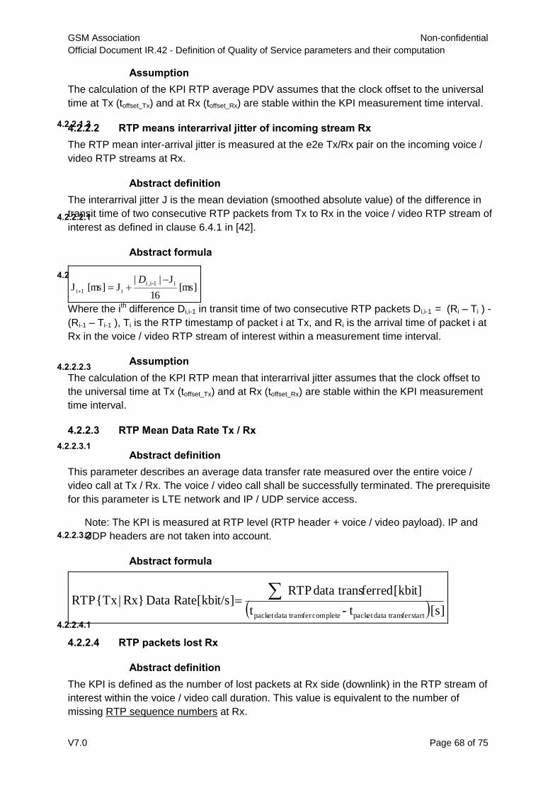
GSM Association Non-confidential
Official Document IR.42 - Definition of Quality of Service parameters and their computation
V7.0 Page 68 of 75
Assumption
4.2.2.1.3
The calculation of the KPI RTP average PDV assumes that the clock offset to the universal
time at Tx (toffset_Tx) and at Rx (toffset_Rx) are stable within the KPI measurement time interval.
4.2.2.2 RTP means interarrival jitter of incoming stream Rx
The RTP mean inter-arrival jitter is measured at the e2e Tx/Rx pair on the incoming voice /
video RTP streams at Rx.
Abstract definition
4.2.2.2.1
The interarrival jitter J is the mean deviation (smoothed absolute value) of the difference in
transit time of two consecutive RTP packets from Tx to Rx in the voice / video RTP stream of
interest as defined in clause 6.4.1 in [42].
Abstract formula
4.2.2.2.2
[ms] 16
J||J[ms] J
i1-i, i
i 1i
D
Where the ith difference Di,i-1 in transit time of two consecutive RTP packets Di,i-1 = (Ri – Ti ) -
(Ri-1 – Ti-1 ), Ti is the RTP timestamp of packet i at Tx, and Ri is the arrival time of packet i at
Rx in the voice / video RTP stream of interest within a measurement time interval.
Assumption 4.2.2.2.3
The calculation of the KPI RTP mean that interarrival jitter assumes that the clock offset to
the universal time at Tx (toffset_Tx) and at Rx (toffset_Rx) are stable within the KPI measurement
time interval.
4.2.2.3 RTP Mean Data Rate Tx / Rx
Abstract definition 4.2.2.3.1
This parameter describes an average data transfer rate measured over the entire voice /
video call at Tx / Rx. The voice / video call shall be successfully terminated. The prerequisite
for this parameter is LTE network and IP / UDP service access.
Note: The KPI is measured at RTP level (RTP header + voice / video payload). IP and
UDP headers are not taken into account.
Abstract formula
4.2.2.3.2
[s] t- t
[kbit] ferreddata trans RTP[kbit/s] Data RateRx}|{Tx RTP
startfer data transpacket completefer data transpacket
4.2.2.4 RTP packets lost Rx
Abstract definition
4.2.2.4.1
The KPI is defined as the number of lost packets at Rx side (downlink) in the RTP stream of
interest within the voice / video call duration. This value is equivalent to the number of
missing RTP sequence numbers at Rx.
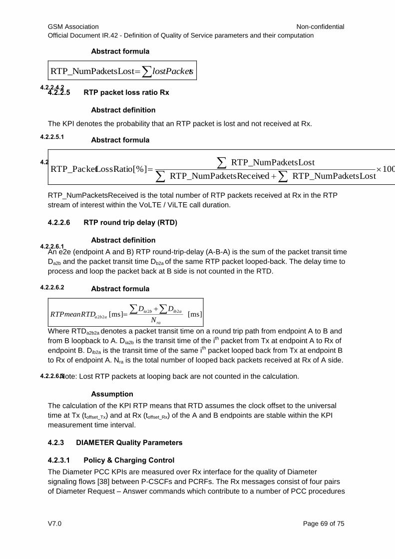
GSM Association Non-confidential
Official Document IR.42 - Definition of Quality of Service parameters and their computation
V7.0 Page 69 of 75
Abstract formula
4.2.2.4.2
slostPacketketsLostRTP_NumPac
4.2.2.5 RTP packet loss ratio Rx
Abstract definition
4.2.2.5.1
The KPI denotes the probability that an RTP packet is lost and not received at Rx.
Abstract formula
4.2.2.5.2
100 ketsLostRTP_NumPac edketsReceivRTP_NumPac
ketsLostRTP_NumPac[%] LossRatioRTP_Packet
RTP_NumPacketsReceived is the total number of RTP packets received at Rx in the RTP
stream of interest within the VoLTE / ViLTE call duration.
4.2.2.6 RTP round trip delay (RTD)
Abstract definition 4.2.2.6.1
An e2e (endpoint A and B) RTP round-trip-delay (A-B-A) is the sum of the packet transit time
Da2b and the packet transit time Db2a of the same RTP packet looped-back. The delay time to
process and loop the packet back at B side is not counted in the RTD.
Abstract formula 4.2.2.6.2
[ms] [ms] 22
22
ra
aibbia
abaN
DDRTDRTPmean
Where RTDa2b2a denotes a packet transit time on a round trip path from endpoint A to B and
from B loopback to A. Dia2b is the transit time of the ith packet from Tx at endpoint A to Rx of
endpoint B. Dib2a is the transit time of the same ith packet looped back from Tx at endpoint B
to Rx of endpoint A. Nra is the total number of looped back packets received at Rx of A side.
Note: Lost RTP packets at looping back are not counted in the calculation.
Assumption
4.2.2.6.3
The calculation of the KPI RTP means that RTD assumes the clock offset to the universal
time at Tx (toffset_Tx) and at Rx (toffset_Rx) of the A and B endpoints are stable within the KPI
measurement time interval.
4.2.3 DIAMETER Quality Parameters
4.2.3.1 Policy & Charging Control
The Diameter PCC KPIs are measured over Rx interface for the quality of Diameter
signaling flows [38] between P-CSCFs and PCRFs. The Rx messages consist of four pairs
of Diameter Request – Answer commands which contribute to a number of PCC procedures

GSM Association Non-confidential
Official Document IR.42 - Definition of Quality of Service parameters and their computation
V7.0 Page 70 of 75
for the initial provision, modification, termination of a Diameter Rx session and session
binding (a Diameter Rx session associated with a VoLTE IMS session) [38].
AA-Request (AAR) Success Ratio
4.2.3.1.1
4.2.3.1.1.1 Abstract Definition
The KPI is the probability that an AA-Request command (AAR) sent from P-CSCF via Rx
interface to PCRF results in a successful AA-Answer command (AAA) from PCRF received
by P-CSCF.
4.2.3.1.1.2 Abstract Formula
100 AAR ofNumber
Success Diameter_as Code- Result withAAA ofNumber [%] RatioSuccess AAR
RA-Request (RAR) Success Ratio
4.2.3.1.24.2.3.1.2.1 Abstract Definition
The KPI is the probability that a Re-Auth-Request command (RAR) sent from PCRF via Rx
interface to P-CSCF results in a successful RA-Answer command (RAA) from P-CSCF
received by PCRF.
4.2.3.1.2.2 Abstract Formula
100 RARofNumber
Success Diameter_as Code- Result with RAAofNumber [%] RatioSuccess RAR
ST-Request (STR) Success Ratio 4.2.3.1.3
4.2.3.1.3.1 Abstract Definition
The KPI is the probability that a Session-Termination-Request command (STR) sent from P-
CSCF via Rx interface to PCRF results in a successful ST-Answer command (STA) from
PCRF received by P-CSCF.
4.2.3.1.3.2 Abstract Formula
100 STR ofNumber
Success Diameter_as Code- Result withSTA ofNumber [%] RatioSuccess STR
AS-Request (ASR) Success Ratio
4.2.3.1.4
4.2.3.1.4.1 Abstract Definition
The KPI is the probability that an Abort-Session-Request command (ASR) sent from PCRF
via Rx interface to P-CSCF results in a successful AS-Answer command (ASA) from P-
CSCF received by PCRF.
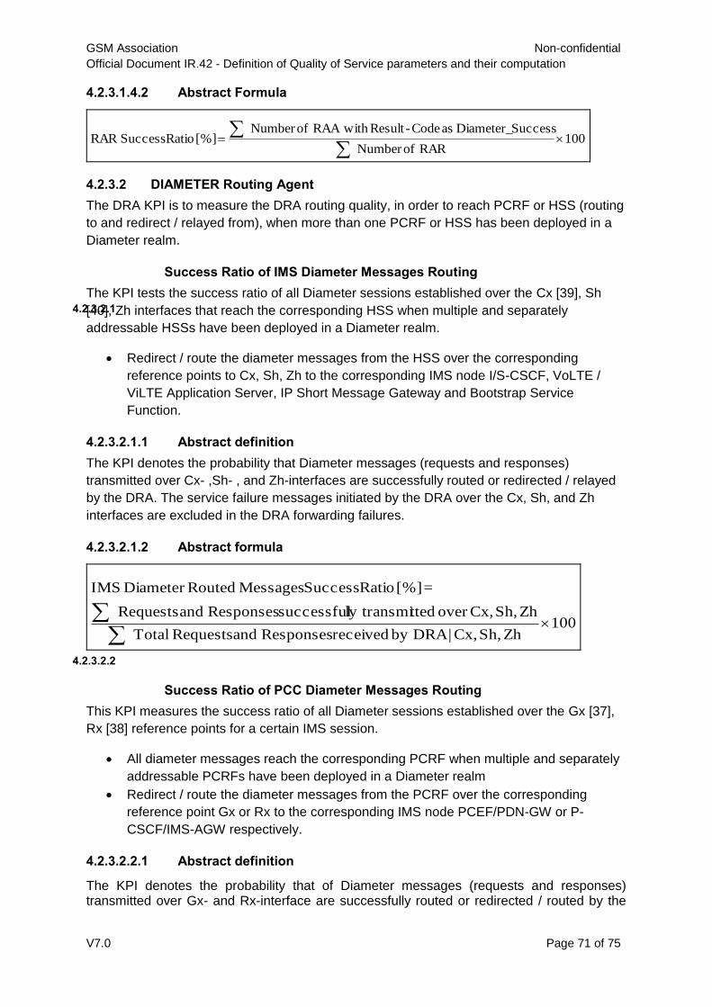
GSM Association Non-confidential
Official Document IR.42 - Definition of Quality of Service parameters and their computation
V7.0 Page 71 of 75
4.2.3.1.4.2 Abstract Formula
100 RARofNumber
Success Diameter_as Code- Result with RAAofNumber [%] RatioSuccess RAR
4.2.3.2 DIAMETER Routing Agent
The DRA KPI is to measure the DRA routing quality, in order to reach PCRF or HSS (routing
to and redirect / relayed from), when more than one PCRF or HSS has been deployed in a
Diameter realm.
Success Ratio of IMS Diameter Messages Routing
4.2.3.2.1
The KPI tests the success ratio of all Diameter sessions established over the Cx [39], Sh
[40], Zh interfaces that reach the corresponding HSS when multiple and separately
addressable HSSs have been deployed in a Diameter realm.
Redirect / route the diameter messages from the HSS over the corresponding
reference points to Cx, Sh, Zh to the corresponding IMS node I/S-CSCF, VoLTE /
ViLTE Application Server, IP Short Message Gateway and Bootstrap Service
Function.
4.2.3.2.1.1 Abstract definition
The KPI denotes the probability that Diameter messages (requests and responses)
transmitted over Cx- ,Sh- , and Zh-interfaces are successfully routed or redirected / relayed
by the DRA. The service failure messages initiated by the DRA over the Cx, Sh, and Zh
interfaces are excluded in the DRA forwarding failures.
4.2.3.2.1.2 Abstract formula
100Zh Sh, Cx,| by DRA received Responsesand RequestsTotal
Zh Sh, Cx,over ttedly transmisuccessful Responsesand Requests
=[%] RatioSuccess MessagesRouted Diameter IMS
Success Ratio of PCC Diameter Messages Routing
4.2.3.2.2
This KPI measures the success ratio of all Diameter sessions established over the Gx [37],
Rx [38] reference points for a certain IMS session.
All diameter messages reach the corresponding PCRF when multiple and separately
addressable PCRFs have been deployed in a Diameter realm
Redirect / route the diameter messages from the PCRF over the corresponding
reference point Gx or Rx to the corresponding IMS node PCEF/PDN-GW or P-
CSCF/IMS-AGW respectively.
4.2.3.2.2.1 Abstract definition
The KPI denotes the probability that of Diameter messages (requests and responses) transmitted over Gx- and Rx-interface are successfully routed or redirected / routed by the

GSM Association Non-confidential
Official Document IR.42 - Definition of Quality of Service parameters and their computation
V7.0 Page 72 of 75
DRA. The service failure messages initiated by the DRA over the Gx and Rx interfaces are excluded in the DRA forwarding failures.
4.2.3.2.2.2 Abstract formula
100 RxGx,| by DRA received Responsesand RequestsTotal
RxGx,| ttedly transmisuccessful Responsesand Requests
=[%] RatioSuccess RoutedMessages Diameter PCC

GSM Association Non-confidential
Official Document IR.42 - Definition of Quality of Service parameters and their computation
V7.0 Page 73 of 75
Annex A Examples for measuring trigger points
A.1 SMS-Service:
A.1.1 Layer 3 Messages:
Start SMS Service Attempt: Generating random access (chan_request
SDCCH) at mobile equipment
Successful SMS Service
Attempt
Receiving cp_data (rp_ack) at mobile equipment
Receiving SMS on Mobile
Equipment 2:
Receiving cp_data (rp_ack) at mobile equipment

GSM Association Non-confidential
Official Document IR.42 - Definition of Quality of Service parameters and their computation
V7.0 Page 74 of 75
Annex B Document Management
B.1 Document History
Version Date Brief Description of Change Approval Authority
Editor / Company
0.1.0 January 5th,2001
First draft of document for IREG QoS WP discussion
0.2.0 March 30th,2001
Second draft of document for IREG QoS WP e-mail discussion
0.3.0 27 Apr 2001
Third draft for IREG QoS workshop including Data Services
1.0.0 10 Jul 2001
First stable Version for chapters Telephony, SMS
2.0.0 11 Sep 2001
Document for approval at IREG #41 and GSMA with a document classification of “Unrestricted – Public”
3.0.0 21 Sep 2001
Document approved by GSMA
3.0.1 30 Apr 2002
Parameter Completion Rate SMS circuit switched added
3.0.2 14 May 2002
Parameter for CSD and PSD Data Services added
3.1.0 17 Jun 2002
Document for approval at IREG #43 and GSMA with a document classification of "Unrestricted – Public"
3.2.0 10 Oct 2002
Changes in chapters 2.4, 2.5-2.7 approved by QoSWP Meeting #8, 02.10.2002
3.2.1 10 Feb 2003
Editorial changes in chapters 2.5-2.7
3.3 16 Apr 2007
IREG doc 52_037 incorporated “Addition of the new QoS parameter definitions”
3.4 10 Aug 2009
Signal doc 43_009 incorporated “Changing computation method for speech quality from MOS to PESQ ”
Marko Onikki, TeliaSonera
3.5 9 Dec 2009
Incorporate outputs of Global roaming Quality project
IREG#55, EMC#79
Marko Onikki, TeliaSonera
3.6 4 Jan 2011 Signal Docs 49_16 and 50_009 incorporated
IREG Signal Marko Onikki, TeliaSonera
4.0 6 Jun 2011 Signal Docs 53_009 incorporated IREG Signal
Marko Onikki, TeliaSonera
5.0 May 22th,
2015 Incorporated CR1001 and CR1002
IREG Marko Onikki TeliaSonera
6.0 November 5
th,2015
Incorporated CR1003 NG
Marko Onikki TeliaSonera
7.0 18 October 2016
CR1004 Add VoLTE and ViLTE roaming quality parameters
NG Marko Onikki Telia Company

GSM Association Non-confidential
Official Document IR.42 - Definition of Quality of Service parameters and their computation
V7.0 Page 75 of 75
B.2 Other Information
Feedback
It is our intention to provide a quality product for your use. If you find any errors or omissions,
please contact us with your comments. You may notify us at [email protected]
Your comments or suggestions & questions are always welcome.
Type Description
Document Owner GSMA NG
Editor / Company Marko Onikki / Telia Company


![[Type text] - 5G Americas · 2019-07-25 · VOLTE AND VILTE GSMA PRD IR.92 addresses IMS’s basic capabilities and supplementary services for telephony, and how these service capabilities](https://static.fdocuments.us/doc/165x107/5e91ad98a3fbec6f7f6b25f6/type-text-5g-americas-2019-07-25-volte-and-vilte-gsma-prd-ir92-addresses.jpg)