Defense Technical Information Center Compilation …SM) 14-1 F-15 Structural Life Enhancement Jeff...
13
UNCLASSIFIED Defense Technical Information Center Compilation Part Notice ADP014070 TITLE: F- 15 Structural Life Enhancement DISTRIBUTION: Approved for public release, distribution unlimited Availability: Hard copy only. This paper is part of the following report: TITLE: Ageing Mechanisms and Control. Specialists' Meeting on Life Management Techniques for Ageing Air Vehicles [Les mecanismes vieillissants et le controle] [Reunions des specialistes des techniques de estion du cycle de vie pour vehicules aeriens vieillissants] To order the complete compilation report, use: ADA415672 The component part is provided here to allow users access to individually authored sections of proceedings, annals, symposia, etc. However, the component should be considered within -he context of the overall compilation report and not as a stand-alone technical report. The following component part numbers comprise the compilation report: ADP014058 thru ADP014091 UNCLASSIFIED
Transcript of Defense Technical Information Center Compilation …SM) 14-1 F-15 Structural Life Enhancement Jeff...

UNCLASSIFIED
Defense Technical Information CenterCompilation Part Notice
ADP014070TITLE: F- 15 Structural Life Enhancement
DISTRIBUTION: Approved for public release, distribution unlimitedAvailability: Hard copy only.
This paper is part of the following report:
TITLE: Ageing Mechanisms and Control. Specialists' Meeting on LifeManagement Techniques for Ageing Air Vehicles [Les mecanismesvieillissants et le controle] [Reunions des specialistes des techniques deestion du cycle de vie pour vehicules aeriens vieillissants]
To order the complete compilation report, use: ADA415672
The component part is provided here to allow users access to individually authored sectionsof proceedings, annals, symposia, etc. However, the component should be considered within-he context of the overall compilation report and not as a stand-alone technical report.
The following component part numbers comprise the compilation report:ADP014058 thru ADP014091
UNCLASSIFIED

(SM) 14-1
F-15 Structural Life Enhancement
Jeff L. McFarlandThe Boeing Company
MC S 1066420PO Box 516
St. Louis, Missouri 63166, USA
Dr. Rigoberto PerezThe Boeing Company
MC S1021322PO Box 516
St. Louis, Missouri 63166, USA
Abstract
This paper summarizes the effort funded by the United States Air Force Reseairch Laboratory at WrightPatterson Air Force Base to identify the problem structural areas on the F-15 and recommend appropriatesolutions with the development of new technology. Recent modifications to the F-15 airframe structurehave taken place or are under consideration to reduce honeycomb water corrosion, reduce maintenancecosts, quickly produce spares, provide technology demonstration for future aircraft, and eliminating/reducing maintenance, including NDI inspections and problem fatigue cracking issues. Therecommendations in the plan address solutions that can be integrated into an overall life extension planfor fighter aircraft.
1.0 INTRODUCTION
Fatigue and corrosion damages are issues in the USAF aging fighter aircraft fleet. Periodic inspectionsand replacements of the damaged components have solved many of these problems, but this approach isexpensive and significantly reduces aircraft availability. In addition, damage can reoccur requiring thesame repair to be performed several times. Alternative structural life enhancement technologies existwhich offer more efficient solutions.
The F- 15 has provided a reliable and robust airframe, even though first flight was nearly thirty years ago.The material and design technology used for this airframe was based on technology available in the latesixties, where the extensive use of titanium was considered a major technological change. The addition ofthe F-15E into the USAF inventory in the mid-eighties incorporated the first new structural technology,BLATS, Built-up Low-cost Advanced Titanium Structure. And, while no major structural fatigue issueshave surfaced in thirty years of operation, the F- 15 aircraft has experienced secondary structural crackingdue to buffet and sonic fatigue at various locations along with secondary structure cracking due tomaneuver loading. Additionally, corrosion in secondary and some aluminum primary structure hasbegun to surface, creating maintenance and logistics issues. Several recent structural modifications to theF-15 have taken place, or are under consideration: reducing honeycomb water corrosion; reducing thecost of spare parts, substitutions to quickly produce spares; providing technology demonstrators for futureaircraft; and eliminating/reducing maintenance, including NDI inspections and problem fatigue crackingissues. To assess the remaining airframe issues, a survey was taken and those components that couldbenefit from structural life enhancement technologies were identified for further study.
Paper presented at the RTO A VT Specialists' Meeting on 'Life Management Techniques./br Ageing Air Vehicles",held in Manchester, United Kingdom. 8-11 October 2001, and published in RTO-MP-079(II).
(SM) 14-2
Included in this paper are the results of the study conducted for the United States Air Force ResearchLaboratory at Wright-Patterson Air Force Base, to identify the problem areas on the F- 15 and determineappropriate solutions. This study provided an assessment of available structural life enhancementtechnologies and was focused on technologies that can be applied on existing structure. In addition to thisstudy, recent technological upgrades to the F-15 as spares, technology demonstrators, corrosionprevention enhancements, or resolutions to fatigue areas of concern have been included.
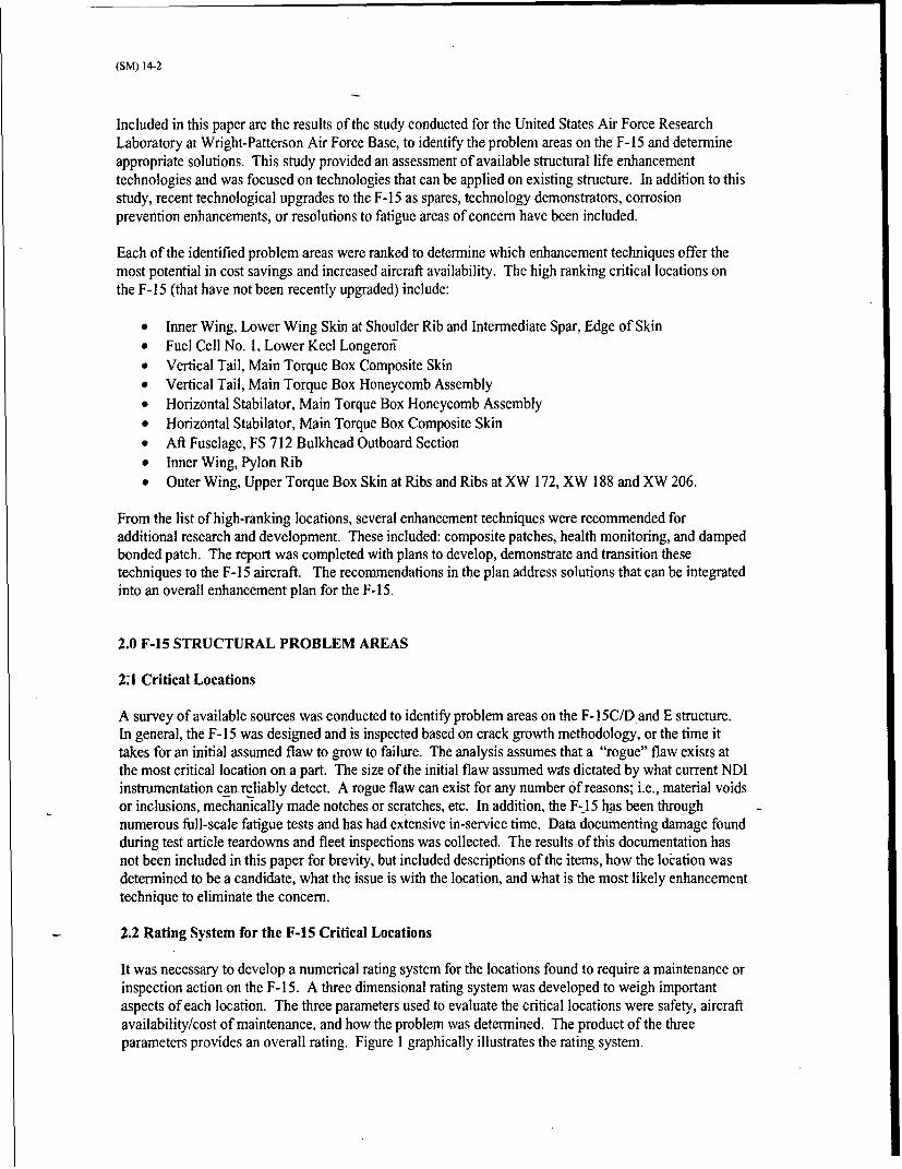
Each of the identified problem areas were ranked to determine which enhancement techniques offer themost potential in cost savings and increased aircraft availability. The high ranking critical locations onthe F-15 (that have not been recently upgraded) include:
"* Inner Wing, Lower Wing Skin at Shoulder Rib and Intermediate Spar, Edge of Skin"* Fuel Cell No. 1, Lower Keel Longeroff"* Vertical Tail, Main Torque Box Composite Skin"* Vertical Tail, Main Torque Box Honeycomb Assembly"* Horizontal Stabilator, Main Torque Box Honeycomb Assembly"* Horizontal Stabilator, Main Torque Box Composite Skin"* Aft Fuselage, FS 712 Bulkhead Outboard Section"* Inner Wing, Pylon Rib"* Outer Wing, Upper Torque Box Skin at Ribs and Ribs at XW 172, XW 188 and XW 206.
From the list of high-ranking locations, several enhancement techniques were recommended foradditional research and development. These included: composite patches, health monitoring, and dampedbonded patch. The report was completed with plans to develop, demonstrate and transition thesetechniques to the F-15 aircraft. The recommendations in the plan address solutions that can be integratedinto an overall enhancement plan for the F-15.
2.0 F-15 STRUCTURAL PROBLEM AREAS
2:1 Critical Locations
A survey of available sources was conducted to identify problem areas on the F- 15C/D and E structure.In general, the F- 15 was designed and is inspected based on crack growth methodology, or the time ittakes for an initial assumed flaw to grow to failure. The analysis assumes that a "rogue" flaw exists atthe most critical location on a part. The size of the initial flaw assumed was dictated by what current NDIinstrumentation can-reliably detect. A rogue flaw can exist for any number of reasons; i.e., material voidsor inclusions, mechanically made notches or scratches, etc. In addition, the F-I5 has been throughnumerous full-scale fatigue tests and has had extensive in-service time. Data documenting damage foundduring test article teardowns and fleet inspections was collected. The results of this documentation hasnot been included in this paper for brevity, but included descriptions of the items, how the location wasdetermined to be a candidate, what the issue is with the location, and what is the most likely enhancementtechnique to eliminate the concern.
2.2 Rating System for the F-15 Critical Locations
It was necessary to develop a numerical rating system for the locations found to require a maintenance orinspection action on the F-15. A three dimensional rating system was developed to weigh importantaspects of each location. The three parameters used to evaluate the critical locations were safety, aircraftavailability/cost of maintenance, and how the problem was determined. The product of the threeparameters provides an overall rating. Figure 1 graphically illustrates the rating system.

(SM) 14-3
2.2.1 Safety Category - Safety-of-flight criticality is the, single most important aspect of all weightingparameters. The F-i 5 bases inspections on crack growth methodology, or the time it takes an initial flawto grow to failure. For this category a rating of"I" was assigned to durability critical structure and avalue of"2" was assigned to safety-of-flight critical structure. The safety-of-flight criterion, with initialflaws placed at the most critical locations and oriented in the most critical orientations, was defined toprevent failure from a rogue flaw.
2.2.2 How the Problem was Determined - All critical locations fell into one of three categories basedon how the problems were determined; by analysis, by full scale fatigue testing, or by in-service failures.Analysis is the most common method of determining critical locations. This was used as the baseline anda value of one was assigned to critical locations found in this manner. Full scale fatigue testing wasassigned a value of one and a half since failures found during testing or in the subsequent tear downsimulate cracking that could occur in service. Loading tends to be more realistic than by analysis sinceloading will distribute differently than a coarse Finite Element Model might indicate. In-service failureswere assigned a value of two. Failure during actual usage provides the best and clearest picture of howaircraft are used operationally.
2.2.3 Aircraft Availability/Cost - Three basic ratings (low=T, medium=2 and high=3) were assigned toall critical locations based on aircraft availability and cost. Aircraft availability refers to the impact ofpart maintenance on down time or mission capability and represents the effect of repeat repairs on thesame component. Cost not only includes the part, but all maintenance operations. Often, replacing a"buried" part will result in a cost to the customer that far exceeds the basic part cost if major disassemblyis required. Availability and cost were combined into a single parameter because of the close correlationbetween them. An expensive and difficult repair can lead to longer downtime. However, lower costrepairs can also cause significant downtime if parts or equipment are not available. In general, the effectof maintenance on aircraft availability is greater during field repairs.
FIGURE 1
RATING PARAMETERS FOR F-15 CRITICAL LOCATIONS
SAFETY CATEGORY
2 Safety-of-Flight
1 Durability
AVAILABILITY PROBLEM/1 Analysis DETERMINED
BYSMedium , 1. est .
High 3, "2 In-Service
3.0 STRUCTURAL LIFE ENHANCEMENT TECHNIQUES
3.1 Life Enhancement Techniques - State of the Art
The following subsections describe the current state of the art of various enhancement techniquesavailable. Particular aspects of these techniques are classified as "mature", "near general application", or"needs additional development". The criteria for classification are as follows.

(SM) 14-4
3.1.1 Mature - Techniques under this category are in general use on operational aircraft. Procedures arewell documented in Tech Order Manuals, for example. Analysis methods associated with the technologyare in general use within industry. A brief listing includes:
3.1.1.1 Cold Working - Through this process, a hole is radially expanded resulting in circumferentialcompressive residual stresses. The compressive stresses delay crack initiation and can retard crackgrowth. Structural enhancements applications of parts installed on the aircraft have been improved by thedevelopment of one-sided cold working methods and rivetless nutplates [3.1]. Additional work isnecessary to provide full analytical benefits from cold working.
3.1.1.2 Interference Fit Fasteners - These types of fasteners increase fatigue life by reducing the stressconcentration of the fastener hole and by introducing beneficial compressive residual stresses around thehole wall. There are three types of interference fit fasteners that can be used to improve fatigue life: solidrivets, pin and collar fasteners (hi-loks and lockbolts) and tapered fasteners (taper-loks). As with coldworking additional work is necessary to provide full analytical benefits from cold working.
3.1.1.3 Shot Peening - The shot peening. This process adds beneficial residual stresses for increasedfatigue resistance. The material being peened must be considered in choosing shot peening intensity, shotsize, shot hardness, and coverage. Shot peening is primarily used in retarding crack initiation because thedepth of the residual stresses is too shallow (up to 0.03 in.) to affect crack growth. Care must be taken notto cause surface damage from over peening. High strength steel landing gears are a major application inaircraft. Recent developments in this area include the use of shot peening to search for inter-granularcorrosion and exfoliation [3.2].
3.1.1.4 Fleet Monitoring - Fatigue tracking and usage monitoring programs have evolved with each newweapon system and have ranged from tracking of flight hours to multi-channel recorders and strain gages.Because of conservatism, tracking flight hours can result in premature retirement or in maintenanceperformed more frequently than necessary. Aircraft flown under very severe missions can exceed thedesign usage and accumulate damage more rapidly than expected. To improve the accuracy of aircrafttracking programs, counting accelerometers were installed in various aircraft models. These countingaccelerometer-based systems can be classified as a second generation tracking system, since theyfollowafter the simpler flight hour based method. The need for further improvements in accuracy led to thedevelopment of the third generation tracking systems based on multi-channel recorders to track additionalparameters. Fourth generation systems have incorporated strain gages to more directly compute stressesin the tracked components.
It is possible to upgrade fatigue-tracking systems to obtain more accurate data. As mentioned earlier,more accuracy reduces conservatism and can result in longer inspections intervals or longer operationallife. However, the cost of a fatigue tracking system upgrade can be prohibitive for some fleets. One ofthe reasons for-the high expense is the cost of integrating a new system with the existing hardware andsoftware. A stand-alone health monitoring system that can be installed without affecting other aircraftsystem offers many advantages.
3.1.2 Near general application - A technique in this classification has been used on a limited number ofoperational aircraft or has been applied on only specific aircraft types, but is not in general use on theUSAF fleet. Process is documented, but requires engineering supervision. Analyses methods associatedwith the technology have been verified, but are in use by a limited segment of industry (one contractor,for example).
3.1.2.1 Corrosion Prevention - Grinding to remove damaged material or part replacements are standardmethods for repairing corrosion. Coatings are needed to protect the part from subsequent corrosion withthe goal of restoring the required operational life or in some cases extend the life. One of the major issuescurrently affecting corrosion control is the effect of non-chromated primers and conversion coats. Thesematerials will see increased use as conventional coatings containing hexavalent chromium are replaced.

(SM) 14-5
3.1.2.2 Damped Bonded Patch - Fatigue from vibratory loads is a common cause of structural failure infighter aircraft. The F-15 lower fuselage skin has been affected by acoustic fatigue, while the outer wingupper skins have experienced buffet. Constrained viscoelastic layer damping treatments are one methodto reduce vibration.
A more effective method being evaluated combines damping within a composite material patch. Thepatch can be bonded very effectively to the structure while containing the necessary damping. Under acompany sponsored IRAD project, Boeing developed damped composite patches to reduce acousticresponse on the F- 15 [3.3]. These damping patches have flown on lower fuselage skins and doors of twoF- 15s resulting in up to a 69% reduction in vibration.
3.1.2.3 Composite Patches - Composite patch repairs of cracked metallic structure have been appliedextensively by the United States Air Force Warner Robins-Air Logistics Center on the C-141 and C-130fleet. Several patches have also been installed on B-52 and F-16 aircraft. Under United States Air Forcesponsorship, Boeing is currently performing the Composite Repair of Aircraft Structures (CRAS)program. The program objectives are to: (1) fill in gaps in the existing composite repair patchtechnology, and (2) promote the technology with new users such as the F-15.
An application for composite patches is on the front wing spar on the F- 15 aircraft. Fatigue cracks havebeen found in the web of this spar emanating from a conduit hole in earlier F-15 models. Bolted repairshave been developed for this problem, and the component was redesigned in the F-1 5E. However,inspections are still required to detect if cracks are present.
Under the CRAS program, Boeing has developed a pre-emptive patch for this location. The patchrestores the required crack growth life, reduces inspections and avoids drilling of holes required for boltedrepairs. Laboratory tests are in work using two machined specimens representing the F-15 spar conduithole location. The first specimen will contain an initial crack and will be tested without a patch in orderto obtain baseline data. The second specimen will also have a crack started, but this time the specimenwill be repaired with a composite patch. Both specimens will be fatigue tested to failure to verify the lifeimprovement expected with the composite patch. Conventional strain gages will be used in both tests. Ademonstration of the patch on an operational F-l15 is also planned.
Once these tests are completed the technology will be ready for additional applications on the F-15. Onearea where additional development is needed is in health monitoring systems that result in a "smart patch"capable of detecting disbonds: Such a system would promote applications in areas difficult to inspect.
3.1.2.4 Grid-Lock* - Grid-lock*, patent held by BF Goodrich, is on the verge of becoming a maturetechnology. The F-15 is in the process of eliminating all honeycomb structure in preference of Grid-lock* to eliminate the inherent corrosion issues of honeycomb. Grid-lock* utilizes a unique method ofconstruction by precise machining of tongue-in-groove channels, adhesive bonding, and designingstructure such that each joint is reacted in shear. The F-15 has completed fatigue testing of the aileron(subjected to buffet) and is in the process of testing a wing tip to validate usage in all locations.
3.1.2.5 Laser Formed Titanium - Laser formed titanium, developed by AeroMet Inc. (Eaden PrairieMinn., USA) is another process that is on the verge of becoming a mature technology. The F-15 is in theprocess of manufacturing spares developed from laser formed titanium to lower overall part cost andreduce overall cycle time. Laser formed titanium is developed by depositing a layer of pre-alloyedtitanium powder on a target plate with a C02 laser. From this target plate flanges, stiffeners, etc. are builtup. Final machining can eliminate this target plate if the target plate properties are not desired.
* Grid-lock is a registered trademark

(SM) 14-6
3.1.2.6 Material Substitution - The F-15 is currently under consideration to replace aluminum parts thatare found corroded with the newly developed aluminum 7055, produced by Alcoa. Lower longerons andskins under the fuel cells and the flap hinge beams are regularly found and replaced for corrosion.Unfortunately, the replacement material used is the same as was the original design. The new material isnow under investigation for verification of material properties and is hoped to replace all 7000 series partsin the future.
3.1.3 Needs additional development - Technologies in this category are still in the laboratory stage orhave been demonstrated on aircraft as part of an R&D project. This category may also include moreestablished methods where technology gaps exist. Analysis methods may exist, but need verification.
3.1.3.1 - Advanced Riveting Technology - Force controlled riveting can result in longer fatigue life thanwith conventional displacement controlled riveting. The benefit is caused by greater compressive residualstresses surrounding the hole. The residual stresses lead to crack growth retardation at the riveted hole[3.4].
3.1.3.3 Active Vibration Suppression - Buffet is a major source of fatigue damage on fighter aircraftempennage structure. Two methods used in developing a solution to this problem include "smart"materials and active rudder control.
"Smart" materials distributed over vertical tail structure have been demonstrated to control structuralvibration modes [3.5 - 3.9]. The results from these programs show that piezoelectric driven skins canreduce buffet loads at all flight conditions. However, power requirements and durability have limitedpiezoelectric system applications.
The RANN Corporation evaluated the use of active rudder control to mitigate buffet response on the F-I 5and F/A- 18 [3.5]. Boeing completed a wind tunnel experiment using a 15% scaled F/A-1 8 model todemonstrate the use of the rudder to control vertical tail buffet response [3.10]. The vertical tail wasdesigned with a movable rudder that was controlled using a hydraulic actuator. RMS bending momentreduction of up to 42% were achieved. These reduced loads can improve the dynamic fatigue lives byfactors of 4 to 10.
3.1.3.4 Laser Shock Processing - Laser shock processing, also known as laser shot peening, is a methodfor inducing surface beneficial residual stresses [3.11]. Energy absorbed from a laser pulse generateshigh shock pressure over the surface of the metal part. Energy absorption is enhanced with black paint onthe metal surface. The energy is concentrated near the surface with a layer of water. Laser shock caninduce residual stresses deeper than with regular shot peening (up to 0.04 in.), and it avoids surfacedamage. Applications of this method include high value components such as jet engine blades.
3.1.3.5 Friction Stir Welding - Friction stir welding is a process of welding by the rotation of a threadedcylindrical pin tool [3.121. First, the rotating pin tool penetrates the material at a location where a weld isrequired. The material reaches the plastic state because of the frictional heat generated by the rotatingtool. Finally, the rotating tool moves along the weld line, stirring the material on both sides of the weld.This results in a bond between the parts being joined. The process is in production use and newapplications in complex airframe structure are in development [3.13]. One potential Service LifeEnhancement application is in repair of cracked structure.
3.1.3.6 Health Monitoring - Two areas of health monitoring are the active detection of cracking and theactive detection of corrosion.
For example, during a F-15 full-scale fatigue test, a strain gage was located on a wing spar cap near acrack location. Changes in strain values recorded during the test were correlated to the growth of the

(SM) 14-7
crack. Other methods use acoustic emissions for monitoring cracks and smart fasteners for detectingdamage in bolted joints.
Corrosivity measurement is another area of health monitoring. A sensor unit has been developed by USNto record moisture and temperature [3.13]. The unit is self contained and small (4.1 cm x 4.7 cm x 1.7 cmexcluding the sensor element). Data is downloaded remotely with a handheld data-gathering unit at arange of 40 m. These types of cirrosivity sensorsjust measure the environment, but not actual corrosion.
Composite patches are an effective method of repairing cracked or corroded structure, but the patches areonly good as long as they remain bonded to the structure. If done properly, modem surface preparationtechniques result in very strong bonds. However, patches installed in substructure cannot be easilyinspected for disbonds. Repaired primary structure must be capable of carrying limit load in the eventthat the patch falls off.
To address these issues, health monitoring systems that result in a "smart patch" capable of detectingdisbonds are in development. One project uses strain gages and piezoelectric sensors installed on thepatch to monitor the ratio of patch strain to component strain [3.14].
The damage dosimeter is an example of a stand-alone system for measuring the environment at a specificlocation. The dosimeter was designed to record time, temperature and dynamic data from three straingages. It is compact (7.5 in. x 4.5 in. x 1.25 in. plus a battery pack), and does not require aircraft poweror cooling. A dosimeter can be installed easily in an aircraft to record data in areas affected by dynamicfatigue caused by high acoustics or buffet, for example. Data can be downloaded from the aircraft byconnecting a laptop computer to the dosimeter. Once the needed data is obtained, the dosimeter isremoved.
3.2 Enhancement Techniques - F-15 Usage
3.2.1 Fastener Holes - The basic choice for critical fastener holes, if no previous enhancement had beenincorporated, was to use interference fit fasteners or cold working. These improvements are mature andhave shown definite improvements over standard holes. Installation of either procedure is straightforwardand the both processes are well documented. Analysis of either enhancement is conservative anddevelopment of more sophisticated analytical tools can provide for increased inspection intervals.
3.2.2 Composites - Composite patches were chosen in several situations with different goals in mind.For locations where buffet, noise, or vibrations are problems, "Active Vibration Suppression" techniquesor "Damped Bonded Patch" techniques are appropriate. In many cases some form of these techniqueshave been applied with varying amounts of success. In many early applications the suppressants havedisbonded and been of limited use. Application of more robust bonding is required to build confidencethroughout the fleet. For locations with high stresses, a composite patch to reduce localized stress peaksis desired. Currently, use of bonded patches is limited in nature and has not been used as an active fightertechnique to eliminate "hot" spots due to unknowns associated with bonded patches. The need for thisconfidence is necessary as bolted repairs can create as many problems as they solve with the addition offastener holes. "Smart" patches may be one method of obtaining confidence in bonded patches. TheUSAF and industry are making major break throughs in this area and practical application of bondedpatches in key locations is needed to spread this technology.
3.2.3 Peening - Shot Peening and Laser Shock Processing were mentioned in a very limited fashion forcritical locations. Since the F- 15 inspection system is based on rogue flaw theory, these two methodshave limited practical influence, as the improvements are so surface localized. In practicality eithertechniques would improve the economic life of the aircraft. Rogue flaws generally do not exist andcracking initiates, in almost all cases, on the surface of the part. A layer of beneficial residual stresseswould retard the initial crack growth in the part.

(SM) 14-8
3.2.4 Health Monitoring - Health monitoring was listed fairly extensively in the Wright Patterson study.Corrosion determination is interdependent with moisture collection. Therefore, a specific schedule cannotbe defined since it is impossible to know when moisture will be trapped. With the use of a system todetect trapped moisture, corrosion can be prevented by a maintenance action to remove the accumulatedwater (for example, cleaning of plugged drain holes). The second health monitoring system needed is thefull development of instrumentation to detect disbonds in composite structure or detection of cracksgrowing in areas of high stresses. As mentioned earlier, these systems exist but have not beenimplemented to any degree.
3.2.5 Spare and Replacement Parts -
3.2.5.1 Material Substitution - For corrosion, material substitution appears to be the optimum choice.For the F-15 lower longerons and skins, the use of 7055 may potentially provide enhanced corrosionprotection. For the F- 15 wing pylon, a material substitution from aluminum to titanium not onlyeliminates corrosion, but also eliminates issues of fatigue cracking and static overloads. Simple coatingshave not offered substantial and sufficient protection from corrosion since they can be worn off or scrapedaway during normal operation and maintenance.
3.2.5.2 Laser Formed titanium - Laser formed titanium offers availability of titanium spare/replacementparts in a much more rapid procurement fashion. Lead times to obtain forgings can be cut in half with asignificant control on costs.
3.2.5.3 Grid-Lock* - Grid-lock* helps to eliminate the water entrapment and subsequent corrosionproblems seen in honeycomb structure. Use of corrosion resistant materials, i.e., 7055 aluminum, couldbe used to enhance these benefits. Honeycomb is extremely efficient, but not at the cost of the currentmaintenance burden.
4.0 SLE TECHNOLOGY DEVELOPMENT, DEMONSTRATION AND TRANSITION
For each "Near General Application" and "Needs Additional Development" technology, developmentsteps to fill technology gaps are recommended. These are followed by demonstration plans to ensure thetechnology is ready for transition into the fleet. In most cases, a demonstration program should scale upthe test specimens to represent actual aircraft structure.
The demonstrations should include flight tests with the corresponding aircraft to increase the maturitylevel and confidence in the new methods.
The following subsections describe a strategy for defining, developing, and demonstrating eachenhancement technology and transitioning theses technologies to the USAF fleet.
4.1 Composite Patches
Additional work should focus on expanding technologies developed under CRAS and related programs.Specific areas include thick structure, complex geometry, repair of stress corrosion cracking and pre-emptive patches. Pre-emptive patches, installed before cracks initiate, do not need to be as robust aspatches used in repair of cracked structure. They can have fewer plies, and because less stiffness isrequired, alternatives to boron/epoxy can be used. Analysis of these patches is needed to determine thestresses in the un-cracked structure, and predict the number of flight hours to initiate a crack. Thecalculated stresses are also used to perform damage tolerance assessments with an assumed initial crack(typically 0.05 inch long). New analysis methods should be verified with coupon and element tests priorto demonstration in actual aircraft parts. The tests should also evaluate the effect of temperature on theadhesive.

(SM) 14-9
Another area where additional development is needed is in health monitoring systems that result in a"smart patch" capable of detecting disbonds. Because several programs are already focusing on sensors,further work on new sensor development is not necessary. Instead, additional work is needed on theintegration and demonstration of this technology.
Therefore, a demonstration program on "smart pre-emptive patches" is recommended. Laboratoryspecimens should be instrumented with strain gages to verify stress analyses and should represent actualstructure. In addition to strain, patch temperature measurements need to be demonstrated. Patches withdisbonds of various sizes will help verify the ability of the sensors to detect different levels of damage.Flight tests following the laboratory demonstrations are suggested.
4.2 Health Monitoring
In addition to the smart patch mentioned in the previous section, several high-ranking locations on the F-15 were identified as candidates for health monitoring. The main source of these problems is waterentrapment. Clogged drain holes can lead to water entrapment and resulting corrosion. Freezing of waterwithin honeycomb cells can cause disbonds between the skin and the honeycomb. Sensors that signalwhen water is trapped could help prevent corrosion and disbonds in the identified locations by alertingmaintenance personnel.
Sensor development has been conducted in other programs, and any additional work should focus on theintegration and demonstration of this technology. This work should define how to use the sensors. Forexample, an indication of water may signal nothing more than normal drainage and would result .in a falsealarm. However, water present for an extended period may be caused by an actual clogged drain hole.The demo should establish the criteria to identify real problems using specimens representing actualstructural configurations. The F-15 locations for sensing when water is contained in honeycombstructures are:
Vertical Tail, Main Torque Box Composite SkinVertical Tail, Main Torque Box Honeycomb AssemblyHorizontal Stab, Main Torque Box Honeycomb AssemblyHorizontal Stab, Main Torque Box Composite Skin
Sensors should be installed on operational aircraft to test their capacity to detect water in real conditions.The sensors should be used to measure drainage time periods. In some cases aircraft drain holes shouldbe plugged to simulate clogged drainage. Tests should include temperature changes to evaluate thesensors in the presence of frozen water.
4.3 Interference Fit Fasteners/Cold working
One of the main technology gaps is the lack of a robust analysis methodology that accounts for thebeneficial residual stresses resulting from this technique. This is especially the case with interference fitfasteners and hole propping.
NASA Langley Research Center has been developing analysis methods in this area. In cooperation withNASA, the analysis methodology should be completed and a test program defined to verify the analysis.Vendors associated with this technology should help with test plan definition. The test plan needs to coverthe following:
Baseline open hole specimensCold worked holesTight fit fasteners with no interferenceInterference fit fasteners (hi-loks and lockbolts)Tapered fasteners (taper-loks)

(SM) 14-10
Sleeve-boltsCombined cold worked hole with fastenersTitanium and steel fastenersSingle and double lap specimens with titanium, aluminum and combined layersConstant amplitude and spectrum loading
During fabrication of the specimens, procedures for verifying the level of interference need to bedemonstrated. The vendors should help in developing these procedures. Once the analysis methods aredeveloped and verification tests completed, companies associated with this technology should help in theevaluation of results. The demonstration program should include tests with specimens representing actualaircraft structure.
4.4 Damped Bonded Patch
Damped bonded patches have flown in lower fuselage skins of the F-15. However, additional R&D isneeded in this area to cover two technology gaps.
First, up to now the structure patched has been relatively thin. Additional development is needed to treatthicker structure affected by dynamic fatigue.
The second area involves the analysis. Crack initiation analysis methods based on RMS strain vs. lifedata exist. These methods are adequate for the analysis of thin durability critical structure, but if thickerstructure needs to be repaired, crack growth analyses need to be developed.
The recommended project shall develop analysis methods and verify these with vibration (shaker) tests.The verification test specimens should include baseline un-patched panels and repaired panels containingvarious levels of damage and different patch configurations. Strain gages and accelerometers mounted onthe specimens are necessary to measure the level of vibration suppression obtained with the patches. Thepropagation of cracks should be measured until the cracks reach a significant length or until failure of thespecimen occurs.
A second possible set of tests can be completed with similar panels tested in an acoustic chamber.Variations in test specimen configuration include different boundary conditions and the presence ofstiffeners.
Once the analysis methods are verified a demonstration program should be undertaken with testcomponents representing actual structure. Options include acoustic chamber tests and flightdemonstration of patches.
One of the solutions for buffet on the F-I5 vertical tails is the installation of graphite epoxy doublers onthe boron epoxy main torque box skins. Damping material, in addition to improved bonding technology,may improve the durability of these doublers.
Another F-15 location where damping patches are needed is on the Outer Wing, Upper Torque Box Skinand Ribs at XW 172, XW 188 and XW 206. Previously used damping tape at this location has beenknown to fall off the structure.
Although the specific candidates mentioned have focused on the F-I 5, the technologies should coveradditional aircraft to maximize the payoff for the USAF.

(SM) 14-11
4.5 Next Generation Materials and Manufacturing
Both 7055 and laser formed titanium are on the verge of becoming production capable materials.Laboratory testing is needed in each case to verify the static ad fatigue capabilities of both. Degradationof material properties over the original chosen materials would create critical issues for spares andreplacement parts. Geometrical concerns generally preclude the use of increasing thickness tocompensate for material property deficiencies due to other existing mating parts. New production will becapable of compensating for specific material deficiencies if the main virtue is of new material if ofprimary importance.
Material testing for 7055 is currently under investigation with Wright Patterson to provide a corrosionresistant aluminum. A program to substitute various candidate parts on aircraft in operation is underway.The primary intent of this investigation is to verify form, fit, and function. The F-15 ASIP office isinterested in applying this technology to eliminate recurring corrosion issues.
Once material validation for 7055 are obtained, actual part selection should be made across a widespectrum of platforms, i.e., transports, bombers, and fighters to provide maximum exposure andexperience under various loading conditions and scenarios. Upon completion of all testing, spares,replacement parts, and new production should be visited for use.
Laser formed titanium has been under investigation on the F- 18 and is beginning initial verificationtesting on the F-15. Warner Robins is experiencing shortages in parts traditionally manufactured fromforgings. Lead times and high costs are making the traditional acquisition of forgings an ineffectiveproposition that increases the potential for aircraft groundings. The current test plans are to verify thecrack growth capabilities of a spar made from laser formed titanium and to produce spars if the propertiesare deemed acceptable. Use of laser formed titanium is now in work to replace aluminum pylon ribs thatare experiencing corrosion and fatigue cracking.
Grid-lock* testing is more mature. A complete component test for the F-15 aileron has passedsuccessfully. Testing of the F-i5 wing tip is just now been initiated. The aileron testing was sufficient tovalidate manufacturing of six F-15 grid-lock* replacement spares for honeycomb on the F-15. The wingtip will require additional validation due to spectrum severity and material properties.
Upon completion of the wing tip fatigue testing, all original F-15 honeycomb parts will be cleared forsubstitution with grid-lock*. One concern under consideration is grid-lock weight increases overhoneycomb. These are small, but flutter driven locations need to be managed carefully.
Friction stir welding has had limited testing for static and fatigue properties. This process holds promisedue to low heat affected zone&-,but requires special consideration if a final machining does not remove the -
inherent "live crack" left in the operation.
Testing to accurately quantify the static and fatigue characteristics is essential to validate this process.Repair of cracked structure is a potential benefit from this process and needs to be explored sinceconventional welding leaves large residuals stresses and requires careful consideration of potentialcontaminants in the materials.
5.0 Summary
The F-15 has become involved in a large number of state-of-the-art technologies to enhance futurestructural capabilities. Many of these technologies are intended for new production, but carefuladaptation indicates that replacement of parts with new technology for existing aircraft is a fully viable

(SM) 14-12
solution to current concerns. These processes are needed, and will be investigated further, as maintenanceand operational budgets grow tighter in future years.
REFERENCES
[3.1] Fatigue Technology, Inc., www.fatiguetechnology.com.
[3.2] J.R. Harrison and E.R. Thompson, "Exfoliation Corrosion Located by Search Peening," presented atthe 1994 USAF Aircraft Structural Integrity Program Conference, San Antonio, TX, December 1994.
[3.3] S. Liguore, K. Hunter, R. Perez, T. Beier, "Flight Test Evaluation of Damped Composite Repairs forSonic Fatigue," presented at AIAA!ASME/ASCE/ASC Structures, Structural Dynamics, and MaterialsConference, 1999.
[3.4] R.P.G. Muller and L.J. Hart-Smith, "Making Riveted Lap Splices with 200-Year Crack Free FatigueLives," ICAF 97, Fatigue in New and Aging Aircraft, Volume 1, Proceedings of the 19t, Symposium ofthe International Committee on Aeronautical Fatigue, Edinburgh, Scotland, 18-20 June 1997.
[3.5] S.M. Rock, H. Ashley, et. al. "Active control for fin buffet alleviation," Proceedings from AIAAGuidance, Navigation and Control Conference, 1993, pp. 1051-1056.
[3.6] R.W. Moses, "Vertical Tail Buffeting Alleviation Using Piezoelectric Actuators - Some Results ofthe Actively Controlled Response of Buffet-Affected Tail (ACROBAT) Program", Proceeding of theSPIE Smart Structures and Materials Conference, 1997.
[3.7] R.W. Moses, "Vertical Tail Buffeting Alleviation Using Piezoelectric Actuators And Rudder", HighAngle of Attack Technology Conference September 17-19, 1996 NASA LaRC, Hampton VA.
[3.8] L.E. Pado, S.L. Liguore, P.F. Lichtenwalner, and D. Drouin, "Neural Predictive Control for ActiveBuffet Alleviation", Proceedings, SPIE Symposium on Smart Structures and Materials, Vol. 3326, SanDiego, CA, 1998.
[3.9] L.E. Pado and P.F. Lichtenwalner, "Neural Predictive Control for Active Buffet Alleviation", AIAASDM Conference, St. Louis, MO. 1999, AIAA- 99-1319.
[3.10] S. Liguore, D., Drouin, T. Beier, "Active Buffet Load Alleviation for an F/A-18 Vertical Tail,"Seventh International Conference on Recent Advances in Structural Dynamics, The Institute of Soundand Vibration Research University of Southampton, Southampton England, 2000.
[3.11] L. HackelJ. ffalpin, C.B. Dane, J. Daly, F. Harris, J. Harrison, "Lasershot Peening of Metals forHigh Throughput, Low Cost Processing," presented at the 1998 USAF Aircfaft Structural IntegrityProgram Conference, San Antonio, TX, December 1998.
[3.12] The Welding Institute, www.twi.co.uk.
[3.13] R. Talwar, D. Bolser, R. Lederich, and J. Baumann, "Friction Stir Welding of AirframeStructures," presented at the 2nd International Symposium on Friction Stir Welding, Gothenberg,Sweden, 26-28 June 2000.
[3.13] V. Agarwala and R. Wood, " Corrosion and Corrosivity Monitoring, An Update," presented at the4'h International Aircraft Corrosion Workshop, Solomons Island, MD, 22-25 August 2000.
[3.14] A.A. Baker, S.C. Galea, I.G. Powlesland, "A Smart Patch Approach for Bonded CompositeRepairs to Primary Airframe Structures," presented at the Second Joint FAA/DoD/NASA Conference onAging Aircraft, Williamsburg, VA, 31 August - 3 September 1998.