DEFENDER SERIES™ - Franklin Fueling Systems · DEFENDER SERIES ™ 5 Gallon, Single ... Manual #...
12
DEFENDER SERIES™ 5 Gallon, Single Walled, Field Replaceable Spill Container Model 705-540 Series INSTALLATION, OPERATION, & MAINTENANCE Franklin Fueling Systems • 3760 Marsh Rd. • Madison, WI 53718 USA Tel: +1 608 838 8786 • 800 225 9787 • Fax: +1 608 838 6433 • www.franklinfueling.com Manual # Revision Date Changes from previous F-9032 2 Dec.2010 Added self-tapping screw to parts list and drawings
Transcript of DEFENDER SERIES™ - Franklin Fueling Systems · DEFENDER SERIES ™ 5 Gallon, Single ... Manual #...
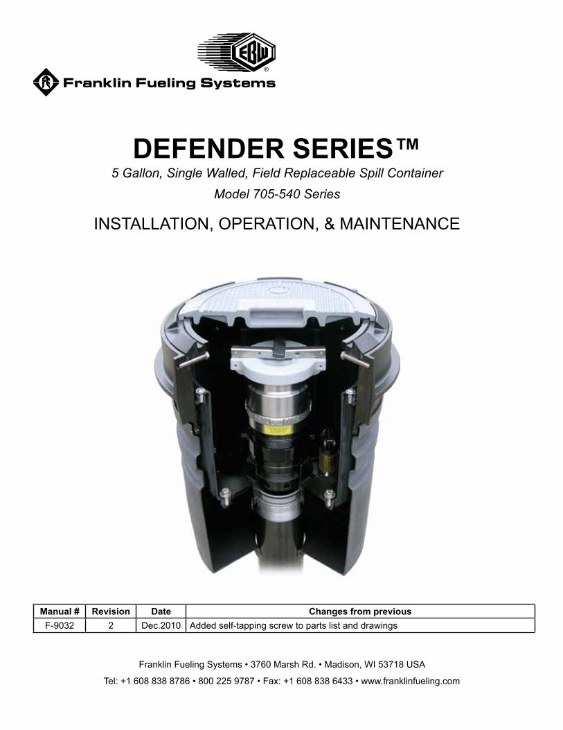
DEFENDER SERIES™5 Gallon, Single Walled, Field Replaceable Spill Container
Model 705-540 Series
INSTALLATION, OPERATION, & MAINTENANCE
Franklin Fueling Systems • 3760 Marsh Rd. • Madison, WI 53718 USA
Tel: +1 608 838 8786 • 800 225 9787 • Fax: +1 608 838 6433 • www.franklinfueling.com
Manual # Revision Date Changes from previousF-9032 2 Dec.2010 Added self-tapping screw to parts list and drawings
2
ContentsComponent and Subassembly Illustrations .........3Replacement Parts .............................................. 3-4Preparation ..............................................................5
New Site / Retrofit Site ........................................5
Overview Diagram ...................................................6Installation ........................................................... 7-8Integrity Testing ......................................................8
Spill Container Subassembly Replacement .........9
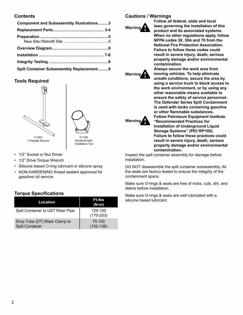
Tools Required
T-7001T-Handle Wrench
T-7106 Double-Ended Installation Tool
• 1/2” Socket or Nut Driver• 1/2” Drive Torque Wrench• Silicone based O-ring lubricant or silicone spray• NON-HARDENING thread sealant approved for
gasoline / oil service
Torque Specifications
Location Ft-lbs (N-m)
Spill Container to UST Riser Pipe 125-150 (170-203)
Drop Tube (DT) Riser Clamp to Spill Container
75-100 (102-136)
Cautions / WarningsFollow all federal, state and local laws governing the installation of this product and its associated systems. When no other regulations apply, follow NFPA codes 30, 30A and 70 from the National Fire Protection Association. Failure to follow these codes could result in severe injury, death, serious property damage and/or environmental contamination. Always secure the work area from moving vehicles. To help eliminate unsafe conditions, secure the area by using a service truck to block access to the work environment, or by using any other reasonable means available to ensure the safety of service personnel.The Defender Series Spill Containment is used with tanks containing gasoline or other flammable substances. Follow Petroleum Equipment Institute “Recommended Practices for Installation of Underground Liquid Storage Systems” (PEI / RP100). Failure to follow these practices could result in severe injury, death, serious property damage and/or environmental contamination.
Inspect the spill container assembly for damage before installation.
DO NOT disassemble the spill container subassembly. All the seals are factory tested to ensure the integrity of the containment space.
Make sure O-rings & seals are free of nicks, cuts, dirt, and debris before installation.
Make sure O-rings & seals are well lubricated with a silicone based lubricant.
Warning
Warning
Warning
3
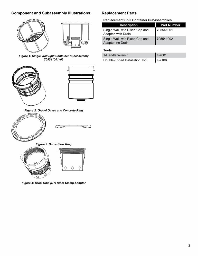
Component and Subassembly Illustrations
Figure 1: Single Wall Spill Container Subassembly 705541001 / 02
Figure 2: Gravel Guard and Concrete Ring
Figure 3: Snow Plow Ring
Figure 4: Drop Tube (DT) Riser Clamp Adapter
Replacement Parts
Replacement Spill Container SubassembliesDescription Part Number
Single Wall, w/o Riser, Cap and Adapter, with Drain
705541001
Single Wall, w/o Riser, Cap and Adapter, no Drain
705541002
ToolsT-Handle Wrench T-7001Double-Ended Installation Tool T-7106
4
1
2
5
6
7
3
4
8
10
9
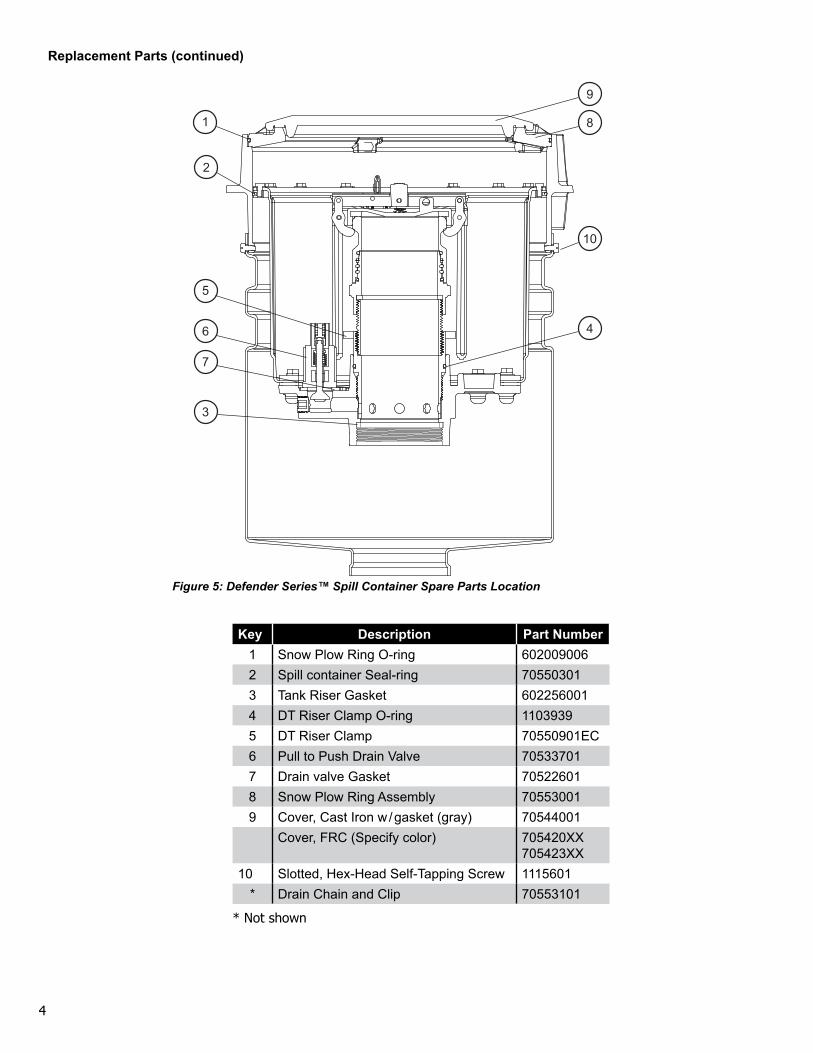
Key Description Part Number1 Snow Plow Ring O-ring 6020090062 Spill container Seal-ring 705503013 Tank Riser Gasket 6022560014 DT Riser Clamp O-ring 11039395 DT Riser Clamp 70550901EC6 Pull to Push Drain Valve 705337017 Drain valve Gasket 705226018 Snow Plow Ring Assembly 705530019 Cover, Cast Iron w / gasket (gray) 70544001
Cover, FRC (Specify color) 705420XX 705423XX
10 Slotted, Hex-Head Self-Tapping Screw 1115601* Drain Chain and Clip 70553101
* Not shown
Replacement Parts (continued)
Figure 5: Defender Series™ Spill Container Spare Parts Location
5
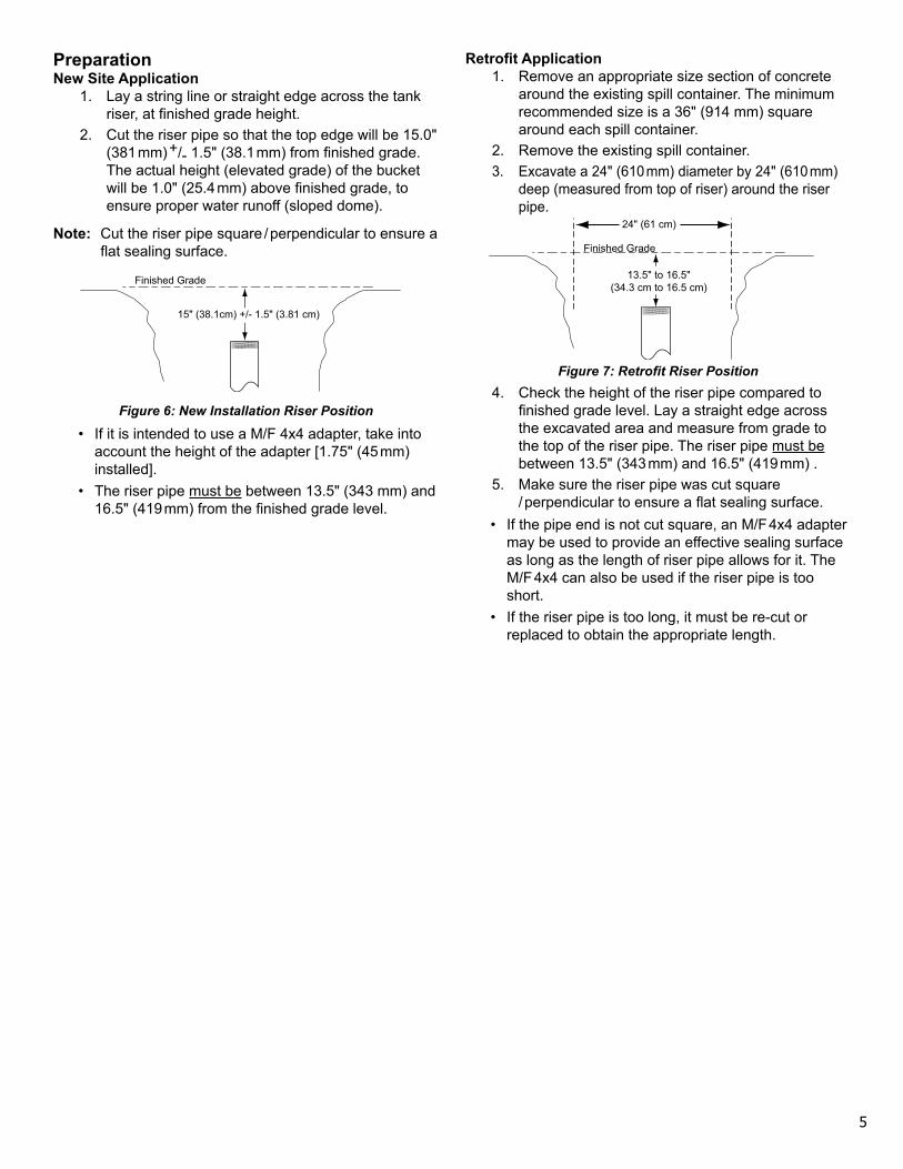
PreparationNew Site Application
1. Lay a string line or straight edge across the tank riser, at finished grade height.
2. Cut the riser pipe so that the top edge will be 15.0" (381 mm) +/- 1.5" (38.1 mm) from finished grade. The actual height (elevated grade) of the bucket will be 1.0" (25.4 mm) above finished grade, to ensure proper water runoff (sloped dome).
Note: Cut the riser pipe square / perpendicular to ensure a flat sealing surface.
Finished Grade
15" (38.1cm) +/- 1.5" (3.81 cm)
Figure 6: New Installation Riser Position
• If it is intended to use a M/F 4x4 adapter, take into account the height of the adapter [1.75" (45 mm) installed].
• The riser pipe must be between 13.5" (343 mm) and 16.5" (419 mm) from the finished grade level.
Retrofit Application1. Remove an appropriate size section of concrete
around the existing spill container. The minimum recommended size is a 36" (914 mm) square around each spill container.
2. Remove the existing spill container.3. Excavate a 24" (610 mm) diameter by 24" (610 mm)
deep (measured from top of riser) around the riser pipe.
Finished Grade
13.5" to 16.5"(34.3 cm to 16.5 cm)
24" (61 cm)
Figure 7: Retrofit Riser Position4. Check the height of the riser pipe compared to
finished grade level. Lay a straight edge across the excavated area and measure from grade to the top of the riser pipe. The riser pipe must be between 13.5" (343 mm) and 16.5" (419 mm) .
5. Make sure the riser pipe was cut square / perpendicular to ensure a flat sealing surface.
• If the pipe end is not cut square, an M/F 4x4 adapter may be used to provide an effective sealing surface as long as the length of riser pipe allows for it. The M/F 4x4 can also be used if the riser pipe is too short.
• If the riser pipe is too long, it must be re-cut or replaced to obtain the appropriate length.
6
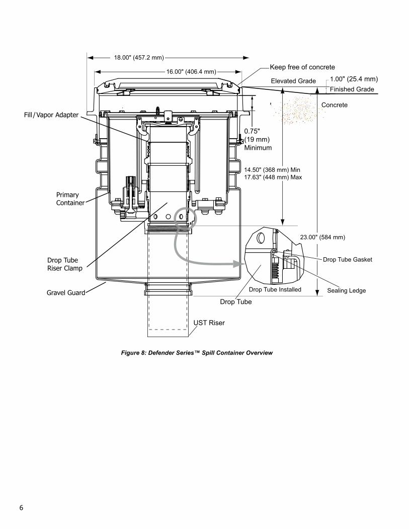
1.00" (25.4 mm)Finished Grade
Elevated Grade
Concrete
Keep free of concrete
0.75" (19 mm) Minimum
Drop Tube
UST Riser
14.50" (368 mm) Min17.63" (448 mm) Max
23.00" (584 mm)
16.00" (406.4 mm)
18.00" (457.2 mm)
Drop Tube Installed
Drop Tube Gasket
Sealing Ledge
Figure 8: Defender Series™ Spill Container Overview
Drop Tube Riser Clamp
Fill / Vapor Adapter
Primary Container
Gravel Guard
7
Installation1. Remove the DT Riser Clamp Adapter from the
Defender Series™ Spill container assembly.2. Use the round end of the T-7106 double ended
tightening tool and the T-7001 T-Handle. The slots on the tool will engage with the lugs on the DT Riser Clamp Adapter.
3. Apply a NON-HARDENING thread sealant to the tank riser.
4. Install the Defender Series™ Spill container assembly to the tank riser and tighten using square end of the T-7106 double-ended installation tool and the T-7001 T-Handle. Torque to 125-150 ft-lbs (170-203 N-m) using a 1/2" drive torque wrench.
Note: If local codes or regulations require a tightness test using a leak detecting solution at the tank riser / spill bucket joint:
a. Make sure the snowplow ring is installed in the concrete ring before proceeding.
b. Remove the (4) slotted hex-head self-tapping screws from the gravel guard.
c. Slide the gravel guard down to access the joint between the tank riser and the spill bucket.
d. Perform a tightness test.e. Reinstall the gravel guard and attach it with the
(4) self-tapping screws.5. Adjust the height of the top edge to the ELEVATED
grade, which should be approximately 1” (25.4 mm) above finished grade level (1” (25.4 mm) of rain runoff dome).
6. Adjust the height of the top edge to the ELEVATED grade, which should be approximately 1" (25.4 mm) above finished grade level (1" (25.4 mm) of rain runoff dome).
7. If needed, support the gravel guard / concrete ring with backfill.• If backfill is not available, temporarily support the
concrete ring with 2x4s underneath the outer edge.8. Install the drop tube through the spill container to
allow the gasket to seat on the sealing ledge.• *Retrofit Installation Only* – Double check to
see that the existing drop tube is cut to the appropriate length.
9. If the unit was ordered with the riser, cap, and fill / vapor adapter – they should all be pre-assembled to the DT Riser Clamp Adapter – SKIP TO STEP 5.
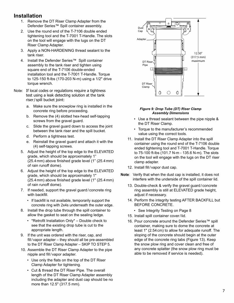
10. Assemble the DT Riser Clamp Adapter to the pipe nipple and fill / vapor adapter.• Use only the flats on the top of the DT Riser
Clamp Adapter for tightening.• Cut & thread the DT Riser Pipe. The overall
length of the DT Riser Clamp Adapter assembly including the adapter and dust cap should be no more than 12.5" (317.5 mm).
12.50"(317.5 mm)maximumDT Riser
Pipe
Dust Cap
Adapter
DT Riser Clamp
Figure 9: Drop Tube (DT) Riser Clamp Assembly Dimensions
• Use a thread sealant between the pipe nipple & the DT Riser Clamp.
• Torque to the manufacturer’s recommended value using the correct tools.
11. Install the DT Riser Clamp Adapter into the spill container using the round end of the T-7106 double ended tightening tool and T-7001 T-Handle. Torque to 75-100 ft-lbs (101.7 N-m - 135.6 N-m). The slots on the tool will engage with the lugs on the DT riser clamp adapter.
12. Install fill / vapor dust cap.
Note: Verify that when the dust cap is installed, it does not interfere with the underside of the spill container lid.
13. Double-check & verify the gravel guard / concrete ring assembly is still at ELEVATED grade height, adjust if necessary.
14. Perform the integrity testing AFTER BACKFILL but BEFORE CONCRETE.• See Integrity Testing on Page 8
15. Install spill container cover / lid.16. Pour concrete around the Defender Series™ spill
container, making sure to dome the concrete at least 1" (2.54 cm) to allow for adequate runoff. The sloping of the concrete should begin at the outer edge of the concrete ring tabs (Figure 13). Keep the snow plow ring and cover clean and free of any concrete splatter (the snow plow ring must be able to be removed if service is needed).
8
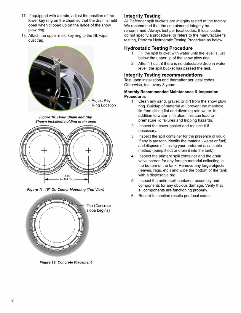
17. If equipped with a drain, adjust the position of the lower key ring on the chain so that the drain is held open when clipped up on the ledge of the snow plow ring.
18. Attach the upper most key ring to the fill / vapor dust cap.
Figure 10: Drain Chain and Clip Shown installed, holding drain open
16.00"(406.4 mm)
Figure 11: 16" On-Center Mounting (Top View)
Figure 12: Concrete Placement
Integrity TestingAll Defender spill buckets are integrity tested at the factory. We recommend that the containment integrity be re-confirmed. Always test per local codes. If local codes do not specify a procedure, or refers to the manufacturer’s testing, Perform Hydrostatic Testing Procedure as below.
Hydrostatic Testing Procedure1. Fill the spill bucket with water until the level is just
below the upper lip of the snow plow ring.2. After 1 hour, if there is no detectable drop in water
level, the spill bucket has passed the test.
Integrity Testing recommendationsTest upon installation and thereafter per local codes. Otherwise, test every 3 years
Monthly Recommended Maintenance & Inspection Procedures
1. Clean any sand, gravel, or dirt from the snow plow ring. Buildup of material will prevent the manhole lid from sitting flat and diverting rain water. In addition to water infiltration, this can lead to premature lid failures and tripping hazards.
2. Inspect the cover gasket and replace it if necessary.
3. Inspect the spill container for the presence of liquid. If any is present, identify the material (water or fuel) and dispose of it using your preferred acceptable method (pump it out or drain it into the tank).
4. Inspect the primary spill container and the drain valve screen for any foreign material collecting in the bottom of the tank. Remove any large objects (leaves, rags, etc.) and wipe the bottom of the tank with a disposable rag.
5. Inspect the entire spill container assembly and components for any obvious damage. Verify that all components are functioning properly.
6. Record Inspection results per local codes.
Adjust Key Ring Location
Tab (Concrete slope begins)
9
Spill Container Subassembly ReplacementRemoval
1. Remove cover.2. Remove the snow plow ring.
• Unthread the snow plow ring bolts using a 1/2" (13 mm)socket or nutdriver, until the heads of the bolts extend past the I.D. approximately 1/2" (13 mm).
• Pull up on the snow plow ring firmly to break the seal between the O-ring and the concrete ring.
3. Remove the dust cap.4. Using the round end of the T-7106 double-ended
installation tool and T-7001 T-Handle, remove the DT riser clamp adapter.
5. Remove the drop tube assembly.6. Using the square end of the T-7106 double-ended
installation tool and the T-7001 T-Handle, unthread the spill container assembly.
7. Pull up firmly and evenly on the spill container to remove the spill container from the concrete ring / gravel guard.
Installation1. Clean the I.D. of the concrete ring (sealing
surface) thoroughly and re-lubricate with a silicone based O-ring lubricant or spray.
2. Apply a NON-HARDENING thread sealant to the tank riser.
3. Lubricate the seal on the outside of the spill container with a silicone based O-ring lubricant or spray.
4. Evenly push down on the spill container subassembly to seat the seal-ring, & slide it down to where the bucket meets the tank riser.
5. Thread on the spill container subassembly to the tank riser using square end of the T-7106 double-ended installation tool and The T-7001 T-Handle. Torque to 125-150 ft-lbs (169.5 - 203.4 N-m) using a 1/2" (13 mm) drive torque wrench.
6. Re-install the drop tube assembly.• Check the drop tube gasket and replace if
necessary.7. Re-install the DT Riser Clamp Adapter into the
spill container using the round end of the T-7106 double ended tightening tool and T-7001 T-Handle. The slots on the tool will engage with the lugs on the DT riser clamp adapter. Torque to 75-100 ft-lbs (102-136 N-m).
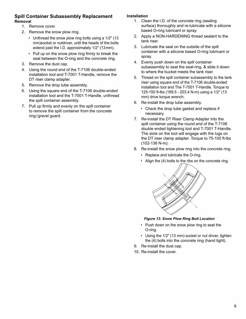
8. Re-install the snow plow ring into the concrete ring.• Replace and lubricate the O-ring.• Align the (4) bolts to the ribs on the concrete ring.
Figure 13: Snow Plow Ring Bolt Location
• Push down on the snow plow ring to seat the O-ring.
• Using the 1/2" (13 mm) socket or nut driver, tighten the (4) bolts into the concrete ring (hand tight).
9. Re-install the dust cap.10. Re-install the cover.

10
Page intentionally blank

11
Page intentionally blank

©2010 FFS F-9032 Rev 2