Defect Improvement of Extrusion Dies Using Combination · PDF fileDEFECT IMPROVEMENT OF...
10
DEFECT IMPROVEMENT OF EXTRUSION DIES USING COMBINATION OF FEM STRESS ANALYSIS WITH THE TAGUCHI METHOD Kao-Hua Chang 1 , Ching-Wei Shih 1 and Gow-Yi Tzou 2 1 Department of Mold and Die Engineering, National Kaohsiung University of Applied Sciences, Kaohsiung, Taiwan, R.O.C. 2 Department of Mechanical and Automation Engineering, Chung Chou University of Science and Technology, Changhua, Taiwan, R.O.C. E-mail: [email protected] ICETI-2014 W1035_SCI No. 15-CSME-55, E.I.C. Accession 3830 ABSTRACT This study aims at analyzing the influence of the maximum principal stress on Tungsten Carbide Steel die core in an extrusion die which caused the crack of die core, and then adjusts the dies assembly method in order to improve the service life of die. In this study, we combine FEM simulation software with the Taguchi Method L 9 (3 4 ) to choose the cobalt content for die core materials, and the quantity of shrink fit while assembling the die core and die case as the reference parameters. When carrying out the simulation process, we compared the changes of the maximum principal stress of the die core caused by the plastic deformation of die materials to achieve the minimum expected value as the goal for the most optimal die combination. Then, the results obtained are to make dies in trial and mass-production practically; as a result, the die life is improved from the original 1000 to 150,000 pcs, which is more than 150 times better than before. Keywords: tungsten carbide steel; maximum principal stress; shrink fit; Taguchi method. ÉTUDE POURL’AMÉLIORATION DES DÉFAUTS DES MATRICES D’EXTRUSION UTILISANT LA MÉTHODE DES ÉLÉMENTS FINIS (FEM) AVEC LA MÉTHODOLOGIE TAGUCHI RÉSUMÉ Cette étude a pour but d’analyser l’influence des contraintes principales maximales sur un noyau de matrice en carbure de tungstène dans une matrice d’extrusion causant la fissure du noyau de la matrice, et par la suite, ajuster la méthode d’assemblage des matrices afin d’améliorer la durée de service de la matrice. Dans cette étude, la combinaison du logiciel de simulation FEM avec la méthodologie Taguchi est de choisir l’alliage de cobalt pour la matrice d’extrusion et l’ajustement fretté pendant l’assemblage du noyau et du corps de la matrice. Au cours du processus de simulation, on fait la comparaison des changements des contraintes principales maximales de la matrice d’extrusion, causées par la déformation du plastique du matériel de la matrice, comme l’objectif à atteindre pour la combinaison optimale. Les résultats obtenus permettent de mettre la matrice à l’essai, et éventuellement d’en faire une production de masse. Il est prévu que la durée de vie de la matrice s’améliore de 1000 ps à 150.000 ps, ce qui représente 150 fois plus qu’avant. Mots-clés : carbure de tungstène; contrainte principale maximale; ajustement fretté; méthodologie Taguchi. Transactions of the Canadian Society for Mechanical Engineering, Vol. 39, No. 3, 2015 729
Transcript of Defect Improvement of Extrusion Dies Using Combination · PDF fileDEFECT IMPROVEMENT OF...

DEFECT IMPROVEMENT OF EXTRUSION DIES USING COMBINATION OF FEM STRESSANALYSIS WITH THE TAGUCHI METHOD
Kao-Hua Chang1, Ching-Wei Shih1 and Gow-Yi Tzou21Department of Mold and Die Engineering, National Kaohsiung University of Applied Sciences, Kaohsiung, Taiwan,
R.O.C.2Department of Mechanical and Automation Engineering, Chung Chou University of Science and Technology,
Changhua, Taiwan, R.O.C.E-mail: [email protected]
ICETI-2014 W1035_SCINo. 15-CSME-55, E.I.C. Accession 3830
ABSTRACTThis study aims at analyzing the influence of the maximum principal stress on Tungsten Carbide Steel diecore in an extrusion die which caused the crack of die core, and then adjusts the dies assembly methodin order to improve the service life of die. In this study, we combine FEM simulation software with theTaguchi Method L9(34) to choose the cobalt content for die core materials, and the quantity of shrink fitwhile assembling the die core and die case as the reference parameters. When carrying out the simulationprocess, we compared the changes of the maximum principal stress of the die core caused by the plasticdeformation of die materials to achieve the minimum expected value as the goal for the most optimal diecombination. Then, the results obtained are to make dies in trial and mass-production practically; as aresult, the die life is improved from the original 1000 to 150,000 pcs, which is more than 150 times betterthan before.
Keywords: tungsten carbide steel; maximum principal stress; shrink fit; Taguchi method.
ÉTUDE POUR L’AMÉLIORATION DES DÉFAUTS DES MATRICESD’EXTRUSION UTILISANT LA MÉTHODE DES ÉLÉMENTS FINIS (FEM)
AVEC LA MÉTHODOLOGIE TAGUCHI
RÉSUMÉCette étude a pour but d’analyser l’influence des contraintes principales maximales sur un noyau de matriceen carbure de tungstène dans une matrice d’extrusion causant la fissure du noyau de la matrice, et par la suite,ajuster la méthode d’assemblage des matrices afin d’améliorer la durée de service de la matrice. Dans cetteétude, la combinaison du logiciel de simulation FEM avec la méthodologie Taguchi est de choisir l’alliagede cobalt pour la matrice d’extrusion et l’ajustement fretté pendant l’assemblage du noyau et du corps dela matrice. Au cours du processus de simulation, on fait la comparaison des changements des contraintesprincipales maximales de la matrice d’extrusion, causées par la déformation du plastique du matériel de lamatrice, comme l’objectif à atteindre pour la combinaison optimale. Les résultats obtenus permettent demettre la matrice à l’essai, et éventuellement d’en faire une production de masse. Il est prévu que la duréede vie de la matrice s’améliore de 1000 ps à 150.000 ps, ce qui représente 150 fois plus qu’avant.
Mots-clés : carbure de tungstène; contrainte principale maximale; ajustement fretté; méthodologie Taguchi.
Transactions of the Canadian Society for Mechanical Engineering, Vol. 39, No. 3, 2015 729
1. INTRODUCTION
In the forging process, the die failure is usually caused by die wears, fatigue failure, plastic deformation,etc., and 70% failure in hot forging came from wearing; moreover, in cold forging process, the die failurewas almost caused by the endurance failure. This study can be considered as an actual example in the coldforging process, thus it mainly explores isotropic fatigue failure. Its failure mechanism almost results fromthe mechanical load on the die, and the effective stress acting on some local areas exceeds the yield strengthof tools and materials that caused stress concentration and formed a plastic deformation area; such a stressconcentration phenomenon could easily cause dies failure.
In an ideal situation, the effective stress die bore should be less than the yield strength; however, sincethe forging frequency, the dies would bear and release load continuously and reciprocally, which wouldcause failure in die at the end [1, 2]. Therefore, this component of stress–maximum principal stress iscommonly used as an indicator of predicting fatigue failure. Along with the macroscopic scale, fracturesurface (crack) is often perpendicular to the direction of the maximum principal stress. Walters et al. [3]think that in the cold forging process, the forging pressure is usually very high, thus its die will yield alongwith higher stress. As a result, the cold forging die must have a high-strength characteristic, however, it willshow some brittle characteristics meanwhile, thus the fragility caused by tensile stress will be much morethan the compressive stress. At the position of the failed die core, it always discovers that the maximumprincipal stress would be the stretching situation, and most carbide alloy materials dies are subjected to themaximum principal stress; in fact, there would be smaller tensile stress, around 200 MPa ∼ 350 MPa, but itwould have higher compressive stress around 2800 ∼ 3500 MPa at such position normally. Vazquez et al.[4] also think the horizontal crack of die that would be caused by the maximum principal stress of stretchingyielded at the round turn of inside cavity while forming; in addition, the maximum principal stress exceedsthe die’s yielding strength and causes initial crack and then gradually stretches out. In order to solve thisproblem, it has to make use of the compression assembly for the die case to die core to produce compressivepre-stress to make up or reduce the tensile stress occurring from forming, or even horizontally cut the diecore into upper and bottom parts at the round turn of inside the cavity. As a result, it would make die core tocause positive maximum principal stress to compensate in the forging process, or even negative compressivestress would be left as well. Liu et al. [5] apply Deform software to analyze the forging process for nuts oftruck tires which discover the stretching axial stress yielded on the punch while forming, thus it results incrack of punch while exiting from die. Dehghani et al. [6] use FEM to analyze the stress occurring fromthe die of bolt forging; there are many methods to increase the die’s service life, such as properly cut atthe position where the die core bearing the stress concentration to reduce the stress value, and use stressring to generate the compressive pre-stress on the die core, which could use to make up the tensile stressoccurring from the forging process, and increase die core’s service life. Since the cold forging productsneed higher dimensional accuracy and strongly depend on elastic characteristics of die materials, Hur et al.[7] therefore adopt the sintered tungsten steel material, in which its high stiffness is able to reduce elasticdeformation in the forging process, but the tungsten steel material is hard to resist tensile stress occurringfrom forging process. Therefore, the tungsten steel die applies the stress ring and shrink fit to reduce itselastic deformation in the cold forging process, as well as reduce the influential level of the die’s elasticdeformation on dimensional accuracy for products. Therefore, Yokoyama et al., Goh et al., and Kim et al.[8–10] also use the shrink fit of stress ring and FEM to understand how the stress distribution on the diewould influence the changes in the die’s vertical and circumferential stresses yielded while forging whichcould make the die to obtain the maximum service life in the forging process. Biba et al. [11] use the QFormsimulation software and the point-tracking mode to investigate the growing trend of crack value which isobtained from the forming in each stage, and then make improvement in the part or stage exceeding thecritical limit value. Walters et al. and Li et al. [12, 13] analyze the shrink fit that initially changed between
730 Transactions of the Canadian Society for Mechanical Engineering, Vol. 39, No. 3, 2015

Fig. 1. Illustration of forward extrusion.
die case and core for improving the crack of die core, and they discover that within a smaller shrink fit, thedie core’s effective stress is lower than the yielding strength, but it couldn’t reduce the maximum principalstress of stretching. However, within a higher shrink fit, the die core’s effective stress is already higher thanmaterial’s yielding strength. Therefore, under certain situations, it could not reach the reduction of tensilestress with only changing the shrink fit between the die case and the core. Thus, it needs to be aided byincreasing stress ring to achieve the requirement.
In this study, it applies the FEM simulation software, and chooses the cobalt content of die core mate-rials, the shrink fit of assembling die core and die case, the usage of stress ring and various designs withdifferent assembly angles altogether as the reference parameters. When carrying out simulation along withthe Taguchi Method L9(34), we compare the changes of die in the plastic deformation process, which causesthe die core to bear the maximum principal stress, adopt the optimization of the maximum principal stressto be minimal expected value as the target, choose the most optimal die combination, and then carry outthe trial for practical application with such optimal combination, and conduct the relevant comparison withconfirming its feasibility.
2. PROBLEM STATEMENT
This study adopts one of extrusion molding stages in the multi-stage cold forging process as the researchobject, when the billet enters a die with diameter 15.46 mm; then reduces its diameter to 12.88 mm by theforward extrusion method, and the relative position between billet and die is shown in Fig. 1. Its percentageof area reduction is about 30%. In terms of die, the die core is made of the tungsten steel containing 24%Co, the die case material is made of the hot work tool steel SKD61, and the shrink fit is 0.4% with using thecylinder compression fit.
For the hypothesis of this study, it designs a process with 30% percentage of area reduction and 7.5◦
semi-die angle to carry out the forward extrusion. In general, it could be considered as a convenient process;however, the horizontal crack yielded from the actual forging die and its service life was very short with1000 pcs only. The horizontal crack in Fig. 1 appeared along the direction of view A, and such photo isshown in Fig. 2, it shows that the die’s crack point at the inlet of semi-die angle was at B in Fig. 1, and it isthe starting point of billet to start conducting the extrusion process.
In general, the tungsten steel die has 2 types of crack. One is the vertical crack in which its crack linewill be developed along the axial line, and it is because the powder-sintered tungsten steel could not bear
Transactions of the Canadian Society for Mechanical Engineering, Vol. 39, No. 3, 2015 731
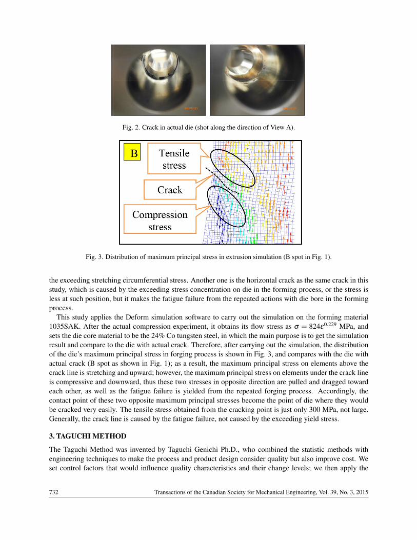
Fig. 2. Crack in actual die (shot along the direction of View A).
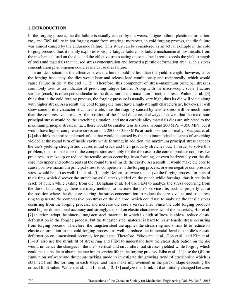
Fig. 3. Distribution of maximum principal stress in extrusion simulation (B spot in Fig. 1).
the exceeding stretching circumferential stress. Another one is the horizontal crack as the same crack in thisstudy, which is caused by the exceeding stress concentration on die in the forming process, or the stress isless at such position, but it makes the fatigue failure from the repeated actions with die bore in the formingprocess.
This study applies the Deform simulation software to carry out the simulation on the forming material1035SAK. After the actual compression experiment, it obtains its flow stress as σ = 824ε0.229 MPa, andsets the die core material to be the 24% Co tungsten steel, in which the main purpose is to get the simulationresult and compare to the die with actual crack. Therefore, after carrying out the simulation, the distributionof the die’s maximum principal stress in forging process is shown in Fig. 3, and compares with the die withactual crack (B spot as shown in Fig. 1); as a result, the maximum principal stress on elements above thecrack line is stretching and upward; however, the maximum principal stress on elements under the crack lineis compressive and downward, thus these two stresses in opposite direction are pulled and dragged towardeach other, as well as the fatigue failure is yielded from the repeated forging process. Accordingly, thecontact point of these two opposite maximum principal stresses become the point of die where they wouldbe cracked very easily. The tensile stress obtained from the cracking point is just only 300 MPa, not large.Generally, the crack line is caused by the fatigue failure, not caused by the exceeding yield stress.
3. TAGUCHI METHOD
The Taguchi Method was invented by Taguchi Genichi Ph.D., who combined the statistic methods withengineering techniques to make the process and product design consider quality but also improve cost. Weset control factors that would influence quality characteristics and their change levels; we then apply the
732 Transactions of the Canadian Society for Mechanical Engineering, Vol. 39, No. 3, 2015

Fig. 4. Control factors setting diagram for the Taguchi Method L9(34).
statistic technique to design the Orthogonal Array and simplify the data analysis to make its results to bemore reliable [14].
According to previous experiences, if it intends to increase the die’s capability of bearing stress, theneach method and data of die assembly are adjusted that will be helpful to the service life of the die. Thefollowing describe the parameter of control factors and the division of change levels as shown in Fig. 4.
A: The content of adhesive [cobalt (Co)]: For the choice of die core materials, the content of adhesive[cobalt (Co)] that was used before sintering for the chose tungsten steel materials will influence the hardnessof the sintered materials, and further influence its wear and impact resistance; that is, materials withhigher cobalt content will have less hardness; and higher impact resistance will reduce the wear resistance.Tungsten steel material used for the die core is limited by specification prescribed by manufacturers, wheremore or less Co was the standard of differentiation, that is, a total of four types including 10, 15, 19 and24% under general situation; the latter three of them were used in this study.
B: Compression fit of die: Because this die is composed of three sections, it will have two contact surfacesthat need to choose the compression fit methods: the first contact surface is between die core and innerstress ring, another one is between inner stress ring and outer die case. Since the first contact surface isincluding die core, and it also is the core for the entire forming process, thus the fitting method and angleselection of the first contact surface include 0◦ cylinder fit and 2◦ and 4◦ incline fit; the second contactsurface can only be used with 0◦ cylinder fit then. Practically speaking, inclined fit would be more stable,but the quantity of angle would be the most optimal condition, especially when it still needs to be fitted withother factors, and there will various changes in such result.
C: Shrink fit for inner stress ring: Based on previous experiences, it will choose three types of shrink fit forinner stress ring: 0.4, 0.6 and 0.8%, because shrink fit less than 0.4% is only able to yield small compressedstress, with smaller effects to improve life of use of die. On the contrary, shrink fit more than 0.8% is ableto yield larger compressed stress, leading to crack of die core generated in the assembly. Its main purpose isto use the shrink fit to make die to pre-set the compressive stress, while assembling die, to resist and reducethe tensile stress that is yielded from the forming process, thus increase the die’s service life.
Transactions of the Canadian Society for Mechanical Engineering, Vol. 39, No. 3, 2015 733

Table 1. Control factors and levels for the Taguchi Method L9(34).Level 1 Level 2 Level 3
A Material(WC-Co) 15% Co 19% Co 24% CoB Assembly degree 0◦ 2◦ 4◦
C Inner shrink fit 0.4% 0.6% 0.8%D Outer shrink fit 0.4% 0.5% 0.6%
Table 2. L9(34) parameters layout and simulation result.EXP A B C D Result (σp)max (MPa)
1 1 1 1 1 308.562 1 2 2 2 218.153 1 3 3 3 301.244 2 1 2 3 315.815 2 2 3 1 74.916 2 3 1 2 348.227 3 1 3 2 120.818 3 2 1 3 323.259 3 3 2 1 205.90
D: The shrink fit of outer die case: The shrink fit between inner and outer rings is set to be 0.4, 0.5 and0.6%, which is aimed at supplementing deficiency between inner ring and die core; the selection of shrinkfit of outer ring is usually smaller than that of inner ring. As larger shrink fit of outer ring will intervenewith that of inner ring, it would reduce effects as expected in turn.
We listed four control factors in Table 1 with three levels respectively. Applying the Taguchi Method tochoose the L9(34) statistic methods as shown in Table 2, we obtain the parameter setting for nine experi-ments. It adopts the smaller-the-better characteristics; that is, the smaller maximum principal stress on thedie in the forming process will have better result.
4. SIMULATION ANALYSIS
This study uses simulation software DEFORM-3D [15], wherein the simulation process is divided into twoparts; first, it simulates the billet’s being squeezed in the die; the billet is set as a plastic object configuredwith node and element and die is set as a rigid body; constant shear friction factor (m) is used betweenthem. After simulation, billet is squeezed under its own condition of flow stress, its plastic material has beendeformed, and information of strain is retained in the element and node. The second part is to simulate thedie with stress analysis; the die contains die core, inner ring and outer ring; these three objects are set aselastic body, configuration node and element; then the materials used, shrink fit among them and constantshear friction factor (m) are set. After that, we insert the force of every node which the billet acquired duringthe first part of squeezing into the node of die core. These forces are delivered among nodes of die core,inner ring and outer ring until the balance is maintained.
In the simulation results, the die is fixed at the same position, thus in actual extrusion such die’s crackpositions are shown in Fig. 5, we circularly and averagely collect the maximum principal stress from 20points to make comparison.
Figure 6 shows the entire quantity of maximum principal stress distribution for each element in the simu-lation results. Thus, in Fig. 6, it discovers that almost every experiment’s line shape is very similar to eachother; in addition, among these nine experiments, Exp5 shows the lowest value of maximum principal stress,
734 Transactions of the Canadian Society for Mechanical Engineering, Vol. 39, No. 3, 2015

Fig. 5. Schematic diagram of crack position of maximum principal stress.
Fig. 6. Sets of maximum principal stress results for L9(34).
and Exp6 has the highest data of principal stress. Then, we take the highest value of principal stress fromeach experiment, and place in Table 2 for further analysis. After computing the maximum principal stressin Table 2, the parameters of quality characteristics obtained within various levels and their influences onthese nine simulation results are shown in Table 3 and Fig. 7.
5. RESULTS AND DISCUSSIONS
Table 3 is quality characteristics factor response table, it shows that among these four parameters of qualitycharacteristics, the changes in three levels of shrink fit for inner ring in Item C have the biggest influenceon all experiment results; that is, since the shrink fit changes from 0.4, 0.6 and 0.8% for inner ring, theexperiment obtained the results of the maximum principal stress to be changed from 326.68 to 165.66 MPa,the difference would be up to 161.02 MPa. Figure 7 is quality characteristics factor response diagram, itshows a bigger inner ring shrink fit in Item C, its maximum principal stress is smaller then, thus for the innerring shrink fit, its yield of maximum principal stress would be an inverse ratio to the shrink fit. This meansthat the inner ring shrink fit would choose the biggest value from 0.4, 0.6 and 0.8% to make the die core toobtain more compressive pre-stress before forming, so as to offset stress yielded from the forming processand also to make smaller yield of the maximum principal stress finally.
Next in Item D, the outer ring shrink fit’s influential level is ranked in 2nd place. Changes of 0.4, 0.5 and0.6% make the maximum principal stress of such experiment to be changed from 196.46 to 313.44 MPa, witha significant difference of 116.98 MPa. In addition, changes in Item D’s three levels of outer ring shrink fit
Transactions of the Canadian Society for Mechanical Engineering, Vol. 39, No. 3, 2015 735

Table 3. Quality characteristics factor response table.A B C D
Level 1 275.99 248.40 326.68 196.46Level 2 246.32 205.44 246.63 229.07Level 3 216.66 285.13 165.66 313.44Range 59.33 79.69 161.02 116.98Rank 4 3 1 2
Fig. 7. Quality characteristics factor response diagram.
are opposite to Item C, in which a bigger maximum principal stress would be obtained at the biggest shrinkfit 0.6%, and the smallest shrink fit 0.4% would then be got smaller than the maximum principal stress;therefore, the quantity of outer ring shrink fit is directly proportional to the yield of maximum principalstress; accordingly, the quantity of outer ring shrink fit is proper and better but bigger. Table 2 shows thatthe outer ring shrink fit is D3(0.6%), no matter how combining other three items: A, B and C, its maximumprincipal stress would be greater than 300 MPa, and significantly close to each other. When choosingD1(0.4%) and D2(0.5%), with different combinations of A, B and C, the obtained quantities of maximumprincipal stress would be very different from each other. Especially, changes in maximum principal stressare discovered that are significantly influenced by Item C which shows a similar tendency. Therefore, inthe case of bigger outer ring shrink fit, it apparently would offset the compressive pre-stress effect that wasyielded from the inner ring shrink fit.
Item B shows the assembly methods for a die, in Fig. 7. It shows a turning point, in which a proper 2◦
inclined assembly method is better than cylinder or more inclination, such as 4◦. However, it has less andless influence on the experiment results, and thus ranks in the 3rd place.
For the last choice of die core materials, Table 3 and Fig. 7 show that it has the least importance and thedifference between the biggest and smallest is only 59.33 MPa. Thus, when choosing materials with highercobalt contents, such as A3 (24% Co), as the die core materials, it may yield less maximum principal stress;however, with lower cobalt contents, such as Al (15% Co), it may yield bigger maximum principal stress.Even the difference is not significant, it still can determine that, within conditions stated in this study, lesshardness of die core materials will have higher cobalt content and obtain smaller maximum principal stress.Thus, the hardness of die core materials is obviously not different in the maximum principal stress that thedie core bore in the cold forging process. However, the tungsten steel with higher cobalt content will haveless hardness, as well as a small Young’s Modulus, thus it has bigger elastic deformation, which wouldrender the dimension precision of forged products difficult to control in the extrusion process, and then losethe die’s service life.
We recombine the optimal combination, A3, B2, C3 and D1, by using the Taguchi Method L9(34) Or-thogonal Array, and apply the simulation software Deform 3D to carry out the simulation, and then compare
736 Transactions of the Canadian Society for Mechanical Engineering, Vol. 39, No. 3, 2015
Table 4. Simulation result comparison before and after modifying quality characteristics factors.A B C D Result (σp)max MPa
Original EXP A3 B1 C1 D1 259.10Modified EXP A3 B2 C3 D1 60.23
Fig. 8. Maximum principal stress distribution of original die design(L); Maximum principal stress distribution ofmodified die design(R).
to the original die design combination, A3, B1, C1 and D1. The results are shown in Table 4, and thedistribution of maximum principal stress is shown in Fig. 8.
The optimal combination’s maximum principal stress is 60.23 MPa, however, the original design resultis 259.10 MPa. After comparing, the optimal combination’s maximum principal stress is only 1/4 of theoriginal design.
6. CONCLUSIONS
This study has applied the simulation software Deform 3D and the Taguchi Method Orthogonal Array L9(34)statistic method to improve the die assembly; among which, it includes the choice of die materials, angleof compression fit and inner and outer ring shrink fit, to choose the optimal combination as an effectivebasis for improving the die’s service life. In addition, it shows a significant improvement in actual mass-production, and such die’s service life. After modification, the production has increased from the original1000 up to 150,000 pcs, more than 150 times than before. Thus, the conclusions of these aforesaid resultsof simulation experiment are as follows:
1. Quantity of inner ring shrink fit has the most influence on the die’s maximum principal stress in theextrusion process, 0.8% shrink fit has a better effect than 0.6 and 0.4% shrink fit.
2. Outer ring shrink fit 0.4% has a better effect, in case of increasing shrink fit to 0.5 or 0.6%, it mayobtain a reverse effect.
3. 2◦ inclination is the optimal compression fit angle for the die core, cylinder (0◦) or bigger inclination4◦ would have a worse effect reversely.
4. For the choice of die core materials, the tungsten steel with higher cobalt content 24% has less hard-ness and wear resistance, but has optimal toughness.
Transactions of the Canadian Society for Mechanical Engineering, Vol. 39, No. 3, 2015 737

REFERENCES
1. Altan, T., Nagaile, G. and Shen, G., Cold and Hot Forging: Fundamentals and Applications, ASM International,Materials Park, OH, USA, 2005.
2. Schuler GmbH, Metal Forming Handbook, Springer-Verlag, Berlin/Heideberg/New York, 1998.3. Walters, J., Kurtz, S., Wu, W.T. and Tang, J., “The state of the art in cold forming simulation”, Journal of
Materials Processing Technology, Vol. 71, pp. 64–70, 1997.4. Vazquez, V., Hannan, D. and Alten, T., “Tool life in cold forging – an example of design improvement to increase
service life”, Journal of Materials Processing Technology, Vol. 98, pp. 90–96, 2000.5. Liu, G., L. Zhang, B., Hu, X.L., Wang, Z.R., Wang, R.W., Huang, S.D. and Tang, Q.B., “Applications of
numerical simulation to the analysis of bulk-forming process-case studies”, Journal of Materials ProcessingTechnology, Vol. 150, pp. 56–061, 2004.
6. Dehghani, K. and Jafari, A., “Finite element stress analysis of forging dies to improve their fatigue life”, Mate-rials Science-Poland, Vol. 28, No. 1, 2010.
7. Hur, K.D., Choi, Y. and Yeo, H.T., “A design method for cold backward extrusion using FE analysis”, FiniteElements in Analysis and Design, Vol. 40, pp. 173–185, 2003.
8. Yokoyama, A. and Hirai, T., “Advanced design of shrink ring interface for metal forming dies using optimumanalysis technique”, in Proceeding of the 33rd International MATADOR Conference, Springer-Verlag, London,2000.
9. Goh, C.S. and Choy, M.C., “Pre-stressing of forging die to improve tool life”, SIMTech Technical Report(PT/03/03/FT).
10. Kim, S.Y., Kubota, S. and Yamanaka, M., “Tool life evaluation of cold forging dies using numerical predictionmodel based on fatigue characteristics of tungsten carbide”, steel research int., Vol. 81, No. 9, pp. 294–297,2010.
11. Biba, N., Stebounov, S. and Lishiny, A., “Cost effective implementation of forging simulation”, Journal ofMaterials Processing Technology, Vol. 113, pp. 34–39, 2001.
12. Walters, J., Wu, W.T., Arvind, A., Li, G., Lambert, D. and Tang, J., “Recent development of process simulationfor industrial application”, Journal of Materials Processing Technology, Vol. 98, pp. 205–211, 2000.
13. Li, Q., Eom, J.G., Kim, Y.S., Kim, E.Z. and Joun, M.S., “Cause of die fracture in automatic multistage cold-forging of high-strength ball-studs”, Steel Research int., Vol. 81 No. 9, pp. 266–269, 2010.
14. Lee, H.H., Taguchi Methods: Principals and Practices of Quality Design, Gau Lih Books Co. Ltd., Taiwan,2008.
15. Deform-2D/3D Version 6.1 Labs Manual, 2008.
738 Transactions of the Canadian Society for Mechanical Engineering, Vol. 39, No. 3, 2015