Deep Space Habitat ECLSS Design Concept - NASA Space Habitat ECLSS Design Concept ... e DSH arch...
15
American Institute of Aeronautics and Astronautics 1 Deep Space Habitat ECLSS Design Concept Su Curley * Imelda Stambaugh † , Michael Swickrath ‡ , Molly S. Anderson § , and Henry Rotter ** National Aeronautics and Space Administration, Houston, TX, 77058 Life support is vital to human spaceflight, and most current life support systems employ single-use hardware or regenerable technologies that throw away the waste products, relying on resupply to make up the consumables lost in the process. Because the long-term goal of the National Aeronautics and Space Administration is to expand human presence beyond low-earth orbit, life support systems must become self-sustaining for missions where resupply is not practical. From May through October 2011, the life support team at the Johnson Space Center was challenged to define requirements, develop a system concept, and create a preliminary life support system design for a non-planetary Deep Space Habitat that could sustain a crew of four in near earth orbit for a duration of 388 days. Some of the preferred technology choices to support this architecture were passed over because the mission definition has an unmanned portion lasting 825 days. The main portion of the architecture was derived from technologies currently integrated on the International Space Station as well as upcoming technologies with moderate Technology Readiness Levels. The final architecture concept contains only partially-closed air and water systems, as the breakeven point for some of the closure technologies was not achieved with the mission duration. I. Introduction n late spring of 2011, the Spacecraft Design Office was tasked with developing a concept Deep Space Habitat (DSH) vehicle that would support a mission with a crew of four for 388 days while traversing from Low Earth Orbit (LEO) to a Near Earth Object (NEO), specifically the asteroid 2008 EV5. The DSH would be launched unmanned, mated with a Space Exploration Vehicle (SEV), and loiter in High Earth Orbit up to 825 days until the crew arrives aboard the Multi-Purpose Crew Vehicle (MPCV). The crew would live in the DSH as the stack of vehicles transitions to the asteroid, loiters while the SEV performs sortie missions, and returns to Leo Earth Orbit – where the crew will transfer back to the MPCV for return to earth and tSehe DSH will be jettisoned, as represented in Figure 1. The effort to develop this concept was sponsored by the Human Spaceflight Architecture Team, which was examining a broad range of mission architectures and vehicles, and was designed to complement the parametric studies being performed. The process of developing more detailed requirements, interfaces, and operating concepts for the 2008 EV5 mission revealed many drivers for the life support system design. * Senior Life Support Engineer, Crew and Thermal Systems Division, 2101 NASA Parkway/ EC3, Houston, TX, 77058, AIAA Member † Life Support Engineer, Crew and Thermal Systems Division, 2101 NASA Parkway/ EC2, Houston, TX, 77058, AIAA Member. ‡ Analyst, Crew and Thermal Systems Division, 2101 NASA Parkway/ EC2, Houston, TX, 77058, AIAA Member. § Life Support and Systems Engineer, Crew and Thermal Systems Division, 2101 NASA Parkway/ EC2, Houston, TX, 77058, AIAA Member. ** ECLSS Architect, Crew and Thermal Systems Division, 2101 NASA Parkway/ C104, Houston, TX, 77058, AIAA Member. I https://ntrs.nasa.gov/search.jsp?R=20120008179 2018-06-29T20:47:07+00:00Z
Transcript of Deep Space Habitat ECLSS Design Concept - NASA Space Habitat ECLSS Design Concept ... e DSH arch...

American Institute of Aeronautics and Astronautics
1
Deep Space Habitat ECLSS Design Concept
Su Curley* Imelda Stambaugh†, Michael Swickrath‡, Molly S. Anderson§, and Henry Rotter** National Aeronautics and Space Administration, Houston, TX, 77058
Life support is vital to human spaceflight, and most current life support systems employ single-use hardware or regenerable technologies that throw away the waste products, relying on resupply to make up the consumables lost in the process. Because the long-term goal of the National Aeronautics and Space Administration is to expand human presence beyond low-earth orbit, life support systems must become self-sustaining for missions where resupply is not practical. From May through October 2011, the life support team at the Johnson Space Center was challenged to define requirements, develop a system concept, and create a preliminary life support system design for a non-planetary Deep Space Habitat that could sustain a crew of four in near earth orbit for a duration of 388 days. Some of the preferred technology choices to support this architecture were passed over because the mission definition has an unmanned portion lasting 825 days. The main portion of the architecture was derived from technologies currently integrated on the International Space Station as well as upcoming technologies with moderate Technology Readiness Levels. The final architecture concept contains only partially-closed air and water systems, as the breakeven point for some of the closure technologies was not achieved with the mission duration.
I. Introduction n late spring of 2011, the Spacecraft Design Office was tasked with developing a concept Deep Space Habitat (DSH) vehicle that would support a mission with a crew of four for 388 days while traversing from Low Earth
Orbit (LEO) to a Near Earth Object (NEO), specifically the asteroid 2008 EV5. The DSH would be launched unmanned, mated with a Space Exploration Vehicle (SEV), and loiter in High Earth Orbit up to 825 days until the crew arrives aboard the Multi-Purpose Crew Vehicle (MPCV). The crew would live in the DSH as the stack of vehicles transitions to the asteroid, loiters while the SEV performs sortie missions, and returns to Leo Earth Orbit – where the crew will transfer back to the MPCV for return to earth and tSehe DSH will be jettisoned, as represented in Figure 1. The effort to develop this concept was sponsored by the Human Spaceflight Architecture Team, which was examining a broad range of mission architectures and vehicles, and was designed to complement the parametric studies being performed. The process of developing more detailed requirements, interfaces, and operating concepts for the 2008 EV5 mission revealed many drivers for the life support system design.
* Senior Life Support Engineer, Crew and Thermal Systems Division, 2101 NASA Parkway/ EC3, Houston, TX, 77058, AIAA Member † Life Support Engineer, Crew and Thermal Systems Division, 2101 NASA Parkway/ EC2, Houston, TX, 77058, AIAA Member. ‡ Analyst, Crew and Thermal Systems Division, 2101 NASA Parkway/ EC2, Houston, TX, 77058, AIAA Member. § Life Support and Systems Engineer, Crew and Thermal Systems Division, 2101 NASA Parkway/ EC2, Houston, TX, 77058, AIAA Member. ** ECLSS Architect, Crew and Thermal Systems Division, 2101 NASA Parkway/ C104, Houston, TX, 77058, AIAA Member.
I
https://ntrs.nasa.gov/search.jsp?R=20120008179 2018-06-29T20:47:07+00:00Z

The missisignificantsuch a longprevent losThe large system, whresupply othe MPCVatmospherethe MPCVmust haverecharge.
The ECLScontrol, firthese wereHuman Sysubsystem,selections
Figure
on timeline ply influenced tg mission durass of crew or munmanned porhich would no
of consumablesV and the SEV c
e for the entireV upon arrival fe contingency
SS was dividere detection ane defined, and tystems Integrat, and long tein each system
Americ
1. Mission Ti
provided key the baseline deation, the life smission due tortion of the mit be able to su
s, the amine-bacould not be ute stack after thefor emergency Extra-Vehicu
III. d into six ma
nd response, anthe specific reqtion Requiremeerm cost effecm.
can Institute of
imeline for a F
II. ECLSdriving requir
esign of the Envupport team hao hardware faiission immedi
ustain a biologased, vacuum tilized in the aie crew arrives.escape and th
lar Activity (E
Technologyajor areas: airnd Extra-Vehicquirements to ments (HSIR) doctiveness, quic
f Aeronautics a
2
Full Capability
SS Requiremrements for thvironmental Cad to evaluate ilures while keately narrowedical water procdesorb, carbonir revitalization Also, in addi
he SEV for twoEVA) capabil
y Research anr revitalizationcular Activity meet those funocument. Sevck response p
and Astronauti
Mission to As
ments he DSH arch
Control and Lifeto what level o
eeping the masd the technolocessor during n dioxide remon system, thereition to carryino, seven-day exlity and Portab
nd Trades n, water recov(EVA) suppor
nctions were laveral technologerformance, a
ics
steroid 2008 EV
hitecture and pfe Support Systof closure the ss and volumeogy choices forthat long laten
oval technologeby causing theng enough consxcursions for eble Life Supp
very, waste mart. The basic argely taken frogy options werand physical l
V5
performance,tem (ECLSS). ECLSS should
e as low as prar the water recncy period. Wgy baselined foe DSH to procesumables to resexploration, theport System (P
anagement, prfunctions of eom the Constere examined folayout impacte
and it With
d be to actical. covery
With no or both ess the supply e DSH PLSS)
ressure ach of
ellation or each ed the

American Institute of Aeronautics and Astronautics
3
The water recovery technologies that were considered included the biological systems already discussed and several distillation based physico-chemical systems. The International Space Station (ISS) uses a urine distillation system currently recovering 70% of the input water, but the performance of this system may achieve 85% recovery by using a technology that removes calcium or sulfuric acid from the urine or by using pretreatment chemicals. Air revitalization system options include single-use options like Lithium Hydroxide (LiOH) canisters, regenerable swing bed systems that dump carbon dioxide (CO2) and water vapor to space vacuum, and regenerable systems that separate and store CO2 and water. For long duration missions, single-use options may not seem sensible, but they could be used as emergency backup, depending upon the available stowage volume. The need to recycle condensate for the water balance is the primary driver in deciding between a system that regenerates by evacuating to space and a system that separates and saves the products. If water must be recovered, humidity control is accomplished with a condensing heat exchanger and phase separator. If CO2 is collected separately, several options for CO2 reduction to recover oxygen are available, including Sabatier reactors with and without methane pyrolysis downstream, and a range of approaches to Bosch process reactors. Selections between all of these systems are largely driven by the appropriate level of resource recovery for this mission. The way the technologies are implemented can depend strongly on the layout of the vehicle and operation during contingency scenarios. Waste management systems include the components to collect solid and liquid waste from the crew and to process, store, or recover resources from it. The design of the commode or urinal for collection is desired to be common with other vehicles so that crew training is consistent and replacement parts or consumables can be shared. Depending on the level of resource recovery required and what can be cost effectively acheived, storage, compaction, drying, pyrolysis, or incineration technologies could all be considered. The pressure control system needs to be designed for both nominal and contingency scenarios, as well as pressure equalizations with mating vehicles. In nominal operation, the one critical choice to be made is the selection of the set points for total pressure and oxygen partial pressure. Oxygen generation in contingency operations, maintaining cabin pressure during leak scenarios, and possibly depressurizing or repressurizing after other contingencies needs to be considered. New fire detection and suppression technologies are in development for spaceflight applications, but the team also needed to consider the recovery of the vehicle after a fire event. Plans must be developed for crew safe haven location and recovery of the atmosphere. The Deep Space Habitat supports contingency EVAs in the event that the DSH has a breech after the SEV leaves. Trade studies need to consider how to provide fluids (like water and oxygen) as well as what physical interfaces are needed (like airlocks or umbilical connections). The team performed several kinds of trade studies to find the optimal design for this spacecraft. Parametric studies helped find the appropriate level of loop closure. The mass, volume, and power of new technologies was compared to existing options to perform those functions. The physical layout of the spacecraft was analyzed to find the best placement to integrate the systems across the vehicle. Finally, contingency cases were considered to make sure sufficient components, and the most efficient components, would be available for mission critical and life critical functions after failure.
A. Equivalent System Mass Analysis A basic life support system architecture, based upon both physiochemical systems currently employed aboard the ISS and upcoming technologies with moderate Technology Readiness Level (TRL), was assessed using equivalent system mass (ESM) as the cost function for comparison. This metric has heritage in life support system analysis tracing back to the defining efforts of Levri and colleagues1,2. Specifically, ESM quantifies the life support system hardware, infrastructure, and consumables mass ( ), along with accounting for mass penalties -or- cost equivalencies ( , , , and ) associated with power ( ), cooling ( ), volume ( ), and crew-time requiments ( ) according to eq.(1). The mass penalties are applied using spacecraft and mission specific cost factors related to power generation equipment, active and passive thermal control technology, habitat materials and shielding, and anticipated hardware maintenance. The product of each cost factor and associated term results in the ESM for each architecture under a given set of mission constraints. (1) ESM It is worth mentioning that ESM results should not be employed as the sole metric to assess the favorability of competing life support systems. For example, Jones3 notes that the analysis implicitly assumes equipment achieves nominal performance neglecting start-up and shut-down transients. Furthermore, Levri1 states the caveat that ESM

American Institute of Aeronautics and Astronautics
4
alone does not account for additional critical specifications such as reliability or safety of a particular component or subsystem. Accordingly, ESM in this analysis serves only as an indicator to draw broad conclusions regarding the applicability of the life support system architectures presented in this work. Consequently, the authors suggest that the ESM results are an indicator of the economics of each system although other criteria need to be considered in the down-selection process such as safety, reliability, complexity, commonality, maturity, and maintainability of the system components.
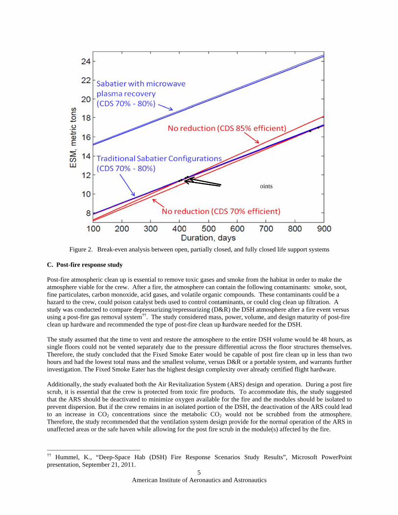
B. Mission Specification and Cost Equivalency Assumptions For this analysis, the architecture of the DSH for a crew of four was investigated for a mission of 100-900 days in duration in order to identify break-even points in technology trades. A volume cost equivalency was applied assuming a hard-shell habitat. Solar photovoltaics with fuel cell storage was assumed as the primary means of harvesting energy. Thermal control was presumed to be achieved using flow-through radiators. Crew time costs were assessed according to the anticipated hours available for the crew to perform maintenance activities for a given mission duration. This number was divided by the total mass of consumables, hardware, and infrastructure for the sized vehicle to provide the mission and configuration specific crew time cost equivalency. The cost equivalency was subsequently applied to the actual expected crew hours required for maintenance of the defined configuration. As a result of these characteristics of the craft, cost equivalencies are summarized in Table 1.
Table 1. Cost equivalencies applied in this analysis. Cost Factor Attribute Value Units Volume, hard shell habitat 66.7 kg/m3 Power, solar voltaic with fuel cell storage 237.0 kg/kW Thermal, flow-through radiators 40.0 kg/kW Crew time, architecture specific * kg/CM-hr
* The crew time cost equivalency is calculated according to the specific life support architecture configuration. In addition, it is worth mentioning that extra-vehicular activity (EVA) was presumably minimal. For missions up to 900 days, only one week of EVA was performed directly from the DSH. This assumption had a signicant impact on the water balance since it eliminates the demand on the water supply for EVA related evaporative cooling. A variety of open, partially-closed, and closed loop architectures were analyzed comparing overall recovery efficiencies for the water system and the efficiency through which carbon dioxide is utilized to feed back into the air subsystem. The analysis also provided cases with and without laundry as well as a variety of oxygen generation and carbon dioxide reduction options. Using the cost factors detailed above, the return on investment for the different architectures was evaluated and compared, as shown in Figure 2. Breakeven points for the open loop and partially closed loop architectures lie close to the 2008 EV5 mission duration, but, most notably, the ESM for the closed loop architectures was considerably higher than those for the open or partially closed systems. This ESM is very large for these architectures because of the power assumption for the plasma reaction and the values may come down as the technology matures. The breakeven dates identified agree well with those of Jones4 for systems employing both carbon dioxide reduction and oxygen generation systems utilizing a urine processor.
Fi
C. Post-fi Post-fire atatmospherefine particuhazard to tstudy was using a posclean up ha The study single flooTherefore, hours and hinvestigatio Additionalscrub, it isthat the ARprevent disto an incrTherefore, unaffected
†† Hummepresentatio
igure 2. Break
re response st
tmospheric clee viable for theulates, carbon mhe crew, couldconducted to cst-fire gas remoardware and re
assumed that tors could not b
the study conhad the loweston. The Fixed
lly, the study ev essential that RS should be dspersion. But ifrease in CO2 the study recoareas or the sa
el, K., “Deepon, September 2
Americ
k-even analysis
tudy
ean up is essente crew. After amonoxide, acid
d poison catalyscompare depresoval system††.
ecommended th
the time to venbe vented separcluded that thet total mass andSmoke Eater h
valuated both tthe crew is pr
deactivated to mf the crew remaconcentrations
ommended thatafe haven while
p-Space Hab 21, 2011.
can Institute of
s between open
tial to remove ta fire, the atmod gases, and vost beds used tossurizing/repre The study con
he type of post
nt and restore thrately due to te Fixed Smoked the smallest vhas the highest
the Air Revitalrotected from tminimize oxygains in an isolas since the mt the ventilatione allowing for
(DSH) Fire R
f Aeronautics a
5
n, partially clos
toxic gases andosphere can conolatile organic o control contamessurizing (D&nsidered mass, -fire clean up h
he atmosphere the pressure die Eater would volume, versusdesign comple
lization Systemtoxic fire produgen available fated portion of
metabolic CO2
n system desigthe post fire sc
Response Sce
and Astronauti
sed, and fully c
d smoke from tntain the followcompounds. Tminants, or cou
&R) the DSH atpower, volum
hardware need
to the entire Differential acrobe capable of s D&R or a poexity over alrea
m (ARS) designucts. To accomfor the fire andf the DSH, the d
would not begn provide for tcrub in the mod
enarios Study
Breakeven Po
ics
closed life supp
the habitat in owing contaminThese contaminuld clog clean tmosphere after
me, and design mded for the DSH
DSH volume woss the floor st
post fire cleanortable system, ady certified fl
n and operationmmodate this,
d the modules sdeactivation ofe scrubbed frothe normal opedule(s) affected
Results”, Mi
oints
port systems
order to make tnants: smoke, snants could be up filtration. Ar a fire event vmaturity of posH.
would be 48 hotructures themsn up in less thaand warrants f
light hardware.
n. During a po the study sugshould be isolaf the ARS coulom the atmoseration of the Ad by the fire.
icrosoft Powe
the soot, a
A versus st-fire
urs, as selves. an two further .
ost fire ggested ated to ld lead sphere. ARS in
erPoint

American Institute of Aeronautics and Astronautics
6
D. Feed-the-Leak Analysis The most credible threat to the integrity of the DSH structure is micrometeoroid impact. If the hull of the DSH were breached, the crew would have two options: try to stay and repair the damage or evacuate. Staying raised the questions of how big of a hole would the pressure control system be able to cover and how long could the system feed the leak. The answers to the first two questions were relevant to the discussion of crew evacuation, and if the crew did seek shelter in the MPCV, the question was raised whether the DSH could be used to accommodate survival in the MPCV in order to return the crew safety from Near Earth Asteriod (NEA). In order to answer these questions, a feed-the-leak analysis was performed. The nominal spacecraft pressure is planned at 10.2 psia, and the analysis evaluated the time for the DSH volume to simply decay from 10.2 psia to 8 psia for a ¼-inch, ½-inch, and ¾-inch holes without providing any make up gas. Results of this study are summarized in Table 2. To determined the realistic feed-the-leak requirement, the team drew upon Space Shuttle heritage using a ¼-inch breach as the defining size. With this, the resulting 3.5 hour time to effect for the ¼-inch breach was more than adequate for the to crew get into a safe haven, don a pressurized suit, identify the leak location, and possibly even repair the leak. As a result, this analysis determined that the ECLSS did not need to carry additional gas to support a feed-the-leak scenario.
Table 2. Amount of time for DSH to depress to 8 psia after hull breach Hole Size (inches)
Time from 10.2 to 8 psia (minutes)
0.25 212 0.50 52 0.75 23
If the crew had to evacuate the DSH and seek shelter within the MPCV, the worst-case scenario would be when the crew is at the asteroid (193 day transit from Earth). The DSH would depress, but in order to accommodate the crew within the MPCV, the life support system within the DSH would have to continue operating. To do this, some redesign would be needed; specifically the MPCV hatch would require penetrations to send waste water out to the DSH processors and send potable water and oxygen back to the crew. In this configuration, the water processor would have to function in a vacuum. The radiation protection “water wall” would also freeze, but this would not matter unless the water/ice could damage needed equipment or this water would be required to supply the consumables to support the crew. Additionally, the MPCV control system would have to be designed to control all needed DSH functions. Because the volume of the MPCV is small, crew provisions (such as food, hygiene, batteries, etc) would still be stored within the DSH. Large umbilicals would be needed in order for the crew to don suits, depress the MPCV, and retrieve the necessary supplies. The feed-the-leak analysis evaluated this scenario and determined that approximately 17 depress/repress cycles would be required to accommodate this. While the quantity of gas necessary to repress one full DSH volume was already accounted for in the total consumable numbers for the vehicle, adding the capability to sustain the crew return from NEA in the MPCV would require a large increase in the total consumable mass and volume to be launched with the DSH. In the end, it was determined by the vehicle team that designing the system for the crew return from a NEA was and unrealistic.requirement to place on ECLSS.
IV. The Design Concept With the results from the analysis of the various architectures, the overall ECLSS design concept for the DSH is a combination of consumable storage and partially-closed recycling system, which is in agreement with a study from Jones9. The details of each of the six subsystems are described below.

A. Air ReAs it is noconsumptioGenerationdrove the nare single-MPCV and
Like the ISfrom the astream andwhich has Carbon D(LPCOR)6 uses the scondensingdesiccant rcabin air isystems to cheapers totechnologi
evitalization Syot practical to on during the n Assembly (Oneed to recover-use or are regd MMSEV veh
SS analog, theair stream priod sent to the w
had problemsioxide Removsystem to rem
same zeolite 5g heat exchanresidual dryer. is then sent torecover hydro
o provide a smes will likely r
Americ
Figure 3
ystem carry all of tmission, the
OGA) water elr as much wategenerable by dhicles and woul
DSH air systeor to entering twaste water tans providing theval Assembly
move CO2 from 5A as the CDnger is remove
This change p the Sabatier p
ogen is too highmall supply ofreduce as the te
can Institute of
3. Integrated A
the necessary air revitalizatectrolysis syst
er as practical, desorbing to spld provide com
em uses a conthe carbon dio
nk for subsequee resources to (CDRA)5, ththe cabin air a
DRA for CO2
ed by a combprovides nearlyprocessor (Figh with little to nf hydrogen to echnologies ma
f Aeronautics a
7
Air and Water
oxygen to protion system retem to provideand as such, dr
pace vacuum, mmonality betw
densing heat eoxide removal ent processingsupport the c
he DSH utilizand supply it toabsorption, th
bination of a Ny a 1/2 ESM s
gure 3). The Eno improvemefeed the Sabatature.
and Astronauti
Systems Conc
ovide pressure elies on the ste the necessarydrove the design
even though tween all of the
exchanger to ctechnology.
g by the water crew of six duzes the Low Po the SOA Sabhe water remaNafion memb
savings over thESM analysis
ent in water rectier system. T
ics
cept
control and ttate-of-the-art y O2. Using wn away from Cthe latter is basystems.
ontrol humidit Water is conrecovery syste
ue to continuedPower Carbonatier processor
aining in the brane bulk dryhe CDRA7. CO
determined thcovery. It was The ESM pena
to support met(SOA) ISS O
water to generCO2 technologiaselined for bo
ty and removendensed from tem. Unlike thd problems win Dioxide Rer. While the LPair stream aft
yer and a NovO2 removed frohat adding reddetermined to
alty for loop-c
tabolic Oxygen rate O2 es that
oth the
e water the air
he ISS, ith the
emoval PCOR ter the velaire om the duction be far
closure
American Institute of Aeronautics and Astronautics
8
B. Water Recovery System The DSH is required to replenish the consumables for both the MPCV (to allow for emergency escape after it arrives) and the MMSEV, which doesn’t have the volume to store all of the consumables needed for the SORTIE missions. The amount of water to meet this requirement is estimated at approximately 450 kg. The water recovery system is responsible for providing this water in addition to that needed by the crew for daily consumption. To accommodate this, the water recovery system will use a combination of both stored and recovered water.
Two large, 450 kg capacity tanks will serve as storage for water. One tank will be launched full to provide the recharge water for the MPCV and the MMSEV, and the second tank will be launched empty to be filled with the extra water produced during the mission by the water processing system.
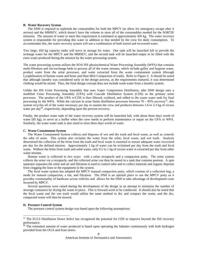
The water processing system utilizes the SOA ISS physiochemical Water Processing Assembly (WPA) that contains multi-filtration and ion-exchange beds to process all of the waste streams, which include galley and hygiene water, product water from the urine processor, and water extracted from the waste containment system (through Lyophilization of human waste and brine and Heat Melt Compaction of trash). Refer to Figure 3. It should be noted that although laundry was considered early in the design process, as the requirements matured, it was determined clothing would be stored. Thus, the final design concept does not include wash water from a laundry system.
Unlike the ISS Urine Processing Assembly that uses Vapor Conpression Distillation, athe DSH design uses a modified Urine Processing Assembly (UPA) with Cascade Distillation System (CDS) as the primary urine processor. The product of the UPA w/CDS is then filtered, oxidized, and added to the waste water tank for final processing by the WPA. While the calcium in urine limits distillation processes between 70 – 85% recovery‡‡, this system recycles all of the water necessary per day to sustain the crew and produces between 1.6 to 2.3 kg of excess water per day§§, respectively, depending upon the percent recovery.
Finally, the product water tank of the water recovery system will be launched full, with about three days worth of water (85 kg), to serve as a buffer when the crew needs to perform maintenance or repair on the UPA or WPA. Similarly, the water water tank is also sized to store three days worth of water.
C. Waste Containment System The Waste Containment System collects and disposes of wet and dry trash and fecal waste, as well as controls
the odor of urine. This system also reclaims the water from the urine, fecal waste, and wet trash. Analysis determined the collection of the brine from the trash and fecal waste is essential to ensure adequate water recovered per day for the defined mission. Approximately 1 kg of water can be reclaimed per day from the trash and fecal waste. Without the brine from trash and solid waste, only 0.5 to 1 kg of excess water is extracted per day from other waste streams.
Human waste is collected in two ways: with a urine receptacle and a compaction potty. The urine system collects the urine via a receptacle, and the collected urine can then be stored in a tank that contains pretreat. A spin separator separates the urine and air and filtration is used to control odor and to collect minerals and organic deposits from clogging the lines or the equipment in the system.
The fecal waste system has adopted the MPCV manual compaction potty, which consists of a collection bag, a mode for manual compaction, a fan, and filtration. The DSH is an optimal place to use the MPCV potty as it provides commonality of hardware across vehicles and allows for the DSH to take advantage of development costs incurred by MPCV.
Several questions were raised during the development of the design in an attempt to minimize the number of stowage containers by drying the waste in place. This is forward work to be conducted. It should also be noted that the fecal waste and the wet trash would utilize the same method to dry and compact the waste, and the dry, compacted waste will then be stowed.
D. Pressure Control System The pressure control system design was based upon the following assumptions:
‡‡ The ECLS Distillation Down Select has recognized the potential for CDS to improve beyond the ISS recovery performance. §§ The estimated amount of water produced is based upon operating the Sabatier continuously with both hydrogen provided from the OGA and from stores.
1) FeM
2) R3) R4) Pr
ex
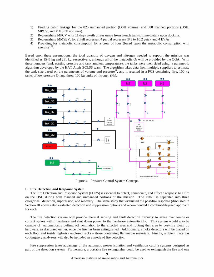
Based upoidentified athese numbalgorithm dthe tank sitanks of lo
E. Fire DThe Fir
on the DScategories:Section IIIfor each.
The fir
current spicapable ofhardware, each floor contingenc
Fire su
part of the
eeding cabin lMPCV, and MMReplenishing MReplenishing M
roviding for mxercise) 10.
on these assumas 1545 kg andbers (tank startdeveloped by tize based on thw pressure O2
etection and Rre Detection anSH during bot: detection, supI above) also ev
re detection syikes within harf automaticallas discussed eaand inside hig
cy analyzers wi
uppression takedetection syst
Americ
leakage for thMSEV volumes
MPCV with 11 dMMSEV: for 2 Fmetabolic cons
mptions, the tod 281 kg, respeting pressure athe HAT Altaihe parameters and three, 100
Fig
Response Systnd Response Syth manned andppression, andvaluated detect
ystem will prordware and shly cutting off arlier, once thegh-risk encloseill also be inclu
es advantage otem. Furtherm
can Institute of
he 825 unmanns). days worth of gFull represses, sumption for a
otal quantity oectively, althouand tank ambier ECLSS teamof volume an
0 kg tanks of ni
gure 4. Pressur
em ystem (FDRS) d unmanned p
d recovery. Thtion and suppr
ovide thermal hut down powe
ventilation to e fire has been ed racks – thosuded as a mode
of the automatimore, a portable
f Aeronautics a
9
ned portion (D
gas usage from4 partial repre
a crew of four
of oxygen andugh all of the ment temperature
m. The algorithd pressure11, aitrogen (N2).
re Control Syst
is essential to portions of the same study thession options
sensing and fer to the hardw
the affected aextinguished.
se containing fe of fire detecti
ic power isolate fire extinguis
and Astronauti
DSH volume)
m launch transitesses (8.3 to 10ur (based upon
d nitrogen nemetabolic O2 we), the tanks w
hm takes data fand it resulted
tem Concept.
detect, annunce mission. T
that evaluated tand recommen
fault detectionware automaticarea and routi Additionally,flammable maion.
tion and ventilsher could be u
ics
and 388 man
t immediately u0.2 psia), and 4 n the metaboli
eeded to suppowill be providedwere then sizedfrom multiple in a PCS con
ciate, and effecThe FDRS is the post-fire rended a combin
n circuitry to scally. This sying that area t smoke detecto
aterials. Finall
lation cutoffs used to extingu
nned portions
upon docking.EVAs.
ic consumption
ort the missiod by the OGA.d using a parasuppliers to es
ntaining five, 1
ct a response toseparated into
esponse (discusned/layered app
sense over temystem would ato post-fire cleors will be placly, ambient tra
systems designuish the fire an
(DSH,
n with
on was With
ametric stimate 100 kg
o a fire o three ssed in proach
mps or also be ean up ced on
ace gas
ned as nd one

will be reqcrew is una
F. VentillIn order touse two 40floors, withfloor will hadjust the however, ndeveloping
Filtration odownstreamblower. Thare dockedsupply por
G. EVA SInitially, thperformed providing hGarment wown oxygedeterminedneeds to prMPCV we
quired per floorable to take act
lation provide suffic00 cubic feet ph each set balahave four suppairflow to indino diverter wg. A system by
occurs at the m of the blowehe DSH is requd. At this timerts have been d
Support he concept of from the MM
high pressure water resupply en compressord by the vehicrovide for conre to sustain a
Americ
r. Fixed fire stion.
cient air supplyper minute (cfmanced by one ply and four reividuals areas
will be able toypass is also pr
inlet from theers. Cabin temuired to provide, the hatches aesigned near th
Figure 5.
f operations foMSEV. With th
oxygen recharfor the MPCV
r and contingecle team that wtingency EVAhull breach.
can Institute of
suppression sho
y to each of them) blowers. Nhigher demandeturn vents, wof the floor. T be completel
rovided to prev
e return air, amperature controde 100 cfm venare not being dhe airlocks to c
Deep Space H
or the stack ofhat, the originage, low pressuV and low preency repress gwhile nominal As from the DS
f Aeronautics a
10
ould be consid
e four floors wiNominally, eacd floor and on
with diverters oThis local conly closed to pvent deadheadin
and the post-fiol is provided bntilation for boesigned to pro
connect the um
abitat Ventillat
f vehicles (MPal requirementure oxygen rechessure oxygen gases. HoweveEVAs would
SH itself when
and Astronauti
dered in the eve
ithin the DSH,ch blower will ne lower demanon each of the ntrol is especialpreclude localing a blower.
ire clean up hby two heat ex
oth the MPCV ovide hard intermbilicals for eac
tion System Co
PCV, DSH, ats for EVA supharge for the srecharge for th
er, as the DSHstill be perforthe MMSEV
ics
ent the vehicle
, the Air Revitasupply the airnd floor (refersupply vents tlly important iized pockets o
hardware is dexchangers, one and MMSEV
rfaces for this ch vehicle.
oncept
and MMSEV) pport from thesuit port seals,he MMSEV –
H design concrmed from theis not docked
e is unmanned
alization Systemr flow for two r to Figure 5). to allow the crin the crew quof trace gases
esigned immeddownstream owhile there veventilation. In
had nominal e DSH only inc and Liquid C
– as MMSEV hcept matured, e MMSEV, the
in the event th
or the
m will of the Each
rew to uarters; s from
diately of each ehicles nstead,
EVAs cluded ooling has its it was
e DSH hat the

American Institute of Aeronautics and Astronautics
11
To accommodate this, the DSH will need at least two suit loop connections for the Advanced Crew Escape Suits and air and water systems provisions for the EVA capable suits (consisting of vacuum umbilicals for the Rapid Cycle Amine CO2 removal system and either vacuum for the Spacesuit Water Membrane Evaporator or a cooling loop).
H. ECLSS Responsibilities per Floor The DSH vehicle design utilizes a vertical shell divided into four floors with a center core used as the crew pass through from one floor to the next and each floor has been assigned a specific function (refer to Figure 6). While the ECLSS needs to provide pressure control, ventilation, and atmospheric control to all of these floors simultaneously, some of the floors have additional requirements from ECLSS, as discussed below.
Since deck 1 includes the galley, the ECLSS must provide potable hot and cold water taps for meal preparation and general consumption. This area must also have provisions for wet and dry trash stowage, and the Heat Melt Compaction may be located on this floor in order to eliminate the need for the crew to haul trash to other floors for processing.
Deck 2 houses the individual crew quarters and has the least amount of services from the ECLSS. There has been considerable discussion regarding locating stored water in this area to provide radiation shielding for the crew. As the ECLSS intends to launch 450 kg of water, this is a possible location for this water, although the exact means of storage (smaller water bags or larger tanks) have not yet been determined. Additional work is needed in this area to discuss recirculation paths and biocide dosing, interconnects between the water storage system and the WRS, MPCV, and MMSEV, as well as redundancy for Loss of Crew (LOC)/Loss of Mission (LOM) considerations.
The majority of the life support hardware with crew interface will be located on the third deck. The waste/hygiene compartment is located on this floor and will provide a hand wash system, body wash system, and commode and urinal systems. Wet trash from wipes as well as human waste will be stowed, if not processed, on this floor. Additionally, interfaces to ventilation for the MMSEV as well as EVA systems will be located on this floor.
Deck 4 is dedicated for stowage and subsystem equipment. The vehicle team would like noisy and dangerous equipment as far away form the crew quarters as reasonable, and although the specific equipment to be located in this area has not yet been determined, this could be the location of the ARS blowers, the Sabatier, the Lyophilization system, and the urine processing hardware. The ventilation umbilical for the MPCV will also be connected to the ARS on this floor.

American Institute of Aeronautics and Astronautics
12
Figure 6. Deep Space Habitat Vertical Orientation Layout
V. LOC/LOM Redundancy The Deep Space Habitat team began with a “rule-based” redundancy plan for the first iteration and intended to perform probabilistic risk assessment on the design in the next iteration to create a risk-informed design. In this mission, a quick abort home was not considered a reasonable response to a failure. As a result, the initial DSH life support design started with two-fault tolerant functionality for loss of crew and single fault tolerant for loss of mission.
The function of “provide atmosphere” is one which would most quickly lead to loss of crew in the event of a failure. Failure to recharge MMSEV tanks to explore the asteroid constitutes loss of mission. Pressure regulators and controllers were installed in redundant, parallel paths. Using more, small nitrogen tanks means that two can fail and still leave enough nitrogen for the mission while increasing mass by a smaller fraction than using 3 systems each sized for the whole mission. Oxygen supply could either be provided through storage tanks or through electrolysis from water. Installing three oxygen generators using recycled water was found to be more efficient than providing stored oxygen for the entire mission with redundant tank quantities. Some oxygen must always be available in a high pressure tank for EVA and MMSEV recharge, and this oxygen could also be used temporarily during the troubleshooting period in the event of an OGA failure.
The function of “provide water” could lead to a loss of crew state after a failure, but in a survival case, a lower water use rate (2 L/CM/d instead of 2.9 L/CM/d) could be implemented. Failure to provide water for the MMSEV recharge causes a loss of mission case. Storing water for the entire mission would be a prohibitively large mass. Instead, recycling water from waste is more cost effective but means that many technologies are now critical to the survival of the crew. Even with recycling systems in place, there are stored volumes of water in the vehicle. The mass balance impacts of technology failure and stored water must be considered together.

American Institute of Aeronautics and Astronautics
13
An analysis of the mass balance was performed to see how critical each functions were at various points in the mission. The wastewater tank and potable water tank for the water processor is assumed to have several days capacity, capable of handling brief downtimes for maintenance or replacing components. Another tank of water in the vehicle stores water for MMSEV recharge. Since that recharge is a fairly large amount of water delivered quickly, it cannot be supplied directly from the water processor. To avoid loss of mission from a single failure, two tanks and parallel delivery paths (regulators, valves) are required. The water processor provides potable water from condensate and other wastewater and must have three parallel processors to be two fault tolerant.
Other technologies, like the urine processor, Sabatier reactor, or waste dryer provide gray water (not potable) to the water processor. The urine processor provides the largest amount of water of the three, estimated at 3.5-4 kg/d. If the urine processor fails early in the mission, but Sabatier and waste drying are still working, there is still not enough water to survive the rest of the mission even if water is left in an MMSEV recharge tank for use. Thus, the urine processor must be two-fault tolerant and have three strings. The Sabatier reactor provides more water than waste drying but also requires more mass and power. If a Sabatier reactor fails, even if the waste dryer is operating, the crew would have to use water reserved for MMSEV recharge to survive. Thus, loss of the Sabatier is loss of mission, and it must have redundant components. But if both Sabatier systems fail and the MMSEV tanks and waste drying functions operate, the crew can survive. The waste dryer is more cost effective for survival than Sabatier, but since the water produced by it is assumed to be lower, failure of the waste dryer does not lead to loss of mission. Therefore, redundant strings are not necessary.
If all of the water processing hardware operates, excess clean water is produced. With this knowledge, only one volume of MMSEV recharge water needs to be available at launch. Without hardware failures, the second tank will be filled with excess clean water over time before the need date. This also leaves the crew with one tank of water even after the MMSEV recharge has occurred. Thus, a single point failure to any recycling function or MMSEV tank should not result in loss of mission, and no two failures in combination can leave the crew without enough water to survive.
VI. Forward Work Work is still needed before NASA can confidently build a life support system for a Deep Space Habitat that will meet all the needs. While this study effort has ended, other organizations are continuing efforts, with the biggest questions remaining are in the reliability of the hardware. Currently other studies are examining probabilistic assessments of state of the art regenerative life support systems, and their lessons learned should be brought to bear on the redundancy and emergency strategy in this design. Technology development groups are refining performance estimates and trying to increase the robustness of their technologies and increase system reliability. In parallel, parametric assessments of other mission architectures continue, and the detailed lessons learned from these studies should be brought into this design as well. As results from all these efforts are revealed, the system design should be refined to create the safest, most reliable, and most efficient way to provide life support for crews venturing beyond Earth orbit.
Nomenclature ALSSAT = Advanced Life Support Sizing and Analysis Tool ARS = Air Revitalization System CDRA = Carbon Dioxide Removal Assembly CDS = Cascade Distillation System Cfm = cubic feet per minute CH4 = Methane CHX = Condensing Heat Exchanger CM = Crew member
= Power equivalency for ESM analysis, [kg/kW] = Cooling equivalency for ESM analysis, [kg/kW] = Crew-time equivalency for ESM analysis, [kg/CM-hr] = Volume equivalency for ESM analysis, [kg/ m3]
CO2 = Carbon Dioxide D&R = Depressurizing and Repressurizing DSH = Deep Space Habitat

American Institute of Aeronautics and Astronautics
14
ECLSS = Environmental Control and Life Support System ESM = Equivalent system mass EVA = Extra-vehicular activity FDRS = Fire Detection and Response System H2 = Hydrogen H2O = Water HMC = Heat Melt Compactor HSIR = Human Systems Integration Requirements ISS = International Space Station IX = Ion Exchange Kg = kilograms LEO = Low Earth orbit LiOH = Lithium Hydroxide LOC = Loss of Crew LOM = Loss of Mission LPCOR = Low Pressure Carbon Dioxide Removal LSS = Life support system M = Mass, [kg] MCV = Microbial Check Valve MF = Multi filtration MPCV = Multi-Purpose Crew Vehicle N2 = Nitrogen NASA = National Aeronautics and Space Administration NEA = Near Earth Asteriod NEO = Near Earth Object O2 = Oxygen OGA = Oxygen Generation Assembly PLSS = Portable Life Support System POU = Point of Use Psia = Pressure, ambient SEV = Space Exploration Vehicle SOA = State of the Art TCCS = Trace Contaminant Control System TRL = Technology Readiness Level TSAC = Temperature Swing Adsorption Compressor UPA = Urine Processing Assembly WCS = Waste Containment System WPA = Water Processing Assembly WW = Waste water VRA = Volitale Removal Assembly
References 1 Levri, J. A., Vaccari, D. A., and Drysdale, A. E., “Theory and Application of the Equivalent System Mass Metric,” 30th
International Conference on Environmental Systems, SAE, Toulouse, France, 2000, Paper No. 2000-01-2395. 2 Levri, J. A., Drysdale, A. E., Ewert, M. K., Fisher, J. W., Hanford, A., Hogan, J. A., Joshi, J. A., and Vaccari, D. A.,
“Advanced Life Support Equivalent System Mass Guidelines Document,” Tech. rep., NASA/TM-2003-212278, 2003. 3 Jones, H. W., “Using Radar Charts to Select Life Support Technology,” 40th International Conference on Environmental
Systems, AIAA, Barcelona, Spain, 2010, Paper No. AIAA 2010-6015. 4 Jones, H. W., “Breakeven Mission Durations for Physicochemical Recycling to Replace Direct Supply Life Support,” 37th
International Conference on Environmental Systems, SAE, Chicago, IL, 2007, Paper No. 2007-01-3221. 5 Williams, D. E., Dake, J. R. and Gentry, G.A., “International Space Station Environmental Control and Life Support System
Status 2009-2010”, 40th International Conference on Environmental Systems, Barcelona, Spain, 2010, Paper No. AIAA-2010-6180-792.
6 Varghese M. M. et al., “Development Status of a Lower-Power CO2 Removal and Compression System for Closed-Loop Air Revitalization”, 40th International Conference on Environmental Systems, Barcelona, Spain, 2010, Paper No. AIAA-2010-6060.

American Institute of Aeronautics and Astronautics
15
7 “Distillation Technology Comparison for Spacecraft Applications”, NASA Johnson Space Center, Houston, Texas, April 2010.
8 Jeng, F.F.,“Assessment of Improvement in Air Drying and Moisture/CO2 Removal Technologies for Carbon Dioxide Removal Assembly (CDRA)”, NASA Johnson Space Center, Houston, Texas, August 2011, ESCG-4470-11-TEAN-DOC-0051.
9 Jones, H.,“Design and Analysis of a Flexible, Reliable Deep Space Life Support System” NASA AMES Research Center, California, September 2011.
10 “Constellation Program Human-Systems Integration Requirements”, CxP 70024D Appendix E, NASA Johnson Space Center, Houston, Texas, December 11, 2009
11 Anderson, M.S., Curley, S., Rotter, H., Stambaugh, I., Yagoda, E.“Altair Lander Life Support: Design Analysis Cycles 4 and 5”, 41st International Conference on Environmental Systems, Portland, OR, 2011, Paper No. AIAA-