Deep Foundation Analysis Systems
18
1 23 Geotechnical and Geological Engineering An International Journal ISSN 0960-3182 Geotech Geol Eng DOI 10.1007/s10706-017-0234-8 Hammer Efficiency and Correction Factors for the TxDOT Texas Cone Penetration Test Rozbeh B. Moghaddam, William D. Lawson, James G. Surles, Hoyoung Seo & Priyantha W. Jayawickrama
Transcript of Deep Foundation Analysis Systems
1 23
Geotechnical and GeologicalEngineeringAn International Journal ISSN 0960-3182 Geotech Geol EngDOI 10.1007/s10706-017-0234-8
Hammer Efficiency and Correction Factorsfor the TxDOT Texas Cone PenetrationTest
Rozbeh B. Moghaddam, WilliamD. Lawson, James G. Surles, HoyoungSeo & Priyantha W. Jayawickrama

1 23
Your article is protected by copyright and
all rights are held exclusively by Springer
International Publishing Switzerland. This e-
offprint is for personal use only and shall not
be self-archived in electronic repositories. If
you wish to self-archive your article, please
use the accepted manuscript version for
posting on your own website. You may
further deposit the accepted manuscript
version in any repository, provided it is only
made publicly available 12 months after
official publication or later and provided
acknowledgement is given to the original
source of publication and a link is inserted
to the published article on Springer's
website. The link must be accompanied by
the following text: "The final publication is
available at link.springer.com”.

ORIGINAL PAPER
Hammer Efficiency and Correction Factors for the TxDOTTexas Cone Penetration Test
Rozbeh B. Moghaddam . William D. Lawson . James G. Surles .
Hoyoung Seo . Priyantha W. Jayawickrama
Received: 30 November 2016 / Accepted: 8 April 2017
� Springer International Publishing Switzerland 2017
Abstract This study analyzes blowcount data from
instrumented Texas Cone Penetration (TCP) tests.
TCP hammer efficiency, rod length influence on the
hammer efficiency, and overburden pressure correc-
tion factors for the TCP blowcounts (NTCP) are
explored. Results are compared to published correc-
tion factors for the standard penetration test (SPT).
The final dataset analyzed for this study consisted of
293 TCP tests from which 135 tests were instru-
mented. TCP hammer efficiency values for automatic
trip hammers ranged from 74 to 101% with an average
of 89%. Analyses showed a statistically-significant
relationship between the TCP hammer efficiency and
the rod length below ground surface. Statistical
models were developed for undifferentiated soils,
and corresponding rod length correction factors for the
TCP test (CR-TCP) were obtained ranging from 0.90 to
1.00. In a second analysis, the relationship between the
overburden pressure and NTCP was explored and a
mathematical expression for the overburden correc-
tion factor for the TCP blowcount value (CN-TCP) was
determined. This work represents the first study where
corrections to NTCP are explored, and the outcome of
this research benefits the geotechnical engineering
community using the TCP test and its associated
foundation design method.
Keywords Texas Cone Penetration test � TCP �Standard penetration test � SPT �Rod length correctionfactor � Overburden correction factor � Hammer
efficiency � Correction factors
List of symbols
a and b Skempton (1986) soil dependent
parameters
Cb Borehole diameter correction factor for
SPT
CI Confidence intervals
CN Overburden correction factor for SPT
CN-TCP Overburden correction factor for TCP
COV Coefficient of variation
Cr Rod length correction factor for SPT
CR-TCP Rod length correction factor for TCP
R. B. Moghaddam (&)
GRL Engineers, Inc., 30725 Aurora Road, Cleveland,
OH 44139, USA
e-mail: [email protected]
W. D. Lawson � H. Seo � P. W. Jayawickrama
TechMRT: Multidisciplinary Research in Transportation,
Texas Tech University, Box 41023, Lubbock,
TX 79409-1023, USA
e-mail: [email protected]
H. Seo
e-mail: [email protected]
P. W. Jayawickrama
e-mail: [email protected]
J. G. Surles
Department of Mathematics and Statistics, Texas Tech
University, Box 41042, Lubbock, TX 79409-1042, USA
e-mail: [email protected]
123
Geotech Geol Eng
DOI 10.1007/s10706-017-0234-8
Author's personal copy

Cs Sampler type correction factor for SPT
DR Relative density
Em Measured hammer energy
Er Hammer efficiency-SPT
Er-TCP Hammer efficiency-TCP
Et Theoretical hammer energy
K Exponent of the power function developed
for overburden correction factor
N1-60 SPT blowcount standardized to 60%
energy and corrected for overburden
N1-60-
TCP
TCP blowcount standardized to 60%
energy and corrected for overburden
N60 SPT blowcount standardized to 60%
energy
N60-TCP TCP blowcount standardized to 60%
energy
NN-TCP Normalized TCP blowcount to a blowcount
corresponding to a reference stress
NSPT SPT blowcount
NTCP TCP blowcount
PI Prediction intervals
SPT Standard penetration test
TCP Texas Cone Penetrometer
z Depth
z1 Depth of interest
zBaseline Depth at which the fitted model has
flattened
b1 Slope for a linear model equation
bo Intercept for a linear model equation
r0v Effective vertical stress
r0ref Reference stress (i.e. 100 kPa, 2000 psf)
r0N Normalized effective vertical stress to a
reference stress
1 Introduction
This paper presents correction factors for blowcount
values (NTCP) from the Texas Cone Penetration (TCP)
test, a dynamic field penetration test which is similar to
yet different from the standard penetration test (SPT).
For over 60 years, the TCP test and its associated
foundation design charts have been used successfully
for the design of drilled shaft and driven pile
foundations that support tens of thousands of bridges
and other major transportation infrastructure through-
out Texas and parts of Oklahoma. Data for this study
were obtained as part of a program of 293 TCP tests
obtained from 21 geotechnical borings in five states
located in the south-central United States. These data
were used to identify the average hammer efficiency
for the TCP test using an automatic hammer, and also
to develop rod length correction factors and overbur-
den pressure correction factors for the NTCP values.
The main purpose of correction factors for field
penetration blowcount values is to achieve consistent
and reliable input data for the foundation design
procedures associated with the tests. In the case of
SPT, several studies have been completed to address
the impact of different factors on the hammer
efficiency which further influences NSPT. In contrast
to SPT, no published work discusses a corrected NTCP
nor addresses the influence of different factors on TCP
hammer efficiency. This paper contributes to the
geotechnical engineering community where the TCP
design charts are used as the primary method for the
design of deep foundations. The factors presented in
this paper help to standardize NTCP and further obtain
accurate design parameters for foundation design
based on the TCP design charts.
The TCP test and its associated foundation design
method are introduced and compared to the SPT to
further highlight similarities and differences. To set the
stage for the analyses presented in this paper, a review
of the history of the TCP test and the development of
correction factors for the SPT are described. Tasks
associated with the field data collection for this study
followed by statistical analyses and results are dis-
cussed in detail. Finally, hammer efficiency for the
TCP test and rod length correction factors for NTCP are
developed and compared to existing factors for the
SPT. Furthermore, the effect of the overburden pres-
sure on the variation ofNTCP is analyzed and discussed.
2 The TxDOT Texas Cone Penetration Test
2.1 Description of the TCP Test
The TCP test is a dynamic field penetration test which
assesses the consistency of the material encountered
during geotechnical exploration. This test method is
documented as TxDOTDesignation Tex-132-E, ‘‘Test
Procedure for Texas Cone Penetration’’ (TxDOT
1999). The TCP test uses a 77.0-kg hammer with
Geotech Geol Eng
123
Author's personal copy

0.61-m drop to force a 7.6-cm diameter steel cone into
the soil or rock formation, Fig. 1.
In current practice, penetration for the TCP test is
performed in three separate increments. The first is to
achieve proper seating, consisting of driving the cone
12 blows or approximately 15-cm, whichever comes
first. The TCP blowcount is then determined as the
sum of the number of blows required to achieve the
second and third 15-cm increments. The total blow-
count or NTCP corresponding to 30-cm penetration is
used to obtain design parameters. In very hard
materials such as rock and intermediate geomaterials
(IGM), after the proper seating process, the cone is
driven 100 blows and the penetration value for the first
and second 50 blows are recorded, with the NTCP value
reported as centimeters of penetration per 100 blows.
2.2 History and Development of the TCP Test
In the 1940s, the newly-formed Bridge Foundation
Soils group of the Texas Highway Department (THD)
Bridge Division identified the need for developing a
unified method for the characterization of geomateri-
als and the design of deep foundations. The TCP test
method was developed by the Bridge Group as an
in situ test method for evaluating the broad range of
geologic materials encountered in foundation con-
struction (TxDOT 2000).
The TCP-based foundation design method was
introduced in the 1956 edition of the Foundation
Exploration and Design Manual (THD 1956). This
manual provided a series of correlation relationships
for foundation design which were established based on
TCP test blowcount data (NTCP) and laboratory-
measured shear strength using the triaxial test proce-
dure (THD 1956). The charts published in 1956 were
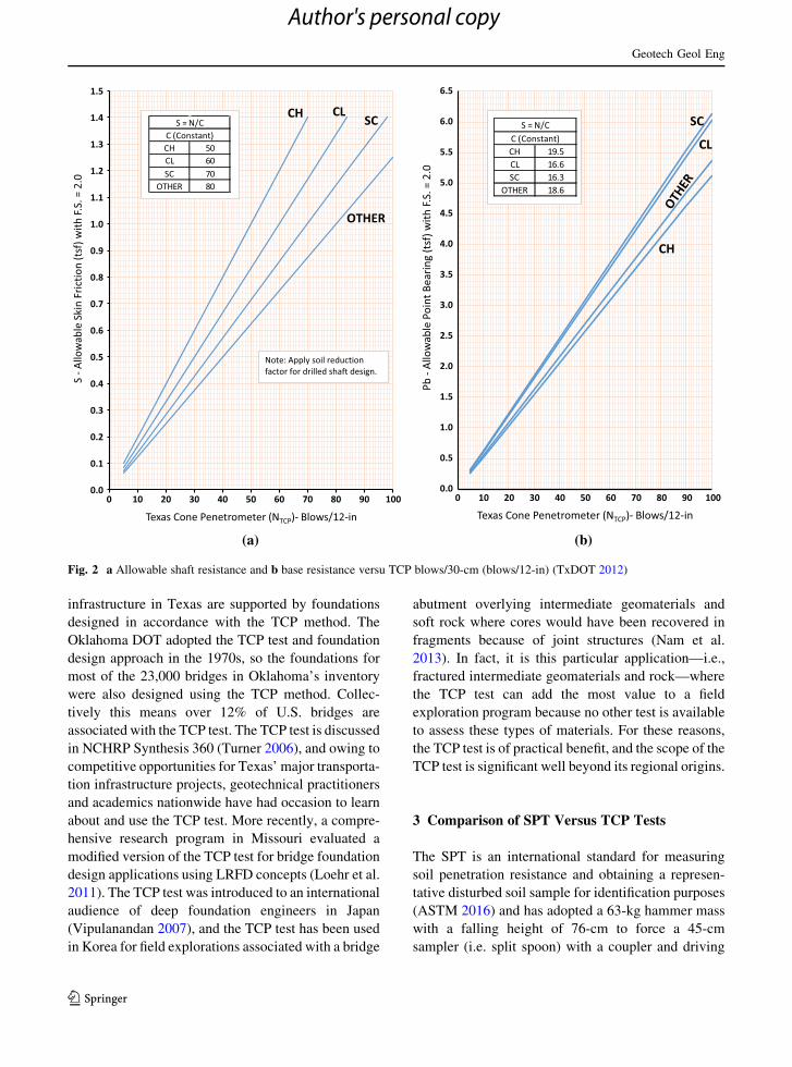
refined in 1972, 2000, and 2012, and two sets of design
charts now exists. The first set was developed for the
prediction of unit shaft resistance (i.e. skin friction)
and unit base resistance (i.e. point bearing) for soils
with TCP blowcounts less than 100 blows/30-cm,
Fig. 2. The second set is for geomaterials with
blowcounts greater than 100 blows/30-cm (i.e. pene-
tration per 100 blows), Fig. 3. The current design
charts reflect the allowable stress design philosophy
and present allowable unit shaft and base resistances
based on NTCP and soil types.
2.3 Application of the TCP Test
The TCP test and its associated foundation design
method have been used regionally, nationally and
internationally. As would be expected with its Texas
roots, the TCP test has seen extensive application
throughout the state to evaluate subsurface materials
ranging from very soft coastal clays, to shales and
weathered/fractured limestones, to hard and brittle
rock. Texas currently maintains over 53,000 bridges in
the National Bridge Inventory (FHWA 2016), and
most of these bridges plus other transportation
Fig. 1 TCP test conical
driving point and field
application. a TCP conical
driving point (Moghaddam
2016), b field application of
the TCP test (Moghaddam
2016)
Geotech Geol Eng
123
Author's personal copy
infrastructure in Texas are supported by foundations
designed in accordance with the TCP method. The
Oklahoma DOT adopted the TCP test and foundation
design approach in the 1970s, so the foundations for
most of the 23,000 bridges in Oklahoma’s inventory
were also designed using the TCP method. Collec-
tively this means over 12% of U.S. bridges are
associated with the TCP test. The TCP test is discussed
in NCHRP Synthesis 360 (Turner 2006), and owing to
competitive opportunities for Texas’ major transporta-
tion infrastructure projects, geotechnical practitioners
and academics nationwide have had occasion to learn
about and use the TCP test. More recently, a compre-
hensive research program in Missouri evaluated a
modified version of the TCP test for bridge foundation
design applications using LRFD concepts (Loehr et al.
2011). The TCP test was introduced to an international
audience of deep foundation engineers in Japan
(Vipulanandan 2007), and the TCP test has been used
in Korea for field explorations associated with a bridge
abutment overlying intermediate geomaterials and
soft rock where cores would have been recovered in
fragments because of joint structures (Nam et al.
2013). In fact, it is this particular application—i.e.,
fractured intermediate geomaterials and rock—where
the TCP test can add the most value to a field
exploration program because no other test is available
to assess these types of materials. For these reasons,
the TCP test is of practical benefit, and the scope of the
TCP test is significant well beyond its regional origins.
3 Comparison of SPT Versus TCP Tests
The SPT is an international standard for measuring
soil penetration resistance and obtaining a represen-
tative disturbed soil sample for identification purposes
(ASTM 2016) and has adopted a 63-kg hammer mass
with a falling height of 76-cm to force a 45-cm
sampler (i.e. split spoon) with a coupler and driving
0.0
0.1
0.2
0.3
0.4
0.5
0.6
0.7
0.8
0.9
1.0
1.1
1.2
1.3
1.4
1.5
0 10 20 30 40 50 60 70 80 90 100
S - A
llow
able
Ski
n Fr
ictio
n (t
sf) w
ith F.
S. =
2.0
Texas Cone Penetrometer (NTCP)- Blows/12-in
CH CLSC
OTHER
CH 50CL 60SC 70
OTHER 80
S = N/CC (Constant)
Note: Apply soil reduction factor for drilled shaft design.
0.0
0.5
1.0
1.5
2.0
2.5
3.0
3.5
4.0
4.5
5.0
5.5
6.0
6.5
0 10 20 30 40 50 60 70 80 90 100
Pb -
Allo
wab
le P
oint
Bea
ring
(tsf
) with
F.S.
= 2
.0
Texas Cone Penetrometer (NTCP)- Blows/12-in
CH
CL
SC
CH 19.5CL 16.6SC 16.3
OTHER 18.6
S = N/CC (Constant)
(a) (b)
Fig. 2 a Allowable shaft resistance and b base resistance versu TCP blows/30-cm (blows/12-in) (TxDOT 2012)
Geotech Geol Eng
123
Author's personal copy

shoe to penetrate into soil strata. The conventional
SPT driving procedure where blows are recorded for
each of three 15-cm increments was introduced in
1954, and the SPT was adopted in 1958 as ASTM
Standard D 1586, ‘‘Standard Test Method for standard
penetration test (SPT) and Split Barrel Sampling of
Soils’’.
The form of the TCP test is similar to the SPT in that
a steel driving point is advanced into subsurface
material at the bottom of a borehole by hammer
strikes, with blowcounts recorded in three 15-cm
increments. However, in certain aspects the TCP test
differs from the SPT. The TCP test does not use a split-
barrel sampler but rather a solid steel conical point
with 60� apex angle, Fig. 1. Hence, the TCP test
cannot and does not collect a soil sample. Also,
because of its more robust solid steel design, TCP test
refusal is defined as resistance to penetration greater
than 100 blows/30-cm, so the TCP test is suitable for
evaluating harder geomaterials and rock. In contrast,
SPT refusal is customarily achieved at resistance to
penetration greater than 50 blows/15-cm, or when
there is no observed advance of the sampler during the
application of 10 successive blows.
Another difference between the SPT and the TCP
test is the magnitude of their blowcount values. The
correlation between NTCP and NSPT is not linear, and
NSPT values are typically 20–60% lower than NTCP
values, other things being equal (Touma and Reese
1972). It is possible to gain an intuitive sense about
this by comparing the hammer energy and the sampler
area for the two tests. The theoretical hammer energy
for the tests is roughly equivalent—475 N-m for the
SPT versus 461 N-m for the TCP. But the cross-
sectional area of the samplers is quite different. The
nominal cross-sectional area for an unplugged SPT
split spoon is 1071 mm2 compared to the TCP conical
point with cross sectional area of 4561 mm2. Thus, it
ought to take a lot less energy to drive an SPT split
barrel sampler than the TCP cone, so SPT blowcounts
should be significantly lower than TCP blowcounts in
the same material. This is in fact the case.
Fig. 3 a Allowable shaft resistance, b allowable base resistance versus TCP penetration/100 blows (TxDOT 2012)
Geotech Geol Eng
123
Author's personal copy

Since the 1970s, research has shown that blowcounts
obtained from theSPT (NSPT) are sensitive to factors such
as hammer energy, rod length, type of soil, borehole
diameter, andothers. In the case of SPTa significant body
of literature and research exists to facilitate direction and
guidance for correcting NSPT values and further use a
standardized NSPT for design. In contrast, for the TCP
test, published work has not been completed exploring
the effects of these same factors, andperhapsother factors
influencing the resistance to penetration.
It is important to mention that throughout this
paper, detailed discussion and mathematical expres-
sions regarding the SPT and the TCP test are
presented. For purposes of clarity and consistency all
factors, equations, and parameters associated with the
TCP test will have the subscript ‘‘TCP’’. Any other
geotechnical field testing parameter presented without
the subscript will be associated with the SPT.
4 Development of Correction Factors for SPT
4.1 Standardization of the SPT Blowcount
To reduce the variability of NSPT due to multiple
factors associated with the test, several researchers
have recommended the standardization of NSPT to a
specific level where the influence of these factors has
been addressed through correction factors. Numerous
technical reports and research studies have been
published addressing the factors that may influence
the NSPT including hammer type, sampler, driving
mechanism, depth of test, borehole diameter, and
physical aspects of tools used during the test. See
Palmer and Stuart (1957), Fletcher (1965), Ireland
(1970), DeMello (1971), Brown (1977), Schmertmann
et al. (1979), Kovacs and Salomone (1982), Seed
et al. (1984), Skempton (1986), Daniel et al. (2004),
Odebrecht et al. (2005), and Schnaid (2009). The work
completed by these researchers mainly focused on the
determination of a standard NSPT where all the
variabilities associated with the test procedure are
accounted for. In later years, this topic continued to
evolve with slightly different focus. Work done by
Aggour and Radding (2001) and Idriss and Boulanger
( 2012) focused on the calibration of NSPT for purposes
of liquefaction and corrections for overburden pres-
sure after the work presented by Skempton (1986).
4.2 Development of Correction Factors for SPT
N-Values
The energy delivered into the drilling rod and the
sampler is impacted by the release method and type of
hammer (Skempton 1986). Based on the results of
studies described above and recommendations pre-
sented bySeed et al. (1984), a correction to theNSPTwas
proposed by Skempton (1986) based on the hammer
energy ratio reported in the United States. The hammer
energy ratio (Er), also termed ‘‘hammer efficiency’’,
refers to the relationship betweenmeasured energy (Em)
and theoretical energy (Et), Er = Em/Et * 100%. NSPT
values with a known energy ratio can be normalized to
60% of hammer efficiency using Eq. (1).
N60 ¼ NSPT
Er
60ð1Þ
In Eq. (1), N60 is the normalized NSPT for 60%
hammer efficiency, NSPT is the SPT blowcount for
30-cm penetration, and Er is the hammer efficiency in
percentage for a specific type of hammer.
In addition to the energy ratio, Skempton (1986)
further developed work done by Schmertmann and
Palacios (1979) who determined that the required energy
to drive the sampler is increased as the rod length
increases. He also considered research completed by
Seed et al. (1984) who showed that approximately 20%
moreblowscorrected for 60%ofhammer efficiencywere
required to drive a SPT sampler with a liner. From this
work, Skempton (1986) determined correction factors for
rod length, sampler type, and borehole diameter, and
modified Eq. (1) by introducing correction factors:
N60 ¼ NSPT
Er
60CrCbCs ð2Þ
In Eq. (2), Cr, Cb, and Cs are correction factors to
the SPT blowcounts to account for rod length,
borehole diameter, and type of sampler, respectively.
These corrections have appeared in standard geotech-
nical textbooks such as Geotechnical Engineering:
Principles and Practice by Coduto et al. (2011) and
Fundamentals of Geotechnical Engineering by Das
and Sobhan (2014).
Geotech Geol Eng
123
Author's personal copy

4.3 The Overburden Pressure Correction for SPT
According to Meyerhof (1957) the penetration resis-
tance increases linearly with depth, and at a constant
vertical stress, the resistance to penetration also
increases at a rate approximately equal to the relative
density squared, Eq. (3).
NSPT ¼ D2R aþ br0
v
� �ð3Þ
In Eq. (3), a and b are soil-dependent factors, DR is
the relative density, and r0v is the effective vertical
stress at the depth of test.
The effect of overburden pressure on the NSPT is
further expressed by introducing a correction factor
for overburden pressure (CN). Skempton (1986)
presented results of two trials completed for sand
deposits with different particle size. For these trials, a
laboratorymodel was built where the variation of NSPT
with depth was determined while maintaining a
constant relative density (DR) of the sand. During
the second trial, the test was carried out with different
relative densities of the sand. The results followed the
relationship presented by Meyerhof (1957) shown in
Eq. (3). In addition, results from field testing at
different sites were compared to the laboratory model
leading to the development of an overburden correc-
tion factor CN. With the overburden pressure correc-
tion factor, the NSPT and N60 can further be corrected
as shown in Eqs. (4) and (5).
N1�SPT ¼ CNNSPT ð4Þ
N1�60 ¼Er
60CrCbCsCNNSPT ð5Þ
In Eq. (4) N1-SPT refers to SPT blowcounts cor-
rected for overburden pressure. In Eq. (5) N1-60 refers
to SPT blowcounts corrected for both 60% hammer
efficiency and overburden pressure. Researchers have
developed many expressions for CN where results
have been supported by laboratory models and field
test results. Table 1 presents a summary of typical
expressions developed for CN.
4.4 Contemporary Practice for Correcting SPT
Blowcount Data
According to Schnaid (2009), in current practice, the
SPT is the most common and popular in situ test
method to obtain subsurface information and predict
soil strength parameters. As comparator and to assess
the standard practice of corrected or normalized NSPT,
geotechnical manuals published by all 50 State DOTs
were reviewed. Results show that 72% of the state
DOTs specify correction factors shown in Eq. (2) and
further correction for effect of the overburden pressure
using Eq. (4) is suggested. For the selection of design
parameters, the N1-60 value is used. Furthermore, in
some states such as Florida, the specification requires
the consultants to report NSPT in the boring logs but
mandates the design of all elements to be based on N1-
60. Also, most DOTs require the consultant to show
proof of calibration of the hammer prior to any work
completed for the agency.
5 Corrections to TCP Blowcount
5.1 Need for TCP Correction Factors
The predictive allowable foundation capacity models
represented in both SPT and TCP foundation design
methods source to empirical data obtained during an
era when the use of conventional donut hammers and
safety hammers was a standard practice for the
completion of geotechnical field penetration tests.
Because of similarities between SPT and TCP test
procedures where hammer, anvil, drill rod, and
blowcounts are common aspects in both tests, it is
reasonable to consider that all uncertainties and
variabilities associated with the SPT could very well
be present in the TCP test. Therefore, blowcounts
obtained from both SPT and TCP tests using today’s
automatic hammers should be corrected to a standard
measurement of blowcounts.
5.2 TxDOT Policy
TxDOT’s current Geotechnical Manual (2012) pre-
sents the guidelines for the use of TCP as a field test
and further refers to TEX 132-E as the approved TCP
test method. The use of an automatic hammer is
specified in the Geotechnical Manual, but neither the
Geotechnical Manual nor the test method provides
information regarding the need for correction of NTCP
or evaluation of the hammer efficiency. The use of an
automatic trip mechanism is specified to ensure the
0.61-m required falling height, and this requirement is
part of TxDOT’s current geotechnical service
Geotech Geol Eng
123
Author's personal copy
contracts. Further, TxDOT’s current geotechnical
service contracts require that drilling subcontractors
provide annual certification of TCP hammer
efficiency.
6 Research Design and Method
6.1 The TCP Reliability Research Study
The dataset for this paper was obtained from a research
study where the reliability of the TCP foundation
design method was assessed (Seo et al. 2015). Based
on the energy data and soil information collected
during field operations for that study, a complemen-
tary research study was designed to further explore the
TCP test hammer efficiency (Er-TCP), rod length
correction factor (CR-TCP), and overburden pressure
correction factor (CN-TCP). A dataset of 293 TCP tests
was compiled. These data source to 21 geotechnical
borings at 16 different sites in the states of Louisiana,
Arkansas, Missouri, New Mexico and Texas as shown
in Table 2.
6.2 Field work and TCP Blowcount Data Sources
Per TxDOT Geotechnical Manual, TCP tests were
performed at 1.5-m intervals throughout the borings
starting at the depth of 1.5-m below the ground surface
and ending at the maximum depth of boring. For
identification and classification of the subsurface
materials associated with the TCP test, disturbed
samples were collected using either SPT split-spoon or
thin-walled tube samples obtained directly below the
TCP test without having cleaned out the borehole. The
sole purpose of the disturbed samples was to identify
and classify the material associated with each TCP test
at depth.
Throughout the geotechnical drilling and sampling
phase, four different drill rigs, each one equipped with
an automatic CME-hammer, were used. For the
borings completed in Missouri and Arkansas North-
east, AWJ1 rod was used; whereas, the rest of the
borings were carried out using NWJ2 rod. Prior to
drilling operations, the automatic hammer was disas-
sembled and the hammer mass was weighed to ensure
conformance with TCP test standards (i.e. Tex-132-
E).
6.3 Hammer Energy Readings
Force, acceleration, and rod length were measured for
all TCP tests at 3.0-m intervals using the SPT
Analyzer. This device includes a subassembly of a
0.61-m length of drill rod that is instrumented with two
strain gage bridges and two piezo-resistive accelerom-
eters. These sensors obtained measured force and
Table 1 Summary of
existing overburden
correction factors (CN)
Reference CN Observations
Peck et al. (1974) 0:77log 20r0v
r0v in tsf
Seed et al. (1984) 1� 1:25logr0v r0
v in tsf
Tokimatsu and Yoshimi
(1983)
1:70:7þr0
v
r0v in kg/cm2
Skempton (1986) 200100þr0
vDR = 40–60% and NC Sand
300200þr0
vDR = 60–80% and NC Sand
17070þr0
vfor OC Sand
r0v in kPa
Liao and Whitman (1986)ffiffiffiffiffiffi100r0v
qfor NC Sand
r0REF
r0v
h ikfor k = 0.4 to 0.6
r0v in kPa
Clayton (1995) 14343þr0
vfor OC Sand r0
v in kPa
Robertson et al. (2000) r0v
r0atm
h i�0:5
for NC Sandr0v in kPa
1 AWJ refers to conventional taper threaded drill rod—outside
diameter 44.5 mm, thread pitch 5.1 mm.2 NWJ refers to conventional taper threaded drill rod—outside
diameter 66.7 mm, thread pitch 6.4 mm.
Geotech Geol Eng
123
Author's personal copy

velocity signals for each hammer blow and transferred
the data to the SPT-Analyzer console. These data were
collected and processed using the Pile Dynamics. Inc.
(PDA 2013) software which analyzes the force and
acceleration recorded by the console for each hammer
blow. The theoretical energy was determined from the
product of weight of the hammer and the drop
distance, measured during field operations.
After completion of field operations, data related to
type of soil, drill rod size, drilling fluid, and depth were
carefully logged and recorded. Also, necessary data to
perform analyses on hammer efficiency were stored in
the SPT-analyzer console. These data were used to
assemble the final dataset analyzed for this study.
6.4 The TCP Blowcount Dataset
The final dataset consisted of 293 TCP tests compris-
ing 251 tests completed in soils and 42 in IGM/rock.
From the 293 TCP tests, 135 tests were instrumented
to obtain energy measurements using the SPT Ana-
lyzer, with 119 instrumented tests in soils and 16
instrumented tests in IGM/rock. Because the IGM/
rock data were limited and showed high variability,
the study presented in this paper focuses solely on
soils. Therefore, TCP blowcounts corresponding to the
IGM/rock materials have not been included in the final
dataset, and as observed in Fig. 4a, maximum TCP
blowcounts reported are less than or equal to 100
blows per 30-cm of penetration. For the 119 instru-
mented TCP tests in soils (i.e. the data used for this
study), the hammer energy for each TCP hammer
strike was recorded resulting in 4901 hammer energy
measurements, with the average hammer efficiency
for each TCP test plotted in Fig. 4b.
7 Results from TCP Blowcount Data
A series of factors associated with the completion of
the TCP test impacts the energy transferred to the TCP
cone and thereby influences the measured NTCP
blowcount values. Following the customary standard-
ization process for correcting NSPT blowcounts iden-
tified in Eq. (5), this paper presents TCP hammer
efficiency data, correction factors for rod length, and
correction factors for overburden pressure. Correction
factors for borehole diameter and sampler type are not
presented however, since for the TCP study the
borehole diameter was constant for all sites, i.e.
10-cm, and the factor for type of sampler does not
apply since the TCP point is a solid steel cone.
7.1 Hammer Efficiency for the TCP Test (Er-TCP)
All TCP tests performed for this study were completed
using Central Mine and Equipment (CME) automatic
hammers where the hammer mass is lifted by a
Table 2 Field research sites and related TCP-borings
State site location Geotechnical
borings
TCP tests in
soils
TCP tests in
rock/IGM
Instrumented TCP tests
in soil
Instrumented TCP tests in
rock/IGM
Missouri—
Warrensburg
2 2 8 1 4
Missouri—
Frankford
2 0 16 0 7
Texas—Houston 1 12 0 7 0
Arkansas—Siloam
Springs
2 5 9 2 0
Arkansas—
Monticello
2 37 0 20 0
Arkansas—Turrell 2 38 0 20 0
Louisiana—Various 7 102 0 50 0
New Mexico—
Various
3 55 9 19 0
Total 21 251 42 119 16
Geotech Geol Eng
123
Author's personal copy

hydraulically-operated chain cam mechanism and the
hammer is released using an automatic finger cam,
allowing the hammer to fall and impact an anvil
located at the head of the drill string.
Figure 4b illustrates the TCP hammer efficiencies
measured in this study. Using Minitab 17.3.1 (2016)
basic statistical parameters such as mean and coeffi-
cient of variation (COV) for the TCP hammer
efficiency were determined. Hammer efficiency val-
ues of all measurements without differentiating soil
types range from 74 to 101% with mean of 89% and
COV of 0.046. These are associated with TCP
blowcounts ranging from 3 to 100 with an average
of 38 blows/30-cm and measured at depths ranging
from 3- to 30-m, average 13-m. Each data point
represents the mean hammer efficiency for an indi-
vidual TCP test. This was determined from the ratio of
measured energy based on the SPT analyzer to the
theoretical energy calculated for the TCP hammer
system (and also verified by field measurements) for
each hammer strike associated with a test. TCP
hammer efficiency values ranged from 74 to 101%
with an average of 90% and COV of 0.041 for coarse-
grained soils, and from 77 to 97% with an average of
88% and COV of 0.04 for fine-grained soils.
As has been noted, the TCP hammer is heavier and
the drop is shorter compared to the SPT. The TCP
hammer efficiency values presented herein are similar
in range but about 7% higher on average than SPT
hammer efficiency values published in the literature.
For example, Honeycutt et al. (2014) report energy
transfer data from a research database for CME
automatic hammers and consisting of energy mea-
surements from 17,825 individual SPT hammer blows
(analogous to the 4901 hammer energy measurements
obtained for this TCP study). Their dataset shows an
average energy ratio of 82.9%, with a coefficient of
variation of ±0.074. In contrast to the SPT where
numerous studies exist that identify hammer effi-
ciency, the data presented herein represent the first
published TCP hammer efficiency values.
7.2 Development of Rod Length Correction
Factors (CR-TCP)
The relationship between the rod length and hammer
efficiency has been explored considering that the rod
length correction for NTCP will follow a similar form
as the correction for NSPT. A linear model was created
for all the geomaterials analyzed in this study based on
an equation following the form presented by Eq. (6):
Er�TCP ¼ b0 þ b1 log zð Þ ð6Þ
In Eq. (6), Er-TCP is the average hammer efficiency
for the TCP test, b0 and b1 are coefficients which will
differ based on the soil type, and z is depth, i.e. length
0
5
10
15
20
25
30
35
0 25 50 75 100
Dept
h (m
)TCP Blowcount Values (NTCP)
0
5
10
15
20
25
30
35
0.7 0.8 0.9 1
Dept
h (m
)
Average Hammer Efficiency
(a) (b)
Fig. 4 Compiled dataset. a TCP blowcount values NTCP, b average hammer efficiency
Geotech Geol Eng
123
Author's personal copy

of rod below ground surface. To develop rod length
correction factors, Eq. (6) is written for any depth and
a baseline depth. In this context, the baseline depth
refers to a depth at which the model line is flattened. At
this depth (i.e. baseline depth) the correction factor
would be considered as unity. The subtraction of
Eq. (6) written for any arbitrary depth from Eq. (6)
written for the baseline depth can be represented by
Eq. (7):
D ¼ Er�TCP at z1 � Er�TCP at zBaseline¼ b1 log z1ð Þ � log zBaselineð Þð Þ ð7Þ
In Eq. (7), z1 is the depth of interest and zBaseline is
the depth at which z1 is compared against. Identifying
an estimate and confidence interval (CI) for D requires
finding an estimate and confidence interval for b1. Forthis analysis Minitab 17.3.1 (2016) was used to
determine the value of b1 for each type of soil with a
95% confidence interval. Substituting lower and upper
endpoints of the CI in Eq. (7) will result in a 95% CI
for D. The result of this operation is an estimate and CI
for the correction factor for rod length (CR-TCP)
determined by Eq. (8):
Cr�TCP ¼ logEr�TCP at z1
Er�TCP at zBaselineð8Þ
In Eq. (8), CR-TCP is the correction factor for rod
length, and Er-TCP is the average hammer efficiency for
the TCP test at the corresponding depth.
7.3 Presentation of TCP Rod Length Correction
Factors
Considering that the TCP design charts were gener-
ated during a period of time when the use of hammers
with nominal average efficiency of 60% was consid-
ered as the standard practice, it is reasonable to
consider the normalization of the hammer efficiency
for the TCP test by rewriting Eq. (1) for the TCP test:
N60�TCP ¼ NTCP
Er�TCP
60ð9Þ
In Eq. (9), N60-TCP is the TCP blowcount standard-
ized for 60% of hammer efficiency, NTCP is the TCP
blowcount, and Er-TCP is the hammer efficiency for the
TCP test in percent.
After standardization of the NTCP for 60% of
hammer energy, Eq. (2) can be rewritten for the TCP
test, Eq. (10).
N60�TCP ¼ NTCP
Er�TCP
60Cr�TCP ð10Þ
Rod length correction factors (CR-TCP) were devel-
oped by analyzing values corresponding to a baseline
depth of 24-m and using the models shown in Eqs. (7)
and (8). For this study, the baseline depth was
considered as the rod length below ground surface at
which the model flattened and presented a linear
tendency. Figure 5 presents average hammer effi-
ciency versus rod length below the ground surface.
Figure 5 presents two rod length correction
datasets side-by-side, the SPT dataset (Skempton
1986) and the TCP dataset for this study. For the TCP
data, the solid line represents the predictive model
created based on Eq. (6) with an R-square value of
0.43, p value of 0.000 (p value\0.0001), and the 95%
CI boundaries are represented by the dashed lines
closer to the model line. Results for the TCP test
suggest that the lowest data variability is presented at
depths greater than 24-m where the depth correction
factor is unity. In case of the SPT, it is noted that the
model line flattens for depths greater than 10-m.
Furthermore, observing the depth correction factors
for each test at the same depth, a difference in value is
observed. This difference could be primarily associ-
ated with the hammer used for the test and the type of
samplers. The dataset analyzed by Skempton (1986)
0.00
10.00
20.00
30.00
40.00
0 0.2 0.4 0.6 0.8 1 1.2
Rod
Leng
th B
elow
Gro
und
Surf
ace
(m)
Average Hammer Efficiency
Fine Grained Soils
Coarse Grained Soils
TCP-Model Line
Confidence Intervals
Predic�on Intervals
Skempton (1986) Model
Skempton (1986)S= 0.0337R2= 43.4%p-value= 0.000
Fig. 5 Scatterplot of average efficiency versus rod length for all
soils
Geotech Geol Eng
123
Author's personal copy

was based on SPT data obtained using a safety
hammer; whereas, the data analyzed in this study
were obtained from TCP tests completed using an
automatic hammer.
Table 3 presents details of the TCP rod length
correction factors. As analyzed in this dataset, coarse-
grained soils consisted of poorly graded sands (SP),
silty sands (SM), and clayey sands (SC) with SP being
the predominant soil type. For the coarse-grained
soils, rod length correction factors (CR-TCP) were
obtained ranging from 0.92 to 1.01. Similarly, the
types of soil described as fine-grained consisted of
lean clay (CL), fat clay (CH), and a low plasticity silt
(ML) with CL being the predominant soil. For the fine
grained soils, rod length correction factors (CR-TCP)
were obtained ranging from 0.90 to 1.01. A statistical
test established that there are no significant differences
between the correction factors for the coarse and fine
soils based on calculated probability p greater than
0.05 (p value = 0.48).
Considering the narrow range of rod length correc-
tion factors for differentiated soils (i.e. fine grained
and coarse grained soils), the factors recommended
correspond to the model developed for undifferenti-
ated data with values ranging from 0.9 to 1.0 as shown
in Table 3.
7.4 Development of Overburden Pressure
Correction Factors (CN-TCP)
To develop the overburden correction factor for the
TCP test, Eqs. (4) and (5) can be rewritten for the TCP
blowcounts (NTCP):
N1�TCP ¼ CN�TCPNTCP ð11Þ
N1�60�TCP ¼ Er
60Cr�TCPCN�TCPNTCP ð12Þ
The relationship between standardized TCP blow-
counts (N60-TCP) and TCP test blowcounts corrected
for overburden pressure (N1-60-TCP) can be defined as
the overburden correction factor for the TCP test.
1
CN�TCP
¼ N60�TCP
N1�60�TCP
ð13Þ
In order to develop the correction factor for
overburden pressure, a reference stress value should
be defined first. In this study, the atmospheric pressure
(100-kPa) is taken as the reference stress (rref)
following the standard practice for SPT. Therefore,
N60-TCP value obtained at a vertical stress of 100 kPa
becomes a reference value (N60-TCP-ref) for the devel-
opment of overburden correction factor. Then, three
main steps were followed to develop overburden
correction factors for the TCP test (CN-TCP). These
steps were: (1) normalizing the TCP blowcounts with
respect to N60-TCP-ref, (2) normalizing the effective
vertical stress with respect to rref, and (3) determining
the relationship between Steps (1) and (2). Prior to these
steps, all TCP blowcounts (NTCP) were corrected for
hammer efficiency and rod length following Eq. (10).
Step 1 Normalized TCP Blowcounts (NN-TCP)
For each TCP boring included in the compiled dataset,
the relationship between N60-TCP and the effective
vertical stress (r0v) was analyzed and a linear regres-
sion model was developed as shown in Fig. 6.
Table 3 Rod length correction factors (CR) for TCP and SPT
Depth (m) CR-TCP Depth (m) CR-SPT
Coarse grained Fine grained Undifferentiated Recommended Undifferentiated soil type
3 0.92 0.90 0.90 0.90 3–4 0.75
6 0.94 0.93 0.94 0.94 4–6 0.85
9 0.96 0.95 0.95 0.95 6–9 0.95
12 0.97 0.97 0.97 0.97 [9 1.00
15 0.98 0.98 0.98 0.98 [9 1.00
18 0.99 0.99 0.99 0.99 [9 1.00
21 0.99 0.99 0.99 0.99 [9 1.00
24 1.00 1.00 1.00 1.00 [9 1.00
27 1.00 1.01 1.01 1.00 [9 1.00
30 1.01 1.01 1.01 1.00 [9 1.00
Geotech Geol Eng
123
Author's personal copy

From the interception of the horizontal dashed line
depicting the reference stress of 100-kPa and each
solid line depicting the linear model fitted to the data
corresponding to each boring, the N60-TCP-ref corre-
sponding to the reference stress was determined. At
the end of this step, each boring was associated with
one TCP blowcount value (N60-TCP-ref) and this value
was used for the normalization of the TCP
blowcounts:
NN�TCP ¼ N60�TCP
N60�TCP�ref
� �ð14Þ
Step 2 Normalized Effective Vertical Stress (r0N)
Based on available geotechnical information for each
site, unit weights were assigned to each soil layer. In
the case where measured unit weights of soil were not
available, correlations published by TxDOT (2000)
and Bowles (1996) were used to estimate the soil unit
weight. For all TCP tests, the effective vertical stress
was calculated at the depth of test. Furthermore, the
effective vertical stress values determined in this step
were normalized to a reference stress of 100 kPa using
Eq. (15) below:
r0N ¼ r0
v
rref
� �ð15Þ
Each normalized effective vertical stress (r0N) was
then associated with its corresponding normalized
TCP blowcount.
Step 3 Relationship between NN-TCP and r0N
After completion of Steps 1 and 2, a scatterplot was
generated with NN-TCP (=N60-TCP/N60-TCP-ref) as
dependent variable and r0Nð¼r0
v=r0refÞ as the inde-
pendent variable and the relationship between these
variables was further analyzed. Figure 7 presents a
scatterplot for NN-TCP versus r0N together with the
fitted regression curve from a power model.
Linear and polynomial regression models were fit
to the dataset, and it was observed that a key
assumption of regression was violated; namely that
of a constant (stable) variance. The variance issue was
addressed by log10 transformation of the dependent
and independent variables, and statistical models with
reliable confidence intervals were determined. After
the transformation, a model was generated for the
dataset following Eq. (16) and converted from log10scale back to natural scale to obtain Eq. (17), which
0
50
100
150
200
250
300
350
400
0 50 100 150 200 250 300 350
σ'v
(kPa
)
N60-TCP
WAR-1 Turrell-1 Turrell-2 Monticello-1Monticello-2 Crosby-1 Ragley-1 Essen Lane-1Highlan Park-1 Causeway BLVD-1 Causeway Bridge-1 I49 US71-1Sunland Park-1 ABQ-1 Ohkay Owingeh-1 I-49 Unknown Pond-1
Reference Stress (Pa), 2000 psf
Fig. 6 N60-TCP and
effective vertical stress
relationship for each TCP
boring
Geotech Geol Eng
123
Author's personal copy

indicates a power function relationship between NN-
TCP and r0N. Figure 7 presents the model fitted to the
dataset based on Eq. (16) illustrated by the solid line
including its corresponding 95% confidence intervals
(CI) identified by dashed lines.
log10 NN�TCPð Þ ¼ 0:73log10 r0N
� �ð16Þ
N60�TCP
N60�TCP�Ref
� �¼ r0
v
rref
� �0:73
ð17Þ
7.5 Overburden Correction Factor CN-TCP Results
From the combination of Eqs. (13) and (17), the
overburden correction factor for the TCP test (CN-TCP)
is obtained as follows.
CN�TCP ¼ 1
r0v
rref
� �0:73ð18Þ
Equation (18) represents a power function which is
the recommended overburden correction factor for the
TCP tests with a power (k) of 0.73. To provide context,
the expression determined for CN-TCP in this study was
compared to the models published for CN for SPT
shown in Table 1, by plotting the effective vertical
stress (r0v) versus CN, as shown in Fig. 8.
Figure 8 illustrates the relationship between the
effective vertical stress and the overburden correction
factors published for the SPT compared to the
overburden correction factor for the TCP presented
in this paper. The relationship for the TCP test is
shown with the solid line with 95% CI dashed lines.
From the comparison, it is noted that the overburden
correction factors presented by other researchers for
the SPT data vary between 0.35 and 2.1; whereas, the
correction factors for the TCP test range from 0.4 to
3.05 for the vertical effective stress range of
30–330 kPa. It is inferred that the broad spectrum of
the overburden correction factor for the TCP test may
be associated with the fact that the TCP test data
analyzed in this study included both fine-grained and
coarse-grained soils whereas the factors developed for
the SPT included coarse-grained soils only.
8 Other Factors that May Influence TCP Test
Hammer Efficiency
Analyses of the TCP test data, observations of the TCP
field procedure, and comments in the technical
literature suggest that factors other than those cor-
rected for herein could create variability in the NTCP.
Four additional factors—drill rod size, type of soil,
drilling fluid, and depth—were identified and analyzed
to explore their influence on TCP hammer efficiency.
Statistical analyses using ANOVA were performed
using SAS9.3 (2015) and Minitab 17.3.1 (2016) to
0
0.5
1
1.5
2
2.5
3
3.5
4
0 1 2 3 4 5
σ 'v/
σ're
fN60-TCP/N60-TCP-Ref
Coarse Grained Soils Fine Grained SoilsTTU-TCP Model Confidence Intervals
R2= 30% p-value=0.000k = 0.73
N60-TCP/N60-TCP-Ref = (σ'v/σref)0.73
Fig. 7 Scatterplot for normalized NN-TCP versus normalized
effective vertical stress r0N
0
50
100
150
200
250
300
350
400
0 0.5 1 1.5 2 2.5 3 3.5
σ'v
(kPa
)
CN
Peck et. al. (1974)
Seed (1976)
Tokimatsu (1983)
Skempton(1986) DR=40-60%
Skempton(1986) DR=60-80%
Skempton (1986) OC Sand
Liao Whitman (1986)
Clayton (1993)
TTU-CN-TCP
TTU-CN-TCP-Confidence Intervals
Fig. 8 Effective Vertical Stress (r0v) versus CN for TCP and
SPT
Geotech Geol Eng
123
Author's personal copy

study the effect of drill rod size, type of soil, drilling
fluid, and depth, on the hammer efficiency. For this
process, the hammer efficiency was considered as
dependent variable and all other factors as indepen-
dent variables/factors. This ANOVA also tested for
interactions between these factors. A three-way inter-
action is observed between drilling fluid, soil type, and
depth. This implies that each of these are associated
with hammer efficiency. Furthermore, drill rod size is
involved in two significant two-way interactions,
which implies that it is also associated with hammer
efficiency.
Results from these analyses indicate that a statis-
tically significant relationship exists between the
identified factors and hammer efficiency, but because
the data were obtained from a field-oriented study and
not a controlled experiment, the exact nature of these
relationships could not be determined. Hence, to
develop correction factors that account for all the
variables influencing TCP hammer efficiency, addi-
tional study is required where the research design
allows each factor to be analyzed independently.
9 Summary and Conclusions
This paper presents TCP hammer efficiency data, rod
length correction factors, and overburden correction
factors for instrumented TCP tests completed in
coarse-grained and fine-grained soils. Other factors
that may influence TCP hammer efficiency were also
identified.
A dataset of 293 TCP tests comprising 251 tests
completed in soils and 42 in IGM/rock was compiled
for this study. From the 293 TCP tests, 135 tests were
instrumented to obtain energy measurements using the
SPT Analyzer, with 119 instrumented tests in soils and
16 instrumented tests in IGM/rock. An adjusted
dataset of 251 TCP tests were considered for the
development of overburden correction factors for the
TCP test in soils. A total of 119 instrumented TCP
tests in soils were used for the analysis corresponding
to the rod length correction factors.
Undifferentiated efficiency values range from 74 to
101% with mean of 89% and COV of 0.046 associated
with TCP blowcounts ranging from 3 to 100 with an
average of 38 blows/30-cm and measured at depths
ranging from 3- to 30-m, average 13-m. TCP hammer
efficiency values ranged from 74 to 101% with a mean
of 90% and COV of 0.04 for coarse-grained soils, and
from 77 to 97% with an average of 88% and COV of
0.041 for fine-grained soils. These TCP hammer
efficiency values are similar in range but about 7%
higher on average than efficiency values for automatic
SPT hammers published in the literature.
Rod length correction factors for the TCP hammer
efficiency (CR-TCP) were developed by creating a non-
linear model based on statistical analyses. Rod length
correction factors ranging from 0.90 and 1.00 for
undifferentiated data were determined and recom-
mended for the TCP test.
In a separate set of analyses, the relationship between
N60-TCP and soil overburden pressure was analyzed.
Correction factors for the overburden pressure for the
TCP test (CN-TCP) were developed and normalized to a
reference stress (100 kPa). The CN-TCP expression
recommended in this paper is a power function with
k = 0.73, and this is generally in agreement with the CN
expressions published for the SPT.
Although the TCP test is in some ways similar to
the SPT, the two tests are not the same, even though
results from both tests are regularly used to design
deep foundations. Therefore, it makes sense to take
steps to ensure reliable data. In case of the TCP test, up
until now, no published corrections for raw blowcount
data existed. The work presented in this paper is
intended as an initial step to further refine the TCP-
based design method to achieve more reliable design
of deep foundations.
Acknowledgements The authors express their gratitude to the
Texas Department of Transportation for sponsoring the TCP
Reliability research study. The authors also thank Terracon, PSI,
Rick Coffman (University of Arkansas), The Arkansas State
Highway and Transportation Department, the Missouri
Department of Transportation, the Louisiana Department of
Transportation and Development, and the New Mexico
Department of Transportation for their collaboration
throughout the TCP Reliability research project.
References
Aggour MS, Radding WR (2001) Standard penetration test
(SPT) correction, Report No. MD02-007B48, Maryland
State Highway Administration, Baltimore
ASTM International (2016) Standard test method for standard
penetration test (SPT) and split-barrel sampling of soils,
test method D1586-11. ASTM International, West Con-
shohocken, PA
Geotech Geol Eng
123
Author's personal copy
Boulanger RW, Idriss IM (2012) Probabilistic standard pene-
tration test-based liquefaction-triggering procedure.
J Geotech Geoenviron Eng 138(10):1185–1195
Boulanger RW, Idriss IM (2015) CPT-based liquefaction trig-
gering procedure. J Geotech Geoenviron Eng 10:1061
Bowles JE (1996) Foundation analysis and design, 5th edn.
McGraw-Hill, New York
Brown RE (1977) Drill rod influence on standard penetration
test. J Geotech Eng Div 103(11):1332–1336
Clayton CR (1995) The standard penetration test (SPT): meth-
ods and use (No. R 143). Construction Industry Research
and Information Association
Coduto DP, Yeung MCR, Kitch WA (2011) Geotechnical
engineering: principles and practices, 2nd edn. Prentice
Hall, New Jersey
Daniel CR, Howie JA, Campanella RG, Sy A (2004) Charac-
terization of SPT grain size effects in gravels. In: Second
international conference on site characterization (ISC’2)
Das BM, Sobhan K (2014) Principles of geotechnical engi-
neering, 8th edn. Cengage Learning, Connecticut
DeMello VF (1971, June) The standard penetration test. In:
Proceedings of the 4th Pan-American conference on soil
mechanics and foundation engineering, San Juan, PR,vol 1,
pp 1–86
FHWA (2016) National bridge inventory. bridges and struc-
tures, safety, bridge inspection. U.S. Department of
Transportation, Federal Highway Administration, Wash-
ington, DC
Fletcher GF (1965) Standard penetration test its uses and abuses.
J Soil Mech Found SM4, Paper 4395
Honeycutt JN, Kiser SE, Anderson JB (2014) Database evalu-
ation of energy transfer for central mine equipment auto-
matic hammer standard penetration tests. ASCE J Geotech
Geoenviron Eng 140(1):194–200
Idriss IM, Boulanger RW (2012) Examination of SPT-based
liquefaction triggering correlations. Earthq Spectra
28(3):989–1018
Ireland HO, Moretto O, Vargas M (1970) The dynamic pene-
tration test: A standard that is not standardized. Geotech-
nique 20(2):185–192
Kovacs WD, Salomone LA (1982) SPT hammer energy mea-
surement. J Geotech Eng 110(4):562–564
Liao SS, Whitman RV (1986) Overburden correction factors for
SPT in sand. Journal of Geotech Eng 112(3):373–377
Loehr JE, Bowders JJ, Ge L, Likos WJ, Luna R, Maerz N,
Rosenblad BL, Stephenson RW (2011) Engineering policy
guidelines for design of drilled shafts. Missouri Depart-
ment of Transportation, Final Report for Project
TRyy0922, Report cmr12003
Meyerhof GG (1957) Discussion on research on determining the
density of sands. In: Proceedings of 4th international con-
ference of soil mechanics and foundation engineering
Moghaddam RB (2016) Evaluation of the TxDOT texas cone
penetration test and foundation design method including
correction factors, allowable total capacity, and resistance
factors at serviceability limit state. Doctoral dissertation,
Texas Tech University
Nam MS, Park YH, Park YS (2013) Prediction of end bearing
capacity for pre-bored steel pipe piles using instrumented
SPT rods. J Korean Geotech Soc 29(12):105–111
Odebrecht E, Schnaid F, Rocha MM, de Paula Bernardes G
(2005) Energy efficiency for standard penetration tests.
J Geotech Geoenviron Eng 131(10):1252–1263
Palmer DJ, Stuart JG (1957) Some observations on the standard
penetration test and a correlation of the test with a new
penetrometer. In: Proceedings of 4th international confer-
ence on soil mechanics and foundation engineering, p 231
Peck RB, Hanson WE, Thornburn TH (1974) Foundation
engineering, vol 10. Wiley, New York
Robertson PK, Sully JP, Woeller DJ, Lunne T, Powell JJM,
Gillespie DG (2000) Estimating coefficient of consolida-
tion from piezocone tests. Can Geotech J 29(4):539–550
Schmertmann JH, Palacios A (1979) Energy dynamics of SPT.
J Geotech Eng Div 105(8):909–926
Schnaid F (2009) In situ Testing in Geomechanics: the main
tests, 1st edn. Taylor & Francis, London and New York
Seed HB, Tokimatsu K, Harder L, Chung RM (1984) The
influence of SPT procedures in evaluating soil liquefaction
resistance. Report, University of California Berkley,
Earthquake Engineering Research Center, 84–15
Seo H, Moghaddam RB, Surles JG, Jayawickrama PW, Wood
TA, Lawson WD (2015) Reliability based deep foundation
design using texas cone penetrometer (TCP) test: volume 1,
development of load test dataset. DRAFT Report. FHWA/
TX-14-0-6788-1-Vol. 1. Texas Tech University Center for
Multidisciplinary Research in Transportation, Lubbock,
TX
Skempton AW (1986) Standard penetration test procedures and
the effects in sands of overburden pressure, relative den-
sity, particle size, ageing and over-consolidation.
Geotechnique 36(3):425–447
Standard Guide to Standard Penetration Test Analyzer (2013)
Pile Dynamics Inc
Texas Highway Department (1956) Foundation exploration and
design manual, Bridge Division, Texas Highway
Department
Texas Department of Transportation (1999) Geotechnical
manual
Texas Department of Transportation (2000) Geotechnical
manual
Texas Department of Transportation (2012) Geotechnical
manual. Texas Department of Transportation
Tokimatsu K, Yoshimi Y (1983) Empirical correlation of soil
liquefaction based on SPT N-value and fines content. Soils
Foundations 23(4):56–74
Touma FT, Reese LC (1972) The behavior of axially loaded
drilled shafts in sand, Report No. CFHR 3-5-72-176-1
University of Texas Center for Highway Research
Turner J (2006) Rock-socketed shafts for highway structure
foundations. NCHRP synthesis 360. A synthesis of high-
way practice. Transportation Research Board,Washington,
DC
Vipulanandan C(2007) Recent advances in designing, moni-
toring, modeling and testing deep foundations in North
America. In: Kikuchi Y, Otani J, Kimura M, Morikawa Y
(eds) Advances in deep foundations: proceedings of the
international workshop on recent advances of deep foun-
dations (IWDPF07), Port and Airport Research Institute,
Yokosuka, Japan, 1–2 February, 2007. Taylor and Francis
Group, London
Geotech Geol Eng
123
Author's personal copy