DEDICATION - Research in Innovation, Design and ... · Web viewDefense & space system, networked...
75
A Visual Studio Add-In for Software Component Services in Smart Devices Master Thesis (D Level) Student Saud Ur Rehman (791014-6799) [email protected] Supervisor Frank Luders [email protected] 1 School of Innovation, Design and
-
Upload
hoangthuan -
Category
Documents
-
view
215 -
download
0
Transcript of DEDICATION - Research in Innovation, Design and ... · Web viewDefense & space system, networked...

A Visual Studio Add-In for Software Component
Services in Smart Devices
Master Thesis
(D Level)
Student
Saud Ur Rehman
(791014-6799)
Supervisor
Frank Luders
School of Innovation, Design and Engineering
Mälardalen University, Sweden
1
School of Innovation, Design and Engineering

DEDICATION
I would like to dedicate this thesis to
my beloved Mother and Family.
2

Acknowledgement
All praise to all mighty Allah, the most merciful and most beneficial, who has given me
the strength to complete this thesis.
I owe my deepest gratitude to my thesis supervisor Frank Lüders for his exceptional
support and guidance throughout my thesis work. It was an honor for me to work under
his supervision. I would also like to show my gratitude to the school of innovation,
design and engineering at Malardalen University Sweden for providing me with
opportunities and resources to successfully complete this thesis.
I am indebted to many of my colleagues and friends to morally support me and give me
their valuable advices from time to time. Last but not the least I would like to thank my
family for their patience and encouragement.
Saud Ur Rehman
Malardalen University
Vasteras, Sweden.
3

Abstract
Reusability, reliability and flexibility are the key concerns in component based
development. Moreover components should not affect the functionality of other
components. So to address these issues software component models were introduced.
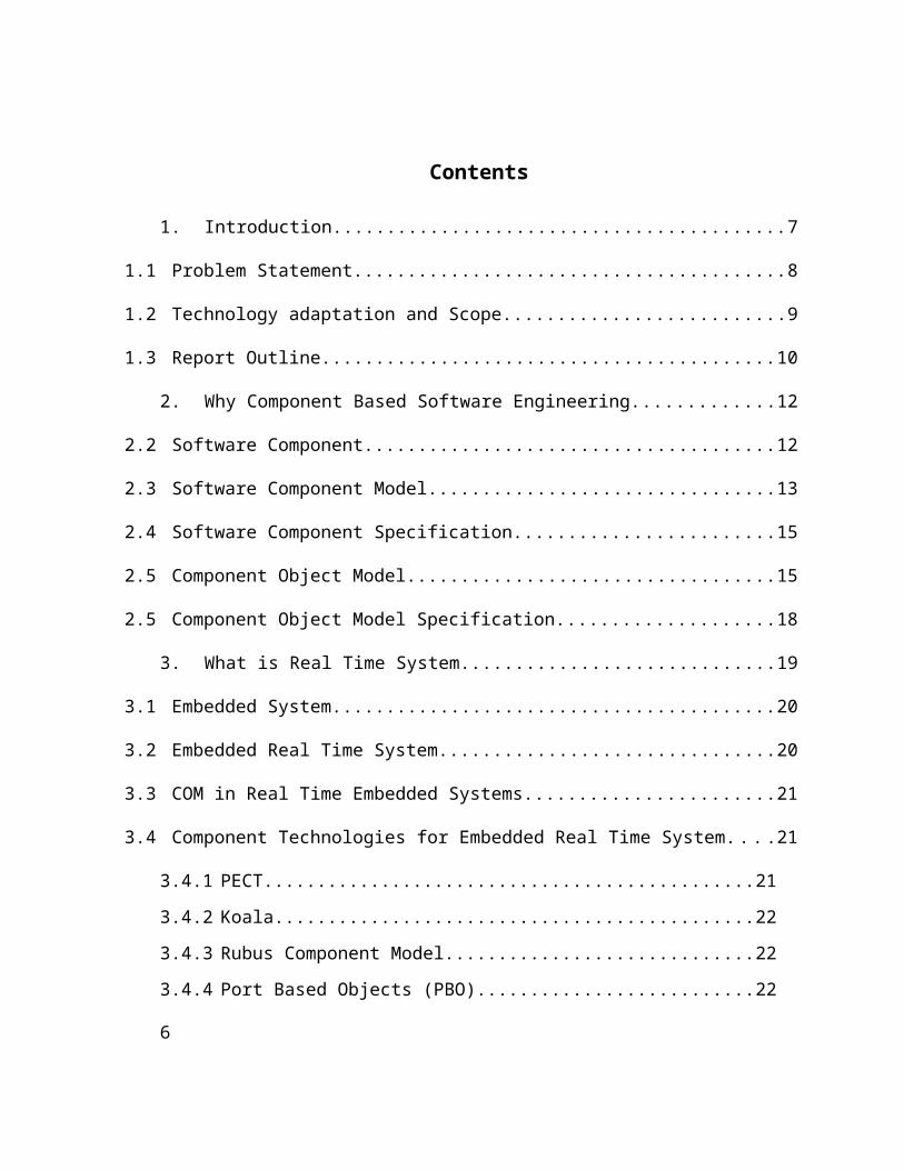
This component based approach is also used in embedded real time systems. But due to
recourse restrictions, traditional component models have a small domain. This problem is
resolved by introducing a new software component services approach extending the
functionality of already available component models. In my thesis I created a visual
studio add-in which extended the functionality of a COM type library and provided the
logging service for ATL smart device. It reads the classes and methods of the COM type
library and then adds logging service using proxy objects. Then I tested my add-in with a
managed client of a simple calculator. First I used the simple COM type library with the
managed client and then I used it with my add-in’s output. The result in both cases were
same so it’s clear that my add-in didn’t alter the basic functionality of the COM type
library it just added the logging service to it.
4
Contents
1. Introduction................................................................................................................7
1.1 Problem Statement............................................................................................................8
1.2 Technology adaptation and Scope....................................................................................9
1.3 Report Outline.................................................................................................................10
2. Why Component Based Software Engineering.......................................................12
2.2 Software Component.......................................................................................................12
2.3 Software Component Model...........................................................................................13
2.4 Software Component Specification................................................................................15
2.5 Component Object Model...............................................................................................15
2.5 Component Object Model Specification.........................................................................18
3. What is Real Time System......................................................................................19
3.1 Embedded System...........................................................................................................20
3.2 Embedded Real Time System.........................................................................................20
3.3 COM in Real Time Embedded Systems.........................................................................21
3.4 Component Technologies for Embedded Real Time System.........................................21
3.4.1 PECT...............................................................................................................21
3.4.2 Koala...............................................................................................................22
3.4.3 Rubus Component Model................................................................................22
3.4.4 Port Based Objects (PBO)...............................................................................22
3.4.5 PECOS............................................................................................................23
3.4.6 CORBA Based Technologies..........................................................................23
3.5 Software Component Services for Real Time Embedded System..................................23
3.5.1 Logging service...............................................................................................24
3.5.2 Synchronization...............................................................................................24
5
3.5.3 Execution Time Measurement........................................................................24
3.6 Proxy Object...................................................................................................................24
4. A Visual Studio Add-In for Software Component Services in Smart Devices.......26
4.1 Visual Studio...................................................................................................................27
4.2 Extensibility....................................................................................................................27
4.3 What is Visual Studio Add-Ins.......................................................................................28
4.4 User Manual for Add-In..................................................................................................28
5. Test Example...........................................................................................................33
5.1 Header file.......................................................................................................................36
5.2 CPP File..........................................................................................................................38
5.3 Code Generator Header File...........................................................................................41
5.4 Code Generated CPP File...............................................................................................44
6. Conclusion and Future Work...................................................................................48
7. References................................................................................................................49
6

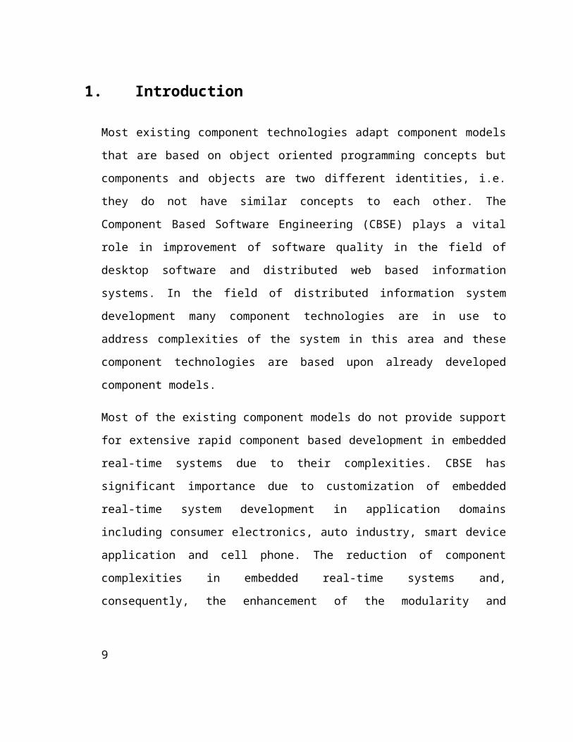
1. Introduction
Most existing component technologies adapt component models that are based on object
oriented programming concepts but components and objects are two different identities,
i.e. they do not have similar concepts to each other. The Component Based Software
Engineering (CBSE) plays a vital role in improvement of software quality in the field of
desktop software and distributed web based information systems. In the field of
distributed information system development many component technologies are in use to
address complexities of the system in this area and these component technologies are
based upon already developed component models.
Most of the existing component models do not provide support for extensive rapid
component based development in embedded real-time systems due to their complexities.
CBSE has significant importance due to customization of embedded real-time system
development in application domains including consumer electronics, auto industry, smart
device application and cell phone. The reduction of component complexities in embedded
real-time systems and, consequently, the enhancement of the modularity and reusability
in these systems, are highly supported by ‘Component Based Development’ (CBD).
Embedded real-time software components have restricted features due to resource
constraints like limited computing, storage, power resources of the target systems. Due to
these constraints, component models and software components developed for embedded
real-time systems support static component architecture. Furthermore proxy objects are
created to add ‘dynamic component architecture’ feature that support Software
Component Services [23].
Component Based Software Engineering for Embedded Real Time System has become
the hot topic from last few years in the software field. Due to the excessive use of
embedded real time system in every field of life CBSE has become an interesting and
important topic in research field. There are a lot of component models available in the
market today, such as COM+, DCOM, COM, CORBA, .NET Component Model,
7

JavaBeans and OMG’s etc. In general CBSE is all about defining the set of rules and
standards for component development, integration and deployment, so a component
model provides us these set of rules and standards. Moreover these models provide a
platform or runtime environment for development and execution of components. The
adaptations of CBSE in embedded real-time systems development have significant risks
and many costs effective parameters which are must be carefully evaluated [4]. For
execution of component standardized runtime environment required that includes domain
specific runtime services, specification of interfaces for general services. Component’s
domain specific services include – for communication purpose message queues, remote
event-based notification and in case of distributed system security services are provided
additionally. Component’s general services include object creation, object lifecycle
management, licensing and object persistence support. The most important phase in
Component Based Development (CBD) is design’s description, in which component
general to domain specific services are standardized, e.g. in distributed system
implementing additional domain specific services like component’s infrastructures and
horizontal services that support additional functionalities across multiple domain system
and system and interface management services may based on component’s general
model. Most popular and practical used component models likes Microsoft’s COM,
DCOM, COM+, .NET Component Model, Sun’s JavaBeans and Enterprise JavaBeans
provide support for similar services in distributed systems that are useful in multiple
domains. For more domain specific services all major component model also provide
vertical services and define standards for component’s interaction and composition in
telecommunication, healthcare and financial base distributed system implementation [24].
1.1 Problem StatementFollowing are the main goals and objective of thesis:
The purpose of this Master thesis is to make a Visual Studio Add-In that targets smart
device projects in Visual Studio and proxy objects are generated and compiled off-line
before being deployed to the target system. More specifically, the Visual Studio Add-In
generates files and adds these file to already existing ATLSmartDevice project.
8
As a minimum, the new Visual Studio Add-In must be able to generate code for a simple
logging service for the following types of components:
COM components, which may run on systems where the .NET Compact Framework is
not available.
The output from the Visual Studio Add-In should be a set of source files and header files
for a Visual Studio ATL smart device solution, that can be compile with ATL Smart
Device project.
To make the tool less dependent on the file formats of a specific version of Visual Studio,
the files should be generated by invoking Visual Studio's automation object model.
1.2 Technology adaptation and ScopeAfter discussion with project supervisor, I decided to use MS Visual Studio.NET 2008
professional edition for development of Visual Studio Add-In that generates proxy object
for ATLSmartDevice COM dll. MS Visual Studio.NET 2008 Professional is latest and
upgraded edition that supports .NET compact framework for smart device application
development, debugging and deployment.
My Visual Studio Add-In generates proxy object files by invoking Visual Studio’s
Automation Object Model, so that file format is less dependent on the file format of
specific version Visual Studio.NET. I also used MS Visual Studio.NET 2008 for testing
& evaluation of my thesis implementation. I developed ATL Smart Device COM
component & Managed COM client application for testing purpose in MS Visual
Studio.NET 2008.
COM ATL Smart device component exist in the form of COM type library, I developed
Visual Studio Add-In to read both metadata/.NET assembly of .NET smart device
component and ATL smart device COM type libraries. In COM/DCOM custom type
definitions and object’s properties and methods are put or store in type library in the form
of interfaces and client application can access these interfaces at runtime. COM client
application access COM component’s interfaces and invoke an object’s method.
9

The main functional requirement of my thesis, to design Visual Studio Add-In that targets
ATL smart device COM component and generates proxy object with simple logging
services of selected function/method or interface by invoking Visual Studio’s automation
object model, so that output should less dependent on the file format of a specific version
of Microsoft Visual Studio.NET. During investigation I found that Microsoft Visual
Studio.NET 2008 automation object model not support to create ATL smart device
Visual Studio project at runtime. For that reason, first I created ATL smart device Visual
Studio project manually in Microsoft Visual Studio.NET 2008. My Newly developed
Visual Studio Add-In first opens ATL smart device Visual Studio project then
creates/generates C++ source, header proxy object files, and other relevant files and
makes changes in ATL smart device Visual Studio project. In remaining section of this
thesis I try to discuss in detail about ATL COM components and shortly about .NET
assemblies.
1.3 Report OutlineIn chapter 2 I started with discussing about some basic concepts of component based
software engineering. Then I discussed about general software component models and
their specification. Afterwards I discussed about the Component Object Model (COM)
and then I described its specifications.
In chapter 3 I discussed real time systems and embedded systems in general. Then I
talked specifically about embedded real time systems and component technologies used
for such systems. Afterwards I discusses about software component services and proxy
objects.
In chapter 4 I discussed MS Visual Studio add-in in general and then I discussed and
explained the working and usage of visual studio add-in for software component services
in smart devices.
10

In chapter 5 I presented the test scenario of my application and discussed about the
testing procedure and the output.
In chapter 6 I have discussed the limitations and future work for this project.
Chapter 7 is for the references.
11

2. Why Component Based Software Engineering
Enormous development and revolutionary changes have been observed in software
engineering in recent decade. Dependency on software has increased and involvement of
software in almost every industry has become almost indispensable. However large
software is used to solve the industrial or some other problems. Large sizes of software
make it complex. This complexity increases the ratio of software failures. These factors
have a great role in the successful software development like budget, deadline, quality,
according to requirements and maintenance. Many of software projects were failure due
to unable to meet their deadlines, out of their budget boundary like etc. There was a need
how to overcome this increasing failure rate. This need takes to move the whole scenario
towards reusability. But this reusability was not fulfilling the whole requirements of that
problem. So a concept of component based software engineering was introduced for this
purpose. In this mechanism a huge application divide into small components. Each
component treats as separate and work independently and it can be used individually or
also integrate with other component for developing a large application [4]. CBSE is
differnet from traditional Software Develovpemnet approach because in which Software
can be devloped from scratch . CBSE based on the idea where Software system depends
upon selecting off-the-shelf component and assembling those components in the well-
defined form of softwre architecture [5].
2.2 Software ComponentSoftware Component is small part of large application. Software Component can be
easily deploying in any environment. A software component can be access with its
interfaces. Interfaces are totally different from component implementation [4].
Microsoft defines the software component in COM (Component Object Model) context is
“A piece of compiled software, which is offering a service” [7].
12

This definition explains the software component in simple and brief way. Software
component is itself a independent software application which provide separate output. It
can be developed and deployed independently within another large application. All the
CBSE (Component Based Software Engineering) revolve around the component. A
component consider as core of CBSE [4].
Another famous definition of components is “A software component is a unit of
composition with contractually specified interfaces and explicit context dependencies
only. A software component can be deployed independently and is subject to composition
by third party” [4].
This definition emphasizes on the independent deployment feature of the software
component. A software component communicates with its environment through its
interface. The encapsulation feature provide a way by which environment can’t access
directly component implementation. Another feature of software component of its
independent nature. A good component is those which can be easily integrate or deploy.
There is no need to recompile the whole application at the addition of new component
[4]. According to functionality software component divide into two types. i) General
component. Class frame works, C++list templates and user interface widgets are the
examples of general components. ii) Implementation component. Source or executable
code, interface specification, code templates and interface specification are the examples
of Implementation component [4]. A software component can easily replace with other
component in a large application without breaking the normal sequence. This feature
shows the substitute nature of the component.
2.3 Software Component Model“A component model specifies the standards and conventions that are needed to enable
the composition of independently developed components “[21]. The standards which a
component model describes are plays important role in the creation of component from
scratch level and also specify the whole communication between the components in a
13

system. These standards are very helpful for implementation, composition and
deployment of a component. These component models play a very important role in the
industrial based component software engineering. Component Models provide the
standard how to successfully compose the existed or newly created component. Due to
this mechanism a boost is exposed in the component based software development. These
standards emphasize on the reusability of components and minimize the precincts of
object oriented programming. In other words we can say Component Model plays an
important role in the field of Component Based Software Development. These
Component Models are JavaBeans Component Model, COM, DCOM, MTS, COM+,
CCM, .NET Component Model and OSGI Component Model etc. In respect of their key
features every component model has importance in the field of component based software
development.
In 1997 sun introduced the JavaBeans component model. As compare to other industrial
component model it is famous due to its simplicity. It is a platform independent
component model and written in Java. It is normally used for designing the GUI
(Graphical User Interface) .There are three major features set of properties, set of
methods and set of events which a JavaBeans fire [22]. Microsoft introduced COM as
component mode in 1995. First time it introduces the feature of program independent.
After that Microsoft enhanced its feature with distribution and new version DCOM
introduced. Component model remain same but only change occur in the framework. But
enhancement process not stopped. A new version MTS was introduced with transaction
services. COM+ is the currently enhanced version of this chain [4].
Microsoft also introduced another component model .NET component model. Because
COM was not become famous due to its limited binary interoperability and introspection.
Like Java Byte Code, .Net component model has internal MSIL (Microsoft Intermediate
Language) for interoperability. And CLR (Common Language Runtime) is for
introspection. It performs the functionality like Java Virtual Machine. Another
component model is OSGI which was introduced in 1999. Its major feature, there is no
need of high memory it can be run on low memory therefore OSGI focused on frivolous
14

framework. Component developed from this model supports dynamic behavior of
architecture of system therefore any update in the component state can be easily done
without interruption or shutdown the system [4].
2.4 Software Component SpecificationIn Component based software engineering (CBSE) specification of software component
has big importance. A software component can be classified into two parts User view and
Developer view. Normally a software component consists of two thing an executable
code and set of interfaces by which a component can communicate with other application
or components. So the executable code is related to developer and interfaces provide all
the related information about component operations to user. And in this context we can
say a software component specification is relevant to component interfaces. In fact any
component specification provides exact description of that component’s action/operation
and context dependencies. A component developer and user take help from this brief
information or software specification. Normally for user point of view a specification
provide the information about definition of interface and component operations. But for
developer point of view specification provide the brief information about internal
structure of the component [4].
There are three types of Component specification a) syntactic specification b) semantic
specification c) Extra functional specification.
b) No doubt syntactic specification is widely used as compare to semantic specification.
Component Object Model specification is based on syntactic specification.
2.5 Component Object ModelComponent Object Model is also called as COM. It is an Object Oriented System,
architecture and framework that is used to create the binary software components. It is a
platform-independent system. Rather than object oriented language it is a standard
[9].COM framework support the interoperability and reusability of distributed
15

components. Due to this, expectations of the developer are going to maintainability and
adaptability. COM concentrates on basic problems that are related to component base
software. These four problems are given below:-[10].
• Basic component interoperability
• Versioning
• Language independence
• Transparent cross-process interoperability.
Generally communication or interaction between components has an importance. Before
the COM a Dynamic Data Exchange (DDE) system is used for interposes
communication. Microsoft introduced COM framework at the release time windows 3.1
round 1993. Class id is used as a identifier in COM component. Components perform
their functionality through interface. Every interface has its own unique id. Interface
methods perform a major role for accessing a COM component [11].
COM object internally has independent nature. Any language can be used for
implementation. COM has a feature that a client can’t access the actual data of COM
object. Client can communicate with object via set of related interfaces. Every interface
stores the information about standard methods in Dynamic Dispatch table. Due to the
object oriented nature interface inheritance is possible with addition of new methods in
Dynamic Dispatch Table (DDT). This type of inheritance is known as single-inheritance.
However multiple inheritances are possible but it’s a complex task. A number of
Dynamic Dispatch table that jointly inconsistency with each other can be extend at a
time. Querying 3 for interfaces is a mechanism by which desired multiple inheritance
results achieved. Normally each interface has three basic standard methods in DDT.
These methods are query, addref and release [12].
All the required administrative facilities provided by these methods. The first slot of DDT
is allocated to query method. An object sends and receives the request to other objects by
query method. In the specification of COM normally query method is known as 16
QueryInterface. Sometime query method generates an error message if requested
interface does not support with object. The other two standard methods addref and
reference normally work for controlling the object life with the help of counting of
reference. After using the COM object a client used the release method for destroy the
object. If client want to give this reference to anyone else like third party then both
parties add reference in addref method. After the utilization of this object they used
release method for destroy or release the object. No doubt garbage collection techniques
are used to automatically handle the life of objects. But some time cycles developed
between the objects. It’s done normally when two different objects hold each other by
reference and state of both objects remains same. In this situation garbage collection
techniques not work automatically and manual method is required to avoid this cycle’s
problem. Memory management is directly affected on any application and component
performance. A successful component or application is that which can manage the
memory in an efficient way. Component Object Model provides a mechanism for
memory management and references. In this context COM provides three basic
parameters which perform their duty regarding memory management and references.
These parameters are in, out and in-Out [12].
COM object also provide a mechanism for error handling. In this mechanism a standard
describe known as 32-bit namespace error code. COM maintains this namespace into two
categories for error handling. One category is known as globally-unique, centrally
allocated error codes and second one is called interface-specific error codes [12]. COM
provides an object model and programming requirements by which their objects
interrelate with other objects. Smalltalk and C++ provide a simple mechanism by which
implementation of COM object can be done. However C, Java and VBScript can also be
used for creation and using of COM component [14]. Microsoft provides a method in the
form of COM by which object in different network or spaces can communicate with the
help of their methods. COM provides a mechanism by which operating system work
under a scenario in which an object creates or destroys automatically according to their
need [13].
17

A major advantage of COM is garbage collection by which object destroys automatically
when no outstanding reference is available [13]. dll hell is known as the foremost
drawback when COM is compared with .NET. In this scenario when a dll or COM
objects are used as common component in different application. If an application update a
new version of shard COM component the other application which is not support the new
version works no longer. So in this case many applications that depend upon that
common component stop their working [15].
2.5 Component Object Model SpecificationCOM specification is like a same as other component specification. Microsoft provides
standard for interoperability in the form of Component Object Model. These standards
are very useful for creation of reusable libraries. Run time interaction is the feature of
these libraries. Another feature of these libraries there is no need to compile when we add
them in our application. These binary standards are also useful for different operating
system and hardware platform. COM specifies the mechanism which makes sure the
reusability of software among the different platforms. Inter component communication in
the form of call function is done by the help of COM binary standards. COM also
specifies a way that distinguishes between component and interface. These standards
describe a way to map the group of strongly-type functions into an interface. COM also
provides a mechanism where different parts work together for application development.
[20]
18
3. What is Real Time System
Real Time System increasingly got the importance in daily life. Most of the field like
Science, Health, defense, air traffic control system and automobile where use of RTS is
rapidly increased.
As compare to other Computational System, the success of Real Time System is not only
depend upon the correctness of functionality or output there is also a need of correct
result with care of time deadline.
Definition (Young 1982) “Any information processing activity or system which has to
respond to externally generated input stimuli within a finite and specified period “[17].
According to this definition any processing system that generates output within a given
time period as a result of any input is called Real Time System. The Success of real time
system is depending of its completion before its time deadline. A Real Time System
called a fail system if it provides result or output after its deadline. The success of system
depends upon the deadline not only on the logic correctness or desired output. Defense &
space system, networked multimedia system, embedded automotive electronics system
and Air traffic control system are the examples of Real Time System. According to the
system nature, Real Time System can be classified generally into two types Hard Real
Time System and Soft Real Time System. A system in which output is expected within
the deadline and after that deadline output consider useless is called as Hard Real Time
System. Some time missing deadline becomes the cause of system crash/ failure. For
example a vehicle engine control system is an example of Hard Real Time System in
which delayed of output signals may become cause of system crash. A system in which
output delay or part of output some time mislaid can be consider as output is called a Soft
Real Time System. As an example we can consider a video where display is shown with
missing of some frame or delay of motion in the frame. In this example no doubt output
is not properly displayed but it is acceptable and not has any serious effect on the system
stability [18].
19

3.1 Embedded SystemA part of computational system is designed to perform a specific task or functionality.
This system some time includes some software and mechanical part as hardware. In other
words we can explain these systems are special purpose rather than a general purpose.
The software part of these systems is called as firmware. These systems perform their
functionality according the set of instruction (software) without the human interaction.
The firmware normally stored in the ROM (Read Only Memory).
3.2 Embedded Real Time SystemIt is a system designed to perform one or several functions with the aid of real time
computing constraints. It is embedded as a part of complete device. As the name
indicates, with in a real time system, the functionality of the embedded systems is mainly
concern with the timing requirements of the system. This means that the embedded real
time system should produce the desired output within desired time period. Physically the
embedded systems ranges from portable devices such as digital watches, MP3 Players to
large devices such as traffic lights , factory controllers and even the system controlling
the most disastrous nuclear weapons. The complexity of these systems also varies from a
single microcontroller chip to multiple units, peripherals inside a large enclosure.
Traditionally the real time embedded systems were defined in strict manner for some
specific functionality but now the designers are emphasizing more and more on flexibility
of the systems. So that the new components can be adjusted at any time within embedded
real time systems. The real time embedded systems have high performance requirements
that need to be fulfilled for the reason of safety and usability. The programs written for
real time embedded systems are generally referred as firmware and are stored in the read-
only memory or the flash memory chips.
20
3.3 COM in Real Time Embedded SystemsThe modern trends of real time embedded systems showed that they can be well
evolvable and they can evolve over decades. One of the most important concerns of real
time embedded system is dependability. The independency between the components of
the real time embedded systems makes them more flexible and easy to evolve over a
period of time at less cost.
Modern Real Time Embedded Systems gives rise to a new software technique called as
Component Object Model (COM). The main focus of this model is to develop a real time
embedded systems within different components and then integrate them together to
complete the functionality of the real time embedded system device. This way different
component of the systems can be made much more independent. It helps to track the
faults and errors in a component of system instead of tracking the fault within the
complete system. By this mechanism we can take the advantage of reusing the same
components several times within different systems and to reduce the overall cost of our
system. Even to do modification within one component without affecting the whole
system.
3.4 Component Technologies for Embedded Real Time SystemThe use of the component technologies within real time embedded systems is much more
hard compare to other systems mainly because of the hard timing requirements of
embedded real time systems. The embedded real time system needs to deliver the right
services at right time which sometime increases the complexity of the system. There are
several types of component technologies and selecting a particular technology depends
upon various parameters such as the amount of data, claims that the particular technology
is best for embedded systems. Some of those technologies that are common in practice
are;
3.4.1 PECT
It is possible to use any component technology in the construction of real time embedded
systems if the rules used in its composition guarantees the runtime properties. It is a
21

project going on at SEI in the Carnegie Mellon University. It is a development
infrastructure with development tools and analysis techniques. It is independent of the
underlying technology that makes it more portable and introducible [27].
3.4.2 Koala
It is the consumer electronic based component model which is developed and used by the
Philips. The use of cheap hardware ion its construction helps to reduce the construction
cost. To share the resource effectively and efficiently, the thread sharing technique is
used which keeps the number of the thread low with low utilization of memory. It is
difficult to introduce new technology within them since they are developed only for
specific purpose [27].
3.4.3 Rubus Component Model
It is developed by the Arcitcus along with the some research groups. The functionality of
component is divided into two main parts. The Red represents hard real time requirement
and is mainly used for time critical applications. Whereas the blue represent the soft real
time requirements and is event-triggered by nature. Since the Rubus model contains the
source-code, so it is easy to inspect and test it [27].
3.4.4 Port Based Objects (PBO)
It is specialized for sensor based control systems along with reconfigurable robotics
applications. The main objective of this design is to facilitate the reusability of the
components by minimizing the communication and synchronization between the
components. It is easy to work with both at the system level and the component level. It
has the problem of tight coupling that makes it less portable [27].
22
3.4.5 PECOS
It is mostly used in field devices. It has been constructed by the combine efforts of
research group and industries. It also takes into account the non functional requirement
along with the function requirements of the system. However it does not have a specific
Integrated Development Environment (IDE). Commonly it is used incorporated with
Unified Modeling Languages (UML) that makes it more computable and efficient. For its
testing mostly black box technologies are used. However the use of white box
technologies is under research [27].
3.4.6 CORBA Based Technologies
The Common Object Request Broker Architecture is product of OMG. It provides a
platform for the development of Object Management Group (OMG). Various types of
CORBA exist in practice. The two main variants of CORBA are the Minimum CORBA
and the Real Time CORBA. The minimum CORBA is used in a resource constraints
system whereas the Real Time CORBA is used in time critical. The binding of
components and platform in CORBA are performed at run-time. This makes it difficult to
analyze the system. Since it uses the binary components, so inspection of it is almost
impossible [27].
3.5 Software Component Services for Real Time Embedded System No doubt popularity of Software Component Model widely spread from last few years. It
is only due to it’s widely usage in the development of distributed information system and
desktop application. The popularity of Software Component Model is less in the field of
Embedded Real Time System as compare to development of desktop application and
distributed information system. The reason behind this story is special requirements of
Embedded Real Time System. Normally JavaBeans & ActiveX SCM are used in the
development of desktop application and Enterprise JavaBeans & COM+ are used in
distributed information system. The major hindrance for the usage of this Software
Component Model in the field of Embedded Real Time System are time predictability
and limited usage of resources (CPU, Memory). No doubt different researchers realize
23

this thing and they defines new SCM for ERTS. Koala, PECOS and SaveCCM are
defined as a result of their research. However COM (Component Object Model) and
DCOM (Distributed Component Object Model) are also providing the base for
developing the ERTS. But these models are not properly compatibles. No doubt it is
consider as well known due its acceptance in industry [19].
Component services appear as a widespread solution for the software component model
in the Embedded Real Time System. Logging, synchronization etc, are examples of
component services [19].
3.5.1 Logging service
These services are used for decide the timing and execution path of an application. There
is no need for recompiling the component. Interface logging entry can be done with the
addition in configuration file of application [19].
3.5.2 Synchronization
These services provide the solution in that case where same data accessed by different
thread at a same time. Normally this type of situation arises in component state. This
service provides a mechanism like priorities. A mutual exclusion policy and different
reader / writer policy are the examples of this mechanism. In mutual exclusion policy on
the priority base only one thread executes. Remaining thread will block. In second policy
reader case thread can read the same time but in case of write it works as exclusion
policy. This service makes the component independent in respect of environment like
single thread or multi thread environment [19].
3.5.3 Execution Time Measurement
It measures the component execution time in all cases. Like worst, best etc [19].
3.6 Proxy ObjectIt is an object that represents the same public interface as that of a “real class” but
simply perform the function of forwarding all calls actually made to its members to the 24

other real class. It can also be used for several other reasons. It can be used to make the
client believe that the client is talking to the real object but inside proxy along with doing
other parallel activities such as logging, transactional support, etc. These are the objects
that facilitate components through intercept message call to provide them services like
logging, synchronization, execution time out services and security management etc.
Based on the declarative service specification, proxy objects such as COM+ can be
automatically generated at runtime. Among all proxy object services, the logging service
is very vital and essential as it trace out sequence of interaction between objects and also
for determining execution time and the execution path for an application. These services
are usually a part of complex embedded system which in most of the cases is difficult to
modify. The proxy class plays a vital role in the development and implementation of a
proxy object. It supports the method invocation and new code insertion before and after
the method has invoked. To implement the proxy object an interface along with a class to
implement that interface has been created. This class is generally termed as the proxy
handler class. Within . Net assembly every class or interface has a property called
MethodInfo using which we can get method name, its return time, parameters and other
properties [25].
Features of a Proxy Object
It is very cheap compare to real object.
It is used in place of real object to preserve the real object (turned off so that can be
used by some other client).
Proxy objects remain alive and when client tries to have a connection with real object,
it actually called them. The proxy goes and then it gets another real object just to
handle the call and then release the real object when the call is done [25].
25

4. A Visual Studio Add-In for Software Component Services in
Smart Devices
In software industry component based software development is getting special attention
due its reusability and modularity. Components once developed can be used in variety of
different softwares. In order to easily integrate them into any application they must be
built using some standards. So here component development models come into play. A
lot of component models are developed which provide standards for interfacing, naming
and integration for the components. In embedded real time systems this approach is also
very popular but the scope of these component development models is not very wide. A
lot of good component models are unfit for embedded real time systems just because
there is some resource restrictions, timing constraints and synchronization in these
systems. In order to broden the scope of component development models we need to
come up with some alternative way. Extending an existant component with these adition
features seems a good approach. So in this thesis I worked on extending an existant com
component for smart device. This will broden the scope of component models in
embedded real time systems. I used the concepts of proxy objects to extend the
functionality of an existing com componend and add logging to that component. In order
to extend a component we first need to generate its code containing classes and functions.
For code generation of com components .net provides an excellent environment. So I
developed an add-in for Visual studio.net which will generate the code of a com
component for smart devices and extend it with adding logging service to it. Before I go
into the details of code generator I would first like to describe some basics of Visual
studio.
26

4.1 Visual StudioIn 1997 Microsoft intorduced different visual programming languages for development
purpose of their operating system. At the same time Microsoft also introduced an IDE for
these progrmming languages. Microsoft provide a IDE ( Integrated Development
Environment) for developing the console and graphical user interface applications (e.g.
Window Forms, Web Appplications, Web services). These applications are supported for
these plateforms Microsoft Windows, Windows CE, Windows Mobile, .Net and .Net
Compatc framework. Visual Studio support different programming languages C#, C/C++,
Visual Basic etc. Visual Studio provide different featurs like Code Editor, Debugger,
Designer and Extensibilty etc.
However Visual Studion provide the feature of Code Editor as other IDE code editor.
Another best feature is backgroud compilation. When we satart to write the code in code
editor automatically a background compilation is start. In case of syntax and compilation
error it provide the feedback like underline the error with red color.
Visual Studio debugger feature provide the fucntionality as machine level and source
level debugger. As debugger Visual Studio provide the feature to set the breakpoint for
monitoring and observing the source code. With the help of debugger a developer can
easily find the bugg or remove the error from the source code [16].
4.2 ExtensibilityThis term is used in different sense. But in software development it’s mean as increase
functionality of software. Visual Studio Microsoft provide the extensibility feature in the
form of Add-In, Macros and Packages etc. Extensibility is big feature of Visual Studio.
Visual Studio 2008 provide a new option for extensibility in the form of Visual Studio
Shell. This new feauter works in two modes i) Integration mode ii) Isolated mode.
Integration mode is good for programming language as compared to isolated mode[3].
27
4.3 What is Visual Studio Add-InsMicrosoft used a specific term Add-in for software application. This Software application
can be add in another primary program. The main purpose of this application is to extend
the functionality of Primary program [1]. Add-in can be define in different terms in
simple words Add-in is a software program that can be used to enhance the capabilities of
the larger software program [2]. Add-In has a power full feature to extend the
functionality of Visual Studio by the integration feature [3]. Add-In is a compiled dll file.
Visual Studio can load this dll file at the time of startup of IDE because its completely
integrate with the IDE. As compare to Macros an Add-IN can deploy or move without
moving of its source code [3]. Add-In also prvide a way by which a developer can easily
enhance the IDE environment.
Add-In provide same functionalities like macro. Like a macro Add-In can access on
objects and automation features. However with the presense of all similarites a
compilation differnce is also found between Add-In and macro. After the compilation of
add-in it becomes the dll. And IDE load it. But in .NET macros interprets with the help of
macro engine. Becaue add-in like a dll so it can be independently distribute without its
source code. This feature of add-in become its better as compare to macro. But macro can
be distribute with its source code. Another feature of Add-In is its language independent.
A developer can develop Add-In in any .NET supported language. But on the other hand
Macro can develope only in Visual Basic. [6].
4.4 User Manual for Add-In
Now I will demonstrate the steps to use the code generator add-in with screen shots of the
graphical user interface. I have created an Add-in for the code generation utility. After the
successful creation of “CodeGenbyAddIn” Add-in it can be found in Tools menu of the
Microsoft Visual Studio IDE.
To launch the code generator utility click on Tools.
28
Then click on CodeGenbyAddIn.
Figure 4.1 Add-in Location Screen Shot
29

The code generator utility window will open. Select the library type you want to use.
Then you need to click on browse button to select a .tlb file. When you click on browse
button a file browsing window will pop up which will allow you to browse to the location
of your .tlb/.dll/.exe file. Select the .tlb/.dll/.exe file you want to generate the code for
and click open.
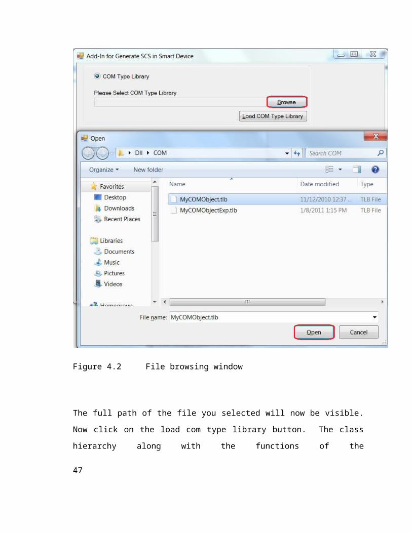
Figure 4.2 File browsing window30

The full path of the file you selected will now be visible. Now click on the load com type
library button. The class hierarchy along with the functions of the selected .tlb/.dll/.exe
file will now be visible in the white box of the window. Check the functions you want to
generate code for and then click on the generate code button to generate the code for the
selected functions.
Figure 4.3 Class and Function Hierarchy
31
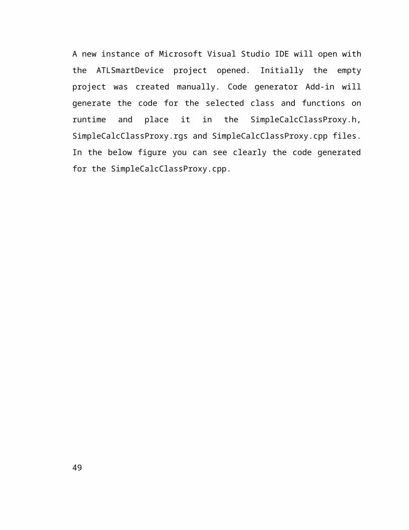
A new instance of Microsoft Visual Studio IDE will open with the ATLSmartDevice
project opened. Initially the empty project was created manually. Code generator Add-in
will generate the code for the selected class and functions on runtime and place it in the
SimpleCalcClassProxy.h, SimpleCalcClassProxy.rgs and SimpleCalcClassProxy.cpp
files. In the below figure you can see clearly the code generated for the
SimpleCalcClassProxy.cpp.
Figure 4.4 ATL Smart Device
32

5. Test Example
Software Testing perform an important role in the Software development. Like traditional
software development, in component based software engineering software testing and
validation is considered as important part of development. This phase of software
development life cycle make sure the success of system and also assessed the output of
system. Is it meet the requirements? The main purposes of testing phase are validation &
verification, estimate system reliability and improve the system quality.
Like other application in this Add-In application I gave a special intention to testing.
There are a lot of testing techniques being used in the software engineering field. I had to
choose such testing techniques which will be efficient and beneficial for my case. So I
selected Microsoft .net debugger for white box testing to ensure that each statement of
my application is executed at least once. While using the .net debugger for white box
testing I created to a specific set of input data which will enable the program control to
execute every statement. This will ensure the correctness of program logic but it cannot
determine the validity of business logic and system specification. In order to verify the
business logic and system specification, and whether all the system specifications are
implemented, I used black box testing. I created different test cases to check that all the
use cases are tested at least once. I wrote test cases covering all the possible scenarios.
After all the logic and specification is tested I moved to test the validity of the generated
output of my application. This is a vital part in the testing of any software. So I started
with a simple example of calculator from MSDN library. Which created a MyComObject
of Com type library for a simple calculator with one class named SimpleCalc, one
interface named ISimpleCalc and four basic functions which are Add(), Subtract(),
Multiply() and Divide()[26].
33
// Used from MSDN library
public ISimpleCalc
{
public:
STDMETHOD(Add)(int iFirstValue, int iSecondValue, int* piResult);
STDMETHOD(Subtract)(int iFirstValue, int iSecondValue, int* piResult);
STDMETHOD(Multiply)(int iFirstValue, int iSecondValue, int* piResult);
STDMETHOD(Divide)(int iFirstValue, int iSecondValue, int* piResult);
};
Now to test the com type library I created a managed client named MyManagedClient.
34

Figure 4.5 Pocket Pc with Calculator Application
Then I used MyComObject with MyManagedClient and recorded the output.
This MyComObject is a simple com component without proxy object and no logging
service is implemented in it. MyManagedClient created an instance of interface
ISimpleCalc and called all the four functions which are Add(), Subtract(), Multiply() and
Divide(). These functions are defined in the CSimpleCalc class. Below is the code for
MyComObject which shows that there is no logging service implemented in it.
35

5.
5.1 Header file// SimpleCalc.h : Declaration of the CSimpleCalc
// Used from MSDN library
#pragma once
#ifdef STANDARDSHELL_UI_MODEL
#include "resource.h"
#endif
#ifdef POCKETPC2003_UI_MODEL
#include "resourceppc.h"
#endif
#ifdef SMARTPHONE2003_UI_MODEL
#include "resourcesp.h"
#endif
#ifdef AYGSHELL_UI_MODEL
#include "resourceayg.h"
#endif
#include "MyCOMObject.h"
// CSimpleCalc
class ATL_NO_VTABLE CSimpleCalc :
public CComObjectRootEx<CComMultiThreadModel>,36

public CComCoClass<CSimpleCalc, &CLSID_SimpleCalc>,
public ISimpleCalc
{
public:
CSimpleCalc()
{
}
#ifndef _CE_DCOM
DECLARE_REGISTRY_RESOURCEID(IDR_SIMPLECALC)
#endif
BEGIN_COM_MAP(CSimpleCalc)
COM_INTERFACE_ENTRY(ISimpleCalc)
END_COM_MAP()
DECLARE_PROTECT_FINAL_CONSTRUCT()
HRESULT FinalConstruct()
{
return S_OK;
37

}
void FinalRelease()
{
}
public:
STDMETHOD(Add)(int iFirstValue, int iSecondValue, int* piResult);
STDMETHOD(Subtract)(int iFirstValue, int iSecondValue, int* piResult);
STDMETHOD(Multiply)(int iFirstValue, int iSecondValue, int* piResult);
STDMETHOD(Divide)(int iFirstValue, int iSecondValue, int* piResult);
};
OBJECT_ENTRY_AUTO(__uuidof(SimpleCalc), CSimpleCalc)
5.2 CPP File// SimpleCalc.cpp : Implementation of CSimpleCalc
// Used from MSDN Library
#include "stdafx.h"
#include "SimpleCalc.h"38
// CSimpleCalc
STDMETHODIMP CSimpleCalc::Add(int iFirstValue, int iSecondValue, int* piResult)
{
// TODO: Add your implementation code here
*piResult = iFirstValue + iSecondValue;
return S_OK;
}
STDMETHODIMP CSimpleCalc::Subtract(int iFirstValue, int iSecondValue, int*
piResult)
{
// TODO: Add your implementation code here
*piResult = iFirstValue - iSecondValue;
return S_OK;
}
STDMETHODIMP CSimpleCalc::Multiply(int iFirstValue, int iSecondValue, int*
piResult)
39

{
// TODO: Add your implementation code here
*piResult = iFirstValue * iSecondValue;
return S_OK;
}
STDMETHODIMP CSimpleCalc::Divide(int iFirstValue, int iSecondValue, int*
piResult)
{
// TODO: Add your implementation code here
if (iSecondValue != 0)
{
*piResult = iFirstValue / iSecondValue;
return S_OK;
}
else
{
*piResult = 0;
return E_FAIL;
}
}
40

In the next step I will extend the functionality of MyComObject and implement the
logging service using the proxy objects through add-in. In above example you can see
clearly that there is no logging service in original component. So here my code generator
comes into play. My code generator will read the com type library file used in the above
mentioned example and generates one proxy .cpp file and one header file for that
proxy .cpp file with names SimpleCalcClassProxy.cpp and SimpleCalcClassProxy.h
respectively, in ATLSmartDevice. There was only one class in this example but if there
were multiple classes in the com type library my code generator can also handle that
scenario. Below are the header and .cpp files generated by the code generator.
5.3 Code Generator Header File//SimpleCalcClassproxy.h
//Generated by my code generator.
#pragma once
#ifdef STANDARDSHELL_UI_MODEL
#include "resource.h"
#endif
#ifdef POCKETPC2003_UI_MODEL
#include "resourceppc.h"
#endif
#ifdef SMARTPHONE2003_UI_MODEL
#include "resourcesp.h"
#endif
#ifdef AYGSHELL_UI_MODEL
41

#include "resourceayg.h"
#endif
#include "ATLSmartDevice.h"
#import"C:\MyCOMObject\MyCOMObject\Windows Mobile 5.0 Pocket PC SDK
(ARMV4I)\Debug\MyCOMObject.tlb" no_namespace raw_interfaces_only
class ATL_NO_VTABLE CSimpleCalcClassproxy:
public CComObjectRootEx<CComMultiThreadModel>,
public CComCoClass<CSimpleCalcClassproxy,&CLSID_SimpleCalcClassproxy>,
public ISimpleCalc
{
public: CSimpleCalcClassproxy() {}
#ifndef _CE_DCOM
DECLARE_REGISTRY_RESOURCEID(IDR_SIMPLECALCCLASSPROXY)
#endif
BEGIN_COM_MAP(CSimpleCalcClassproxy)
COM_INTERFACE_ENTRY(ISimpleCalc)
END_COM_MAP()
DECLARE_PROTECT_FINAL_CONSTRUCT()
HRESULT FinalConstruct()
{
42

HRESULT hr = CoCreateInstance(__uuidof(SimpleCalc), NULL,
CLSCTX_INPROC_SERVER, __uuidof(ISimpleCalc), (void**) &proxy_obj);
return hr;
}
void FinalRelease()
{
proxy_obj->Release();
}
public:
STDMETHOD (Add)(int iFirstValue, int iSecondValue, int* piResult);
STDMETHOD (Subtract)(int iFirstValue, int iSecondValue, int* piResult);
STDMETHOD (Multiply)(int iFirstValue, int iSecondValue, int* piResult);
STDMETHOD (Divide)(int iFirstValue, int iSecondValue, int* piResult);
private:
ISimpleCalc *proxy_obj;
};OBJECT_ENTRY_AUTO(__uuidof(SimpleCalcClassproxy),CSimpleCalcClassproxy)
In the above header file, generated by my code generator, first the com type library is
imported. Then a co-instance of that library is created in the final construct. This co-
instance was later released in the final release method when it is no more needed. This
header file also declares all four methods used in the com type library. A pointer to the
43
Interface of com object ISimpleCalc is also declared in the header file. This was a little
explanation of the header file. Now let’s have a look at .cpp file.
5.4 Code Generated CPP File//SimpleCalcClassproxy.cpp
//Generated by my code generator.
#include "stdafx.h"
#include <stdio.h>
#include "fstream"
#include "SimpleCalcClassproxy.h"
using namespace std;
STDMETHODIMP CSimpleCalcClassproxy :: Add(int iFirstValue, int iSecondValue,
int* piResult)
{
fstream file("\\temp.txt",ios::app);
file<<"Add() operation started..."<<endl;
proxy_obj->Add(iFirstValue, iSecondValue, piResult);
file<<"Add() operation finished..."<<endl;
file.close();
return S_OK;
}
44

STDMETHODIMP CSimpleCalcClassproxy :: Subtract(int iFirstValue, int
iSecondValue, int* piResult)
{
fstream file("\\temp.txt",ios::app);
file<<"Subtract() operation started..."<<endl;
proxy_obj->Subtract(iFirstValue, iSecondValue, piResult);
file<<"Subtract() operation finished..."<<endl;
file.close();
return S_OK;
}
STDMETHODIMP CSimpleCalcClassproxy :: Multiply(int iFirstValue, int
iSecondValue, int* piResult)
{
proxy_obj->Multiply(iFirstValue, iSecondValue, piResult);
return S_OK;
}
STDMETHODIMP CSimpleCalcClassproxy :: Divide(int iFirstValue, int iSecondValue,
int* piResult)
{
proxy_obj->Divide(iFirstValue, iSecondValue, piResult);
return S_OK;
45
}
In the above .cpp file all the four functions used in com object are defined. But here is the
tricky part. Not every function is extended by adding logging functionality into it. The
reason is that only those functions are extended which were selected by the user. So in
above example only Add and Subtract methods have logging service because only they
were selected by the user. Another point which is important to mention here is that there
is no implementation of rest of the functionality provided by that method. The pointer to
the com object, which was declared in the header file, calls the methods of com object so
the original functionality is used as it is. Log file is also shown below.
Figure 4.6 Logging Service on Pocket Pc
46
This log file shows the invocations and completions of Add and Subtract methods. This
shows that my goal is achieved successfully but that’s not all. I also needed to check the
output of the client that whether it is consistent in both cases or not. So I made some
simple calculations using simple com object and also using the extended com object. The
outputs for both were same each time. Hence my generated code was executing correctly.
47

6. Conclusion and Future Work
Conclusion
Component based software development is a widely used software development method.
It takes the object oriented software development to the next level and introduces the
concept of components. Components are used as building blocks for a complete system.
There are a lot of software component models which defines the whole life cycle of a
component, its development, interfacing standards, integrations and deployment. Most
commonly used component models are COM, COM+, DCOM, JavaBeans, Enterprise
JavaBeans, .NET Component model etc. In the field of embedded real time system this
component based software development approach seemed easy and less complex. But
due the resource restrictions in the real time systems these models had a very small scope.
So to resolve this problem a different approach was presented by researchers, which was
to extend the functionality of already available component models. In my thesis I
extended the COM type model for ATL smart device by adding the logging service to it.
I created a visual studio add-in which added the logging service to the COM type library.
It extracts the classes and functions of a COM type library and then generates a proxy
object which adds the logging service for the ATL smart device hence increasing the
functionality of that COM type library. Moreover it does not alter or affect the existent
functionality of the COM type library.
Future Work
My Visual Studio add-in for software component services in ATL smart device only
reads a COM type library and extends its service by adding logging service to it. It can
handle the multi class libraries as well but it is not compatible with .NET assemblies.
Moreover it only provides one service for the ATL smart device which is logging. It does
not provide Synchronization and Execution time measurement services. So in future all
the three services, which are logging, synchronization and execution time measurement,
48
can be provided for the ATL smart device as well as providing the compatibility for .NET
assemblies.
7. References
[1] Keri Akin, “Add-In”
http://whatis.techtarget.com/definition/0,,sid9_gci213748,00.html [Accessed 22
September 2010].
[2] Webopedia, “Add-In” http://www.webopedia.com/TERM/A/add_in.html
[ Accessed 08 October 2010].
[3] Keyvan Nayyeri. “Professional Visual Studio 2008 Extensibility”. (2008)
[4] Ivica Crnkovic, Magnus Larsson “Building reliable Component-based
Software Systems”, Artech House Inc., (2002. pp 3-4).
[5] G. Pour, “Component-Based Software Development Approach: New
Opportunities and Challenges,” Proceedings Technology of Object-Oriented
Languages, 1998. TOOLS 26., pp. 375-383.
[6] Jeffery Cogswell, “Developing Visual Studio .NET and Macros and Add-In”
Wiley Publishing Inc., (2003. pp. 117-118).
[7]. Microsoft “The Component Object Model Specification,” Report Vol. 99,
Microsoft Standards, Redmond, WA: Microsoft, 1996.
[8] Frank Luders, “Specification of Software Component”
http://www.idt.mdh.se/kurser/cdt501/2002/lectures/CBSE-Component
%20Specification.pdf [Accessed 22 December 2010].
[9] MSDN, “Component Object Model”.
http://msdn.microsoft.com/en-us/library/ms694363(v=VS.85).aspx [Accessed 22
Dec 2010]. 49
[10]. MSDN, “The Component Object Model: A Technical Overview”
http://msdn.microsoft.com/enus/library/ms809980.aspx [Accessed 22 Dec 2010].
[11]. Manali Oak, “Understanding Component Object Model - COM Technology.”
http://www.buzzle.com/articles/understanding-component-object-model-com-
technology.html/ [Accessed 22 Dec 2010].
[12] University of Utah flux research group, “The Component Object Model.”
http://www.cs.utah.edu/flux/oskit/html/oskit-wwwch4.html/[Accessed 22 Dec
2010].
[13]. Gopalan Suresh Raj, “The Component Object Model.”
http://gsraj.tripod.com/com/com_ravings.html [Accessed 22 Dec 2010].
[14] MSDN, “Component Object Model.”
http://msdn.microsoft.com/en-us/library/ms694363 (v=VS.85).aspx [Accessed 22
Dec 2010].
[15]. Yandra Siva Kumar, “Disadvantage Of COM”
http://www.dotnetspider.com/forum/28819-Disadvantages-COMcomponents.aspx/
[Accessed 22 Dec 2010].
[16] James Avery, “What is Visual Studio.”
http://oreilly.com/pub/a/windows/2005/08/22/whatisVisualStudio.html
[Accessed 27 December 2010].
[17] Fernando S. Schlindwein, “What is Real Time System?”
http://www.le.ac.uk/eg/fss1/real%20time.htm [Accessed 28 December 2010].
[18] E. Douglas Jensen, “Hard and Soft Real-Time”
http://www.real-time.org/hardandsoftrealtime.htm [Accessed 29 December 2010].
[19] Frank Lüders and Daniel Flemström, “ Software Component Services for
Embedded Real-Time System”. (http://www.mrtc.mdh.se/publications/1055.pdf )50

[20] MSDN, “COM Technical Overview” http://msdn.microsoft.com/enus/library/ff637359(VS.85).aspx
[Accessed 05 Jan 2011].
[21] M.R.V Chaudron, TU Eindhoven & Ivica Crnkovic, “Component Models and
CBSE Processes”
http://www.win.tue.nl/~mchaudro/cbse2007/02_Component_Models_Lifecycle_2
007.pdf [Accessed 08 Jan 2011].
[22] Humberto Cervantes, “The Java Bean Component Model”
http://www.humbertocervantes.net/beansdiscussion.html [Accessed 13 Jan 2011].
[23] Ihor Kuz and Yan Liu., “Extending the Capabilities of Component Models for
Embedded Systems” National ICT Australia.
[24] G. Coulouris, J. Dollimore, T. Kindberg, “Distributed Systems – Concepts and
Design”, fourth edition, Addison-Wesley.
[25] Manzoor Ahmad, “Proxy Objects”
http://www.idt.mdh.se/utbildning/exjobb/files/TR1078.pdf
[Accessed 26 March 2011].
[26] MSDN, “Step by Step: Incorporating COM Objects into Your .NET Compact
Framework 2.0 Application.” http://msdn.microsoft.com/en-us/library/aa446523.aspx
[Accessed 02 Feb 2011].
[27] Hosek, P. and Pop, T. and Bures, T. and Hnetynka, P. and Malohlava, M., “Comparison of Component Frameworks for Real-Time Embedded Systems”, Component-Based Software Engineering: 13th International Symposium, CBSE 2010, Prague, Czech Republic, June 23-25, 2010, Proceedings,Springer,2010, Pages 21.
51