Dedicated to my beloved parents, wife and my...
24
Dedicated to my beloved parents, wife and my daughter…
Transcript of Dedicated to my beloved parents, wife and my...

Dedicated to my beloved parents, wife and my daughter…

“ I hereby declare that I have read through this report entitle “Design and Develop the
Load Detail Calculation Software for Construction Field” and found that it has comply the
partial fulfilment for awarding the degree of Bachelor of Electrical Engineering (Industrial
Power)”
Signature : .......................................................
Supervisor’s Name : ENCIK ANUAR BIN MOHAMED KASSIM
Date : 2 Julai 2012

I declare that this report entitle “Design and Develop the Load Detail Calculation Software
for Construction Field”” is the result of my own research except as cited in the references.
The report has not been accepted for any degree and is not concurrently submitted in
candidature of any other degree.
Signature : ...........................................................
Name : MOHD AZIZI BIN ABD AZIZ
Date : 2 Julai 2012
TABLE OF CONTENTS
CHAPTER TITLE PAGE
ACKNOWLEDGEMENT i
ABSTRACT ii
LIST OF FIGURES iv
LIST OF TABLE v
1 INTRODUCTION 1
1.1 Problem Statement 1
1.2 Objective 1
1.3 Scope 2
1.4 Thesis Outlines 2
2 LITERATURE REVIEW 4
2.1 Introduction 4
2.2 Manual Calculation Method 5
2.3 Excel Calculation Method 8
2.4 Latest Version Calculation Method 10
3 METHODOLOGY 14
3.1 Flow Of Work 14
3.2 Introduction of Visual Basic (VB) 16
3.2.1 What is Visual Basic 16
3.2.2 The Concept of Computer Programming 17
3.2.3 Language Feature of Visual Basic 17
3.2.4 Characteristic of Visual Basic 19
3.3 History of Visual Basic 21
3.4 What Program Can You Create By Visual Basic 21

4 RESULT 23
4.1 Expected Result 23
4.2 Result 24
4.3 Lux Calculation 25
4.4 Total Connected Load (TCL) and Maximum Demand
(MD) 27
5 ANALYSIS and DISCUSSION 30
5.1 Introduction 30
5.2 Lux and Load Detail Calculation Using Manual
Calculation Method 30
5.2.1 Lux Calculation Using Manual Calculation 31
5.2.2 Load Detail Calculation 32
5.3 Lux and Load Detail Calculation Using Excel
Calculation Method 33
5.4 Lux and Load Detail Calculation Using Visual
Basic (VB) Calculation Method 36
5.4.1 Lux Calculation 36
5.4.2 Load Detail Calculation 37
5.5 Simulation To Compare Manual And Software
Calculation 38
6 CONCLUSION 39

i
ACKNOWLEDGMENTS
Assalamualaikum warahmatullahi wabarakatuh and good day,
First and foremost, I thank to Allah the Almighty for blessing me to complete my
overall Project Sarjana Muda. I would like to enlarge my appreciation to my supervisor, Encik
Anuar Bin Mohd Kasim because of the kindness heart to accept me as one of the student under
his supervision. Special thanks also dedicated to his for all comments, idea, and a guideline
begin from the first day I start doing this project until I completed this project.
To my family especially my beloved parents, my wife and my daughter; Abd Aziz Bin
Md Arof and Mariam Bte Ahmad, Noor Azalina Bte Abdul Razak, and Sajidah Kaisyah Bte
Mohd Azizi (8 month). I would like to forward my obliged for their continuous support during
my study period, their patience and benevolence.
I would also like to thank all my friends that always give support, opinion, and advices
for me to complete this report.
Lastly, I would like to thank to everyone who has contributed during my Project
Sarjana Muda. Your kindness and cooperation in completion of my thesis is much appreciated.
Thank you very much

ii
ABSTRACT
In order to calculate load detail while designing for electrical work installation in
construction work, every consultant must calculate it manually. They do not have any software
or any method that can perform calculations automatically. So this project promotes the new
systematic software which can perform the common calculations of load detail. In this project,
there are three objectives to be achieved. First, study and determine the basic load detail
calculation and the JKR specification. Then, design and develop load detail calculation by
using visual basic software. Finally, to evaluate the performance of load detail calculation
through the develop software. This software will be generating by doing programming using
Visual Basic software.

iii
ABSTRAK
Dalam usaha untuk mengira jumlah beban tersambung semasa mereka bentuk untuk
pemasangan kerja elektrik dalam kerja-kerja pembinaan, setiap perunding elektrik mesti
mengira secara manual. Mereka tidak mempunyai apa-apa perisian atau mana-mana kaedah
yang boleh melakukan kiraan secara automatik. Jadi projek ini menggalakkan perisian baru
sistematik yang boleh melakukan pengiraan biasa detail beban. Dalam projek ini, terdapat tiga
objektif yang perlu dicapai. Pertama, mengkaji dan menentukan butir-butir pengiraan beban
asas dan spesifikasi JKR. Kemudian mereka bentuk dan membangunkan beban pengiraan
terperinci dengan menggunakan perisian asas visual. Akhir sekali, untuk menilai prestasi
pengiraan terperinci beban melalui perisian membangunkan. Perisian ini akan menjana dengan
melakukan pengaturcaraan menggunakan perisian Visual Basic.
iv
LIST OF FIGURES
FIGURE TITLE PAGE
2.1.1 Lighting and Power Circuit 5
3.2.1 Flow Diagram of Final Year Project 15
4.2.1 First Form 24
4.3.1 Lux Calculation 25
4.3.2 Room Data 25
4.3.3 Lamp and Luminaries Data 26
4.3.4 Solve 26
4.3.5 Command Button 27
4.4.1 TCL and MD 27
4.4.2 Lamp, Fan and Aircond 28
4.4.3 Sso, Isolator and Other 28
4.4.4 Total of TCL and MD 29
4.4.5 Command Button 29
5.4.1 Lux Calculation 36
5.4.2 Load Detail Calculation 37

v
LIST OF TABLE
TABLE TITLE PAGE
2.3.1 Example of Excel Calculation 11
2.3.2 Example of Excel Calculation 12
5.3.1 Example Calculation Using Excel Calculation Method 34
5.3.2 Example Calculation Using Excel Calculation Method 35
1
CHAPTER 1
INTRODUCTION
1.1 Problem Statement
To have an accurately and efficient method to calculate load detail calculation is
the main factor that been used to design this software. Kindly the old method that been
used by consultant is calculate manually or use Microsoft excel. But it can be improve by
applying visual basic in order to generate the auto calculation. The old method that been
used which is not so efficient in terms of accuracy of results, caused a lot of time and
directly make consultant fee and construction fee become more high then it should.
In addition, human factor can be the one of the major factor can make the
calculation become not so accurate and efficient. Human always do a minor mistake that
should not apply in this calculation. Total connected load (TCL) and maximum demand
(MD) is important thing that can cause a major accident to consumer or during installation.
These calculations can make other calculation such as MCB calculation or cable sizing
calculation wrong. So this calculation must accurate, efficient, save time and easy to use by
consultant.
This project conducted to programme the Visual Basic software to produce
software that can used to calculate the load detail calculation such as total connected load
and maximum demand. The software created will be practically use by consultant. The
availability of this software will increase the speed and accuracy of calculation. As a
whole, this software brings more benefit to the users.
2
1.2 Objectives
The main purpose of this project is to:
(i) Study and determine the basic load detail calculation and the JKR
specification.
(ii) Design and develop load detail calculation by using visual basic software.
(iii) Evaluate the performance of load detail calculation through the developed
software.
1.3 Scope
The scope of this project limited on a number of things. Firstly, the software that
uses to solve the cable sizing process will be programme using Visual Basic software. This
project studies are focus on load detail calculation mainly practice by M&E consultant.
The most important thing is to fulfil the requirement from JKR specification for each
building and application.
1.4 Thesis Outlines
Basically, this report devided into five chapter, which include introduction, theory
and literature review, methodology, expected and preliminary result, discusion and
conclusion.
Chapter 1
Include the project objective, problem statement, scope of work and thesis outlines.

3
Chapter 2
Present the literature review on this project such as manual system to calculate load
detail calculation, using excel to calculate the load detail calculation, and latest version of
calculate for load detail calculation.
Chapter 3
Detail the methodology to achieved the research objective. The methodology will
be summarize in flow chart.
Chapter 4
Present the preliminary result from visual basic software.
Chapter 5
Conclude all the works and studies that had been presented in the previous four
chapters.
4
CHAPTER 2
LITERATURE REVIEW
2.1 Introduction
Load detail calculation is a calculation about the lumen calculation, total connected
load and maximum demand. This calculation method has been used for along time for any
construction and consultant. This calculation is very important calculation because if got
any mistake from this calculation it can make a major disaster. From this calculation also,
the consultant or contractor can choose the size of cable and type of miniature circuit
breaker (mcb) or moulded case circuit breaker (mccb) and residual current circuit breaker
(rccb) that been use for the electrical installation.
Beside that safety and preservation of property also the two important elements to
be consider in the design low voltage system. Safety to personal should not be
compromised and only the safest system can protect our live. Most of the electric system
should protect from short circuit, over current and earth fault. The designer should be
aware and know about how to protect live and equipment from getting damages.
To ensure the safety and long period of the design can sustained, the design should
fulfil all the established codes about safety requirement. The most established codes that
being use is NEC (National Electrical Code), IEE (Regulation for Electrical Installation)
and MS (Malaysian Standard) or BS (British Standard). MS is standard that being use in
Malaysia. Other country has specific standard suitable in that country like Singapore
(CP5). Most of the codes that have being mention usually tell the designer to protected
circuit from various failure of the circuit such as short circuit and overload.
5
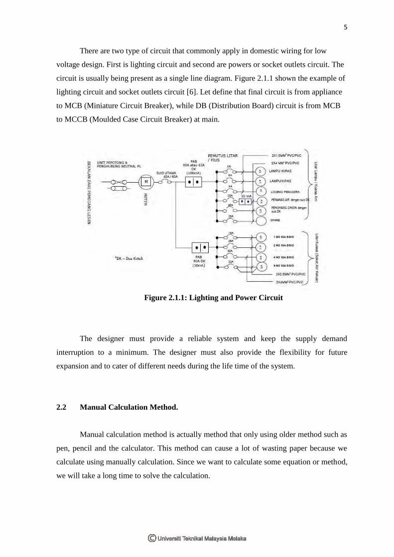
There are two type of circuit that commonly apply in domestic wiring for low
voltage design. First is lighting circuit and second are powers or socket outlets circuit. The
circuit is usually being present as a single line diagram. Figure 2.1.1 shown the example of
lighting circuit and socket outlets circuit [6]. Let define that final circuit is from appliance
to MCB (Miniature Circuit Breaker), while DB (Distribution Board) circuit is from MCB
to MCCB (Moulded Case Circuit Breaker) at main.
Figure 2.1.1: Lighting and Power Circuit
The designer must provide a reliable system and keep the supply demand
interruption to a minimum. The designer must also provide the flexibility for future
expansion and to cater of different needs during the life time of the system.
2.2 Manual Calculation Method.
Manual calculation method is actually method that only using older method such as
pen, pencil and the calculator. This method can cause a lot of wasting paper because we
calculate using manually calculation. Since we want to calculate some equation or method,
we will take a long time to solve the calculation.

6
As we know the load calculation and the lux calculation is very important
calculation for the electrical construction. So for that reason both calculation can’t take
along time to be submit to the person in charge. If the calculation delay the designer will be
fine by the person who in charge the project.
Before we sent the project detail, we actually have to submit to the senior engineer
to be check. When any problem occurs during checking so the submission of the project
will be past back to designer in charge. So when we use the manual calculation method it
will take along time to be settled.
Manual calculation has many disadvantages, one of the disadvantages we have
discussed above. So another disadvantage of manual calculation is cause by human
mistake. Human mistake mean when some one calculates the calculation and the project
depends on the time base the designer will calculate in suspicious way. So the calculation
might be wrong and the starting processes have to do it again.
Human performance can be affected by many factors such as age, state of mind,
physical health, attitude, emotions, propensity for certain common mistakes, errors and
cognitive biases.
Now the calculation is more about the how the lumen calculation and load detail
calculation be calculate using manual calculation. At first stage is lumen calculation.
Lumen measure is a measure Lumens measure "luminous flux". This is a measure of the
total number of packets (or quanta) of light produced by a light source (e.g. a globe or
fluorescent tube). This is the “quantity” of light emitted by the light source. The purpose of
lux is intended to tell that how many lumens designers need given the area you are trying
to illuminate [9]. This is how the lux calculation be calculated using manual calculation
and it depends on related calculation which is calculation of the room index, calculating no
of luminaries and calculating illuminance achieved. The calculation may be made more
quickly and efficiency using well designed format as follows [3]:

7
Calculation room index:
( )
(1.1)
=length x width
Hm x (Length +Width)
Note: Hm = W.P.H x L.M.H
Calculating no of luminaries:
No of Lum =L xW x D. I
Lamp per Luminaire x Lumen Lamp x C. O. U x M. F x D. F.(1.2)
Calculating illuminance achieved:
(1.3)
Illumination archieved in lux
=No. of Lum x Lamps per Lum x Lumens per Lamp x C. O. U x M. F. x D. F
Area
Note:
Symbol Description
Length Length of room dimension
Width Width of room dimension
Area Floor area of room dimension
Lamp per Lum Lamp per Luminaries
Lumen per Lamp Lumen per Lamp
C.O.U Coefficient Of Utilization
8
M.F Maintenance Factor
D.F Design Factor
W.P.H Work Plane Height
L.M.H Luminance Mounting Height
D.I Desired Illuminance
Kr Room Index
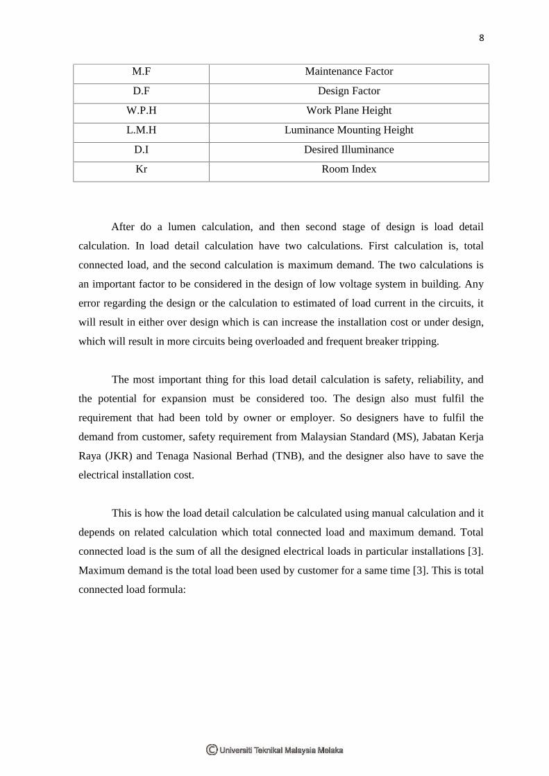
After do a lumen calculation, and then second stage of design is load detail
calculation. In load detail calculation have two calculations. First calculation is, total
connected load, and the second calculation is maximum demand. The two calculations is
an important factor to be considered in the design of low voltage system in building. Any
error regarding the design or the calculation to estimated of load current in the circuits, it
will result in either over design which is can increase the installation cost or under design,
which will result in more circuits being overloaded and frequent breaker tripping.
The most important thing for this load detail calculation is safety, reliability, and
the potential for expansion must be considered too. The design also must fulfil the
requirement that had been told by owner or employer. So designers have to fulfil the
demand from customer, safety requirement from Malaysian Standard (MS), Jabatan Kerja
Raya (JKR) and Tenaga Nasional Berhad (TNB), and the designer also have to save the
electrical installation cost.
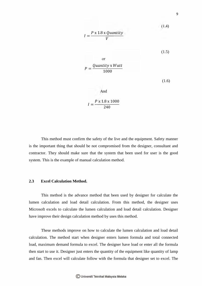
This is how the load detail calculation be calculated using manual calculation and it
depends on related calculation which total connected load and maximum demand. Total
connected load is the sum of all the designed electrical loads in particular installations [3].
Maximum demand is the total load been used by customer for a same time [3]. This is total
connected load formula:
9
(1.4)
=x 1.8 x
(1.5)
or
=x
1000
(1.6)
And
=x 1.8 x 1000
240
This method must confirm the safety of the live and the equipment. Safety manner
is the important thing that should be not compromised from the designer, consultant and
contractor. They should make sure that the system that been used for user is the good
system. This is the example of manual calculation method.
2.3 Excel Calculation Method.
This method is the advance method that been used by designer for calculate the
lumen calculation and load detail calculation. From this method, the designer uses
Microsoft excels to calculate the lumen calculation and load detail calculation. Designer
have improve their design calculation method by uses this method.
These methods improve on how to calculate the lumen calculation and load detail
calculation. The method start when designer enters lumen formula and total connected
load, maximum demand formula to excel. The designer have load or enter all the formula
then start to use it. Designer just enters the quantity of the equipment like quantity of lamp
and fan. Then excel will calculate follow with the formula that designer set to excel. The

10
designer gets the result after that. So they use the final result to decide the protective
device that will be use to the system.
This method can reduce the error that which doing by human. Because designer just
enter the quantity and excel will do automatically the calculation. Designers don’t have to
calculate with calculator. It will make them happy to design everything and put the entire
equipment together.
This method also has a disadvantages. Example of disadvantage which doing by
junior designer is they like to copy what their senior just doing. They just copy excel and
enter the quantity of the equipment which is design by them. They never check the formula
from excel. Sometime senior designer enter the wrong formula but they recognise it at the
site. Then they just do a correction at site and don’t do it at the formula.
When junior designer use excels, then get a trouble with that thing. They don’t
know how to solve that thing. Then they will damage the consultant name. By the way if
the consultant name getting worse, so the consultant doesn’t get any project again. This can
affect more trouble to consultant and consumer.
This method also not so accurate and efficient but its still more accurate and
efficient compare to manual calculation. It decreases the mistake from human and does a
calculation efficiently. Time to design will be short and faster compare to manual
calculation. The example of this calculation show in Table 2.3.1 and Table 2.3.2 below.

11
Dewan 1 Malaysia
ILLUMINATION CALCULATION (option 1) 250W
Room Dimension Area
Design Lux Maintenance factor (mf)
Ceiling ht
Mounting height above desk level (Ht = ceiling ht - desk ht(say 0.85))
Room Index = (L*W)/(Ht*(L+W))
Coefficient of Utilisation (uf)-Refer Catalogue
Type of light fitting Lumen No. of fluo. Tube
Calculation of no. of light fitting = (lux)(Area)/[(mf)(uf)(lumen)]
Proposed no. of light fitting
Calculated Lux
L(m) W(m)
1x250W Pyramid 27500
1x400W Pyramid 47500
Dewan 1 malaysia
Dewan (12court) 50.00 33 1650.00 1000 0.8 12 11.15 1.78 0.52 1x250W Pyramid 27500 1 144 144 998
Dewan (1court) 16.00 8 128.00 1000 0.8 12 11.15 0.48 0.52 1x250W Pyramid 27500 1 11 11 983
Dewan (12court) 50.00 33 1650.00 2000 0.8 12 11.15 1.78 0.52 1x250W Pyramid 27500 1 288 288 1997
Dewan (1court) 16.00 8 128.00 2000 0.8 12 11.15 0.48 0.52 1x250W Pyramid 27500 1 22 22 1966
Dewan stage 24.00 8 192.00 300 0.8 10 9.15 0.66 0.52 1x400W Metal Halide 38000 1 4 4 329

12
Cct Description Unit Qty CL DF MD
load (kW) (kW)
(kW)
2x36W Fluo Ftg 0.084 0.00 0.8 0.00
1x36W Fluo Ftg 0.042 0.00 0.8 0.00
2x18W Fluo Ftg 0.048 0.00 0.8 0.00
1x18W Fluo Ftg 0.024 0.00 0.8 0.00
2x11W Down Light 0.034 0.00 0.8 0.00
1x11W Down Light 0.017 0.00 0.8 0.00
2x11W Wall Light 0.034 0.00 0.8 0.00
1x11W Wall Light 0.017 0.00 0.8 0.00
Spotlight 0.200 0.00 0.8 0.00
250W pyramid 0.250 145 36.25 0.8 29.00
400W Metal Halide 0.425 0.00 0.8 0.00
Ceiling Fan 0.080 0.00 0.8 0.00
Wall Fan 0.080 0.00 0.8 0.00
Insect Killer 0.350 0.00 0.8 0.00
Exhaust Fan 0.080 8 0.64 0.8 0.51
Emergency Light
Keluar Sign
Aircond Point (1hp) 0.75 0.00 0.6 0.00
Aircond Point (1.5hp) 1.12 0.00 0.6 0.00
Aircond Point (2hp) 1.49 0.00 0.6 0.00
Aircond Point (2.5hp) 1.87 0.00 0.6 0.00
Aircond Point (3hp) 2.24 20 44.76 0.6 26.86
Spare
Cct Description Unit Qty CL DF MD
load (kW) (kW)
(kW)
Water Heater 3.00 0.00 0.5 0.00
13A S/S/O (Single) 0.350 0.00 0.5 0.00
13A S/S/O (Double) 0.700 0.00 0.5 0.00
Isolator 30A 5.000 0.00 0.5 0.00
Isolator 60A 10.000 0.00 0.5 0.00
Spare
Total 81.65 56.37

13
2.4 Latest Version Calculation Method Using Visual Basic (VB).
This latest version of calculation use software. From all the software at the market,
then visual basic is the suitable software compare to other software. The best thing about
this software is this software is good for being front page or for interface. Visual Basic is
particularly strong at creating interface for databases.
This software is user friendly and easy to use by most of the people. The language
is very simple, particularly as to the executable code. Visual Basic not only a language but
primarily an integrated, interactive development environment (‘IDE’). Visual Basic is
particularly easy to develop graphical user interfaces and to connect them to handler
functions provided by the application.
After this software is ready made, then designer just have to enter the quantity of
the item used. Designer also has to enter the horse power if the item used is air-conditioned
or motor. If designers design motor, they have to check the motor rating to enter in visual
basic system. When all the item had enter, stay for a while, visual basic will tell designer
about the total connected load and maximum demand.
14
CHAPTER 3
METHODOLOGY
3.1 Flow of Works
Figure 3.2.1 showing the flow of work for this final project. Firstly, study on load
detail calculation. Attach with consultant in order to study load detail calculation. There is
a problem in manual calculation. Then, do the literature review and some research
regarding load detail calculation. After that, check any suitable software to overcome this
problem. Visual basic (VB) is the suitable software to overcome the limitation in manual
calculation. Learn how to use visual basic, so that the programming process in Visual
Basic will be easy. After that, design the load detail calculation software use visual basic
until it can be running successfully. Finally, compare the result obtained from both manual
and software calculation. In addition, doing calculation using the programmed software
consumed less times compare to manual calculation.