Decision document - REFIRE
35
Environmental Protection Act 1986 Page 1 of 35 Decision Document: W5584/2014/1 File Number: 2013/004020 IRLB_TI0669 v2.4 Decision Document Environmental Protection Act 1986, Part V Proponent: Bechtel (Western Australia) Pty Ltd Works Approval: W5584/2014/1 Registered office: Level 6, AMP Building 140 St Georges Tce PERTH WA 6000 ACN: 147 531 226 Premises address: LNG and Domgas Plant Lot 238 on Plan 195206 and Lots 567 and 569 on Plan 71345 within the coordinates 292494E, 7600062N; 293013E, 7600130N; 293007E, 7600605N; 293396E, 7600506N; 293309E, 7600195N; 293254E, 7600190N; 293179E, 7599911N; 293888E, 7599721N; 293989E, 7600101N; 293636E, 7600195N; 294180E, 7600201N; 294272E, 7599965N; 294128E, 7599424N; 293001E, 7598067N; 292271E, 7598066N; 292343E, 7598337N and 292343E, 7599454N. TALANDJI WA 6710 Issue date: Wednesday, 23 April 2014 Commencement date: Monday, 28 April 2014 Expiry date: Saturday, 27 April 2019 Decision Based on the assessment detailed in this document the Department of Environment Regulation (DER) has decided to issue a works approval. DER considers that in reaching this decision, it has taken into account all relevant considerations. Decision Document prepared by: Fiona Esszig Regional Environmental Officer Decision Document authorised by: Alana Kidd Regional Leader
Transcript of Decision document - REFIRE

Environmental Protection Act 1986 Page 1 of 35 Decision Document: W5584/2014/1 File Number: 2013/004020 IRLB_TI0669 v2.4
Decision Document
Environmental Protection Act 1986, Part V
Proponent: Bechtel (Western Australia) Pty Ltd
Works Approval: W5584/2014/1
Registered office: Level 6, AMP Building
140 St Georges Tce PERTH WA 6000
ACN: 147 531 226 Premises address: LNG and Domgas Plant
Lot 238 on Plan 195206 and Lots 567 and 569 on Plan 71345 within the coordinates 292494E, 7600062N; 293013E, 7600130N; 293007E, 7600605N; 293396E, 7600506N; 293309E, 7600195N; 293254E, 7600190N; 293179E, 7599911N; 293888E, 7599721N; 293989E, 7600101N; 293636E, 7600195N; 294180E, 7600201N; 294272E, 7599965N; 294128E, 7599424N; 293001E, 7598067N; 292271E, 7598066N; 292343E, 7598337N and 292343E, 7599454N. TALANDJI WA 6710
Issue date: Wednesday, 23 April 2014 Commencement date: Monday, 28 April 2014 Expiry date: Saturday, 27 April 2019 Decision Based on the assessment detailed in this document the Department of Environment Regulation (DER) has decided to issue a works approval. DER considers that in reaching this decision, it has taken into account all relevant considerations. Decision Document prepared by: Fiona Esszig
Regional Environmental Officer Decision Document authorised by: Alana Kidd
Regional Leader

Environmental Protection Act 1986 Page 2 of 35 Decision Document: W5584/2014/1 File Number: 2013/004020 IRLB_TI0669 v2.4
Contents Decision Document 1 Contents 2 1 Purpose of this Document 2 2 Administrative summary 3 3 Executive summary of proposal 5 4 Decision table 10 5 Advertisement and consultation table 17 6 Emissions and discharges risk assessment framework 18 Appendix A 19 Appendix B 21 Appendix C 30 Appendix D 34
1 Purpose of this Document This decision document explains how DER has assessed and determined the application for a works approval or licence, and provides a record of DER’s decision-making process and how relevant factors have been taken into account. Stakeholders should note that this document is limited to DER’s assessment and decision making under Part V of the Environmental Protection Act 1986. Other approvals may be required for the proposal, and it is the proponent’s responsibility to ensure they have all relevant approvals for their Premises. Works approval and licence conditions DER has three types of conditions that may be imposed on works approvals and licences. They are as follows; Standard conditions (SC) DER has standard conditions that are imposed on all works approvals and licences regardless of the activities undertaken on the Premises and the information provided in the application. These are included as the following conditions on works approvals and licences:
Works approval conditions: 1.1.1-1.1.4, 1.2.1, 1.2.2, 5.1.1 and 5.1.2. Licence conditions: 1.1.1-1.1.4, 1.2.1-1.2.4, 5.1.1-5.1.4 and 5.2.1.
For such conditions, justification within the Decision Document is not provided. Optional standard conditions (OSC) In the interests of regulatory consistency DER has a set of optional standard conditions that can be imposed on works approvals and licences. DER will include optional standard conditions as necessary, and are likely to constitute the majority of conditions in any licence. The inclusion of any optional standard conditions is justified in Section 4 of this document. Non standard conditions (NSC) Where the proposed activities require conditions outside the standard conditions suite DER will impose one or more non-standard conditions. These include both premises and sector specific conditions, and are likely to occur within few licences. Where used, justification for the application of these conditions will be included in Section 4.

Environmental Protection Act 1986 Page 3 of 35 Decision Document: W5584/2014/1 File Number: 2013/004020 IRLB_TI0669 v2.4
2 Administrative summary
Administrative details
Application type
Works Approval ☒
New Licence ☐ Licence amendment ☐ Works Approval amendment ☐
Activities that cause the premises to become prescribed premises
Category number(s)
Assessed design capacity
10
8.9 million tonnes of liquefied natural gas (LNG) per annum
200 terajoules (TJ) of domestic gas
4,494,000 cubic metres (m3) of condensate per annum
34
52 184 megawatts (MW) (including 12 MW of backup power)
Application verified
Application fee paid
Date: 10 January 2014
Date: 20 January 2014
Works Approval has been complied with
Compliance Certificate received
Yes ☐ No ☐ N/A ☒
Yes ☐ No ☐ N/A ☒
Commercial-in-confidence claim Yes ☐ No ☒
Commercial-in-confidence claim outcome N/A.
Is the proposal a Major Resource Project? Yes ☒ No ☐
Was the proposal referred to the Environmental Protection Authority (EPA) under Part IV of the Environmental Protection Act 1986?
Yes ☒ No ☐
Referral decision No:
Managed under Part V ☐
Assessed under Part IV ☒
Is the proposal subject to Ministerial Conditions?
Yes ☒ No ☐
Ministerial statement No: 873
EPA Report No: 1404
Ministerial statement amendments 904 (Report 1440), 922 (Report 1462) and 931 (Report 1464)
Does the proposal involve a discharge of waste into a designated area (as defined in section 57 of the Environmental Protection Act 1986)?
Yes ☐ No ☒
Department of Water consulted Yes ☐ No ☒
Is the Premises within an Environmental Protection Policy (EPP) Area Yes ☐ No ☒

Environmental Protection Act 1986 Page 4 of 35 Decision Document: W5584/2014/1 File Number: 2013/004020 IRLB_TI0669 v2.4
If Yes include details of which EPP(s) here.
Is the Premises subject to any EPP requirements? Yes ☐ No ☒
If Yes, include details here, eg Site is subject to SO2 requirements of Kwinana EPP.

Environmental Protection Act 1986 Page 5 of 35 Decision Document: W5584/2014/1 File Number: 2013/004020 IRLB_TI0669 v2.4
3 Executive summary of proposal Bechtel (Western Australia) Pty Ltd is developing the Wheatstone Project Liquefied Natural Gas (LNG) and Domestic Gas (Domgas) Plant on behalf of Chevron Australia Pty Ltd (Chevron). Chevron has engaged Bechtel as the engineering, procurement and construction contractor to deliver the LNG Plant and associated facilities. This works approval is for the construction of:
• The LNG Plant including two LNG processing trains;
• Domestic gas (Domgas) plant consisting of a single train;
• Utilities including fuel gas and recycle gas turbine, power generation, heating media systems, flares and vents, diesel storage and refrigerant storage;
• Stormwater drainage; and
• Other supporting facilities such as fire and gas protection, air and water systems, turbine inlet air humidification and nitrogen system.
To accommodate the longer construction timeframe, the LNG and condensate storage tanks were assessed and approved under a separate works approval (W5480/2013/1). The Wheatstone Project is located approximately 12 kilometres (km) south west of Onslow, in the Pilbara region of Western Australia. The nearest sensitive receptors to the project include:
• Onslow (12 km north east);
• Onslow Solar Salt Project operated by Onslow Salt Pty Ltd (3 km east);
• Urala Station (20 km);
• Macedon Gas Project and accommodation village (2 km); and
• Ashburton North Village, which is the accommodation village operated by Bechtel (8 km south east).
LNG plant The LNG plant will consist of two processing trains and will be capable of producing 8.9 million tonnes of LNG per annum. The main process will include:
Inlet gas conditioning and condensate stabilisation: Feed gas arrives onsite and is directed to the slugcatcher where it is separated into three phases (gas, condensate and wastewater). Condensate is stabilised in the condensate stabiliser system, which strips off light-end hydrocarbons to meet condensate vapour pressure specifications before sending the product to the condensate tanks for storage. Stripped gas is compressed and transferred to the main gas feed line to the LNG and Domgas trains for processing. Wastewater is routed to the wastewater treatment system for treatment and disposal. Acid gas removal units (AGRU): The AGRU removes acid gas (carbon dioxide (CO2) and hydrogen sulphide (H2S)) using conventional activated methaldiethanolamine (aMDEA) technology. Some volatile organic compounds including benzene, toluene, ethylbenzene and xylene (BTEX) from the process gas are also absorbed. The stripped gas contains 93% CO2, water and trace amounts of BTEX and H2S, which will be disposed of via the Acid Gas Thermal Oxidiser (AGTO). One AGTO is installed on each train and will oxidise the hydrocarbons or sulphur compounds to CO2, oxides of sulphur (SOx) and water. The aMDEA solvent is regenerated via a closed loop system.

Environmental Protection Act 1986 Page 6 of 35 Decision Document: W5584/2014/1 File Number: 2013/004020 IRLB_TI0669 v2.4
Dehydration: Dehydration units (one located on each train) will remove water from the feed gas using a molecular sieve to prevent water freezing in the cryogenic units. Mercury removal: Mercury is removed via a mercury removal unit equipped with mercury absorbents. Each train will be fitted with a mercury removal unit and is essential to prevent corrosion of the brazed aluminium exchangers in the liquefaction system. Heavy hydrocarbon removal and fractionations: Heavy hydrocarbons remaining in the stream are separated and fractionated to prevent freezing in the low temperature liquefaction section. These heavy components are recovered as natural gas liquids or condensate and are blended with stabilised condensate from the inlet facilities and stored in condensate storage tanks. Liquefaction and refrigerant compression, including nitrogen rejection unit (NRU): The liquefaction system progressively cools conditioned gas to -160 degrees Celsius (°C) using a cascade of successive refrigeration steps to liquefy gas to LNG. Three refrigerants are used; propane, ethylene and methane, in separate circulation loops. Refrigerant compressors in each train are powered by LM6000PF aero derivative gas turbine drivers (six per train). As conditioned gas passes through a series of heat exchangers, it gives up heat to the successive refrigerants and cools. Cooled gas is then flashed (allows to expand into a separator or drum) to atmospheric pressure, cooling it further. The cryogenic NRU system is used to remove excess nitrogen (N2) to meet LNG and fuel gas specifications. N2 is cryogenically separated and concentrated in the NRU via a series of fractionation columns. Concentrated N2, with trace amounts of methane, is vented to atmosphere. Resulting LNG will be pumped to the cooled and insulated LNG storage tanks and stored at atmospheric pressure at -160°C ready for shipment.
Figure 1 shows a diagrammatic representation of the LNG process.
Figure 1: LNG process.
Environmental Protection Act 1986 Page 7 of 35 Decision Document: W5584/2014/1 File Number: 2013/004020 IRLB_TI0669 v2.4
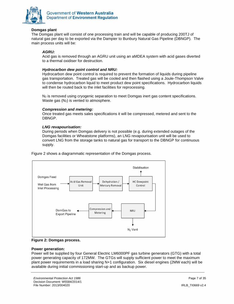
Domgas plant The Domgas plant will consist of one processing train and will be capable of producing 200TJ of natural gas per day to be exported via the Dampier to Bunbury Natural Gas Pipeline (DBNGP). The main process units will be:
AGRU: Acid gas is removed through an AGRU unit using an aMDEA system with acid gases diverted to a thermal oxidiser for destruction. Hydrocarbon dew point control and NRU: Hydrocarbon dew point control is required to prevent the formation of liquids during pipeline gas transportation. Treated gas will be cooled and then flashed using a Joule-Thompson Valve to condense hydrocarbon liquid to meet product dew point specifications. Hydrocarbon liquids will then be routed back to the inlet facilities for reprocessing. N2 is removed using cryogenic separation to meet Domgas inert gas content specifications. Waste gas (N2) is vented to atmosphere. Compression and metering: Once treated gas meets sales specifications it will be compressed, metered and sent to the DBNGP. LNG revapourisation: During periods when Domgas delivery is not possible (e.g. during extended outages of the Domgas facilities or Wheatstone platforms), an LNG revapourisation unit will be used to convert LNG from the storage tanks to natural gas for transport to the DBNGP for continuous supply.
Figure 2 shows a diagrammatic representation of the Domgas process.
Figure 2: Domgas process. Power generation: Power will be supplied by four General Electric LM6000PF gas turbine generators (GTG) with a total power generating capacity of 172MW. The GTGs will supply sufficient power to meet the maximum plant power requirements in a load sharing N+1 configuration. Six diesel engines (2MW each) will be available during initial commissioning start-up and as backup power.

Environmental Protection Act 1986 Page 8 of 35 Decision Document: W5584/2014/1 File Number: 2013/004020 IRLB_TI0669 v2.4
Fuel gas and recycle gas systems: The fuel gas system will provide fuel gas to the plant and consists of:
• High pressure (HP) fuel gas section, supplying fuel to the Gas Turbine Drivers and GTGs; and
• Low pressure (LP) fuel gas section providing fuel gas to the flare pilots and purges, AGTO and Domgas plant regeneration gas heaters.
Fuel gas is normally supplied by the methane compressor, however, back up fuel gas can be supplied from the outlet of the dehydration unit and inlet facilities. Heating medium system: Waste heat recovery units (WHRU) will be installed in exhaust ducts on each of the refrigeration gas turbines and will provide all of the LNG plant’s process heating requirements. A closed loop, hot oil heating medium will be used to transport heat from the WHRUs through the plant to condensate stabilisation facilities, AGRU regeneration and fractionation reboiler. A small gas fired hot oil start-up heater common to both the LNG trains will only be used during start-up operations when the refrigerant gas turbine drivers are not operating. Pressure relief, liquids disposal, flare and vent systems: A pressure relief and liquids disposal system, consisting of both wet and dry flare systems, will be designed to collect and dispose of waste hydrocarbon vapour and recover liquids produced during activities such as start-up and shutdown, or during unexpected events such as trips or equipment breakdown. The flare system will consist of:
• LP system with three flare risers (wet, dry and spare);
• HP system with three flare risers (wet, dry and spare); and
• Marine flare for handling vapour from the LNG storage tanks and excess boil off gas (BOG) generated during LNG ship loading.
The wet gas relief and flare system handles gases that contain hydrocarbons with water or water vapour, and typically handles gases from ‘warm’ plant systems (i.e. prior to cryogenic cooling). The dry gas relief and flare system handles cold gas free of water vapour. Both systems operate independently of each other and will consist of a large collection header and liquid knockout drum. A spare knockout drum and flare stack are provided to serve as a common backup system to both the wet and dry flare systems. The marine flare system will support the safe loading of LNG carriers. It will be designed to allow the cool-down and displacement of inert gases from LNG carriers which arrive at the loading berth in a warm condition or which are returning to service after dry dock inspection. Since no liquid condensation is possible in this flare header, liquid separation/collection/disposal facilities will not be provided in this system. Commissioning The LNG plant will be constructed and commissioned in various stages over approximately a four year period. Train 1 will be constructed initially, followed by the Domgas Plant and Train 2. Commissioning phases are shown in Table 1. Following wet commissioning, each stage will be progressively handed over to Chevron who will assume operational control and continue to commission the plant until a steady operational state is achieved. It is anticipated that steady state operations may take up to two years to achieve. Handover will occur once plant is operating safely and reliably and it is at this point that a licence is required.

Environmental Protection Act 1986 Page 9 of 35 Decision Document: W5584/2014/1 File Number: 2013/004020 IRLB_TI0669 v2.4
Table 1: Commissioning phases
Description of Activity
Construction Phase
Hydrostatic testing
Minimal hydrostatic testing will occur, however, where it is required, hydrostatic testing of piping systems will utilise fresh water low in suspended solids.
Pre-commissioning
Individual component integrity and function testing and may include activities such as flushing, chemical cleaning, calibration and testing of instruments and valve tightness.
Commissioning Phase
Commissioning System integrity and function testing and is the process of initial operation and testing that verifies that all systems, plant, machinery, etc. are capable of performing to the maximum extent possible. Commissioning includes the introduction of feed gas and other process fluids required to bring the plant to a fully operational state, and includes performance testing to verify the system operational parameters against the design.
Wet commissioning
Wet commissioning includes the introduction of feed gas. Bechtel will then handover each train following the loading of one shipment of LNG.
Turnover At operational acceptance, jurisdictional control of relevant Plant systems is transferred from the Works Approval Holder to the Licensee, which is known as Turnover of Care, Custody and Control (TCCC). Turnover of the project contains three separate TCCC for Train 1 (including common facilities), Train 2, and Domgas plant. Turnovers occur upon successful completion and acceptance of mechanical completion, performance testing, and a complete tanker loading of the LNG product when operational control is transferred to the licensee.
Operation Phase
Upon completion of commissioning, and at the point of turnover, an operational Licence is required for operating the plant. An emissions verification report will be required to be submitted as part of a Licence condition to verify emissions at steady state.

Environmental Protection Act 1986 Page 10 of 35 Decision Document: W5584/2014/1 File Number: 2013/004020 IRLB_TI0669 v2.4
4 Decision table All applications are assessed under the Environmental Protection Act 1986, the Environmental Protection Regulations 1987, DER’s Policy Statement - Limits and targets for prescribed premises (2006) and the risk matrix attached to this decision document in Section 6. Where other references have been used in making the decision they are detailed in the decision table.
DECISION TABLE
Works Approval / Licence section
Condition number
W = Works Approval L= Licence
OSC or NSC
Justification (including risk description & decision methodology where relevant)
Reference documents
General conditions
W1.1 - W1.3 L1.1 - 1.3
N/A Construction and operation Emission Significance – 1 Socio-political context – Low Risk Assessment – E – No regulation, other management measures A condition has been included that allows commissioning each train of the LNG for a period not exceeding the timescale to be specified in a commissioning plan and not exceeding a period of 18months for Train 1 and 12 months for Train 2. A condition has been included that allows commissioning the Domgas train for a period for a period not exceeding the timescale to be specified in commissioning and not exceeding a period of 12 months. Details of DER’s assessment and decision making are included in Appendix A.
Application supporting documentation.
Emissions general
L2.1.1 OSC Descriptive limits will be set through conditions 2.1.1 of the licence and, therefore, an OSC regarding recording and investigation of exceedances of limits or targets will be included.
N/A.

Environmental Protection Act 1986 Page 11 of 35 Decision Document: W5584/2014/1 File Number: 2013/004020 IRLB_TI0669 v2.4
DECISION TABLE
Works Approval / Licence section
Condition number
W = Works Approval L= Licence
OSC or NSC
Justification (including risk description & decision methodology where relevant)
Reference documents
Point source emissions to air including monitoring
W2 and W3 L2.2 and L3.2
OSC Construction and operation Emission Significance – 3 Socio-political context – Low Risk Assessment – C – Licence conditions, setting limits/targets Details of DER’s assessment and decision making are included in Appendix B.
Environmental Protection (Unauthorised Discharges) Regulations 2004. Application supporting documentation. Ambient Air Assessment Criteria, National Environmental Protection Measure (Ambient Air Quality). MS873. Australian Standard AS4323.1 Stationary Source Emissions Method 1: Selection of sampling positions.
Point source emissions to surface water including monitoring
W2.3 L2.3 and L3.3
N/A Construction and operation Emission Significance – 1 Socio-political context – No interest or concern Risk Assessment – E – No regulation, other management mechanisms Details of DER’s assessment and decision making are included in Appendix C.
Application supporting documentation. MS873.

Environmental Protection Act 1986 Page 12 of 35 Decision Document: W5584/2014/1 File Number: 2013/004020 IRLB_TI0669 v2.4
DECISION TABLE
Works Approval / Licence section
Condition number
W = Works Approval L= Licence
OSC or NSC
Justification (including risk description & decision methodology where relevant)
Reference documents
Point source emissions to groundwater including monitoring
W2 and W3 L2.4 and L3.4
N/A Construction and operation Emission Significance – 1 Socio-political context – No interest or concern Risk Assessment – E – No regulation, other management mechanisms Groundwater is situated approximately 0.5 m below Australia Height Datum (AHD), however, it varies above and below this across the project area. The project area is generally a groundwater discharge zone (i.e. groundwater is generally pressurised and rises to the surface). There are no point source emissions to groundwater associated with the proposal and no specified conditions relating to the point source emissions to groundwater are required on the licence or works approval.
Application supporting documentation. Environmental Protection (Unauthorised Discharges) Regulations 2004.
Emissions to land including monitoring
W2 and W3 L2.5 and L3.5
OSC Construction and operation Emission Significance – 1 Socio-political context – No interest or concern Risk Assessment – E – No regulation, other management mechanisms Details of DER’s assessment and decision making are included in Appendix C.
Application supporting documentation. Environmental Protection (Unauthorised Discharges) Regulations 2004. MS873.

Environmental Protection Act 1986 Page 13 of 35 Decision Document: W5584/2014/1 File Number: 2013/004020 IRLB_TI0669 v2.4
DECISION TABLE
Works Approval / Licence section
Condition number
W = Works Approval L= Licence
OSC or NSC
Justification (including risk description & decision methodology where relevant)
Reference documents
Fugitive emissions
W2 L2.6
OSC Construction and operation Emission Significance – 2 Socio-political context – No interest or concern Risk Assessment – E – No regulation, other management mechanisms Construction activities will be predominantly during daylight hours, however, some night-time works will be undertaken. Lighting impacts during construction are not expected to be significant. Commissioning and operation of the LNG and Domgas plant will occur 24 hours a day. Lighting will be installed to ensure that relevant safety requirements are met. Light emissions were modelled and results indicated that at a distance of 400 m, emissions will not exceed that of a clear moonlit night. Results also indicated that no turtle nesting beaches in the vicinity of the project area (nearest nesting beach is 4 km away) would receive direct illumination from routine lighting. Lighting impacts will be managed and monitored in accordance with the Conservation Significant Marine Fauna Interaction Management Plan required under MS873. Measures in place to minimise and manage lighting impacts include:
• Lights will be controlled by photovoltaic cells that automatically switch on or off depending on ambient light conditions;
• No decorative lighting will be installed;
• Metal halides, mercury vapour fixtures, white or ultraviolet lights will not be used;
• Lighting will be focused downward to reduce overhead glow; and
• Jetty lighting will be focused onto work surface.
MS873. Conservation Significant Marine Fauna Interaction Management Plan.

Environmental Protection Act 1986 Page 14 of 35 Decision Document: W5584/2014/1 File Number: 2013/004020 IRLB_TI0669 v2.4
DECISION TABLE
Works Approval / Licence section
Condition number
W = Works Approval L= Licence
OSC or NSC
Justification (including risk description & decision methodology where relevant)
Reference documents
Odour
W2 L2.7.1
OSC Construction and operation Emission Significance – 1 Socio-political context – No interest or concern Risk Assessment – E – No regulation, other management mechanisms Odour emissions may be generated during the commissioning and operation of the LNG and Domgas plants via leaks or spills of hydrocarbon materials. The nearest sensitive receptor is the Macedon accommodation village, which is located 2 km away, and as such impacts from odour will not be significant. A Leak Detection and Repair (LDAR) program will be developed to monitor for fugitive emissions of BTEX and VOCs to manage potential odours. No specified conditions relating to odour are required on the works approval. OSC 2.7.1 will be included on the licence to ensure that odour does not cause offsite impacts.
Application supporting documentation. Environmental Protection (Unauthorised Discharges) Regulations 2004.
Noise
W2 L2.8
OSC Construction and operation Emission Significance – 3 Socio-political context – Low Risk Assessment – C – Licence conditions, setting targets Details of DER’s assessment and decision making are included in Appendix D.
Environmental Protection (Noise) Regulations 1997. Draft Guidance No. 8: Guidance for Environmental Noise.
Monitoring general
W3 L3
OSC SC will be included on the licence requiring monitoring to be conducted in accordance with relevant Australian Standards, and companies and laboratories with National Association of Testing Authorities (NATA) accreditation.
Monitoring of inputs and outputs
W3 L3
N/A No conditions relating to monitoring of inputs or outputs are required on the works approval.

Environmental Protection Act 1986 Page 15 of 35 Decision Document: W5584/2014/1 File Number: 2013/004020 IRLB_TI0669 v2.4
DECISION TABLE
Works Approval / Licence section
Condition number
W = Works Approval L= Licence
OSC or NSC
Justification (including risk description & decision methodology where relevant)
Reference documents
Process monitoring
W3 L3
N/A No conditions relating to process monitoring are required on the works approval.
Ambient quality monitoring
W3 and W4.1.1 L3.8.1
OSC Groundwater monitoring will occur during construction and commissioning in accordance with the Construction Groundwater Monitoring Procedure. An operational groundwater monitoring program will be developed prior to the operation of the facility. OSC 3.8.1 will be included on the licence relating monitoring of groundwater quality as a means of detecting contamination. Details of the ambient air quality monitoring program are provided in Appendix B.
Application supporting documentation. Construction Groundwater Monitoring Procedure.
Meteorological monitoring
W3 W3.9
OSC Weather station equipment is proposed to be added to the existing and proposed ambient air quality monitoring stations. Installation is proposed to occur over Q2/Q3 2014. The weather stations are proposed to be installed at two locations (Onslow Town and one of the proposed site based locations). The parameters to be monitored for Onslow Town station include ambient temperature, wind speed, wind direction, rainfall, and relative humidity. The parameters to be monitored for the site based location include ambient and differential temperature, wind speed, wind direction, rainfall, solar radiation and relative humidity. OCS 3.9 will be included on the licence relating to meteorological monitoring.
Application supporting documentation.
Improvements
W4.1.1 L4
OSC The works approval includes OSC 4.1.1 requiring the submission of a pre-commissioning and hydrostatic testing plan, and commissioning plan. The plans are required to be submitted to the Director prior to the associated works commencing, and are to include details of specific activities and measures in place to manage and monitor emissions and discharges from the premises.
Environmental Protection Act 1986 Page 16 of 35 Decision Document: W5584/2014/1 File Number: 2013/004020 IRLB_TI0669 v2.4
DECISION TABLE
Works Approval / Licence section
Condition number
W = Works Approval L= Licence
OSC or NSC
Justification (including risk description & decision methodology where relevant)
Reference documents
Information
W5 L5.1 and W5.2
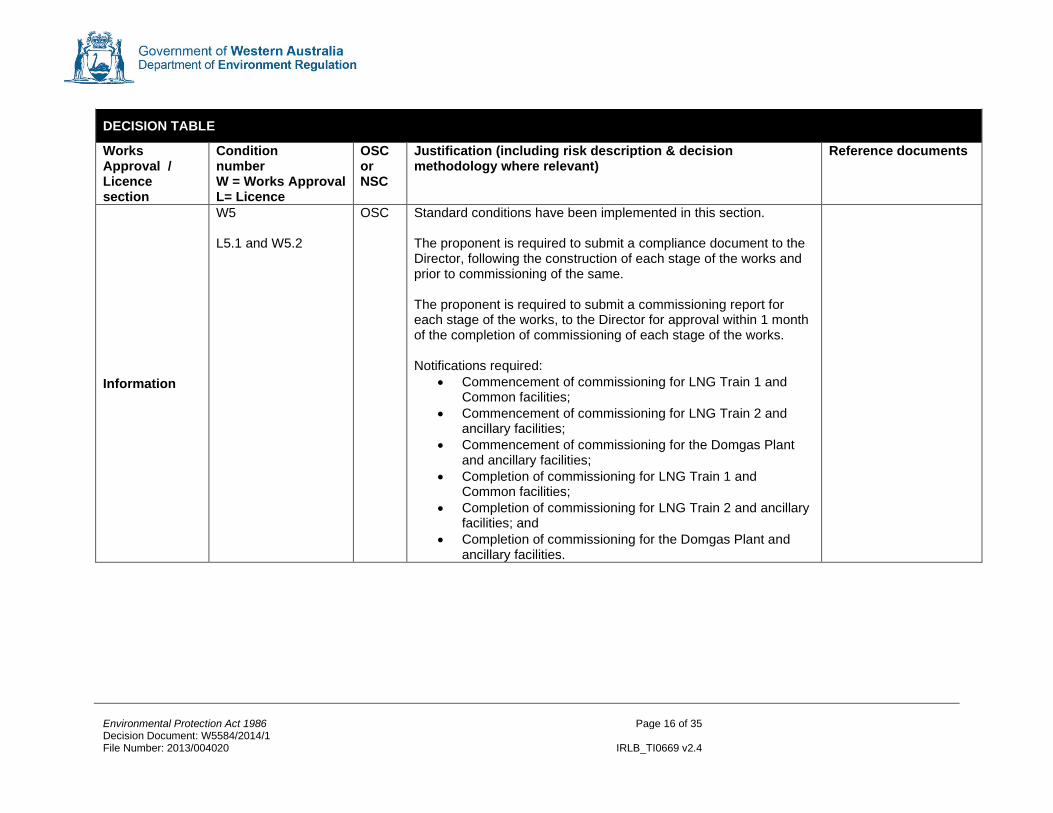
OSC Standard conditions have been implemented in this section. The proponent is required to submit a compliance document to the Director, following the construction of each stage of the works and prior to commissioning of the same. The proponent is required to submit a commissioning report for each stage of the works, to the Director for approval within 1 month of the completion of commissioning of each stage of the works. Notifications required:
• Commencement of commissioning for LNG Train 1 and Common facilities;
• Commencement of commissioning for LNG Train 2 and ancillary facilities;
• Commencement of commissioning for the Domgas Plant and ancillary facilities;
• Completion of commissioning for LNG Train 1 and Common facilities;
• Completion of commissioning for LNG Train 2 and ancillary facilities; and
• Completion of commissioning for the Domgas Plant and ancillary facilities.

Environmental Protection Act 1986 Page 17 of 35 Decision Document: W5584/2014/1 File Number: 2013/004020 IRLB_TI0669 v2.4
5 Advertisement and consultation table
Date Event Comments received/Notes How comments were taken into consideration
27/01/2014 Application advertised in West Australian (or other relevant newspaper)
No comments received N/A
25/3/2014 Proponent sent a copy of draft instrument
Comments were provided on 9 April 2014. Comments were considered and incorporated. To allow flexibility with commissioning, stages of commissioning have been allowed to be specified in the commissioning plan, which is to be approved by the Director of DER.

Environmental Protection Act 1986 Page 18 of 35 Decision Document: W5584/2014/1 File Number: 2013/004020 IRLB_TI0669 v2.4
6 Emissions and discharges risk assessment framework Note: These matrix are taken from the DER Officer’s Guide to Emissions and Discharges Risk Assessment (2006).
Table 2: Measures of Significance of Emissions
Emissions as a percentage of the relevant emission or
ambient standard
Worst Case Operating Conditions (95th Percentile)
>100% 50 – 100% 20 – 50% <20%*
No
rmal
Op
era
tin
g
Co
nd
itio
ns
(50
th
Perc
en
tile
) >100% 5 N/A N/A N/A
50 – 100% 4 3 N/A N/A
20 – 50% 4 3 2 N/A
<20%* 3 3 2 1
*For reliable technology, this figure could increase to 30%
Table 3: Socio-Political Context of Each Regulated Emission
Relative proximity of the interested party with regards to the emission
Immediately Adjacent
Adjacent Nearby Distant Isolated
Level o
f
Co
mm
un
ity
Inte
rest
or
Co
ncern
*
5 High High Medium High Medium Low
4 High High Medium High Medium Low
3 Medium High Medium High Medium Low No
2 Low Low Low Low No
1 No No No No No
Note: These examples are not exclusive and professional judgement is needed to evaluate each specific case *This is determined by DER using the Officer’s Guide to Emissions and Discharges Risk Assessment (2006).
Table 4: Emissions Risk Reduction Matrix
Significance of Emissions
5 4 3 2 1
So
cio
-Po
liti
cal
Co
nte
xt
High A A B C D
Medium High A A B C D
Medium A B B D E
Low A B C D E
No B C D E E
PRIORITY MATRIX ACTION DESCRIPTORS A = Do not allow (fix) B = licence condition (setting limits + EMPs - short timeframes)(setting targets optional) C = licence condition (setting targets + EMPs - longer timeframes) D= EIPs, other management mechanisms/licence conditions (monitoring/reporting)/other regulatory tools E = No regulation, other management mechanisms
Environmental Protection Act 1986 Page 19 of 35 Decision Document: W5584/2014/1 File Number: 2013/004020 IRLB_TI0669 v2.4
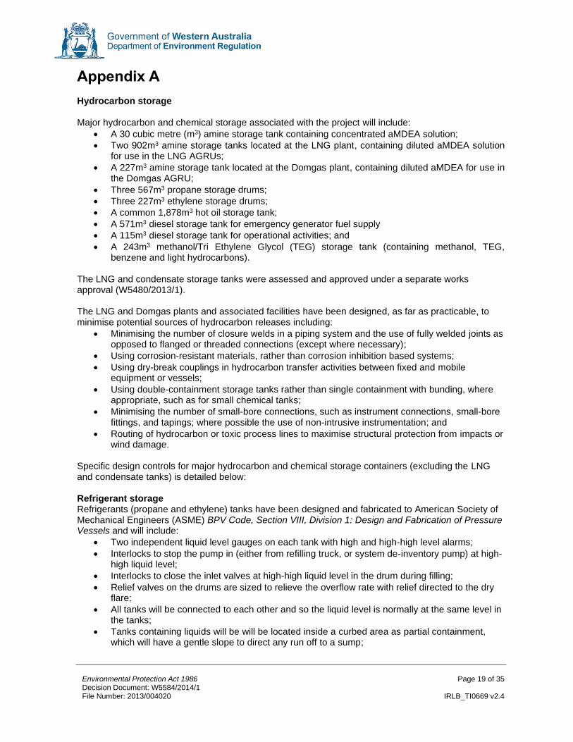
Appendix A Hydrocarbon storage Major hydrocarbon and chemical storage associated with the project will include:
• A 30 cubic metre (m3) amine storage tank containing concentrated aMDEA solution;
• Two 902m3 amine storage tanks located at the LNG plant, containing diluted aMDEA solution for use in the LNG AGRUs;
• A 227m3 amine storage tank located at the Domgas plant, containing diluted aMDEA for use in the Domgas AGRU;
• Three 567m3 propane storage drums;
• Three 227m3 ethylene storage drums;
• A common 1,878m3 hot oil storage tank;
• A 571m3 diesel storage tank for emergency generator fuel supply
• A 115m3 diesel storage tank for operational activities; and
• A 243m3 methanol/Tri Ethylene Glycol (TEG) storage tank (containing methanol, TEG, benzene and light hydrocarbons).
The LNG and condensate storage tanks were assessed and approved under a separate works approval (W5480/2013/1). The LNG and Domgas plants and associated facilities have been designed, as far as practicable, to minimise potential sources of hydrocarbon releases including:
• Minimising the number of closure welds in a piping system and the use of fully welded joints as opposed to flanged or threaded connections (except where necessary);
• Using corrosion-resistant materials, rather than corrosion inhibition based systems;
• Using dry-break couplings in hydrocarbon transfer activities between fixed and mobile equipment or vessels;
• Using double-containment storage tanks rather than single containment with bunding, where appropriate, such as for small chemical tanks;
• Minimising the number of small-bore connections, such as instrument connections, small-bore fittings, and tapings; where possible the use of non-intrusive instrumentation; and
• Routing of hydrocarbon or toxic process lines to maximise structural protection from impacts or wind damage.
Specific design controls for major hydrocarbon and chemical storage containers (excluding the LNG and condensate tanks) is detailed below: Refrigerant storage Refrigerants (propane and ethylene) tanks have been designed and fabricated to American Society of Mechanical Engineers (ASME) BPV Code, Section VIII, Division 1: Design and Fabrication of Pressure Vessels and will include:
• Two independent liquid level gauges on each tank with high and high-high level alarms;
• Interlocks to stop the pump in (either from refilling truck, or system de-inventory pump) at high-high liquid level;
• Interlocks to close the inlet valves at high-high liquid level in the drum during filling;
• Relief valves on the drums are sized to relieve the overflow rate with relief directed to the dry flare;
• All tanks will be connected to each other and so the liquid level is normally at the same level in the tanks;
• Tanks containing liquids will be will be located inside a curbed area as partial containment, which will have a gentle slope to direct any run off to a sump;

Environmental Protection Act 1986 Page 20 of 35 Decision Document: W5584/2014/1 File Number: 2013/004020 IRLB_TI0669 v2.4
• Tanks are fitted with Fire and Gas Detection Systems (FGS) which include flame, point gas, and open path detectors, that will assist in detecting potential leakage; and
• Ethylene tanks include a 9% nickel steel inner vessel and are vacuum jacketed with pearlite insulation.
Amine (aMDEA) and heating oil Amine and heating oil tanks have been designed in accordance with American Petroleum Institute (API) Welded Steel Tanks for Oil Storage and will include:
• Cone/dome roof with nitrogen blanket;
• Vacuum relief and emergency vent; and
• Separate concrete bunds and sumps allowing any overflow or spills to be captured for further processing by the wastewater handling facility.
Waste oil and Methanol/(TEG) The waste oil and Methanol/TEG tanks have been designed in accordance with American Petroleum Institute (API) Welded Steel Tanks for Oil Storage and will include:
• Self-supported roof with nitrogen blanket;
• Separate concrete bunded areas to capture leaks or overflows for removal by vacuum trucks; and
• The concrete bunded areas will be coated with fibre reinforced epoxy, and the Methanol/TEG storage tank epoxy lined internally to prevent corrosion.
Measures to be implemented to manage hydrocarbon and chemical storage will include:
• Handling of fuel and operating facilities in accordance with the Department of Mines and Petroleum Storage and handling of dangerous goods: Code of Practice;
• Procedures in place for operators to ensure safe transfer at unloading or extraction/unloading points;
• Regular facility/equipment inspections, monitoring and maintenance in accordance with operating procedures and safety management system under the plant Major Hazard Facility licence;
• Where the facility exists (i.e. diesel and amine storage), spilt chemicals/hydrocarbons removed through sump vacuum truck extraction points to prevent further impact to the environment and reduce unnecessary loading on the stormwater drainage, sewerage and effluent treatment systems. The cause of spills will be investigated and reported per site operational procedures;
• Groundwater monitoring will be implemented as a means of detecting spills and or leaks; and
• A LDAR program will be developed prior to commissioning to detect leaks. Apart from Works Approval SC 1.2.2 relating to the storage of environmentally hazardous material in accordance with the Department of Mines and Petroleum Code of Practice, no specified conditions relating to the storage of hydrocarbons or chemicals are required on the works approval or licence. OSC 3.8.1 will be included on the licence relating to groundwater monitoring, and any spills will need to be reported in accordance with standard reporting conditions (conditions 5.1 and 5.2).

Environmental Protection Act 1986 Page 21 of 35 Decision Document: W5584/2014/1 File Number: 2013/004020 IRLB_TI0669 v2.4
Appendix B Point source emissions to air including monitoring A requirement of MS873 was the development of an Air Emissions Design Report demonstrating technologies to be employed to ensure the project aligns with best practice standards. The major sources of atmospheric emissions during commissioning and operation of the LNG and Domgas plants are detailed below along with proposed emission controls. When determining emission controls, primary control measures are preferred over secondary abatement. Power Gas Turbine Generators (GTG) Four General Electric (GE) LM6000PF turbines will be installed to power the project, each with capacity to generate 43MW of power (172MW in total). Although three GTGs running at full load will provide sufficient capacity to meet power demands, all four GTGs will be operated at partial load in an N+1 configuration to provide electrical power redundancy and stability, ensuring that sufficient power will be available if one GTG is offline. Stability of the GTGs is essential in maintaining steady state operations of the LNG and Domgas facilities. Under normal conditions, it is expected that the GTGs will operate between 50% and 75% load. Expected emissions from the GTGs are shown in Table 5. Table 5: Power GTG emissions during normal operations.1
Pollutant Design emission rate (g/s)
Design emission concentration
(mg/Nm3)
Emission criteria (mg/Nm3)2
NOx 14.3 49 70
PM10 0.7 2.5 50
SO2 0.02 0.08 -
VOC 0.25 0.9 40
CO 24.3 83 125 Note 1. Reference conditions are dry, 273 degree Kelvin (K), 101.3kPa at 15% O2.
Note 2. New South Wales Protection of the Environment (Clean Air) Regulation 2010.
Controls Design emission rates are based on the implementation of the following emission control measures.
• GE LM6000PF turbines have been selected due to having one of the higher thermal efficiencies compared to other drivers typically used;
• Each GTG will be fitted with Dry Low Emissions (DLE) combustor systems. A key reason for selecting DLE was their ability to control NOx emissions over the entire operating range (50 - 100%);
• Gas turbines will be equipped with inlet air humidification (IAH), which use cooling to improve the overall thermal efficiency and power output during high ambient temperature conditions; and
• Fuel gas will contain low concentrations of H2S due to treatment in the AGRUs resulting in negligible SOx emissions.
Compressor Gas Turbines GE LM6000PF turbines were also selected for refrigerant compressors. Two 50% gas turbines will drive independent propane, ethylene and methane refrigerant loops in parallel per train (6 turbines per train). All of the turbines will operate normally at full capacity and will be controlled simultaneously by a load balancing control program which allows gas turbines to be started, shut down, or placed on recycle without significant upset to the system by adjusting LNG production throughput. Expected emissions from the refrigerant compressor drivers are shown in Table 6.

Environmental Protection Act 1986 Page 22 of 35 Decision Document: W5584/2014/1 File Number: 2013/004020 IRLB_TI0669 v2.4
Table 6: Gas turbine drivers for refrigerant compressors emissions during normal operations.1
Pollutant Design emission rate (g/s)
Design emission concentration
(mg/Nm3)
Emission criteria (mg/Nm3)2
NOx 38 49 70
PM10 3.2 3 50
SO2 0.1 0.1 -
VOC 1 1.0 40
CO 65 83 125 Note 1. Reference conditions are dry, 273 degree Kelvin (K), 101.3kPa at 15% O2.
Note 2. New South Wales Protection of the Environment (Clean Air) Regulation 2010.
Controls Similar to the GTGs, the compressor turbines will be fitted with DLE combustors and IAH. To improve the overall energy efficiency of the LNG trains, WHRUs are proposed to recover waste heat from the compressor gas turbine exhaust stacks for use as process heat within the LNG trains. Other energy optimisation techniques to be employed will include:
• Optimised approach to temperature on the propane refrigerant condensers to reduce compressor power requirements; and
• Incorporated expander-generator in the LNG process train configuration to cool the gas by extracting energy to generate electricity, thus improving the thermal efficiency of the LNG production process and reducing the load on the GTGs.
Process Heaters Gas fired process heaters will be used in two processes:
1. Domgas plant regeneration gas heating for regenerating the molecular sieve dehydration units. This will run continuously only during the heating phase of the regeneration cycle.
2. Hot oil system start –up heater used only during initial start-up, or other periods when neither LNG trains is operation.
Expected emissions from the Domgas regeneration heater and hot oil start-up heater are shown in Table 7. Table 7: Domgas regeneration heater and hot oil start-up heater emissions during normal operations. 1
Pollutant Design emission rate (g/s)
Design emission concentration
(mg/Nm3)
Emission criteria (mg/Nm3)2
Domgas regeneration heater
Hot oil start-up heater
NOx 0.2 .9 102 350
PM10 0.1 0.4 50 50
SO2 0.0005 0.002 0.2 -
VOC 0.02 0.06 7 40
CO 0.1 0.4 52 125 Note 1. Reference conditions are dry, 273 degree Kelvin (K), 101.3kPa at 3% O2.
Note 2. New South Wales Protection of the Environment (Clean Air) Regulation 2010.
Controls The process heaters will only be used on an intermittent basis because the WHRU are capable of capturing sufficient waste heat from the compressor gas turbines to meet most of the heat requirements. The use of WHRUs will preclude the need for the routine use of fired heaters or boilers to provide process heat within the facility reducing combustion emissions.

Environmental Protection Act 1986 Page 23 of 35 Decision Document: W5584/2014/1 File Number: 2013/004020 IRLB_TI0669 v2.4
AGTO The AGTOs will be operated at a firing temperature >760°C and more than one second residence time to achieve a destruction efficiency of greater than 99% for BTEX and H2S. VOCs and H2S is oxidised in the AGTO to CO2 and SO2 respectively. In the event of a failure of the AGTOs for shutdown for maintenance, the acid gas is automatically diverted to the LP stack of the wet flare system. Expected emissions from the AGTOs are shown in Error! Reference source not found.. Table 8: AGTO emissions during normal operations. 1
Pollutant Design emission rate (g/s)
Design emission concentration
(mg/Nm3)
Emission criteria
(mg/Nm3)2
LNG Trains Domgas LNG Trains Domgas
NOx 2.8 0.5 113 110 350
PM10 0.06 0.005 2.2 1.0 50
SO2 1.5 0.1 61 24.2 -
VOC 2.5 0.4 20 20 20
CO 4.3 0.8 1713 1683 125
BTEX4 2.3 0.32 - - -
H2S4 0.008 0.0006 - - - Note 1. Reference conditions are dry, 273 degree Kelvin (K), 101.3kPa at 3% O2.
Note 2. New South Wales Protection of the Environment (Clean Air) Regulation 2010. Note 3: CO emissions concentration is based on vendor guaranteed concentration (150ppmv) and exhaust gas flow. The expected concentration as stated in the vendor proposal is 100 ppmv (<125mg/m3). Note that the feed gas to AGTO is 99% CO2 dry (dry basis), which limits the conversion of VOCs to CO2. Note 4: BTEX and H2S emissions use a vendor guaranteed destruction efficiency of 99%.
Controls Design emission rates are based on the implementation of the following emission control measures:
• The use of aMDEA as the solvent in the AGRU. aMDEA has one of the lowest affinities for hydrocarbons, reducing the amount of dissolved or entrained hydrocarbons within the circulating solvent requiring disposal;
• LP flashing removes most of the entrained hydrocarbons prior to solvent regeneration and is recovered for use as a fuel gas, thus the volume of entrained hydrocarbons in the acid gas stream requiring disposal via the AGTO is reduced;
• The stack height of the AGTO will be specified to 35 m to assists with the dispersion of formed SO2 and any remaining VOCs/H2S; and
• The destruction efficiency will be maintained by continuous monitoring of the combustion chamber temperature, oxygen in the flue gas and by maintaining the design residence times.
Flaring There are three flare derricks to support the Wheatstone LNG Project:
• LP with three flare risers (Wet, dry and spare);
• HP with three flare risers (wet, dry and spare); and
• Marine flare. Flares will be elevated (95 m, 45 m and 45 m for the HP, LP and Marine flares respectively) to aid in dispersion of emissions and also reduce the possibility of thermal radiation exposure to the workforce and facilities. Each of the wet and dry gas flare systems will consist of a large collection header with a series of laterals into each plant area; a liquid knockout and pumps, a demountable flare stacks with specially designed burner tips; the LP flare is air assisted with variable-speed controlled air blowers and the HP flare uses a sonic multi-jet tip for increased mixing. A spare flare knockout drum and flare stacks are provided to serve as a common back up system to both the wet and dry flare system, allowing either system to be taken out of service for inspection or maintenance.

Environmental Protection Act 1986 Page 24 of 35 Decision Document: W5584/2014/1 File Number: 2013/004020 IRLB_TI0669 v2.4
Flaring will be minimised during routine operations by the following measures:
• No routine flaring; flaring should only occur during unusual situations such as emergencies, process upsets, plant start-up and shutdowns;
• Where possible, all routine sources of hydrocarbon emissions will be recycled back into the process or recovered for use as fuel or product;
• Hydrocarbons separated in the AGRU Rich Amine Flash Drums will be recovered and used as LP fuel gas;
• Hydrocarbon vapour generated in the LNG storage and loading system will be recompressed by BOG compressors to the methane refrigerant loop;
• BOG compression capacity will be sufficient to avoid any BOG to the marine flare (except during de-inerting of LNG carries);
• Suitably sized knockout drums in the flare systems remove liquids from gas to be flared;
• The plant process and equipment has been designed to operate for four years between major maintenance shutdowns to minimise start-up and shutdown periods;
• The LNG train configuration and compressor design will allow the process refrigerants to remain contained within the refrigerant system during shutdown and restart. In instances where depressurisation must occur, propane and ethylene storage drums will be provided, with sufficient capacity to store the entire refrigerant inventory for one LNG train plus additional capacity for refrigerant makeup.
Estimated emissions from the flares are shown in Table 9. Table 9: Estimated emission from flares.
Pollutant Design emission rate - Routine (g/s)1
Design emission rate - Upset (g/s) 2
Dry flare Wet flare Marine flare
Dry flare2 Wet flare3 Marine flare4
NOx 0.43 0.44 0.03 9.1 4.7 32.4
PM10 0.09 0.09 0.01 1.8 1 6.6
SO2 0.001 0.001 0.0001 0.08 1.4 0.0003
VOC 0.02 0.02 0.002 1.14 0.25 0.4
CO 3.7 3.8 0.3 78.1 40.5 278 Note 1. Estimated from flares during routine operations (pilot and purge). Note 2. Upset scenario based on a blocked NRU vent outlet. Note 3. Upset scenario based on a thermal oxidiser trip. Note 4. Upset scenario based on a loss of a BOG compressor.
The flares are designed to operate smokeless during most flaring operations with visible emissions of Ringelman 1 or lower (i.e. 20% opacity or lower). Flares are not designed for smokeless operation during infrequent, unusual emergency relief scenarios such as failure of the main refrigerant compression shutdown during a plant power failure. Measures to minimise dark smoke emissions from flaring include:
• Air assists flares in the first stage of LP wet and dry flares, and marine flare;
• HP flare tips generate sufficient turbulence at the flare tips to ensure good mixing of air and hydrocarbons and therefore do not require air assist to aid combustion;
• Staging of flares to handle the large range of relief flow rates from the LNG trains and Domgas units. Staging maintains sufficient back pressure to provide sufficient driving force for mixing at the flare tips; and
• Flares have been designed with velocity seals to help reduce the purge gas volume required to protect the stack against air infiltration.
Modelling Air quality modelling was conducted and reviewed by DER’s Air Quality Management Branch (AQMB). The model approach was determined to be satisfactory with correct inputs and the model used, and that the proposal will only have minor impacts on regional air quality.

Environmental Protection Act 1986 Page 25 of 35 Decision Document: W5584/2014/1 File Number: 2013/004020 IRLB_TI0669 v2.4
The modelling assessment utilised two models; AERMOD for predicting local impacts (out to 13km from the Wheatstone Project), and TAPM-CTM for predicting regional scale ozone and NO2 impacts. Modelling assessed air emissions from the following sources:
• 12 compressor gas turbines;
• Four power generation gas turbines;
• Three recuperative thermal oxidisers (RTO) (one for each LNG train, and one for the Domgas plant);
• The regeneration gas process heater and hot oil start up process heater;
• Flare system;
• VOC emissions from condensate shiploading; and
• Ship combustion sources from the LNG and condensate carriers and tugs. Six operational scenarios were modelled:
1. Normal operations; 2. RTO trip for one of the LNG trains where the AGRU vent gas is directed to the low pressure
flare; 3. Blacked NRU outlet vent resulting in gas vented directly to atmosphere consisting of
concentrated N2, with trace amounts of methane; 4. Loss of BOG compressors where the BOG from the LNG tankers is routed to the marine flare; 5. Loading a condensate ship, where VOC rich vapours are displaced from the shops hold; and 6. Start-up of an LNG train with the use of a start-up oil heater and non-routine flaring to the LP
flare. Modelling assessed predicted ambient air concentrations against the National Environment Protection Measures (NEPM) for ambient air quality and air toxics. Results of the modelling using AERMOD to assess local impacts are shown in Table 10. Table 10: Predicted maximum concentration (as a per cent of the NEPM criteria) from the Wheatstone Project (8.9mtpa) outside the lease boundary (background levels included).
Pollutant Ave.
Period Conc.
Statistic Criteria Back-
ground
Routine Non Routine
Case 1 Case
2 Case
3 Case
4 Case
5 Case
6
CO 8-hour Max 9,000 ppb 1.1 1.6 1.6 1.6 1.6 1.6 1.5
NO2 1-hour Max 120 ppb 1.7 23.2 23.2 23.2 23.2 23.2 15.9
Annual Ave 30 ppb 3.3 8.0 8.0 8.0 8.0 8.0 8.2
SO2
1-hour Max 200 ppb 0 0.5 0.3 0.5 0.5 0.5 0.3
24-hr Max 80 ppb 0 0.4 0.2 0.4 0.4 0.4 0.2
Annual Ave 20 ppb 0 0.2 0.2 0.2 0.2 0.2 0.1
PM10 24-hr Max 50 µg/m3 54 56 56 56 57 56 56
PM2.5 24-hr Max 25 µg/m3 24 29 29 29 29 29 27
Annual Ave 8 µg/m3 62.5 66 66 66 66 66 65
Benzene Annual Ave 5 µg/m3 0.6 2.1 1.9 2.0 2.1 4.9 1.8
Toluene 24-hr Max 1,000 ppb 0.05 0.03 0.02 0.03 0.03 0.40 0.02
Annual Ave 100 ppb 0.05 0.08 0.08 0.08 0.08 0.21 0.07
Xylenes 24-hr Max 250 ppb 0.05 0.06 0.06 0.06 0.06 0.67 0.05
Annual Ave 200 ppb 0.015 0.02 0.02 0.02 0.02 0.05 0.01
Formaldehyde 24-hr Max 40 ppb 0.55 1.6 1.6 1.6 1.6 1.6 1.5
H2S 1-hour 99.9th 1.11 µg/m3 0 1.0 0.6 1.0 1.0 1.0 0.7

Environmental Protection Act 1986 Page 26 of 35 Decision Document: W5584/2014/1 File Number: 2013/004020 IRLB_TI0669 v2.4
Results show that, with the exception of PM10 and PM2.5, ambient air quality criteria will be met. Exceedances of PM10 and PM2.5 are attributed to already high background concentrations, and not a result of the Wheatstone Project. The Wheatstone Project will contribute to increases of NOx in the ambient airshed, however, NOx concentrations are predicted to remain well below the NEPM during normal and upset conditions (only 23.2% of the 1-hour criteria). All other criteria, apart from PM10 and PM2.5, are predicted to be below 5% of the NEPM criteria. Results of modelling using TAPM-CTM to assess impacts to regional air quality are shown in Table 11. Table 11: Predicted maximum concentration of Ozone and NO2 anywhere on the model grid as a percentage of the criteria.
Pollutant Ave.
Period Conc.
Statistic Criteria
Back-ground (2009)
Routine Non Routine
Case 1 Case
2 Case
3 Case
4 Case
5 Case
6
NO2
1-hour Max 120 ppb 63 63 63 63 63 63 63
1-hour 2nd 120 ppb 38 38 38 38 38 38 38
Annual Ave 30 ppb 31 31 31 31 31 31 31
Ozone
1-hour Max 100 ppb 87 86 86 86 86 86 86
1-hour 2nd 100 ppb 74 67 67 67 67 68 67
4-hour Max 80 ppb 95 94 94 94 94 94 94
4-hour 2nd 80 ppb 86 79 79 79 79 80 79
Monitoring Monitoring will include monitoring of emissions concentrations and monitoring of major point sources for important parameters to ensure proper functioning of equipment. Details of the proposed point source emissions testing program is provide in Table 12. Full details of the monitoring program will be provided to DER as details are determined closer to commissioning. Table 12: Proposed point source air emissions monitoring.
Emission Point Source
Parameter Method Frequency
Power GTG and compressor gas turbines
Fuel gas consumption Fuel gas flow meter Continuous
Fuel gas composition Online composition analyser
Continuous
Flow rate and concentration of specified atmospheric pollutants (NOx, CO and VOC) in the exhaust stream
Stack testing using approved testing methods
Quarterly
AGTO Gas flow rates to AGTO Online metering and totalising
Continuous
Flow rate and concentration of specified atmospheric pollutants (CO and VOC) in the exhaust stream
Calibrated portable analyser
Quarterly
Acid gas composition Stack testing Annually
Combustion chamber temperature
Online monitoring Continuous
Oxygen monitoring in flue gas
Online monitoring Continuous
Process Heaters Flow rate and concentration of specified atmospheric
Stack testing using approved testing methods
Annually for the first three years

Environmental Protection Act 1986 Page 27 of 35 Decision Document: W5584/2014/1 File Number: 2013/004020 IRLB_TI0669 v2.4
pollutants (NOx, CO and VOC) in the exhaust stream
Fuel gas consumption Fuel gas flow meter Continuous
Oxygen monitoring in flue gas
Online monitoring Continuous
Flares Composition of major stream venting to the flare header
Manual sampling Annually
Gas flow rates to flare headers. Pilot gas and purge gas flow rates are also measured.
Online metering and totalising
Continuous
Dark smoke emissions Operators monitor Closed Circuit Television (CCTV) camera system for dark smoke. If smoke is detected opacity of smoke will be
determined to confirm compliance with emission limits.
Fugitive emissions
VOC emissions Remote imaging, handheld infrared camera
Quarterly to annually
depending on source and
frequency of leaks
Fuel gas Composition at the main High Pressure (for turbines) and Low Pressure (flares, heaters, etc.) fuel gas headers
Online monitoring Continuous
A LDAR program will be developed for the plant, consisting of periodic monitoring to detect leaking components, followed by repair of the components and retesting to ensure that the leak has been corrected. Potential leak sources will be monitoring on a frequency ranging from quarterly to annually using remote imaging technology. The LDAR program will be finalised prior to commissioning and will consider applicable specifications contained in the USEPA Method 21 Determination of Volatile Organic Compound Leaks, including a Flame Ionization Detector or Photo Ionization Detector as recommended by the EPA in Report 1404. During initial construction and all major turnarounds, a Flange Management System (FMS) will also be implemented to track the status and condition of all flanges, prevent leaks and assure the long term integrity of the flanges. Ambient air quality monitoring The current baseline air quality monitoring program will be expanded to include the existing and proposed monitoring stations shown in Figure 3. The location of monitoring sites was selected based on:
• the location of sensitive receptors;
• potential areas of relatively higher air pollutant concentrations as identified by the air modelling studies; and
• AS 3580.1.1 Methods for the Sampling and Analysis of Ambient Air – Part 1.1: Guide to Siting Air Monitoring Equipment.
A summary of the monitoring program is provided in Table 13. Inclusion of mercury in the ambient monitoring program is a precautionary measure as concentrations of mercury in the raw feed gas are unknown. The program may be revised depending on results of emissions testing.

Environmental Protection Act 1986 Page 28 of 35 Decision Document: W5584/2014/1 File Number: 2013/004020 IRLB_TI0669 v2.4
Table 13: Proposed ambient air quality monitoring program.
Project phase Monitoring stations
Pollutants to be monitored
Monitoring equipment Frequency
Commissioning Existing stations
NOx, SOx, VOC Particulate Matter,
Passive Diffuse Samplers One week per month
Dust Deposition OSIRIS Particle Counters 10-minute averages
Proposed stations
VOC Passive Diffuse Samplers One week per month
Dust Deposition OSIRIS Particle Counters 10-minute averages
Particulate Matter TEOMs Continuous
SOx UV Absorption Continuous
NOx Chemiluminescence Continuous
Operations Existing and proposed
VOC Passive Diffuse Samplers One week per month
Dust Deposition OSIRIS Particle Counters 10-minute averages
Particulate Matter TEOMs Continuous
SOx UV Absorption Continuous
NOx Chemiluminescence Continuous
Mercury Differential optical absorption spectroscopy (DOAS)
Continuous
In addition to the monitors shown in Figure 3, there are two monitors, currently operated by Bechtel, at the Ashburton North Village that monitor the airshed at the Village and determine impacts from local sources such as the Construction Village Power Station. The monitors will continue to be operated under the control of Bechtel during the operation of the Ashburton North Village. Limits/Targets DER has determined that the overall impact of air emissions is low. DER has reviewed the proposed operational controls outlined in the Air Emissions Design Report – Foundation Project (2013) (required by M873) and is confident that the project will be implemented in line with best practice standards. The EPA, in report 1404, recommended:
• Targets for BTEX and mercury based on model assumptions;
• Targets for flares: o Volume per year or volume per tonne of LNG produced each year; and o Number of hours of black smoke per year.
To ensure that equipment will meet design specifications, OSC setting limits and targets will be included on the licence. This will include emission targets/limits on point sources listed including the GTG, compressor drivers, AGTO, etc.as well as limits/targets for ambient air quality. Targets and limits for dark smoke emissions will also be included on the licence, specifying reporting requirements based on the duration of dark smoke emissions of particular opacity. Emissions Monitoring Conditions will be implemented on the works approval requiring pre-commissioning and commissioning plans to be submitted outlining how air emissions will be managed during the individual commissioning phases. The licence will set conditions relating to point source (OSC 3.2) and ambient air quality monitoring (OSC 3.8). Conditions relating to the monitoring of dark smoke emissions will also be included. Full details of the operational monitoring program will need to be provided with the licence application. To ensure that stack sampling ports are maintained in accordance with the relevant Australian Standard, OSC 3.2.2 will be included on the licence.
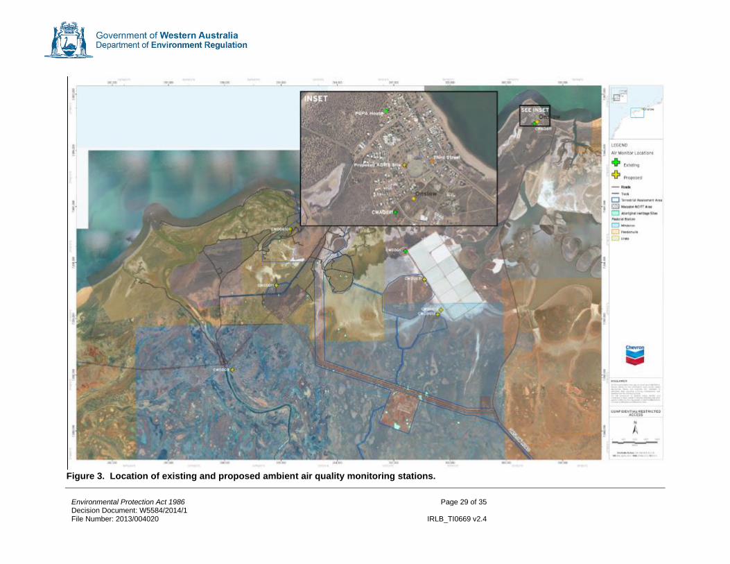
Environmental Protection Act 1986 Page 29 of 35 Decision Document: W5584/2014/1 File Number: 2013/004020 IRLB_TI0669 v2.4
Figure 3. Location of existing and proposed ambient air quality monitoring stations.

Environmental Protection Act 1986 Page 30 of 35 Decision Document: W5584/2014/1 File Number: 2013/004020 IRLB_TI0669 v2.4
Appendix C Emissions to land and surface water including monitoring Water streams from the premises consists of two main steams; wastewater and stormwater. Wastewater Wastewater consists of process wastewater and sanitary wastewater. Process wastewater are water streams which are contaminated or have the potential for contamination with oil or hydrocarbons. Sources of process wastewater include:
• Drains from machinery base plates;
• Water drawoffs and blowdowns for vessels containing hydrocarbons;
• Maintenance drains
• Effluent from Wet Gas knockout drums;
• Combustion turbine detergent washings and drains from the compressor area collection tanks;
• Combustion turbine detergent washings and drains from the power generation area;
• Wastewater from the AGTO knockout drum;
• Washdown from the GTG area;
• Discharges from the stabiliser system;
• Discharges from the dehydration unit and AGRU systems; and
• Blowdown of wastewater contaminated with soluble amine from the AGRU. Process flow rates and concentration of contaminants are variable. The streams will be collected in oily wastewater lift stations and sent to the primary treatment units, which include corrugated plate interceptors (CPI) and dissolved air flotation. Discharge from the primary treatment units will be combined with sanitary wastes and makeup water treatment waste streams, and discharged to an outfall. This will be assessed under a separate works approval. Sanitary wastes include sewage inflows, which will be directed to the Primary Sanitary Treatment Plant and will be the subject of a separate works approval. A summary of wastewater streams, including expected volumes and pollutants, is provided in Table 14. Table 14: Expected volume and contaminants associated with wastewater discharge streams.
No. Water Streams Volume (m3/day)
Expected Contaminants
1 Makeup Water Treatment Waste Streams (1&2)
6367.2 Total dissolved solids (TDS) and total suspended solids (TSS)
2 Treated Effluent from Village Sanitary Wastewater Treatment System (1)
196.8 Biochemical oxygen demand (BOD), TSS, Total Nitrogen and Total Phosphorus
3 Sanitary Wastewater from LNG Plant Area (Site) (1)
28.8 BOD, TSS, Total Nitrogen and Total Phosphorus
4 Filtered Biologically-Treated Wastewater from Activity Sludge trains A/B Site sanitary Wastewater Treatment System(1)
28.8 BOD, TSS, Total Nitrogen and Total Phosphorus
5 Combined Effluent Sump To Permitted Permanent Ocean Outfall Discharge Diffuser (1)
6617 TDS, Total Nitrogen and Total Phosphorus
6 Feed to Primary Treatment System 24 Lubricating type oils and TSS
7 Filtered Process Area Wastewater to 24 Lubricating type oils and TSS

Environmental Protection Act 1986 Page 31 of 35 Decision Document: W5584/2014/1 File Number: 2013/004020 IRLB_TI0669 v2.4
Combined Effluent Sump
8 Wastewater from Process Blowdown NA(3) Lubricating type oils and TSS
9 Skimmed Oily First Flush Water NA(4) Lubricating type oils and TSS Note 1: This stream is not in the scope of the current works approval. Note 2: The “Makeup Water Treatment Waste Streams” is a compilation of three streams from Reverse Osmosis Reject, Area Sumps and Blowdown drains from different turbine inlet air humidifiers. Note 3: Normally no flow. Note 4: Normally no flow. After a stormwater event stormwater collected in each first flush sump is sampled and if sampling indicates contamination the water is pumped to treatment.
Stormwater The stormwater system is designed to segregate stormwater runoffs of different risks of contamination. This includes four categories:
• Contaminated runoffs - runoff occurring in areas that have a high risk of contamination including process areas and other areas involved in handling hydrocarbons;
• Potentially contaminated runoffs – runoffs from areas with a moderate or low risk of contamination such as the storage tank areas and car parks;
• On-site clean (uncontaminated) runoffs – runoffs from low risk areas where contaminants are unlikely such as unpaved areas, roadways and rooftops; and
• Intercepted offsite clean runoffs. Contaminated runoff is treated in a first flush system where the first 25 mm of stormwater runoff from process area is collected in first flush sumps. Runoff in excess of the first 25 mm are considered clean and diverted to an overflow weir to a sedimentation pond. Following a rainfall event water collected in the first flush sumps is sampled to determine if it is contaminated or clean. Water quality meeting set criteria (Table 15) is considered “clean” and is forwarded to the sedimentation ponds. Water not meeting the criteria is forwarded to the Primary Treatment System and ultimately discharged to the outfall. Contaminated runoffs treated in the Primary Treatment System are sampled and monitored via continuous composite sampling. Criteria will be set for discharges to the outfall which will be assessed under a separate works approval. Table 15: Water quality criteria for stormwater discharges.
Parameter Criteria
pH 6 – 8
Turbidity 370 NTU
Total petroleum hydrocarbons 15 mg/L1 Note 1: EPA Report 1404 recommended a total petroleum concentration of 1 mg/L, however, 15 mg/L is consistent with the Department of Water’s Water Quality Protection Note 68 Mechanical equipment washdown (2006).
Stormwater from non-process areas that is not considered contaminated is captured by the stormwater and surface runoff systems and directed to stormwater sedimentation ponds for controlled release to the environment. 10 ponds will be located around the premises to capture stormwater runoff. Water will be tested for the parameters shown in Table 14 to ensure that criteria are being met. Release to the environment will be via percolation (the ponds are not lined), evaporation or controlled discharge via discharge culverts. A diagram showing the wastewater and stormwater streams is provided in Figure 4, detailing the sources, treatment and disposal method.

Environmental Protection Act 1986 Page 32 of 35 Decision Document: W5584/2014/1 File Number: 2013/004020 IRLB_TI0669 v2.4
Figure 4. Process diagram showing water discharges.

Environmental Protection Act 1986 Page 33 of 35 Decision Document: W5584/2014/1 File Number: 2013/004020 IRLB_TI0669 v2.4
Limits/Targets Targets for emissions to land via sedimentation ponds will be set through licence conditions (OSC 2.5) in accordance with Table 14. Wastewater streams discharging to the ocean outfall are not assessed under this works approval and will be assessed under a separate works approval. Should the assessment of the outfall deem that water quality or environmental impact are not satisfactory, further improvements or retrofitting of the waste treatment systems may be required to meet water quality criteria. Emissions Monitoring Conditions relating to monitoring stormwater quality will be imposed through OSC 3.5. An operations stormwater management plan will be developed to support the Licence Application. A stormwater monitoring procedure will be developed to include full details of the stormwater monitoring program. This will be submitted with the licence application.

Environmental Protection Act 1986 Page 34 of 35 Decision Document: W5584/2014/1 File Number: 2013/004020 IRLB_TI0669 v2.4
Appendix D Noise emissions Noise emissions were modelled to predict noise levels associated with the operation of the LNG and Domgas Plants (including emergency flaring) at nearby sensitive receptors. Results of noise modelling are shown in Table 16. Table 16: Predicted noise levels (LA10 dB(A)) during operations
Sensitive receptors
Assigned night-time
levels
Background night-time
(LA90)
Predicted noise at worst wind conditions
Normal operations
Emergency flaring
Onslow 35 34 27 30
4 Mile Creek N/A 36 37 41
5 Mile Pool N/A 25 28 32
Old Onslow Heritage Site
N/A 25 36 41
10 Mile Dam 35 24 24 27
Onslow Salt 65 - 35 41
Modelling was reviewed by DER’s Noise Regulation Branch and it was determined that noise from operation of the LNG and Domgas plants would be able to be managed to comply with the Environmental Protection (Noise) Regulations 1997. It was noted however that the Brolga Camp, an accommodation facility is located adjacent to the Macedon Gas Project 2 km south of the project area, was not included in the noise assessment. The predicted noise levels from the LNG and Domgas plants would exceed the night-time assigned noise levels at this camp (Figure 5 and Figure 6). However, given that the camp will only be used on a temporary basis to support the construction of the Wheatstone Project, the EPA aspirational goal (Draft Guidance No. 8: Guidance for Environmental Noise) of 40 dB(A) (LA10) and 50 db(A) (LAmax) can be applied. DER is satisfied that the aspirational goal can be met at the Brolga Camp.
Figure 5. Predicted noise levels (LA10 dB(A)) at sensitive receptors during normal operations

Environmental Protection Act 1986 Page 35 of 35 Decision Document: W5584/2014/1 File Number: 2013/004020 IRLB_TI0669 v2.4
Figure 6. Predicted noise levels (LA10 dB(A)) at sensitive receptors during emergency flaring Measures in place to minimise noise include:
• Construction activities will be limited to daylight hours unless approved otherwise;
• Vehicle and equipment will be regularly maintained in accordance with manufacturer specifications;
• During construction, low noise equipment will be used where practical;
• Noise complaints will be recorded and investigated; and
• Acoustic enclosure will be provided around rotating and other ‘noisy’ equipment if deemed necessary.
Limits/Targets No limits or targets will be set on the works approval or licence for noise. Emissions Monitoring Noise monitoring outside of the premises boundary is not proposed during construction or commissioning, however, noise monitoring will be conducted regularly within the boundary during commissioning and operations to validate equipment noise levels. OSC 4.1.1 of the works approval requires the submission of a commissioning plan. The commissioning plan will need to detail equipment noise verification monitoring, with results reported to DER to confirm equipment noise levels are in compliance with those were utilised in the model. Results of equipment noise verification will be reviewed by DER’s Noise Regulation Branch to determine if further noise monitoring is required.