December 3-4, 2007Earthquake Readiness Workshop Seismic Design Considerations Mike Sheehan.
33
December 3-4, 2007 Earthquake Readiness Workshop Seismic Design Considerations Mike Sheehan
-
Upload
gerald-thompson -
Category
Documents
-
view
232 -
download
1
Transcript of December 3-4, 2007Earthquake Readiness Workshop Seismic Design Considerations Mike Sheehan.

December 3-4, 2007 Earthquake Readiness Workshop
Seismic Design Considerations
Mike Sheehan

December 3-4, 2007 Earthquake Readiness Workshop
Overview
• Seismic Environment Defined
Forces to be applied to the structures
• Observatory Seismic Design Process
– Buildings, Enclosures and Equipment
– Telescopes and Instruments
Methodology and design criteria
• Special Structural Features
– Seismic Restraints
– Seismic Isolation
• Retrofit

December 3-4, 2007 Earthquake Readiness Workshop
Resources
• Seismic Design Requirements– Uniform Building Code
– International Building Code
– Local codes
– Many others
• Site Specific Seismic Hazard Analysis
** Requirements change over time to reflect new knowledge of the seismic environments in different geographic areas
–Hawaii change from Zone 3 to Zone 4 in the late 90’s
–Seismic retrofit should be a big consideration for all Observatories

December 3-4, 2007 Earthquake Readiness Workshop
Design Methodology Choices
• Static Lateral Force Procedure– Peak base shear force is calculated by manipulation of loads of
information including:• Soil profile type• Seismic source classification• Structural configuration• Proximity to the source• Ground response coefficients• Response spectra• Redundant load path considerations• Seismic dead load• Fundamental period of vibration of the structure
• Dynamic Analysis– Based upon “Appropriate Ground Motion Representation”– Performed using “Accepted Principles of Dynamics”

December 3-4, 2007 Earthquake Readiness Workshop
Static Lateral Force Procedure
Base Shear Force
F1
F2
F3
F4
Base Vertical Force
December 3-4, 2007 Earthquake Readiness Workshop
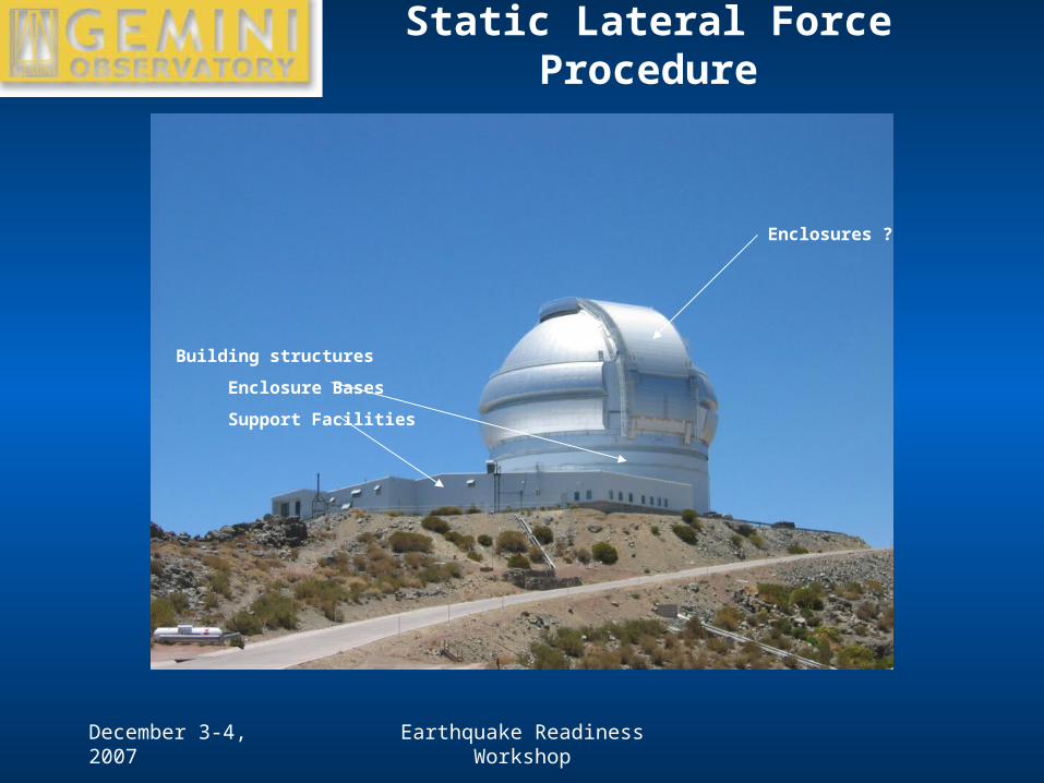
Static Lateral Force Procedure
Building structures
Enclosure Bases
Support Facilities
Enclosures ?

December 3-4, 2007 Earthquake Readiness Workshop
Static Lateral Force Procedure
Equipment Racks
Tanks

December 3-4, 2007 Earthquake Readiness Workshop
Static Lateral Force Procedure
More Tanks

December 3-4, 2007 Earthquake Readiness Workshop
Static Lateral Force Procedure
Piping Systems Computer Racks

December 3-4, 2007 Earthquake Readiness Workshop
Dynamic Analysis
• Analysis– Mathematical model required (finite element model)
– Enough vibration modes to describe total structural response must be included

December 3-4, 2007 Earthquake Readiness Workshop
Site-Specific Seismic Hazard Analysis
At a specific site –
• The Site-Specific SHA results include-– The probability of occurrence of earthquakes near the site with
magnitudes sufficiently high that they may impact the design characteristics of structures at the site.
– Ground accelerations at the site associated with these earthquakes
• Then - with some set criteria –– The SHA defines the design seismic environment in such terms that a
proper structural analysis and design can proceed.• Seismic response spectra
• Representative ground acceleration time histories

December 3-4, 2007 Earthquake Readiness Workshop
Earthquake HistoryFecha Hora Latitud Longitud Ms Prof (km) Mw
Efec. Sec.
21-05-1960 6:02 -37.5 -73.5 7.3 - - -
22-05-1960 6:32 -37.5 -73 7.3 - - -
22-05-1960 15:11 -39.5 -74.5 8.5 - 9.5 TD
19-06-1960 22:01 -38 -73.5 7.3 - - -
01-11-1960 4:45 -38.5 -75.1 7.4 55 - -
13-07-1961 17:19 -41.7 -75.2 7 40 - -
14-02-1962 2:36 -37.8 -72.5 7.3 45 - -
03-08-1962 4:56 -23.3 -68.1 7.1 107 - -
23-02-1965 18:11 -25.67 -70.63 7 36 - -
28-03-1965 12:33 -32.418 -71.1 7.4 68 - -
28-12-1966 4:18 -25.51 -70.74 7.8 23 - -
13-03-1967 12:06 -40.12 -74.68 7.3 33 - -
21-12-1967 22:25 -21.8 -70 7.5 33 - -
17-06-1971 17:00 -25.402 -69.058 7 76 - -
08-07-1971 23:03 -32.511 -71.207 7.5 40 - TM
18-08-1974 6:44 -38.453 -73.431 7.1 36 - -
10-05-1975 10:27 -38.183 -73.232 7.7 6 - -
29-11-1976 21:40 -20.52 -68.919 7.3 82 - -
03-08-1979 14:11 -26.518 -70.664 7 49 - -
16-10-1981 0:25 -33.134 -73.074 7.5 33 - -
04-10-1983 14:52 -26.535 -70.563 7.3 14 - -
03-03-1985 19:46 -33.24 -71.85 7.8 33 8 T
08-04-1985 21:56 -34.131 -71.618 7.5 37 - -
05-03-1987 6:17 -24.388 -70.161 7.3 62 - T
08-08-1987 11:48 -19 -70 7.1 42 - -
30-07-1995 1:11 -23.36 -70.31 7.3 47 8 T
13-06-2005 18:44 -19.895 -69.125 7.8 108 7.8
Define –•Probability of occurrence of significant events
•Recurrence rate of similar events

December 3-4, 2007 Earthquake Readiness Workshop
Project Ground Motion from Source to Site
Ground Motion Attenuation Equations
•Source to site distance
•Source depth
•Geology and site soil conditions
•Other factors

December 3-4, 2007 Earthquake Readiness Workshop
Site-Specific Seismic Hazard Analysis
• Establish your own Design Criteria– Codes requires that you design for the “Survival Event”
• This is typically defined as an event that has a 10% probability of being exceeded in 50 years.
• In this case, structural elements are required to stay intact.
• But – some limited failures are expected.
• Design criteria for this event should be specific
– Damage limited to a level where the Observatory is back in a fully operational state within “X” weeks or months.
– No failures of fragile optics and instruments
– At Gemini, we have designed for an “Operational Event” as well.• This was chosen to be an event that produced seismic loads at a level of 80%
of the Survival Event.
• In this environment, the design criteria was that structural elements remain fully elastic and that the telescope would recover to full operational capacity after full system checks (offline for 1 night)

December 3-4, 2007 Earthquake Readiness Workshop
Site-Specific Seismic Hazard Analysis
Design levels for Peak Ground Acceleration
Survival Event10% Probability
of exceeding in 50 years
Average Return Period = 500 years
PGA = 0.40 g
Operational Event22% Probability
of exceeding in 50 years
Average Return Period = 200 years
PGA = 0.32 g

December 3-4, 2007 Earthquake Readiness Workshop
Site-Specific Seismic Hazard Analysis
Horizontal Ground Motion Response Spectrum
Operational Event

December 3-4, 2007 Earthquake Readiness Workshop
Site-Specific Seismic Hazard Analysis
Horizontal Ground Motion Response Spectrum
Survival Event

December 3-4, 2007 Earthquake Readiness Workshop
Site-Specific Seismic Hazard Analysis
Vertical Ground Motion Response Spectrum
Vertical Ground Motion Response Spectrum
0.01
0.1
1
0.01 0.1 1 10
Period (sec)
Ac
ce
lera
tio
n (
g)
200 yr Event
500 yr Event
•Note that Codes typically scale the vertical response spectrum at 2/3 the horizontal spectrum. Here at 10 hz, the vertical and horizontal spectral values are equal.

December 3-4, 2007 Earthquake Readiness Workshop
Site-Specific Seismic Hazard Analysis
• Generation of Site-Specific ground motion acceleration time history records– Use recorded ground motion records from sensors located near the site.
– Calculate the response spectra based upon the measured data.
– Modify the time data as necessary so that its corresponding response spectra matches that calculated for the site in the SHA
Modified Mauna Loa Weather Observatory Accelerogram from 11/16/83 EarthquakeD&M Data Set COMP2A
-0.4
-0.3
-0.2
-0.1
0
0.1
0.2
0.3
0.4
0 5 10 15 20 25 30 35 40 45
Time (sec)
300o
Co
mp
on
ent
Acc
eler
atio
n (
G)
December 3-4, 2007 Earthquake Readiness Workshop
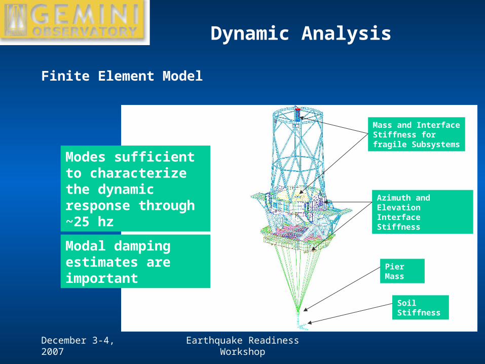
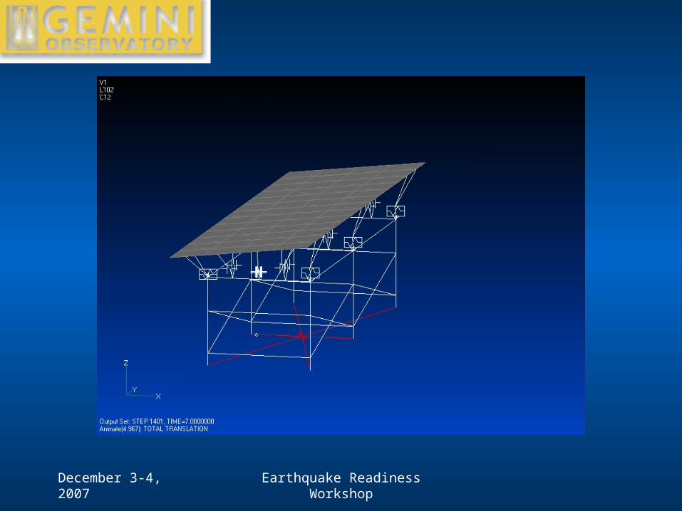
Dynamic Analysis
Finite Element Model
Soil Stiffness
Pier Mass
Azimuth and Elevation Interface Stiffness
Mass and Interface Stiffness for fragile Subsystems
Modes sufficient to characterize the dynamic response through ~25 hz
Modal damping estimates are important

December 3-4, 2007 Earthquake Readiness Workshop
Dynamic Analysis
Modal Analysis
•Mode 1
fn = 2.8 hz
cc = 9.2%
•Mode 8
fn = 6.0 hz
cc = 1.4%
December 3-4, 2007 Earthquake Readiness Workshop
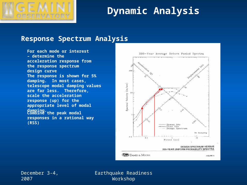
Dynamic Analysis
Response Spectrum Analysis
For each mode or interest – determine the acceleration response from the response spectrum design curve
The response is shown for 5% damping. In most cases, telescope modal damping values are far less. Therefore, scale the acceleration response (up) for the appropriate level of modal damping.
Combine the peak modal responses in a rational way (RSS)

December 3-4, 2007 Earthquake Readiness Workshop
Dynamic Analysis
• Transient Analysis
-0.4
-0.3
-0.2
-0.1
0
0.1
0.2
0.3
0.4
0 5 1 0 1 5 2 0 2 5 3 0 3 5 4 0 4 5

December 3-4, 2007 Earthquake Readiness Workshop
Analysis Results
In General - Response Spectrum and Transient Analysis results should be similar
• Results of interest – Global telescope structure response
• High stress areas at risk of permanent deformation
• Uplift
– Telescope Interface Loads• Bearings, Drives, Brakes, Track & Drive Disk
– Interface Loads to Fragile Subsystems
– Subsystem rigid body (or elastic) response• Provide seismic design requirements for subsystems
December 3-4, 2007 Earthquake Readiness Workshop
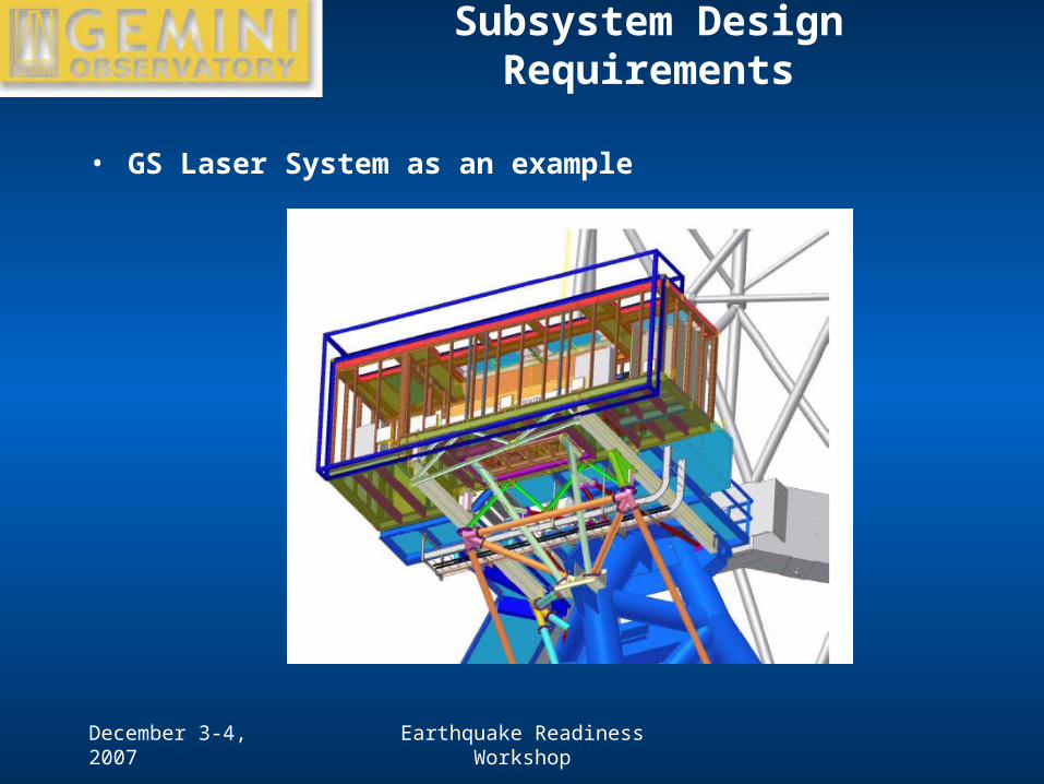
Subsystem Design Requirements
• GS Laser System as an example

December 3-4, 2007 Earthquake Readiness Workshop
Subsystem Design Requirements
Fragile Optics
Custom Optical Bench
Pneumatic Isolation System
Rigid Base Seismic restraint
Structural Features of the GS Laser System

December 3-4, 2007 Earthquake Readiness Workshop
Subsystem Design Requirements
Laser System Seismic Acceleration Input, X-Direction (horizontal, parallel to short dimension)
-25.00
-20.00
-15.00
-10.00
-5.00
0.00
5.00
10.00
15.00
20.00
25.00
0 5 10 15 20 25 30 35 40 45
Time (sec)
Acc
eler
atio
n (
m/s
^2)
December 3-4, 2007 Earthquake Readiness Workshop

December 3-4, 2007 Earthquake Readiness Workshop
Special Structural Features
• Seismic restraints– Limit excessive displacement or uplift– Subsystem must be able to withstand the restraint forces
• Seismic isolation– Allow the subsystem to break free in a controlled way– Restraint forces are small, but relative displacements are large– Can build in energy dissipation features into the isolation system
• Process– Identify fragile sub-systems– Assess Sub-system response in both Survival and Operational Seismic
Environments– Address the fragility level of the sub-system to the seismic response– Define the need for seismic restraints on these subsystems– Design these sub-system restraints

December 3-4, 2007 Earthquake Readiness Workshop
Gemini Seismic Restraints
M2 Followers
M1 Safety Restraint System
Seismic Restraints on Az and El axes

December 3-4, 2007 Earthquake Readiness Workshop
Gemini Seismic Restraints
Telescope Overturning Restraints

December 3-4, 2007 Earthquake Readiness Workshop
Gemini Seismic Restraints
• Primary Mirror Restraint System

December 3-4, 2007 Earthquake Readiness Workshop
Seismic Retrofit
• For the Gemini Observatory- – The seismic design features were based upon what we knew about the
seismic environment in Hawaii and Chile in the early 1990’s.
– Codes have been updated several times since then.
– Gemini intends to have an independent audit of our facilities to assess the need for retrofit in early 2008.