December 21, 2015 Mr. C. Pierce Regulatory Affairs Director
22
Mr. C. R. Pierce Regulatory Affairs Director , UNITED STATES NUCLEAR REGULATORY COMMISSION WASHINGTON, D.C. 20555-0001 December 21, 2015 Southern Nuclear Operating Company, Inc. Post Office Box 1295, Bin - 038 Birmingham, AL 35201-1295 SUBJECT: EDWIN I. HATCH NUCLEAR PLANT, UNIT 2, ALTERNATIVE HNP-ISl-ALT- HDPE-01 FOR USE OF HIGH DENSITY POLYETHYLENE IN PLANT SERVICE WATER PIPING (TAC MF6712) Dear Mr. Pierce: By letter to the U.S. Nuclear Regulatory Commission (NRC}, dated September 19, 2014, as supplemented November 13, and November 24, 2014, January 23, February 19, March 5, September 3, and October 1, 2015, Southern Nuclear Operating Company, (SNC), proposed an alternative to certain requirements of the American Society of Mechanical Engineers Boiler and Pressure Vessel Code, Section XI, Article IWA-4221 (b) associated with requirements for class 3 plant service water (PSW) piping at,.Edwin I Hatch Nuclear Plant, Unit 2 (HNP-2). In its letter of September 19, 2014, SNC stated that this lnservice Inspection (ISi) Alternative is needed to support the planned replacement of buried PSW system steel piping in HNP-2, with high density polyethylene (HOPE) piping. SNC stated that, for this repair and replacement activity, Article IWA-4221 (b) requires the new replacement piping to meet the original Construction Code requirements for the PSW piping. The applicable Construction Code does not provide rules for the design, fabrication, installation, examination and testing of HOPE piping. SNC provided an Alternative Technical Requirements (ATR) document to identify pertinent technical requirements and conditions. SNC proposed its Alternative on the basis that the Alternative provides an acceptable level of quality and safety. The NRC staff has reviewed the proposed Alternative and concludes, as set forth in the enclosed safety evaluation, that SNC has adequately addressed the applicable regulatory requirements set forth in 1 O CFR 50.55a. Therefore, pursuant to 1 O CFR 50.55a(z)(1 ), the NRC staff authorizes the use of Alternative HNP ISl-ALT-HDPE-01, Versions 2 and 3, for the remaining operational life of the plant on the basis that it provides an acceptable level of quality and safety. All other ASME Code, Section XI requirements for which an alternative was not
Transcript of December 21, 2015 Mr. C. Pierce Regulatory Affairs Director

Mr. C. R. Pierce Regulatory Affairs Director
, UNITED STATES NUCLEAR REGULATORY COMMISSION
WASHINGTON, D.C. 20555-0001
December 21, 2015
Southern Nuclear Operating Company, Inc. Post Office Box 1295, Bin - 038 Birmingham, AL 35201-1295
SUBJECT: EDWIN I. HATCH NUCLEAR PLANT, UNIT 2, ALTERNATIVE HNP-ISl-ALTHDPE-01 FOR USE OF HIGH DENSITY POLYETHYLENE IN PLANT SERVICE WATER PIPING (TAC MF6712)
Dear Mr. Pierce:
By letter to the U.S. Nuclear Regulatory Commission (NRC}, dated September 19, 2014, as supplemented November 13, and November 24, 2014, January 23, February 19, March 5, September 3, and October 1, 2015, Southern Nuclear Operating Company, (SNC), proposed an alternative to certain requirements of the American Society of Mechanical Engineers Boiler and Pressure Vessel Code, Section XI, Article IWA-4221 (b) associated with requirements for class 3 plant service water (PSW) piping at,.Edwin I Hatch Nuclear Plant, Unit 2 (HNP-2).
In its letter of September 19, 2014, SNC stated that this lnservice Inspection (ISi) Alternative is needed to support the planned replacement of buried PSW system steel piping in HNP-2, with high density polyethylene (HOPE) piping. SNC stated that, for this repair and replacement activity, Article IWA-4221 (b) requires the new replacement piping to meet the original Construction Code requirements for the PSW piping. The applicable Construction Code does not provide rules for the design, fabrication, installation, examination and testing of HOPE piping. SNC provided an Alternative Technical Requirements (ATR) document to identify pertinent technical requirements and conditions. SNC proposed its Alternative on the basis that the Alternative provides an acceptable level of quality and safety.
The NRC staff has reviewed the proposed Alternative and concludes, as set forth in the enclosed safety evaluation, that SNC has adequately addressed the applicable regulatory requirements set forth in 1 O CFR 50.55a. Therefore, pursuant to 1 O CFR 50.55a(z)(1 ), the NRC staff authorizes the use of Alternative HNP ISl-ALT-HDPE-01, Versions 2 and 3, for the remaining operational life of the plant on the basis that it provides an acceptable level of quality and safety. All other ASME Code, Section XI requirements for which an alternative was not
C.R. Pierce - 2 -
specifically requested and approved remain applicable, including third-party review by the authorized nuclear lnservice Inspector.
Docket No. 50-366
Enclosure: Safety Evaluation
cc w/encl: Distribution via Listserv
Sincerely,
Michael T. Markley, Chief Plant Licensing Branch 11-1 Division of Operating Reactor Licensing Office of Nuclear Reactor Regulation

UNITED STATES NUCLEAR REGULATORY COMMISSION
WA~HINGTON, D.C. 20555-0001
SAFETY EVALUATION BY THE OFFICE OF NUCLEAR REACTOR REGULATION
ALTERNATIVE HNP-ISl-ALT-HDPE,,01, VERSIONS 2.0 AND 3.0
FOR USE OF HIGH DENSITY POLYETHYLENE PIPING IN PLANT SERVICE WATER
SOUTHERN NUCLEAR OPERATING COMPANY, INC.
1.0 INTRODUCTION
EDWIN I. HATCH NUCLEAR PLANT, UNIT 2
DOCKET NO. 50-366
· By letter dated September 19, 2014, as supplemented by letters dated November 13 and . November 24, 2014, January 23, February 19, March 5, September 3, and October 1, 2015, (References 1 - 7, and 14), Southern Nuclear Operating Company, (SNC, the licensee), ' proposed an alternative to certain requirements of the American Society of Mechanical .Engineers (ASME) Boiler and Pressure Vessel Code (Code), Section XI, Article IWA-4221 (b) associated with requirements for class 3 plant service water (PSW) piping systems at Edwin I. Hatch Nuclear Plant - Unit 2 (HNP-2).
Specifically, pursuant to Title 10 of the Code of Federal Regulations (1 O CFR) Part 50.55a(a)(3)(i), (now 50.55a(z)(1 )) SNC requested permanent replacement of PSW carbon steel buried piping from the Turbine Building isolation valve box to the Reactor Building with High Density Polyethylene (HOPE) piping on the basis that the alternative provides an acceptable level of quality and safety.
2.0 REGULA TORY REQUIREMENTS
Pursuant to 10 CFR 50.55a(g)(4), ASME Code Class 1, 2, and 3 components (including supports) shall meet the requirements, except the design and access provisions and the pre-service examination requirements set forth in the ASME Code, Sec,ion XI, to the extent practical within the limitations of design, geometry, and materials of construction of the components.
1 O CFR 50.55a(z)(1) states, in part, that alternatives to the requirements of paragraph (g) of. 10 CFR 50.55a may be used, when authorized by the U.S. Nuclear Regulatory Commission (NRG), if the licensee demonstrates that (i) the proposed alternatives would provide an acceptable level of quality and safety or (ii) compliance with the specified requirements would result in hardship or unusual difficulty without a compensating increase in the level of quality · and safety.
Enclosure

- 2 -
3.0 TECHNICAL EVALUATION
3.1 Licensee's Proposed Alternative
3.1.1 Affected Components
The scope of this design change and modification is to replace approximately 1000 feet of the buried 10 inch carbon steel Unit 2 Division II PSW piping between valve 2P41-F3808 and the Unit 2 Reactor Building with HOPE piping of approximately 1225 feet in length. The run of the HOPE piping is different from the original run of carbon steel piping which accounts for the difference in pipe run lengths. Sections of the existing carbon steel piping, not required to be removed to facilitate installation of the HOPE piping, will be retired-in-place.
3.1.2 Applicable Code Requirements
The PSW piping is classified as seismic category I nuclear ASME class 3 piping. The Code of Record for the Fourth lnservice Inspection Interval, which ends December 31, 2015, is ASME Section XI, 2001 Edition through the 2003 addenda. The licensee will enter their Fifth lnservice Inspection (ISi) Interval on January 1, 2016, and the Code of Record will be the 2007 Edition, through the 2008 Addenda. ASME Code, Section XI, IWA-4221 (b) requires that "[an] item to be used for repair/replacement activities shall meet the Construction Code specified in accordance with (1 ), (2), or (3)." ASME Section XI, IWA-4221 (b)(1) requires that "when replacing an existing item, the new item shall meet the ASME Section Ill Construction Code to which the original item was constructed."
The Construction Code of record for Class 3 PSW piping at HNP-2 is USA Standard Code USAS 831.7 Class Ill, 1969 Edition, which is a predecessor to ASME, Section Ill, Subsection ND. The use of HOPE piping in safety-related ASME applications is a relatively recent development (recently used by Catawba and Callaway alternative requests) and was not available in the 1960's or 1970's to meet the construction code. There are no provisions in ASME Section XI or in an approved Code Case for installing HOPE Piping as a replacement for carbon steel during a repair/replacement activity. Currently various ASME Code Committees, with participation by the NRC members, are developing a mandatory appendix for HOPE use in safety-related ASME Class 3 applications. Therefore, based on information from the previous alternatives for Callaway and Catawba, and the ASME's mandatory appendix for HOPE in development along with NRC's comments communicated during ASME Code Committee meetings and ballot responses, the licensee prepared the requirements for HOPE to include Material .• Design and Analysis, Fabrication and Installation, Examinations and Tests, and lnservice Inspection and included this informatio·n in their submittal.
3.1.3 Proposed Alternative
The licensee proposes to replace existing carbon steel service water piping with HOPE piping. The licensee proposes to conduct this replacement in accordance with References 1 - 7, and Reference 14. ·
The implementation of HOPE piping will be performed during the fourth and fifth ISi intervals. This ISi Alternative applies to replacement of the licensee's Unit 2 Division fl PSW carbon steel
- 3 -
supply piping, from the Turbine Building isolation valve box to a new below-grade vault outside the Reactor Building, with HOPE piping produced with PE4710 material of cell classification 445574C with an estimated 14 inch nominal diameter. Maximum operating temperature of the system is 97 degrees Fahrenheit (°F) and maximum operating pressure is 190 pounds per square inch gauge (psig). The licensee identified in Reference 2 that 190 psig corresponds to the maximum operating pressure in a no flow condition, which is not a normal operating condition for the system. The Design Temperature is 123 °F with a design pressure of 180 psig.
3.1 .4 Basis for Use
The Hatch PSW system was originally designed with unlined carbon steel· piping. Plant-specific and industry operating experience has shown that carbon steel piping is susceptible to fouling, corrosion, and microbiologically induced corrosion (MIC) when used in raw water service.
The use of corrosion-resistant steel piping provides added resistance to such conditions, but does not eliminate susceptibility. Alternatively, the use of internal linings or coatings in carbon steel piping provides resistance to such conditions. However, degradation of and/or damage to the linings and coatings can cause exposure of the carbon steel piping to the raw water, resulting in piping degradation. Additionally, the linings and coatings can pose a potential foreign material concern, if they are released from the piping wall as a result of the degradation or damage.
The ASME Section Ill Construction Code and later editions and addenda of this Construction Code do not provide rules for the material, design, fabrication, installation, examination, and testing of piping constructed with HOPE material. The licensee has requested authorization to replace buried carbon steel piping in the PSW system with HOPE piping. The replacement will be in accordance with the requirements for HOPE piping as outlined in Enclosure 2 of Reference 1, as supplemented through Reference 7, and Reference 14.
Engineering calculations and analytical evaluations were performed by the licensee utilizing the requirements and design rules described in the design section of Reference 1, Enclosure 2, as supplemented through Reference 7 and in Reference 14.
The licensee proposes that, pursuant to 1 O CFR 50.55a(a)(3)(i), (now 50.55a(z)(1 )), in lieu of the requirement of Section XI, IWA-4221 (b)(1) for replacement of the PSW system piping, an alternative to the original Construction Code which provides an acceptable level of quality and safety for repair and replacement activities for ASME Class 3 buried piping be approved.
3.2 NRC Staff Evaluation
3.2.1 Qualification, Testing, Examination, and Quality Control
The acceptability tot.he NRC staff of the proposed alternative is based on five key points, outlined below.
1. The design and analysis of buried HOPE piping and its interface connections meet the applicable acceptance criteria establishing structural integrity for the various load combinations under normal, upset, emergency, faulted, and test conditions.

- 4 -
2. A reasonable assurance of leak tightness and structural integrity of the piping at installation will be provided by high quality and confirmatory testing of materials, fabrication, installation and testing of the piping system, as outlined in References 1 through 7, and 14. This includes parameters for fusion procedure qualification, fusion operator qualification, qualification of examination personnel, non-destructive examination (NOE) procedure qualification and plans for future testing.
3. HOPE piping is not susceptible to corrosion, fouling, rusting or MIC. The use of HOPE piping in raw water applications will thus ensure long-term structural integrity and water flow reliability.
4. All piping is buried, or tie-in locations will be contained in a vault with only one train or division contained within the vault. This adequately protects the piping from fire concerns.
5. Long-term integrity of the piping will be ensured by an isolated pressure decay test performed at least once each ISi interval. This will confirm absence of slow crack growth and other gross defects in the piping.
The ASME Code, Sections Ill and XI, predominately address metal piping, vessels, and components. The metal piping commonly used to hold and transport raw or service water in nuclear power plants is susceptible to corrosion, fouling, rusting, and MIC attacks. To mitigate these degradation mechanisms, a few licensees of nuclear power plants have selectively installed HOPE piping in non-safety and safety-related.applications. To date, the HOPE piping applications have had favorable operating experience regarding these degradation mechanisms. The industry's experience indicates that selected ASME Code Class 3 water carrying systems would be suitable. for HOPE piping as an alternative to the current metal piping.
The licensee is relying on the process described in Reference 1, "Alternative Technical Requirements (ATR)", as updated in Reference 7, in-house destructive and nondestructive testing, and preservice pressure testing to assure quality of the HOPE piping. The licensee will butt-fuse HOPE pipe joints onsite using performance-based qualified procedures, equipment, and personnel. The fusing process reviewed by the NAC staff covered qualifications, testing, examinations, and some aspects of quality control.
Although parts of the submittal referenced ASME Mandatory Appendix XXVI, "Rules for Construction of Class 3 Buried Polyethylene Pressure Piping," the NRC staff has based its conclusions on the engineering information provided by SNC as described in its proposed alternative.
3.2.1.1 Fusion Procedure and Equipment Qualification
As outlined in the ATR, SNC is using type PE4710 (cell classification 445574C) polyethylene material that is produced from a single batch of Dow Chemical DGDA-2492 resin, to the extent practical, with a minimum Pennsylvania Edge-Notch Test rating of 2,000 hours. SNC will be responsible for surveying, qualifying and auditing polyethylene material organizations to verify that the organizations quality assurance (QA) program conforms to the ATR and to SNC's QA

- 5 -
program requirements. The· personnel and equipment contracted by SNC for testing will be under-SNC's 10 CFR 50, Appendix B program. HOPE piping items will include straight pipe, fabricated mitered elbow and flange adapters. All HOPE-to-HOPE connections will be made using the butt thermal fusion process and the licensee's Fusing Procedure Specifications found in the ATR. All material will be tested for fusibility using the fusing procedures in accordance with Section 2300 of the ATR. All joint testing will use the same fusing machine make and carriage model to be used for joining the materials in production. Testing of the specimens will be performed by High Speed Tensile Impact Test and Guided Side~bend Testing. The purpose of using both tests is to ensure that the fusion joints exhibit ductile fracture, which is considered acceptable and not brittle fracture, which is a rejectable condition.
The fusion procedure contains the essential variables necessary to make an acceptable joint and the "how to" process of fabricating the joint. The fusion procedure is specific to material, fusion process, configuration {elbow, pipe, diameter range, wall thickness range), equipment, and essential variables. Essential variables affecting joint integrity are identified in Enclosure 2, Table 3-254 of Reference 1, including material batch lot, product form, manufacturing facility, nominal diameter, nominal thickness, fusing carriage make and model, machine slope exceeding 20 degrees, and fusing ambient temperature is less than 50 °F or greater than 125 °F. The NRC staff has reviewed SNC's proposal and considers these to be the correct essential variables for fusing HOPE to ensure .that the procedure will result in good quality fused joints.
The licensee has proposed a method to verify fusibility, as outlined below. The licensee's approach is to make one square butt-joint at each of the following conditions to verify fusibility at the pressure/temperature extremes of the fusing procedure, i.e., ''fusing the box":
• lhterfacial pressure of 90 psi minimum and heater temperature of 450 °F minimum; heater removal (dwell time) kept to a minimum (must not exceed the specified maximum)
• lnterfacial pressure of 60 psi maximum and heater temperature of 450 °F minimum; heater removal (dwell time) kept to a minimum (must not exceed the specified maximum) '
• lnterfacial pressure of 90 psi minimum and heater temperature of 400 °F maximum; heater removal (dwell time) at the maximum permitted
• lnterfacial pressure of 60 psi maximum and heater temperature of 400 °F maximum; heater removal (dwell time) at the maximum permitted
In addition to the above, the licensee states that precautions will be taken to prevent contamination of the joint during the fusing process by protecting the piping to prevent all deleterious contamination during fusing operations. Fusing shall not be performed on wet surfaces or surfaces containing dust or fine particulate. Items to be jointed will be fitted, faced, aligned and retained in position during the fusing operation. The alignment surface mismatch will be less than 10% minimum fabricated wall thickness {tfab min) of the items being fused. A data acquisition device will be used for each joint fusion to enswe that the proper fusing parameters and procedures were followed for each joint.
The licensee's qualification process for the fusion procedure consists of demonstrating capability, reliability, and effectiveness. To show capability, the licensee will use the essential

- 6 -
variable group extremes to produce joints at each corner of the "box". To show reliability, the licensee will be using single batch material from one resin manufacturer. To show effectiveness, the licensee will subject each joint to a minimum of four High Speed Tensile Impact Tests and four Guided Side Bend Tests with each test taken approximately 90-degrees apart around the circumference.
Based on the above, the NRC staff concludes that the licensee's process for demonstrating the capability, reliability, and joint effectiveness to qualify the fabrication procedure is acceptable.
3.2.1.2 Fusion Operator Qualification
The licensee, or its approved Certificate Holder, will conduct the tests (equired by the ATR to qualify the performance of fusing operators who apply the fusing procedures. Each fusing machine operator will receive a minimum of 24 hours of training covering the principles of the fusion process and the operation of the fusing equipment. The make and model of each fusing machine carriage to be used in production will be tested in accordance with Section 2300 of the ATR on the diameters and thickness that will be used and each fusing operator will be qualified on these same machines. The qualification testing will consist of cutting material from the test joint and performing Reverse Bend tests or Guided Side bend test. As part of test preparation, the specimens are visually examined for evidence of voids and discontinuities, and the data acquisition record will be reviewed to verify conformance with the fusing procedure specification. The making of fused joints using representative material, pipe diameter, and wall thicknesses, and the examination and testing of the joints demonstrate the fusion operator's ability to follow the fusion procedure and make acceptable joints. Based on the above, the NRC staff concluded that the demonstration used by the licensee to qualify fusion operators is acceptable.
3.2.1.3 Qualification of Examination Personnel
The licensee will provide a minimum of 24 hours of training to certify qualified VT-1 (visual examination) personnel for reviewing recorded fusion joining data and performing bead-app~arance examinations. The licensee will give VT-1 personnel hands-on practice in operating HOPE fabrication equipment and in making fused butt joints. The VT-1 personnel must successfully pass a licensee-administered performance demonstration consisting of a combination of acceptable and unacceptable fused joints. A sample set with flaws representative of unacceptable conditions will be used. The written visual examination procedure will be used and a passing grade of 80% detection of the intended flaw will be required for qualification for VT-1 visual inspection of the piping.
Volumetric examination personnel will demonstrate their capability to detect flaws using, the qualified procedure in a blind performance demonstration conducted on a specimen set containing surface-connected and subsurface flaws. Detection of 80% of the intended flaws in the performance demonstration test set is required to qualify for ultrasonic testing (UT) examination of HOPE fused joints. All personnel qualification will be in accordance with Section 5000 of the ATR.
Based on the above, the NRC staff concludes that personnel successfully demonstrating their skills on representative mockups of acceptable and rejectable fused joints assures their proficiency and is, therefore, acceptable. ·

- 7 -
3,2.1.4 ·aualification of Volumetric Examination Procedures
Written UT examination procedures will be qualified in accordance with Section 5000 of the ATR by performance demonstration testing, with Supplement 2 of the ATR providing further specifications. Demonstration testing will be witnessed by an Authorized Nuclear lnservice Inspector and also by an NRC representative. The demonstration test specimen for UT examinations will be fabricated from the same material being installed, will contain a joint that is representative of the joint to be examined (including the same fusing variables and parameters), and joint surfaces will be representative of the production surfaces to be examined (i.e. no deleterious contamination). The procedure demonstration will only be accepted if-100% of detectable flaws are identified.
The types of flaws included in the demonstration specimens are detailed in Section 5114 of the ATR. In a Request for Additional Information (RAI) response, dated January 23, 2015, the licensee details how the flawed specimens will be produced for demonstration. Surfaceconnected flaws will be produced using very thin cutting tools after the joint is fused. Plans for producing internal flaws will be refined as research performed by the Electric Power Research Institute (EPRI) provides techniques and quality control practices. In the case that this research is not completed by the time the licensee's test specimens need to be created, the specimens will be produced using existing trial and error methods to be verified using volumetric NOE such as double-angle radiography.
The acceptance criterion is that any unbonded area in the joint or indication of a flaw in the joint not attributable to configuration that is detected with UT is rejected. Based on the above, the NRC staff concludes that the performance demonstration provides verification of personnel skills and procedure effectiveness in detecting volumetric flaws and is, therefore, acceptable.
3.2.1.5 Testing Examinations
The visual examiner will perform a VT-1 examination on the outer diameter of the fusion joint bead and verify that the recorded data in the data logger is within the fusion procedure pressure and fusion time ranges. The UT examiner will use a UT examination to verify an absence of volumetric flaws in the joint region (a portion of the pipe end and the fused joint). Based on the above, the NRC staff concludes that the examinations for verifying joint integrity should detect detrimental flaws, if any, in the joint region and are, therefore, acceptable.
3.2.1.6 Process Control Criteria
The licensee will be recording essential variables with a data logger during the fusion process. The data being recorded is viewed by the fusion operator. The recorded data from the data logger (pressure and fusion time) are reviewed for acceptance befqre the licensee buries the joint. If any variables deviate outside the acceptable ranges, the joint is cut out. A sampling of butt fusion joints produced at the site will be removed and destructively tested to verify soundness. This. will include the first production joint each week on each fusing machine plus a representative sampling of additional butt fusion joints such that a minimum of 10% of the joints produced on each machine are tested. In addition to the process control, the fused joint will be
- 8 -
ultrasonically examined. The licensee will maintain the data logger information and inspection results. Based on the above, the NRC staff concludes that proposed process control is, therefore, acceptable.
3.2.1. 7 Pressure Testing
The licensee will perform a hydrostatic test at 1.5 times the system design pressure + 1 O psig. The piping will be examined for leakage by VT-2 qualified personnel. The hydrostatic test is effective in detecting existing though-wall flaws that cannot be detected by current UT technology. However, because HOPE material flows over time, the hydrostatic test gives little, if any, information on embedded flaws which may grow over time. System monitoring will be used to detect leakage after the piping is buried. Based on the above, the NRC staff concludes that the proposed pressure testing is, therefore, acceptable.
3.2.1.8 Future Testing
The use of HOPE pipe in ASME Code Class 3 piping systems is a relatively recent development for the U.S. nuclear power industry. To address unknown integrity issues that may appear after burying the piping, the licensee will perform- an isolated pressure decay test on the PSW system at least once each ISi Inspection interval for the remaining life of the plant. As stated in Reference 7, Supplement 5, this test will be at 1.1 times design pressure. Design pressure is defined in Reference 7 as 180 psig, thus resulting in a test pressure of 198 psig. This testing will ensure that the piping has maintained structural integrity and is fit for continued service. This is considered to _be within the scope of the requested alternative.
3.2.2 Structural Integrity and Design Evaluation
The licensee provided a detailed structural integrity evaluation of the buried HOPE PSW piping considering loadings that include internal pr'essure, soil and surcharge loads, 1 external pressure, seismic loads (seismic wave passage, seismic soil movement) induced from the Operational Basis Earthquake (QBE) and Design Basis Earthquake (DBE), and thermal expansion and contraction, seismic anchor movements (OBE & DBE), and soil settlement. In addition to the design truck loads, surcharge loads for an Independent spent fuel storage
_Installation cask transporter were also considered. The NRC structural evaluation review includes pressure design of HOPE joints and fittings, ring deflection of HOPE from soil and surcharge loads, compressive stresses in HOPE side walls, buckling due to external pressure, evaluation for flotation effects, primary stress evaluation for levels A, B, & D from internal pressure and seismic loading, and secondary stress evaluations. Service level C is not evaluated because the loads and stress allowables are the same as for service level D.
3.2.2.1 Hoop Stresses from Internal Pressure
The design, normal, maximum operating, and test pressures and temperatures for the PSW piping are summarized below. The material for HOPE is PE471 O with material properties of cell classification 44557 4C. The corresponding circumferential or hoop stresses in 14 inch
1 Surcharge load is moving load on buried pipe such as vehicular traffic on the road above the buried pipe.
- 9 -
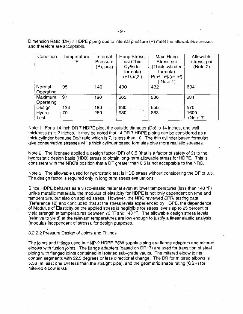
Dimension Ratio (DR) 7 HOPE piping due to internal pressure (P) meet the allowables stresses, and therefore are acceptable.
Condition Temperature Internal Hoop Stress, Max. Hoop Allowable Of Pressure psi (Thin Stress psi stress, psi
(P), psig Cylinder (Thick cylinder (Note 2) formula) formula) (PDo)/(2t) P(a2+b2)/(a2-b2)
(Note 1) Normal 95 140 490 432 694 Operating Maximum 97 190 665 586 684 Operating Desiqn 123 180 630 555 570 Hydro 70 280 980 863 1600 Test {Note 3)
Note 1: For a 14 inch DR 7 HOPE pipe, the outside diameter (Do) is 14 inches, and wall thickness (t) is 2 iriches. It may be noted that 14 DR 7 HOPE piping can be considered as a thick cylinder because Dolt ratio which is 7, is less than 10. The thin cylinder bqsed formulas give conservative stresses while thick cylinder based formulas give more realistic stresses.
Note 2: The licensee applied a design factor (OF) of 0.5 (that is a factor of safety of 2) to the hydrostatic design basis (HOB) stress to obtain long-term allowable stress for HOPE. This is consistent with the NRG's position that a DF greater than 0.5 is not acceptable to the NRG.
Note 3. The allowable used for hydrostatic test is HOB stress without considering the DF of 0.5. The,design factor is required only in long term stress evaluations.
Since HOPE behaves as a visco-elastic material even at lower temperatures (less than 140 °F) unlike metallic materials, the modulus of elasticity for HOPE is not only dependent on time and temperature, but also on applied stress. However, the NRG reviewed EPRI testing data (Reference 12) and concluded that at the stress levels experienced by HOPE, the dependence of Modulus of Elasticity on the applied stress is negligible for stress levels up to 25 percent of yield strength at temperatures between 73 °F and 140 °F. The allowable design stress levels (relative to yield) at the relevc:i.nt temperatures are low enough to justify a linear elastic analysis (modulus independent of stress), for design purposes.
;3.2.2.2 Pressure Design of Joints and Fittings
The joints and fittings used in HNP-2 HOPE PSW supply piping are flange adapters and mitered elbows with fusion joints. The flange adapters (based on DR=7) are used for transition of steel piping with flanged joints contained in isolated sub-grade vaults. The mitered elbow joints contain segments with 22.5 degrees or less directional change. The DR for mitered elbows is 5.33 (at least one DR less than the straight pipe), and the geometric shape rating (GSR) for mitered elbow is 0.8.

- 10 -
Component Design Pressure (psi). GSR Pressure Rating (psi) (PR=GSR (2S/(DR-1)
Flange Adapters 180 1.0 190 Miter Elbows 180 0.8 210
The licensee has demonstrated that the design pressure is less than the pressure rating applying the appropriate GSR factors, and, therefore, the NRC staff concludes that the fittings are acceptable.
3.2.2.3 Ring Deflection
The soil and surcharge loads on buried HOPE pipe cause ring deflection of pipe diameter. The calculated ring deflection expressed as a ratio of percentage of change in diameter to the original diameter [100 (b.D/D)] is demonstrated to be less than the allowable ring deflection, and therefore is acceptable. For DR7 piping the allowable ring defledion is 2.8%.
Deflection Deflection
3.2.2.4 Sidewall Compression
The soil and surcharge loads on buried HOPE pipe induce circumferential compressive stresses in the sidewalls. These stresses are calculated and shown to be less than the corresponding allowable stress as summarized in table below, and, therefore, are acceptable.
Calculated Sidewall Circumferential Compressive stress si 145
3.2.2.5 Buckling
Allowable Sidewall Circumferential Com ressive Stress 630
Si
The external pressure from soil and surcharge loads, flooding, and ground water surrounding the buried HOPE pipe induces circumferential compressive stresses and can lead to buckling. The licensee has demonstrated t.hat the calculated external pressure is below the allowable limit to cause buckling, and therefore is acceptable as summarized in the table below.
Calculated total External External Pressure Limit for Pressure, (psi) Buckling (psi)
45 ( for < 4 feet cover) 169 17 (_for > 4 feet cover) ~ 54
J
- 11 -
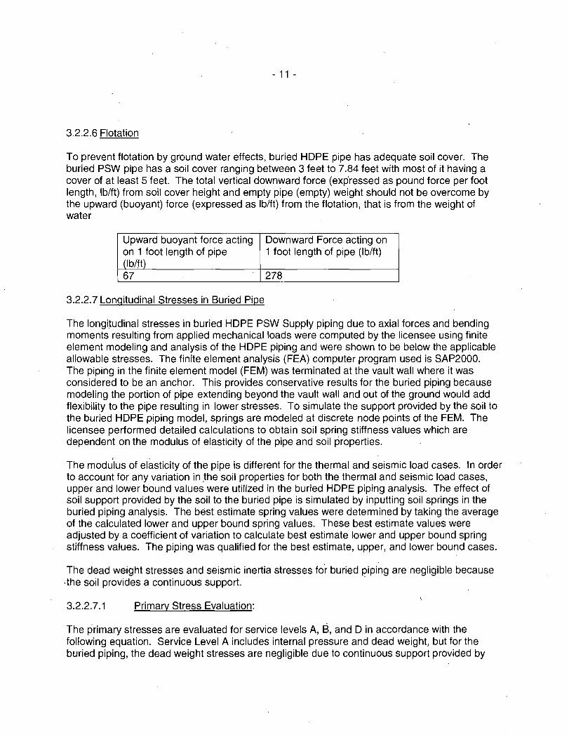
3.2.2.6 Flotation
To prevent flotation by ground water effects, buried HOPE pipe has adequate soil cover. The buried PSW pipe has a soil cover ranging between 3 feet to 7.84 feet with most of it having a cover of at least 5 feet. The total vertical downward force (expressed as pound force per foot length, lb/ft) from soil cover height and empty pipe (empty) weight should not be overcome by the upward (buoyant) force (expressed as lb/ft) from the flotation, that is from the weight of water
Upward buoyant force acting Downward Force acting on on 1 foot length of pipe 1 foot length of pipe (lb/ft) (lb/ft) 67 278
3.2.2.7 Longitudinal Stresses in Buried Pipe
The longitudinal stresses in buried HOPE PSW Supply piping due to axial forces and bending moments resulting from applied mechanical loads were computed by the licensee using finite element modeling and analysis of the HOPE piping and were shown to be below the applicable allowable stresses. The finite element analysis (FEA) computer program used is SAP2000. The piping in the finite element model (FEM) was terminated at the vault wall where it was considered to be an anchor. This provides conservative results for the buried piping because modeling the portion of pipe extending beyond the vault wall and out of the ground would add flexibility to the pipe resulting in lower stresses. To simulate the support provided by the soil to the buried HOPE piping model, springs are modeled at discrete node points of the FEM. The licensee performed detailed calculations to obtain soil spring stiffness values which are dependent on the modulus of elasticity of the pipe and soil properties.
The modu'lus of elasticity of the pipe is different for the thermal and seismic load cases. In order to account for any variation in ,the soil properties for both the thermal and seismic load cases, upper and lower bound values were utilized in the buried HOPE piping analysis. The effect of soil support provided by the soil to the buried pipe is simulated by inputting soil springs in the buried piping analysis. The best estimate spring values were determined by taking the average of the calculated lower and upper bound spring values. These best estimate values were adjusted by a coefficient of variation to calculate best estimate lower and upper bound spring stiffness values. The piping was qualified for the best estimate, upper, and lower bound cases.
The dead weight stresses and seismic inertia stresses fo·r buried piping are negligible because ·the soil provides a continuous support. ·
3.2.2.7.1 Primary Stress Evaluation:
The primary stresses are evaluated for service levels A, B, and D in accordance with the following equation. Service Level A includes internal pressure and dead weight, but for the buried piping, the dead weight stresses are negligible due to continuous support provided by
- 12 -
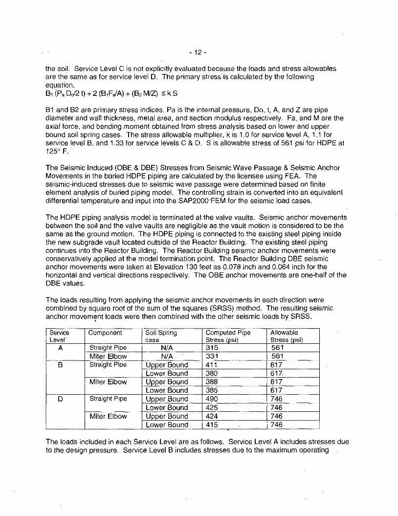
the soil. Service Level C is not explicitly evaluated because the loads and stress allowables are the same as for service level D. The primary stress is calculated by the following equation. 81 (Pa DJ2 t) + 2 (81FJA) + (82 M/Z) :s; k S
B 1 and B2 are primary stress indices, Pa is the internal pressure, Do, t, A, and Z are pipe diameter and wall thickness, metal area, and section modulus respectively. Fa, and M are the axial force, and bending moment obtained from stress analysis based on lower and upper bound soil spring cases. The stress allowable multiplier, k is 1.0 for service level A, 1.1 for service level B, and 1.33 for service levels C & D. S is allowable stress of 561 psi for HOPE at 125° F.
The Seismic Induced (OBE & DBE) Stresses from Seismic Wave Passage & Seismic Anchor Movements in the buried HOPE piping are calculated by the licensee using FEA. The seismic-induced stresses due to seismic wave passage were determined based on finite element analysis of buried piping model. The controlling strain is converted into an equivalent differential temperature and input into the SAP2000 ·FEM for the seismic load cases.
The HOPE piping analysis model is terminated at the valve vaults. Seismic anchor movements between the soil and the valve vaults are negligible as the vault motion is considered to be the same as the ground motion. The HOPE piping is connected to the existing steel piping inside the new subgrade vault located outside of the Reactor Building. The existing steel piping continues into the Reactor Building. The Reactor Building seismic anchor movements were conservatively applied at the model termination point. The Reactor Building DBE seismic anchor movements were taken at Elevation 130 feet as 0.078 inch and 0.064 inch for the horizontal and vertical directions respectively. The OBE anchor movements are one-half of the DBE values.
The loads resulting from applying the seismic anchor movements in each direction were combined by square root of the sum of the squares (SRSS) method. The resulting seismic anchor movement loads were then combined with the other seismic loads by SASS. . .
Service Component Soil Spring Computed Pipe Allowable Level· case Stress (psi) Stress (psi)
A Straight Pipe N/A 315 561 Miter Elbow N/A 331 561
B Straight Pipe Upper Bound 411 617 Lower Bound 380 617
Miter Elbow Upper Bound 388 617 Lower Bound 385 617
D Straight Pipe Upper Bound 490 746 Lower Bound 425 746
Miter Elbow Upper Bound 424 746 Lower Bound 415 746 .
The loads included in each Service Level are as follows. Service Level A includes stresses due to the design pressure. Service Level B includes stresses due to the maximum operating

- 13 -
pressure and forces and moments due to the effects of QBE seismic wave passage, QBE · seismic soil movement, and QBE seismic anchor movements. Service Level D includes stresses due to the maximum operating pressure and forces and moments due to the effects of DBE seismic wave passage, DBE seismic soil movement, and DBE seismic anchor movements. The NRC staff reviewed the results and concludes that they are acceptable because the computed stresses are less than the allowable limit values.
3.2.2.7.2 Secondary Stress Evaluation
A detailed evaluation of the secondary stresses from seismic, thermal expansion, and non-repeated anchor movements in the buried HOPE piping was performed by the licensee as summarized in the following sections. -
Seismic-Induced Stresses treated as secondary stresses
The secondary stresses from seismic wave passage and seismic anchor motion for the DBE are calculated by the following equation,
where i is stress intensification factor, FaE, and ME are axial force and bending moment from seismic wave passage, seismic anchor movement, A & Z are metal area and section modulus of the pipe, and SA is the fatigue allowable stress of 2032 psi for HOPE between 1000 and 10,000 cycles
The same forces and moments obtained from FEA for the DBE case were used to calculate the stress values summarized in the table below.
Component Soil Spring Load Calculated Allowable Stress Case Pipe Stress Range (psi)
(osi) Upper Bound 315 2032
Straight Pipe Lower Bound 185 2032
Upper Bound 139 2032 Miter Elbow
Lower Bound 128 2032
The NRC staff reviewed the results and finds them acceptable because the computed seismic DBE stresses meet the allowable limit. The QBE stresses are also acceptable because the allowable limit is unchanged while the QBE stresses are one half of the DBE stresses.
Combined Thermal Expansion and Contraction Stresses
The secondary stresses due to thermal contraction are based on a minimum water temperature of 32°F. The thermal stresses due to thermal expansion are based on the design temperature

- 14 -
of 123°F. This is conservative since the normal operating temperature and maximum operating temperature are only 95°F and 97°F respectively. Both cases utilize a ground temperature of 70°F. The allowable stress value was based on a temperature of 125°F instead of the design temperature of 123°F and, therefore, slightly conservative. The absolute values of stress due to thermal contraction and the stress due to thermal expansion are added to obtain thermal range stress.
The stress resulting from the assumption of fully constrained thermal contraction a re of th~ buried pipe when Twater < Tground, includes the stress due to axial contraction from Poisson's effect, and was determined as follows:
a re =./Epipea11T-v P0/(2 t) I
Here, Ep;pe is modulus of elasticity, a is coefficient of thermal expansion, fl. T is temperature difference, and vis Poisson's ratio for HOPE material. ·
The stress resulting from the assumption of fully constrained thermal expansion of the buried pipe a re when T water > T ground, was determined as follows:
a re= I Epipe a 11TI
The secondary stresses calculated by the following equation are summarized in the table below.
The thermal range stress is compared with the allowable stress range, SA of 2032 psi, and is acceptable because it meets the applicable limit.
/a re/+ /a re / $ SA
Stress Due to Stress Due Combined Allowable Thermal to Thermal range Stress Stress
Contraction Expansion (psi) Range (psi) (psi) a re (psi)
439 202 641 2032
Alternative Thermal Expansion and Contraction Evaluation
The secondary stresses from thermal expansion-contraction are .calculated by the following equation based on the forces and moments obtained from FEA.
iMJZ + FaJA $SA
where, Fae and Mc are axial force ·and bending moment from thermal expansion I contraction, and the rest of the symbols were the same as defined before.

- 15 -
Two separate thermal load cases with temperature values of 32°F and 123°F as input to the FEM as temperature changes of -38°F (= 32°F - 70°F) and +53°F (= 123°F - 70°F). The resulting loads for the two thermal load cases were then combined by absolute sum to obtain the thermal range response. The table below summarizes the bounding thermal range stresses for the thermal expansion and contraction load cases. The thermal range stresses in HOPE piping are below the allowable stress and, therefore, are acceptable. ·
Soil Spring Load Calculated Pipe Allowable Stress Component Case Stress (psi) Range (psi)
Upper Bound 588 2032 Straight Pipe Lower Bound 742 2032
Upper Bound 785 2032 Miter Elbow Lower Bound 985 2032
Non-Repeating Anchor Movements
The secondary stresses due to vault settlement calculated by the following equation,
iMo/Z + Fao/A :s; 2S
' where, Fao and Mo are axial force and bending moment from settlement and the rest of the symbols were the same as defined before.
The licensee performed calculations and determined that there is no potential for vault settlement. The licensee calculated vault heaving displacement of less than 1/8 inch for the new valve vault. Therefore, at the new valve vault support, the licensee applied a worst case upward displacement of 1/8 inch to the SAP2000 finite element models considering lower and upper bound spring stiffness values. The non-repeating anchor movement stress evaluations considered the worst case axial loads in combination with the worst case bending moments and are summarized in the following table.
Component Pipe Stress (psi) Long Term Allowable Stress (psi)
Straiqht Pipe 123 1122 Miter Elbow 38 1122
Based on a review of the computed stress due to1/8 inch building settlement, the NRC finds the stresses are acceptable because they meet the applicable allowable stress limit.
3.2.2.7.3 Interface
The stress analysis model for the buried HDPE piping in the yard from the existing subgrade vault (near Turbine Building) to the new subgrade vault (near Reactor Building) is documented in stress analysis calculation SMSH-14-011 and is terminated using fictitious anchors at the new supports inside both of the valve vaults. The stress analyses for the piping inside the valve vaults, stress

- 16 -
analysis calculation SMSH-15-001 (near the new vault), and stress analysis calculation SMSH-15-002 (near existing vault), included a portion of the buried HOPE piping from calculation SMSH-14-011 as overlap to address the interface. The modeling of fictitious anchors at the new· supports inside both of the valve vaults is considered conservative since flexibility of the piping inside the vaults are ignored. Further, the licensee validated the fictitious anchor modeling as being conservative by comparing the controlling loads from the soil supported piping analyzed in SMSH-14-011. to those resulting from the overlapped models within calculations SMSH-15-001 and SMSH-15-002. The controlling loads in SMSH-14-011 were larger than those in SMSH-15-001 and SMSH-15-002 with the exception of the loads resulting from the non-repeated anchor movement applied in the new vault (for vault heaving). The larger non-repeated anchor movement loads from SMSH-15-001 are acceptable because of substantial margin available as can be observed in section 5.7.2.4 for SMSH-14-011 calculation for non-repeating anchor movements.
The licensee performed detailed evaluations as documented in Enclosure 7 of Reference 14 to determine the impact of changes associated with the relocation of valve 2P41-F3808 and its operator in the existing Unit 2 Division II vault, and the addition of new stainless steel piping on the inside vault piping stress analysis models and the qualification of valves and pipe supports in the vicinity of the metallic and HOPE piping interface. These evaluations have demonstrated that the HOPE piping stresses and the metallic piping stresses (normal, upset, emergency, and faulted as well as seismic induced and thermal expansion I contraction stresses) are within the respective allowable limits. The interface flanges are designed for the loadings from the stress analysis. Further, the DBE accelerations of 0.324g and 0.291 g obtained from the analysis for the 12 inch and 2 inch stainless steel valves respectively are less than the acceptable limit of 4.5g. The licensee verified and determined the acceptability of the piping model terminations and overlap portions. Based on review of the licensee's evaluations, the NRC concludes that the piping interface considerations and evaluations are acceptable.
3.2.2.7.4 Moderate Energy Crack
The HNP-2 FSAR, Table 15A-1 defines moderate-energy piping systems as those having either a service pressure of greater than 275 psig or a service temperature of greater than 200°F. Piping systems outside containment whose service pressure is less than 275 psig and whose service temperature is less than 200°F are excluded from moderate energy crack postulation. The maximum operating and design pressures of the PSW system are less than 275 psig and the maximum operating and design temperatures are less than 200°F and therefore are excluded from moderate energy crack postulation. Therefore, the PSW piping is not identified for evaluation as a moderate-energy piping.
3.2.3 Fire Protection
In response to the NRC request regarding the fire hazard of the non-buried sections of the HOPE piping located in the existing service water vault 2B and the new service water vault and the impact on any safety-related commodities in the vicinity, the licensee provided the fire hazard information. The NRC staff also requested additional clarification regarding how safe shutdown capability is maintained it'the Unit 2 Division II PSW valve pit is flooded in the event that the HOPE piping failed due to fire. The licensee provided the requested .information as summarized below.
- 17 -
In Reference 6, the licensee stated that the PSW system consists of the ultimate heat sink (the Altamaha River) and two independent and redundant subsystems. Each of the two PSW subsystems is made up of a header, two 8500 gpm pumps, a suction source, valves, piping and associated instrumentation. For normal or emergency safe reactor shutdown either of the two subsystems is capable of providing the required cooling capacity to support the required systems with ·one pump operating. The two subsystems are separated from each other so failure of one subsystem will not affect the operability of the other system.
The licensee stated that if the Unit 2 Division II existing PSW valve pit were to flood and cause all the equipment within the pit to be inoperable, safe shutdown could still be achieved through safe shutdown path 1 because there is no safe shutdown path 1 equipment within the Unit 2 Division II existing PSW valve pit.
The licensee further stated that if there was a loss of inventory from the Unit 2 Division II piping being replaced with HOPE, adequate cooling flow is capable of being provided by the redundant PSW subsystem (safe shutdown path 1) to achieve safe shutdown. The loss of inventory from the Unit 2 Division II piping does not impact the ability for the redundant PSW subsystem to provide adequate cooling flow.
There are existing conduit runs between the Unit 2 Division II and Division I PSW valve pits. The Unit 2 Division I PSW valve pit contains safe shutdown path one equipment. The licensee
·stated that this design change will ensure these conduit runs are adequately sealed such that water from the Unit 2 Division II valve pit cannot reach the Unit 2 Division I valve pit to impact safe shutdown path one equipment.
The licensee indicated that both Unit 2 PSW valve pits currently have 6-inch curbs around their perimeters that are designed to prevent the entrance of liquid combustibles from a large spill of fuel oil truck. If the Unit 2 Division II PSW valve pit were to flood and overflow into the yard area, the existing 6-inch curb will prevent the water from entering the Unit 2 Division I PSW valve pit.
Therefore, the licensee concluded that if the new Unit 2 Division II PSW pit were to flood, safe shutdown could still be achieved through safe shutdown path 1 because there will be no safe shutdown path 1 equipment in the new Unit 2 Division II PSW pit. The loss of inventory of the Division II piping will not impact safe shutdown path one inventory, and there will be no pathways for flood water in the new Unit 2 Division II PSW pit to reach safe shutdown path 1 equipment where. it could potentially impact safe shutdown.
Based on the above, the NRC staff agrees that the boundaries of the fire areas and the safe shutdown capability in the event of a fire are adequate to ensure that a fire within either fire area · will not damage redundant systems from both shutdown paths and that a fire that originates outside these areas will n~t spread into these areas and damage vulnerable shutdown systems.
SNC provided the following statement in its design submittal, Reference 7, page E1-4, regarding protection of piping from the effects of fires.
- 18 -
Other facets of design, including but not limited to Appendix R fire protection, associated civil structural modifications, and excavation and backfill using a flowable fill cement mixture, will be addressed under SNC design procedures in accordance with the existing design and license basis for HNP. Also, there are existing conduit runs between the Unit 2 Division 11 and Division I PSW valve pits. The Unit 2 Division I PSW valve pit contains safe shutdown path 1 equipment; therefore, SNC will ensure that the conduit runs are adequately sealed such that water from the Unit 2 Division II valve pit cannot reach the Unit 2 Division I PSW . valve pit to impact safe shutdown path 1 equipment.
SNC's statement is within the scope of the Alternative being authorized by the NRC staff. Accordingly, the NRC staff concludes that the associated fire protection provisions for this Alternative have been resolved acceptably.
4.0 CONCLUSION
The NRC staff has reviewed the proposed Alternative and concludes, as set forth in this safety evaluation, that SNC has adequately addressed the applicable regulatory requirements set forth in 10 CFR 50.55a. Therefore, pursuant to 10 CFR 50.55a(z)(1) the NRC staff authorizes the use of Alternative HNP ISi-AL T-HDPE-01, Versions 2 and 3, for the remaining operational life of the plant on the basis that it will provide an acceptable level of quality and safety. All other ASME Code, Section XI requirements for which an alternative was not specifically requested and approved remain applicable, including third-party review by the Authorized Nuclear lnservice Inspector.
5.0 References
Letter No. NL-14-1250, from C.R. Pierce, Regulatory Affairs Director, SNC, to NRC, "Edwin I. Hatch Nuclear Plant - Unit 2, Proposed Inspection Alternative HNP-ISl-AL THDPE-01 Version 2.0," September 19, 2014. Contains 8 Enclosures (ADAMS No. ML 14266A183).
2. Letter No. NL-14-1821, from C. R. Pierce, Regulatory Affairs Director, SNC, to NRC, "Edwin I. Hatch Nuclear Plant Unit 2, Proposed Inspection Alternative HNP-ISl-ALTHDPE-01, Version 2.0, Supplemental Information," November 13, 2014. Contains 2 Enclosures (ADAMS No. ML 14317A261).
3. Letter No. NL-14-1876, from C.R. Pierce, Regulatory Affairs Director, SNC, to NRC, "Edwin I. Hatch Nuclear Plant - Unit 2, Proposed lnservice Inspection Alternative HNPISl-AL T- HDPE-01 version 2.0 Conceptual Design Information Package," November 24, 2014. Contains 5 Enclosures (ADAMS No. ML 15028A518). ·
4. Letter No. NL-15-0082, from C. R. Pierce, Regulatory Affairs Director, SNC, to NRC, "Edwin I. Hatch Nuclear Plant - Unit 2, Response to Request for Information Regarding Proposed lnservice Inspection Alternative HNP-ISl-AL T- HDPE-01, Version 2.0, January 23, 2015. Contains 2 Enclosures (ADAMS No. ML 15023A507).

- 19 -
5. Letter No. NL-15-0331, from C. R. Pierce, Regulatory Affairs Director, SNC, to NRC "Edwin I. Hatch Nuclear Plant - Unit 2, Response to Request for Additional Information from Mechanical and Civil Branch Regarding High Density Polyethylene (HOPE) Piping Replacement," February 19, 2015. Contains 2 Enclosures (ADAMS No. ML 15051A448).
6. Letter No. NL-15-0433, from C.R. Pierce, Regulatory Affairs Director, SNC, to NRC, "Edwin I. Hatch Nuclear Plant Unit 2, Supplemental Response to Request for Additional Information from Mechanical and Civil Branch Regarding High Density Polyethylene (HOPE) Piping Replacement RAl-13," March 5, 2015. Contains 1 Enclosure (ADAMS No. ML 15069A640).
7. Letter No. NL-15-1754, from C.R. Pierce, Regulatory Affairs Director, SNC, to NRC, "Edwin I. Hatch Nuclear Plant - Unit 2, Proposed lnservice Inspection Alternative HNPISl-AL T-HDPE-01, Version 3.0, October 1, 2015 (ADAMS No. ML 15274A197).
8. Hatch HNP-2 Final Safety Analysis Report, Revision 28, September 2010.
9. USA Code for Pressure Piping, USAS B31.7, 1969 Edition.
10 ASME Boiler and Pressure Vessel Code, Section XI, Rules for lnservice Inspection of Nuclear power Plant components, 2001 Edition through 2003 Addenda.
11. ASME Boiler and Pressure Vessel Code, Section XI, Rules for lnservice Inspection of Nuclear power Plant components, 2007 Edition through 2008 Addenda.
12. Tensile Stress-Strain Properties and Elastic Modulus of PE 4710 Cell Classification 445574C High Density Polyethylene Pipe Material, EPRI Report 1025254, December 2012.
13. Creep and Fatigue Properties of PE 4710 Cell Classification 44557 4C High Density Polyethylene Pipe Material, EPRI Report, 3002000592, November 2013.
14 Letter No. NL-15-1628, from C.R. Pierce, Regulatory Affairs Director, SNC, to NRC, "Edwin I. Hatch Nuclear Plant - Unit 2, Proposed Inspection Alternative HNP-ISl-AL THDPE-01 Version 2.0, Final Stress Analysis for the Design of the HOPE System," September 03, 2015, (ADAMS No. ML 15246A 156).
Principal Contributors: M. Audrain C. Basavaraju
Date: December 21, 2015

C.R. Pierce - 2 -
specifically requested and approved remain applicable, including third-party review by the authorized nuclear lnservice Inspector.
Docket No. 50-366
Enclosure: Safety Evaluation
Sincerely,
/RA/
Michael T. Markley, Chief Plant Licensing Branch 11-1 Division of Operating Reactor Licensing Office of Nuclear Reactor Regulation
cc w/encl: Distribution via Listserv
DISTRIBUTION: PUBLIC LPL2-1 R/F RidsNrrDorlLPL2-1 Resource RidsNrrLASFigueroa Resource RidsEdoMailCenter Resource RidsNrrDeEpnb Resource
RidsNrrPMHatch Resource RidsNrrDorlDpr Resource RidsACRS_MailCTR Resource RidsRgn2MailCenter Resource RidsNrrDeEmcb Resource
ADAMS Accession No. ML 15337A414 OFFICE NRR/LPL2-1/PM N RR/LPL2-1 /LA NAME BMartin SFigueroa DATE 12/18/15 12/07/15
OFFICE NRR/DE/EMCB/BC NRR/LPL2-1/BC NAME Tlupold MMarkley DATE 12/01/15 12/21/15
OFFICIAL RECORD COPY
DAiiey, DE CBasavarju, DE KManoly, DE Tlupold, DE MAudrain, DE
NRR/DE/EPNB/BC DAiiey 12/01/15
NRR/LPL2-1/PM BMartin 12/21/15