
December 2, 2015 USDA Forest Service Tongass Nat'l...
24
December 2, 2015 Brad Orr USDA Forest Service Tongass Nat'l Forest Juneau Ranger District 8510 Mendenhall Loop Road Juneau, AK 99801 RE: Kensington Gold Project 2016 Surface Exploration Work Plan Dear Mr. Orr: Coeur Alaska is pleased to submit the attached 2016 proposed surface exploration annual work plan. The work plan describes the proposed surface exploration program planned to be conducted in 2016 on lands administered by the Forest Service. Should you have any questions or require clarification regarding the document or on any other issue, please contact me at (907) 523-3328. Best regards, Kevin Eppers Environmental Manager Cc: Kyle Moselle, ADNR Coeur Alaska, Inc. 3031 Clinton Dr., Suite 202 Juneau, Alaska 99801 Telephone 907.523.3344 Facsimile 907.523.3330 www.KensingtonGold.com
-
Upload
nguyennguyet -
Category
Documents
-
view
215 -
download
0
Transcript of December 2, 2015 USDA Forest Service Tongass Nat'l...

December 2, 2015 Brad Orr USDA Forest Service Tongass Nat'l Forest Juneau Ranger District 8510 Mendenhall Loop Road Juneau, AK 99801 RE: Kensington Gold Project 2016 Surface Exploration Work Plan Dear Mr. Orr: Coeur Alaska is pleased to submit the attached 2016 proposed surface exploration annual work plan. The work plan describes the proposed surface exploration program planned to be conducted in 2016 on lands administered by the Forest Service. Should you have any questions or require clarification regarding the document or on any other issue, please contact me at (907) 523-3328. Best regards,
Kevin Eppers Environmental Manager Cc: Kyle Moselle, ADNR Coeur Alaska, Inc. 3031 Clinton Dr., Suite 202 Juneau, Alaska 99801 Telephone 907.523.3344 Facsimile 907.523.3330 www.KensingtonGold.com

!(
!(
!(
!(!(!(
!(!(
!(!(
!(!(
!(
!(
!(!(
!(!(!(!(!(
!(
!(!(!(!(
!(!(!(
!(!(!(!(
!(!(!(!(!(
!(!(!(!(!(!(!(
!(!(!(
!(!(!(!(
!(
!(!(
!(!(!(!(!(
!(
±
2016 Kensington Drill Pads USFS Application
Juneau Quadrangles D-3 and D-4NAD 1927
1 inch equals 0.5 miles
2016 Drill Pad Locations!( Ophir
!( Jualin
!( Comet
!( Fremming
0 0.5 10.25 Miles

COEUR ALASKA – KENSINGTON GOLD MINE
2016 SURFACE EXPLORATION ANNUAL WORK PLAN
Coeur Alaska plans to conduct a surface exploration program in 2016. These activities will occur on patented lode mining claims and adjacent federal and state lode mining claims. Exploration activities include detailed geologic mapping, ground surveying, geochemical sampling (rocks, soils, and stream silts), and ground‐based geophysics.
Diamond drill core drilling totaling roughly 30,000 feet is planned for several prospects. A
maximum of sixty‐one (61) sites will be utilized in 2016. Of the sixty‐one sites, thirty‐eight (38) of the proposed sites would be located on patented lode mining claims and twenty‐three (23) would be located on Forest Service lands. Small areas for the sites will need clearing for drill platforms and safe helicopter landing sites.
Support personnel, field geologists and drill crews will operate from the Kensington Camp and
port facility at Slate Cove. Helicopter support will be based in Juneau, Alaska and will be utilized for field geologist and drill crew transportation and drill moves. Surface activities could commence as early as April and continue through the end of December. Reconnaissance:
Helicopter‐supported reconnaissance‐style (1"=200' to 1"=1000' scale) geologic mapping may be conducted throughout the Kensington Mine area and the Tongass National Forest adjacent to the Kensington Mine area. These activities include geologists traversing the ground to and from existing roads and helicopter landing sites, which are often located on open ridges, creek bottoms, and meadows or muskegs. No new landing sites will be cleared, except near drill sites (as described below). Small rock, soil, and stream sediment samples are periodically collected for geochemical (assay) analysis and the sample sites are recorded with a handheld GPS unit and marked with biodegradable flagging. Prospect Work:
Geological and geochemical work is planned for the Kensington Mine area within patented and unpatented claims in the Tongass National Forest. Activities consist of line surveying with compass and tape, detailed geologic mapping, and geochemical sampling (rock, soil, and silt), and a possible ground‐based geophysical survey. Minimal disturbance of vegetation and/or topsoil layers may be necessary in areas where outcrop exposure is limited. Grid work will entail a minimal amount of brush and deadfall clearing to allow the safe ingress and egress of field personnel and hand carried equipment. There will be no cutting or falling of live trees and no disturbance of the topsoil during the line clearing work. The brushed cleared lines will be marked with biodegradable pink or orange flagging at 20 to 50 foot intervals. The soil geochemical sampling survey will require minimal top soil disturbance consisting of shallow holes excavated to a
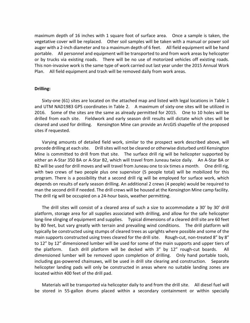
maximum depth of 16 inches with 1 square foot of surface area. Once a sample is taken, the vegetative cover will be replaced. Other soil samples will be taken with a manual or power soil auger with a 2‐inch diameter and to a maximum depth of 6 feet. All field equipment will be hand portable. All personnel and equipment will be transported to and from work areas by helicopter or by trucks via existing roads. There will be no use of motorized vehicles off existing roads. This non‐invasive work is the same type of work carried out last year under the 2015 Annual Work Plan. All field equipment and trash will be removed daily from work areas. Drilling:
Sixty‐one (61) sites are located on the attached map and listed with legal locations in Table 1 and UTM NAD1983 GPS coordinates in Table 2. A maximum of sixty‐one sites will be utilized in 2016. Some of the sites are the same as already permitted for 2015. One to 10 holes will be drilled from each site. Fieldwork and early season drill results will dictate which sites will be cleared and used for drilling. Kensington Mine can provide an ArcGIS shapefile of the proposed sites if requested.
Varying amounts of detailed field work, similar to the prospect work described above, will precede drilling at each site. Drill sites will not be cleared or otherwise disturbed until Kensington Mine is committed to drill from that site. The surface drill rig will be helicopter supported by either an A‐Star 350 BA or A‐Star B2, which will travel from Juneau twice daily. An A‐Star BA or B2 will be used for drill moves and will travel from Juneau one to six times a month. One drill rig, with two crews of two people plus one supervisor (5 people total) will be mobilized for this program. There is a possibility that a second drill rig will be employed for surface work, which depends on results of early season drilling. An additional 2 crews (4 people) would be required to man the second drill if needed. The drill crews will be housed at the Kensington Mine camp facility. The drill rig will be occupied on a 24‐hour basis, weather permitting.
The drill sites will consist of a cleared area of such a size to accommodate a 30’ by 30’ drill platform, storage area for all supplies associated with drilling, and allow for the safe helicopter long‐line slinging of equipment and supplies. Typical dimensions of a cleared drill site are 60 feet by 80 feet, but vary greatly with terrain and prevailing wind conditions. The drill platform will typically be constructed using stumps of cleared trees as uprights where possible and some of the main supports constructed using trees cleared for the drill site. Rough‐cut, non‐treated 8” by 8” to 12” by 12” dimensioned lumber will be used for some of the main supports and upper tiers of the platform. Each drill platform will be decked with 3” by 12” rough‐cut boards. All dimensioned lumber will be removed upon completion of drilling. Only hand portable tools, including gas‐powered chainsaws, will be used in drill site clearing and construction. Separate helicopter landing pads will only be constructed in areas where no suitable landing zones are located within 400 feet of the drill pad.
Materials will be transported via helicopter daily to and from the drill site. All diesel fuel will be stored in 55‐gallon drums placed within a secondary containment or within specially

constructed double walled aluminum tanks. Both are capable of holding 110% of the primary volume. All drilling materials that may attract bears (drilling fluids, etc.) will be kept to a minimum at the drill site and also will be stored in secondary containment and/or over the primary sump. Domestic waste will be removed twice daily, at the end of each shift.
The drill contractor will be required to complete an environmental pre‐shift checklist on the drill and water supply pump sites prior to each shift. The environmental pre‐shift checklist, shown in Appendix 1, provides a system for the drillers to catch leaks and prevent the accidental spill of hydrocarbons and/or drill fluids, and holds them accountable for environmental compliance. Kensington Mine personnel will visit the drill rigs at a minimum four times a week, but most likely daily, to insure and document environmental compliance.
Water for the drilling operations will be sourced from nearby streams under existing permits from the Alaska Department of Natural Resources. Coeur Alaska currently holds Temporary Water Use Authorization TWUP # J2013‐06 and TWUP # J2012‐01 for the proposed drill sites. The water will be gravity fed to the drill sites wherever feasible using a 2‐inch supply hose. A diesel powered supply pump will be used where gravity feed is not possible. The supply pump and its fuel tank will be permanently mounted within a covered secondary containment system, preventing escape of any hydrocarbons. The pump system will be inspected each shift during the environmental pre‐shift and will be checked periodically during shift by either the driller or helper. Attached as Appendix 2 is Kensington Mine’s Water Management Practices for Surface Core Drilling and Appendix 3 is Kensington Mine’s Surface Exploration Guidelines.
The drilling fluids to be used include a partially hydrolyzed polyacrylamide, a copolymer of acrylamide and sodium acrylate, and bentonite. These are the same or similar to fluids used during 2015. Drill cuttings will be contained within the cleared drill site using settling tanks and sumps. The sumps will either be dug into the ground, or where that is too difficult, they will be constructed using the cut timber and lined with geo‐fabric. Drill water with cuttings and drill fluids will not be allowed to enter any active streams.
Upon termination of drilling at a drill site, all contaminated and non‐native materials and equipment will be removed. Drill cuttings will remain within the constructed sumps if they are dug into the ground. When above‐ground sumps are utilized, the drill cuttings will be disposed of in the drill hole. Geo‐fabric and any settling tanks will be removed from the site. Wherever possible, vegetation removed during construction of the drill pad or sumps will be saved and used to reclaim those areas cleared to the mineral soil, otherwise natural re‐vegetation will be allowed to occur. Camera‐dated digital photographs of each site will be taken to document cleaned drill sites and provided to the Forest Service in compliance with requirements.

Table 1. Drill site legal locations
Number Area Approval Status Pad Status Location (Legal Description) Patented Ground
JU14‐001 Jualin Existing Pad (2015) Along existing road w.i. SE 1/4 SEC 10, T. 35 S., R. 62 E. Yes
JU14‐002 Jualin Existing Pad (2015) Along existing road w.i. SE 1/4 SEC 10, T. 35 S., R. 62 E. Yes
JU14‐003 Jualin Existing Pad (2015) Along existing road w.i. SE 1/4 SEC 10, T. 35 S., R. 62 E. Yes
JU14‐004 Jualin Existing Pad (2015) Along existing road w.i. SE 1/4 SEC 10, T. 35 S., R. 62 E. Yes
JU14‐005 Jualin Existing Pad (2015) Along existing road w.i. SE 1/4 SEC 10, T. 35 S., R. 62 E. Yes
JU14‐006 Jualin Existing Pad (2015) Along existing road w.i. SE 1/4 SEC 10, T. 35 S., R. 62 E. No
JU14‐007 Jualin Existing Pad (2015) Along existing road w.i. SE 1/4 SEC 10, T. 35 S., R. 62 E. Yes
JU14‐008 Jualin Existing Pad (2015) Along existing road w.i. NE 1/4 SEC 15, T. 35 S., R. 62 E. Yes
JU14‐009 Jualin Existing Pad (2015) Along existing road w.i. NE 1/4 SEC 15, T. 35 S., R. 62 E. Yes
JU14‐010 Jualin Existing Pad (2015) Along existing road w.i. NE 1/4 SEC 15, T. 35 S., R. 62 E. Yes
JU14‐011 Jualin Existing Pad (2015) Along existing road w.i. SE 1/4 SEC 10, T. 35 S., R. 62 E. No
JU14‐012 Jualin Existing Pad (2015) Along existing road w.i. SE 1/4 SEC 10, T. 35 S., R. 62 E. No
JU14‐013 Jualin Existing Pad (2015) Along existing road w.i. SE 1/4 SEC 10, T. 35 S., R. 62 E. No
JU14‐014 Jualin Existing Pad (2015) Needs Clearing w.i. SE 1/4 SEC 10, T. 35 S., R. 62 E. Yes
JU14‐015 Jualin Existing Pad (2015) Needs Clearing w.i. SE 1/4 SEC 10, T. 35 S., R. 62 E. Yes
JU14‐016 Jualin Existing Pad (2015) Needs Clearing w.i. SE 1/4 SEC 10, T. 35 S., R. 62 E. Yes
JU14‐017 Jualin Existing Pad (2015) Along existing road w.i. SE 1/4 SEC 10, T. 35 S., R. 62 E. Yes
JU14‐018 Jualin Existing Pad (2015) Needs Clearing w.i. SE 1/4 SEC 10, T. 35 S., R. 62 E. Yes
JU14‐019 Jualin Existing Pad (2015) Needs Clearing w.i. SE 1/4 SEC 10, T. 35 S., R. 62 E. Yes
JU14‐020 Jualin Existing Pad (2015) Along existing road w.i. SE 1/4 SEC 10, T. 35 S., R. 62 E. Yes
JU14‐021 Jualin Existing Pad (2015) Along existing road w.i. SE 1/4 SEC 10, T. 35 S., R. 62 E. Yes
JU14‐022 Jualin Existing Pad (2015) Along existing road w.i. NE 1/4 SEC 15, T. 35 S., R. 62 E. Yes
JU14‐023 Jualin Existing Pad (2015) Along existing road w.i. SE 1/4 SEC 10, T. 35 S., R. 62 E. No
JU14‐024 Jualin Existing Pad (2015) Along existing road w.i. SE 1/4 SEC 10, T. 35 S., R. 62 E. No
JU14‐025 Jualin Existing Pad (2015) Along existing road w.i. SE 1/4 SEC 10, T. 35 S., R. 62 E. No
JU14‐026 Jualin Existing Pad (2015) Along existing road w.i. SE 1/4 SEC 10, T. 35 S., R. 62 E. No
JU14‐027 Jualin Existing Pad (2015) Along existing road w.i. SE 1/4 SEC 10, T. 35 S., R. 62 E. No
JU14‐028 Jualin Existing Pad (2015) Along existing road w.i. SE 1/4 SEC 10, T. 35 S., R. 62 E. Yes
JU14‐029 Jualin Existing Pad (2015) Along existing road w.i. NE 1/4 SEC 15, T. 35 S., R. 62 E. Yes
JU14‐030 Jualin Existing Pad (2015) Along existing road w.i. NE 1/4 SEC 15, T. 35 S., R. 62 E. Yes
JU14‐031 Jualin Existing Pad (2015) Needs Clearing w.i. NE 1/4 SEC 15, T. 35 S., R. 62 E. Yes
JU14‐032 Jualin Existing Pad (2015) Needs Clearing w.i. NE 1/4 SEC 15, T. 35 S., R. 62 E. Yes
JU14‐033 Jualin Existing Pad (2015) Along existing road w.i. SE 1/4 SEC 10, T. 35 S., R. 62 E. Yes
JU14‐034 Jualin Existing Pad (2015) Along existing road w.i. SE 1/4 SEC 10, T. 35 S., R. 62 E. No
JU14‐035 Jualin Existing Pad (2015) Along existing road w.i. SE 1/4 SEC 10, T. 35 S., R. 62 E. No
JU14‐036 Jualin Existing Pad (2015) Along existing road w.i. SE 1/4 SEC 10, T. 35 S., R. 62 E. No
JU14‐037 Jualin Existing Pad (2015) Needs Clearing w.i. NE 1/4 SEC 15, T. 35 S., R. 62 E. Yes
JU14‐038 Jualin Existing Pad (2015) Needs Clearing w.i. NE 1/4 SEC 15, T. 35 S., R. 62 E. Yes

Number Area Approval Status Pad Status Location (Legal Description) Patented Ground
JU14‐039 Jualin Existing Pad (2015) Needs Clearing w.i. NE 1/4 SEC 15, T. 35 S., R. 62 E. Yes
OP16‐01 Ophir New pad (2016) Needs Clearing w.i. NE 1/4 SEC 05, T. 35 S., R. 62 E. No
OP16‐02 Ophir New pad (2016) Needs Clearing w.i. NE 1/4 SEC 05, T. 35 S., R. 62 E. No
OP16‐03 Ophir New pad (2016) Needs Clearing w.i. NE 1/4 SEC 05, T. 35 S., R. 62 E. No
OP16‐04 Ophir New pad (2016) Needs Clearing w.i. NE 1/4 SEC 05, T. 35 S., R. 62 E. No
OP16‐05 Ophir New pad (2016) Needs Clearing w.i. NW 1/4 SEC 04, T. 35 S., R. 62 E. No
OP16‐06 Ophir New pad (2016) Needs Clearing w.i. NE 1/4 SEC 15, T. 35 S., R. 62 E. No
CM15‐001 Comet Existing Pad (2015) Needs Clearing w.i. NW 1/4 SEC 10, T. 35 S., R. 62 E. No
CM15‐002 Comet Existing Pad (2015) Needs Clearing w.i. NW 1/4 SEC 10, T. 35 S., R. 62 E. Yes
CM15‐003 Comet Existing Pad (2015) Needs Clearing w.i. NW 1/4 SEC 10, T. 35 S., R. 62 E. Yes
CM15‐004 Comet Existing Pad (2015) Needs Clearing w.i. NW 1/4 SEC 10, T. 35 S., R. 62 E. Yes
CM15‐005 Comet Existing Pad (2015) Needs Clearing w.i. NE 1/4 SEC 09, T. 35 S., R. 62 E. Yes
CM15‐006 Comet Existing Pad (2015) Needs Clearing w.i. NE 1/4 SEC 09, T. 35 S., R. 62 E. Yes
CM15‐007 Comet Existing Pad (2015) Needs Clearing w.i. NE 1/4 SEC 09, T. 35 S., R. 62 E. Yes
CM15‐008 Comet Existing Pad (2015) Needs Clearing w.i. NE 1/4 SEC 09, T. 35 S., R. 62 E. Yes
CM15‐009 Comet Existing Pad (2015) Needs Clearing w.i. NE 1/4 SEC 09, T. 35 S., R. 62 E. Yes
CM15‐010 Comet Existing Pad (2015) Needs Clearing w.i. NE 1/4 SEC 09, T. 35 S., R. 62 E. Yes
CM15‐011 Comet Existing Pad (2015) Needs Clearing w.i. NW 1/4 SEC 10, T. 35 S., R. 62 E. Yes
CM15‐012 Comet Existing Pad (2015) Needs Clearing w.i. NW 1/4 SEC 10, T. 35 S., R. 62 E. Yes
CM15‐013 Comet Existing Pad (2015) Needs Clearing w.i. NW 1/4 SEC 10, T. 35 S., R. 62 E. Yes
CM15‐014 Comet Existing Pad (2015) Needs Clearing w.i. SW 1/4 SEC 10, T. 35 S., R. 62 E. Yes
FR15‐001 Fremming Existing Pad (2015) Needs Clearing w.i. SW 1/4 SEC 14, T. 35 S., R. 62 E. Yes
FR15‐002 Fremming Existing Pad (2015) Needs Clearing w.i. SW 1/4 SEC 14, T. 35 S., R. 62 E. Yes

Table 2. UTM Zone 08N NAD 1983 Drill Pad Locations.
Number Area UTM Z08N 1983 Longitude
(DD) Latitude (DD)
Easting Northing
JU16‐001 Jualin 497071.62 6522850.38 ‐135.051 58.846
JU16‐002 Jualin 497049.25 6522878.37 ‐135.051 58.846
JU16‐003 Jualin 497035.53 6522903.24 ‐135.051 58.846
JU16‐004 Jualin 497026.95 6522936.13 ‐135.052 58.846
JU16‐005 Jualin 497017.15 6522963.72 ‐135.052 58.847
JU16‐006 Jualin 497120.09 6522773.29 ‐135.050 58.845
JU16‐007 Jualin 497097.92 6522469.96 ‐135.050 58.842
JU16‐008 Jualin 497101.71 6522377.45 ‐135.050 58.841
JU16‐009 Jualin 497082.39 6522305.74 ‐135.051 58.841
JU16‐010 Jualin 497064.61 6522233.70 ‐135.051 58.840
JU16‐011 Jualin 497118.50 6522827.93 ‐135.050 58.845
JU16‐012 Jualin 497112.04 6522721.35 ‐135.050 58.844
JU16‐013 Jualin 497110.03 6522665.31 ‐135.050 58.844
JU16‐014 Jualin 496907.41 6522964.54 ‐135.054 58.847
JU16‐015 Jualin 496911.46 6522909.49 ‐135.054 58.846
JU16‐016 Jualin 496940.57 6522799.54 ‐135.053 58.845
JU16‐017 Jualin 496964.11 6522684.83 ‐135.053 58.844
JU16‐018 Jualin 497157.87 6522507.62 ‐135.049 58.842
JU16‐019 Jualin 497171.95 6522488.70 ‐135.049 58.842
JU16‐020 Jualin 496991.01 6522570.66 ‐135.052 58.843
JU16‐021 Jualin 497025.37 6522492.38 ‐135.052 58.842
JU16‐022 Jualin 497097.83 6522413.80 ‐135.050 58.842
JU16‐023 Jualin 497182.80 6522782.60 ‐135.049 58.845
JU16‐024 Jualin 497203.25 6522724.50 ‐135.048 58.844
JU16‐025 Jualin 497217.26 6522681.19 ‐135.048 58.844
JU16‐026 Jualin 497237.34 6522624.39 ‐135.048 58.843
JU16‐027 Jualin 497256.45 6522577.06 ‐135.048 58.843
JU16‐028 Jualin 497274.76 6522494.84 ‐135.047 58.842
JU16‐029 Jualin 497270.23 6522446.36 ‐135.047 58.842
JU16‐030 Jualin 497285.48 6522297.10 ‐135.047 58.841
JU16‐031 Jualin 497283.23 6522251.24 ‐135.047 58.840
JU16‐032 Jualin 497274.34 6522207.47 ‐135.047 58.840
JU16‐033 Jualin 497178.56 6522935.86 ‐135.049 58.846
JU16‐034 Jualin 497201.20 6522858.69 ‐135.048 58.846
JU16‐035 Jualin 497228.83 6522805.54 ‐135.048 58.845
JU16‐036 Jualin 497224.29 6522767.22 ‐135.048 58.845
JU16‐037 Jualin 497281.26 6522136.02 ‐135.047 58.839
JU16‐038 Jualin 497365.56 6521992.89 ‐135.046 58.838

Number Area UTM Z08N 1983 Longitude
(DD) Latitude (DD)
Easting Northing
JU16‐039 Jualin 497445.40 6521872.82 ‐135.044 58.837
OP16‐01 Ophir 494234.86 6525626.78 ‐135.100 58.870
OP16‐02 Ophir 494258.98 6525586.41 ‐135.100 58.870
OP16‐03 Ophir 494281.02 6525542.47 ‐135.099 58.870
OP16‐04 Ophir 494295.08 6525497.19 ‐135.099 58.869
OP16‐05 Ophir 494379.90 6525386.85 ‐135.097 58.868
OP16‐06 Ophir 494323.63 6525555.60 ‐135.098 58.870
CM16‐001 Comet 496265.30 6523429.94 ‐135.065 58.851
CM16‐002 Comet 495986.64 6523609.65 ‐135.070 58.852
CM16‐003 Comet 496075.99 6523775.41 ‐135.068 58.854
CM16‐004 Comet 496020.95 6523992.31 ‐135.069 58.856
CM16‐005 Comet 495732.75 6523902.00 ‐135.074 58.855
CM16‐006 Comet 495789.85 6523906.47 ‐135.073 58.855
CM16‐007 Comet 495943.20 6523803.76 ‐135.070 58.854
CM16‐008 Comet 495917.15 6523935.95 ‐135.071 58.855
CM16‐009 Comet 495814.45 6523838.01 ‐135.073 58.854
CM16‐010 Comet 495918.36 6523882.11 ‐135.071 58.855
CM16‐011 Comet 496148.83 6523672.83 ‐135.067 58.853
CM16‐012 Comet 496216.98 6523591.65 ‐135.066 58.852
CM16‐013 Comet 496036.93 6523704.13 ‐135.069 58.853
CM16‐014 Comet 496101.35 6523222.84 ‐135.068 58.849
FR16‐001 Fremming 497865.70 6521379.23 ‐135.037 58.832
FR16‐002 Fremming 497810.32 6521339.67 ‐135.038 58.832

Appendix 1 Environmental Pre‐shift Checklist
Surface Drilling Pre‐Shift Environmental Checklist
Driller___________________ Rig ______ Date __________ Shift Day/Night
Water Pump YES / NO Initial
Pump set‐up is level, not filled with water, and free of fuel and oil.
Fuel Tank is not leaking.
Transfer fuel barrel (if present) is within over‐pac.
Boom and absorbent mats are present and dry.
No hydrocarbon sheen is present in water.
All equipment and supplies are located well above water level.
Drill Site YES / NO Initial
Full fuel barrels are stored within containment tubs.
Tubs are level, filled with less than 2 inches of water, and covered.
Empty fuel barrels are stored upright with bungs plugged
All other oils, hydraulic fluids, etc. are properly stored.
No spills are present at or near drill site.
Boom and absorbent‐mats are present and dry.
Empty barrels are present to hold contaminated material.
Drill Discharge Water YES / NO Initial
Drill cuttings and water are following planned course.
Straw bales/Silt fences are properly located.
Drill water is NOT within 100feet of running water.
Drill water does not have a hydrocarbon sheen or smell to it.
ANYTHING MARKED ‘NO’ MUST BE IMMEDIATEY FIXED BEFORE
DRILLING RESUMES. TIMBERLINE FOREMAN, MICHAEL NERUP, AND
ENVIRONMENTAL MUST BE IMMEDIATELY NOTIFIED IN THE EVENT
OF A SPILL. (Attach Spill Report)
Notes or Corrections Made:
Spill or Non‐Complaint Situation reported to ______________ Time _____

Appendix 2 Water Management Practices for Surface Core Drilling
The Kensington mine is seeking to employ one to two surface drill rig(s) during the field season for 2016. This is the fifth year that the Kensington Mine has submitted an Exploration Plan to the United States Forest Service and it includes locations of drill sites and a description of the drilling methods to be employed. The District Ranger issues a Decision Memo approving the plan, sometimes with certain stipulations. The standards and practices that Kensington Mine and the drilling contractor are held to are documented in the Surface Exploration Guidelines (attached). Described below are the methods and controls for managing the water used in drilling operations and is also shown in the attached Figure 1.
Water is necessary during drilling operations for cooling and lubricating the drill bit, lifting the cuttings from the hole, and cooling the drill itself. The water is sourced from nearby creeks. The creeks utilized are typically small to medium. Johnson Creek and Sherman Creek, along with their tributaries, will be the primary sources of water for the 2016 surface drilling program. Water is supplied to the core drill either by a diesel pump or gravity fed through a series of hoses. A gravity system is always used where possible to avoid placing a fuel driven pump near a creek. This is not always possible if a source large enough does not occur above the drill site. In either case an intake hose is placed within a natural pool. The intake has a screen with 1/8 inch openings when water is gravity fed. The intake hose is placed in a 5‐gallon bucket with holes drilled/cut in the bottom and sides when a pump is utilized. The pump and 20+ gallon fuel tank are contained within secondary containment and covered with a tarp. The pump is set near a stream by helicopter long‐line to be within easy reach of the intake hose (<20 feet). Often a small pad will be constructed for the tub to set‐on to insure stability (see photo 1). Twenty gallons per minute (20‐GPM) is the maximum withdrawal rate for the pump. If a diesel pump is utilized, the site is inspected every shift (twice a day) by the drillers as part of their environmental pre‐shift inspection (see attached card). These sites will also be inspected at a minimum of four (4) times per week by Kensington personnel.
The drill sites that the water is transported to consist of a 30’ by 30’ platform constructed at least 100 feet down‐gradient from a flowing stream. Environmental and safety factors are very strongly considered when locating a drill site. Water is supplied through a series of 1‐inch and 2‐inch hoses to the mud tank located at the drill site. Typically the water pump site is inspected at the start of each shift and then the pump operates continuously at a constant withdrawal rate for 8‐10 hours/shift (2 shifts/day). The driller controls the amount of water utilized during drilling by means of a ‘T’ valve at the mud tank. When no additional fresh water is required for drilling operations, the excess clean water can be directed well away from the drill so that it will not potentially mix with any drill water. The clean water is discharged onto the forest duff and ultimately flows back into the drainage by subsurface flow. The mud tank is a 200+ gallon metal and/or plastic tank placed on the drill platform where water is mixed with various drill fluids and pumped down the hole. Generally no water is returned to the surface (‘no circulation’) when the hole is collared due to the porous nature of the overburden. Under these circumstances the drillers are required to inspect down‐slope numerous times during their shift to insure that drill

water and cuttings are not surfacing below the drill. The USFS requires that no drill water enters a flowing creek. Kensington Mine standards stipulate that no drill water leaves the immediate cleared area of the drill site (generally 50 feet from the drill).
Photo 1. Supply pump located above a creek on a constructed platform.

The primary sump is located under the drill pad and surrounds the drill casing to capture all the drill water coming out of the casing and anything that spills onto the drill deck. The sump liner is made of a thick, durable plastic (generally a piece of 30 mil PVC). The mud tank and PolyDrill system (or other settling system) are positioned such that if they overflow, all the water will be collected by this upper sump. The lower sumps, if needed, are usually constructed above the ground surface using fallen timber and lined with the 30 mil liner to stop/trap cuttings and decant excess water. One or more 120V sump pumps are usually placed in the lowest sump to return water back to the drill after the cuttings have settled within sumps above. The re‐circulated water first reports to the PolyDrill system where much of the remaining cuttings are settled through a series of baffles (see photo 3). The cleaner water is then fed back to the mud tank and reused. Cuttings collected within the PolyDrill system are discharged through the bottom valve into a filter fabric bag usually contained within one of the sumps. Depending on the amount of cuttings collected and number of holes drilled for a drill site, several filter bags may be used. Re‐circulating the drill water greatly reduces the volume of fresh water needed for drilling and also reduces the amount of drill water contained at the drill site.
Photo 2. Shows the PolyDrill system in the fore ground and two filter‐lined sumps
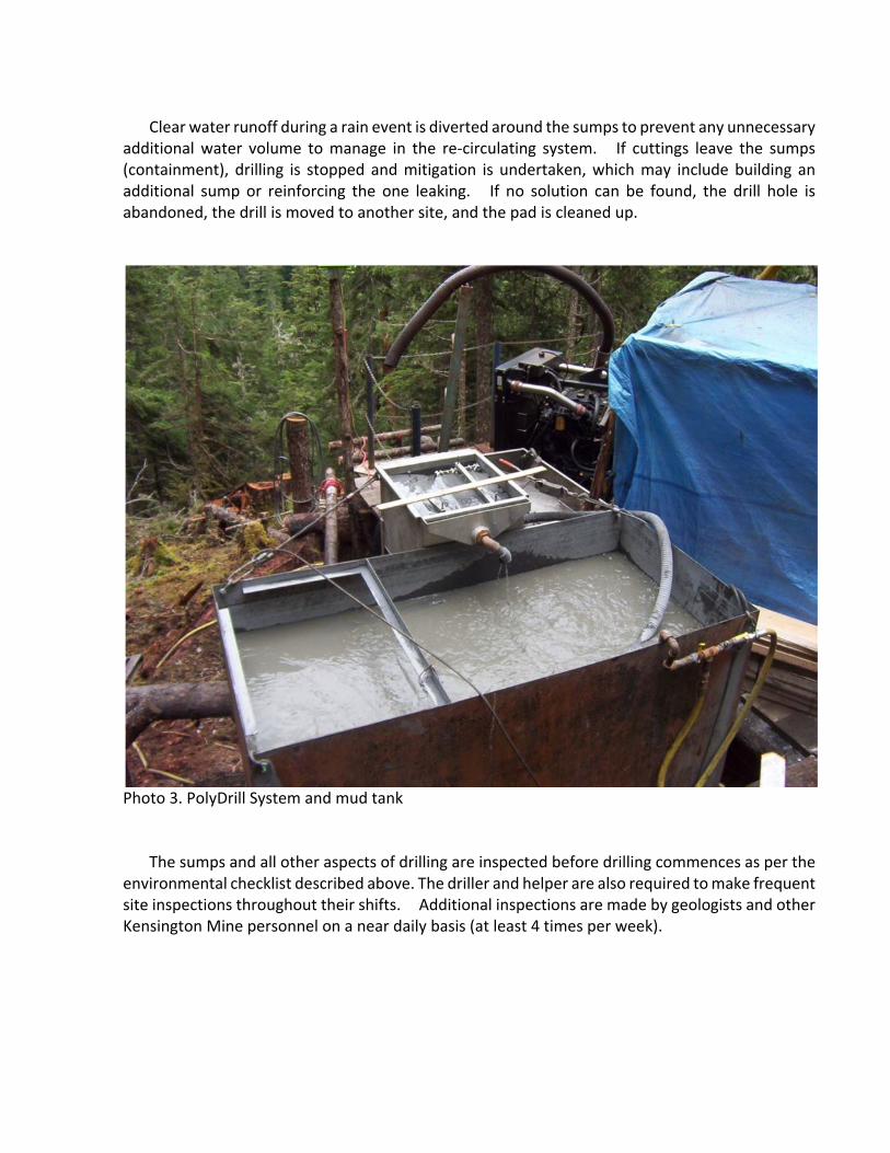
Clear water runoff during a rain event is diverted around the sumps to prevent any unnecessary additional water volume to manage in the re‐circulating system. If cuttings leave the sumps (containment), drilling is stopped and mitigation is undertaken, which may include building an additional sump or reinforcing the one leaking. If no solution can be found, the drill hole is abandoned, the drill is moved to another site, and the pad is cleaned up.
Photo 3. PolyDrill System and mud tank
The sumps and all other aspects of drilling are inspected before drilling commences as per the environmental checklist described above. The driller and helper are also required to make frequent site inspections throughout their shifts. Additional inspections are made by geologists and other Kensington Mine personnel on a near daily basis (at least 4 times per week).

Figure 1. Schematic diagram of water management at a remote drill site.
100+

Appendix 3
Kensington Surface Exploration Guidelines Applicability
These guidelines apply to surface exploration associated with facilities, equipment and personnel
owned/employed by Coeur Alaska. The guidelines cover all activities in surface diamond drilling
which interact with the environment including building drill platforms and drill water sumps, the
drilling process, as well as restoration of drill sites once drilling has ceased. These guidelines also
include instruction for storage of materials used for drilling as well as spill reporting instructions
for Coeur Alaska and contractors involved with surface exploration at Kensington Gold Mine. The
surface exploration supervisors and contract drill foreman are chiefly responsible for insuring
compliance of these guidelines. All Coeur Alaska employees and contractors are responsible for
compliance with these guidelines. The guidelines were instituted to integrate protective measures
into the planning process to prevent and reduce impacts upon the environment, apply technically
proven and practical environmental protection measures throughout the drilling process and to
hold all employees, contractors and supervisors accountable for the implementation of the
guideline.
Definitions
The term “exploration” used in this guideline is defined as activities including surface diamond
drilling, reconnaissance and detailed geological mapping, ground surveying, geochemical sampling
(rocks, soils, and stream silts), and ground geophysical surveying. These road and helicopter‐
supported activities entail no significant surface degradation.
Standard Operating Procedures
A. Construction of Drill Platforms
• Geologists should carefully consider the environment when selecting drill sites.
• Temporary diversion structures may be used if required. • The area disturbed by drilling (the footprint) must be minimized. • In compliance with the USFS requirements, trees will not be felled into or over
stream channels.

B. Pre‐Drilling Contractor Requirements
• All Coeur Alaska environmental requirements should be included in the drilling contract and communicated to the drill operators.
• Drilling equipment must be inspected before work commences to ensure it is fit for work (e.g. hydraulic lines, fuel/oil leaks).
• Drill equipment must be cleaned prior to mobilization onto remote drill site to prevent dispersion of a hazardous substance or oil.
• All drilling personnel are to be trained in the containment and clean‐up of a spilled hazardous substance or oil.
C. Building of Sumps and Containment for Drill Waters
• Every effort will be made to minimize the contact of natural waters with the drilling process.
• Water should be conserved by recirculating fluids where practical. • Sumps will be built down slope of drill sites to trap drill waters and capture any
runoff from the site. • Water from the containments will be visually inspected for a sheen prior to
discharge to the environment. If no sheen is present the accumulated water may be discharged onto the ground adjacent to the pump site.
• The Polydrill system and holding tank are to be used to remove suspended solids (drill cuttings) from the drill water.
• 30 mil PVC liner should be used for the construction of above‐ground sumps.
• Biodegradable materials and products should be used whenever possible especially when intended to be left in the ground.
• Water pumps should be placed in sumps to recirculate water.
• Continuous engineering and modifications to sumps should be used to control drill water when needed.
• Sump design and number of sumps built will be site specific and decided upon by all parties involved. Final approval for all sumps will be given by Coeur Alaska personnel.
• If circulation is lost in a drill hole, a down‐slope ground and creek check must be performed regularly to determine if water is surfacing and inadvertently entering creeks.
• The area of disturbance will be sufficient to control drill waters but every effort must be made to keep the disturbance to a minimum.
• Sumps must allow the escape of people or animals, and must be fenced if depth is greater than 4 feet.
D. Secondary Containment Water Discharge
The condition of rain water retained inside the secondary containment berms is to be examined and documented prior to discharge. Discharge activities are to be

documented on a Petroleum Product Secondary Containment Pumping Log (see below). The procedure for storm water release is as follows:
• Inspect accumulated water and document condition in log. If there is no oil
sheen or floating product containment may be pumped. • If oil sheen or floating product is present. Select the appropriate oil control
method and implement: (a) Faint sheen: absorb oil with absorbent pads prior to discharge (b) Heavy sheen or floating product: absorb oil with absorbent pads or have oil skimmed/vacuumed from water surface prior to discharge.
• Place pump intake on bottom of containment and start pump. Leave 1‐2 inches of water in the containment above the pump intake if there is a visible sheen on top of the water.
• Shutdowns pumps and properly dispose of any oily absorbent material. • Document volume of discharge in log.
E. Water Pump
• Gravity fed water should be used whenever possible to eliminate the need for a water pump.
• The pump will be placed so it is level and stable.
• If possible the pump will be set above any obvious flood level of the stream. • The pump must be within covered containment.
• The pump containment can have a maximum of 2 inches of water present.
• Water discharge from the containment will be accumulated in a contained 55 gallon drum with fresh absorbents placed in the water. If no sheen is present the accumulated water may be discharged onto the ground adjacent to the pump site.
• Transfer fuel barrel and associated supplies must be within containment if being stored at pump.
• Absorbent materials and booms must be present and dry.
• No hazardous substance or oil sheen can be present in the water of a creek. If sheen is found, the Kensington Surface Exploration representative must be notified immediately (see spill reporting Section G below).
• Supplies must be located well above water level.
• Large volume fuel tanks should be used on pumps to minimize need for frequent refueling.
F. Drill Site Environmental Checklist Pre‐shift Forms
• Mandatory pre‐shift cards are to be filled out by both day and night shift drill crews before drilling activities can take place (Appendix A).
• If any boxes are marked —NO on the Environmental Pre‐Shift form,

corrective measures must be taken immediately and documented. • Kensington Surface Exploration representative must be notified immediately,
and a description of the unsatisfactory condition/spill must be documented.
• If warranted, Kensington Environmental Department will be notified by the Kensington Surface Exploration representative or drill foreman.
• Any Surface Exploration representative that finds an environmental issue at the drill site must first notify the drillers and request immediate action to rectify it, and second, the Kensington Exploration representative to report the situation.
G. Reporting Spills
The following spills require reporting to the appropriate agencies within the
specified time frames. Internal reporting guidelines outlined below will be
adhered to in the event of a spill in the quantities of materials listed below:
• Any spill of a hazardous substance or oil that reaches water (water includes a stream, river, lake, and ocean.) must be reported as soon as Coeur Alaska personnel have knowledge of the spill. Any spill of a hazardous substance to land must be reported as soon as Coeur Alaska personnel have knowledge of the spill.
• Any spill of oil to land in excess of 55 gallons must be reported as soon as Coeur Alaska personnel have knowledge of the spill.
• Spills of oil to land greater than 10 gallons but less than 55‐gallons must be reported to the Environmental Department before the end of the shift. The Environmental Department must report the spill to the agency within 48 hours of the release.
• Spills of oil to land that are less than 10 gallons must be reported to the Environmental Department before the end of the shift. The Environmental Department will report the spill to the agency in a monthly report.
• Spills of oil to secondary containment in excess of 55 gallons must be reported to the Environmental Department the same day that the spill occurs. The Environmental Department will report the spill to the agency within 48 hours of the release.
• Spills of grey water in any amount must be reported to the Environmental Department the same day that the spill occurs. The Environmental Department will report the spill to the agency within 24 hours of the release.

Table 1 provides a summary of the spill reporting and initial notification requirements.
Table 1: Spill Reporting and Initial Notification Requirements
Material Media Amount Timeframe Notification
Oil * Land Less than 10 gals. Before end of shift Environmental Manager, or Environmental Personnel
Oil * Land Between 10 and 55 gals. Before end of shift Environmental Manager, or Environmental Personnel
Oil * Land Greater than 55 gals. Immediately Environmental Manager, or Environmental Personnel
Oil * Water (other than mine water)
Any Amount Immediately Environmental Manager, or Environmental Personnel
Hazardous Substance
Any Any Amount Immediately Environmental Manager, or Environmental Personnel
Grey Water (Sewage)
Any Any Amount Before end of shift Environmental Manager, or Environmental Personnel
* Oil as defined previously is any petroleum based product or used material including but not limited to hydraulic oil, gear oil,
motor oil, transmission fluid, diesel fuel, and kerosene
The Environmental Department will be responsible for communicating the spill to the appropriate personnel and agencies. Spill Response and Internal Communications In the event of a spill, the individual who discovers the spill will try to stop the release of material if it is safe to do so and notify her/his supervisor. The supervisor will notify the Environmental Department. As soon as the supervisor has been notified, the individual discovering the release will then proceed to control and contain the spill. The supervisor in consultation with the Environmental Department will mobilize the personnel, materials, and equipment required for a proper spill response and clean‐up. The completed spill report form will be sent to the Environmental Manager. An assessment on how to prevent future similar incidents will be completed. For immediately reportable spills, photos of the spill and clean‐up efforts will be taken and included if possible. The Environmental Manager or his designee will be responsible for notifying proper agencies and Coeur personnel to ensure that internal and regulatory reporting requirements are satisfied. Placards indicating oil spill reporting guidelines are conspicuously posted at storage areas and employee bulletin boards. If the individual discovering the discharge can safely stop or slow it, time doing so is well spent and can be justified as a priority. Internal reporting requirements will be met and appropriate agencies notified as soon as practical, but always within the specified time frames. Sound

judgment must be used to determine priorities during spill response. Consideration should be given to safety, assessing the situation, stopping the source of the spill, controlling the spread of the released material, responder notification, and agency spill reporting requirements. The supervisor in consultation with the Safety and Environmental Departments will assess the magnitude of the spill, evaluate the response requirement, and determine if additional help is needed. The supervisor will also document the actions taken and be responsible for completing the necessary reports of the incident (Spill Report Form, etc.). Spill response and reporting responsibilities are summarized below:
• The person discovering the release will attempt to stop the release if it is safe to do so. • The person who discovers the spill will attempt to stop the spread of the released material. • The person discovering the release will notify their supervisor as soon as the release has
been stopped or discovered and appropriate control measures implemented. • The supervisor is responsible for internal verbal reporting, completing the spill reporting
form and providing the form to the Environmental Department, clean‐up, along with commencing repairs to the equipment causing the release.
• The supervisor will verbally notify the Environmental Department according to the following directions.
• If the material released is oil, to land, in a quantity less than 10 gallons the supervisor will leave a message on the Environmental Manager or someone in the Environmental Department by the end of the shift in which the spill occurs.
• If the material released is oil, to land, in a quantity greater than 10 gallons and less than 55 gallons the supervisor will contact the Environmental Manager or someone in the Environmental Department by the end of the shift. Do not rely on voice mail – the supervisor must be certain the spill has been communicated.
• Immediately Reportable ‐ For spills of oil that reach water (ocean, stream, or river.) or are greater than 55 gallons and spills of hazardous materials in any quantity the supervisor must contact the Environmental Manager, or someone in the Environmental Department (at home if needed) as soon as possible but no later than one hour following the spill. Do not rely on voice mail – the supervisor must be certain the spill has been communicated. For spills in the mine that reach mine water the spill must be reported immediately so that the water treatment plant can be notified and measures implemented to prevent an unacceptable impact to plant operation.
• The supervisor will forward the spill reporting form to the Environmental Department as soon as possible but no later than the end of the shift following the release.
• The Environmental Manager or his designee will notify the appropriate Coeur personnel and following completion of the internal notifications, report spills to the appropriate agencies.

Completing the Spill Report Form
The supervisor completing the spill reporting form must assure the information on the form is accurate to the best of her/his knowledge. The form should be completed with the understanding that the spill report form is a public document that may be reviewed by auditors, agencies and the public. Care should be taken to avoid the use of offensive language, slang, and confusing verbiage. State the facts and do not make assumptions or predictions.
Line 1: Note the date and time the spill occurred along with the name of the person completing the spill report form.
Line 2: Note the name of the employee causing the spill or operating the
equipment when the spill occurred. If the individual is the employee of a contractor, include the contractor’s name.
Line 3: Note the equipment number or tank number involved in the spill.
If more than one piece of equipment, i.e. a lube truck and a mucker, are involved in a spill, include both pieces of equipment.
Line 4: Note the location of the spill. Be as accurate as possible including
the bearing and distance from a building or intersection. Example: 150‐feet north of the mill.
Line 5: Briefly describe the incident causing the spill. Care should be
taken to include any and all conditions that contributed to the spill. Condition of hoses, lines, pipes or other equipment/parts involved in the spill should be noted. Be brief and thorough in the description.
Line 6: Include the quantity and material spilled. Be accurate in your
assessment of the volume. Methods such as noting the amount of oil required to fill the tank following repair of the equipment or a volume based on area and depth are examples of acceptable methods of estimating the volume.
Line 7: An estimate of the volume contained and any material recovered
should be noted. Material should only be considered to be contained if it is captured in another container such as a pail, drum, loader bucket, etc. If material lands on the ground, even if it is contained by a berm or absorbent material, it should be included in the quantity spilled and should not be considered contained for this purpose. Material recovered from the ground or another container should be included in the quantity recovered. Pictures along with notes, drawings and calculations used to determine the
volumes should be included as attachments to the Spill Report Form.
Line 8: An estimate of the area impacted by the spill and the quantity of
soil removed during cleanup should be included. Measurements should be taken of the area impacted. The volume of material should be estimated based on load counts or measurements of the area excavated. Notes, drawings and calculations used to determine the area and volume should be included as attachments to the Spill Report Form.
Line 9: Spill reporting requirements and cleanup efforts vary depending
upon the media impacted by the spill. For spills on land please note the surface type, i.e. compacted road surface, drift rib, compacted development rock, ice, etc. If a spill is released to water (mine water is not considered water for spill reporting purposes), please note the ocean, stream, pond, or lake that the material spilled impacts.
Line 10: The source of spilled material is typically a hydraulic hose, fuel
line, pipeline, tank, pump etc. Please be as specific as possible when describing the source.
Line 11: A brief description of the method used to clean‐up the spill should
be included in this section. Please include materials used (absorbent materials, material used to construct berms, etc.) or equipment used to excavate the contaminated soil/rock. Be brief but thorough in your description.
Line 12: Materials used or excavated during the clean‐up will require
proper disposal. Please consult the Environmental Department before disposing of materials used/generated during spill cleanup. The description of the disposal method must include the date and location the materials used/generated during spill cleanup is ultimately disposed of.
Line 13: Personnel, including the Department Manager, should discuss the
spill and determine the most effective means of preventing another occurrence of the spill. The measures implemented to prevent another spill from occurring should be documented in this section.
Line 14: If the spill occurs on the surface, the weather conditions at the
time of the spill should be noted. Temperature, an estimate of

wind speed and direction, along with precipitation/snow conditions should be noted.
Line 15: If the spill enters the ocean or the shore the status of the tide
should be noted. Line 16: The person contacted, date and time that the Environmental
Department is verbally notified of the spill should be noted. Line 17: The person completing the spill report should sign and date the
form. Lines 18 & 19 will be completed by the Environmental Department at the time the spill is reported to the agencies. The completed spill report from must be provided to the Environmental Department by the end of the shift when the spill occurs. Please provide a copy to the Environmental Manager.
H. Interaction with Wildlife
• All trash must be removed from drill site at the end of each day.
• Drilling products and materials that may attract bears will be kept to a minimum at the drill site, and always on the drill pad in secondary containment.
I. Clean‐Up and Restoration of Drill Sites
• Drill sites must be kept clean and orderly throughout the drilling process. • No open ground fires are permitted on the drill site.
• Toilet holes must be located away from water bodies and buried with at least 6 inches of soil.
• Upon finishing at a drill site all foreign materials must be removed, including non‐native wood products.
• An effort must be made to recover all casing.
• Restoration of sumps must include removal of the sump liner.
• All sites will be photographed and date‐stamped to document that clean ‐up and restoration are complete.


