de.ariat-tech.com · Tab le of Contents 1 Introduction 1 Thermal Properties & Testing 4 Interface...
93
Thermally Conductive Interface Materials for Cooling Electronic Assemblies Sil-Pad ® SELECTION GUIDE
Transcript of de.ariat-tech.com · Tab le of Contents 1 Introduction 1 Thermal Properties & Testing 4 Interface...

Thermally Conductive
Interface Materials for
Cooling Electronic Assemblies
Sil-Pad®
S E L E C T I O N G U I D E

Table of Contents
1
Introduction 1Thermal Properties & Testing 4Interface Material Selection Guide 5
Gap Pad® Thermally Conductive Materials 6Gap Pad Comparison Data 7Frequently Asked Questions 8Gap Pad VO® 9Gap Pad VO Soft® 10Gap Pad VO Ultra Soft 11Gap Pad 1000SF 12Gap Pad HC1000 13Gap Pad 1500 14Gap Pad 1500R 15Gap Pad A2000 16Gap Pad 2000S40 17Gap Pad 2500S20 18Gap Pad 2500 19Gap Pad A3000 20Gap Pad 3000S30 21Gap Filler 1000 22Gap Filler 1100SF 23Gap Filler 2000 24
TIC™ - Thermal Interface Compound 25Comparison Data & FAQ’s 25TIC 1000G 26TIC 1000A 27TIC 2000A 28TIC 4000 29
Hi-Flow ® Phase Change Interface Materials 30Hi-Flow Comparison Data 31Frequently Asked Questions 32Hi-Flow 105 33Hi-Flow 115-AC 34Hi-Flow 225F-AC 35Hi-Flow 225FT 36Hi-Flow 225UF 37Hi-Flow 225UT 38Hi-Flow 225U 39Hi-Flow 625 40Hi-Flow 300P 41Hi-Flow 300G 42
Sil-Pad® Thermally Conductive Insulators 43Sil-Pad Comparison Data 44Frequently Asked Questions 45Choosing Sil-Pad Thermally Conductive Insulators 46Mechanical, Electrical and Thermal Properties 48Sil-Pad Applications 50Selection Guide 50Sil-Pad 400 52Sil-Pad 800 53Sil-Pad 900S 54Sil-Pad 980 55Sil-Pad A1500 56Sil-Pad 1500ST 57Sil-Pad 1750 58Sil-Pad 2000 59Sil-Pad A2000 60Sil-Pad K-4 61Sil-Pad K-6 62Sil-Pad K-10 63Q-Pad® II 64Q-Pad 3 65Poly-Pad® 1000 66Poly-Pad K-4 67Poly-Pad K-10 68Sil-Pad Tubes 69Sil-Pad Shield 70
Bond-Ply® & Liqui-Bond™ Adhesives 71Bond-Ply & Liqui-Bond Comparison Data 72Frequently Asked Questions 72Bond-Ply 100 73Bond-Ply 400 74Bond-Ply 660B 75Liqui-Bond SA 2000 76
Solutions for Surface Mount Applications 78Ordering Information 80
Sil-Pad Configurations - Imperial 82Hi-Flow Configurations - Imperial 85Sil-Pad Configurations - Metric 86Hi-Flow Configurations - Metric 89Sil-Pad Shield 90

2
INTR
OD
UC
TIO
N
At Bergquist, developing high quality
components for the electronics
industry is our first priority. As a
world-leading manufacturer with
state-of-the-art facilities, we serve a
multitude of industries worldwide
including automotive, computer,
consumer electronics, military, motor
control, power conversion,
telecommunications and more.
We make it our business to know
your business. We understand your
problems. We also know that there
will always be a better way to help
you reach your goals and objectives.
To that end, our company continually
invests considerable time and money
into research and development. The
Bergquist Company is focused on a
single purpose – discovering the
need, then developing and delivering
technologically advanced solutions
backed by superior service.
World Leader inThermal Management ThroughTechnology, Innovation & Service
Bergquist Takesthe Heat
Thermal Management Products
Bergquist's Thermal Products Group is a worldleading developer and manufacturer of thermalmanagement materials which provide productsolutions to control and manage heat inelectronic assemblies and printed circuitboards. Used by many of the world’s largestOEMs in various industries including auto-motive, computer, power supply, military andmotor control, these materials include:
Sil-Pad® – Thermally Conductive Insulators
Bond-Ply® & Liqui-Bond™ – ThermallyConductive Adhesives
Gap Pad® – Thermally ConductiveGap Filling Materials
Hi-Flow® – Phase Change Interface Materials
TIC™ – Thermal Interface Compound
Thermal Clad® – Insulated Metal Substrates
World Class OperationsAround the Globe
Worldwide Locations
In the United States, the Thermal ProductsGroup’s 90,000 square foot manufacturingfacility is located in Cannon Falls, Minnesota.A 40,000 square foot facility in Prescott,Wisconsin houses the Thermal Clad printedcircuit board operations. A 130,000 squarefoot facility in Chanhassen, Minnesota is thelocation for Bergquist’s corporate headquartersand state of the art research and developmentfacilities.Worldwide, Bergquist has facilities inThe Netherlands, Germany, the UnitedKingdom,Taiwan, Korea, Hong Kong andChina with sales representatives in 30countries to support worldwide growth.

3
INTRO
DU
CTIO
NG
AP PA
DTIC
HI--FLO
WSIL-PA
DBO
ND
-PLYO
RDERIN
G
A Legacy of Industry-Leading Technology
New Product Innovation
For over 35 years, outstanding quality,innovation and engineering have been hall-marks of The Bergquist Company. Today,developing innovative products for theelectronics industry remains our first priority.Bergquist has developed over 260 materialswhich provide thermal solutions for a widevariety of electronic applications. Many of ourproducts were originally developed to satisfya customer request for a specific materialdesigned to perform to their particularspecifications.This “can do” attitude andcustomized technology has earned TheBergquist Company its QS 9000 certificationahead of competitors, and will position thecompany as an industry leader by earlycertification to ISO 9001: 2000.
Research & Developmentat the Speed of Change
R&D Facilities
Keeping pace in today’s aggressive electronicsindustry demands continual anticipation ofchange and the ability to develop customer-driven solutions quickly and efficiently. OurChanhassen headquarters features astate-of-the-art development laboratory andengineering department staffed with highlyskilled chemical engineers, laboratorytechnicians and manufacturing engineers – alldedicated to researching, developing andtesting new materials. From such dedicationhas come many industry-standard proprietaryproducts including Thermal Clad, Sil-Pad, GapPad, Bond-Ply and Hi-Flow materials.

Thermal Properties & Testing
4
INTR
OD
UC
TIO
N
Thermal ConductivityThe time rate of heat flow through a unit area producing a unittemperature difference across a unit thickness.
Thermal conductivity is an inherent or absolute property of the material.
Thermal ImpedanceA property of a particular assembly measured by the ratio of thetemperature difference between two surfaces to the steady state heatflow through them.
Factors affecting thermal impedance include:
Area: Increasing the area of thermal contact decreasesthermal impedance.Thickness: Increasing the insulator thickness increasesthermal impedance.Pressure: Increasing mounting pressure under ideal conditionsdecreases thermal impedance.Time: Thermal impedance decreases over time.Measurement: Thermal impedance is affected by the method oftemperature measurement.
Thermal Impedance Per Bergquist TO-220 ThermalPerformance (25˚C Cold Plate Testing)
Thermal ResistanceThe opposition to the flow of heat through a unit area of materialacross an undefined thickness.
Thermal resistance varies with thickness.
Test Methods – ASTM D5470
2 in. diameter stack (ref. 3.14 in2) – 10-500* psi, 1 hour per layer* Bergquist modified
i

Interface Material Selection Guide
5
INTRO
DU
CTIO
N
Market Applications Products Dis
cret
e Po
wer
Dev
ices
for
Pow
er S
uppl
ies,
Com
pute
rs,
Tel
ecom
(Thr
u-H
ole)
Act
ive
Pow
er C
ompe
nsat
ors:
Cap
acito
rs, I
nduc
tors
, Res
isto
rs
Elec
tron
ic M
odul
es f
orA
utom
otiv
e:
Mot
or &
wip
erC
ontr
ols,
Ant
i-Loc
k, e
t.
Elec
tron
ic M
odul
es f
or T
elec
oman
d Po
wer
Sup
plie
s
Com
pute
r A
pplic
atio
ns: C
PU,
GPU
, ASI
Cs,
Har
d D
rive
s
Elec
tric
al In
sula
tor
Clip
, Low
Pres
sure
Scre
w/R
ivet
s, H
igh
Pres
sure
Not
App
licab
le
Shee
t St
ock
Rol
l-For
m C
ontin
uous
Stan
dard
Con
figur
atio
ns
Cus
tom
Exte
rnal
Sha
pes
Cus
tom
Inte
rnal
Fea
ture
s
Stan
dard
PSA
Offe
ring
s
Q-Pad II T T T T T T A A A A A AQ-Pad 3 T T T T T T A A A A A AHi-Flow 105 T AS AS T A A A A A AHi-Flow 115-AC T T T T A A A A A AHi-Flow 300G T T T T AS A A A A A AHi-Flow 225F-AC T T T A A A AS NAHi-Flow 225FT T T T A A A AS NAHi-Flow 225UT T T A A A AS NAHi-Flow 225U T T A A A ASHi-Flow 225UF T T A A A ASHi-Flow 625 T T T A A A A A AHi-Flow 300P T T T A A A A A A
Bonding - Thin-Film Bond-Ply 660B T T T T T A A A A A ABonding - Fiberglass Bond-Ply 100 T T T T T A A A A A ABonding -Unreinforced
Bond-Ply 400 T T T T T A A A A A A
Sil-Pad - Fiberglass Sil-Pad 400 T T T T T T A A A A A ASil-Pad 800 T T T T T A A A A A ASil-Pad 900S T T T T T T A A A A A ASil-Pad 980 T T T T A A A A A ASil-Pad A1500 T T T T T T A A A A A ASil-Pad 1500ST T T T T T T A A A A A ASil-Pad 1750 T T T T T T A A A A A ASil-Pad 2000 T T T T AS T A A A A A ASil-Pad A2000 T T T T AS T A A A A A ASil-Pad K-4 T T T T T T A A A A A ASil-Pad K-6 T T T T T T A A A A A ASil-Pad K-10 T T T T T T A A A A A A
Gap Pad Gap Pad VO T T T T T T T A A* A A AS AGap Pad VO Soft T T T T T T T A A* A A AS AGap Pad VO Ultra Soft T T T T T T T A A* A A AS AGap Pad 1000SF T T T T T T T A A* A A AS AGap Pad HC1000 T T T T T A A* A A AGap Pad1500 T T T T T A A* A A ASGap Pad 1500R T T T T T T A A* A A AGap Pad A2000 T T T AS T T A A* A A AGap Pad 2000S40 T T T AS T T A A* A A AGap Pad 2500S20 T T T AS T T A A* A A AGap Pad 2500 T T T AS T T A A* A A AGap Pad A3000 T T T T AS T T A A* A A AGap Pad 3000S30 T T T T AS T T A A* A A A
Gap Filler Gap Filler 1000 T T T T AS T AGap Filler 1100SF T T T T T AS T AGap Filler 2000 T T T T AS T A
Liquid Adhesive Liqui-Bond SA 2000 T T AS T A
T = Typical, AS = Application-Specific (contact Bergquist Sales); A = Available, * = up to 40 mil only.Note: For Hi-Flow 225UT, Hi-Flow 225FT, and Hi-Flow 225F-AC, the adhesive is not a PSA.
Sil-Pad - Thin FilmPolyimide
Grease ReplacementMaterials - Insulated
Grease ReplacementMaterials
TYPICAL CONVERTEDOPTIONS
MOUNTINGMETHODSPRODUCT OVERVIEW INTERFACE APPLICATIONS

Gap Pad® Thermally Conductive Materials
6
GA
P PA
D
Solution-Driven Thermal Management Products for Electronic Devices
The Bergquist Company, a world leader in thermal interface materials,developed the Gap Pad family to meet the electronics industry’s growing need for interface materials with greater conformability,higher thermal performance and easier application.
The extensive Gap Pad family provides an effective thermal interfacebetween heat sinks and electronic devices where uneven surfacetopography, air gaps and rough surface textures are present. Bergquistapplication specialists work closely with customers to specify the properGap Pad material for each unique thermal management requirement.
A Complete Range of Choices for Filling Air Gaps and Enhancing Thermal Conductivity
FeaturesEach of the many products withinthe Gap Pad family is unique inits construction, properties andperformance. Following is anoverview of the importantfeatures offered by theGap Pad family.
• Low-modulus polymer material
• Available with fiberglass/rubbercarriers or in a non-reinforcedversion
• Special fillers to achieve specificthermal and conformabilitycharacteristics
• Highly conformable to unevenand rough surfaces
• Electrically isolating
• Naturally tacky one-side ortacky on both sides withprotective liner
• Variety of thicknesses andhardnesses
• Range of thermal conductivities
• Available in sheets anddie-cut parts
BenefitsGap Pad thermal products aredesigned to improve an assembly’sthermal performance and reliabilitywhile saving time and money.Specifically:
• Eliminates air gaps to reduce thermal resistance
• High conformability reduces interfacial resistance
• Low-stress vibration dampening
• Shock absorbing
• Easy material handling
• Simplified application
• Puncture, shear and tearresistance
• Improved performance for high-heat assemblies
• Compatible with automated dispensing equipment
OptionsSome Gap Pad products havespecial features for particularapplications, including:
• Available with or withoutadhesive
• Rubber-coated fiberglass reinforcement
• Thicknesses from 0.010''to 0.250''
• Available in custom die-cutparts, sheets and rolls(converted or unconverted)
• Custom thicknesses and constructions
• Adhesive or naturalinherent tack
We produce thousands of specials.Tooling charges vary dependingon tolerance and complexity ofthe part.
ApplicationsGap Pad products are well suitedto a wide variety of electronics,automotive, medical, aerospaceand military applications such as:
• Between an IC and a heat sinkor chassis.Typical packagesinclude BGA’s, QFP, SMT powercomponents and magnetics
• Between a semiconductor andheat sink
• CD-ROM/DVD cooling
• Heat pipe assemblies
• RDRAM memory modules
• DDR SDRAM
• Hard drive cooling
• Power supply
• Signal amplifiers
• Between other heat generatingdevices and chassis
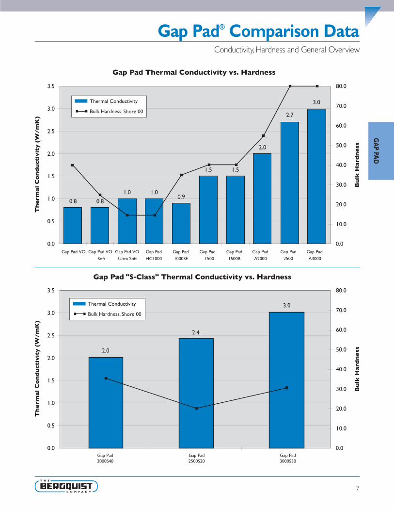
Gap Pad® Comparison Data
7
GA
P PAD
Conductivity, Hardness and General Overview

8
GA
P PA
D
Frequently Asked Questions
Q: What thermal conductivity test method was used toachieve the values given on the data sheets?
A: The Anter Quickline 10 was used to run this test. Bergquist haspublished an application note about the modifications to theASTM D5470 test method to appropriately test Gap Pad materialsat low 10 pressure (see Bergquist Application Note #112).
Q: Is Gap Pad offered with an adhesive?A: Currently the standard Gap Pads, which include Gap Pad VO,
Gap Pad VO Soft, and Gap Pad VO Ultra Soft are offered with orwithout an adhesive on the Sil-Pad 800/900 carrier side of thematerial.The remaining surface has natural inherent tack. All otherGap Pads have inherent tack.
Q: Is the adhesive repositionable?A: Depending on the surface being applied to, if care is taken, the
pad may be repositioned. Special care should be taken whenremoving the pad from aluminum or anodized surfaces to avoidtearing or delamination.
Q: What is meant by “naturally tacky”?A: The characteristic of the rubber itself has a natural inherent tack,
without the addition of an adhesive.As with adhesive backedproducts, the naturally tacky surfaces may help in the assemblyprocess to temporarily hold the pad in place while the applicationis being assembled. Unlike adhesive backed products, inherent tackdoes not have a thermal penalty since the rubber itself has thetack.Tack strength varies from one Gap Pad product to the next.
Q: Is the naturally tacky side of the Gap Pad reposition-able?
A: Again, depending on the material that the pad is applied to, inmost cases they are repositionable. Again, care should be takenwhen removing the pad from aluminum or anodized surfaces asto avoid tearing or delaminating the pad.The naturally tacky sideis always easier to reposition than an adhesive side.
Q: Is Gap Pad reworkable?A: Depending on the application and the pad being used, Gap Pad
has been reworked in the past. Bergquist has customers that arecurrently using the same pad for reassembling their applicationsafter burn-in processes and after fieldwork repairs. However, thisis left up to the design engineer’s judgment as to whether or notthe Gap Pad will withstand reuse.
Q: Is liquid Gap Filler reworkable?A: It is highly dependent on the strength of the application and its
surface topography. Liquid Gap Filler will cure with low adhesivestrength to the application surfaces.
Q: Will heat make the material softer?A: In the temperature range of -60°C to 200°C, there is no
significant variance in hardness, for silicone Gap Pads andGap Fillers.
Q: What is the life expectancy of Gap Pad?A: The silicone rubber industry recognizes a 20-year life for
silicone rubber when used within specified operation parameters.Bergquist has made pad material that has been in applications forsome 30 years without any known signs of deterioration.
Q: What is the shelf life of Gap Pad?A: Shelf life for Gap Pad is one (1) year after date of manufacture.
For Gap Pad with adhesive, the shelf life is six (6) months afterthe date of manufacture. After these dates, inherent tack andadhesive properties should be recharacterized.
Q: What are the upper processing temperature limits forGap Pad and for how long?
A: Gap Pads that are pink, mauve or gold in color are more stable atelevated temperatures. Gap Pad in general can be exposed totemporary processing temperatures of 250°C for five minutesand 300°C for one minute.
Q: Is Gap Pad electrically isolating?A: Yes, all Gap Pad materials are electrically isolating. However, keep
in mind that Gap Pad is designed to FILL gaps, not forguaranteeing them in high stress applications.
Q: How much force will the pad place on my device?A: Refer to the Pressure vs. Deflection charts in Bergquist
Application Note #116.
Q: Will Gap Pad and Gap Filler work in my application?What size gaps will Gap Pad and Gap Filleraccommodate?
A: Gap Pad and Gap Filler can be used wherever air can bereplaced, such as between a heat generating device and a heatsink, heat spreader or housing.This can be done using one sheetof Gap Pad or individual pieces of appropriate thicknesses, or byusing Gap Filler if stack-up tolerances and height variationsare significant.
Q: What is meant by “compliance” and “conformability,”and why is this important?
A: The better a Gap Pad complies and conforms to a rough orstepped surface, the less interfacial resistance will be present dueto air voids and air gaps.This leads to a lower overall thermalresistance of the pad between the two interfaces.
Q: Is anything given off by the material (i.e. extractables,outgassing)?
A: 1) Gap Pad and Gap Filler, like all silicone pads, can extract siliconefluid (refer to Bergquist Application Note #56). Also note thatGap Pad and Gap Filler have the lowest extraction value forsilicone-based gap filling products on the market.
2) Primarily for aerospace applications, outgassing data is detailedin Bergquist Application Note #117, tested per ASTM E595.
Q: How is extraction testing performed?A: The test method used is the Bellcore Extraction method
#TR-NWT-000930; refer to Bergquist Application Note #56.

9
GA
P PAD
Gap Pad VO®
Features and Benefits• Thermal conductivity = 0.8W/mK
• Enhanced puncture, shear, & tear resistance
• Conformable gap filling material
• Electrically isolating
Gap Pad VO is a cost effective thermallyconductive interface.The material is a filledthermally conductive polymer supplied on arubber-coated fiberglass carrier allowing foreasy material handling.The conformablenature of Gap Pad VO allows the pad to fill inair gaps between PC boards and heat sinksor a metal chassis.Note: Resultant thickness is defined as the final gapthickness of the application.
Conformable,Thermally Conductive Material for Filling Air Gaps
Typical Applications Include:• Telecommunications
• Computer and peripherals
• Power conversion
• Between heat generating semiconductors and a heat sink
• Area where heat needs to be transferred to a frame, chassis, or other type of heat spreader
• Between heat generating magnetic components and a heat sink
Configurations Available:• Sheet form and die-cut parts
Building a Part Number Standard Options
Note: To build a part number, visit our website at www.bergquistcompany.com.
Gap Pad®: U.S. Patent 5,679,457 and others.
Thickness vs. Thermal ResistanceGap Pad VO
0
50
100
150
200
250
1 3 5 7 9 11 13
Thermal Resistance (°C-in2/W)
Res
ulta
nt T
hick
ness
(m
ils)
GPVO - 0.040 - AC - 0816 - NA �example
NA = Selected standard option. If not selecting astandard option, insert company name, drawingnumber, and revision level.
0816 = Standard Sheet Size 8" X 16",00 = Custom Configuration
AC = Adhesive one side,00 = No pressure sensitive adhesive
Standard Thicknesses Available: 0.020", 0.040",0.060", 0.080", 0.100", 0.125", 0.160", 0.200", 0.250"
GPVO = Gap Pad VO Material
Sect
ion
A
Sect
ion
B
Sect
ion
C
Sect
ion
E
Sect
ion
D
TYPICAL PROPERTIES OF GAP PAD VOPROPERTY IMPERIAL VALUE METRIC VALUE TEST METHODColor Gold/Pink Gold/Pink Visual
Reinforcement Carrier Sil-Pad Sil-Pad —
Thickness (inch) / (mm) 0.020 to 0.250 0.508 to 6.350 ASTM D374
Inherent Surface Tack (1 or 2 sided) 1 1 —
Density (g/cc) 1.6 1.6 ASTM D792
Heat Capacity (J/g-K) 1.0 1.0 ASTM C351
Hardness, Bulk Rubber (Shore00) (1) 40 40 ASTM D2240
Young’s Modulus (psi) / (kPa) (2) 100 689 ASTM D575
Continuous Use Temp (°F) / (°C) -76 to 392 -60 to 200 —
ELECTRICALDielectric Breakdown Voltage (Vac) >6000 >6000 ASTM D149
Dielectric Constant (1000 Hz) 5.5 5.5 ASTM D150
Volume Resistivity (Ohm-meter) 1011 1011 ASTM D257
Flame Rating 94 V-O 94 V-O U.L.
THERMALThermal Conductivity (W/m-K) 0.8 0.8 ASTM D5470
1) One second delay value Shore 00 hardness scale.2) Young's Modulus, calculated using 0.01 in/min. step rate of strain with a sample size of 0.79 inch2. For more information on Gap Pad
modulus, refer to Bergquist Application Note #116.

10
GA
P PA
D
Features and Benefits• Thermal conductivity = 0.8W/mK
• Conformable low hardness
• Enhanced puncture, shear, & tear resistance
• Electrically isolating
Gap Pad VO Soft is recommended forapplications that require a minimum amountof stress on components. Gap Pad VO Softis a highly conformable, low modulus filledsilicone polymer on a rubber coated fiberglasscarrier.The material can be used as aninterface where one side is in contact witha leaded device.Note: Resultant thickness is defined as the final gapthickness of the application.
Gap Pad VO Soft®
Highly Conformable,Thermally Conductive Material for Filling Air Gaps
Thickness vs. Thermal Resistance Gap Pad VO Soft
20406080
100120140160180200
1 2 3 4 5 6 7 8 9 10
Thermal Resistance (°C-in2/W)
Res
ulta
ntT
h ic k
n es s
( mi l s
)
Typical Applications Include:• Telecommunications
• Computer and peripherals
• Power conversion
• Between heat-generating semiconductors or magnetic components and a heat sink
• Area where heat needs to be transferred to a frame, chassis, or other type of heat spreader
Configurations Available:• Sheet form and die-cut parts
Building a Part Number Standard Options
Note: To build a part number, visit our website at www.bergquistcompany.com.
Gap Pad®: U.S. Patent 5,679,457 and others.
GPVOS - 0.060 - AC - 00 - ACME10256 Rev. a �example
NA = Selected standard option. If not selecting astandard option, insert company name, drawingnumber, and revision level.
0816 = Standard Sheet Size 8" X 16",00 = Custom Configuration
AC = Pressure sensitive adhesive one side,00 = No pressure sensitive adhesive
Standard Thicknesses Available: 0.020", 0.040",0.060", 0.080", 0.100", 0.125", 0.160", 0.200"
GPVOS = Gap Pad VO Soft Material
S ec t
ion
A
S ec t
ion
B
S ec t
ion
C
S ec t
ion
E
S ec t
ion
D
TYPICAL PROPERTIES OF GAP PAD VO SOFTPROPERTY IMPERIAL VALUE METRIC VALUE TEST METHODColor Mauve/Pink Mauve/Pink Visual
Reinforcement Carrier Sil-Pad Sil-Pad —
Thickness (inch) / (mm) 0.020 to 0.200 0.508 to 5.000 ASTM D374
Inherent Surface Tack (1 or 2 sided) 1 1 —
Density (g/cc) 1.6 1.6 ASTM D792
Heat Capacity (J/g-K) 1.0 1.0 ASTM C351
Hardness, Bulk Rubber (Shore00) (1) 25 25 ASTM D2240
Young’s Modulus (psi) / (kPa) (2) 40 275 ASTM D575
Continuous Use Temp (°F) / (°C) -76 to 392 -60 to 200 —
ELECTRICALDielectric Breakdown Voltage (Vac) >6000 >6000 ASTM D149
Dielectric Constant (1000 Hz) 5.5 5.5 ASTM D150
Volume Resistivity (Ohm-meter) 1011 1011 ASTM D257
Flame Rating 94 V-O 94 V-O U.L.
THERMALThermal Conductivity (W/m-K) 0.8 0.8 ASTM D5470
1) One second delay value Shore 00 hardness scale.2) Young's Modulus, calculated using 0.01 in/min. step rate of strain with a sample size of 0.79 inch2. For more information on Gap Pad
modulus, refer to Bergquist Application Note #116.

11
GA
P PAD
Gap Pad® VO Ultra SoftUltra Conformable,Thermally Conductive Material for Filling Air Gaps
Features and Benefits• Thermal conductivity = 1.0 W/mK
• Highly conformable low hardness
• Gel-like modulus
• Designed for low stress applications
• Puncture, shear, & tear resistant
Gap Pad VO Ultra Soft is recommended forapplications that require a minimum amountof stress on components.The viscoelastic natureof the material also gives excellent low stressvibration dampening and shock absorbingcharacteristics. Gap Pad VO Ultra Soft is anelectrically isolating material, which allows its usein applications requiring isolation between heatsinks and high voltage, bare leaded devices.Note: Resultant thickness is defined as the final gapthickness of the application.
Typical Applications Include:• Telecommunications
• Computer and peripherals
• Power conversion
• Between heat generating semiconductors or magnetic components and a heat sink
• Area where heat needs to be transferred to a frame, chassis, or other type of heat spreader
Configurations Available:• Sheet form and die-cut parts
Building a Part Number Standard Options
Note: To build a part number, visit our website at www.bergquistcompany.com.
Gap Pad®: U.S. Patent 5,679,457 and others.
Thickness vs. Thermal ResistanceGap Pad VO Ultra Soft
0
50
100
150
200
250
1 3 5 7 9 11 13
Thermal Resistance (°C-in2/W)
Res
ulta
ntT
h ic k
n es s
( mi l s
)
GPVOUS - 0.100 - AC - 0816 - NA �example
NA = Selected standard option. If not selecting astandard option, insert company name, drawingnumber, and revision level.
0816 = Standard Sheet Size 8" X 16",00 = Custom Configuration
AC = Pressure sensitive adhesive one side,00 = No pressure sensitive adhesive
Standard Thicknesses Available: 0.020", 0.040",0.060", 0.080", 0.100", 0.125", 0.160", 0.200", 0.250"
GPVOUS = Gap Pad VO Ultra Soft Material
Sect
ion
A
S ec t
ion
B
S ec t
ion
C
Sec t
ion
E
Sec t
ion
D
TYPICAL PROPERTIES OF GAP PAD VO ULTRA SOFTPROPERTY IMPERIAL VALUE METRIC VALUE TEST METHODColor Mauve/Pink Mauve/Pink Visual
Reinforcement Carrier Sil-Pad Sil-Pad —
Thickness (inch) / (mm) 0.020 to 0.250 0.508 to 6.350 ASTM D374
Inherent Surface Tack (1 or 2 sided) 1 1 —
Density (g/cc) 1.6 1.6 ASTM D792
Heat Capacity (J/g-K) 1.0 1.0 ASTM C351
Hardness, Bulk Rubber (Shore 00) (1) 5 5 ASTM D2240
Young’s Modulus (psi) / (kPa) (2) 8 55 ASTM D575
Continuous Use Temp (°F) / (°C) -76 to 392 -60 to 200 —
ELECTRICALDielectric Breakdown Voltage (Vac) >6000 >6000 ASTM D149
Dielectric Constant (1000 Hz) 5.5 5.5 ASTM D150
Volume Resistivity (Ohm-meter) 1011 1011 ASTM D257
Flame Rating 94 V-O 94 V-O U.L.
THERMALThermal Conductivity (W/m-K) 1.0 1.0 ASTM D5470
1) One second delay value Shore 00 hardness scale.2) Young's Modulus, calculated using 0.01 in/min. step rate of strain with a sample size of 0.79 inch2. For more information on Gap Pad
modulus, refer to Bergquist Application Note #116.

12
GA
P PA
D
Gap Pad® 1000SFThermally Conductive Silicone-Free Gap Filling Material
Features and Benefits• Thermal conductivity = 0.9 W/mK
• No silicone outgassing
• No silicone extraction
• Reduced tack on one side to aid inapplication assembly
The new Gap Pad 1000SF is a thermallyconductive, electrically insulating, silicone-freepolymer specially designed for silicone-sensitive applications.The material is idealfor applications with high standoff andflatness tolerances. Gap Pad 1000SF is rein-forced for easy material handling and addeddurability during assembly.The material isavailable with a protective liner on bothsides of the material.Note: Resultant thickness is defined as the final gapthickness of the application.
Thickness vs. Thermal ResistanceGap Pad 1000SF
0
25
50
75
100
125
0 1 2 3 4 5
Thermal Resistance (°C-in2/W)
Res
ulta
ntT
h ic k
n es s
( mi l s
)
Typical Applications Include:• Digital disk drives / CD-ROM
• Automotive modules
• Fiber optics modules
Configurations Available:• Sheet form
• Die-cut parts
Building a Part Number Standard Options
Note: To build a part number, visit our website at www.bergquistcompany.com.
Gap Pad®: U.S. Patent 5,679,457 and others.
GP1000SF - 0.010 - 01 - 0816 - NA �example
NA = Selected standard option. If not selecting astandard option, insert company name, drawingnumber, and revision level.
0816 = Standard Sheet Size 8" X 16",00 = Custom Configuration
01 = Naturally tacky one side
Standard Thicknesses Available: 0.010", 0.015",0.020", 0.040", 0.060", 0.080", 0.100", 0.125"
GP1000SF = Gap Pad 1000SF Material
Sect
ion
A
Sect
ion
B
S ec t
ion
C
Sect
ion
E
Sec t
ion
D
TYPICAL PROPERTIES OF GAP PAD 1000SFPROPERTY IMPERIAL VALUE METRIC VALUE TEST METHODColor Green Green Visual
Reinforcement Carrier Fiberglass Fiberglass —
Thickness (inch) / (mm) 0.010 to 0.125 0.254 to 3.175 ASTM D374
Inherent Surface Tack (1 or 2 sided) 2 2 —
Density (g/cc) 2.0 2.0 ASTM D792
Heat Capacity (J/g-K) 1.1 1.1 ASTM C351
Hardness, Bulk Rubber (Shore 00) (1) 35 35 ASTM D2240
Young’s Modulus (psi) / (kPa) (2) 34 234 ASTM D575
Continuous Use Temp (°F) / (°C) -76 to 257 -60 to 125 —
ELECTRICALDielectric Breakdown Voltage (Vac) >5000 >5000 ASTM D149
Dielectric Constant (1000 Hz) 5.0 5.0 ASTM D150
Volume Resistivity (Ohm-meter) 1010 1010 ASTM D257
Flame Rating 94 V-1 94 V-1 U.L.
THERMALThermal Conductivity (W/m-K) 0.9 0.9 ASTM D5470
1) One second delay value Shore 00 hardness scale.2) Young's Modulus, calculated using 0.01 in/min. step rate of strain with a sample size of 0.79 inch2. For more information on Gap Pad
modulus, refer to Bergquist Application Note #116.

13
GA
P PAD
Gap Pad® HC1000“Gel-Like” Modulus Gap Filling Material
Features and Benefits• Thermal conductivity = 1.0 W/mK
• Highly conformable low hardness
• “Gel-like” modulus
• Fiberglass reinforced for puncture, shear,and tear resistance
Gap Pad HC 1000 is an extremely conformablelow modulus polymer that acts as a thermalinterface and electrical insulator betweenelectrical components and heat sinks.The“Gel-Like” modulus allows this material to fillair gaps to enhance the thermal performanceof electrical systems. Gap Pad HC1000 isoffered with removable protective liners onboth sides of the material.Note: Resultant thickness is defined as the final gapthickness of the application.
Thickness vs. Thermal ResistanceGap Pad HC1000
10
12
14
16
18
20
0.25 0.30 0.35 0.40 0.45 0.50 0.55
Thermal Resistance (°C-in2/W)
Res
ulta
ntT
h ic k
n es s
( mi l s
)
Typical Applications Include:• Computer and peripherals
• Telecommunications
• Heat interfaces to frames, chassis, or other heat spreading devices
• RDRAM™ memory modules / chip scale packages
• CDROM / DVD cooling
• Area where irregular surfaces need to make a thermal interface to a heat sink
Configurations Available:• Sheet form, die-cut parts, and roll form (converted or unconverted)
Building a Part Number Standard Options
Note: To build a part number, visit our website at www.bergquistcompany.com.
Gap Pad®: U.S. Patent 5,679,457 and others.
HC1000 - 0.015 - 02 - 0816 - NA �example
NA = Selected standard option. If not selecting astandard option, insert company name, drawingnumber, and revision level.
0816 = Standard Sheet Size 8" X 16",00 = Custom Configuration
02 = Natural tack, both sides
Standard Thicknesses Available: 0.010", 0.015", 0.020"
HC1000 = High Compliance 1000 Material
S ec t
ion
A
S ec t
ion
B
S ec t
ion
C
Sec t
ion
E
S ec t
ion
D
TYPICAL PROPERTIES OF GAP PAD HC1000PROPERTY IMPERIAL VALUE METRIC VALUE TEST METHODColor Gray Gray Visual
Reinforcement Carrier Fiberglass Sil-Fiberglass —
Thickness (inch) / (mm) 0.010 to 0.020 0.254 to 0.508 ASTM D374
Inherent Surface Tack (1 or 2 sided) 1 1 —
Density (g/cc) 1.6 1.6 ASTM D792
Heat Capacity (J/g-K) 1.0 1.0 ASTM C351
Hardness, Bulk Rubber (Shore 00) (1) 25 25 ASTM D2240
Young’s Modulus (psi) / (kPa) (2) 40 275 ASTM D575
Continuous Use Temp (°F) / (°C) -76 to 392 -60 to 200 —
ELECTRICALDielectric Breakdown Voltage (Vac) >6000 >6000 ASTM D149
Dielectric Constant (1000 Hz) 5.5 5.5 ASTM D150
Volume Resistivity (Ohm-meter) 1011 1011 ASTM D257
Flame Rating 94 V-O 94 V-O U.L.
THERMALThermal Conductivity (W/m-K) 1.0 1.0 ASTM D5470
1) One second delay value Shore 00 hardness scale.2) Young's Modulus, calculated using 0.01 in/min. step rate of strain with a sample size of 0.79 inch2 and 0.020 inches thick. For more
information on Gap Pad modulus, refer to Bergquist Application Note #116.

14
GA
P PA
D
Gap Pad® 1500Thermally Conductive, Unreinforced Gap Filling Material
Features and Benefits• Thermal conductivity = 1.5 W/mK
• Unreinforced construction for additionalcompliancy
• Conformable low hardness
• Electrically isolating
Gap Pad 1500 has an ideal filler blend thatgives its low modulus characteristic that main-tains optimal thermal performance yet stillallows for easy handling.The tacky nature ofboth sides of the material allows for goodcompliance to adjacent surfaces of compo-nents, minimizing interfacial resistance.Note: Resultant thickness is defined as the final gapthickness of the application.
Thickness vs. Thermal ResistanceGap Pad 1500
0
50
100
150
200
0 1 2 3 4 5 6
Thermal Resistance (°C-in2/W)
Res
ulta
ntT
h ic k
n es s
( mi l s
)
Typical Applications Include:• Telecommunications
• Computer and peripherals
• Power conversion
• RDRAM™ memory modules / chip scale packages
• Area where heat needs to be transferred to a frame, chassis, or other type of heat spreader
Configurations Available:• Sheet form and die-cut parts
Building a Part Number Standard Options
Note: To build a part number, visit our website at www.bergquistcompany.com.
Gap Pad®: U.S. Patent 5,679,457 and others.
GP1500 - 0.100 - 02 - 0816 - NA �example
NA = Selected standard option. If not selecting astandard option, insert company name, drawingnumber, and revision level.
0816 = Standard sheet size 8" X 16",00 = Custom configuration
02 = Naturally tacky both sides
Standard Thicknesses Available: 0.020", 0.040",0.060", 0.080", 0.100", 0.125", 0.160", 0.200"
GP1500 = Gap Pad 1500
Sect
ion
A
S ec t
ion
B
S ec t
ion
C
Sec t
ion
E
Sec t
ion
D
TYPICAL PROPERTIES OF GAP PAD 1500PROPERTY IMPERIAL VALUE METRIC VALUE TEST METHODColor Black Black Visual
Reinforcement Carrier — — —
Thickness (inch) / (mm) 0.020 to 0.200 0.508 to 5.080 ASTM D374
Inherent Surface Tack (1 or 2 sided) 2 2 —
Density (g/cc) 2.1 2.1 ASTM D792
Heat Capacity (J/g-K) 1.0 1.0 ASTM C351
Hardness, Bulk Rubber (Shore 00) (1) 40 40 ASTM D2240
Young’s Modulus (psi) / (kPa) (2) 45 310 ASTM D575
Continuous Use Temp (°F) / (°C) -76 to 392 -60 to 200 —
ELECTRICALDielectric Breakdown Voltage (Vac) >6000 >6000 ASTM D149
Dielectric Constant (1000 Hz) 5.5 5.5 ASTM D150
Volume Resistivity (Ohm-meter) 1011 1011 ASTM D257
Flame Rating 94 V-O 94 V-O U.L.
THERMALThermal Conductivity (W/m-K) 1.5 1.5 ASTM D5470
1) One second delay value Shore 00 hardness scale.2) Young's Modulus, calculated using 0.01 in/min. step rate of strain with a sample size of 0.79 inch2. For more information on Gap Pad
modulus, refer to Bergquist Application Note #116.

15
GA
P PAD
Gap Pad® 1500R
Features and Benefits• Thermal conductivity = 1.5 W/mK
• Fiberglass reinforced for puncture, shear,and tear resistance
• Easy release construction
• Electrically isolating
Gap Pad 1500R has the same highlyconformable low modulus polymer as thestandard Gap Pad 1500.The fiberglass rein-forcement allows for easy material handling andenhances puncture, shear, and tearresistance.The tacky nature of both sides ofthe material allows for good compliance tomating surfaces of components, furtherreducing thermal resistance.Note: Resultant thickness is defined as the final gapthickness of the application.
Thermally Conductive, Reinforced Gap Filling Material
Thickness vs. Thermal Resistance Gap Pad 1500R
10
12
14
16
18
20
0.25 0.30 0.35 0.40 0.45 0.50 0.55
Thermal Resistance (°C-in2/W)
Res
ulta
ntT
h ic k
n es s
( mi l s
)
Typical Applications Include:• Telecommunications
• Computer and peripherals
• Power conversion
• RDRAM™ memory modules / chip scale packages
• Area where heat needs to be transferred to a frame, chassis, or other type of heat spreader
Configurations Available:• Sheet form, die-cut parts, and roll form (converted or unconverted)
Building a Part Number Standard Options
Note: To build a part number, visit our website at www.bergquistcompany.com.
Gap Pad®: U.S. Patent 5,679,457 and others.
GP1500R - 0.020 - 02 - 00 - ACME10256 Rev. a �example
NA = Selected standard option. If not selecting astandard option, insert company name, drawingnumber, and revision level.
0816 = Standard sheet size 8" X 16",00 = Custom configuration
02 = Naturally tacky both sides
Standard thicknesses available: 0.010", 0.015", 0.020"
GP1500R = Gap Pad 1500R
S ec t
ion
A
S ec t
ion
B
S ec t
ion
C
S ec t
ion
E
S ec t
ion
D
TYPICAL PROPERTIES OF GAP PAD 1500RPROPERTY IMPERIAL VALUE METRIC VALUE TEST METHODColor Black Black Visual
Reinforcement Carrier — — —
Thickness (inch) / (mm) 0.010 to 0.020 0.254 to 0.508 ASTM D374
Inherent Surface Tack (1 or 2 sided) 2 2 —
Density (g/cc) 2.1 2.1 ASTM D792
Heat Capacity (J/g-K) 1.3 1.3 ASTM C351
Hardness, Bulk Rubber (Shore 00) (1) 40 40 ASTM D2240
Young’s Modulus (psi) / (kPa) (2) 45 310 ASTM D575
Continuous Use Temp (°F) / (°C) -76 to 392 -60 to 200 —
ELECTRICALDielectric Breakdown Voltage (Vac) >6000 >6000 ASTM D149
Dielectric Constant (1000 Hz) 6.0 6.0 ASTM D150
Volume Resistivity (Ohm-meter) 1011 1011 ASTM D257
Flame Rating 94 V-O 94 V-O U.L.
THERMALThermal Conductivity (W/m-K) 1.5 1.5 ASTM D5470
1) One second delay value Shore 00 hardness scale.2) Young's Modulus, calculated using 0.01 in/min. step rate of strain with a sample size of 0.79 inch2. For more information on Gap Pad
modulus, refer to Bergquist Application Note #116.

16
GA
P PA
D
Gap Pad® A2000High Performance,Thermally Conductive Gap Filling Material
Features and Benefits• Thermal conductivity = 2.0 W/mK
• Fiberglass reinforced for puncture, shear,and tear resistance
• Electrically isolating
Gap Pad A2000 acts as a thermal interfaceand electrical insulator between electroniccomponents and heat sinks. In the thicknessrange of 10 to 40 mil, Gap Pad A2000 issupplied with natural tack on both sides,allowing for excellent compliance to theadjacent surfaces of components.The 40 milmaterial thickness is supplied with lower tackon one side, allowing for burn-in processesand easy rework.Note: Resultant thickness is defined as the final gapthickness of the application.
Typical Applications Include:• Computer and peripherals; between CPU and heat spreader
• Telecommunications
• Heat pipe assemblies
• RDRAM™ memory modules
• CDROM / DVD cooling
• Area where heat needs to be transferred to a frame, chassis, or other type of heat spreader
Configurations Available:• Sheet form, die-cut parts, and roll form (converted or unconverted)
Building a Part Number Standard Options
Note: To build a part number, visit our website at www.bergquistcompany.com.
Gap Pad®: U.S. Patent 5,679,457 and others.
Thickness vs. Thermal Resistance Gap Pad A2000
10
1520
2530
35
40
0.20 0.30 0.40 0.50 0.60 0.70 0.80
Thermal Resistance (°C-in2/W)
Res
ulta
ntT
h ic k
n es s
( mi l s
)
GPA2000 - 0.010 - 02 - 0816 - NA �example
NA = Selected standard option. If not selecting astandard option, insert company name, drawingnumber, and revision level.
0816 = Standard sheet size 8" X 16",00 = Custom configuration
02 = Naturally tacky both sides
Standard thicknesses available: 0.010", 0.015", 0.020",0.040"
GPA2000 = Gap Pad A2000
S ec t
ion
A
S ec t
ion
B
S ec t
ion
C
S ect
ion
E
S ec t
ion
D
TYPICAL PROPERTIES OF GAP PAD A2000PROPERTY IMPERIAL VALUE METRIC VALUE TEST METHODColor Gray Gray Visual
Reinforcement Carrier Fiberglass Fiberglass —
Thickness (inch) / (mm) 0.010 to 0.040 0.254 to 1.016 ASTM D374
Inherent Surface Tack (1 or 2 sided) 2 2 —
Density (g/cc) 2.9 2.9 ASTM D792
Heat Capacity (J/g-K) 1.0 1.0 ASTM C351
Hardness, Bulk Rubber (Shore 00) (1) 80 80 ASTM D2240
Young’s Modulus (psi) / (kPa) (2) 55 379 ASTM D575
Continuous Use Temp (°F) / (°C) -76 to 392 -60 to 200 —
ELECTRICALDielectric Breakdown Voltage (Vac) >3000 >3000 ASTM D149
Dielectric Constant (1000 Hz) 5.0 5.0 ASTM D150
Volume Resistivity (Ohm-meter) 1011 1011 ASTM D257
Flame Rating 94 V-O 94 V-O U.L.
THERMALThermal Conductivity (W/m-K) 2.0 2.0 ASTM D5470
1) One second delay value Shore 00 hardness scale.2) Young's Modulus, calculated using 0.01 in/min. step rate of strain with a sample size of 0.79 inch2. For more information on Gap Pad
modulus, refer to Bergquist Application Note #116.

17
GA
P PAD
Gap Pad® 2000S40Highly Conformable,Thermally Conductive “S-Class” Gap Filling Material
Features & Benefits• Thermal conductivity = 2.0 W/mK
• Low S-Class thermal resistance at verylow pressures
• Highly conformable low hardness
• Designed for low stress applications
• Fiberglass reinforced for puncture, shear,and tear resistance
Gap Pad 2000S40 is recommended for low-stress applications that require a mid- to high-thermally conductive interface material.Thehighly conformable nature of the materialallows the pad to fill in air voids and air gapsbetween PC boards and heat sinks or metalchassis with stepped topography, roughsurfaces, and high stack-up tolerances.
Gap Pad 2000S40 is electrically isolating, thuswell-suited for applications requiring electricalisolation between heat sinks and high voltage,bare leaded devices. Gap Pad 2000S40 is afilled, thermally conductive polymer reinforcedwith a fiberglass carrier on one side, allowingfor easy material handling and enhancedpuncture, shear, and tear resistance.Note: Resultant thickness is defined as the final gapthickness of the application.
Typical Applications Include:• Power electronics DC/DC, 1/4, 1/2, full bricks, etc.
• Mass storage devices
• Graphics card/processor
• Wireline/wireless communications hardware
• Automotive engine/transmission controls
Configurations Available:• Die cut parts in any shape or size, separated or in sheet form.
Building a Part Number Standard Options
Note: To build a part number, visit our website at www.bergquistcompany.com.
Gap Pad®: U.S. Patent 5,679,457 and others.
GP2000S40 - 0.020 - 02 - 0816 - NA �example
NA = Selected standard option. If not selecting astandard option, insert company name, drawingnumber, and revision level.
0816 = Standard sheet size 8" X 16",00 = Custom configuration
02 = Naturally tacky both sides
Standard thicknesses available: 0.020", 0.040", 0.060",0.080", 0.100", 0.125"
GP2000S40 = Gap Pad 2000S40
S ec t
ion
A
S ec t
ion
B
S ec t
ion
C
S ec t
ion
E
S ec t
ion
D
TYPICAL PROPERTIES OF GAP PAD 2000S40PROPERTY IMPERIAL VALUE METRIC VALUE TEST METHODColor Gray Gray Visual
Reinforcement Carrier Fiberglass Fiberglass —
Thickness (inch) / (mm) 0.020 to 0.125 0.508 to 3.175 ASTM D374
Inherent Surface Tack (1 or 2 sided) 2 2 —
Density (g/cc) 2.9 2.9 ASTM D792
Heat Capacity (J/g-K) 0.6 0.6 ASTM C351
Hardness, Bulk Rubber (Shore 00) (1) 35 35 ASTM D2240
Young’s Modulus (psi) / (kPa) (2) 45 310 ASTM D575
Continuous Use Temp (°F) / (°C) -76 to 392 -60 to 200 —
ELECTRICALDielectric Breakdown Voltage (Vac) 340 13.4 kVac/mm ASTM D149
Dielectric Constant (1000 Hz) 6.0 6.0 ASTM D150
Volume Resistivity (Ohm-meter) 4.2 x 10¹¹ 4.2 x 10¹¹ ASTM D257
Flame Rating V-O V-O U.L.
THERMALThermal Conductivity (W/m-K) 2.0 2.0 ASTM D5470
1) One second delay value Shore 00 hardness scale.2) Young's Modulus, calculated using 0.01 in/min. step rate of strain with a sample size of 0.79 inch2. For more information on Gap Pad
modulus, refer to Bergquist Application Note #116.
Thickness vs. Thermal ResistanceGap Pad 2000S40
0
25
50
75
100
125
0.0 0.5 1.0 1.5 2.0 2.5
Thermal Resistance (°C-in2/W)
Res
ulta
ntT
h ic k
n es s
( mi l s
)

18
GA
P PA
D
Gap Pad® 2500S20
Features and Benefits• Thermal conductivity = 2.4 W/mK
• Low S-Class thermal resistance at ultralow pressures
• Ultra conformable “gel-like” modulus
• Designed for low stress applications
• Fiberglass reinforced for puncture, shear,and tear resistance
Gap Pad 2500S20 is a thermally conductive,reinforced material rated at a thermalconductivity of 2.4 W/mK.The material is afilled polymer material yielding extremely soft,elastic characteristics.The material is reinforcedto provide easy handling and converting, addedelectrical isolation, and tear resistance. GapPad 2500S20 is well suited for low pressureapplications that typically use fixed stand-off orclip mounting.The material maintains aconformable yet elastic nature that allows forexcellent interfacing and wet-out character-istics, even to surfaces with high roughnessand/or topography.
Gap Pad 2500S20 is offered with inherentnatural tack on both sides of the materialallowing for stick-in-place characteristics duringapplication assembly.The material is suppliedwith protective liners on both sides.Note: Resultant thickness is defined as the final gapthickness of the application.
Typical Applications• Between processors and heat sinks
• Between graphics chips and heat sinks
• Hard drive, DVD, & CDROM electronics cooling
• Area where heat needs to be transferred to a frame, chassis, or other type of heat spreader.
Configurations Available:• Sheet form and die-cut parts
Building a Part Number Standard Options
Note: To build a part number, visit our website at www.bergquistcompany.com.
Gap Pad®: U.S. Patent 5,679,457 and others.
Thermally Conductive, Reinforced “S-Class” Gap Filling Material
GP2500S20 - 0.100 - 02 - 00 - ACME 89302Rev.a �example
NA = Selected standard option. If not selecting astandard option, insert company name, drawingnumber, and revision level.
0816 = Standard sheet size 8" X 16",00 = Custom configuration
02 = Naturally tacky both sides
Standard Thicknesses Available: 0.010", 0.015",0.020", 0.040", 0.060", 0.080", 0.100", 0.125"
GP2500S20 = Gap Pad 2500S20
Sect
ion
A
S ec t
ion
B
Sect
ion
C
S ect
ion
E
Sect
ion
D
TYPICAL PROPERTIES OF GAP PAD 2500S20PROPERTY IMPERIAL VALUE METRIC VALUE TEST METHODColor Light Yellow Light Yellow Visual
Reinforcement Carrier Fiberglass Fiberglass —
Thickness (inch) / (mm) 0.010 to 0.125 0.254 to 3.175 ASTM D374
Inherent Surface Tack (1 or 2 sided) 2 2 —
Density (g/cc) 3.1 3.1 ASTM D792
Heat Capacity (J/g-K) 1.0 1.0 ASTM C351
Hardness, Bulk Rubber (Shore 00) (1) 20 20 ASTM D2240
Young’s Modulus (psi) / (kPa) (2) 5 35 ASTM D575
Continuous Use Temp (°F) / (°C) -76 to 392 -60 to 200 —
ELECTRICALDielectric Breakdown Voltage (Vac) 3000 3000 ASTM D149
Dielectric Constant (1000 Hz) 6.6 6.6 ASTM D150
Volume Resistivity (Ohm-meter) 1011 1011 ASTM D257
Flame Rating V-O V-O U.L.
THERMALThermal Conductivity (W/m-K) 2.4 2.4 ASTM D5470
1) One second delay value Shore 00 hardness scale.2) Young's Modulus, calculated using 0.01 in/min. step rate of strain with a sample size of 0.79 inch2. For more information on Gap Pad
modulus, refer to Bergquist Application Note #116.
Thickness vs. Thermal ResistanceGP2500S20
10
30
50
70
90110
130
0.18 0.43 0.68 0.93 1.18 1.43 1.68 1.93 2.18Thermal Resistance (°C-in2/W)
Res
ulta
ntT
h ic k
n es s
( mi l s
)

19
GA
P PAD
Gap Pad® 2500
Features and Benefits• Thermal conductivity = 2.7 W/mK
• High thermal performance cost effectivesolution
• Unreinforced construction for additionalcompliancy
• Medium compliancy and conformability
Gap Pad 2500 is a thermally conductive, elec-trically insulating, un-reinforced gap fillingmaterial. Gap Pad 2500 is a filled polymermaterial yielding a soft yet elastic polymerthat allows for easy handling and convertingwithout the need for reinforcement. Gap Pad2500 material is conformable yet elastic,allowing for good wet-out and interfacingcharacteristics to surfaces with high rough-ness and/or topography. All these character-istics make this material ideal for mid-pres-sure applications that use either clip or screwmounted assembly.
Gap Pad 2500 is offered with inherent naturaltack on both sides of the material allowing forstick-in-place characteristics during applicationassembly.The material is supplied with protec-tive liners on both sides.Note: Resultant thickness is defined as the final gapthickness of the application.
Thermally Conductive, Unreinforced Gap Filling Material
Typical Applications Include:• Multiple heat generating components to a common heat sink
• Graphics chips to heat sinks
• Processors to heat sinks
• Mass storage drives
• Wireline / wireless communications hardware
Configurations Available:• Sheet form and die-cut parts
Building a Part Number Standard Options
Note: To build a part number, visit our website at www.bergquistcompany.com.
Gap Pad®: U.S. Patent 5,679,457 and others.
GP2500 - 0.100 - 02 - 00 - ACME 89302Rev.a �example
NA = Selected standard option. If not selecting astandard option, insert company name, drawingnumber, and revision level.
0816 = Standard sheet size 8" X 16",00 = Custom configuration
02 = Naturally tacky both sides
Standard Thicknesses Available: 0.020", 0.040",0.060", 0.080", 0.100", 0.125"
GP2500 = Gap Pad 2500
Sect
ion
A
Sect
ion
B
Sect
ion
C
Sect
ion
E
Sect
ion
D
TYPICAL PROPERTIES OF GAP PAD 2500PROPERTY IMPERIAL VALUE METRIC VALUE TEST METHODColor Light Brown Light Brown Visual
Reinforcement Carrier — — —
Thickness (inch) / (mm) 0.020 to 0.125 0.508 to 3.175 ASTM D374
Inherent Surface Tack (1 or 2 sided) 2 2 —
Density (g/cc) 3.1 3.1 ASTM D792
Heat Capacity (J/g-K) 1.0 1.0 ASTM C351
Hardness, Bulk Rubber (Shore 00) (1) 80 80 ASTM D2240
Young’s Modulus (psi) / (kPa) (2) 113 779 ASTM D575
Continuous Use Temp (°F) / (°C) -76 to 392 -60 to 200 —
ELECTRICALDielectric Breakdown Voltage (Vac) >6000 >6000 ASTM D149
Dielectric Constant (1000 Hz) 6.8 6.8 ASTM D150
Volume Resistivity (Ohm-meter) 1011 1011 ASTM D257
Flame Rating V-O V-O U.L.
THERMALThermal Conductivity (W/m-K) 2.7 2.7 ASTM D5470
1) One second delay value Shore 00 hardness scale.2) Young's Modulus, calculated using 0.01 in/min. step rate of strain with a sample size of 0.79 inch2. For more information on Gap Pad
modulus, refer to Bergquist Application Note #116.
Thickness vs. Thermal ResistanceGap Pad 2500S80
020406080
100120
0.20 0.60 1.00 1.40 1.80
Thermal Resistance (°C-in2/W)
Res
ulta
ntT
h ic k
n es s
( mi l s
)

20
GA
P PA
D
Gap Pad® A3000
Features and Benefits• Thermal conductivity = 3.0 W/mK
• Fiberglass reinforced for puncture, shear,and tear resistance
• Reduced tack on one side to aid inapplication assembly
• Electrically isolating
Gap Pad A3000 is a thermally conductivefilled polymer laminate, supplied on a rein-forcing mesh for added electrical isolation,easy material handling and enhanced puncture,shear, and tear resistance. Gap Pad A3000 hasa reinforcement layer on the dark gold sideof the material that assists in burn-in andrework processes while the light gold andsoft side of the material allows for addedcompliance.Note: Resultant thickness is defined as the final gapthickness of the application.
Typical Applications Include:• Computer and peripherals • Telecommunications
• Heat pipe assemblies • RDRAM™ memory modules
• CDROM / DVD cooling • Between CPU and heat spreader
• Area where heat needs to be transferred to a frame, chassis, or other type of heat spreader
Configurations Available:• Sheet form, die-cut parts and roll form (converted or unconverted)
Building a Part Number Standard Options
Note: To build a part number, visit our website at www.bergquistcompany.com.
Gap Pad®: U.S. Patent 5,679,457 and others.
Thermally Conductive, Reinforced Gap Filling Material
Thickness vs. Thermal Resistance Gap Pad A3000
152535455565758595
105115125
0.10 0.30 0.50 0.70 0.90 1.10 1.30 1.50 1.70
Thermal Resistance (°C-in2/W)
Res
ulta
ntT
h ic k
n es s
( mi l s
)
GPA3000 - 0.010 - 01 - 0816 - NA �example
NA = Selected standard option. If not selecting astandard option, insert company name, drawingnumber, and revision level.
0816 = Standard sheet size 8" X 16",00 = Custom configuration
01 = Naturally tacky one side
Standard Thicknesses Available: 0.015", 0.020",0.040", 0.060", 0.080", 0.100", 0.125"
GPA3000 = Gap Pad A3000
S ec t
ion
A
S ect
ion
B
S ec t
ion
C
S ect
ion
E
S ec t
ion
D
TYPICAL PROPERTIES OF GAP PAD A3000PROPERTY IMPERIAL VALUE METRIC VALUE TEST METHODColor Gold Gold Visual
Reinforcement Carrier Fiberglass Fiberglass —
Thickness (inch) / (mm) 0.015 to 0.125 0.381 to 3.175 ASTM D374
Inherent Surface Tack (1 or 2 sided) 1 1 —
Density (g/cc) 3.2 3.2 ASTM D792
Heat Capacity (J/g-K) 1.0 1.0 ASTM C351
Hardness, Bulk Rubber (Shore 00) (1) 80 80 ASTM D2240
Young’s Modulus (psi) / (kPa) (2) 50 344 ASTM D575
Continuous Use Temp (°F) / (°C) -76 to 392 -60 to 200 —
ELECTRICALDielectric Breakdown Voltage (Vac) >5000 >5000 ASTM D149
Dielectric Constant (1000 Hz) 7.0 7.0 ASTM D150
Volume Resistivity (Ohm-meter) 1010 1010 ASTM D257
Flame Rating 94 V-O 94 V-O U.L.
THERMALThermal Conductivity (W/m-K) 3.0 3.0 ASTM D5470
1) One second delay value Shore 00 hardness scale.2) Young's Modulus, calculated using 0.01 in/min. step rate of strain with a sample size of 0.79 inch2. For more information on Gap Pad
modulus, refer to Bergquist Application Note #116.

21
GA
P PAD
Gap Pad® 3000S30
Features and Benefits• Thermal conductivity = 3.0 W/mK
• Low S-Class thermal resistance at very lowpressures
• Conformable low hardness
• Designed for low pressure applications
• Fiberglass reinforced for puncture, shear,and tear resistance
Gap Pad 3000S30 is an all-new, highperformance (3W/m-K) thermally conductivegap filling material. In addition to a high thermalconductivity value, Gap Pad 3000S30 offersexceptionally low interfacial resistances toadjacent surfaces. Featuring a soft, very lowhardness specifically designed to comply tounique contours and topography, Gap Pad3000S30 is ideal for fragile components.Thematerial is reinforced allowing for easy partplacement and handling. Gap Pad 3000S30 issupplied with protective liners on both sides.Note: Resultant thickness is defined as the final gapthickness of the application.
Thermally Conductive, Reinforced, Soft “S-Class” Gap Filling Material
Typical Applications:• Processors • Notebook computers
• Server S-RAMs • BGA packages
• Mass storage drives • Power conversion
• Wireline/wireless communications hardware
Configurations Available:• Die cut parts in any shape or size, separated or in sheet form
• Custom sizes available — contact Bergquist Product Management
Building a Part Number Standard Options
Note: To build a part number, visit our website at www.bergquistcompany.com.
Gap Pad®: U.S. Patent 5,679,457 and others.
GP3000S30 - 0.020 - 02 - 0816 - NA �example
NA = Selected standard option. If not selecting astandard option, insert company name, drawingnumber, and revision level.
0816 = Standard sheet size 8" X 16",00 = Custom configuration
02 = Naturally tacky both sides
Standard thicknesses available: 0.010", 0.015", 0.020",0.040", 0.060", 0.080", 0.100", 0.125"
GP3000S30 = Gap Pad 3000S30
S ec t
ion
A
S ect
ion
B
S ec t
ion
C
S ec t
ion
E
S ec t
ion
D
Thickness vs. Thermal ResistanceGP3000S30
10
30
50
70
90
110
130
0.1 0.6 1.1 1.6Thermal Resistance (°C-in2/W)
Res
ulta
ntT
h ic k
n es s
( mi l s
)
TYPICAL PROPERTIES OF GAP PAD 3000S30PROPERTY IMPERIAL VALUE METRIC VALUE TEST METHODColor Light Blue Light Blue Visual
Reinforcement Carrier Fiberglass Fiberglass —
Thickness (inch) / (mm) 0.010 to 0.125 0.254 to 3.175 ASTM D374
Inherent Surface Tack (1 or 2 sided) 2 2 —
Density (g/cc) 3.2 3.2 ASTM D792
Heat Capacity (J/g-K) 1.0 1.0 ASTM C351
Hardness 10-20 mil (Shore 00) (1) 55 55 ASTM D2240
Hardness 40-125 mil (Shore 00) (1) 30 30 ASTM D575
Young’s Modulus (psi) / (kPa) (2) 26 180 ASTM D575
Continuous Use Temp (°F) / (°C) -76 to 392 -60 to 200 —
ELECTRICALDielectric Breakdown Voltage (Vac) 2500 min 2500 min ASTM D149
Dielectric Constant (1000 Hz) 6.0 6.0 ASTM D150
Volume Resistivity (Ohm-meter) 8.510 8.510 ASTM D257
Flame Rating (pending) 94 V-O 94 V-O U.L.
THERMALThermal Conductivity (W/m-K) 3.0 3.0 ASTM D5470
1) One second delay value Shore 00 hardness scale.2) Young's Modulus, calculated using 0.01 in/min. step rate of strain with a sample size of 0.79 inch2. For more information on Gap Pad
modulus, refer to Bergquist Application Note #116.

22
GA
P PA
D
Gap Filler 1000
Features and Benefits• Thermal conductivity = 1.0 W/mK
• Ultra conforming, designed for fragile andlow stress applications
• Ambient & accelerated cure schedules
• 100% solids – no cure by-products
• Excellent low & high temperaturemechanical & chemical stability
Gap Filler 1000 is a thermally conductive liquidgap filling material. It is supplied as a two-component, room or elevated temperaturecuring system.The material is formulated toprovide a balance of cured material propertieshighlighted by “gel-like” modulus and goodcompression set (memory).The result is asoft, thermally conductive, form-in-placeelastomer ideal for coupling “hot” electroniccomponents mounted on PC boards with anadjacent metal case or heat sink. Before cure,Gap Filler 1000 flows under pressure like agrease. After cure, it does not pump from theinterface as a result of thermal cycling. Unlikethermal grease, the cured product is dry tothe touch.
The mixed system (1:1 ratio) will cure ateither ambient or elevated temperature toform a soft, thermally conductive interfacematerial. Unlike cured gap filling materials, theliquid approach offers infinite thickness withlittle or no stress during displacement andeliminates the need for specific pad thicknessand die-cut shapes for individual applications.Gap Filler 1000 is intended for use in thermalinterface applications when a strong structuralbond is not required. Gap Filler 1000 is formu-lated for low modulus,“gel-like” properties.Note: Resultant thickness is defined as the final gapthickness of the application.
Typical Applications Include:• Automotive electronics • Telecommunications
• Computer and peripherals • Thermally conductive vibration-dampening
• Between any heat generating semiconductor and a heat sink
Configurations Available:• For smaller quantity packaging, please contact Bergquist sales.
Building a Part Number Standard Options
Note: To build a part number, visit our website at www.bergquistcompany.com.
Gap Pad®: U.S. Patent 5,679,457 and others.
Thermally Conductive Liquid Gap Filling Material
Thickness vs. Thermal ResistanceGap Filler 1000
0
50100
150200
250
300
0 1 2 3 4 5 6 7 8 9 10 11
Thermal Resistance (°C-in2/W)
Res
ulta
ntT
h ic k
n es s
( mi l s
)
GF1000 - 05 - 15 - 50cc - NA �example
NA = Selected standard option. If not selecting astandard option, insert company name, drawingnumber, and revision level.
50cc = 50cc cartridges, 400cc = 400cc cartridges,1200cc = 1200cc kits 10G = 10 gallon kits
Pot Life: 15 = 15 min
00 = No spacer beads, 05 = 0.005" spacer beads,07 = 0.007 spacer beads
GF1000 = Gap Filler 1000
S ec t
ion
A
S ec t
ion
B
S ec t
ion
C
S ec t
ion
E
S ec t
ion
D
TYPICAL PROPERTIES OF GAP FILLER 1000PROPERTY IMPERIAL VALUE METRIC VALUE TEST METHODColor / Part A Gray Gray Visual
Color / Part B White White —
Viscosity as Mixed (cps) (1) 100,000 100,000 ASTM D2195
Density (g/cc) 1.63 1.63 ASTM D792
Mix Ratio 1:1 1:1 —
Shelf Life @ 25°C (months) 6 6 —
PROPERTY AS CUREDColor Gray Gray Visual
Hardness (Shore 00) (2) 30 30 ASTM D2240
Heat Capacity (J/g-K) 1.0 1.0 ASTM D150
Continuous Use Temp (°F) / (°C) -76 to 347 -60 to 175 —
ELECTRICAL AS CUREDDielectric Strength (V/ml) 500 500 ASTM D149
Dielectric Constant (1000 Hz) 5 5 ASTM D150
Volume Resistivity (Ohm-meter) 1012 1012 ASTM D257
Flame Rating 94 V-O 94 V-O U.L.
THERMAL AS CUREDThermal Conductivity (W/m-K) 1.0 1.0 ASTM D5470
CURE SCHEDULEPot Life @ 25°C (min) (3) 15 15 —
Cure @ 25°C (min) (4) 60 - 120 60 - 120 —
Cure @ 100°C (min) (4) 5 5 —
1) Brookfield RV, Heli-Path, Spindle TF @ 20 rpm, 25°C.2) One second delay value Shore 00 hardness scale.3) Time for viscosity to double.4) Cure schedule (rheometer - time to read 90% cure)

Features and Benefits• Thermal conductivity = 1.1 W/mK
• No silicone outgassing or extraction
• Ultra conforming, designed for fragile andlow stress applications
• Ambient & accelerated cure schedules
• 100% solids – no cure by-products
Gap Filler 1100SF is the thermal solution forsilicone-sensitive applications.The material issupplied as a two-part component curing atroom or elevated temperatures.The materialexhibits gel-like properties then cures to asoft, flexible elastomer, helping reduce thermalcycling stresses during operation and virtuallyeliminating stress during assembly of pressuresensitive applications.
The two components are colored to assist asa mix indicator (1:1 by volume or weight).The mixed system will cure at ambient tem-perature. Unlike cured thermal pad materials,the liquid approach offers infinite thicknessvariations with little or no stress duringassembly displacement. Gap Filler 1100SF,although exhibiting some natural tack charac-teristics, is not intended for use in thermalinterface applications requiring a mechanicalstructural bond.
ApplicationGap Filler 1100SF can be mixed and dispensedusing dual tube cartridge packs with staticmixers and manual or pneumatic gun, or highvolume mixing and dispensing equipment(application of heat may be used toreduce viscosity).
23
Typical Applications Include:• Silicone-sensitive optics components • Silicone-sensitive disk drives
• Silicone-sensitive electronics • Thermal potting compound
• Thermal vibration dampening compound • Dielectric for bare leaded devices
• Filling various gaps between heat generating devices to heatsinks and housings
Configurations Available:• Supplied in cartridge or kit form
Building a Part Number Standard Options
Note: To build a part number, visit our website at www.bergquistcompany.com.
Gap Pad®: U.S. Patent 5,679,457 and others.
GA
P PAD
Gap Filler 1100SFThermally Conductive, Silicone-Free Liquid Gap Filling Material
GF1100SF - 00 - 00 - 400cc - NA �example
NA = Selected standard option. If not selecting astandard option, insert company name, drawingnumber, and revision level.
400cc = 400cc cartridges, 1200cc = 1200cc kits 10G= 10 gallon kits
Pot Life: 15 = 15 min
00 = No spacer beads, 05 = 0.005" spacer beads,07 = 0.007 spacer beads
GF1100SF = Gap Filler 1100SF
Sect
ion
A
S ec t
ion
B
Sect
ion
C
S ec t
ion
E
Sect
ion
D
TYPICAL PROPERTIES OF GAP FILLER 1100SFPROPERTY IMPERIAL VALUE METRIC VALUE TEST METHODColor / Part A Yellow Yellow Visual
Color / Part B Red Red —
Viscosity as Mixed (cps) (1) 450,000 450,000 ASTM D2195
Density (g/cc) 2.03 2.03 ASTM D792
Mix Ratio 1:1 1:1 —
Shelf Life @ 25°C (months) 6 6 —
PROPERTY AS CUREDColor Orange Orange Visual
Hardness (Shore 00) (2) 60 60 ASTM D2240
Heat Capacity (J/g-K) 0.9 0.9 ASTM D150
Continuous Use Temp (°F) / (°C) -76 to 248 -60 to 120 —
ELECTRICAL AS CUREDDielectric Strength (V/ml) 400 400 ASTM D149
Dielectric Constant (1000 Hz) 5 5 ASTM D150
Volume Resistivity (Ohm-meter) 1010 1010 ASTM D257
Flame Rating 94 V-O 94 V-O U.L.
THERMAL AS CUREDThermal Conductivity (W/m-K) 1.0 1.0 ASTM D5470
CURE SCHEDULEPot Life @ 25°C (min) (3) 10-15 10-15 —
Cure @ 25°C (hrs) (4) 4 4 —
Cure @ 100°C (min) (4) 45 45 —
1) Brookfield RV, Heli-Path, Spindle TF @ 2 rpm, 25°C.2) One second delay value Shore 00 hardness scale.3) Time for viscosity to double.4) Cure schedule (rheometer - time to read 90% cure)
TEMPERATURE DEPENDENCE OF VISCOSITY
The viscosity of the Gap Filler 1100SF material is tempera-ture dependent.The table below provides the multiplicationfactor to obtain viscosity at various temperatures.To obtainthe viscosity at a given temperature, look up the multiplica-tion factor at that temperature and multiply the correspon-ding viscosity at 25°C.
Temperature Multiplication Factor°C Part A Part B20 1.43 1.5725 1.00 1.0035 0.58 0.5045 0.39 0.3050 0.32 0.24
Example - Viscosity of Part A @ 45°:
Viscosity of Part A at 25°C is 450,000 cp. The multipli-cation factor for part A at 45°C is 0.39. Therefore:
(450,000) x (0.39) = 175,500 cp

24
GA
P PA
D
Gap Filler 2000
Features and Benefits• Thermal conductivity = 2.0 W/mK
• Ultra conforming, designed for fragile andlow stress applications
• Ambient & accelerated cure schedules
•100% solids – no cure by-products
• Excellent low & high temperaturemechanical & chemical stability
Gap Filler 2000 is a high performance, thermallyconductive liquid gap filling material suppliedas a two-component, room or elevatedtemperature curing system.The materialprovides a balance of cured material propertiesand good compression set (memory).Theresult is a soft, thermally conductive, form-in-place elastomer ideal for coupling “hot”electronic components mounted on PCboards with an adjacent metal case or heatsink. Before cure, it flows under pressure like agrease.After cure, it does not pump from theinterface as a result of thermal cycling. Unlikethermal grease, the cured product is dry tothe touch.
The mixed system (1:1 ratio) will cure at eitherambient or elevated temperature to form asoft, thermally conductive interface material.Unlike cured Gap Filling materials, the liquidapproach offers infinite thickness with little or nostress during displacement and assembly. It alsoeliminates the need for specific pad thicknessand die-cut shapes for individual applications.
Gap Filler 2000 is intended for use in thermalinterface applications when a strong structuralbond is not required. Gap Filler 2000 is for-mulated for low modulus,“gel-like” properties.Note: Resultant thickness is defined as the final gapthickness of the application.
High Thermally Conductive Liquid Gap Filling Material
Typical Applications Include:• Automotive electronics • Telecommunications
• Computer and peripherals • Thermally conductive vibration dampening
• Between any heat generating semiconductor and a heat sink
Configurations Available:• For smaller quantity packaging, please contact Bergquist sales.
Building a Part Number Standard OptionsNote: To build a part number, visit our website at www.bergquistcompany.com.
Gap Pad®: U.S. Patent 5,679,457 and others.
Thickness vs. Thermal ResistanceGap Filler 2000
0
50100
150200
250
300
0 1 2 3 4 5 6
Thermal Resistance (°C-in2/W)
Res
ulta
ntT
h ic k
n es s
( mi l s
)
GF2000 - 00 - 60 - 10G - NA �example
NA = Selected standard option. If not selecting astandard option, insert company name, drawingnumber, and revision level.
50cc = 50cc cartridges, 400 = 400cc cartridges,1200cc = 1200cc kits, 10G = 10 gallon kits
Pot Life: 15 = 15 min, 60 = 60 min
00 = No spacer beads, 05 = 0.005" spacer beads,07 = 0.007 spacer beads
GF2000= Gap Filler 2000
S ect
ion
A
S ect
ion
B
S ect
ion
C
Sect
ion
E
S ec t
ion
D
TYPICAL PROPERTIES OF GAP FILLER 2000PROPERTY IMPERIAL VALUE METRIC VALUE TEST METHODColor / Part A Pink Pink Visual
Color / Part B White White —
Viscosity as Mixed (cps) (1) 300,000 300,000 ASTM
Density (g/cc) 2.8 2.8 ASTM D792
Mix Ratio 1:1 1:1 —
Shelf Life @ 25°C (months) 6 6 —
PROPERTY AS CUREDColor Pink Pink Visual
Hardness (Shore 00) (2) 70 70 ASTM D2240
Heat Capacity (J/g-K) 1.0 1.0 ASTM D150
Continuous Use Temp (°F) / (°C) -76 to 392 -60 to 200 —
ELECTRICAL AS CUREDDielectric Strength (V/ml) 500 500 ASTM D149
Dielectric Constant (1000 Hz) 7 7 ASTM D150
Volume Resistivity (Ohm-meter) 1012 1012 ASTM D257
Flame Rating 94 V-O 94 V-O U.L.
THERMAL AS CUREDThermal Conductivity (W/m-K) 1.0 1.0 ASTM D5470
CURE SCHEDULEPot Life @ 25°C (min) (3) 15 15 —
Cure @ 25°C (min) (4) 60 - 120 60 - 120 —
Cure @ 100°C (min) (4) 5 5 —
1) Brookfield RV, Heli-Path, Spindle TF @ 20 rpm, 25°C.2) One second delay value Shore 00 hardness scale.3) Time for viscosity to double.4) Cure schedule (rheometer - time to read 90% cure)

25
TIC
TIC™- Thermal Interface CompoundThermally Conductive Grease Compounds
Bergquist’s line of thermally conductive thermal interface compoundswill flow under assembly pressure to wet out the thermal interface sur-faces and produce very low thermal impedance. TIC products are
designed for use between a high-end computer processor and a heatsink or other high watt density applications.
FeaturesThe TIC portfolio has diverse ther-mal and electrical characteristics. Keycriteria when selecting TIC productsinclude:
• Viscosity
• Volume resistivity
• Thermal conductivity
• Thermal performance
• Filler size
BenefitsTIC products are ideal for highwatt density applications. Primarybenefits include:
• Low interfacial resistance
• Low thermal impedance
• Resists dripping
• Ideally suited to screen printingapplications
• No post “cure” conditioningrequired
OptionsTIC products can be obtainedwith application-specific optionssuch as:
• Gel form
• Containers
ApplicationsTIC has a variety of applicationssuch as:
• CPU
• GPU
• IGBT
• High power density
0.09
0.08
0.07
0.06
0.05
0.04
0.03
0.02
0.01
TIC1000G
TIC1000A
TIC2000A
TIC4000
The
rmal
Impe
danc
e (°
C/W
)
Thermal Test Vehicle Performance Comparison
Comparison Data & FAQ’sQ: What is the best fastening method for a TIC interface?A: A constant-pressure fastener is preferred when using TIC for high
performance applications.The constant pressure from a clip orspring washer will ensure adequate pressure is being applied withvarying bond line thickness.
Q: How should the TIC be applied?A: Screen printing the TIC is a fast, low-cost method that delivers a
consistent and accurate amount of material on each application.Alternate methods include stenciling, pin transfer and needledispensing.
Q: Will the grease stay in the interface?A: All the TIC materials were specifically designed to resist pump-
out of the interface, even after many hours of thermal andpower cycling. If the device will be subjected to extreme vibra-tion and micro-motion, then Bergquist’s TIG (a cure-in-place gel)is available as an option for each TIC material.

26
TIC
TIC™1000G
Features and Benefits• Thermal performance: 0.29°C/W (@ 50 psi)
• Excellent screenability
• No post “cure” required
• Cost vs. performance leader
TIC-1000G is a high performance thermallyconductive compound intended for use as athermal interface material between a high-end computer processor and a heat sink.Other high watt density applications willbenefit from the extremely low thermalimpedance of TIC 1000G.
TIC 1000G compound wets out the thermalinterface surfaces and flows to produce thelowest thermal impedance.The compoundrequires pressure of the assembly to causeflow.The compound will resist dripping.
For microprocessor applications, traditionalscrew fastening or spring clamping methodswill provide adequate force to optimize thethermal performance of TIC-1000G.
An optimized application would utilize theminimum volume of TIC 1000G compoundnecessary to ensure complete wet-out ofboth mechanical interfaces.
Note: TIC 1000G is ideally suited to screenprinting applications. Please contact BergquistSales for application notes related to screenprinting.
Assembly – No Post Screen CureTIC 1000G has excellent screenability. Nosolvent is used to reduce the viscosity, so nopost “cure” conditioning is required.
High Performance,Value Compound for High-End Computer Processors
Application CleanlinessPre-clean heat sink and component interface with isopropyl alcohol prior to assembly or repair.Be sure heat sink is dry before applying TIC 1000G.
Application Methods1. Dispense and/or screen print TIC 1000G compound onto the processor or heat sink surface
like a thermal grease (see a Bergquist representative for application information).
2. Assemble the processor and heat sink with spring clips or constant pressure fasteners.
Typical Applications Include:• High performance CPU's
• High performance GPU's
Building a Part Number Standard Options
Note: To build a part number, visit our website at www.bergquistcompany.com.
TIC1000G - 00 - 00 - 5cc - NA �example
NA = Selected standard option. If not selecting astandard option, insert company name, drawingnumber, and revision level.
5cc = 5.0cc, 25cc = 25.0cc, 200cc = 200.0 cc, 800cc= 800.0cc, 1600cc = 1600.0cc (ml) cartridges
00 = No options
00 = No options
TIC1000G = Thermal Interface Compound 1000G
Sec t
ion
A
S ect
ion
B
S ec t
ion
C
Sec t
ion
E
Sect
ion
D
TYPICAL PROPERTIES OF TIC 1000GPROPERTY IMPERIAL VALUE METRIC VALUE TEST METHODColor Black Black Visual
Density (g/cc) 1.2 1.2 ASTM D374
Continuous Use Temp (°F) / (°C) 302 150 TGA Kinetics
ELECTRICALElectrical Resistivity (Ohm-meter) (1) N/A N/A ASTM D257
THERMALThermal Conductivity (W/m-K) 0.7 0.7 ASTM D5470
THERMAL PERFORMANCE vs PRESSUREPressure (psi) 10 25 50 100 200
TO-220 Thermal Performance (°C/W) (2) 0.32 0.30 0.29 0.27 0.26
1) The compound contains an electrically conductive filler surrounded by electrically non-conductive resin.2) TO-220 performance data is provided as a reference to compare Sil-Pad material thermal performance.

27
TIC
TIC™1000AHigh Performance Value Compound for High-End Computer Processors
Features and Benefits• High thermal performance:
0.27°C/W (@ 50 psi)
• Good screenability
• Room temperature storage
• No post “cure” required
• Exceptional value
TIC 1000A is a high performance thermallyconductive compound intended for use as athermal interface material between a high-end computer processor and a heat sink.Other high watt density applications will alsobenefit from the extremely low thermalimpedance of TIC 1000A.
TIC 1000A compound wets out the thermalinterface surfaces and flows to produce thelowest thermal impedance.The compoundrequires pressure of the assembly to causeflow.The TIC 1000A compound will resist dripping.
For microprocessor applications, traditionalscrew fastening or spring clamping methodswill provide adequate force to optimize thethermal performance of TIC 1000A.
An optimized application would utilize theminimum volume of TIC 1000A material nec-essary to ensure complete wet-out of bothmechanical interfaces.
Assembly – No Post Screen CureTIC 1000A has excellent screenability. Nosolvent is used to reduce the viscosity, so nopost “cure” conditioning is required.
Application Cleanliness1. Pre-clean heat sink and component interface with Isopropyl Alcohol prior to assembly or
repair. Ensure heat sink is dry before applying TIC 1000A.
Application Methods1. Dispense and/or screen print TIC 1000A compound onto the processor or heat sink surface
like a thermal grease (see a Bergquist representative for application information).
2.Assemble the processor and heat sink with spring clips or constant pressure fasteners.
Typical Applications Include:• High performance CPUs
• High performance GPUs
Configurations Available:• Gel form
Building a Part Number Standard Options
Note: To build a part number, visit our website at www.bergquistcompany.com.
TIC1000A - 00 - 00 - 25cc - NA �example
NA = Selected standard option. If not selecting astandard option, insert company name, drawingnumber, and revision level.
5cc = 5.0cc, 25cc = 25.0cc, 200cc = 200.0 cc, 800cc= 800.0cc, 1600cc = 1600.0cc (ml) cartridges
00 = No options
00 = No options
TIC1000A = Thermal Interface Compound 1000A
S ect
ion
A
S ec t
ion
B
S ect
ion
C
S ec t
ion
E
S ec t
ion
D
TYPICAL PROPERTIES OF TIC 1000APROPERTY IMPERIAL VALUE METRIC VALUE TEST METHODColor Gray Gray Visual
Density (g/cc) 2.1 2.1 ASTM D374
Continuous Use Temp (°F) / (°C) 302 150 TGA Kinetics
ELECTRICALElectrical Resistivity (Ohm-meter) (1) N/A N/A ASTM D257
THERMALThermal Conductivity (W/m-K) 1.5 1.5 ASTM D5470
THERMAL PERFORMANCE vs PRESSUREPressure (psi) 10 25 50 100 200
TO-220 Thermal Performance (°C/W) (2) 0.32 0.32 0.32 0.31 0.28
1) The compound contains an electrically conductive filler surrounded by electrically non-conductive resin.2) TO-220 performance data is provided as a reference to compare Sil-Pad material thermal performance.

TIC™ 2000AElectrically Non-Conductive, High Performance Thermal Interface Compound
28
Features and Benefits• High thermal performance:
0.45°C/W (@ 50 psi)
• Thicker bondline application
• Electrically non-conductive
• No post “cure” required
• Exceptional value
TIC 2000A is a high performance, thermallyconductive compound intended for use as athermal interface material between a highend computer processor and a heat sink.Other high watt density applications will alsobenefit from TIC 2000A’s low thermal imped-ance.The compound is electrically non-con-ductive helping to eliminate risk of electricalshorts.
TIC 2000A compound wets out the thermalinterface surfaces. For microprocessor applica-tions, traditional screw fastening or springclamping methods will provide adequateforce to cause flow and optimize the thermalperformance of TIC 2000A.
An optimized application would utilize theminimum volume of TIC 2000A materialnecessary to ensure complete wet-out ofboth mechanical interfaces.
Assembly – No Post Screen CureTIC 2000A has good screenability. No solventis used to reduce the viscosity, so no post“cure” conditioning is required.
Application CleanlinessPre-clean heat sink and component interfacewith isopropyl alcohol prior to assembly orrepair. Ensure heat sink is dry before applyingTIC 2000A.
Application Methods1. Dispense and/or screen print TIC 2000A compound onto processor or heat sink like a
thermal grease (see a Bergquist representative for application information).
2. Assemble the processor and heat sink with spring clips or constant pressure fasteners.
Typical Applications Include:• High end power applications
Configurations Available:• Gel form
Building a Part Number Standard Options
Note: To build a part number, visit our website at www.bergquistcompany.com.
TIC
TIC2000A - 00 - 00 - 5cc - NA �example
NA = Selected standard option. If not selecting astandard option, insert company name, drawingnumber, and revision level.
5cc = 5.0cc, 25cc = 25.0cc, 200cc = 200.0 cc, 800cc= 800.0cc, 1600cc = 1600.0cc (ml) cartridges
00 = No options
00 = No options
TIC2000A = Thermal Interface Compound 2000A
Sect
ion
A
S ec t
ion
B
S ec t
ion
C
S ec t
ion
E
Sec t
ion
D
TYPICAL PROPERTIES OF TIC 2000APROPERTY IMPERIAL VALUE METRIC VALUE TEST METHODColor White White Visual
Density (g/cc) 2.9 2.9 ASTM D374
Continuous Use Temp (°F) / (°C) 302 150 TGA Kinetics
ELECTRICALElectrical Resistivity (Ohm-meter) >1011 >1011 ASTM D257
THERMALThermal Conductivity (W/m-K) 2.0 2.0 ASTM D5470
THERMAL PERFORMANCE vs PRESSUREPressure (psi) 10 25 50 100 200
TO-220 Thermal Performance (°C/W) (1) 0.22 0.21 0.21 0.20 0.20
1) TO-220 performance data is provided as a reference to compare Sil-Pad material thermal performance.

TIC™ 4000
Features and Benefits• Thermal conductivity: 4.0 W/m-K
• Extremely low thermal impedance
• 0.19C/W @ 50 psi
TIC 4000 is a thermally conductive greasecompound designed for use as a thermal inter-face material between a computer processorand a copper-based heat sink. Other highwatt density applications will benefit from theextremely low thermal impedance of TIC 4000.
TIC 4000 compound wets out the thermalinterface surfaces and flows to produce lowthermal impedance.The compound requirespressure of the assembly to cause flow.TIC 4000 compound will not drip.
For a typical 0.5" x 0.5" application at 0.005"thick, Bergquist estimates approximately0.02 ml (cc) of TIC 4000.
Although Bergquist estimates a 0.02 ml (cc)volumetric requirement for a 0.5" x 0.5"component interface, dispensed at a thicknessof 0.005", Bergquist also recognizes that anoptimized application would utilize theminimum volume of TIC 4000 materialnecessary to ensure complete wet-out ofboth mechanical interfaces.
High Performance Thermal Interface Compound for Copper-Based Heat Sinks
29
Application Methods1. Pre-clean heat sink and component interface with isopropyl alcohol prior to
assembly or repair.
2. Dispense TIC 4000 compound onto the processor or heat sink surface like thermal grease.
3. Assemble the processor and heat sink with clip or constant-pressure fasteners.
Typical Applications Include:• High performance computer processors (traditional screw fastening or clamping methods will
provide adequate force to optimize the thermal performance of TIC 4000)
• High watt density applications where the lowest thermal resistance interface is required
Configurations Available:• Gel form
Building a Part Number Standard Options
Note: To build a part number, visit our website at www.bergquistcompany.com.
TIC™: U.S. Patent 6,339,129,662,4224.
TIC
TIC4000 - 00 - 00 - 200cc - NA �example
NA = Selected standard option. If not selecting astandard option, insert company name, drawingnumber, and revision level.
5cc = 5.0cc, 25cc = 25.0cc, 200cc = 200.0 cc, 800cc= 800.0cc, 1600cc = 1600.0cc (ml) cartridges
00 = No options
00 = No options
TIC4000 = Thermal Interface Compound 4000
Sec t
ion
A
Sect
ion
B
S ect
ion
C
Sect
ion
E
S ect
ion
D
TYPICAL PROPERTIES OF TIC 4000PROPERTY IMPERIAL VALUE METRIC VALUE TEST METHODColor Gray Gray Visual
Density (g/cc) 4.0 4.0 ASTM D374
Continuous Use Temp (°F) / (°C) 302 150 TGA Kinetics
ELECTRICALElectrical Resistivity (Ohm-meter) (1) N/A N/A ASTM D257
THERMALThermal Conductivity (W/m-K) 4.0 4.0 ASTM D5470
THERMAL PERFORMANCE vs PRESSUREPressure (psi) 10 25 50 100 200
TO-220 Thermal Performance (°C/W) (2) 0.21 0.20 0.19 0.19 0.18
1) The compound contains an electrically conductive filler surrounded by electrically non-conductive resin.2) TO-220 performance data is provided as a reference to compare Sil-Pad material thermal performance.

30
HI--
FLO
W
Hi-Flow® Phase Change Interface MaterialsSolutions-Driven Thermal Management Products for Electronic Devices
Hi-Flow phase change materials are an excellent replacement forgrease as a thermal interface between a CPU or power device and aheat sink.The materials change from a solid at specific phase changetemperatures and flow to assure a total wet-out of the interface –without overflow.The result is a thermal interface comparable togrease, without the mess, contamination and hassle.
The Hi-Flow family of phase change thermal interface materials covers awide range of applications.The Bergquist Company is a leader in thermalmanagement solutions and works closely with customers to ensurethat the proper Hi-Flow material is specified.
Use phase change materials for excellent thermal performance without the mess of grease.
U.S. Patent 5,679,457 and others.
FeaturesHi-Flow handles like Bergquist’sfamed Sil-Pad materials at roomtemperature, but flows like greaseat its designed phase changetemperature. Following is anoverview of the important featuresshared by the Hi-Flow family.
• Comparable thermalperformance to grease in mostapplications
• Thermally conductive phasechange compound
• Aluminum, film or fiberglass carriers and non-reinforcedversions
• Low volatility
• Easy to handle and apply in themanufacturing environment
• Tackified or tack-free at roomtemperature
BenefitsUsing Hi-Flow materials insteadof grease can save time and moneywithout sacrificing thermalperformance. Here are someother benefits:
• No mess – thixotropic charac-teristics of the materials keep itfrom flowing out of the interface
• Easier handling – tackified ortack-free at room temperature
• Does not require protectiveliner
• High thermal performance helps ensure CPU reliability
• Does not attract contaminants
• Easier material handling and shipping
• Simplified application process
OptionsThe broad Hi-Flow family offersa variety of choices to meet thecustomer’s performance, handlingand process needs. Some of thechoices include:
• Available with or withoutadhesive
• Aluminum carrier forapplications not requiringelectrical isolation
• Film or fiberglass carrier forelectrical isolation
• Dry, non-reinforced material
• Tackified or tack-free at roomtemperature
• Tabbed parts, punch parts,sheets or rolls
• Adhesive specifically for coldapplication without preheatingheat sink
We produce thousands of specials.Tooling charges vary dependingon the complexity of the part.
ApplicationsHi-Flow materials are suited forconsumer and industrialelectronics, automotive, medical,aerospace and telecommunica-tions applications such as:
• UPS and SMPS AC/DC, DC/DCor linear power supplies
• Between a CPU and heat sink
• Power conversion devices
• Fractional and integral motorcontrol
• Leaded, surface mount andpower module assemblies

Hi-Flow® Comparison Data
31
HI--FLO
W
TO-220 Thermal Performance

Frequently Asked Questions
32
HI--
FLO
W
Q: How is the ASTM D5470 test modified to characterizephase change thermal performance?
A: Bergquist uses the Anter Quickline 10 to characterize our ASTMD5470 test results.The method is modified to condition thephase change material to 5°C over the stated phase changetemperature. Understanding that time is also a key variable formaterial displacement or flow.The over-temperature conditioningis limited to 10 minutes and then allowed to cool, prior to initiatingthe actual test at the given pressure.The 10-minute time hasbeen demonstrated to be an acceptable time period for thethermal mass inherent in the Anter setup. Note: Actualapplication testing may require more or less time to condition,depending upon the heat transfer and associated thermal mass.The performance values are recorded and published at 10, 25,50, 100, and 200 psi to give the designer a broad-based under-standing of Hi-Flow’s performance.
Q: What is the minimum pressure required to optimize thethermal performance of the Hi-Flow material?
A: Upon achieving phase change temperature (i.e. pre-conditioning),Bergquist has demonstrated that 10 psi provides adequatepressure to achieve exceptional thermal performance. Bergquistcontinues to research lower pressure wet-out characteristics inan effort to minimize interfacial losses associated with ultra-thinmaterial interfaces.
Q: Will the Hi-Flow replace a mechanical fastener?A: Mechanical fasteners are required. Bergquist recommends the
use of spring clips to maintain consistent pressure over time.
Q: Can I use screw mount devices with Hi-Flow material?A: Hi-Flow works best with a clip or spring washer-mounted
assembly.The continuous force applied by these devices allowsthe Hi-Flow material to flow and reduce the cross sectional gap.Bergquist suggests that design engineers evaluate whether ascrew mount assembly will have acceptable performance. SeeTO-220 Technical Note.
Q: Is the adhesive in Hi-Flow 225F-AC repositionable?A: The adhesive in the current construction does adhere more to
the heat sink aluminum than to the Hi-Flow material.There is thepotential that the adhesive will be removed by the heat sinksurface when it is removed to reposition on the heat sink.Timeand/or pressure will increase the bond to the aluminum increasingthe potential for the adhesive to adhere to the heat sink.
Q: Is there any surface preparation required before apply-ing the adhesive backed Hi-Flow to the heat sink?
A: Standard electronics industry cleaning procedures apply. Removedirt or other debris. Best results are attained when the Hi-Flowmaterial is applied to a heat sink at a temperature of 25° +/- 10°C.If the heat sink has been surface treated (i.e. anodized orchromated), it is typically ready for assembly. For bare aluminum,mild soap-and-water wash cleaning processes are typically usedto eliminate machine oils and debris.
Q: Is Hi-Flow material re-workable?A: If the material has not gone through phase change, the material
will readily release from the device surface. For this situation, theHi-Flow material will not likely have to be replaced.
If the material has gone through the phase change, it will adherevery well to both surfaces. In this case, Bergquist suggests warmingthe heat sink to soften the Hi-Flow compound for easier removalfrom the processor. Replace with a new piece of Hi-Flow material.
Q: What is meant by “easy to handle” in manufacturing?A: Insulated Hi-Flow products are manufactured with inner film
support.This film stiffens the material, allowing parts to be morereadily die-cut as well as making the material easier to handle inmanual or automated assembly.
Q: What is meant by “tack free” and why is this important?A: Many Hi-Flow materials have no surface tack at room temperature.
The softer materials will pick up dirt more readily. Softer resinsare more difficult to clean if any dirt is on the surface. If you tryto rub the dirt away, the dirt is easily pushed into the soft phasechange materials. Hi-Flow coatings are typically hard at roomtemperature rendering them easier to clean off withoutembedding dirt.
Q: What does more scratch resistance mean onHi-Flow 625?
A: Hi-Flow 625 does not require a protective film during shipment.There are two issues with competitors’ materials:
1) Melt point of the material is low enough that it can gothrough phase change in shipment and be very tacky.Hi-Flow has a higher phase change temperature andremains hard to a higher temperature.
2) The Hi-Flow material is harder and is not as easy toscratch or dent in shipping and handling.
Q: Why is Hi-Flow phase change temperature 65˚C?A: The 65˚C phase change temperature was selected for two reasons.
First, it was a low enough temperature for the phase change tooccur in applications. Second, it would not phase change intransport. Bergquist studies show that shipping containers canreach 60˚C in domestic and international shipments.The higherphase change temperature eliminates the possibility of a productbeing ruined in shipment.We offer a standard line of Hi-Flow 225and 300 series products with 55˚C phase change for thosecustomers wanting the lower phase change temperature.
Q: What applications should I avoid using Hi-Flow?A: Avoid using Hi-Flow in applications in which the device will not
reach operation at or above phase change temperature.Also avoidapplications in which the operating temperature exceeds the max-imum recommended operating temperature of the compound.

Hi-Flow® 105
Features and Benefits• Thermal impedance:
0.37°C-in2/W (@25 psi)
• Used where electrical isolation isnot required
• Low volatility – less than 1%
• Easy to handle in the manufacturingenvironment
• Flows but doesn’t run like grease
Hi-Flow 105 is a phase change material coatedon both sides of an aluminum substrate. It isdesigned specifically to replace grease as athermal interface, eliminating the mess,contamination and difficult handling associatedwith grease. Hi-Flow 105 is tack free andscratch resistant at room temperature anddoes not require a protective liner in shipmentwhen attached to a heat sink.
At 65°C (phase change temperature),Hi-Flow 105 changes from a solid and flows,thereby assuring total wet-out of the interface.The thixotropic characteristics of Hi-Flow 105reduces the pump-out from the interface.
Hi-Flow 105 has thermal performance equalto grease with 0.10°C-in2/W contact thermalresistance.
Phase Change Coated Aluminum
33
Typical Applications Include:• Power semiconductors
• Microprocessors mounted on a heat sink
• Power conversion modules
• Spring or clip mount applications where thermal grease is used
Configurations Available:• Sheet form, die-cut parts , and roll form
• With or without pressure sensitive adhesive
Building a Part Number Standard Options
Note: To build a part number, visit our website at www.bergquistcompany.com.
Hi- Flow®: U.S. Patent 5,950,066 and others
HI--FLO
W
HF105 - 0.0055 - AC - 12/250 - NA �example
NA = Selected standard option. If not selecting astandard option, insert company name, drawingnumber, and revision level.
1212 = 12" X 12" sheets, 12/250 = 12" X 250' rolls,00= custom configuration
AC = Adhesive one side, 00 = no adhesive
Standard thicknesses available: 0.0055"
HF105 = Hi-Flow 105
Sect
ion
A
Sect
ion
B
Sect
ion
C
Sect
ion
E
Sect
ion
D
TYPICAL PROPERTIES OF HI-FLOW 105PROPERTY IMPERIAL VALUE METRIC VALUE TEST METHODColor Dark Gray Dark Gray Visual
Reinforcement Carrier Aluminum Aluminum —
Thickness (inch) / (mm) 0.0055 0.139 ASTM D374
Continuous Use Temp (°F) / (°C) 266 130 —
Phase Change Temp (°F) / (°C) 149 65 DSC
ELECTRICALDielectric Constant (1000 (Hz) 3.2 3.2 ASTM D150
Flame Rating 94 V-O 94 V-O U.L.
THERMALThermal Conductivity (W/m-K) (1) 0.9 0.9 ASTM D5470
THERMAL PERFORMANCE vs PRESSUREPressure (psi) 10 25 50 100 200
TO-220 Thermal Performance (°C/W) 0.95 0.80 0.74 0.69 0.64
Thermal Impedance (°C-in2/W) (2) 0.39 0.37 0.36 0.33 0.30
1) This is the measured thermal conductivity of the Hi-Flow coating. It represents one conducting layer in a three-layer laminate.TheHi-Flow coatings are phase change compounds.These layers will respond to heat and pressure induced stresses.The overall conductivityof the material in post-phase change, thin film products is highly dependent upon the heat and pressure applied.This characteristic isnot accounted for in ASTM D5470. Please contact Bergquist Product Management if additional specifications are required.2) The ASTM D5470 (Bergquist modified) test fixture was used and the test sample was conditioned at 70°C prior to test.Therecorded value includes interfacial thermal resistance.These values are provided for reference only. Actual application performance isdirectly related to the surface roughness, flatness and pressure applied.

Hi-Flow® 115-ACFiberglass-Reinforced, Phase Change Thermal Interface Material
34
Features and Benefits• Thermal impedance:
0.37°C-in2/W (@25 psi)
• Can be applied directly to a cold heat sink
• One side adhesive coated to aidin positioning
• Fiberglass reinforced
Bergquist Hi-Flow 115-AC is a thermally con-ductive fiber reinforced phase change materi-al.The product consists of a thermally con-ductive 65°C phase change compound coatedon a fiberglass web, and an adhesive coatingon one side for attachment to cold heat sink.There is no need to preheat the heat sink toapply the Hi-Flow 115-AC.
Hi-Flow 115-AC is designed as a thermalinterface material between a computerprocessor and a heat sink.The pressuresensitive adhesive makes it simple to apply inhigh volume to heat sinks and the 65°C phasechange temperature eliminates shipping andhandling problems.
Hi-Flow 115-AC requires no protective linerfor shipping or handling.The Hi-Flow coatingis tough at room temperature, and it canwithstand the handling and shipping processwithout protection.
Hi-Flow 115-AC handles like a Sil Pad atroom temperature and flows like high-qualitygrease at elevated temperatures.
Typical Applications Include:• Computer and peripherals
• As a thermal interface where bare die is exposed and needs to be heat sinked
Configurations Available:• Sheet form, die-cut parts, and roll form
• With pressure sensitive adhesive
Building a Part Number Standard Options
Note: To build a part number, visit our website at www.bergquistcompany.com.
Hi- Flow®: U.S. Patent 5,950,066 and others
HI--
FLO
W
HF115AC - 0.0055 - AC - 12/250 - NA �example
NA = Selected standard option. If not selecting astandard option, insert company name, drawingnumber, and revision level.
1212 = 12" X 12" sheets, 12/250 = 12" X 250' rolls,00 = custom configuration
AC = Adhesive one side, 00 = no adhesive
Standard Thicknesses Available: 0.0055"
HF115AC = Hi-Flow 115AC
Sec t
ion
A
Sect
ion
B
S ect
ion
C
Sect
ion
E
S ec t
ion
D
TYPICAL PROPERTIES OF HI-FLOW 115-ACPROPERTY IMPERIAL VALUE METRIC VALUE TEST METHODColor Gray Gray Visual
Reinforcement Carrier Fiberglass Fiberglass —
Thickness (inch) / (mm) 0.0055 0.139 ASTM D374
Elongation (%45° to Warp & Fill) 40 40 ASTM D882A
Tensile Strength (psi) / (MPa) 900 6 ASTM D882A
Continuous Use Temp (°F) / (°C) 302 150 —
Phase Change Temp (°F) / (°C) 149 65 DSC
ELECTRICALDielectric Breakdown Voltage (Vac) 300 300 ASTM D149
Dielectric Constant (1000 Hz) 3.5 3.5 ASTM D150
Volume Resistivity (Ohm-meter) 1010 1010 ASTM D257
Flame Rating 94 V-O 94 V-O U.L.
THERMALThermal Conductivity (W/m-K) (1) 0.8 0.8 ASTM D5470
THERMAL PERFORMANCE vs PRESSUREPressure (psi) 10 25 50 100 200
TO-220 Thermal Performance (°C/W) 1.28 1.16 1.04 0.94 0.85
Thermal Impedance (°C-in2/W) (2) 0.44 0.37 0.35 0.27 0.15
1) This is the measured thermal conductivity of the Hi-Flow coating. It represents one conducting layer in a three-layer laminate.TheHi-Flow coatings are phase change compounds.These layers will respond to heat and pressure induced stresses.The overall conductivityof the material in post-phase change, thin film products is highly dependent upon the heat and pressure applied.This characteristic isnot accounted for in ASTM D5470. Please contact Bergquist Product Management if additional specifications are required.2) The ASTM D5470 (Bergquist modified) test fixture was used and the test sample was conditioned at 70°C prior to test.Therecorded value includes interfacial thermal resistance.These values are provided for reference only. Actual application performance isdirectly related to the surface roughness, flatness and pressure applied.

35
HI--FLO
W
Hi-Flow® 225F-ACReinforced Phase Change Thermal Interface Material
Features and Benefits• Thermal impedance:
0.10°C-in2/W (@25 psi)
• Can be manually or automatically appliedto the surfaces of room-temperatureheat sinks
• Foil reinforced, adhesive coated
• Soft, thermally conductive 55°C phasechange compound
Hi-Flow 225F-AC is a high performance,thermal interface material for use between acomputer processor and a heat sink. Hi-Flow225F-AC consists of a soft, thermallyconductive 55°C phase change compoundcoated to the top surface of an aluminumcarrier with a soft, thermally conductiveadhesive compound coated to the bottomsurface to improve adhesion to the heat sink.
Above the 55°C phase change temperature,Hi-Flow 225F-AC wets out the thermalinterface surfaces and flows to produce lowthermal impedance.
Hi-Flow 225F-AC requires pressure from theassembly to cause material flow.The Hi-Flowcoatings will not drip in vertical orientation.
The material includes a base carrier liner withdifferential release properties to facilitatesimplicity in roll form packaging and applicationassembly. Please contact Product Managementfor applications that are less than 0.07" square.
Typical Applications Include:• Computer and peripherals
• Power conversion
• High performance computer processors
• Power semiconductors
• Power modules
Configurations Available:• Roll form, kiss-cut parts, and sheet form
Building a Part Number Standard Options
Note: To build a part number, visit our website at www.bergquistcompany.com.
Hi- Flow®: U.S. Patent 5,950,066 and others
TYPICAL PROPERTIES OF HI-FLOW 225F-ACPROPERTY IMPERIAL VALUE METRIC VALUE TEST METHODColor Black Black Visual
Reinforcement Carrier Aluminum Aluminum —
Thickness (inch) / (mm) 0.004 0.102 ASTM D374
Carrier Thickness (inch) / (mm) 0.0015 0.038 ASTM D374
Continuous Use Temp (°F) / (°C) 248 120 —
Phase Change Temp (°F) / (°C) 131 55 DSC
ELECTRICALFlame Rating 94 V-O 94 V-O U.L.
THERMALThermal Conductivity (W/m-K) (1) 1.0 1.0 ASTM D5470
THERMAL PERFORMANCE vs PRESSUREPressure (psi) 10 25 50 100 200
TO-220 Thermal Performance (°C/W) 0.87 0.68 0.57 0.50 0.45
Thermal Impedance (°C-in2/W) (2) 0.12 0.10 0.09 0.08 0.07
1) This is the measured thermal conductivity of the Hi-Flow coating. It represents one conducting layer in a three-layer laminate.TheHi-Flow coatings are phase change compounds.These layers will respond to heat and pressure induced stresses.The overall conductivityof the material in post-phase change, thin film products is highly dependent upon the heat and pressure applied.This characteristic isnot accounted for in ASTM D5470. Please contact Bergquist Product Management if additional specifications are required.2) The ASTM D5470 (Bergquist modified) test fixture was used and the test sample was conditioned at 70°C prior to test.Therecorded value includes interfacial thermal resistance.These values are provided for reference only. Actual application performance isdirectly related to the surface roughness, flatness and pressure applied.
HF225FAC - 0.004 - AC - 11/250 - NA �example
NA = Selected standard option. If not selecting astandard option, insert company name, drawingnumber, and revision level.
_ _ _ = Std. configuration dash number, 1112 = 11"X 12" sheets, 11/250 = 11" X 250' rolls,00 = custom configuration
AC = Adhesive one side
Standard Thicknesses Available: 0.004"
HF225FAC = Hi-Flow 225F-AC
Sect
ion
A
Sect
ion
B
Sect
ion
C
Sect
ion
E
Sect
ion
D

36
HI--
FLO
W
Hi-Flow® 225FT
Features and Benefits• Thermal impedance:
0.10°C-in2/W (@25 psi)
• Re-workable pressure sensitive
• Tabbed parts for easy application
• Compliant foil allows easy releaseand re-work
Bergquist re-workable Hi-Flow 225FT thermalinterface material provides a low thermalresistance path between hot componentssuch as high performance processors andheat sinks.The material consists of a 55°Cphase change compound bonded to one sideof a conformable metal foil.This pressuresensitive material is easily applied to the heatsink and securely conforms to many mountingsurfaces. Its compliant foil allows for easyrelease and re-working without leavingresidue on CPU surfaces.
Above the 55°C phase change temperature,Hi-Flow 225FT “wets-out” the heat sinkinterface and flows to produce exceptionalthermal performance.The thixotropic designof Hi-Flow 225FT requires pressure of theassembly to cause displacement and/or flow.
Application Methods1. Hi-Flow 225FT pads are easily removed
from the carrier liner and can be hand-applied to a room temperature heat sink,foil-side exposed.To re-position the heatsink assembly, simply lift gently to removeand re-apply.
Reworkable, Pressure-Sensitive Phase Change Material
Typical Applications Include:• Computer and peripherals
• High performance computer processors
• Burn-in testing
• Heat pipes
• Mobile processors
Configurations Available:• Roll form with tabs and kiss-cut parts – no holes
• Custom thicknesses available
Hi-Flow 225FT is limited to a square or rectangle parts design. Dimensional tolerance is+/- 0.020 inch or 0.5mm.
Building a Part Number Standard Options
Note: To build a part number, visit our website at www.bergquistcompany.com.
Hi- Flow®: U.S. Patent 5,950,066 and others
Clear PolyesterCarrier Liner
HF 225FTRoll Form,
Kiss-Cut Parts
Compliant FoilProtects Hi-Flow
Low Adhesion to the Linerfor Ease-of-Removal
HF225FT - 0.004 - 01 - 1112 - NA �example
NA = Selected standard option. If not selecting astandard option, insert company name, drawingnumber, and revision level.
_ _ _ = Std. configuration dash number, 1112 = 12"X 12" sheets, 11/100 = 11" X 250' rolls,00 = custom configuration
01 = Re-workable adhesive one side
Standard Thicknesses Available: 0.004"
HF225FT = Hi-Flow 225FT
Sect
ion
A
Sect
ion
B
Sect
ion
C
Sect
ion
E
Sect
ion
D
TYPICAL PROPERTIES OF HI-FLOW 225FTPROPERTY IMPERIAL VALUE METRIC VALUE TEST METHOD
Color Black Black Visual
Reinforcement Carrier Aluminum Aluminum —
Thickness (inch) / (mm) 0.004 0.102 ASTM D374
Carrier Thickness (inch) / (mm) 0.001 0.025 ASTM D374
Continuous Use Temp (°F) / (°C) 248 120 —
Phase Change Temp (°F) / (°C) 131 55 DSC
ELECTRICAL
Flame Rating 94 V-O 94 V-O U.L.
THERMAL
Thermal Conductivity (W/m-K) (1) 0.7 0.7 ASTM D5470
THERMAL PERFORMANCE vs PRESSURE
Pressure (psi) 10 25 50 100 200
TO-220 Thermal Performance (°C/W) 0.93 0.74 0.63 0.52 0.42
Thermal Impedance (°C-in2/W) (2) 0.13 0.10 0.09 0.07 0.06
1) This is the measured thermal conductivity of the Hi-Flow coating. It represents one conducting layer in a three-layer laminate.TheHi-Flow coatings are phase change compounds.These layers will respond to heat and pressure induced stresses.The overall conductivityof the material in post-phase change, thin film products is highly dependent upon the heat and pressure applied.This characteristic isnot accounted for in ASTM D5470. Please contact Bergquist Product Management if additional specifications are required.2) The ASTM D5470 (Bergquist modified) test fixture was used and the test sample was conditioned at 70°C prior to test.Therecorded value includes interfacial thermal resistance.These values are provided for reference only. Actual application performance isdirectly related to the surface roughness, flatness and pressure applied.

37
HI--FLO
W
Hi-Flow® 225UF
Features and Benefits• Thermal impedance:
0.08°C-in2/W (@25 psi)
• Re-workable
• Easy release from CPU
• Easy to handle / assemble
Bergquist’s re-workable Hi-Flow 225UF thermalinterface material provides a low thermalresistance path between hot componentssuch as high-performance processors andheat sinks.
Hi-Flow 225UF consists of a 55°C phasechange compound bonded to one side of aconformable aluminum foil.This phase changematerial is easily applied to a nominal 45°Cheat sink and securely conforms to manymounting surfaces.The compliant foil allowsfor easy release from the CPU / SocketAssembly, leaving the surface clean andresidue free. Hi-Flow 225UF is supplied inkiss-cut form with a carrier liner protecting thephase change material from contaminants.
Above the 55°C phase change temperature,Hi-Flow 225UF “wets-out” the heat sinkinterface and flows to produce exceptionalthermal performance. Hi-Flow 225UF’sthixotropic design requires pressure of theassembly to cause displacement and/or flow.
Unsupported Thermally Conductive Phase Change Material
Typical Applications Include:• Spring / clip mounted:
- Digital / high power CPU’s- Power modules
Configurations Available:• Sheet form, kiss-cut or bulk
- Preferred form: squares / rectangles
• Singulated die-cut parts - Preferred form: squares / rectangles
• Bulk roll form
Building a Part Number Standard Options
Note: To build a part number, visit our website at www.bergquistcompany.com.
Hi- Flow®: U.S. Patent 5,950,066 and others
HF225UF - 0.0055 - 00 - 11/250 - NA �example
NA = Selected standard option. If not selecting astandard option, insert company name, drawingnumber, and revision level.
_ _ _ = Std. configuration dash number, 1112 = 11"X 12" sheets, 11/250 = 11" X 250' rolls,00 = custom configuration
00 = No adhesive
Standard Thicknesses Available: 0.0045"
HF225UF = Hi-Flow 225UF
Sect
ion
A
Sect
ion
B
Sect
ion
C
Sect
ion
E
Sect
ion
D
TYPICAL PROPERTIES OF HI-FLOW 225UFPROPERTY IMPERIAL VALUE METRIC VALUE TEST METHOD
Color Black Black Visual
Reinforcement Carrier Aluminum Aluminum —
Thickness (inch) / (mm) 0.0045 0.114 ASTM D374
Carrier Thickness (inch) / (mm) 0.001 0.025 ASTM D374
Continuous Use Temp (°F) / (°C) 248 120 —
Phase Change Temp (°F) / (°C) 131 55 DSC
THERMAL
Thermal Conductivity (W/m-K) (1) 1.0 1.0 ASTM D5470
THERMAL PERFORMANCE vs PRESSURE
Pressure (psi) 10 25 50 100 200
TO-220 Thermal Performance (°C/W) 0.70 0.58 0.52 0.43 0.37
Thermal Impedance (°C-in2/W) (2) 0.10 0.08 0.07 0.06 0.05
1) This is the measured thermal conductivity of the Hi-Flow coating. It represents one conducting layer in a three-layer laminate.TheHi-Flow coatings are phase change compounds.These layers will respond to heat and pressure induced stresses.The overall conductivityof the material in post-phase change, thin film products is highly dependent upon the heat and pressure applied.This characteristic isnot accounted for in ASTM D5470. Please contact Bergquist Product Management if additional specifications are required.2) The ASTM D5470 (Bergquist modified) test fixture was used and the test sample was conditioned at 70°C prior to test.Therecorded value includes interfacial thermal resistance.These values are provided for reference only. Actual application performance isdirectly related to the surface roughness, flatness and pressure applied.

38
HI--
FLO
W
Hi-Flow® 225UTNon-Reinforced, Pressure-Sensitive Phase Change Thermal interface Material
Features and Benefits• Thermal impedance:
0.08°C-in2/W (@25 psi)
• Inherently tacky, 55°C phase changecomposite
• High visibility protective tabs
• Pressure sensitive phase change thermalinterface material
Hi-Flow 225UT is designed as a pressure-sensitive, thermal interface material for usebetween a high performance processor and aheat sink. Hi-Flow 225UT is a thermallyconductive, inherently tacky, 55°C phasechange composite.The material is supplied ona polyester carrier liner and is available withhigh visibility protective tabs.
Above its phase change temperature, Hi-Flow225UT wets out the thermal interface surfacesand flows to produce the lowest thermalimpedance.The material requires pressure ofthe assembly to cause flow. Hi-Flow 225UTcoatings will not drip.
Application Methods:1. Hand-apply Hi-Flow 225UT to a room
temperature heat sink.The Hi-Flow 225UTpad exhibits inherent tack and can behand-applied similar to an adhesive pad.The tab liner can remain on the heat sinkand pad throughout shipping and handlinguntil is it is ready for final assembly.
Typical Applications Include:• Computer and peripherals
• High performance computer processors
• Graphic cards
• Power modules
Configurations Available:• Roll form with tabs and kiss-cut parts – no holes
Hi-Flow 225UT is limited to a square or rectangle parts design. Dimensional tolerance is+/- 0.020 inch or 0.5mm.
Building a Part Number Standard Options
Note: To build a part number, visit our website at www.bergquistcompany.com.
Hi- Flow®: U.S. Patent 5,950,066 and others
Clear PolyesterCarrier Liner
HF 225UTRoll Form,
Kiss-Cut Parts
Clear/ColoredProtective Tab
Adhesive Strip
"Quick-Snap" High VisibilityTab for Removal
HF225UT - 0.0055 - 01 - 1012 - NA �example
NA = Selected standard option. If not selecting astandard option, insert company name, drawingnumber, and revision level.
_ _ _ = Std. configuration dash number, 1012 = 10"X 12" sheets, 10/500 = 10" X 500' rolls,00 = custom configuration
01 = Pressure sensitive adhesive
Standard Thicknesses Available: 0.003"
HF225UT = Hi-Flow 225UT
Sec t
ion
A
Sect
ion
B
S ec t
ion
C
Sect
ion
E
Sec t
ion
D
TYPICAL PROPERTIES OF HI-FLOW 225UTPROPERTY IMPERIAL VALUE METRIC VALUE TEST METHODColor Black Black Visual
Reinforcement Carrier None None —
Thickness (inch) / (mm) 0.003 0.077 ASTM D374
Continuous Use Temp (°F) / (°C) 248 120 —
Phase Change Temp (°F) / (°C) 131 55 DSC
ELECTRICALFlame Rating 94 V-O 94 V-O U.L.
THERMALThermal Conductivity (W/m-K) (1) 0.7 0.7 ASTM D5470
THERMAL PERFORMANCE vs PRESSUREPressure (psi) 10 25 50 100 200
TO-220 Thermal Performance (°C/W) 0.60 0..53 0.46 0.40 0.35
Thermal Impedance (°C-in2/W) (2) 0.09 0.08 0.07 0.06 0.05
1) This is the measured thermal conductivity of the Hi-Flow coating. It represents one conducting layer in a three-layer laminate.TheHi-Flow coatings are phase change compounds.These layers will respond to heat and pressure induced stresses.The overall conductivityof the material in post-phase change, thin film products is highly dependent upon the heat and pressure applied.This characteristic isnot accounted for in ASTM D5470. Please contact Bergquist Product Management if additional specifications are required.2) The ASTM D5470 (Bergquist modified) test fixture was used and the test sample was conditioned at 70°C prior to test.Therecorded value includes interfacial thermal resistance.These values are provided for reference only. Actual application performance isdirectly related to the surface roughness, flatness and pressure applied.

Hi-Flow® 225U
39
HI--FLO
W
Non-Reinforced Phase Change Thermal Interface Material
Features and Benefits• Thermal impedance: 0.07°C-in2/W (@25 psi)
• Hi-Flow coating will not drip
• Thermally conductive 55°C phase changecompound
• Available in roll form with kiss-cut parts
Hi-Flow 225U is designed for use as a thermalinterface material between a computerprocessor and a heat sink.The productconsists of a thermally conductive 55°Cphase change compound coated on a redrelease liner and supplied on a carrier.
Above its phase change temperature, Hi-Flow225U wets out the thermal interface surfacesand flows to produce low thermal impedance.Hi-Flow 225U requires pressure of theassembly to cause flow.
Application Methods:1. Hand-apply to 35 – 45°C heat sink.The heat
sink is heated in an oven or via heat gun tobetween 35 – 45°C.The Hi-Flow 225U partis then applied like an adhesive pad.The heatsink is cooled to room temperature andpackaged. Protective tab liner remains inplace until unit is it is ready for final assembly.The protective tab can be readily removedfrom the applied Hi-Flow 225U pad at amaximum temperature of 28°C.
2.Automated equipment with 30-psi pressure.A pick-and-place automated dispensing unitcan be used to apply the Hi-Flow 225U padto a room temperature heat sink.The place-ment head should have a silicone rubberpad, and should apply approximately 30-psipressure to the pad on transfer to the25 – 35°C heat sink. Once applied, theprotective tab can be readily removed fromthe Hi-Flow 225U pad at a maximum tem-perature of 28°C.
Typical Applications Include:• Computer and peripherals
• High performance computer processors
• Graphic cards
• Power modules
Configurations Available:• Roll form with tabs and kiss-cut parts – no holes
Hi-Flow 225U is limited to a square or rectangle parts design. Dimensional tolerance is+/- 0.020 inch or 0.5mm.
Building a Part Number Standard Options
Note: To build a part number, visit our website at www.bergquistcompany.com.
Hi- Flow®: U.S. Patent 5,950,066 and others
HF225U - 0.0015 - 00 - 1112 - NA �example
NA = Selected standard option. If not selecting astandard option, insert company name, drawingnumber, and revision level.
_ _ _ = Std. configuration dash number, 1112 = 11"X 12" sheets, 11/500 = 11" X 500' rolls,00 = custom configuration
00 = No adhesive option
Standard Thicknesses Available: 0.0015"
HF225U = Hi-Flow 225U
Sect
ion
A
Sect
ion
B
Sect
ion
C
Sect
ion
E
Sect
ion
D
TYPICAL PROPERTIES OF HI-FLOW 225UPROPERTY IMPERIAL VALUE METRIC VALUE TEST METHODColor Black Black Visual
Reinforcement Carrier None None —
Thickness (inch) / (mm) 0.0015 0.036 ASTM D374
Continuous Use Temp (°F) / (°C) 302 150 —
Phase Change Temp (°F) / (°C) 131 55 DSC
ELECTRICALFlame Rating 94 V-O 94 V-O U.L.
THERMALThermal Conductivity (W/m-K) (1) 1.0 1.0 ASTM D5470
THERMAL PERFORMANCE vs PRESSUREPressure (psi) 10 25 50 100 200
TO-220 Thermal Performance (°C/W) 0.53 0.47 0.39 0.34 0.32
Thermal Impedance (°C-in2/W) (2) 0.08 0.07 0.06 0.05 0.04
1) This is the measured thermal conductivity of the Hi-Flow coating. It represents one conducting layer in a three-layer laminate.TheHi-Flow coatings are phase change compounds.These layers will respond to heat and pressure induced stresses.The overall conductivityof the material in post-phase change, thin film products is highly dependent upon the heat and pressure applied.This characteristic isnot accounted for in ASTM D5470. Please contact Bergquist Product Management if additional specifications are required.2) The ASTM D5470 (Bergquist modified) test fixture was used and the test sample was conditioned at 70°C prior to test.Therecorded value includes interfacial thermal resistance.These values are provided for reference only. Actual application performance isdirectly related to the surface roughness, flatness and pressure applied.

Hi-Flow® 625Electrically Insulating,Thermally Conductive Phase Change Material
40
HI--
FLO
W
Features and Benefits• Thermal impedance:
0.71°C-in2/W (@25 psi)
• Electrically isolating
• 65°C phase change compound coatedon PEN film
• Tack free and scratch resistant
Hi-Flow 625 is a film-reinforced phase changematerial.The product consists of a thermallyconductive 65°C phase change compoundcoated on PEN film. Hi-Flow 625 is designedto be used as a thermal interface materialbetween electronic power devices thatrequire electrical isolation and a heat sink.Thereinforcement makes Hi-Flow 625 easy tohandle, and the 65°C phase changetemperature of the coating material eliminatesshipping and handling problems.The PEN filmhas a continuous use temperature of 150°C.
Hi-Flow 625 is tack free and scratch resistant atproduction temperature and does not requirea protective liner in most shipping situations.The material has the thermal performance of2-3 mil mica and grease assemblies.
Typical Applications Include:• Spring / clip mounted
• Power semiconductors
• Power modules
Configurations Available:• Sheet form, die-cut parts and roll form
• With or without pressure sensitive adhesive
Building a Part Number Standard Options
Note: To build a part number, visit our website at www.bergquistcompany.com.
Hi- Flow®: U.S. Patent 5,950,066 and others
HF625 - 0.005 - AC - 1212 - NA �example
NA = Selected standard option. If not selecting astandard option, insert company name, drawingnumber, and revision level.
_ _ _ = Std. configuration dash number, 1212 = 12"X 12" sheets, 12/250 = 12" X 250' rolls, 00 =custom configuration
AC = Adhesive one side, 00 = no adhesive
Standard Thicknesses Available: 0.005"
HF625 = Hi-Flow 625
Sect
ion
A
Sect
ion
B
Sect
ion
C
Sect
ion
E
Sect
ion
D
TYPICAL PROPERTIES OF HI-FLOW 625PROPERTY IMPERIAL VALUE METRIC VALUE TEST METHODColor Green Green Visual
Reinforcement Carrier PEN Film PEN Film —
Thickness (inch) / (mm) 0.005 0.127 ASTM D374
Elongation (%45° to Warp & Fill) 60 60 ASTM D882A
Tensile Strength (psi) / (MPa) 30,000 206 ASTM D882A
Continuous Use Temp (°F) / (°C) 302 150 —
Phase Change Temp (°F) / (°C) 149 65 DSC
ELECTRICALDielectric Breakdown Voltage (Vac) 4000 4000 ASTM D149
Dielectric Constant (1000 Hz) 3.5 3.5 ASTM D150
Volume Resistivity (Ohm-meter) 1010 1010 ASTM D257
Flame Rating 94 V-O 94 V-O U.L.
THERMAL
Thermal Conductivity (W/m-K) (1) 0.5 0.5 ASTM D5470
THERMAL PERFORMANCE vs PRESSUREPressure (psi) 10 25 50 100 200
TO-220 Thermal Performance (°C/W) 2.26 2.10 2.00 1.93 1.87
Thermal Impedance (°C-in2/W) (2) 0.79 0.71 0.70 0.67 0.61
1) This is the measured thermal conductivity of the Hi-Flow coating. It represents one conducting layer in a three-layer laminate.TheHi-Flow coatings are phase change compounds.These layers will respond to heat and pressure induced stresses.The overall conductivityof the material in post-phase change, thin film products is highly dependent upon the heat and pressure applied.This characteristic isnot accounted for in ASTM D5470. Please contact Bergquist Product Management if additional specifications are required.2) The ASTM D5470 (Bergquist modified) test fixture was used and the test sample was conditioned at 70°C prior to test.Therecorded value includes interfacial thermal resistance.These values are provided for reference only. Actual application performance isdirectly related to the surface roughness, flatness and pressure applied.

Hi-Flow® 300P
41
HI--FLO
W
Electrically Insulating,Thermally Conductive Phase Change Material
Features and Benefits• Thermal impedance:
0.13°C-in2/W (@25 psi)
• Field-proven polyimide film- excellent dielectric performance- excellent cut-through resistance
• Outstanding thermal performance in aninsulated pad
Hi-Flow 300P consists of a thermallyconductive 55°C phase change compoundcoated on a thermally conductive polyimidefilm.The Polyimide reinforcement makes thematerial easy to handle, and the 55°C phasechange temperature minimizes shipping andhandling problems.
Hi-Flow 300P achieves superior values involtage breakdown and thermal perform-ance when compared to its competition.Theproduct is supplied on a easy release linerfor exceptional handling in high volumemanual assemblies. Hi-Flow 300P is designedfor use as a thermal interface materialbetween electronic power devices requiringelectrical isolation to the heat sink.
Bergquist suggests the use of spring clips toassure constant pressure with the interfaceand power source. Please refer to thermalperformance data to determine nominalspring pressure for your application.
Typical Applications Include:• Spring / clip mounted
• Discrete power semiconductors and modules
Configurations Available:• Roll form, die-cut parts, and sheet form, with or without pressure sensitive adhesive
Building a Part Number Standard Options
Note: To build a part number, visit our website at www.bergquistcompany.com.
Hi- Flow®: U.S. Patent 5,950,066 and others
HF300P - 001 - 00 - 00 - ACME10256 Rev. a �example
NA = Selected standard option. If not selecting astandard option, insert company name, drawingnumber, and revision level.
_ _ _ = Std. configuration dash number, 1112 = 11"X 12" sheets, 11/250 = 11" X 250' rolls,00 = custom configuration
AC = Adhesive one side, 00 = no adhesive
Standard polyimide thickness: 001 = 0.001", 0015 =0.0015", 002 = 0.002"
HF300P = Hi-Flow 300P
Sect
ion
A
Sect
ion
B
Sect
ion
C
Sect
ion
E
Sect
ion
D
We produce thousands of specials.Tooling charges varydepending on tolerances and complexity of the part.
Hi- Flow®: U.S. Patent 4,950,066 and others
TYPICAL PROPERTIES OF HI-FLOW 300PPROPERTY IMPERIAL VALUE METRIC VALUE TEST METHODColor Green Green Visual
Reinforcement Carrier Polyimide Polyimide —
Thickness (inch) / (mm) 0.004 - 0.005 0.102 - 0.127 ASTM D374
Film Thickness (inch) / (mm) 0.001 - 0.002 0.025 - 0.050 ASTM D374
Elongation (%45° to Warp & Fill) 40 40 ASTM D882A
Tensile Strength (psi) / (MPa) 7000 48 ASTM D882A
Continuous Use Temp (°F) / (°C) 302 150 —
Phase Change Temp (°F) / (°C) 131 55 DSC
ELECTRICALDielectric Breakdown Voltage (Vac) 5000 5000 ASTM D149
Dielectric Constant (1000 Hz) 4.5 4.5 ASTM D150
Volume Resistivity (Ohm-meter) 7 x 10¹² 7 x 10¹² ASTM D257
Flame Rating 94 V-O 94 V-O U.L.
THERMAL
Thermal Conductivity (W/m-K) (1) 1.6 1.6 ASTM D5470
THERMAL PERFORMANCE vs PRESSUREPressure (psi) 10 25 50 100 200
TO-220 Thermal Performance (°C/W) 0.0010" 0.95 0.94 0.92 0.91 0.90
TO-220 Thermal Performance (°C/W) 0.0015" 1.19 1.17 1.16 1.14 1.12
TO-220 Thermal Performance (°C/W) 0.0020" 1.38 1.37 1.35 1.33 1.32
Thermal Impedance (°C-in2/W) 0.0010" (2) 0.13 0.13 0.12 0.12 0.12
Thermal Impedance (°C-in2/W) 0.0015" (2) 0.17 0.16 0.16 0.16 0.15
Thermal Impedance (°C-in2/W) 0.0020" (2) 0.19 0.19 0.19 0.18 0.18
1) This is the measured thermal conductivity of the Hi-Flow coating. It represents one conducting layer in a three-layer laminate.TheHi-Flow coatings are phase change compounds.These layers will respond to heat and pressure induced stresses.The overall conductivityof the material in post-phase change, thin film products is highly dependent upon the heat and pressure applied.This characteristic isnot accounted for in ASTM D5470. Please contact Bergquist Product Management if additional specifications are required.2) The ASTM D5470 (Bergquist modified) test fixture was used and the test sample was conditioned at 70°C prior to test.Therecorded value includes interfacial thermal resistance.These values are provided for reference only. Actual application performance isdirectly related to the surface roughness, flatness and pressure applied.

Hi-Flow® 300G
42
HI--
FLO
W
Features and Benefits• Thermal impedance:
0.16°C-in2/W (@25 psi)
• Will not drip or run like grease
• Phase change compound coated ona fiberglass carrier
Hi-Flow 300G consists of a thermally conductive55°C phase change compound coated on afiberglass web. Hi-Flow 300G is designed as athermal interface material between a computerprocessor and a heat sink.
Above the phase change temperature,Hi-Flow 300G wets out the thermal interfacesurfaces and flows to produce low thermalimpedance.The material requires pressure ofthe assembly to cause flow. Hi-Flow 300G willnot drip or run like grease.
Application Methods1. Hand-apply to 40-50°C heat sink.The heat
sink is heated in an oven or by a heat gunto between 40-50°C allowing the Hi-Flow300G pad to be applied like an adhesivepad.The heat sink is cooled to room tem-perature and packaged.
2. Hand-apply to 20-35°C heat sink. Hi-Flow300G can be applied to a room tempera-ture heat sink with the assistance of a foamroller.The pad is positioned on the heatsink and a hand roller is used to apply pres-sure of 30 psi.
3.Automated equipment with 30 psi pressure.A pick-and-place automated dispensing unitcan be used to apply Hi-Flow 300G to aroom temperature heat sink.The place-ment head should have a soft silicone rub-ber pad, and apply 30 psi pressure to thepad on transfer to the 20-35°C heat sink.
Fiberglass-Reinforced, Phase Change Thermal Interface Material
Typical Applications Include:• Computer and peripherals
• As a thermal interface where bare die is exposed and needs to be heat sinked
Configurations Available:• Sheet form, die-cut parts, and roll form
• With or without pressure sensitive adhesive
Building a Part Number Standard Options
Note: To build a part number, visit our website at www.bergquistcompany.com.
Hi- Flow®: U.S. Patent 5,950,066 and others
HF300G - 0.005 - 00 - 1012 - NA �example
NA = Selected standard option. If not selecting astandard option, insert company name, drawingnumber, and revision level.
_ _ _ = Std. configuration dash number, 1012 = 10"X 12" sheets, 10/250 = 10" X 250' rolls,00 = custom configuration
AC = Adhesive one side, 00 = no adhesive
Standard Thicknesses Available: 0.005"
HF300G = Hi-Flow 300G
Sect
ion
A
Sect
ion
B
Sect
ion
C
Sect
ion
E
Sect
ion
D
TYPICAL PROPERTIES OF HI-FLOW 300GPROPERTY IMPERIAL VALUE METRIC VALUE TEST METHOD
Color Green Green Visual
Reinforcement Carrier Fiberglass Fiberglass —
Thickness (inch) / (mm) 0.005 0.127 ASTM D374
Elongation (%45° to Warp & Fill) 40 40 ASTM D882A
Tensile Strength (psi) / (MPa) 400 3 ASTM D882A
Continuous Use Temp (°F) / (°C) 212 100 —
Phase Change Temp (°F) / (°C) 131 55 DSC
ELECTRICAL
Dielectric Breakdown Voltage (Vac) 300 300 ASTM D149
Dielectric Constant (1000 Hz) 3.5 3.5 ASTM D150
Volume Resistivity (Ohm-meter) 108 108 ASTM D257
Flame Rating 94 V-O 94 V-O U.L.
THERMAL
Thermal Conductivity (W/m-K) (1) 1.6 1.6 ASTM D5470
THERMAL PERFORMANCE vs PRESSURE
Pressure (psi) 10 25 50 100 200
TO-220 Thermal Performance (°C/W) 0.96 0.92 0.88 0.85 0.84
Thermal Impedance (°C-in2/W) (2) 0.27 0.20 0.16 0.15 0.14
1) This is the measured thermal conductivity of the Hi-Flow coating. It represents one conducting layer in a three-layer laminate.TheHi-Flow coatings are phase change compounds.These layers will respond to heat and pressure induced stresses.The overall conductivityof the material in post-phase change, thin film products is highly dependent upon the heat and pressure applied.This characteristic isnot accounted for in ASTM D5470. Please contact Bergquist Product Management if additional specifications are required.2) The ASTM D5470 (Bergquist modified) test fixture was used and the test sample was conditioned at 70°C prior to test.Therecorded value includes interfacial thermal resistance.These values are provided for reference only. Actual application performance isdirectly related to the surface roughness, flatness and pressure applied.

43
SIL-PAD
Sil-Pad® Thermally Conductive Insulators
More than 20 years ago, Bergquist set the standard for elastomericthermal interface materials with the introduction of Sil-Pad.Today,Bergquist is a world leader with a complete family of Sil-Pad materialsto meet the critical needs of a rapidly changing electronics industry.
Sil-Pad thermally conductive insulators, in their many forms, continueto be a clean and efficient alternative to mica, ceramics or grease for awide range of electronic applications. Bergquist application specialistswork closely with customers to specify the proper Sil-Pad material foreach unique thermal management requirement.
Comprehensive choices for a cleaner and more efficient thermal interface
Solutions-Driven Thermal Management Products for Electronic Devices
FeaturesThe Sil-Pad family encompassesdozens of products, each with itsown unique construction, prop-erties and performance. Here aresome of the important featuresoffered by the Sil-Pad family:
• Proven silicone rubber binders
• Fiberglass, dielectric film or polyester film carriers
• Special fillers to achieve specificperformance characteristics
• Flexible and conformable
• Reinforcements to resist cut-through
• Variety of thicknesses
• Wide range of thermal conductivities and dielectricstrengths
BenefitsChoosing Sil-Pad thermal productssaves time and money while maxi-mizing an assembly’s performanceand reliability. Specifically:
• Excellent thermal performance
• Eliminates the mess of grease
• More durable than mica
• Less costly than ceramic
• Resistant to electrical shorting
• Easier and cleaner to apply
• Under time and pressure,thermal resistance will decrease
• Better performance for today’shigh-heat compacted assemblies
• A specific interfacial performancethat matches the need
• Efficient “total applied cost” thatcompares favorably with otheralternatives
OptionsSome Sil-Pad products have specialfeatures for particular applications.Options include:
• Available with or withoutadhesive
• Aluminum foil or imbeddedgraphite construction forapplications not requiringelectrical insulation
• Copper shield layer
• Polyester binder material for silicone sensitive applications
• Polyester film carrier forincreased voltage breakdown
• Materials with reduced moisturesensitivity
• Available in rolls, sheets, tubes and custom die-cut parts
• Custom thicknesses and constructions
We produce thousands of specials.Tooling charges vary dependingon the complexity of the part.
ApplicationsThe large family of Sil-Padthermally conductive insulators isextremely versatile. In today’smarketplace, Sil-Pads are used invirtually every component of theelectronics industry, including:
• Interface between a power transistor, CPU or other heat-generating component and aheat sink or rail
• Isolate electrical componentsand power sources from heatsink and/or mounting bracket
• Interface for discrete semicon-ductors requiring low pressure spring clamp mounting
• Consumer electronics
• Automotive systems
• Telecommunications
• Aerospace
• Military
• Medical devices
• Industrial controls
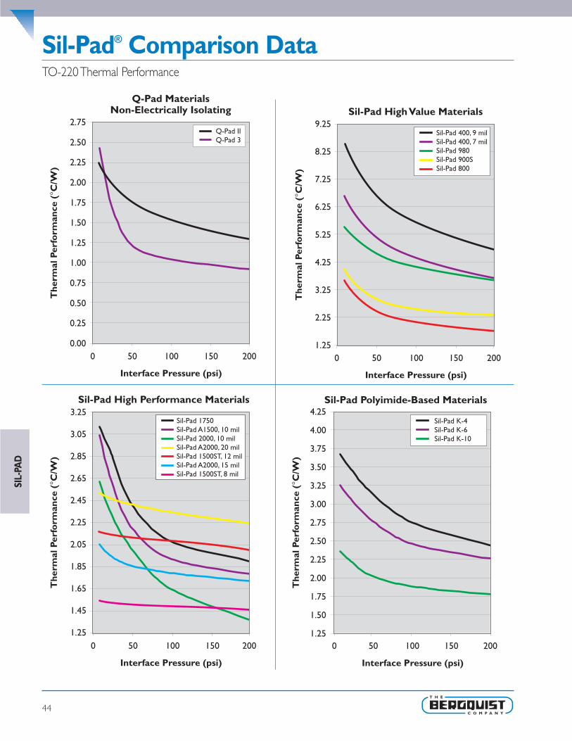
Sil-Pad® Comparison Data
44
SIL-
PAD
TO-220 Thermal Performance
The
rmal
Per
form
ance
(°C
/W)
Interface Pressure (psi)
Sil-Pad High Performance Materials
0 50 100 150 200
3.25
3.05
2.85
2.65
2.45
2.25
2.05
1.85
1.65
1.45
1.25
Sil-Pad 1750Sil-Pad A1500, 10 milSil-Pad 2000, 10 milSil-Pad A2000, 20 milSil-Pad 1500ST, 12 milSil-Pad A2000, 15 milSil-Pad 1500ST, 8 mil
0.00
0.25
0.50
0.75
1.00
1.25
1.50
1.75
2.00
2.25
2.50
2.75
0 50 100 150 200
The
rmal
Per
form
ance
(°C
/W)
Interface Pressure (psi)
Q-Pad Materials Non-Electrically Isolating
Q-Pad IIQ-Pad 3
1.25
2.25
3.25
4.25
5.25
6.25
7.25
8.25
9.25
0 50 100 150 200
The
rmal
Per
form
ance
(°C
/W)
Interface Pressure (psi)
Sil-Pad High Value Materials
Sil-Pad 400, 9 milSil-Pad 400, 7 milSil-Pad 980Sil-Pad 900SSil-Pad 800
Sil-Pad Polyimide-Based Materials4.25
4.00
3.75
3.50
3.25
3.00
2.75
2.50
2.25
2.00
1.75
1.50
1.25
The
rmal
Per
form
ance
(°C
/W)
Interface Pressure (psi)
0 50 100 150 200
Sil-Pad K-4Sil-Pad K-6Sil-Pad K-10

Frequently Asked Questions
45
SIL-PAD
Q: What is the primary difference between Sil-Pad A2000and Sil-Pad 2000 products?
A: Sil-Pad A2000 utilizes a different filler package than Sil-Pad 2000.This change results in a more compliant Sil-Pad A2000 materialthat inherently lowers interfacial resistance losses.This reductionin interfacial resistance results in improved overall thermalperformance when measured at lower pressures in standardASTM D5470 and TO-220 testing.
Q: When should I choose Sil-Pad A2000 vs. Sil-Pad 2000for my application?
A: The answer is based on the assumption that the primary designintent is to increase thermal performance. If your applicationutilizes lower clamping pressures (i.e. 10 to 75 psi) you will findthe Sil-Pad A2000 to provide excellent thermal performance. Incontrast, if you are designing for higher clamping pressures (i.e.100 psi or greater), it is likely that you will require the thermalperformance characteristics of the Sil-Pad 2000.
Q: Are there differences in electrical characteristicsbetween Sil-Pad A2000 and Sil-Pad 2000?
A: Yes. Bergquist evaluates and publishes voltage breakdown, dielectricconstant and volume resistivity data per ASTM standards forthese materials. Due to differences between ASTM lab testingand actual application performance, for best results, these charac-teristics should be evaluated within the actual customer system.
Q: Can I get Sil-Pad A2000 in sheet form?A: Yes.With the new environmentally “green” process improvements
added with the introduction of Sil-Pad A2000 products, thematerials are now available in roll form.The original Sil-Pad 2000material cannot be produced in continuous roll form.
Q: When should I choose Sil-Pad 800 versus Sil-Pad 900for my application?
A: Sil-Pad 800 is specifically formulated to provide excellent thermalperformance for discrete semiconductor applications that utilizelow clamping pressures (i.e. spring clips at 10 to 50 psi). In contrast,if you are designing for higher clamping pressure applicationsusing discrete semi-conductors (i.e. 50 to 100 psi), it is likely thatyou will prefer the combination of high thermal performance andcut-thru resistance inherent in Sil-Pad 900 material.
Q: When should I choose Sil-Pad 980 versus Sil-Pad P900for my application?
A: Sil-Pad 980 is specifically formulated to provide superior cut-thruand crush resistance in combination with excellent heat transferand dielectric properties. Sil-Pad 980 has a proven history ofreliability in high-pressure applications where surface imperfectionssuch as burrs and dents are inherently common.These applicationsoften include heavily machined metal surfaces manufactured fromextrusions or castings. Sil-Pad 900 carries a high level of crushresistance and is more likely to be used in burr-free or controlledsurface finish applications.
Q: Is there an adhesive available for the Sil-Pad 1500ST?A: Sil-Pad 1500ST has an inherent tack on both side of the material.
This inherent tack is used instead of an adhesive.The tackprovides sufficient adhesive for dispensing from the carrier linerand placement on the component. Sil-Pad 1500ST can berepositioned after the initial placement.
Q: Why is the thermal performance curve of the Sil-Pad1500ST so flat when compared to other Sil-Pads?
A: Sil-Pad 1500ST wets out the application surfaces at a very lowpressure. Optimal thermal performance is achieved at pressuresas low as 50 psi.
Q: How do I know which Sil-Pad is right for my specificapplication?
A: Each application has specific characteristics (e.g. surface finish,flatness tolerances, high pressure requirements, potential burrs,etc.) that determine which Sil-Pad will optimize thermalperformance. Select a minimum of two pads that best fit theapplication and then conduct testing to determine whichmaterial performs the best.
Q: What is QS 9000?A: QS9000 defines the fundamental quality system expectations of
North American Automotive Manufacturers and other subscribingcompanies for internal and external suppliers of production andservice parts and materials.These companies are committed toworking with suppliers to ensure customer satisfaction beginningwith conformance to quality requirements, and continuing withreduction of variation and waste of benefit to the final customer,the supply base, and themselves.

Polyimide FilmsPolyimide films can also be used as insulators and are often combinedwith wax or grease to achieve a low thermal impedance.These polyimidefilms are especially tough and have high dielectric strength. Sil-Pad K-4,K-6 and K-10 incorporate polyimide film as the carrier material.
Ceramic InsulatorsOther insulation materials include ceramic wafer insulators which havehigher thermal conductivity than mica.They are often used thicker(20-60 mils), (.5 to 1.5 mm) to reduce capacitive coupling whilemaintaining a low thermal impedance.
Drawbacks to ceramic insulators are high cost and they are rigid likemica and crack easily.Also, ceramic beryllia use requires careful handlingsince inhalation of beryllia dust can cause lung inflammation (berylliosis).
Why Choose Sil-Pad Thermally Conductive Insulators?
46
SIL-
PAD
OverviewThe Bergquist Company established the standard for elastomericthermally conductive insulation materials with the development ofSil-Pad over 20 years ago. Sil-Pad was developed as a clean, grease-free alternative to mica and grease. Now, a complete family of materialsis available to meet the diverse and changing requirements of today’sdesign engineer.
Mica and Grease Mica insulators have been in use for over 30 years and are stillcommonly used as an insulator. Mica is inexpensive and has excellentdielectric strength, but it is brittle and is easily cracked or broken.Because mica used by itself has high thermal impedance, thermalgrease is commonly applied to it.The grease flows easily and excludesair from the interface to reduce the interfacial thermal resistance. Ifthe mica is also thin (2-3 mils [50-80 µm]), a low thermal impedancecan be achieved.
However, thermalgrease introduces anumber of problems tothe assembly process. Itis time-consuming toapply, messy, and difficultto clean. Once thermalgrease has been appliedto an electronic assem-bly, solder processesmust be avoided toprevent contaminationof the solder. Cleaningbaths must also be avoided to prevent wash-out of the interfacegrease, causing a dry joint and contamination of the bath. Assembly,soldering and cleaning processes must be performed in one processwhile the greased insulators are installed off-line in a secondaryprocess. If the grease is silicone based, migration of silicone moleculesoccurs over time, drying out the grease and contaminating the assembly.Silicone migration onto electrical contacts can result in the loss ofelectrical conductance. For this reason, silicone based thermal greasehas not been used in telecommunications systems.

47
SIL-PAD
Carriers The carrier provides physical reinforcement and contributes to dielectricstrength. High dielectric and physical strength is obtained by using aheavy, tight mesh, but thermal resistance will suffer. A light, open meshreduces thermal resistance, dielectric strength and cut-through resistance.The carrier materials used in Sil-Pad materials include fiberglass, dielectricfilm and polyester film which is used in Poly-Pad materials.
FillersThe thermal conductivity of Sil-Pad products is improved by fillingthem with ingredients of high thermal conductivity.The fillers changethe characteristics of the silicone rubber to enhance thermal and/orphysical characteristics.
For instance, some fillers make the silicone rubber hard and toughwhile still retaining the ability to flow under pressure. A harder siliconehelps the material resist cut-through. In other applications a filler isused to make the silicone rubber softer and more conformable torough surfaces.While the range in thermal resistance of greased micais quite large, the average is comparable to elastomeric insulators filledwith a blend of the appropriate ingredients.
Fiberglass-based insulators (Sil-Pad 400 and Sil-Pad 1500) have a roughsurface texture and will show a 15-20% decrease in thermal resistanceover a 24 hour period. Film based insulators (Sil-Pad K-4, Sil-Pad K-6 andSil-Pad K-10) are smoother initially and show a 5% decrease over thesame period of time.
Sil-Pad MaterialsSil-Pad thermally conductive insulators are designed to be clean,grease-free and flexible.The combination of a tough carrier materialsuch as fiberglass and silicone rubber which is conformable, providesthe engineer with a more versatile material than mica or ceramicsand grease. Sil-Pad products minimize the thermal resistance from thecase of a power semiconductor to the heat sink. Sil-Pad materialselectrically isolate the semiconductor from the heat sink and havesufficient dielectric strength to withstand high voltage.They are alsotough enough to resist puncture by the facing metal surface.Withmore than 30 different Sil-Pad materials available, there is a Sil-Padmatched to almost any application.
Sil-Pad ConstructionSil-Pad products are constructed with a variety of different materialsincluding fiberglass, silicone rubber, polyimide film, polyester film andfillers used to enhance performance. Sil-Pad materials are typicallyconstructed with an elastomeric binder compounded with a thermallyconductive filler coated on a carrier.The characteristics of yourapplication often determine which Sil-Pad construction will producethe best performance.
BindersMost Sil-Pad products use silicone rubber as the binder. Silicone rubberhas a low dielectric constant, high dielectric strength, good chemicalresistance and high thermal stability.
Silicone rubber also exhibits cold flow, which excludes air from theinterface as it conforms to the mating surfaces.This flow eliminatesthe need for thermal grease. A rough surface textured insulator needsto flow more to exclude air than a smooth one.The smoother padsalso need less pressure to wet out the surfaces and obtain optimumthermal contact.

Mechanical,Electrical and Thermal Properties
48
SIL-
PAD
Devices with larger surface areas need more pressure to get theinsulator to conform to the interface than smaller devices. In mostscrew mount applications, the torque required to tighten the fastener issufficient to generate the pressure needed for optimum thermal resist-ance.There are exceptions where the specified torque on the fastenerdoes not yield the optimum thermal resistance for the insulator being
used and either a different insulator or a differentmounting scheme should be used.
Interfacial thermal resistance decreases as timeunder pressure increases. In applications wherehigh clamping forces cannot be used, time can besubstituted for pressure to achieve lower thermalresistance.The only way to know precisely what thethermal resistance of an insulator will be in anapplication is to measure it in that application.
Electrical PropertiesIf your application does not require electrical insulation, Q-Pad II orQ-Pad 3 are ideal grease replacement materials.These materials donot provide electrical isolation but have excellent thermal properties.Hi-Flow phase change materials should also be considered for theseapplications. (Reference pages 30-42 of this guide.)
The most important electrical property in a typical assembly where aSil-Pad insulator is used is dielectric strength. In many cases the dielectricstrength of a Sil-Pad will be the determining factor in the design ofthe apparatus in which it is to be used.
Here are some general guidelines regarding electrical properties toconsider when selecting a Sil-Pad material:
• Q-Pad II and Q-Pad 3 are used when electrical isolation is notrequired.
• Dielectric breakdown voltage is the total voltage that a dielectricmaterial can withstand.When insulating electrical components fromeach other and ground, it is desirable to use an insulator with a highbreakdown voltage.
Mechanical PropertiesWoven fiberglass and films are used in Sil-Pad products to providemechanical reinforcement.The most important mechanical propertyin Sil-Pad applications is resistance to cut-through to avoid electricalshorting from the device to the heat sink.
Cut-Through Resistance - Bergquist introduced its TO-220 cut-through testto help customers better understand typical application performance.
Mounting Techniques & Mounting PressureTypical mounting techniques include:
• A spring clip, which exerts a centralized clamping force on the bodyof the transistor.The greater the mounting force of the spring, thelower the thermal resistance of the insulator.
• A screw in the mounting tab.With a screw-mounted TO-220, theforce on the transistor is determined by the torque applied to thefastener.
In extremely low pressure applications, an insulator with pressuresensitive adhesive on each side may give the lowest thermal resistancesince the adhesive wets out the interface easier than the dry rubber.This decreases the interfacial thermal resistance.
SIL-PAD TYPICAL ELECTRICAL PROPERTIESBREAKDOWN
VOLTAGEDIELECTRICSTRENGTH
DIELECTRICCONSTANT
VOLUMERESISTIVITY
Material (kV) (Volts/mil) (kV/mm) (Ohm-Meter)Sil-Pad 400 - 0.007 5 700 18 5.5 1011
Sil-Pad 400 - 0.009 7 800 20 5.5 1011
Sil-Pad A1500 6 700 18 7.0 1011
Sil-Pad 2000 12 800 20 4.0 1011
Sil-Pad K-4 7 1200 30 5.0 1012
Sil-Pad K-6 7 1200 30 4.0 1012
Sil-Pad K-10 7 1200 30 3.7 1012
Test Method ASTM D149** Method A,Type 3
Electrodes
ASTM D149** Method A,Type 3 Electrodes
ASTM D150 ASTM D257

49
SIL-PAD
• Breakdown voltage decreases as the area of the electrodesincreases.This area effect is more pronounced as the thickness ofthe insulator decreases.
• Breakdown voltage decreases as temperature increases.
• Breakdown voltage decreases as humidity increases (Sil-Pad 1750 isless sensitive to moisture).
• Breakdown voltage decreases in the presence of partial discharge.
• Breakdown voltage decreases as the size of the voltage source (kVArating) increases.
• Breakdown voltage can be decreased by excessive mechanical stresson the insulator.
Dielectric strength, dielectric constant and volume resistivity shouldall be taken into consideration when selecting a Sil-Pad material.If your application requires specific electrical performance pleasecontact a Bergquist sales representative for more detailedtesting information.
Thermal Properties The thermal properties of a Sil-Pad material and your requirements forthermal performance probably have more to do with your selection of aSil-Pad than any other factor.
Discrete semiconductors, under normal operating conditions, dissipatewaste power which raises the junction temperature of the device. Unlesssufficient heat is conducted out of the device, its electrical performanceand parameters are changed. A 10°C rise in junction temperature canreduce the mean-time-to-failure of a device by a factor of two. Also,
above 25°C, the semiconductor's total power handling capability will bereduced by a derating factor inherent to the device.
The thermal properties of Sil-Pad products are thermal impedance,thermal conductivity and thermal resistance. The thermal resistanceand conductivity of Sil-Pad products are inherent to the material anddo not change.Thermal resistance and thermal conductivity aremeasured per ASTM D5470 and do not include the interfacial thermalresistance effects.Thermal impedance applies to the thermal transfer inan application and includes the effects of interfacial thermal resistance.As the material is applied in different ways the thermal impedance valueswill vary from application to application.
• The original Sil-Pad material, Sil-Pad 400 continues to be Bergquist'smost popular material for many applications.
• Sil-Pad A1500 is chosen when greater thermal performance isrequired. Sil-Pad A2000 is ideal for high performance, high reliabilityapplications.
Beyond these standard materials many things can contribute to theselection of the correct material for a particular application. Questionsregarding the amount of torque and clamping pressure are oftenasked when selecting a Sil-Pad material. Here are some guidelines:
• Interfacial thermal resistance decreases as clamping pressure increases.
• The clamping pressure required to minimize interfacial thermalresistance can vary with each type of insulator.
• Sil-Pad products with smooth surface finishes (Sil-Pad A1500, Sil-PadA2000, Sil-Pad K-4, Sil-Pad K-6 and Sil-Pad K-10) are less sensitive toclamping pressure than Sil-Pads with rough surface finishes (Sil-Pad 400).

Sil-Pad® Thermally Conductive
50
SIL-
PAD
Sil-Pad 400.007 in.
Sil-Pad 4000.009 in.
Sil-Pad800
Sil-Pad900S
Sil-Pad980
Sil-PadA1500
Color Gray Gray Gold Pink Mauve Green
Thickness (in/mm) .007 ± .001(.18 ± .025)
.009 ± .001(.23 ± .025)
.005 ± .001(.13 ± .025)
.0097 ± .001(.23 ± .025)
.009 ± .001(.23 ± .025)
.010 ± .001(.25 ± .025)
Thermal PerformanceTO-220 Test @ 50 psi °C/W 5.14 6.61 2.45 2.90 4.52 2.21
Thermal Impedance (°C-in2/W) 1.13 1.45 0.45 0.61 1.07 0.42
Thermal Conductivity (W/m-K nominal) 0.9 0.9 1.6 1.6 1.2 2.0
Voltage Breakdown (Vac) 3500 4500 1700 5500 4000 6000
Continuous Use Temperature (°C) -60 to 180 -60 to 180 -60 to 180 -60 to 180 -40 to 180 -60 to 180
Construction Silicone/Fiberglass
Silicone/Fiberglass
Silicone/Fiberglass
Silicone/Fiberglass
Silicone/Fiberglass
Silicone/Fiberglass
Sil-Pad Applications
Here, Sil-Pad 900 enhances thethermal transfer from this FR-4circuit board with thermal vias tothe metal base plate.
Sil-Pad is available in over onehundred standard configurationsfor common JEDEC packageoutlines.
The circuit board above showspunched parts interfacing screw-mounted transistors to a finnedheat sink.
This application uses Sil-Pad toisolate the mounting brackets fromthe assembly frame.
A common Sil-Pad applicationincludes TO-220 transistorsmounted in a row on a heat rail.
These Sil-Pad applications showclip mounting of transistors on theleft and screw mounting to an alu-minum bracket on the right.
Choose a Sil-Pad that optimizesthermal performance for ourmounting method — screw, clip,spring, bar, and so on.
Sil-Pad 980 is used extensively inindustrial applications havingexcellent cut-through and abrasionresistance.

Insulator Selection Guide
51
SIL-PAD
Sil-Pad1500ST
Sil-PadA2000
Sil-PadK-4
Sil-PadK-6
Sil-PadK-10
Poly-Pad1000
Poly-PadK-4
Poly-PadK-10
TestMethod
Blue White Gray Bluegreen Beige Yellow Mauve Yellow Visual
.008 — .001(.20 ± .025)
.015 ± .001(.38 ± .025)
.006 ± .001(.15 ± .025)
.006 ± .001(.15 ± .025)
.006 ± .001(.15 ± .025)
.009 ± .001(.23 ± .025)
.006 ± .001(.15 ± .025)
.006 ± .001(.15 ± .025) ASTM D374
1.51 1.86 3.13 2.76 2.01 3.74 4.34 2.75 ASTM D5470
0.23 0.32 0.48 0.49 0.41 0.82 0.95 0.60 ASTM D5470
1.8 3.0 0.9 1.1 1.3 1.2 0.9 1.3 ASTM D5470
3000 4000 6000 6000 6000 2500 6000 6000 ASTM D149
-60 to 180 -60 to 200 -60 to 180 -60 to 180 -60 to 180 -20 to 150 -20 to 150 -30 to 120 —
Silicone/Fiberglass
Silicone/Fiberglass
Silicone/Film
Silicone/Film
Silicone/Film
Polyester/Fiberglass
Polyester/Film
Polyester/Film —
Sil-Pad Comparison Made Simple!
Comparing thermally conductiveinterface materials has never beeneasier. Simply go to the “ThermalMaterials” section of the Bergquistwebsite (www.bergquistcompany.com),and select “Compare MaterialProperties.”Then select up to threeseparate products and this handycomparison tool will automaticallychart thermal resistance values anddisplay a material properties table ofselected materials.
The materials comparison tool canbe used for most Bergquist thermalmaterials, including Sil-Pad, Hi-Flow,Gap Pad, Q-Pad, Bond-Ply andLiqui-Bond products.

Sil-Pad® 400The Original Sil-Pad Material
52
Features and Benefits• Thermal impedance:
1.13°C-in2/W (@50 psi)
• Original Sil-Pad material
• Excellent mechanical and physicalcharacteristics
• Flame retardant
Sil-Pad 400 is a composite of silicone rubberand fiberglass. It is flame retardant and isspecially formulated for use as a thermallyconductive insulator. Primary use is to electri-cally isolate power sources from heat sinks.
Sil-Pad 400 has excellent mechanical andphysical characteristics. Surfaces are pliableand allow complete surface contact withexcellent heat dissipation. Sil-Pad 400 actuallyimproves its thermal resistance with age.Thereinforcing fiberglass gives excellent cut-throughresistance and Sil-Pad 400 is non-toxic andresists damage from cleaning agents.
Typical Applications Include:• Power supplies • Automotive electronics • Motor controls
• Power semiconductors • U.L. File Number E59150 • FSCM Number 55285
• Military Specifications:- MIL-M-38527/8A - MIL-M-38527C - MIL-I-49456 - MIL-M-87111
Configurations Available:• Sheet form, die-cut parts, and roll form; with or without pressure sensitive adhesive
Building a Part Number Standard Options
Note: To build a part number, visit our website at www.bergquistcompany.com.Sil-Pad® U.S. Patents 4,574,879; 4,602,125; 4,602,678; 4,685,987; 4,842,911 and others
SIL-
PAD
SP400 - 0.007 - AC - 12/250 - NA �example
NA = Selected standard option. If not selecting astandard option, insert company name, drawingnumber, and revision level.
_ _ _ = Std. configuration dash number, 1212 = 12"X 12" sheets, 12/250 = 12" X 250' rolls,00 = custom configuration
AC = Adhesive one side, AC2 = Adhesive bothsides, 00 = no adhesive
Standard Thicknesses Available: 0.007", 0.009"
SP400 = Sil-Pad 400
Sect
ion
A
S ect
ion
B
Sect
ion
C
S ect
ion
E
Sect
ion
D
TYPICAL PROPERTIES OF SIL-PAD 400PROPERTY IMPERIAL VALUE METRIC VALUE TEST METHODColor Gray Gray Visual
Reinforcement Carrier Fiberglass Fiberglass —
Thickness (inch) / (mm) 0.007, 0.009 0.178, 0.229 ASTM D374
Hardness (Shore A) 85 85 ASTM D2240
Breaking Strength (lbs/inch) / (kN/m) 100 18 ASTM D1458
Elongation (%45° to Warp & Fill) 40 40 ASTM D412
Tensile Strength (psi) / (MPa) 3000 20 ASTM D412
Continuous Use Temp (°F) / (°C) -76 to 356 -60 to 180 —
ELECTRICALDielectric Breakdown Voltage (Vac) 3500, 4500 3500, 4500 ASTM D149
Dielectric Constant (1000 Hz) 5.5 5.5 ASTM D150
Volume Resistivity (Ohm-meter) 1011 1011 ASTM D257
Flame Rating 94 V-O 94 V-O U.L.
THERMALThermal Conductivity (W/m-K) 0.9 0.9 ASTM D5470
THERMAL PERFORMANCE vs PRESSUREPressure (psi) 10 25 50 100 200
TO-220 Thermal Performance (°C/W) 0.007" 6.62 5.93 5.14 4.38 3.61
TO-220 Thermal Performance (°C/W) 0.009" 8.51 7.62 6.61 5.63 4.64
Thermal Impedance (°C-in2/W) 0.007" (1) 1.82 1.42 1.13 0.82 0.54
Thermal Impedance (°C-in2/W) 0.009" (1) 2.34 1.83 1.45 1.05 0.69
1) The ASTM D5470 (Bergquist modified) test fixture was used and the test sample was conditioned at 70°C prior to test.Therecorded value includes interfacial thermal resistance.These values are provided for reference only. Actual application performance isdirectly related to the surface roughness, flatness and pressure applied.

Sil-Pad® 800
Features and Benefits• Thermal impedance:
0.45°C-in2/W (@50 psi)
• Low mounting pressures
• Smooth and highly compliant surface
• Electrically isolating
The Sil-Pad 800 family of thermally conductiveinsulation materials is designed for applicationsrequiring high thermal performance andelectrical isolation.These applications alsotypically have low mounting pressures forcomponent clamping.
Sil-Pad 800 material combines a smooth andhighly compliant surface characteristic with highthermal conductivity.These features optimize thethermal resistance properties at low pressure.
Applications requiring low component clampingforces include discrete semiconductors(TO-220,TO-247 and TO-218) mounted withspring clips. Spring clips assist with quick assemblybut apply a limited amount of force to thesemiconductor.The smooth surface textureof Sil-Pad 800 minimizes interfacial thermalresistance and maximizes thermal performance.
High Performance Insulator for Low Pressure Applications
53
Typical Applications Include:• Power supplies
• Automotive electronics
• Motor controls
• Power semiconductors
Configurations Available:• Sheet form, die-cut parts, and roll form
• With or without pressure sensitive adhesive
Building a Part Number Standard Options
Note: To build a part number, visit our website at www.bergquistcompany.com.
Sil-Pad®: U.S. Patents 4,574,879; 4,602,125; 4,602,678; 4,685,987; 4,842,911 and others
SIL-PAD
SP800 - 0.005 - AC - 1212 - NA �example
NA = Selected standard option. If not selecting astandard option, insert company name, drawingnumber, and revision level.
_ _ _ = Std. configuration dash number, 1212 = 12"X 12" sheets, 12/250 = 12" X 250' rolls,00 = custom configuration
AC = Adhesive one side, 00 = no adhesive
Standard Thicknesses Available: 0.005"
SP800 = Sil-Pad 800
Sect
ion
A
Sect
ion
B
Sect
ion
C
Sect
ion
E
Sect
ion
D
TYPICAL PROPERTIES OF SIL-PAD 800PROPERTY IMPERIAL VALUE METRIC VALUE TEST METHODColor Gold Gold Visual
Reinforcement Carrier Fiberglass Fiberglass —
Thickness (inch) / (mm) 0.005 0.127 ASTM D374
Hardness (Shore A) 91 91 ASTM D2240
Elongation (%45° to Warp & Fill) 20 20 ASTM D412
Tensile Strength (psi) / (MPa) 1700 12 ASTM D412
Continuous Use Temp (°F) / (°C) -76 to 356 -60 to 180 —
ELECTRICALDielectric Breakdown Voltage (Vac) 1700 1700 ASTM D149
Type 3 Electrodes 3000 3000 ASTM D149
Dielectric Constant (1000 Hz) 6.0 6.0 ASTM D150
Volume Resistivity (Ohm-meter) 1010 1010 ASTM D257
Flame Rating 94 V-O 94 V-O U.L.
THERMALThermal Conductivity (W/m-K) 1.6 1.6 ASTM D5470
THERMAL PERFORMANCE vs PRESSUREPressure (psi) 10 25 50 100 200
TO-220 Thermal Performance (°C/W) 3.56 3.01 2.45 2.05 1.74
Thermal Impedance (°C-in2/W) (1) 0.92 0.60 0.45 0.36 0.29
1) The ASTM D5470 (Bergquist modified) test fixture was used and the test sample was conditioned at 70°C prior to test.Therecorded value includes interfacial thermal resistance.These values are provided for reference only. Actual application performance isdirectly related to the surface roughness, flatness and pressure applied.

Sil-Pad® 900SHigh Performance Insulator for Low Pressure Applications
54
Features and Benefits• Thermal impedance:
0.61°C-in2/W (@50 psi)
• Low mounting pressures
• Smooth and highly compliant surface
• Electrically isolating
The Sil-Pad 900S family of thermally conductiveinsulation materials is designed for applicationsrequiring high thermal performance andelectrical isolation.These applications alsotypically have low mounting pressures forcomponent clamping.
Sil-Pad 900S material combines a smoothand highly compliant surface characteristicwith high thermal conductivity.Thesefeatures optimize the thermal resistanceproperties at low pressure.
Applications requiring low component clampingforces include discrete semiconductors(TO-220,TO-247 and TO-218) mounted withspring clips. Spring clips assist with quickassembly but apply a limited amount of forceto the semiconductor.The smooth surfacetexture of Sil-Pad 900S minimizes interfacialthermal resistance and maximizes thermalperformance.
Typical Applications Include:• Power supplies
• Automotive electronics
• Motor controls
• Power semiconductors
Configurations Available:• Sheet form, die-cut parts, and roll form
• With or without pressure sensitive adhesive
Building a Part Number Standard Options
Note: To build a part number, visit our website at www.bergquistcompany.com.
Sil-Pad®: U.S. Patents 4,574,879; 4,602,125; 4,602,678; 4,685,987; 4,842,911 and others
SIL-
PAD
SP900S - 0.009 - AC - 00 - Acme 951753 Rev. B �example
NA = Selected standard option. If not selecting astandard option, insert company name, drawingnumber, and revision level.
_ _ _ = Std. configuration dash number, 1212 = 12"X 12" sheets, 12/250 = 12" X 250' rolls,00 = custom configuration
AC = Adhesive one side, 00 = no adhesive
Standard Thicknesses Available: 0.009"
SP900S = Sil-Pad 900S
Sect
ion
A
Sect
ion
B
S ec t
ion
C
Sect
ion
E
Sec t
ion
D
TYPICAL PROPERTIES OF SIL-PAD 900SPROPERTY IMPERIAL VALUE METRIC VALUE TEST METHODColor Pink Pink Visual
Reinforcement Carrier Fiberglass Fiberglass —
Thickness (inch) / (mm) 0.009 0.229 ASTM D374
Hardness (Shore A) 92 92 ASTM D2240
Elongation (%45° to Warp & Fill) 20 20 ASTM D412
Tensile Strength (psi) / (MPa) 1300 9 ASTM D412
Continuous Use Temp (°F) / (°C) -76 to 356 -60 to 180 —
ELECTRICALDielectric Breakdown Voltage (Vac) 5500 5500 ASTM D149
Type 3 Electrodes 8300 8300 ASTM D149
Dielectric Constant (1000 Hz) 6.0 6.0 ASTM D150
Volume Resistivity (Ohm-meter) 1010 1010 ASTM D257
Flame Rating 94 V-O 94 V-O U.L.
THERMALThermal Conductivity (W/m-K) 1.6 a1.60.61 ASTM D5470
THERMAL PERFORMANCE vs PRESSUREPressure (psi) 10 25 50 100 200
TO-220 Thermal Performance (°C/W) 3.96 3.41 2.90 2.53 2.32
Thermal Impedance (°C-in2/W) (1) 0.95 0.75 0.61 0.47 0.41
1) The ASTM D5470 (Bergquist modified) test fixture was used and the test sample was conditioned at 70°C prior to test.Therecorded value includes interfacial thermal resistance.These values are provided for reference only. Actual application performance isdirectly related to the surface roughness, flatness and pressure applied.

Sil-Pad® 980
Features and Benefits• Thermal impedance:
1.07°C-in2/W (@50 psi)
• Excellent cut-through resistance
• Use in screw mounted applications withcut-through problems
Bergquist Sil-Pad 980 is a specially formulatedmaterial with high crush resistance to preventcut through.This material provides thermalconductivity and electrical insulation.
Use Sil-Pad 980 material in screw mountedapplication with cut through problems.TheSil-Pad 980 is Bergquist’s best material for cutthrough resistance.
High Cut-Through Resistant, Electrically Insulative,Thermally Conductive Material
55
SIL-PAD
Typical Applications Include:• Silicone sensitive assemblies
• Telecommunications
• Automotive electronics
Configurations Available:• Sheet form, die-cut parts, and roll form
• With or without pressure sensitive adhesive
Building a Part Number Standard Options
Note: To build a part number, visit our website at www.bergquistcompany.com.
Sil-Pad®: U.S. Patents 4,574,879; 4,602,125; 4,602,678; 4,685,987; 4,842,911 and others
SP980 - 0.009 - AC - 00 - Acme 951753 Rev. B �example
NA = Selected standard option. If not selecting astandard option, insert company name, drawingnumber, and revision level.
_ _ _ = Std. configuration dash number, 1212 = 12"X 12" sheets, 12/250 = 12" X 250' rolls,00 = custom configuration
AC = Adhesive one side, 00 = no adhesive
Standard Thicknesses Available: 0.009"
SP980 = Sil-Pad 980
Sect
ion
A
Sect
ion
B
Sect
ion
C
Sect
ion
E
Sect
ion
D
TYPICAL PROPERTIES OF SIL-PAD 980PROPERTY IMPERIAL VALUE METRIC VALUE TEST METHODColor Mauve Mauve Visual
Reinforcement Carrier Fiberglass Fiberglass —
Thickness (inch) / (mm) 0.009 0.229 ASTM D374
Hardness (Shore A) 95 95 ASTM D2240
Breaking Strength (lbs/inch) / (kN/m) 140 26 ASTM D1458
Elongation (%45° to Warp & Fill) 10 10 ASTM D412
Cut-Through (lbs) / (kg) 750 340 ASTM D412
Continuous Use Temp (°F) / (°C) -40 to 302 -40 to 150 —
ELECTRICALDielectric Breakdown Voltage (Vac) 4000 4000 ASTM D149
Dielectric Constant (1000 Hz) 3.5 3.5 ASTM D150
Volume Resistivity (Ohm-meter) 1010 1010 ASTM D257
THERMALThermal Conductivity (W/m-K) (1) 1.2 1.2 ASTM D5470
THERMAL PERFORMANCE vs PRESSUREPressure (psi) 10 25 50 100 200
TO-220 Thermal Performance (°C/W) 5.48 5.07 4.52 4.04 3.56
Thermal Impedance (°C-in2/W) (2) 1.51 1.22 1.07 0.89 0.53
1) The ASTM D5470 (Bergquist modified) test fixture was used and the test sample was conditioned at 70°C prior to test.Therecorded value includes interfacial thermal resistance.These values are provided for reference only. Actual application performance isdirectly related to the surface roughness, flatness and pressure applied.

Sil-Pad® A1500Electrically Insulating,Thermally Conductive Elastomeric Material
56
Features and Benefits• Thermal impedance:
0.42°C-in2/W (@50 psi)
• Solvent-free process
• Elastomeric compound coated onboth sides
Bergquist Sil-Pad A1500 is a silicone-basedthermally conductive and electrically insulatingmaterial. It consists of a cured siliconeelastomeric compound coated on both sidesof a fiberglass reinforcement layer.
Sil-Pad A1500 is a product of similar perform-ance to the Sil-Pad 1500 manufactured witha more environmentally friendly, solvent-freeprocess.
Typical Applications Include:• Power supplies
• Automotive electronics
• Motor controls
• Power semiconductors
Configurations Available:• Sheet form, die-cut parts, and roll form (maximum recommended roll width is 10 inches)
• With or without pressure sensitive adhesive
Building a Part Number Standard Options
Note: To build a part number, visit our website at www.bergquistcompany.com.
Sil-Pad®: U.S. Patents 4,574,879; 4,602,125; 4,602,678; 4,685,987; 4,842,911 and others
SIL-
PAD
SPA1500 - 0.010 - AC - 12/250 - NA �example
NA = Selected standard option. If not selecting astandard option, insert company name, drawingnumber, and revision level.
_ _ _ = Std. configuration dash number, 1212 = 12"X 12" sheets, 12/250 = 12" X 250' rolls,00 = custom configuration
AC = Adhesive one side, 00 = no adhesive
Standard Thicknesses Available: 0.010"
SPA1500 = Sil-Pad A1500
Sect
ion
A
Sect
ion
B
Sect
ion
C
Sect
ion
E
Sect
ion
D
TYPICAL PROPERTIES OF SIL-PAD A1500PROPERTY IMPERIAL VALUE METRIC VALUE TEST METHODColor Green Green Visual
Reinforcement Carrier Fiberglass Fiberglass —
Thickness (inch) / (mm) 0.010 0.254 ASTM D374
Hardness (Shore A) 80 80 ASTM D2240
Breaking Strength (lbs/inch) / (kN/m) 65 12 ASTM D1458
Elongation (%45° to Warp & Fill) 40 40 ASTM D412
Continuous Use Temp (°F) / (°C) -76 to 356 -60 to 180 —
ELECTRICALDielectric Breakdown Voltage (Vac) 6000 6000 ASTM D149
Dielectric Constant (1000 Hz) 7.0 7.0 ASTM D150
Volume Resistivity (Ohm-meter) 1011 1011 ASTM D257
Flame Rating 94 V-O 94 V-O U.L.
THERMALThermal Conductivity (W/m-K) 2.0 2.0 ASTM D5470
THERMAL PERFORMANCE vs PRESSUREPressure (psi) 10 25 50 100 200
TO-220 Thermal Performance (°C/W) 3.03 2.62 2.21 1.92 1.78
Thermal Impedance (°C-in2/W) (1) 0.59 0.50 0.42 0.34 0.31
1) The ASTM D5470 (Bergquist modified) test fixture was used and the test sample was conditioned at 70°C prior to test.Therecorded value includes interfacial thermal resistance.These values are provided for reference only. Actual application performance isdirectly related to the surface roughness, flatness and pressure applied.

Sil-Pad® 1500ST
Features and Benefits• Thermal impedance:
0.30°C-in2/W (@50 psi)
• Inherent surface tack on both sides
• Pad is re-positionable
• Excellent thermal performance
• Auto-placement and dispensable
Bergquist Sil-Pad 1500ST (Soft Tack) is a fiber-glass reinforced thermal interface materialthat has an inherent tack on both sides.Sil-Pad 1500ST exhibits superior thermalperformance when compared to thecompetitors’ thermal interface materials.Sil-Pad 1500ST is supplied in roll form forexceptional auto-dispensing and auto-placement in high volume assemblies. Sil-Pad1500ST is intended for placement betweenelectronic power devices and its heat sink.
Electrically Insulating,Thermally Conductive, Soft-Tack Elastomeric Material
57
Typical Applications Include:• Power supplies
• Automotive electronics
• Motor controls
Configurations Available:• Die-cut parts and slit-to-width, roll form
• Also available in 12 mil thickness
Building a Part Number Standard Options
Note: To build a part number, visit our website at www.bergquistcompany.com.
Sil-Pad®: U.S. Patents 4,574,879; 4,602,125; 4,602,678; 4,685,987; 4,842,911 and others
SIL-PAD
SP1500ST - 0.010 - AC - 1012 - ACME10256 Rev. a �example
NA = Selected standard option. If not selecting astandard option, insert company name, drawingnumber, and revision level.
_ _ _ = Std. configuration dash number, 1012 = 10"X 12" sheets, 10/250 = 10" X 250' rolls,00 = custom configuration
AC = Adhesive one side, 00 = no adhesive
Standard Thicknesses Available: 0.010"
SP1500ST = Sil-Pad 1500ST
Sect
ion
A
Sect
ion
B
Sect
ion
C
Sect
ion
E
Sect
ion
D
TYPICAL PROPERTIES OF SIL-PAD 1500STPROPERTY IMPERIAL VALUE METRIC VALUE TEST METHODColor Blue Blue Visual
Reinforcement Carrier Fiberglass Fiberglass —
Thickness (inch) / (mm) 0.008 0.203 ASTM D374
Hardness (Shore 00) 71 71 ASTM D2240
Breaking Strength (lbs/inch) / (kN/m) 1.9 0.34 ASTM D1458
Elongation (%45° to Warp & Fill) 22 22 ASTM D412
Tensile Strength (psi) / (MPa) 238 1.64 ASTM D412
Continuous Use Temp (°F) / (°C) -76 to 356 -60 to 180 —
ELECTRICALDielectric Breakdown Voltage (Vac) 3000 3000 ASTM D149
Dielectric Constant (1000 Hz) 6.1 6.1 ASTM D150
Volume Resistivity (Ohm-meter) 1011 1011 ASTM D257
Flame Rating 94 V-O 94 V-O U.L.
THERMALThermal Conductivity (W/m-K) 1.8 1.8 ASTM D5470
THERMAL PERFORMANCE vs PRESSUREPressure (psi) 10 25 50 100 200
TO-220 Thermal Performance (°C/W) 1.54 1.52 1.51 1.49 1.46
Thermal Impedance (°C-in2/W) (1) 0.37 0.28 0.23 0.21 0.20
1) The ASTM D5470 (Bergquist modified) test fixture was used and the test sample was conditioned at 70°C prior to test.Therecorded value includes interfacial thermal resistance.These values are provided for reference only. Actual application performance isdirectly related to the surface roughness, flatness and pressure applied.

58
SIL-
PAD
Features and Benefits• Thermal impedance:
0.53°C-in2/W (@50 psi)
• Excellent dielectric strength retention afterhumidity exposure
• Elastomeric pad
The combination of high thermal conductivityand excellent dielectric strength retentionafter humidity exposure is formulated intothe Sil-Pad 1750 elastomeric pad.
Sil-Pad 1750 relies on processes that minimizethe effect of high humidity on the electricalproperties of finished material.Therefore,exposure to humid environments duringassembly, or over long term operatingconditions, will not severely affect the abilityof the material to perform.
Sil-Pad® 1750
Typical Applications Include:• High voltage power supplies
• Motor controls
• High “hi-pot” requirements
Configurations Available:• Sheet form and die-cut parts
• With or without pressure sensitive adhesive
Building a Part Number Standard Options
Note: To build a part number, visit our website at www.bergquistcompany.com.
Sil-Pad®: U.S. Patents 4,574,879; 4,602,125; 4,602,678; 4,685,987; 4,842,911 and others
For High Humidity, High Dielectric (U.L. 1950, IEC 950) Requirements
SP1750 - 0.012 - AC - 12/250 - NA �example
NA = Selected standard option. If not selecting astandard option, insert company name, drawingnumber, and revision level.
_ _ _ = Std. configuration dash number, 1212 = 12"X 12" sheets, 12/250 = 12" X 250' rolls,00 = custom configuration
AC = Adhesive one side, 00 = no adhesive
Standard Thicknesses Available: 0.012"
SP1750 = Sil-Pad 1750
Sect
ion
A
Sect
ion
B
Sect
ion
C
Sect
ion
E
Sect
ion
D
TYPICAL PROPERTIES OF SIL-PAD 1750PROPERTY IMPERIAL VALUE METRIC VALUE TEST METHODColor Green Green Visual
Reinforcement Carrier Fiberglass Fiberglass —
Thickness (inch) / (mm) 0.012 0.305 ASTM D374
Hardness (Shore A) 85 85 ASTM D2240
Breaking Strength (lbs/inch) / (kN/m) 65 12 ASTM D1458
Elongation (%45° to Warp & Fill) 23 23 ASTM D412
Tensile Strength (psi) / (MPa) 1509 10 ASTM D412
Continuous Use Temp (°F) / (°C) -76 to 356 -60 to 180 —
ELECTRICALDielectric Breakdown Voltage (Vac) 6000 6000 ASTM D149
Dielectric Constant (1000 Hz) 1509 10 ASTM D150
Volume Resistivity (Ohm-meter) 1012 1012 ASTM D257
Flame Rating 94 V-O 94 V-O U.L.
THERMALThermal Conductivity (W/m-K) 2.2 2.2 ASTM D5470
THERMAL PERFORMANCE vs PRESSUREPressure (psi) 10 25 50 100 200
TO-220 Thermal Performance (°C/W) 3.11 2.87 2.42 2.08 1.90
Thermal Impedance (°C-in2/W) (1) 0.86 0.68 0.53 0.39 0.28
1) The ASTM D5470 (Bergquist modified) test fixture was used and the test sample was conditioned at 70°C prior to test.Therecorded value includes interfacial thermal resistance.These values are provided for reference only. Actual application performance isdirectly related to the surface roughness, flatness and pressure applied.

59
SIL-PAD
Sil-Pad® 2000Higher Performance, High Reliability Insulator
Features and Benefits• Thermal impedance:
0.33°C-in2/W (@50 psi)
• Complies with military standards
• Optimal heat transfer
• High thermal conductivity 3.5 W/m-K
Sil-Pad 2000 is a high performance thermallyconductive insulator designed for demandingmilitary / aerospace and commercial applica-tions. In these applications, Sil-Pad 2000complies with military standards.
Sil-Pad 2000 is a silicone elastomer formulatedto maximize the thermal and dielectricperformance of the filler/binder matrix.Theresult is a grease-free, conformable material,capable of meeting or exceeding the thermaland electrical requirements of high reliabilityelectronic packaging applications.
Typical Applications Include:• Aerospace
• FSCM Number 55285
• Commercial
• U.L. File Number E59150
• Military Specifications:- MIL-M-38527/8A- MIL-M-38527C- MIL-I-49456
Configurations Available:• Sheet form and die-cut parts, with or without pressure sensitive adhesive.
• Variety of thickness gages to meet customer requirements
Building a Part Number Standard Options
Note: To build a part number, visit our website at www.bergquistcompany.com.
Sil-Pad®: U.S. Patents 4,574,879; 4,602,125; 4,602,678; 4,685,987; 4,842,911 and others
Outgassing Data forSpacecraft Materials
Post CureConditions
% TML(1.0% Max.Acceptable)
%CVCM(0.1% Max.Acceptable)
24 hrs. @ 175°CNo Post Cure
0.070.26
0.030.10
SP2000 - 0.015 - AC - 00 - NA �example
NA = Selected standard option. If not selecting astandard option, insert company name, drawingnumber, and revision level.
_ _ _ = Std. configuration dash number, 1212 = 12"X 12" sheets, 00 = custom configuration
AC = Adhesive one side, 00 = no adhesive
Standard Thicknesses Available: 0.010", 0.015", 0.020"
SP2000 = Sil-Pad 2000
Sect
ion
A
Sect
ion
B
Sect
ion
C
Sect
ion
E
Sect
ion
D
TYPICAL PROPERTIES OF SIL-PAD 2000PROPERTY IMPERIAL VALUE METRIC VALUE TEST METHODColor White White Visual
Reinforcement Carrier Fiberglass Fiberglass —
Thickness (inch) / (mm) 0.010 0.254 ASTM D374
Hardness (Shore A) 90 90 ASTM D2240
Continuous Use Temp (°F) / (°C) -76 to 392 -60 to 200 —
ELECTRICALDielectric Breakdown Voltage (Vac) 4000 4000 ASTM D149
Dielectric Constant (1000 Hz) 4.0 4.0 ASTM D150
Volume Resistivity (Ohm-meter) 1011 1011 ASTM D257
Flame Rating 94 V-O 94 V-O U.L.
THERMALThermal Conductivity (W/m-K) 3.5 3.5 ASTM D5470
THERMAL PERFORMANCE vs PRESSUREPressure (psi) 10 25 50 100 200
TO-220 Thermal Performance (°C/W) 2.61 2.32 2.02 1.65 1.37
Thermal Impedance (°C-in2/W) (1) 0.57 0.43 0.33 0.25 0.20
1) The ASTM D5470 (Bergquist modified) test fixture was used and the test sample was conditioned at 70°C prior to test. Therecorded value includes interfacial thermal resistance. These values are provided for reference only. Actual application performance isdirectly related to the surface roughness, flatness and pressure applied.

60
SIL-
PAD
Features and Benefits• Thermal impedance:
0.32°C-in2/W (@50 psi)
• Optimal heat transfer
• High thermal conductivity: 3.0 W/m-K
Sil-Pad A2000 is a conformable elastomerwith very high thermal conductivity that actsas a thermal interface between electricalcomponents and heat sinks. Sil-Pad A2000 isfor applications where optimal heat transfer isa requirement.
This thermally conductive silicone elastomer isformulated to maximize the thermal anddielectric performance of the filler/bindermatrix.The result is a “grease-free,” conform-able material capable of meeting or exceedingthe thermal and electrical requirements of highreliability electronic packaging applications.
Sil-Pad® A2000Higher Performance, High Reliability Insulator
Typical Applications Include:• Motor drive controls
• Avionics
• High voltage power supplies
• Power transistor / heat sink interface
Configurations Available:• Sheet form and die-cut parts
• With or without pressure sensitive adhesive
• Variety of thickness gages to meet customer requirementsPreferred thickness includes 0.015" and 0.020"
Building a Part Number Standard Options
Note: To build a part number, visit our website at www.bergquistcompany.com.
Sil-Pad®: U.S. Patents 4,574,879; 4,602,125; 4,602,678; 4,685,987; 4,842,911 and others
SPA2000 - 0.015 - 00 - 1212 - NA �example
NA = Selected standard option. If not selecting astandard option, insert company name, drawingnumber, and revision level.
_ _ _ = Std. configuration dash number, 1212 = 12"X 12" sheets, 00 = custom configuration
AC = Adhesive one side, 00 = no adhesive
Standard Thicknesses Available: 0.015", 0.020"
SPA2000 = Sil-Pad A2000
Sect
ion
A
S ect
ion
B
Sect
ion
C
S ect
ion
E
Sect
ion
D
TYPICAL PROPERTIES OF SIL-PAD A2000PROPERTY IMPERIAL VALUE METRIC VALUE TEST METHODColor White White Visual
Reinforcement Carrier Fiberglass Fiberglass —
Thickness (inch) / (mm) 0.015 to 0.020 0.381 to 0.508 ASTM D374
Hardness (Shore A) 90 90 ASTM D2240
Heat Capacity (J/g-K) 1.0 1.0 ASTM C351
Continuous Use Temp (°F) / (°C) -76 to 392 -60 to 200 —
ELECTRICALDielectric Breakdown Voltage (Vac) 4000 4000 ASTM D149
Dielectric Constant (1000 Hz) 7.0 7.0 ASTM D150
Volume Resistivity (Ohm-meter) 1011 1011 ASTM D257
Flame Rating 94 V-O 94 V-O U.L.
THERMALThermal Conductivity (W/m-K) 3.0 3.0 ASTM D5470
THERMAL PERFORMANCE vs PRESSUREPressure (psi) 10 25 50 100 200
TO-220 Thermal Performance (°C/W) 0.015" 2.05 1.94 1.86 1.79 1.72
Thermal Impedance (°C-in2/W) 0.015" (1) 0.53 0.40 0.32 0.28 0.26
1) The ASTM D5470 (Bergquist modified) test fixture was used and the test sample was conditioned at 70°C prior to test.Therecorded value includes interfacial thermal resistance.These values are provided for reference only. Actual application performance isdirectly related to the surface roughness, flatness and pressure applied.

61
SIL-PAD
Sil-Pad® K-4The Original Kapton®-Based Insulator
Features and Benefits• Thermal impedance:
0.48°C-in2/W (@50 psi)
• Withstands high voltages
• High dielectric strength
• Very durable
Sil-Pad K-4 uses a specially developed filmwhich has high thermal conductivity, highdielectric strength and is very durable. Sil-PadK-4 combines the thermal transfer propertiesof well-known Sil-Pad rubber with the physicalproperties of a film.
Sil-Pad K-4 is a durable insulator that with-stands high voltages and requires no thermalgrease to transfer heat. Sil-Pad K-4 is availablein customized shapes and sizes.
Typical Applications Include:• Power supplies • Motor controls
• Power semiconductors • UL FILE NUMBER E59150
• FSCM NUMBER 55285
• Military Specifications- MIL SPEC. MIL-M-38527/8A - MIL-M-38527C- MIL-I-49456 - MIL-M-87111
Configurations Available:• Sheet form, die-cut parts and roll form, with or without pressure sensitive adhesive
Building a Part Number Standard Options
Note: To build a part number, visit our website at www.bergquistcompany.com.
Sil-Pad®: U.S. Patents 4,574,879; 4,602,125; 4,602,678; 4,685,987; 4,842,911 and others.Kapton® is a registered trademark of DuPont.
SPK4 - 0.006" - 00 - 12/250 - NA �example
NA = Selected standard option. If not selecting astandard option, insert company name, drawingnumber, and revision level.
_ _ _ = Std. configuration dash number, 1212 = 12"X 12" sheets, 12/250 = 12" X 250' rolls,00 = custom configuration
AC = Adhesive one side, 00 = no adhesive
Standard Thicknesses Available: 0.006"
SPK4 = Sil-Pad K-4
S ec t
ion
A
S ec t
ion
B
S ec t
ion
C
S ec t
ion
E
S ec t
ion
D
TYPICAL PROPERTIES OF SIL-PAD K-4PROPERTY IMPERIAL VALUE METRIC VALUE TEST METHODColor Gray Gray Visual
Reinforcement Carrier Kapton Kapton —
Thickness (inch) / (mm) 0.006 0.152 ASTM D374
Hardness (Shore A) 90 90 ASTM D2240
Breaking Strength (lbs/inch) / (kN/m) 30 5 ASTM D1458
Elongation (%45° to Warp & Fill) 40 40 ASTM D412
Tensile Strength (psi) / (MPa) 5000 34 ASTM D412
Continuous Use Temp (°F) / (°C) -76 to 356 -60 to 180 —
ELECTRICALDielectric Breakdown Voltage (Vac) 6000 6000 ASTM D149
Dielectric Constant (1000 Hz) 5.0 5.0 ASTM D150
Volume Resistivity (Ohm-meter) 1012 1012 ASTM D257
Flame Rating 94 V-O 94 V-O U.L.
THERMALThermal Conductivity (W/m-K) 0.9 0.9 ASTM D5470
THERMAL PERFORMANCE vs PRESSUREPressure (psi) 10 25 50 100 200
TO-220 Thermal Performance (°C/W) 3.66 3.43 3.13 2.74 2.42
Thermal Impedance (°C-in2/W) (1) 1.07 0.68 0.48 0.42 0.38
1) The ASTM D5470 (Bergquist modified) test fixture was used and the test sample was conditioned at 70°C prior to test.Therecorded value includes interfacial thermal resistance.These values are provided for reference only. Actual application performance isdirectly related to the surface roughness, flatness and pressure applied.

62
SIL-
PAD
Features and Benefits• Thermal impedance:
0.49°C-in2/W (@50 psi)
• Tough dielectric barrier against cut-through
• Medium performance film
Sil-Pad K-6 is a medium performance film-based thermally conductive insulator.The filmis coated with a silicone elastomer to deliverhigh performance and provides a continuousphysically tough dielectric barrier against“cut-through” and resultant assembly failures.
Sil-Pad® K-6The Medium Performance Kapton®-Based Insulator
Typical Applications Include:• Power supplies • Motor controls
• Power semiconductors • UL FILE NUMBER E59150
• FSCM NUMBER 55285
• Military Specifications- MIL SPEC. MIL-M-38527/8A - MIL-M-38527C- MIL-I-49456 - MIL-M-87111
Configurations Available:• Sheet form, die-cut parts, and roll form, with or without pressure sensitive adhesive
Building a Part Number Standard Options
Note: To build a part number, visit our website at www.bergquistcompany.com.
Sil-Pad®: U.S. Patents 4,574,879; 4,602,125; 4,602,678; 4,685,987; 4,842,911 and others
Kapton® is a registered trademark of DuPont.
SPK6 - 0.006 - AC - 12/250 - NA �example
NA = Selected standard option. If not selecting astandard option, insert company name, drawingnumber, and revision level.
_ _ _ = Std. configuration dash number, 1212 = 12"X 12" sheets, 12/250 = 12" X 250' rolls,00 = custom configuration
AC = Adhesive one side, 00 = no adhesive
Standard Thicknesses Available: 0.006"
SPK6 = Sil-Pad K-6
Sect
ion
A
Sect
ion
B
Sect
ion
C
Sect
ion
E
Sect
ion
D
TYPICAL PROPERTIES OF SIL-PAD K-6PROPERTY IMPERIAL VALUE METRIC VALUE TEST METHODColor Bluegreen Bluegreen Visual
Reinforcement Carrier Kapton Kapton —
Thickness (inch) / (mm) 0.006 0.152 ASTM D374
Hardness (Shore A) 90 90 ASTM D2240
Breaking Strength (lbs/inch) / (kN/m) 30 5 ASTM D1458
Elongation (%45° to Warp & Fill) 40 40 ASTM D412
Tensile Strength (psi) / (MPa) 5000 34 ASTM D412
Continuous Use Temp (°F) / (°C) -76 to 356 -60 to 180 —
ELECTRICALDielectric Breakdown Voltage (Vac) 6000 6000 ASTM D149
Dielectric Constant (1000 Hz) 4.0 4.0 ASTM D150
Volume Resistivity (Ohm-meter) 1012 1012 ASTM D257
Flame Rating VTM-O VTM-O U.L.
THERMALThermal Conductivity (W/m-K) 1.1 1.1 ASTM D5470
THERMAL PERFORMANCE vs PRESSUREPressure (psi) 10 25 50 100 200
TO-220 Thermal Performance (°C/W) 3.24 3.03 2.76 2.45 2.24
Thermal Impedance (°C-in2/W) (1) 0.82 0.62 0.49 0.41 0.36
1) The ASTM D5470 (Bergquist modified) test fixture was used and the test sample was conditioned at 70°C prior to test.Therecorded value includes interfacial thermal resistance.These values are provided for reference only. Actual application performance isdirectly related to the surface roughness, flatness and pressure applied.

63
SIL-PAD
Sil-Pad® K-10The High Performance Kapton®-Based Insulator
Features and Benefits• Thermal impedance:
0.41°C-in2/W (@50 psi)
• Tough dielectric barrier against cut-through
• High performance film
• Designed to replace ceramic insulators
Sil-Pad K-10 is a high performance insulator. Itcombines special film with a filled silicone rubber.The result is a product with good cut-throughproperties and excellent thermal performance.
Sil-Pad K-10 is designed to replace ceramic insu-lators such as Beryllium Oxide, Boron Nitride,and Alumina. Ceramic insulators are expensiveand they break easily. Sil-Pad K-10 eliminatesbreakage and costs much less than ceramics.
Typical Applications Include:• Power supplies • Motor controls
• Power semiconductors • UL FILE NUMBER E59150
• FSCM NUMBER 55285
• Military Specifications- MIL-M-38527/8A - MIL-M-38527C- MIL-I-49456 - MIL-M-87111
Configurations Available:• Sheet form, die-cut parts, and roll form, with or without pressure sensitive adhesive
Building a Part Number Standard Options
Note: To build a part number, visit our website at www.bergquistcompany.com.
Sil-Pad®: U.S. Patents 4,574,879; 4,602,125; 4,602,678; 4,685,987; 4,842,911 and others.
Kapton® is a registered trademark of DuPont.
SPK10 - 0.006 - AC - 1212 - NA �example
NA = Selected standard option. If not selecting astandard option, insert company name, drawingnumber, and revision level.
_ _ _ = Std. configuration dash number, 1212 = 12"X 12" sheets, 12/250 = 12" X 250' rolls,00 = custom configuration
AC = Adhesive one side, 00 = no adhesive
Standard Thicknesses Available: 0.006"
SPK10 = Sil-Pad K-10
Sect
ion
A
Sect
ion
B
Sect
ion
C
Sect
ion
E
Sect
ion
D
TYPICAL PROPERTIES OF SIL-PAD K-10PROPERTY IMPERIAL VALUE METRIC VALUE TEST METHODColor Yellow Yellow Visual
Reinforcement Carrier Kapton Kapton —
Thickness (inch) / (mm) 0.005 0.127 ASTM D374
Hardness (Shore A) 90 90 ASTM D2240
Breaking Strength (lbs/inch) / (kN/m) 30 5 ASTM D1458
Elongation (%45° to Warp & Fill) 40 40 ASTM D412
Tensile Strength (psi) / (MPa) 5000 34 ASTM D412
Continuous Use Temp (°F) / (°C) -4 to 302 -20 to 150 —
ELECTRICALDielectric Breakdown Voltage (Vac) 6000 6000 ASTM D149
Dielectric Constant (1000 Hz) 3.7 3.7 ASTM D150
Volume Resistivity (Ohm-meter) 1012 1012 ASTM D257
Flame Rating 94 V-O 94 V-O U.L.
THERMALThermal Conductivity (W/m-K) 1.3 1.3 ASTM D5470
THERMAL PERFORMANCE vs PRESSUREPressure (psi) 10 25 50 100 200
TO-220 Thermal Performance (°C/W) 3.76 3.35 2.75 2.30 2.03
Thermal Impedance (°C-in2/W) (1) 0.86 0.56 0.41 0.29 0.24
1) The ASTM D5470 (Bergquist modified) test fixture was used and the test sample was conditioned at 70°C prior to test.Therecorded value includes interfacial thermal resistance.These values are provided for reference only. Actual application performance isdirectly related to the surface roughness, flatness and pressure applied.

64
SIL-
PAD
Features and Benefits• Thermal impedance:
0.22°C-in2/W (@50 psi)
• Maximum heat transfer
• Aluminum foil coated both sides
• Designed to replace thermal grease
Q-Pad II is a composite of .0015" aluminum foilcoated on both sides with .0025" thermally /electrically conductive Sil-Pad rubber.Thematerial is designed for those applications inwhich maximum heat transfer is needed andelectrical isolation is not required. Q-Pad II isthe ideal thermal interface material to replacemessy thermal grease compounds.
Q-Pad II eliminates problems associated withgrease such as contamination of reflow solderor cleaning operations. Q-Pad II can be usedprior to these operations unlike grease. Q-Pad IIalso eliminates dust collection which can causepossible surface shorting or heat buildup.
Q-Pad® IIFoil-Format Grease Replacement for Maximum Heat Transfer
Typical Applications Include:• Between a transistor and a heat sink
• Between two large surfaces such as an L-bracket and the chassis of an assembly
• Between a heat sink and a chassis
• Under electrically isolated power modules or devices such as resistors,transformers and solid state relays
• U.L. File Number E59150
Configurations Available:• Sheet form, die-cut parts, and roll form
• With or without pressure sensitive adhesive
Building a Part Number Standard Options
Note: To build a part number, visit our website at www.bergquistcompany.com.
Sil-Pad®: U.S. Patents 4,574,879; 4,602,125; 4,602,678; 4,685,987; 4,842,911 and others
QII - 0.006 - AC - 1212 - NA �example
NA = Selected standard option. If not selecting astandard option, insert company name, drawingnumber, and revision level.
_ _ _ = Std. configuration dash number, 1212 = 12"X 12" sheets, 12/250 = 12" X 250' rolls,00 = custom configuration
AC = Adhesive one side, 00 = no adhesive
Standard Thicknesses Available: 0.006"
QII = Q-Pad II
Sec t
ion
A
Sect
ion
B
Sect
ion
C
Sect
ion
E
Sect
ion
D
TYPICAL PROPERTIES OF Q-PAD IIPROPERTY IMPERIAL VALUE METRIC VALUE TEST METHODColor Black Black Visual
Reinforcement Carrier Aluminum Aluminum —
Thickness (inch) / (mm) 0.006 0.152 ASTM D374
Hardness (Shore A) 93 93 ASTM D2240
Continuous Use Temp (°F) / (°C) -76 to 356 -60 to 180 —
ELECTRICALDielectric Breakdown Voltage (Vac) Non-Insulating Non-Insulating ASTM D149
Dielectric Constant (1000 Hz) NA NA ASTM D150
Volume Resistivity (Ohm-meter) 102 102 ASTM D257
Flame Rating 94 V-O 94 V-O U.L.
THERMALThermal Conductivity (W/m-K) 2.5 2.5 ASTM D5470
THERMAL PERFORMANCE vs PRESSUREPressure (psi) 10 25 50 100 200
TO-220 Thermal Performance (°C/W) 2.44 1.73 1.23 1.05 0.92
Thermal Impedance (°C-in2/W) (1) 0.52 0.30 0.22 0.15 0.12
1) The ASTM D5470 (Bergquist modified) test fixture was used and the test sample was conditioned at 70°C prior to test.Therecorded value includes interfacial thermal resistance.These values are provided for reference only. Actual application performance isdirectly related to the surface roughness, flatness and pressure applied.

65
SIL-PAD
Q-Pad® 3Glass-Reinforced Grease Replacement Thermal Interface
Features and Benefits• Thermal impedance:
0.35°C-in2/W (@50 psi)
• Withstands processing stresses
• Conforms to surface textures
• Easy handling
• May be installed prior to soldering andcleaning without worry
Bergquist Q-Pad 3 eliminates problemsassociated with thermal grease such as con-tamination of electronic assemblies and reflowsolder baths. Q-Pad 3 may be installed priorto soldering and cleaning, without worry.Whenclamped between two surfaces, the elastomerconforms to surface textures thereby creatingand air free interface between heat generatingcomponents and heat sinks.
Fiberglass reinforcement enables Q-Pad 3 towithstand processing stresses without losingphysical integrity. It also provides ease ofhandling during application.
Typical Applications Include:• Between a transistor and a heat sink
• Between two large surfaces such as an L-bracket and the chassis of an assembly
• Between a heat sink and a chassis
• Under electrically isolated power modules or devices such as resistors,transformers and solid state relays
• U.L. File Number E59150
Configurations Available:• Sheet form, die-cut parts, and roll form
• With or without pressure sensitive adhesive
Building a Part Number Standard Options
Note: To build a part number, visit our website at www.bergquistcompany.com.
Sil-Pad®: U.S. Patents 4,574,879; 4,602,125; 4,602,678; 4,685,987; 4,842,911 and others
Q3 - 0.005 - AC - 12/250 - NA �example
NA = Selected standard option. If not selecting astandard option, insert company name, drawingnumber, and revision level.
_ _ _ = Std. configuration dash number, 1212 = 12"X 12" sheets, 12/250 = 12" X 250' rolls,00 = custom configuration
AC = Adhesive one side, 00 = no adhesive
Standard Thicknesses Available: 0.005"
Q3 = Q-Pad 3
Sect
ion
A
Sect
ion
B
Sect
ion
C
Sect
ion
E
Sect
ion
D
TYPICAL PROPERTIES OF Q-PAD 3PROPERTY IMPERIAL VALUE METRIC VALUE TEST METHODColor Black Black Visual
Reinforcement Carrier Fiberglass Fiberglass —
Thickness (inch) / (mm) 0.005 0.127 ASTM D374
Hardness (Shore A) 86 86 ASTM D2240
Continuous Use Temp (°F) / (°C) -76 to 356 -60 to 180 —
ELECTRICALDielectric Breakdown Voltage (Vac) Non-Insulating Non-Insulating ASTM D149
Dielectric Constant (1000 Hz) NA NA ASTM D150
Volume Resistivity (Ohm-meter) 102 102 ASTM D257
Flame Rating 94 V-O 94 V-O U.L.
THERMALThermal Conductivity (W/m-K) 2.0 2.0 ASTM D5470
THERMAL PERFORMANCE vs PRESSUREPressure (psi) 10 25 50 100 200
TO-220 Thermal Performance (°C/W) 2.26 1.99 1.76 1.53 1.30
Thermal Impedance (°C-in2/W) (1) 0.65 0.48 0.35 0.24 0.16
1) The ASTM D5470 (Bergquist modified) test fixture was used and the test sample was conditioned at 70°C prior to test.Therecorded value includes interfacial thermal resistance.These values are provided for reference only. Actual application performance isdirectly related to the surface roughness, flatness and pressure applied.

66
SIL-
PAD
Poly-Pad® 1000Polyester-Based,Thermally Conductive Insulation Material
Features and Benefits• Thermal impedance:
0.82°C-in2/W (@50 psi)
• Polyester based
• For applications requiring non-siliconeconformal coatings
• Designed for silicone sensitive applicationsrequiring high performance
Poly-Pad 1000 is a fiberglass-based insulatorcoated with a filled polyester resin.The materialoffers superior thermal resistance for highperformance applications.
Polyester-based, thermally conductive insulatorsfrom Bergquist provide a complete family ofmaterial for silicone-sensitive applications.Poly-Pads are ideally suited for applicationsrequiring conformal coatings or applicationswhere silicone contamination is a concern(telecomm & certain aerospace applications).Poly-Pads are constructed with ceramic filledpolyester resins coating either side of a fiber-glass carrier or a film carrier.The Poly-Padfamily offers a complete range of performancecharacteristics to match individual applications.
Typical Applications Include:• Power supplies
• Automotive electronics
• Motor controls
• Power semiconductors
Configurations Available:• Sheet form, die-cut parts, and roll form
• With or without pressure sensitive adhesive
Building a Part Number Standard Options
Note: To build a part number, visit our website at www.bergquistcompany.com.
Sil-Pad®: U.S. Patents 4,574,879; 4,602,125; 4,602,678; 4,685,987; 4,842,911 and others
PP1000 - 0.010 - 00 - 1212 - NA �example
NA = Selected standard option. If not selecting astandard option, insert company name, drawingnumber, and revision level.
_ _ _ = Std. configuration dash number, 1212 = 12"X 12" sheets, 12/250 = 12" X 250' rolls,00 = custom configuration
AC = Adhesive one side, 00 = no adhesive
Standard Thicknesses Available: 0.010"
PP1000 = Poly-Pad 1000
Sect
ion
A
Sect
ion
B
S ec t
ion
C
Sect
ion
E
Sec t
ion
D
TYPICAL PROPERTIES OF POLY-PAD 1000PROPERTY IMPERIAL VALUE METRIC VALUE TEST METHODColor Yellow Yellow Visual
Reinforcement Carrier Fiberglass Fiberglass —
Thickness (inch) / (mm) 0.009 0.229 ASTM D374
Hardness (Shore A) 90 90 ASTM D2240
Breaking Strength (lbs/inch) / (kN/m) 100 18 ASTM D1458
Elongation (%45° to Warp & Fill) 10 10 ASTM D412
Tensile Strength (psi) / (MPa) 7000 48 ASTM D412
Continuous Use Temp (°F) / (°C) -4 to 302 -20 to 150 —
ELECTRICALDielectric Breakdown Voltage (Vac) 2500 2500 ASTM D149
Dielectric Constant (1000 Hz) 4.5 4.5 ASTM D150
Volume Resistivity (Ohm-meter) 1011 1011 ASTM D257
THERMALThermal Conductivity (W/m-K) 1.2 1.2 ASTM D5470
THERMAL PERFORMANCE vs PRESSUREPressure (psi) 10 25 50 100 200
TO-220 Thermal Performance (°C/W) 4.70 4.25 3.74 3.27 2.89
Thermal Impedance (°C-in2/W) (1) 1.30 1.02 0.82 0.61 0.43
1) The ASTM D5470 (Bergquist modified) test fixture was used and the test sample was conditioned at 70°C prior to test.Therecorded value includes interfacial thermal resistance.These values are provided for reference only. Actual application performance isdirectly related to the surface roughness, flatness and pressure applied.

67
SIL-PAD
Features and Benefits• Thermal impedance:
0.95°C-in2/W (@50 psi)
• Polyester based
• For applications requiring non-siliconeconformal coatings
• Designed for silicone sensitive applications
• Excellent dielectric and physical strength
Poly-Pad K-4 is a composite of film coated witha polyester resin.The material is an economicalinsulator and the film carrier provides excellentdielectric and physical strength.
Polyester based, thermally conductive insulatorsfrom Bergquist provide a complete family ofmaterial for silicone-sensitive applications.Poly-Pads are ideally suited for applicationsrequiring conformal coatings or applicationswhere silicone contamination is a concern(telecomm & certain aerospace applications).Poly-Pads are constructed with ceramic filledpolyester resins coating either side of a fiber-glass carrier or a film carrier.The Poly-Padfamily offers a complete range of performancecharacteristics to match individual applications.
Poly-Pad® K-4Polyester-Based,Thermally Conductive Insulation Material
Typical Applications Include:• Power supplies
• Motor controls
• Power semiconductors
Configurations Available:• Sheet form, die-cut parts, and roll form
• With or without pressure sensitive adhesive
Building a Part Number Standard Options
Note: To build a part number, visit our website at www.bergquistcompany.com.
Sil-Pad®: U.S. Patents 4,574,879; 4,602,125; 4,602,678; 4,685,987; 4,842,911 and others
Kapton® is a registered trademark of DuPont.
PPK4 - 0.006 - 00 - 12/250 - NA �example
NA = Selected standard option. If not selecting astandard option, insert company name, drawingnumber, and revision level.
_ _ _ = Std. configuration dash number, 1212 = 12"X 12" sheets, 12/250 = 12" X 250' rolls,00 = custom configuration
AC = Adhesive one side, 00 = no adhesive
Standard Thicknesses Available: 0.006"
PPK4 = Poly-Pad K-4
Sect
ion
A
Sect
ion
B
Sect
ion
C
Sect
ion
E
Sect
ion
D
TYPICAL PROPERTIES OF POLY-PAD K-4PROPERTY IMPERIAL VALUE METRIC VALUE TEST METHODColor Tan Tan Visual
Reinforcement Carrier Kapton Kapton —
Thickness (inch) / (mm) 0.006 0.152 ASTM D374
Hardness (Shore A) 90 90 ASTM D2240
Breaking Strength (lbs/inch) / (kN/m) 30 5 ASTM D1458
Elongation (%45° to Warp & Fill) 40 40 ASTM D412
Tensile Strength (psi) / (MPa) 5000 34 ASTM D412
Continuous Use Temp (°F) / (°C) -4 to 302 -20 to 150 —
ELECTRICALDielectric Breakdown Voltage (Vac) 6000 6000 ASTM D149
Dielectric Constant (1000 Hz) 5.0 5.0 ASTM D150
Volume Resistivity (Ohm-meter) 1012 1012 ASTM D257
Flame Rating 94 V-O 94 V-O U.L.
THERMAL
Thermal Conductivity (W/m-K) 0.9 0.9 ASTM D5470
THERMAL PERFORMANCE vs PRESSUREPressure (psi) 10 25 50 100 200
TO-220 Thermal Performance (°C/W) 5.64 5.04 4.34 3.69 3.12
Thermal Impedance (°C-in2/W) (1) 1.55 1.21 0.95 0.70 0.46
1) The ASTM D5470 (Bergquist modified) test fixture was used and the test sample was conditioned at 70°C prior to test.Therecorded value includes interfacial thermal resistance.These values are provided for reference only. Actual application performance isdirectly related to the surface roughness, flatness and pressure applied.

68
SIL-
PAD
Poly-Pad® K-10Polyester-Based,Thermally Conductive Insulation Material
Features and Benefits• Thermal impedance:
0.60°C-in2/W (@50 psi)
• Polyester based
• For applications requiring non-siliconeconformal coatings
• Designed for silicone sensitive applications
• Excellent dielectric strength andthermal performance
Poly-Pad K-10 is a composite of film coatedwith a polyester resin.The material offerssuperior thermal performance for your mostcritical applications with thermal resistance of0.2°C-in2/W as well as excellent dielectricstrength.
Polyester based, thermally conductive insulatorsfrom Bergquist provide a complete family ofmaterial for silicone-sensitive applications.Poly-Pads are ideally suited for applicationsrequiring conformal coatings or applicationswhere silicone contamination is a concern(telecomm & certain aerospace applications).Poly-Pads are constructed with ceramic filledpolyester resins coating either side of a fiber-glass carrier or a film carrier.The Poly-Padfamily offers a complete range of performancecharacteristics to match individual applications.
Typical Applications Include:• Power supplies
• Motor controls
• Power semiconductors
Configurations Available:• Sheet form, die-cut parts, and roll form
• With or without pressure sensitive adhesive
Building a Part Number Standard Options
Note: To build a part number, visit our website at www.bergquistcompany.com.
Sil-Pad®: U.S. Patents 4,574,879; 4,602,125; 4,602,678; 4,685,987; 4,842,911 and others
Kapton® is a registered trademark of DuPont.
PPK10 - 0.006 - AC - 1212 - NA �example
NA = Selected standard option. If not selecting astandard option, insert company name, drawingnumber, and revision level.
_ _ _ = Std. configuration dash number, 1212 = 12"X 12" sheets, 12/250 = 12" X 250' rolls,00 = custom configuration
AC = Adhesive one side, 00 = no adhesive
Standard Thicknesses Available: 0.006"
PPK10 = Poly-Pad K-10
Sect
ion
A
Sect
ion
B
Sect
ion
C
Sect
ion
E
Sect
ion
D
TYPICAL PROPERTIES OF POLY-PAD K-10PROPERTY IMPERIAL VALUE METRIC VALUE TEST METHODColor Yellow Yellow Visual
Reinforcement Carrier Kapton Kapton —
Thickness (inch) / (mm) 0.006 0.152 ASTM D374
Hardness (Shore A) 90 90 ASTM D2240
Breaking Strength (lbs/inch) / (kN/m) 30 5 ASTM D1458
Elongation (%45° to Warp & Fill) 40 40 ASTM D412
Tensile Strength (psi) / (MPa) 5000 34 ASTM D412
Continuous Use Temp (°F) / (°C) -4 to 302 -20 to 150 —
ELECTRICALDielectric Breakdown Voltage (Vac) 6000 6000 ASTM D149
Dielectric Constant (1000 Hz) 3.7 3.7 ASTM D150
Volume Resistivity (Ohm-meter) 1012 1012 ASTM D257
Flame Rating 94 V-O 94 V-O U.L.
THERMALThermal Conductivity (W/m-K) 1.3 1.3 ASTM D5470
THERMAL PERFORMANCE vs PRESSUREPressure (psi) 10 25 50 100 200
TO-220 Thermal Performance (°C/W) 3.76 3.35 2.75 2.30 2.03
Thermal Impedance (°C-in2/W) (1) 1.04 0.80 0.60 0.43 0.30
1) The ASTM D5470 (Bergquist modified) test fixture was used and the test sample was conditioned at 70°C prior to test.Therecorded value includes interfacial thermal resistance.These values are provided for reference only. Actual application performance isdirectly related to the surface roughness, flatness and pressure applied.

69
SIL-PAD
Sil-Pad® Tubes
Features and Benefits• Thermal conductivity:
SPT 400 – 0.9 W/m-KSPT 1000 – 1.2 W/m-K
• For clip-mounted plastic power packages
SPT 400 and SPT 1000 (Sil-Pad Tubes) providethermally conductive insulation for clip-mounted plastic power packages. Sil-PadTubes are made of silicone rubber with highthermal conductivity.
Sil-Pad Tube 1000 is best suited for higherthermal performance. Sil-Pad Tube 400 is idealfor applications requiring average thermalconductivity and economy.
Sil-Pad Tube 400 and Sil-Pad Tube 1000 aredesigned to meet VDE, UL and TUV agencyrequirements.
Typical ApplicationsInclude:• Clip mounted power semiconductors
• TO-220,TO-218,TO-247 and TO-3P
Configurations Available:• TO-220,TO-218,TO-247 and TO-3P
Special thickness and diameters can also beordered. Please contact Bergquist sales.
SPT 400 and SPT 1000
Standard DimensionsA = Wall Thickness: .30 mm (.012") + .10 mm/ -0.0 mm (+.004" / -0.0")B = Inner Diameter: 11 mm (.433") and 13.5 mm (.532") ± 1.0 mm (± .039")C = Length: 25 mm (.985") and 30 mm (1.18") +3.18 mm / -0.0 mm (+ .125" / - 0.0")
Special lengths are available. For more information, contact a Bergquist Sales Representative.
Ordering Procedure:
Sample: SPT 400 ___ ___ ___“A” – “B” – “C”
Sil-Pad®: U.S. Patents 4,574,879; 4,602,125;4,602,678; 4,685,987; 4,842,911 and others
A
B
C
TYPICAL PROPERTIES OF SIL-PAD TUBE 400PROPERTY IMPERIAL VALUE METRIC VALUE TEST METHODColor Gray/Green Gray/Green Visual
Thickness / Wall (inch) / (mm) 0.012 0.030 ASTM D374
Hardness (Shore A) 80 80 ASTM D2240
Breaking Strength (lbs/inch) / (kN/m) 6 1 ASTM D1458
Continuous Use Temp (°F) / (°C) -76 to 356 -60 to 180 —
ELECTRICALDielectric Breakdown Voltage (Vac) 5000 5000 ASTM D149
Dielectric Constant (1000 Hz) 5.5 5.5 ASTM D150
Volume Resistivity (Ohm-meter) 1011 1011 ASTM D257
THERMALThermal Conductivity (W/m-K) 0.9 0.9 ASTM D5470
Thermal Impedance (°C-in2/W) (1) 0.6 0.6 ASTM D5470
TYPICAL PROPERTIES OF SIL-PAD TUBE 1000PROPERTY IMPERIAL VALUE METRIC VALUE TEST METHODColor Brown Brown Visual
Thickness / Wall (inch) / (mm) 0.012 0.030 ASTM D374
Hardness (Shore A) 80 80 ASTM D2240
Breaking Strength (lbs/inch) / (kN/m) 6 1 ASTM D1458
Continuous Use Temp (°F) / (°C) -76 to 356 -60 to 180 —
ELECTRICALDielectric Breakdown Voltage (Vac) 5000 5000 ASTM D149
Dielectric Constant (1000 Hz) 4.5 4.5 ASTM D150
Volume Resistivity (Ohm-meter) 1011 1011 ASTM D257
THERMALThermal Conductivity (W/m-K) 1.2 1.2 ASTM D5470
Thermal Impedance (°C-in2/W) (1) 0.4 0.4 ASTM D5470
1) The ASTM D5470 (Bergquist modified) test fixture was used and the test sample was conditioned at 70°C prior to test.The recordedvalue includes interfacial thermal resistance.These values are provided for reference only. Actual application performance is directlyrelated to the surface roughness, flatness and pressure applied.

70
SIL-
PAD
Sil-Pad® ShieldBonded Laminate of Sil-Pad with a Copper Shield
Features and Benefits• Bonded laminate
• Electrically isolating
• Copper shield between layers of Sil-Pad
• Pre-tinned solder point for easy grounding
RFI Produced by Heat Sink Current
The capacitance between a TO-3 encapsulatedtransistor and its heat sink is typically 100pfwhen a mica or other insulating washer isused. A power supply constructed with astandard insulator and a grounded heat sinkcan be expected to produce about 10 timesmore interference than is permitted.
A solution to the problem can beaccomplished by:
1.The use of chokes, filters and LC networkswhich have to be designed into the circuitry.
OR
2. Constructing a shield between the transistorand its heat sink by replacing the mica insu-lator with a Sil-Pad Shield (see illustration).
Typical Applications Include:• Switch mode power supplies • EMI / RFI shield between PCB’s
Configurations Available:Sil-Pad Shield is available in many custom configurations to meet special requirements.Toolingcharges vary depending on tolerances and complexity of the part.
Sil-Pad Shield is a laminate of copper with Sil-Pad thermally conductive insulators. Sil-Pad Shieldprovides:
• Shielding effectiveness of 50dB or higher
• Electrical isolation of 500 volts minimum
• Good thermal transfer
• Reduced labor costs due to the elimination of having to apply thermal grease
Sil-Pad®: U.S. Patents 4,574,879; 4,602,125; 4,602,678; 4,685,987; 4,842,911 and others
TYPICAL PROPERTIES OF SIL-PAD SHIELDPROPERTY VALUE TEST METHODThickness / Total (inches) 0.019 - 0.004 ***
Shield / Copper Thickness (inches) 0.0015 ***
Approx.Thermal Resistance (TO-3) (°C/W) 85 - 1.0 ***
Min. Breakdown Voltage Between Device & Copper (Volts) 4500 ASTM D149
Capacitance at 1000 Hz & 5 Volts (pF) 50 ***
Dissipation Factor at 1000 Hz & 5 Volts (TO-3) Power Factor 0.0155 ASTM D150
Dielectric Constant at 1000 Hz & 5 Volts 5.5 ASTM D150
Continuous Use Temp (°C) -60 to 180 ***
Recommended Torque (TO-3) (inch-pounds) 6-8 ***

71
BON
D-PLY
Bond-Ply® & Liqui-Bond™ Adhesives
Bond-Ply Adhesive TapesAvailable in a pressure sensitive adhesive or laminating format, theBond-Ply family of materials are thermally conductive and electricallyisolating. Bond-Ply facilitates the decoupling of bonded materials withmismatched thermal coefficients of expansion.
Typical Bond-Ply Applications
Features:• High performance, thermally conductive pressure sensitive adhesive
• Material bonds to the target surface immediately
• Bond strength increases over time when repeatedly exposed tohigh continuous use temperatures
Benefits• Provide an excellent dielectric barrier
• Excellent wet-out to most types of component surfaces includingplastic
• Bond-Ply 660B is unreinforced to increase conformance and wet-out on low surface energy materials
• Eliminates need for screws, clip mounts or fasteners
Options• Supplied in sheet, die-cut, roll and tabulated forms
• Available in thickness ranges of 3 to 11 mil
• Custom coated thickness
Applications• Attach a heat sink to a graphics processing unit
• Attach a heat spreader to a motor control PCB
• Attach a heat sink to a power converter PCB
• Attach a heat sink to a drive processor
Liqui-Bond Liquid AdhesivesBergquist Liqui-Bond liquid adhesives are high performance, thermallyconductive, liquid gap filling materials.This soft, form-in-place elastomeris ideal for coupling “hot” electronic components mounted on PCboards with an adjacent metal case or heat sink.
Typical Liqui-Bond Applications
Features• Excellent low and high temperature mechanical and chemical stability
BenefitsBefore cure, Liqui-Bond flows under pressure like a grease. After cure,it bonds the components, eliminating the need for additional fasteners.Additional benefits include:
• Low modulus provides stress-absorbing flexibility
• Supplied as a one-part material with an elevated temperature curingsystem
• Offers infinite thickness with little or no stress duringdisplacement
• Eliminates need for specific pad thickness and die-cut shapes forindividual applications
OptionsThe growing Liqui-Bond family offers a variety of choices to meet thecustomer’s performance, handling and process needs.
ApplicationsLiqui-Bond products are intended for use in thermal interfaceapplications where a structural bond is a requirement.This materialis formulated for high cohesive and adhesive strength and cures toa low modulus.Typical applications include:
• Automotive electronics
• Telecommunications
• Computer and peripherals
• Between any heat generating semiconductor and a heat sink

72
BON
D-P
LY
Frequently Asked Questions
Q: What is the primary difference between theBond-Ply 660B and Bond-Ply 100 products?
A: Bond-Ply 660B utilizes Bergquist’s proprietary dielectric film.Thisfilm replaces the fiberglass inherent in our Bond-Ply 100 seriesproducts, allowing for high dielectric performance without additionalproduct thickness.
Q: How should I size my interface dimensions for Bond-Ply?A: Bond-Ply product testing has been completed on various interface
materials.These tests have demonstrated that improper surfacewet-out is the single largest variable associated with maximizingbond strength and heat transfer. Bergquist has found that reducingthe size of the interface pad to roughly 80% of the total interfacearea, actually improves the overall bonding performance whileoffering significant improvements in total package cooling.Bergquist offers three standard thicknesses for Bond-Ply 100allowing each application to be optimized in three dimensions.
Q: What application pressure is required to optimizebond strength with Bond-Ply?
A: The answer to this varies from application to application, dependingupon surface roughness and flatness. In general, pressure, temperature,and time are the primary variables associated with increasingsurface contact or “wet-out”. Increasing the application timeand/or pressure will significantly increase surface contact. Naturalwet-out will continue to occur with Bond-Ply materials.Thisinherent action often increases bond strength by more than 2xwithin the first 24 hours.
Q: Will Bond-Ply adhere to plastic packages?A: Adhesive performance on plastic packages is primarily a function
of surface contact or wet-out. If surface contaminants such asplastic mold release oils are present, this will prevent contactand/or bonding to the surface. Make sure all surfaces are cleanand dry prior to applying Bond-Ply materials.
Q: How are one-part Liqui-Bond adhesives cured?A: Liqui-Bond SA 2000 requires heat to cure and bond in the
application.The cure schedule can be controlled by altering thebond line temperature and time. During the curing process, thecomponents should not be moved.
Bond-Ply® Comparison Data

73
BON
D-PLY
Bond-Ply® 100Thermally Conductive, Pressure Sensitive Adhesive Tape
Features and Benefits• Thermal impedance:
0.86°C-in2/W (@100 psi)
• High bond strength to a variety of surfaces
• Double-sided pressure sensitiveadhesive tape
• High performance, thermally conductiveacrylic adhesive
• Can be used instead of heat cure adhesive,screw mounting or clip mounting
Typical ApplicationsInclude:• Mount heat sink onto BGA graphic
processor or drive processor
• Mount heat spreader onto powerconverter PCB or onto motor control PCB
Configurations Available:• Sheet form, roll form, and die-cut parts
Shelf Life: The double-sided pressuresensitive adhesive (PSA) used in Bond-Plyproducts requires the use of dual liners toprotect the surfaces from contaminants.Bergquist recommends a 6 month shelf life ata maximum continuous storage temperatureof 35°C, or 3 month shelf life at a maximumcontinuous storage temperature of 45°C, formaintenance of controlled adhesion to theliner.The shelf life of the Bond-Ply material,without consideration of liner adhesion (whichis often not critical for manual assemblyprocessing), is recommended at 12 monthsfrom date of manufacture at a maximumcontinuous storage temperature of 60°C.
Building a Part Number Standard Options
Note: To build a part number, visit our website at www.bergquistcompany.com.
Bond-Ply®: U.S. Patent 5,090,484 and others.
BP100 - 0.008 - 00 - 1112 - NA �example
NA = Selected standard option. If not selecting astandard option, insert company name, drawingnumber, and revision level.
1112 = 11" X 12" sheets, 11/250 = 11" X 250' rolls,00 = custom configuration
00 = No adhesive options
Standard thicknesses available: 0.005", 0.008", 0.011"
BP100 = Bond-Ply 100
Sect
ion
A
Sect
ion
B
Sect
ion
C
Sect
ion
E
Sect
ion
D
TYPICAL PROPERTIES OF BOND-PLY 100PROPERTY IMPERIAL VALUE METRIC VALUE TEST METHODColor White White Visual
Reinforcement Carrier Fiberglass Fiberglass —
Thickness (inch) / (mm) 0.005, 0.008, 0.011 0.127, 0.203, 0.279 ASTM D374
Temp. Resistance, 30 sec. (°F) / (°C) 392 200 —
Elongation (%45° to Warp & Fill) 70 70 ASTM D412
Tensile Strength (psi) / (MPa) 900 6 ASTM D412
CTE (ppm) 325 325 TMA
Glass Transition (°F) / (°C) -22 -30 DSC
Continuous Use Temp (°F) / (°C) -22 to 248 -30 to 120 —
ADHESIONLap Shear @ RT (psi) / (MPa) 100 0.7 ASTM D1002
Lap Shear after 5hr @ 100°C 200 1.4 ASTM D1002
Lap Shear after 5hr @ 200°C 200 1.4 ASTM D1002
Static Dead Weight Shear (°F) / (°C) 302 150 PSTC#7
ELECTRICAL VALUE TEST METHODDielectric Breakdown Voltage - 0.005" (Vac) 3000 ASTM D149
Dielectric Breakdown Voltage - 0.008" (Vac) 6000 ASTM D149
Dielectric Breakdown Voltage - 0.011" (Vac) 8500 ASTM D149
THERMALThermal Conductivity (W/m-K) 0.8 ASTM D5470
THERMAL PERFORMANCE vs PRESSUREPressure (psi) 10 25 50 100 200
TO-220 Thermal Performance (°C/W) 0.005" 4.39 4.02 3.48 3.15 3.05
TO-220 Thermal Performance (°C/W) 0.008" 5.11 4.69 4.53 4.45 4.38
TO-220 Thermal Performance (°C/W) 0.011" 6.26 5.92 5.73 5.63 5.53
Thermal Impedance (°C-in2/W) 0.005" (1) 0.78 0.61 0.58 0.55 0.54
Thermal Impedance (°C-in2/W) 0.008" (1) 1.28 0.94 0.90 0.86 0.84
Thermal Impedance (°C-in2/W) 0.011" (1) 2.47 1.22 1.19 1.14 1.11
1) The ASTM D5470 (Bergquist modified) test fixture was used and the test sample was conditioned at 70°C prior to test.Therecorded value includes interfacial thermal resistance.These values are provided for reference only. Actual application performance isdirectly related to the surface roughness, flatness and pressure applied.

74
BON
D-P
LY
Bond-Ply® 400
Features and Benefits• Thermal performance: 5.4°C/W
• Easy application
• Eliminates need for external hardware(screws, clips, etc.)
• Available with easy release tabs
Bergquist Bond-Ply 400 is an un-reinforced,thermally conductive, pressure sensitiveadhesive tape.The tape is supplied withprotective topside tabs and a carrier liner.Bond-Ply 400 is designed to attain high bondstrength to a variety of “low energy” surfaces,including many plastics, while maintaining highbond strength with long term exposure toheat and high humidity.
Typical ApplicationsInclude:Secure:
• Heat sink onto BGA graphic processor
• Heat sink to computer processor
• Heat sink onto drive processor
• Heat spreader onto power converter PCB
• Heat spreader onto motor control PCB
Configurations Available:• Die-cut parts (can be supplied on rolls with
easy release, protective tabs)
• Thickness of:0.003", 0.005", 0.008" and 0.010"
Thermally Conductive, Pressure Sensitive Adhesive Tape
Shelf Life: The double-sided pressure sensitive adhesive (PSA) used in Bond-Ply productsrequires the use of dual liners to protect the surfaces from contaminants. Bergquist recom-mends a 6 month shelf life at a maximum continuous storage temperature of 35°C, or 3 monthshelf life at a maximum continuous storage temperature of 45°C, for maintenance of controlledadhesion to the liner.The shelf life of the Bond-Ply material, without consideration of liner adhe-sion (which is often not critical for manual assembly processing), is recommended at 12 monthsfrom date of manufacture at a maximum continuous storage temperature of 60°C.
Building a Part Number Standard Options
Note: To build a part number, visit our website at www.bergquistcompany.com.
Bond-Ply®: U.S. Patent 5,090,484 and others.
BP400 - 0.005 - 00 - 1112 - NA �example
NA = Selected standard option. If not selecting astandard option, insert company name, drawingnumber, and revision level.
1112 = 11" X 12" sheets, 11/250 = 11" X 250' rolls,00 = custom configuration
00 = No adhesive options
Standard Thicknesses Available: 0.005"
BP400 = Bond-Ply 400
Sect
ion
A
Sect
ion
B
Sect
ion
C
Sect
ion
E
Sect
ion
D
TYPICAL PROPERTIES OF BOND-PLY 400PROPERTY IMPERIAL VALUE METRIC VALUE TEST METHODColor White White Visual
Thickness (inch) / (mm) 0.005 0.127 ASTM D374
Glass Transition (°F) / (°C) -22 -30 DSC
Continuous Use Temp (°F) / (°C) -22 to 248 -30 to 120 —
ADHESIONLap Shear @ RT (psi) / (MPa) 100 0.7 ASTM D1002
Lap Shear after 5hr @ 100°C 200 1.4 ASTM D1002
Lap Shear after 5hr @ 200°C 200 1.4 ASTM D1002
ELECTRICAL VALUE TEST METHODDielectric Breakdown Voltage (Vac) 3000 ASTM D149
THERMALThermal Conductivity (W/m-K) 0.4 ASTM D5470
THERMAL PERFORMANCE vs PRESSUREInitial Assembly Pressure (psi for 5 seconds) 10 25 50 100 200
TO-220 Thermal Performance (°C/W) 0.005" 5.4 5.4 5.4 5.4 5.4
Thermal Impedance (°C-in2/W) (1) 0.87
1) The ASTM D5470 (Bergquist modified) test fixture was used and the test sample was conditioned at 70°C prior to test.Therecorded value includes interfacial thermal resistance.These values are provided for reference only. Actual application performance isdirectly related to the surface roughness, flatness and pressure applied.

75
BON
D-PLY
Bond-Ply® 660BThermally Conductive, Electrically Insulating, Pressure Sensitive Adhesive Tape
Features and Benefits• Designed to replace mechanical fasteners
or screws
• For applications that requireelectrical isolation
• Double-sided pressure sensitiveadhesive tape
Bond-Ply 660B is a thermally conductive,electrically insulating double-sided pressuresensitive adhesive tape.The tape consists of ahigh performance, thermally conductive acrylicadhesive coated on both sides of Bergquistfilm. Use Bond-Ply 660B in applications toreplace mechanical fasteners or screws.
Typical ApplicationsInclude:• Mount heat sink onto BGA graphic processor
• Mount heat sink onto drive processor
• Mount heat spreader onto powerconverter PCB
• Mount heat spreader onto motorcontrol PCB
Configurations Available:• Roll form and die-cut parts
The material as delivered will include acontinuous base liner with differential releaseproperties to allow simplicity in roll packagingand application assembly.
Shelf Life: The double-sided pressuresensitive adhesive (PSA) used in Bond-Plyproducts requires the use of dual liners toprotect the surfaces from contaminants.Bergquist recommends a 6 month shelf life ata maximum continuous storage temperature
of 35°C, or 3 month shelf life at a maximum continuous storage temperature of 45°C, formaintenance of controlled adhesion to the liner.The shelf life of the Bond-Ply material,without consideration of liner adhesion (which is often not critical for manual assemblyprocessing), is recommended at 12 months from date of manufacture at a maximumcontinuous storage temperature of 60°C.
Building a Part Number Standard Options
Notes: To build a part number, visit our website at www.bergquistcompany.com.The Bergquist film carrier has aUL746B electrical mechanical RTI rating of 150°C. Bergquist File Number is E59150.
Bond-Ply®: U.S. Patent 5,090,484 and others.
TYPICAL PROPERTIES OF BOND-PLY 660BPROPERTY IMPERIAL VALUE METRIC VALUE TEST METHODColor White White Visual
Reinforcement Carrier Film Film ***
Thickness (inch) / (mm) 0.0055 0.14 ASTM D374
Temp Resistance, 10min (°F) / (°C) 392 200 ***
Elongation (%45° to Warp & Fill) 40 40 ASTM D412
Tensile Strength (psi) / (MPa) 30000 210 ASTM D412
CTE (ppm) 250 250 TMA
Glass Transition (°F) / (°C) -22 -30 DSC
Continuous Use Temp (°F) / (°C) -22 to 248 -30 to 120 ***
ADHESIONLap Shear @ RT (psi) / (MPa) 100 0.7 ASTM D1002
Lap Shear after 5hr @ 100°C 200 1.4 ASTM D1002
Lap Shear after 2min @ 200°C 200 1.4 ASTM D1002
Static Dead Weight Shear (°F) / (°C) 302 150 PSTC#7
ELECTRICALDielectric Breakdown Voltage (Vac) 7000 7000 ASTM D149
THERMALThermal Conductivity (W/m-K) 0.4 0.4 ASTM D5470
THERMAL IMPEDANCE vs. PRESSUREPressure (psi) 10 25 50 100 200
TO-220 Thermal Performance (°C/W) 5.30 4.94 4.38 4.02 3.88Thermal Impedance (°C-in2/W) (1) 1.15 0.79 0.74 0.72 0.70
1) The ASTM D5470 (Bergquist modified) test fixture was used and the test sample was conditioned at 70°C prior to test.The record-ed value includes interfacial thermal resistance.These values are provided for reference only. Actual application performance is directlyrelated to the surface roughness, flatness and pressure applied.
FR-4 orFlex Circuit
Bond-Ply 660BMetal Heat Spreader
BP660B - 0.0055 - 00 - 1112 - NA �example
NA = Selected standard option. If not selecting astandard option, insert company name, drawingnumber, and revision level.
1112 = 11" X 12" sheets, 11/250 = 11" X 250' rolls,00 = custom configuration
00 = No adhesive options
Standard Thicknesses Available: 0.0055"
BP660B = Bond Ply 660B
Sect
ion
A
Sect
ion
B
Sect
ion
C
Sect
ion
E
Sect
ion
D

76
BON
D-P
LY
Liqui-Bond™ SA 2000
Features and Benefits• Thermal conductivity: 2.0 W/m-K
• Mechanical and chemical stability
Liqui-Bond SA 2000 is a high performance,thermally conductive silicone adhesive withthat cures to a solid bonding elastomer.Theadhesive will remain in liquid form until intro-duced to heat.The material then begins tocure and becomes a solid. Liqui-Bond SA 2000is supplied as a one part-liquid component, ineither tube or mid-sized container form.
Liqui-Bond SA 2000 features excellent low-and high-temperature mechanical andchemical stability.The material’s mild elasticproperties assist in relieving CTE stressesduring thermal cycling. Liqui-Bond SA 2000cures at elevated temperatures and requiresrefrigeration storage at 10°C.
Typical Applications Include:• PCBA to housing
• Discrete component to heat spreader
Configurations Available:• With or without glass beads
Building a Part Number Standard Options
LBSA2000 - 00 - 00 - 30cc - NA �example
NA = Selected standard option. If not selecting astandard option, insert company name, drawingnumber, and revision level.
30.0cc = 30cc, 600cc = 600.0 cc (ml) cartridges;5G = 5 gallons
00 = No adhesive options
00 = No spacer beads, 07 = 0.007 spacer beads
LBSA2000 = Liqui-Bond SA 2000
Sect
ion
A
Sect
ion
B
Sect
ion
C
Sect
ion
E
Sect
ion
D
TYPICAL PROPERTIES OF LIQUI-BOND SA 2000PROPERTY AS SUPPLIED IMPERIAL VALUE METRIC VALUE TEST METHODColor Yellow Yellow Visual
Viscosity (cps) (1) 200,000 200,000 ASTM B2196
Density (g/cc) 2.8 2.8 ASTM D792
Shelf Life @ 10°C (months) 6 6 —
PROPERTY AS CURED - PHYSICALHardness (Shore A) 80 80 ASTM D2240
Continuous Use Temp (°F) / (°C) -76 to 302 -60 to 200 —
Heat Capacity (J/g-K) 1.0 1.0 ASTM C351
Shear Strength (psi) / (MPa) 200 1.4 ASTM D1002
PROPERTY AS CURED - ELECTRICALDielectric Strength (V/mil) / (V/mm) 250 10,000 ASTM D149
Dielectric Constant (1000 Hz) 6.0 6.0 ASTM D150
Volume Resistivity (Ohm-meter) 1011 1011 ASTM D257
Flame Rating 94 V-O 94 V-O U.L.
PROPERTY AS CURED - THERMALThermal Conductivity (W/m-K) 2.0 2.0 ASTM D5470
CURE SCHEDULEPot Life @ 25°C (hours) (2) 24 24 —
Cure @ 125°C (minutes) (3) 20 20 —
Cure @ 150°C (minutes) (3) 10 10 —
1) Brookfield RV, Heli-ath, Spindle TF @ 20 rpm, 25°C.2) Working life as liquid; time it takes for the viscosity to double.3) Cure Schedule (Rheometer - time to reach 90% cure).

Assistance is Just a Click Away“TechChat” On-Line Technical Support
77
ORD
ERING
Real-Time Response toImportant Issues FacingDesign Engineers,Engineering Managersand Product Specifiers.
Need help selecting the rightBergquist thermal managementproduct for your specificapplication needs?
The Bergquist Company website nowfeatures a service for designers,engineers, and specifiers —“TechChat,” an on-line technicalsupport service for anyone whodesires immediate support via theweb.“TechChat” can be found at:
www.bergquistcompany.com.
“TechChat” provides real-timeanswers to technical issues facedwhen designing and specifyingthermal management materials,touch screens, membrane switch-es, or electronic components.TechChat is available Monday -Friday, 8am-5pm, CST.
From the simplest of questions to the most complex, Bergquist’s seasoned professionals, draw on the company’s extensive expe-rience with thermal management as well as membrane switch, touch screen and electronic component applications.

Solutions for Surface Mount Applications
78
ORD
ERIN
G
Sil-PadSil-Pad is the benchmark in thermal interface materials.The Sil-Pad family of materialsare thermally conductive and electrically insulating. Available in custom shapes, sheets,and rolls, Sil-Pad materials come in a variety of different thicknesses and are frequentlyused in SMT applications such as:
• Interface between thermal vias in a PCB, and a heat sink or casting
• Heat sink interface to many surface mount packages
Typical applications include:
• Pentium®, Athlon®, and other high performance CPUs
• DC/DC converters
• Power modules
Hi-Flow materials are manufactured with or without film or foil carriers. Customshapes and sizes for non-standard applications are also available.
Hi-FlowThe Hi-Flow family of phase change materials offers an easy to apply thermal interfacefor many surface mount packages. At the phase change temperature, Hi-Flow materialschange from a solid and flow with minimal applied pressure.This characteristic optimizesheat transfer by maximizing wet-out of the interface. Hi-Flow is commonly used toreplace messy thermal grease.
Bergquist phase change materials are specially compounded to prevent pump out ofthe interface area, which is often associated with thermal grease.
Mid Power Application with Bond-Ply
Power Device
Sil-Pad orBond-Ply FR-4
High Power Application Hi-Flow without Thermal Clad
High Power Application Hi-Flow with Thermal Clad
Power Device
Processor
Thermal Clad
Hi-Flow
Hi-FlowHeatSpreader
HeatSpreader
FR-4 Board
HeatSpreader

Where Thermal Solutions Come Together
79
ORD
ERING
Bond-PlyThe Bond-Ply family of materials are thermally conductive and electrically isolating.Bond-Ply is available in a PSA or laminating format, is reinforced with fiberglass or filmand comes in a variety of different thicknesses. Bond-Ply provides for the mechanicaldecoupling of bonded materials with mismatched thermal coefficients of expansion,typical applications include:
• Bonding bus bars in a variety of electronic modules and sub assemblies
• Attaching a metal-based component to a heat sink
• Bonding a heat sink to a variety of ASIC, graphic chip, and CPU packages
• Bonding flexible circuits to a rigid heat spreader or thermal plane
• Assembly tapes for BGA heat spreader
Gap PadThe Gap Pad product family offers a line of thermally conductive materials whichare highly conformable.Varying degrees of thermal conductivities and compressiondeflection characteristics are available.Typical applications include:
• On top of a semiconductor package such as a QFP or BGA. Often times, severalpackages with varying heights can use a common heat sink when utilizing Gap Pad
• Between a PCB or substrate and a chassis, frame, or other heat spreader
• Areas where heat needs to be transferred to any type of heat spreader
Gap Pads are available in thickness of 0.010" to 0.200", and in custom shapes, with orwithout adhesive.
Top Efficiency InThermal Materials ForToday's Changing Technology.Contact Bergquist for additional information regardingour Thermal Solutions.We are constantly innovatingto offer you the greatest selection of options andflexibility to meet today's changing technology.
Lower Power Applicationwith Gap Pad
Gap PadPowerDevice
HeatSpreader
FR-4 Board

Ordering Information
80
ORD
ERIN
G
Rolls:Sil-Pad materials are available in roll form, with or without adhesive,with the exception of Sil-Pad 1750, 2000 and A2000. Hi-Flow materialsare available in roll form. Certain Gap Pad materials are available in rollform. Please contact Bergquist Sales for more information.
Adhesives:Before selecting an adhesive, check individual product sheets forstandard PSA offerings. Bergquist adhesives include:
SILICONE: (AC) - Unloaded(ACA) - Unloaded, Low Tack(TAC) - Loaded (Thermally Enhanced)
ACRYLIC: (AAC) - Unloaded(TAAC) - Thermally Loaded(EAAC) - Thermally Enhanced
THICKNESS: 0.0005" - 0.001", (12-25µm) (Adhesive only)
Note: All non-symmetrical parts are supplied with the adhesive on the farside unless otherwise specified.
Peel Strength: See data below.
POL = Peel Off Liner (force per lineal strength of the liner to theadhesive).
QS = Quick Stick (Simulated force per lineal strength of the adhesiveto the heat sink).g/in = Grams per inch.
Note: These values are typical after the material has aged for 2-3weeks and are significantly different immediately after coating. Uponcompletion of coating, QS is 250-500 g/in and POL is 3-20 g/in for allsilicone adhesives.
Shelf Life:
Silicone Adhesives: Six (6) months from date of manufacture whenstored in original packaging at 70°F (21°C) and 50% relative humidity.
Acrylic Adhesives: One (1) year from date of manufacture when storedin original packaging at 70°F (21°C) and 50% relative humidity.
Peel adhesion data is available upon request. Please contact BergquistSales for more information.
Ordering Procedure:The last 2 or 3 digits define the part number selected.The “foot print”and dimensions are shown on pages 86-92. Each material has a prefixas shown on page 85.
Special Shapes:For applications requiring non standard or custom Sil-Pad configurationscontact the factory.We produce thousands of custom die shapes anddesigns.
Tolerances:Typical converting tolerances are held on length (L), width (W), holediameter and hole location for most materials as noted below:
Sheets:Standard sheet size for most materials is 12" x 12", with or withoutadhesive as specified on the individual data sheet.When orderingsheets, please specify material type, thickness and include alldimensions. Contact Bergquist Sales if other sizes are required.
Note: Sil-Pad A2000 maximum sheet size is 10" x 12". Gap Padstandard sheet size is 8" x 16".
TYPICAL SIL-PAD / HI-FLOW TOLERANCES
Part DimensionLength & Width
ToleranceHole Location &
Diameter<6" ± 0.010" ± 0.005"
6" - 12" ± 0.015" ± 0.010"
>12" ± 0.020" TBD
TYPICAL GAP PAD TOLERANCES
Material ThicknessLength & Width
ToleranceHole Location &
Diameter
10 mil ± 0.015" ± 0.015"
15 mil ± 0.015" ± 0.015"
20 mil ± 0.020" ± 0.020"
40 mil ± 0.035" ± 0.035"
60 mil ± 0.050" ± 0.050"
80 mil ± 0.050" ± 0.050"
100 mil ± 0.060" ± 0.060"
125 mil ± 0.075" ± 0.075"
160 mil ± 0.100" ± 0.100"
200 mil ± 0.125" ± 0.125"
250 mil ± 0.160" ± 0.160"Note: Dependent upon material and application requirements, tighter tolerances may be feasibleand available. Please contact Bergquist Sales for these requests and additional information regardingtolerances.
TYPICAL ADHESIVE PROPERTIESADHESIVE POL QSSilicone AC 50-150 g/in 50-150 g/in
Silicone ACA 5-70 g/in 5-150 g/inSilicone TAC 50-150 g/in 50-150 g/inAcrylic AAC 5-70 g/in 100-800 g/inAcrylic TAAC 5-70 g/in 100-400 g/inAcrylic EAAC 5-60 g/in 100-200 g/in

Ordering Information
81
ORD
ERING
U.L.® Recognition:For information regarding the U.L. (Underwriters Laboratories, Inc.)recognition status of Bergquist Sil-Pad, Gap Pad and Hi-Flow materials,the U.L. web site provides the most current information.
Using the URL: http://www.ul.com, select “Online CertificationDirectory.”You may then enter one of the following file numbers forthe applicable Bergquist file:
QMFZ2.E59150: Plastics – Component. This category includes allSil-Pad, Gap Pad and Hi-Flow materials.
QOQW2.E81718: Polymeric Adhesive Systems, Electrical Equipment– Component. This category includes Bond-Ply adhesive only.
In each group there is a “Guide Information” section which gives adetailed description of the categories listed and all recognized materialswill be listed with supporting data.
PSA Characteristics:
Standard pressure sensitive adhesive (AC) coated on one side of aSil-Pad will increase the thermal resistance (per ASTM D5470) by0.2°C-in2/W. Standard PSA on 2 sides increases the thermal impedanceby 0.4°C-in2/W.
Thermally conductive PSA (TAC) on one side increases the thermalresistance by 0.05°C-in2/W and on two sides by 0.1°C-in2/W.
The effect of AC and TAC on the thermal impedance in an applicationwill vary. In low pressure applications, the pressure sensitive adhesivewill wet out the interface easier and eliminate the interfacial thermalresistance.
Note: Bergquist adhesives are designed for ease of application duringassembly. If an automated dispensing method is preferred, Bergquistwill recommend manufacturers of automated dispensing equipmentupon request. Please contact Bergquist Sales for more information onthis subject.
Note: Bergquist cannot be responsible for dispensing equipment selectionand/or performance of specific materials on said equipment. It is thecustomer’s responsibility to determine the suitability and compatibility ofthe specific Bergquist material with the selected equipment.
Material Specifications:Bergquist will supply a Thermal Insulation Material Cross ReferenceListing for all pertinent military part numbers included in the followingspecifications:
MIL M-38527 / 08 MIL I-49456AMIL I-49466 / 02 NAS 4117MIL H-87111 NAS 4118
Each Bergquist part number specifies a Bergquist grade of thermalinsulation material and a transistor case configuration. Details ofdifferent Bergquist thermal insulation materials as well as details ondifferent thermal insulator configurations are found on previous pagesof the Sil-Pad Selection Guide.
MIL-I-49456A specifies a fiberglass reinforced elastomeric sheet materialshowing type and class. MIL-I-49466-02, MIL M-38527 / 08 andMIL-H-87111 specify thermal insulator configurations.
MIL I-49466 / 02 supersedes the part numbers covered underMIL M-38527 / 08. M49466 / 02 is the most complete listing of militarypart numbers. Each of the military part numbers in M49466 / 02 iscross referenced to specific Bergquist part numbers. Please useMIL-I-49466 whenever possible. Please contact The BergquistCompany for the complete MIL Spec Reference Guide.
FSCM NUMBER 55285

Sil-Pad® Configurations
4 Lead Part NumberTO-66 Suffix "A" "B" "C" "D" "E" "F" "G"
-84 1.312 .762 .140 .062 .960 .200 .100
Plastic Part Number Dimensions Part Number DimensionsPower Suffix "A" "B" "C" "D" Suffix "A" "B" "C" "D"
Various -35 .710 .500 .160 .141 Various -104 1.000 .750 .300.140(Clip Mount) -43 .750 .500 Various -107 .810 .910 .170 .147TO-126 -50 .437 .312 .140 093 Various -110 .984 .787Various -51 .687 .562 .218 .125 Various -114 .827 .945 .197 .150Various -52 .855 .630 .230 .093 Various -116 .855 .630 .228 .122TO-220 -54 .750 .500 .187 .147 Various -117 .827 .709 .256 .126TO-202 -55 .610 .560 .245 .125 Various -118 .748 .551 .217 .126Various -56 .855 .562 .218 .125 Various -119 .437 .311 .142 .110TO-220 -58 .750 .500 .187 .125 Various -120 .728 .472 .157 .098TO-126 -60 .437 .312 .140 .122 TO-3P -122 1.140 .810 .355 .147Various -61 .750 .410 .225 .156 Various -126 .945 .748 .256 .162TO-220 -62 .750 .600 .240 .150 Various -128 .984 1.654 .315 .157Various -63 .750 .600 .240 .115 Various -131 .709 .512 .177 .122Various -64 .500 .385 .170 .120 Various -132 .472 .315 .157 .126TO-218 -68 1.125 .625 .200 .145 Various -133 .866 .709 .256 .126Various -70 1.410 .810 .355 .147 Various -134 .945 .709 .228 .126Various -90 .860 .740 .200 .160 Various -136 1.250 1.000Various -102 .866 .650 .217 .142 Various -137 1.250 1.000 .258 .127Various -103 .750 .800 .150 .160 Various -138 1.250 1.000 .258 .148
Power Part Number DimensionsModule Suffix "A" "B" "C" "D" "E" "F"
-67 1.500 .900 .150 1.200 .450 .075-101 2.500 2.000 .344 1.812 1.000 .156
Plastic Part Number DimensionsPower Suffix "A" "B" "C" "D" "E" "F" "G"
-57 .910 .500 .200 .125 .580 .046 .265-89 .983 .750 .432 .156 .665 .101 .217
Plastic Part Number DimensionsPower Suffix "A" "B" "C" "D" "E" "F" "G" "H"
-66 1.000 .500 .200 .141 .626 .046 .219 .032
Power Part Number DimensionsResistors Suffix "A" "B" "C" "D" "E" "F" "G" "H" "I"
RH-25 -94 1.187 1.205 .234 .469 .212 .156 .719 .781 .140RH-50 -95 2.093 1.265 .265 .530 .210 .255 1.563 .845 .140RH-5 -96 .725 .771 .140 .280 .140 .156 .445 .491 .093RH-10 -97 .805 .890 .127 .250 .130 .190 .551 .630 .121RH-25 -98 1.150 1.180 .231 .425 .190 .270 .688 .800 .147RH-50 -99 1.965 1.236 .198 .404 .132 .263 1.569 .972 .130
TO-220 Part Number Dimensions # ofMultiples Suffix "A" "B" "C" "D" "E" "F" Holes
2 Parts -34 1.000 .750 .187 .125 .250 .500 23 Parts -36 1.500 .750 .187 .125 .250 .500 3
-37 2.000 .750 .187 .125 .250 .500 4-38 2.500 .750 .187 .125 .250 .500 5-39 3.000 .750 .187 .125 .250 .500 6-40 3.500 .750 .187 .125 .250 .500 7-41 4.000 .750 .187 .125 .250 .500 8
Power Part Number DimensionsModule Suffix "A" "B" "C" "D" "E" "F"
-108 4.600 2.400 2.125 .500 1.800 .125-140 4.598 2.402 2.098 0.500 1.799 0.150-141 2.279 2.402 2.102 0.488 0.650 0.150-142 2.280 1.450 1.270 0.490 0.650 0.130
82
ORD
ERIN
G
TO-220
Imperial Measurements

83
ORD
ERING
Sil-Pad® ConfigurationsPart Number Dimensions
Multiwatt Suffix "A" "B" "C" "D" "E"
-124 .872 .790 .160 .148 .118 x 45°-125 .866 .787 .157 .154 .079 x 45°
Multi-Lead Part NumberTO-66 Suffix "A" "B" "C" "D" "E" "F"
-93 1.350 .800 .140 .400 .960 .480
Diode Part Number Dimensions Part Number DimensionsWasher Suffix "A" "B" Suffix "A" "B"
Various -19 .510 .140 Various -75 .360 .260DO-4 -20 .510 .200 Various -76 .750 .125DO-5 -21 .800 .260 Various -77 .800 .190DO-4 (oversized) -22 .625 .200 DO-8 -78 .875 .313DO-5 (oversized) -25 1.000 .260 Various -79 1.180 .515Various -26 .812 .145 Various -80 1.250 .380Various -27 .812 .115 Various -81 1.500 .200Various -28 1.000 .140 Various -82 .512 .161Various -32 1.500 .500 Various -111 .591 .217
Part Number DimensionsTO-36 Suffix "A" "B" "C"
-08 1.063 .690 .190
SmallPower Part Number DimensionsDevices Suffix "A" "B" "C"
TO-5, 3 Holes -09 .360 .200 .040TO-18, 3 Holes -12 .250 .100 .036TO-18, 4 Holes -13 .250 .100 .036TO-5, 4 Holes -33 .360 .200 .040TO-5, 3 Holes -44 .390 .200 .040TO-5, 4 Holes -45 .390 .200 .040
Part Number DimensionsRectifier Suffix "A" "B" "C"
-46 1.250 1.250 .200-47 1.125 1.125 .140-48 1.000 1.000 .187
TIP Part Number DimensionsPackages Suffix "A" "B" "C" "D" "E"
Clip Mount -42 .984 .787 .205TIP-36
Plastic Tip -53 .865 .650 .650 .140 .205TO-3P -65 1.260 .787 .984 .142 .205Plastic Clip -73 .984 .787 .708 .142 .205
Power Part Number Dimensions Module Suffix "A" "B" "C" "D" "E" "F" "G"
-100 2.510 1.260 .630 .305 1.900 .205 .205-123 1.614 1.102 .551 .157 1.220 .118 .118
SIP Part Number DimensionsPackage Suffix "A" "B" "C" "D" "E" "F" "G"
-105 1.450 .838 .612 .245 .960 .170 .120
Part Number DimensionsQuarz Suffix "A" "B" "C" "D"
-115 .472 .197 .193 .031
Power Part Number DimensionsModule Suffix "A" "B" "C" "D" "E" "F" "G"
-109 1.350 .642 .321 .195 .960 .060 .125
B
A
D-DIA EC
A
B
C
D
A
D
CB
(2) G Dia
F RAD�(TYP)
E
Imperial Measurements

Sil-Pad® Configurations
84
ORD
ERIN
G
TO-3 & TO-66Part Number Dimensions
Style Suffix "A" "B" "C" "D" "E" "F" "G"
-02 1.780 1.250 .140 .093 1.187 .430 .072-03 1.563 1.050 .140 .080 1.187 .430 .072-04 1.650 1.140 .122 .062 1.187 .430 .072-05 1.650 1.140 .140 .093 1.187 .430 .072-06 1.650 1.140 .165 .062 1.187 .430 .072-07 1.780 1.250 .165 .094 1.187 .430 .072-10 1.440 1.000 .140 .075 .960 .200 .100-11 1.312 .762 .140 .062 .960 .200 .100-15 1.780 1.250 .140 .046 1.187 .430 .072-16 2.070 1.560 .122 .062 1.187 .430 .072-17 1.650 1.140 .140 .046 1.187 .430 .072-18 1.563 1.050 .140 .140 1.187 .430 .072-23 1.593 1.100 .156 .062 1.187 .430 .072-24 1.700 1.187 .156 .062 1.187 .430 .072-29 1.650 1.065 .140 .046 1.187 .430 .072-30 1.250 .700 .140 .062 .960 .200 .100-31 1.375 .825 .140 .062 .960 .200 .100
-59 Leadless 1.650 1.140 .165 1.187-112 1.780 1.248 .165 .063 1.185 .429 .073-113 1.563 1.051 .165 .079 1.185 .429 .073-127 1.307 .819 .165 .063 .909 .236 .061-129 1.654 1.063 .138 .059 1.181 .433 .071-135 1.650 1.142 .165 .142 1.187 .429 ..072
3 Lead Part Number DimensionsTO-3 Suffix "A" "B" "C" "D" "E" "F" "G" "H" "I"
-92 1.650 1.140 .140 .093 1.187 .430 .400 .155 .718
4 Lead Part Number DimensionsTO-3 Suffix "A" "B" "C" "D" "E" "F" "G"
-86 1.560 1.050 .156 .080 1.170 .470 72°-87 1.563 1.050 .156 .063 1.187 .470 72°
8 Lead Part Number DimensionsTO-3 Suffix "A" "B" "C" "D" "E" "F" "G"
-88 1.655 1.187 .156 .060 1.187 40° .500
10 Lead Part Number DimensionsTO-3 Suffix "A" "B" "C" "D" "E" "F" "G" "H"
-91 1.650 1.140 .165 .040 1.187 .593 .500 32.7°
3 Lead Part Number DimensionsTO-66 Suffix "A" "B" "C" "D" "E" "F" "G" "H"
-85 1.275 .750 .156 .100 .960 .200 .100 .200
9 Lead Part Number DimensionsTO-66 Suffix "A" "B" "C" "D" "E" "F" "G" "H"
-83 1.440 1.000 .140 .055 .960 .480 .325 36°
Power Part Number DimensionsModule Suffix "A" "B" "C" "D" "E"
-130 1.600 .480 .165 1.197 .240
AI
F B
E
C DIA.� (2)
D DIA.� (3)
H
G
AF DIA.
B
E
C DIA.� (2)
D DIA.� (4)
18°
G°
A
B
ED
C - DIA.� (2)
Imperial Measurements

85
ORD
ERING
Hi-Flow® 225 Configurations
MATERIAL
("B")
-.500+.030LINER
LINER
PSA STRIP.080+.000
.040
("B")
("C")
("A") ("A")
YELLOW PSA TAPE
CLEAR PSA TAPE
PSA STRIPMATERIAL
LINER
LINER
.750+.063
.750+.063
.500+.030
.250+.125
("B")
("B")
("C")
("A") ("A")
Part Number Dimensions (± .015)Suffix “A” “B” “C” Min. Pcs/Roll
-150 1.650 1.650 2.650 3000
-151 1.500 1.500 2.500 5000
-152 1.375 1.375 2.375 5000
-153 1.250 1.250 2.250 5000
-154 1.000 1.000 2.000 7500
-155 .700 .700 1.700 10000
-156 .500 .500 1.500 15000
Part Number Dimensions (± .015)Suffix “A” “B” “C” Min. Pcs/Roll
-143 1.500 1.500 2.500 5000
-144 1.378 1.378 2.378 5000
-145 1.250 1.250 2.250 5000
-146 1.000 1.000 2.000 7500
-147 .700 .700 1.700 10000
-148 .500 .500 1.500 15000
-149 .300 1.000 2.000 22500
Hi-Flow 225U Configurations
Hi-Flow 225UT/225FT Configurations
Imperial Measurements

86
ORD
ERIN
G
Sil-Pad® Configurations
4 Lead Part Number DimensionsTO-66 Suffix "A" "B" "C" "D" "E" "F" "G"
-84 33.32 19.35 3.56 1.57 24.38 5.08 2.54
Plastic Part Number Dimensions Part Number DimensionsPower Suffix "A" "B" "C" "D" Suffix "A" "B" "C" "D"
Various -35 18.03 12.70 4.06 3.58 Various -104 25.40 19.05 7.62 3.56(Clip Mount) -43 19.05 12.70 Various -107 20.57 23.11 4.32 3.73TO-126 -50 11.10 7.92 3.56 2.36 Various -110 24.99 19.99Various -51 17.45 14.27 5.54 3.18 Various -114 21.01 24.00 5.00 3.81Various -52 21.72 16.00 5.84 2.36 Various -116 21.72 16.00 5.79 3.10TO-220 -54 19.05 12.70 4.75 3.73 Various -117 21.01 18.01 6.50 3.20TO-202 -55 15.49 14.22 6.22 3.18 Various -118 19.00 14.00 5.51 3.20Various -56 21.72 14.27 5.54 3.18 Various -119 11.10 7.90 3.61 2.79TO-220 -58 19.05 12.70 4.75 3.18 Various -120 18.49 11.99 3.99 2.49TO-126 -60 11.10 7.92 3.56 3.10 TO-3P -122 28.96 20.57 9.02 3.73Various -61 19.05 10.41 5.72 3.96 Various -126 24.00 19.00 6.50 4.11TO-220 -62 19.05 15.24 6.10 3.81 Various -128 24.99 42.01 8.00 3.99Various -63 19.05 15.24 6.10 2.92 Various -131 18.01 13.00 4.50 3.10Various -64 12.70 9.78 4.32 3.05 Various -132 11.99 8.00 3.99 3.20TO-218 -68 28.58 15.88 5.08 3.68 Various -133 22.00 18.01 6.50 3.20Various -70 35.81 20.57 9.02 3.73 Various -134 24.00 18.01 5.79 3.20Various -90 21.84 18.80 5.08 4.06 Various -136 31.75 25.40Various -102 22.00 16.51 5.51 3.61 Various -137 31.75 25.40 6.55 3.23Various -103 19.05 20.32 3.81 4.06 Various -138 31.75 25.40 6.55 3.76
Power Number DimensionsModule Suffix "A" "B" "C" "D" "E" "F"
-67 38.10 22.86 3.81 30.48 11.43 1.90-101 63.50 50.80 8.74 46.02 25.40 3.96
Plastic Part Number DimensionsPower Suffix "A" "B" "C" "D" "E" "F" "G"
-57 23.11 12.70 5.08 3.18 14.73 1.17 6.73-89 24.97 19.05 10.97 3.96 16.89 2.57 5.51
Plastic Part Number DimensionsPower Suffix "A" "B" "C" "D" "E" "F" "G" "H"
-66 25.40 12.70 5.08 3.58 15.90 1.17 5.56 0.81
Power Part Number DimensionsResistors Suffix "A" "B" "C" "D" "E" "F" "G" "H" "I"
RH-25 -94 30.15 30.61 5.94 11.91 5.38 3.96 18.26 19.84 3.56RH-50 -95 53.16 32.13 6.73 13.46 5.33 6.48 39.70 21.46 3.56RH-5 -96 18.42 19.58 3.56 7.11 3.56 3.96 11.30 12.47 2.36RH-10 -97 20.45 22.61 3.23 6.35 3.30 4.83 14.00 16.00 3.07RH-25 -98 29.21 29.97 5.87 10.80 4.83 6.86 17.48 20.32 3.73RH-50 -99 49.91 31.39 5.03 10.26 3.35 6.68 39.85 24.69 3.30
TO-220 Part Number Dimensions # ofMultiples Suffix "A" "B" "C" "D" "E" "F" Holes
2 Parts -34 25.40 19.05 4.75 3.18 6.35 12.70 23 Parts -36 38.10 19.05 4.75 3.18 6.35 12.70 3
-37 50.80 19.05 4.75 3.18 6.35 12.70 4-38 63.50 19.05 4.75 3.18 6.35 12.70 5-39 76.20 19.05 4.75 3.18 6.35 12.70 6-40 88.90 19.05 4.75 3.18 6.35 12.70 7-41 101.60 19.05 4.75 3.18 6.35 12.70 8
Power Part Number DimensionsModule Suffix "A" "B" "C" "D" "E" "F"
-108 116.84 60.96 53.97 12.70 45.72 3.18-140 116.8 61.00 53.30 12.70 45.70 3.80-141 57.90 61.00 53.40 12.40 16.50 3.80-142 57.91 36.83 32.26 12.45 16.50 3.30
Metric Measurements
TO-220

87
ORD
ERING
Sil-Pad® ConfigurationsMetric Measurements
Part Number DimensionsMultiwatt Suffix "A" "B" "C" "D" " E"
-124 22.15 20.07 4.06 3.76 3.0 x 45°-125 22.00 19.99 3.99 3.91 2.0 x 45°
Multi-Lead Part Number DimensionsTO-66 Suffix "A" "B" "C" "D" "E" "F"
-93 34.29 20.32 3.56 10.16 24.38 12.19
Diode Part Number Dimensions Part Number DimensionsWasher Suffix "A" "B" Suffix "A" "B"
Various -19 12.95 3.56 Various -75 9.14 6.60DO-4 -20 12.95 5.08 Various -76 19.05 3.18DO-5 -21 20.32 6.60 Various -77 20.32 4.83DO-4 (oversized) -22 15.88 5.08 DO-8 -78 22.23 7.95DO-5 (oversized) -25 25.40 6.60 Various -79 29.97 13.08Various -26 20.62 3.68 Various -80 31.75 9.65Various -27 20.62 2.92 Various -81 38.10 5.08Various -28 25.40 3.56 Various -82 13.00 4.09Various -32 38.10 12.70 -111 15.01 5.51
Part Number DimensionsTO-36 Suffix "A" "B" "C"
-08 27.00 17.53 4.83
SmallPower Part Number DimensionsDevices Suffix "A" "B" "C"
TO-5, 3 Holes -09 9.14 5.08 1.02TO-18, 3 Holes -12 6.35 2.54 0.91TO-18, 4 Holes -13 6.35 2.54 0.91TO-5, 4 Holes -33 9.14 5.08 1.02TO-5, 3 Holes -44 9.91 5.08 1.02TO-5, 4 Holes -45 9.91 5.08 1.02
Part Number DimensionsRectifier Suffix "A" "B" "C"
-46 31.75 31.75 5.08-47 28.58 28.58 3.56-48 25.40 25.40 4.75
TIP Part Number DimensionsPackages Suffix "A" "B" "C" "D" "E"
Clip Mount -42 24.99 19.99 5.21TIP-36 Plastic Tip -53 21.97 16.51 16.51 3.56 5.21TO-3P -65 32.00 19.99 24.99 3.61 5.21Plastic Clip -73 24.99 19.99 17.98 3.61 5.21
Power Part Number Dimensions Module Suffix "A" "B" "C" "D" "E" "F" "G"
-100 63.75 32.00 16.00 7.75 48.26 5.21 5.21-123 41.00 27.99 14.00 3.99 30.99 3.00 3.00
SIP Part NumberPackage Suffix "A" "B" "C" "D" "E" "F" "G"
-105 36.83 21.29 15.54 6.22 24.38 4.32 3.05
Power Part NumberModule Suffix "A" "B" "C" "D"
-115 11.99 5.00 4.90 0.79
Power Part NumberModule Suffix "A" "B" "C" "D" "E" "F" "G"
-109 34.29 16.31 8.15 4.95 24.38 1.52 3.18
B
A
D-DIA EC
A
B
C
D
A
D
CB
(2) G Dia
F RAD�(TYP)
E

88
ORD
ERIN
G
TO-3 Part Number DimensionsStyle Suffix "A" "B" "C" "D" "E" "F" "G"
-02 45.21 31.75 3.56 2.36 30.15 10.92 1.83-03 39.70 26.67 3.56 2.03 30.15 10.92 1.83-04 41.91 28.96 3.10 1.57 30.15 10.92 1.83-05 41.91 28.96 3.56 2.36 30.15 10.92 1.83-06 41.91 28.96 4.19 1.57 30.15 10.92 1.83-07 45.21 31.75 4.19 2.39 30.15 10.92 1.83-10 36.58 25.40 3.56 1.90 24.38 5.08 2.54-11 33.32 19.35 3.56 1.57 24.38 5.08 2.54-15 45.21 31.75 3.56 1.17 30.15 10.92 1.83-16 52.58 39.62 3.10 1.57 30.15 10.92 1.83-17 41.91 28.96 3.56 1.17 30.15 10.92 1.83-18 39.70 26.67 3.56 3.56 30.15 10.92 1.83-23 40.46 27.94 3.96 1.57 30.15 10.92 1.83-24 43.18 30.15 3.96 1.57 30.15 10.92 1.83-29 41.91 27.05 3.56 1.17 30.15 10.92 1.83-30 31.75 17.78 3.56 1.57 24.38 5.08 2.54-31 34.92 20.96 3.56 1.57 24.38 5.08 2.54
-59 Leadless 41.91 28.96 4.19 30.15-112 45.21 31.70 4.19 1.60 30.10 10.90 1.85-113 39.70 26.70 4.19 2.01 30.10 10.90 1.85-127 33.20 20.80 4.19 1.60 23.09 5.99 1.55-129 42.01 27.00 3.51 1.50 30.00 11.00 1.80-135 41.91 29.01 4.19 3.61 30.15 10.90 1.83
3 Lead Part Number DimensionsTO-3 Suffix "A" "B" "C" "D" "E" "F" "G" "H" "I"
-92 41.91 28.96 3.56 2.36 30.15 10.92 10.16 3.94 18.24
4 Lead Part NumberTO-3 Suffix "A" "B" "C" "D" "E" "F" "G"
-86 39.62 26.67 3.96 2.03 29.72 11.94 72°-87 39.70 26.67 3.96 1.60 30.15 11.94 72°
8 Lead Part NumberTO-3 Suffix "A" "B" "C" "D" "E" "F" "G"
-88 42.04 30.15 3.96 1.52 30.15 40° 12.70
10 Lead Part NumberTO-3 Suffix "A" "B" "C" "D" "E" "F" "G" "H"
-91 41.91 28.96 4.19 1.02 30.15 15.06 12.70 32.7°
3 Lead Part NumberTO-66 Suffix "A" "B" "C" "D" "E" "F" "G" "H"
-85 32.38 19.05 3.96 2.54 24.38 5.08 2.54 5.08
9 Lead Part NumberTO-66 Suffix "A" "B" "C" "D" "E" "F" "G" "H"
-83 36.58 25.40 3.56 1.40 24.38 12.19 8.26 36°
Power Part NumberModule Suffix "A" "B" "C" "D" "E"
-130 40.64 12.19 4.19 30.40 6.10
Sil-Pad® ConfigurationsMetric Measurements
AI
F B
E
C DIA.� (2)
D DIA.� (3)
H
G
AF DIA.
B
E
C DIA.� (2)
D DIA.� (4)
18°
G°
A
B
ED
C - DIA.� (2)

89
ORD
ERING
Hi-Flow® 225 ConfigurationsMetric Measurements
MATERIAL
("B")
-.500+.030LINER
LINER
PSA STRIP.080+.000
.040
("B")
("C")
("A") ("A")
YELLOW PSA TAPE
CLEAR PSA TAPE
PSA STRIPMATERIAL
LINER
LINER
.750+.063
.750+.063
.500+.030
.250+.125
("B")
("B")
("C")
("A") ("A")
Part Number Dimensions (± .015)Suffix “A” “B” “C” Min. Pcs/Roll
-150 41.91 41.91 67.31 3000
-151 38.10 38.10 63.50 5000
-152 34.93 34.93 60.33 5000
-153 31.75 31.75 57.15 5000
-154 25.40 25.40 50.80 7500
-155 17.78 17.78 43.18 10000
-156 12.70 12.70 38.10 15000
Part Number Dimensions (± .015)Suffix “A” “B” “C” Min. Pcs/Roll
-143 38.10 38.10 63.50 5000
-144 35.00 35.00 60.40 5000
-145 31.75 31.75 57.15 5000
-146 25.40 25.40 50.80 7500
-147 17.78 17.78 43.18 10000
-148 12.70 12.70 38.10 15000
-149 7.62 7.62 50.80 22500
Hi-Flow 225U Configurations
Hi-Flow 225UT/225FT Configurations

90
ORD
ERIN
G
Sil-Pad® ShieldStandard Configurations
1.125.375
.437
.1.1
25
.375
.250
.125 DIA. tinned�copper (to ground)
.125 DIA 3 HOLES
.215
.430
1.673.374
�33°
.062
��.6661.187 .3
93
1.37
8
.673
.125 DIA. tinned copper�(to ground)
.147 DIA. .171 DIA.�2 HOLES
.312
1.12
5 .562
.450
.312
1.125
.157 DIA
.125 DIA. tinned�copper (to ground)
.875
.250
� .040DIA�3 HOLES
.200 DIA
..4
06
.125 DIA. tinned copper�(to ground)
.125
.500
.500
.250
.093 DIA
.215.4
30
.072
.125 DIA. tinned �copper (to ground)
1.25
0
.625
.250
.250
.140 DIA (2).593
1.187C
1.980
.995
.140 DIA�2 HOLES
.100
.480.100
.960
.075 DIA�2 HOLES
.590 .125 DIA. �tinned�copper �(to ground)
.840
.600.3
50
.200
1.20
0
1.680
.260 DIA
.125 DIA. tinned copper�(to ground)
.438
.625
1.250
.625
.438
1.25
0
�.093 DIA�2 HOLES
.605
.447
.187
�� .652
.070.875
�.140 DIA �2 HOLES.595
1.190 N.T.S.
30°
.215 .4
30
1.21
0
�
.152.305
1.750
.125 DIA.�tinned copper �(to ground)
.860
.430
.187
.187��.430
.860
.200 DIA.
P/N 09SPS01-002 (TO-220) P/N 09SPS01-001 (TO-3) P/N 09SPS01-009
P/N 09SPS01-011 (TO-5) P/N 09SPS01-016 (TO-3) P/N 09SPS01-017 (TO-66)
P/N 09SPS01-020 (DO-5) P/N 09SPS01-023 (TO-3) P/N 09SPS01-019 (DO-4)
Contact the factory for other configurations.

91

92