Dear Customer, - Inicio PAPRIKA 4000-Series-Operators... · Dear Customer, Congratulations on ......
40
Dear Customer, Congratulations on purchasing a quality designed and manufactured Pik Rite dried chili harvester! You should expect a return on your investment in the form of excellent crop recovery, affordable parts and minimum maintenance. Should your harvester need parts or service, we have a team that is fully equipped and committed to meet your needs. In order to maintain quality performance of your Pik Rite harvester, it is extremely important that all the information in the manual be reviewed and studied carefully before operation. Thank you for buying a Pik Rite dried chili harvester! Sincerely, Elvin Stoltzfus, President
Transcript of Dear Customer, - Inicio PAPRIKA 4000-Series-Operators... · Dear Customer, Congratulations on ......

Dear Customer, Congratulations on purchasing a quality designed and manufactured Pik Rite dried chili harvester! You should expect a return on your investment in the form of excellent crop recovery, affordable parts and minimum maintenance. Should your harvester need parts or service, we have a team that is fully equipped and committed to meet your needs. In order to maintain quality performance of your Pik Rite harvester, it is extremely important that all the information in the manual be reviewed and studied carefully before operation. Thank you for buying a Pik Rite dried chili harvester! Sincerely, Elvin Stoltzfus, President
Company History Pik Rite, Inc., is a designer and manufacturer of innovative, quality-built vegetable harvesting equipment, Ag manure spreader, and commercial waste handling equipment. Located 2 miles west of Lewisburg in Union County, Pennsylvania, Pik Rite operates from manufacturing facilities that encompass 28,000 square feet in addition to office space utilizing an additional 2700 square foot area. Pik Rite was incorporated in July 1986 and is owned by its’ two founders who have diverse backgrounds in farming and welding shop activities. For the first ten years of Pik Rite’s existence, Joseph Yoder served as President and Elvin Stoltzfus as Vice-President. Upon Mr. Yoder’s move to California in mid-1997, the two owners exchanged administrative positions in order to afford Mr. Yoder more time in his area of expertise, product improvement, and take advantage of Mr. Stoltzfus’ managerial capabilities. Mr. Yoder returned to Pennsylvania in late 1999 in order to be closer to his family and continues to manage the area of product improvement. Pik Rite presently employs approximately 30 people. In 1983, the first vegetable harvesting machine was built for the purpose of providing a mechanical method of picking tomatoes for the local processing industry. After three years of testing and modifying the original machine, three Pik Rite harvesters were built in 1986. Two more machines were subsequently manufactured in 1987 and again in 1988. Activities in 1989 were limited to research and further development of the tomato harvester, with concentration in several areas, including a new forced balance shaker system. As a result of these efforts, Pik Rite now holds a domestic patent for a Double Brush Shaker System. During the 1990’s, Pik Rite experienced steady growth in product sales, market coverage, and technological innovations. The pull-type design of the tomato harvester has allowed the growers who purchase the machines a great degree of adaptability for harvesting in different growing environments. Pik Rite has subsequently developed and added new product lines for harvesters that can be used to pick cucumbers, peppers, gourds, zucchini, squash and pumpkins. A vine windrower was developed in 1994 to assist the growers in preparing for the harvest by rearranging vines prior to picking to allow for more efficient harvesting. In the fall of 1997, Pik Rite introduced a new product to the marketplace - a plastic lifter/wrapper. This piece of equipment will allow fast, efficient removal of plastic mulch from the fields after harvest, and will result in disposal cost savings for the grower. In August 1998, Pik Rite initiated its’ product line diversification plans and began to manufacture vacuum tanks for use in commercial waste handling activities. In 2000, Pik Rite made the decision to manufacture the Hydra-Ram 790 manure spreader, formerly known as the John Deere Hydra-Push Spreader. Markets Pik Rite, Inc. has basically captured and dominated the new tomato harvester sales market in the Midwest and Eastern sections of North America, including Ontario, Canada. Machines are also presently being used for crop harvesting in Southeastern US, Texas, New Mexico, California, Colorado, and Washington. In addition to the Canadian market, Pik Rite harvesters have also been exported to Russia, Australia, Mexico, Brazil, Israel, Turkey, Spain and Germany. Pik Rite is currently selling its’ new waste handling equipment product line throughout the United States, Puerto Rico and The Philippines. Several other foreign market inquiries have been received, and the overseas sales potential will continue to be evaluated. As the United States manufacturing sector enters the 21st century, Pik Rite continues to lead the way with production of efficient, dependable, equipment that provides our customer with the best value for the dollar. In the agricultural area, the Commonwealth of Pennsylvania has recognized these efforts as Pik Rite, Inc. was presented with the state’s Agribusiness Achievement Award in January 1997.
2

- INTRODUCTION -
This safety alert symbol identifies important safety messages in this manual. When you see this
ymbol, be alert to the possibility of personal injury and carefully read the message that follows. s
"Right-hand" and "left-hand" sides are determined by facing in the direction the dried chili harvester will
travel.
Record your dried chili harvester serial number in the space provided below:
S. N. Purchase Date
Please review the warranty for this dried chili harvester, which appears on the harvester order that was
signed when the order was placed. This warranty provides you the assurance that Pik Rite will back its
products where defects appear within the warranty period. Pik Rite also provides field improvements, in
some circumstances without charge to the customer, even if the product’s warranty is expired.
Warranty and field improvements are a part of Pik Rite's product support program for customers who
operate and maintain their equipment as described in this manual. If the equipment is abused or
modified causing a change in its performance beyond the original factory specifications, the warranty will
become void and field improvements may be denied.
For information and service call or write to:
Pik Rite, Inc.
60 Pik Rite Lane
Lewisburg PA 17837
800-326-9763
3

NOTES
4

- TABLE OF CONTENTS -
SECTION 1 ................................................................................... 7
SAFETY ........................................................................................ 7 Recognize Safety Information ................................................................................................7 Understand Signal Words ......................................................................................................7 Follow Safety Instructions ......................................................................................................8 Operate Chili Harvester Safely...............................................................................................9 Keep Riders Off Machine and Tractor..................................................................................10 Prepare for Emergencies .....................................................................................................10 Wear Protective Clothing......................................................................................................11 Protect Against Noise...........................................................................................................11 Handle Chemical Products Safely........................................................................................12 Stay Clear of Rotating Drive lines ........................................................................................12 Use Safety Lights & Devices ................................................................................................13 Use a Safety Chain ..............................................................................................................13 Reduce Speed When Towing Loads....................................................................................14 Practice Safe Maintenance ..................................................................................................15 Remove Paint Before Welding or Heating............................................................................16 Avoid Heating Near Pressurized Fluid Lines........................................................................16 Avoid High-Pressure Fluids..................................................................................................17
SECTION 2 ................................................................................. 18
PREPARATION, OPERATION & MAINTENANCE ................... 18
PREPARING THE TRACTOR.................................................................................... 18
2 - 1: Attaching the Harvester...............................................................................................18 2 - 2: Power Take-Off Shaft..................................................................................................19 2 - 3: Hydraulic Power ..........................................................................................................19 2 - 4: Electrical Power ..........................................................................................................21
PREPARING THE HARVESTER ............................................................................... 21
3 -1: Unpacking the harvester ..............................................................................................21 3 - 2: Oil Levels ....................................................................................................................26 3 - 3: Final Preparations .......................................................................................................26
5

OPERATING THE HARVESTER ............................................................................... 27
4 - 1: Starting Speed Settings ..............................................................................................27 4 - 2: Stripper Belts...............................................................................................................29 4 - 3: Header Chain ..............................................................................................................29 4 - 4: Top Cleaner ................................................................................................................29 4 - 5: Bottom Cleaner ...........................................................................................................29 4 - 6: Transfer/Cross ............................................................................................................29 4 - 7: Debris Fan...................................................................................................................30 4 - 8: Hand Sort Belt.............................................................................................................30 4 - 9: Discharge Conveyor....................................................................................................30 4 - 10: Ventilation fan ..........................................................................................................30 4 - 11: Cross & Debris Fan..................................................................................................31 4 - 12: Hydraulic System ......................................................................................................31
MAINTAINING THE HARVESTER............................................................................. 32
5 - 1: Stripper Chains & Gathering Chains ...........................................................................32 5 - 2: Product Mover Fan......................................................................................................32 5 - 3: Header ........................................................................................................................32 5 - 4: Cleaner Tables...........................................................................................................33 5 - 4A: Cleaner Table Deflector Chain ................................................................................33 5 - 5: Transfer Chain ............................................................................................................33 5 - 6: Cross Conveyor ..........................................................................................................33 5 - 7: Debris Fan...................................................................................................................33 5 - 8: Debris Chain and Debris Roller...................................................................................34 5 - 9: Hand Sort Belt.............................................................................................................34 5 - 10: Discharge Conveyor..................................................................................................34 5 - 11: Electro-Hydraulic Valve & Control .............................................................................34 5 - 12: Lubrication and Oils ..................................................................................................36 5 - 13: Hydraulic Pump.........................................................................................................37 5 - 14: Checklist...................................................................................................................39
6
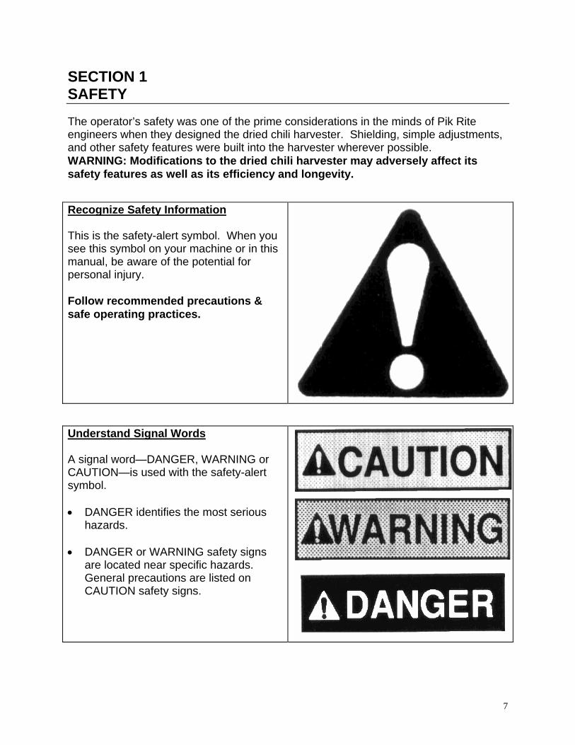
SECTION 1 SAFETY The operator’s safety was one of the prime considerations in the minds of Pik Rite engineers when they designed the dried chili harvester. Shielding, simple adjustments, and other safety features were built into the harvester wherever possible. WARNING: Modifications to the dried chili harvester may adversely affect its safety features as well as its efficiency and longevity. Recognize Safety Information This is the safety-alert symbol. When you see this symbol on your machine or in this manual, be aware of the potential for personal injury. Follow recommended precautions & safe operating practices.
Understand Signal Words A signal word—DANGER, WARNING or CAUTION—is used with the safety-alert symbol. • DANGER identifies the most serious
hazards. • DANGER or WARNING safety signs
are located near specific hazards. General precautions are listed on CAUTION safety signs.
7
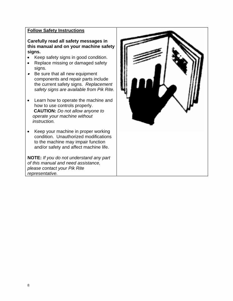
Follow Safety Instructions Carefully read all safety messages in this manual and on your machine safety signs. • Keep safety signs in good condition. • Replace missing or damaged safety
signs. • Be sure that all new equipment
components and repair parts include the current safety signs. Replacement safety signs are available from Pik Rite.
• Learn how to operate the machine and
how to use controls properly. CAUTION: Do not allow anyone to
operate your machine without instruction.
• Keep your machine in proper working
condition. Unauthorized modifications to the machine may impair function and/or safety and affect machine life.
NOTE: If you do not understand any part of this manual and need assistance, please contact your Pik Rite representative.
8

Operate Chili Harvester Safely All machinery must be operated by responsible persons who have been properly instructed and delegated to do so. • Do not stand or work under discharge
conveyor or header while harvester is operating.
• Do not stand between harvester and tongue while positioning tongue.
WARNING: The harvester may move
suddenly or fall while detaching. Use blocks under the wheels and release all stored energy from pickup float system before detaching harvesting unit.
• Do not put hands or feet between
tongue and frame opening while positioning tongue.
• Always operate machine at rated PTO speed.
WARNING: To avoid injury or death, disengage drives, shut off engine,
and make sure electrical power off before servicing or unplugging the harvester. The chains can feed dried chili plants faster than you can release your grip on the plants.
• Do not use your hands or feet to feed
plants into the harvester. • Do not stand between dried chili
harvester and tongue when detaching harvester.
WARNING: This dried chili harvester is intended for mobile field operation only. Never use machine in a stationary position or modify it to be used in one.
9

Keep Riders Off Machine and Tractor • Allow only the operator on the tractor
and only the laborers in the places designed for them. Keep riders off.
CAUTION: Workstations are built on
the Pik Rite Dried chili Harvester to ensure that laborers can safely stand while doing grading.
• Riders on machine are subject to
injury such as being struck by foreign objects and being thrown off of the machine.
• Riders also obstruct the operator's view resulting in the machine being operated in an unsafe manner.
Prepare for Emergencies Be prepared if a fire starts. • Keep a first aid kit and fire extinguisher
handy. • Keep emergency numbers for the
ambulance service, hospital, fire department, and doctors near your telephone.
10

Wear Protective Clothing • Wear close fitting clothing and safety
equipment appropriate to the job.
CAUTION: Do not wear radio or music headphones while operating machine. Operating equipment safely requires the full attention of the operator.
Protect Against Noise WARNING: Prolonged exposure to loud noise can cause impairment or loss of hearing. • Wear a suitable hearing protective
device such as earmuffs or earplugs to protect against objectionable or uncomfortable loud noises.
11

Handle Chemical Products Safely WARNING: Direct exposure to hazardous chemicals can cause serious injury. Potentially hazardous chemicals used with Pik Rite equipment include lubricants and paints. • A Material Safety Data Sheet (MSDS)
provides specific details on chemical products: physical and health hazards, safety procedures, and emergency response techniques.
• Check the MSDS before you start any
job using a hazardous chemical. That way you will know exactly what the risks are and how to do the job safely. Then follow the advised procedures and make use of the recommended equipment.
NOTE: Contact the Pik Rite Lewisburg,
PA office for MSDS sheets on chemical products used with Pik Rite equipment.
Stay Clear of Rotating Drive lines WARNING: Entanglement in rotating driveline can cause serious injury or death. • Keep the tractor master shield and
drive line shields in place at all times. Make certain that rotating shields turn freely.
• Wear close fitting clothing. Stop the
engine and be sure that the PTO driveline is stopped before making adjustments, connections, or cleaning out the PTO-driven equipment.
12

Use Safety Lights & Devices WARNING: Slow moving tractors and towed implements are difficult to see, especially at night, and may create a hazard when driven on public roads. Avoid personal injury or death resulting from collision with a vehicle. • Use flashing warning lights and turn-
signals when driving on public roads. • To increase visibility, use the lights
provided with your machine. Use a Safety Chain A safety chain will help control drawn equipment if it accidentally separates from the drawbar. • Attach the chain to the harvester main
frame and the tractor drawbar support or another specified anchor location. Provide only enough slack in the chain to permit turning.
• Use a chain with a strength rating
equal to or greater than the gross weight of the harvester (approximately 20,000 lbs.).
CAUTION: Do not use the safety chain for towing.
13

Reduce Speed When Towing Loads DANGER: Braking to stop towed loads from transport speeds can cause the towed load to swerve and upset. Reduce speed if towed load weighs more than the tractor and/or the tractor is not equipped with brakes. Follow recommended speed-weight ratio guidelines: • Maximum speed is 20 mph (32 km/h)
when towing a load equal to or less in weight than the tractor.
• Reduce speed to 10 mph (16 km/h)
when towing a load up to double the tractor weight.
• Do not tow loads exceeding double the
tractor weight. • Use additional caution when towing
loads under adverse surface conditions, when turning, and on inclines.
14

Practice Safe Maintenance Understand service procedure before doing work. Maintain cleanliness and dryness in work area. • Never lubricate or service the machine
while it is in motion.
WARNING: Be sure to keep hands, feet, and clothing away from power-driven parts. 1. Disengage all power and manipulate
controls to relieve pressure. 2. Lower equipment to the ground. 3. Stop the engine. 4. Remove the key. 5. Allow machine to cool.
• Securely support any machine
elements that must be raised for service work.
• Keep all parts in good condition and
properly installed. Fix damage immediately. Replace worn or broken parts. Remove any buildup of grease, oil, or debris.
• Disconnect battery ground cable (-)
and unplug main power supply cord on sorter before making adjustments on electrical systems or welding on machine.
15

Remove Paint Before Welding or Heating WARNING: Avoid potentially toxic fumes and dust. Hazardous fumes can be generated when paint is heated by welding, soldering or using a torch. • Do all work outside or in a well-
ventilated area. Dispose of paint and solvent properly.
• Remove paint before welding or
heating. • If you sand or grind paint, avoid
breathing the dust. Wear an approved respirator.
• If you use solvent or paint stripper,
remove stripper with soap and water before welding.
• Remove solvent or paint stripper
containers and other flammable material from the area.
• Allow fumes to disperse at least 15
minutes before welding or heating. Avoid Heating Near Pressurized Fluid Lines WARNING: heating near pressurized fluid lines, resulting in severe burns to you and bystanders, can generate flammable spray. • Do not heat by welding, soldering, or
using a torch near pressurized fluid lines or other flammable materials. Pressurized lines can be accidentally cut when heat goes beyond the immediate flame area.
16

Avoid High-Pressure Fluids WARNING: Fluid escaping under pressure carries the potential to penetrate the skin resulting in serious injury. • Avoid this hazard by relieving pressure
before disconnecting hydraulic or other lines. Tighten all connections before applying pressure.
• Search for leaks with a piece of
cardboard. • Protect hands and body from high-
pressure fluids. • If an accident occurs, see a doctor
immediately. WARNING: Any fluid injected into the skin must be surgically removed within a few hours or complications may result. Doctors unfamiliar with this type of injury should reference a knowledgeable medical source.
17
SECTION 2 PREPARATION, OPERATION & MAINTENANCE
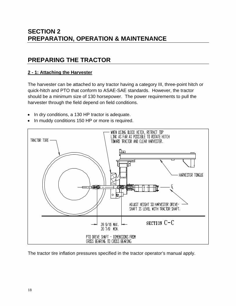
PREPARING THE TRACTOR 2 - 1: Attaching the Harvester The harvester can be attached to any tractor having a category III, three-point hitch or quick-hitch and PTO that conform to ASAE-SAE standards. However, the tractor should be a minimum size of 130 horsepower. The power requirements to pull the harvester through the field depend on field conditions. • In dry conditions, a 130 HP tractor is adequate. • In muddy conditions 150 HP or more is required. The tractor tire inflation pressures specified in the tractor operator’s manual apply.
18

2 - 2: Power Take-Off Shaft The tractor must have a PTO speed of 1000 RPM to match the power shaft speed of the harvester. The harvester can operate between 750 RPM (min.) and 1000 RPM (max.). Optimum speed is 850 RPM. That generally means operating the tractor engine at 1750 - 2200 RPM. [Note: This is assuming that pumps, motors, and other components are NOT excessively worn (after hours of use) and are operating correctly.] PTO energy consumption is at approx. 75 HP at 1000 RPM. A130 HP tractor is the minimum required. Pik Rite uses a 20 spline, 1-3/4 inch diameter PTO yoke. The 1-3/8 - 21 spline PTO shaft can be special ordered. 1. Before attaching the PTO to the tractor, be sure that the shaft is greased & can slide
freely in the tube. 2. Attach the PTO to the tractor. 3. Be sure that the PTO lock pin or latches are securely locked into the tractor's PTO
shaft. 2 - 3: Hydraulic Power The Pik Rite harvester relies on the tractor hydraulics to control the machine cylinder functions. A valve body located on the machine is equipped with an in-and-out hose that must be connected to the hydraulic outlets at the rear of the tractor.
19

In order to make the harvester compatible with any brand of tractor*, Pik Rite designs the harvester for operation in the continuous flow mode or closed center flow mode. This allows the farmer to use any brand of tractor*. The Pik Rite Dried Chili Harvester requires a... • Minimum of 8 gallons per minute & 1800 PSI • Maximum of 12 gallons per minute & 3000 PSI • The back pressure of the return line should not exceed 200 PSI Follow the tractor manufacturer's instructions for: CONNECTING AN ORBITAL HYDRAULIC MOTOR Connecting a hydraulic motor is identical to connecting the hydraulics to the Pik Rite Dried Chili Harvester. As of 1995, a pilot-operated check valve body is used. A higher or larger valve body identifies this. NOTE: These valves are recommended to be operated in the open center mode. NOTE: Reference your tractor manuals or dealers for more information. If you experience problems with your hydraulic system, contact Pik Rite for other options. *NOTE: Always check with your tractor dealer before connecting your hydraulics. In a few rare exceptions, some manufacturers use a special system for a term. Generally, these odd systems are identified within a segment of serial numbers, and kits are available for these tractors.
20

2 - 4: Electrical Power The Pik Rite Harvester relies on the tractor’s electrical system. At the minimum, an 80-amp alternator is required to keep the voltage constant during nighttime operations. Operating during the day without the lights requires less amperage. One hook up to the Auxiliary power supply (7 pin plug) is all that is necessary to operate lights, electro hydraulics and conveyor shut-off switches.
PREPARING THE HARVESTER 3 -1: Unpacking the harvester 1. Secure discharge conveyor cylinder bracket to the harvester main frame, using six 5/8” bolts. See Illustration A.
2. Remove the ½" bolt securing the transport bar to the sorting table post. Remove
the transport bar from the discharge conveyor. See Illustration B.
21

3. Extend the discharge conveyor main cylinder (this will lift the discharge conveyor
from stored position to upright position). See Illustration C.
22
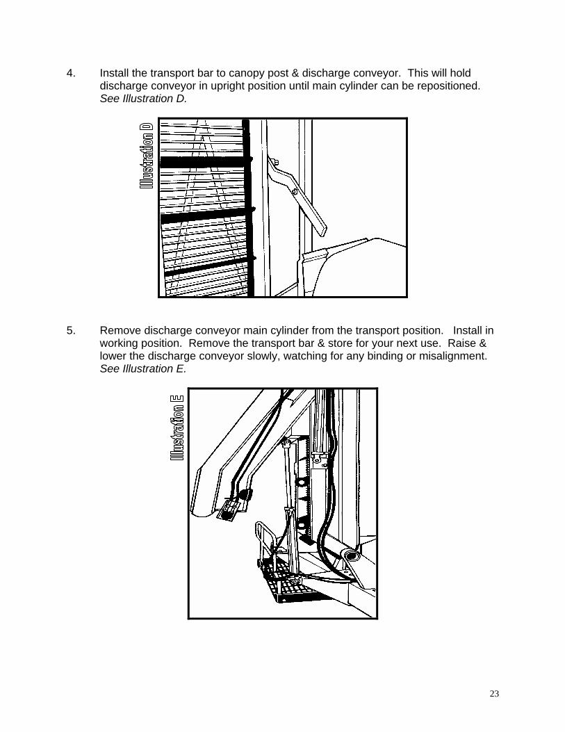
4. Install the transport bar to canopy post & discharge conveyor. This will hold discharge conveyor in upright position until main cylinder can be repositioned. See Illustration D.
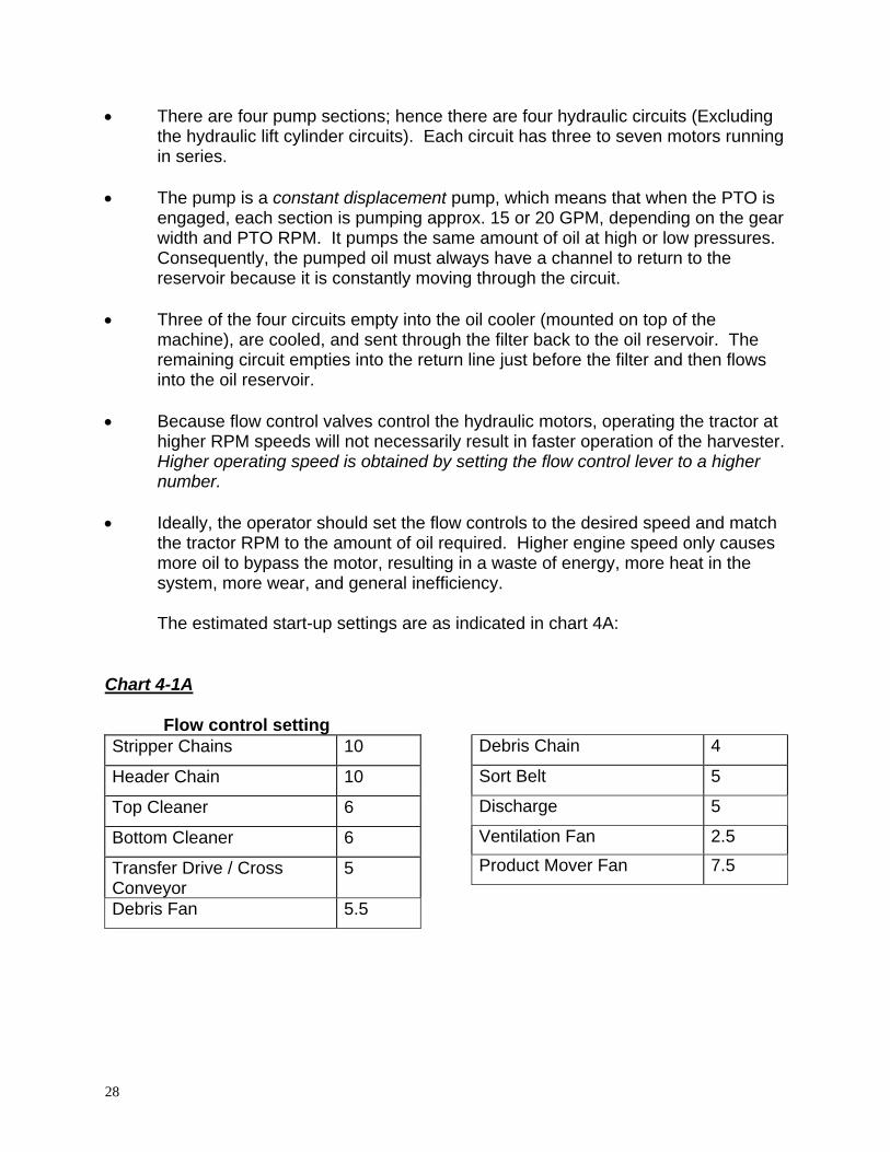
5. Remove discharge conveyor main cylinder from the transport position. Install in
working position. Remove the transport bar & store for your next use. Raise & lower the discharge conveyor slowly, watching for any binding or misalignment. See Illustration E.
23

6. Install the basket shields. Be sure the basket shields do not catch on the conveyor frame when moving the conveyor up & down, check to be sure that the conveyor belt will run smooth. See Illustrations F and G.
CAUTION: The basket shield and rear dried chili saver shield must be installed after the hand-sort conveyor is folded down.
7. Fold down the drive end of the hand sort conveyor. See Illustration H.
24

8. The belt tension at the rear of this conveyor may require readjustment. See Illustration I.
9. Install last basket shield. See Illustration J.
10. Pull out the decking & secure with the catches. See Illustration K.
25

11. Fold out the sun canopy. 3 - 2: Oil Levels 1. Be sure the main hydraulic reservoir is above the low line on the level /
temperature indicator located at the front of the reservoir. 2. Turn all of the flow controls to the 0 or off position. There are 10 to 15 controls,
depending on how the machine is equipped. 3 - 3: Final Preparations 1. Start the PTO at low RPM.
CAUTION: Always have a tractor operator on the seat and prepared to disengage the PTO when making the following observations and flow control adjustments.
2. Check for oil leaks in the event that a hydraulic fitting is loose or broken. 3. Check to be sure that the oil cooler fan located on the top of the machine is
turning counterclockwise therefore blowing air upward. 4. One by one, open each flow control to the #1 position and observe how it
functions. Be sure the component runs freely and without misalignment. 5. Slowly increase the speed to the desired setting. Later, while in actual field
conditions, fine adjust to meet requirements.
26

OPERATING THE HARVESTER CAUTION: Operating the Pik Rite Harvester requires much attention to detail. The operator must remain attentive to avoid injury to the crew or damage to the machine!
DANGER: To preserve life and limbs of crew cleaning the machine, the tractor operator must always warn them before engaging the PTO. • This warning needs to be understood by all crewmembers. • The harvester comes equipped with an Alarm on the harvester and in the
operator’s Control Box (in the tractor). • Operators should sound the Alarm or a signal from the tractor when
ready to start and then wait for an “all clear” response from the crew before engaging the PTO.
Crew members working on the harvester should sound the Alarm by pulling on Alarm Cord, located directly above the sorting area, to inform the operator and/or other crew member of Danger
4 - 1: Starting Speed Settings Speeds of conveyors and components will vary a great deal with field conditions. There is no prescribed speed at which to set the flow controls. However, there is an approximate start-up setting, and the operator needs to adjust as needed for conditions.
CAUTION: Never leave the machine running while getting off the tractor and adjusting the speed setting. Unless a technician on the machine is prepared to make the adjustment while running, always stop the PTO while making adjustments.
The Pik Rite Harvester may be operated at a maximum speed of 1000 PTO RPM or a minimum of 750 (Ideal field & harvester conditions) PTO RPM.
CAUTION: Idle the tractor down to engage and disengage the PTO. If the PTO is engaged or disengaged at high RPM, the pressure spikes may cause unnecessary wear to the hydraulic pump.
Speed control valves control all of the hydraulic motors except the cooling fan motor. These valves control speed by monitoring the amount of oil that is allowed to pass through the motor. The unused oil is passed around the motor. Both the bypassed oil and the oil that has passed through the motor flow together down line to the next flow control valve, where the process is repeated.
27
• There are four pump sections; hence there are four hydraulic circuits (Excluding the hydraulic lift cylinder circuits). Each circuit has three to seven motors running in series.
• The pump is a constant displacement pump, which means that when the PTO is
engaged, each section is pumping approx. 15 or 20 GPM, depending on the gear width and PTO RPM. It pumps the same amount of oil at high or low pressures. Consequently, the pumped oil must always have a channel to return to the reservoir because it is constantly moving through the circuit.
• Three of the four circuits empty into the oil cooler (mounted on top of the
machine), are cooled, and sent through the filter back to the oil reservoir. The remaining circuit empties into the return line just before the filter and then flows into the oil reservoir.
• Because flow control valves control the hydraulic motors, operating the tractor at
higher RPM speeds will not necessarily result in faster operation of the harvester. Higher operating speed is obtained by setting the flow control lever to a higher number.
• Ideally, the operator should set the flow controls to the desired speed and match
the tractor RPM to the amount of oil required. Higher engine speed only causes more oil to bypass the motor, resulting in a waste of energy, more heat in the system, more wear, and general inefficiency.
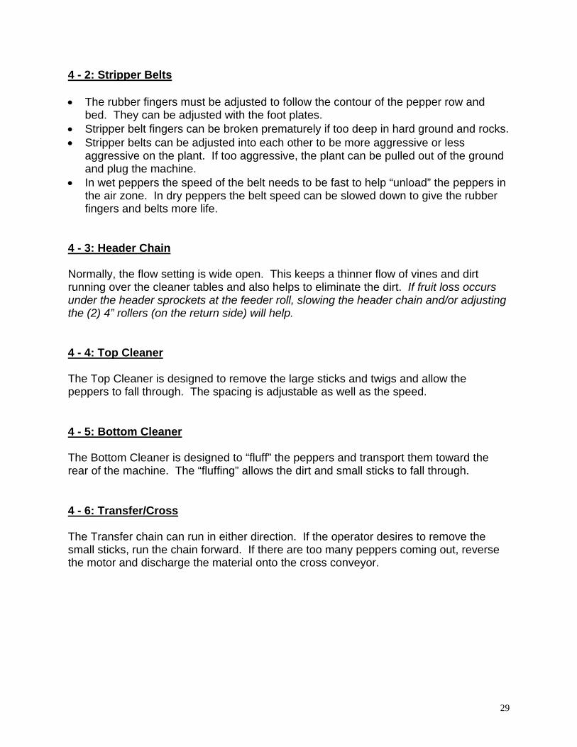
The estimated start-up settings are as indicated in chart 4A: Chart 4-1A Flow control setting Stripper Chains 10
Header Chain 10
Top Cleaner 6
Bottom Cleaner 6
Transfer Drive / Cross Conveyor
5
Debris Fan 5.5
Debris Chain 4
Sort Belt 5
Discharge 5
Ventilation Fan 2.5
Product Mover Fan 7.5
28
4 - 2: Stripper Belts • The rubber fingers must be adjusted to follow the contour of the pepper row and
bed. They can be adjusted with the foot plates. • Stripper belt fingers can be broken prematurely if too deep in hard ground and rocks. • Stripper belts can be adjusted into each other to be more aggressive or less
aggressive on the plant. If too aggressive, the plant can be pulled out of the ground and plug the machine.
• In wet peppers the speed of the belt needs to be fast to help “unload” the peppers in the air zone. In dry peppers the belt speed can be slowed down to give the rubber fingers and belts more life.
4 - 3: Header Chain Normally, the flow setting is wide open. This keeps a thinner flow of vines and dirt running over the cleaner tables and also helps to eliminate the dirt. If fruit loss occurs under the header sprockets at the feeder roll, slowing the header chain and/or adjusting the (2) 4” rollers (on the return side) will help. 4 - 4: Top Cleaner The Top Cleaner is designed to remove the large sticks and twigs and allow the peppers to fall through. The spacing is adjustable as well as the speed. 4 - 5: Bottom Cleaner The Bottom Cleaner is designed to “fluff” the peppers and transport them toward the rear of the machine. The “fluffing” allows the dirt and small sticks to fall through. 4 - 6: Transfer/Cross The Transfer chain can run in either direction. If the operator desires to remove the small sticks, run the chain forward. If there are too many peppers coming out, reverse the motor and discharge the material onto the cross conveyor.
29

4 - 7: Debris Fan
CAUTION: It is possible to over-speed the debris fan when operating high tractor PTO RPM.
• Operate the debris fan at a speed that satisfactorily removes the vines and debris. Do not over-speed or damage may occur.
• The operator can see from the tractor seat if all is well with the debris removal system and should regularly observe it as he travels down the row.
4 - 8: Hand Sort Belt Operate the hand sort belt fast enough to keep the peppers from stacking. The operator should determine belt speed-- he can see the entire machine and may need to speed up when the fruit flow is heavy. CAUTION: Because of motion sickness, etc., excessive belt speed may cause illness among some sorters. 4 - 9: Discharge Conveyor The discharge conveyor consists of three parts: the outer link, the lower link (adjusted up and down with a hydraulic cylinder) and the basket (the bottom part where the peppers drop into, from the hand sort belt). When the pepper flow is heavy, the lower link should be as close to the truck or as low as possible to prevent fruit from rolling back and bouncing over the side. The basket can be used to retain peppers until a truck can be positioned under the conveyor. NOTE: By turning the discharge conveyor off, the operator can save time because he doesn't need to empty the machine at the end of each row; instead, he can begin harvesting the next row while the truck is being positioned properly. CAUTION: The operator must pay close attention to the truck being pulled alongside the harvester. The discharge conveyor can be bent and rendered useless in a very short time if it is left unattended. 4 - 10: Ventilation fan This fan can be over sped, causing above normal pressurization of the Hydraulic System, and causing the air filters to plug prematurely. Only enough air to pressurize the enclosure is needed. Be sure to plug all the cracks and holes in the enclosure and unused debris chutes to keep this system efficient.
30

4 - 11: Cross & Debris Fan The Cross Conveyor speed controls the trajectory of the product falling onto the sorting table. The conveyor has an adjustable gap between the cross conveyor and the sorting table. This concept is to allow the heavy rocks and dirt clods to fall to the ground and the peppers to land on the sorting table. The Debris Fan is instrumental in assisting the pepper trajectory over the dirt gap, while the heavier material falls onto the ground. 4 - 12: Hydraulic System The operator should periodically observe the normal running pressures of the hydraulic pumps as he moves down the row. A high-pitched squeal (Flow Control with Relief) or hissing sound indicates that a relief valve in the hydraulic system is opening because a conveyor or other component has stalled out. By installing a pressure gauge at the hydraulic pump and using the process of elimination, the operator can identify the problem component. When a jam-up occurs, the motors require more power and thus the pressure gauge registers more pressure. To avoid problems: • Keep oil cooler fans clean. Check weekly. • Maintain hydraulic oil temperature at 150-160 degrees. • Keep hydraulic oil level within 10" of top of reservoir. • Change hydraulic oil filters each season. Check for water in oil by removing
magnetic plug at bottom of reservoir. Also check for metal fragments. Test Kits are available from your Pik Rite Dealer.
31

MAINTAINING THE HARVESTER
Preventative maintenance is better than emergency repairs.
5 - 1: Stripper Chains & Gathering Chains The outside chains for 36”-40” row centers are 64 bars long (60 Bars for 30”-35”). The inside chains for 36”-40” row centers are 62 bars long (58 bars for 30”-35”). • Keep the belt tension just tight enough to run smoothly--free and straight. • Check daily to be sure all belted chain rollers are turning. • Check daily the wear of the connecting clips and the condition of the rubber coated bars (Replace as needed). CAUTION: Over-tensioning will wear all components prematurely. 5 - 2: Product Mover Fan • Keep fan housing clean and free of debris by pressure washing weekly. • Grease 3 bearings weekly. 5 - 3: Header • Clean out build-up at pinch points, and keep header tunnel free of debris. • Check bolts on clip splices of header conveyor and gathering chains. These bolts,
when dragged through the dirt and rocks, sometimes wear off prematurely. • Lube roller chains daily (A quality roller chain oil is recommended). • Grease bearings once a week. You will find two grease fittings on the bearings of
the drive shaft. • Keep the belt tension just tight enough to running smoothly—free and straight. CAUTION: Over-tensioning will wear all components prematurely. • Keep grass and vines from wrapping on drive sprockets and clean the build up at
the pinch points. Grass and vines that wrap around the shafts at the bearings will damage the bearing seal and cause the bearings to fail.
32

5 - 4: Cleaner Tables The shaft centers are set 9” apart from factory for the top cleaner table. The shaft centers for the bottom cleaner table are set 5 ½” apart from factory. They may need adjusted depending on field conditions or varieties. • Check daily for debris wrapped around shaft and prematurely wearing bearing
seals. • Lube roller chains daily and make sure they are tight. 5 - 4A: Cleaner Table Deflector Chain Use spacer blocks to move chain higher or lower in adjusting slots. • Check chain daily to make sure it is running freely and straight. • Check regularly for missing bolts in clip splice and condition of connecting rod and clips. 5 - 5: Transfer Chain • Check daily that the chain is running freely and straight, with hold up rollers in place. • Keep chain free of debris and drive shaft free from wrapping debris. • Check regularly for missing bolts in clip splice and condition of connecting rod and clips. 5 - 6: Cross Conveyor • Check daily that the belt is running straight and has proper tension. • Clean belt as needed. 5 - 7: Debris Fan • Check daily for dirt, rocks and debris in side of fan housing and at bottom. • Daily clean the dirt build-up off of the top deflector hood. • Pressure wash weekly for peak efficiency.
33

5 - 8: Debris Chain and Debris Roller • Check daily that chain is running freely and straight, and that finger roller is rotating and cleaning debris fan properly. • Check regularly for missing bolts in clip splice and condition of connecting rod and clips. 5 - 9: Hand Sort Belt The hand sort belt …. • Adjust the tail and drive pulleys to run the belt in the center of the bed. Running
slightly to one side is acceptable, provided it isn't wearing into the slider bed sides. • Clean out the tail pulley daily. 5 - 10: Discharge Conveyor The discharge conveyor … • Check the lap splice belts daily. • Keep the belt running freely between the rollers. • Check the basket sides. • Check that the tunnel is free of debris, and not creating pinch points. NOTE: The discharge conveyor is designed so that it does not damage other components. If an operator accidentally bends the conveyor, it can be straightened out rather easily: simply pull it in the opposite direction that it was bent. 5 - 11: Electro-Hydraulic Valve & Control The electro-hydraulic valve is located at the front of the machine. A standard machine consists of 7 portions. Starting from the top, they include the following: U - Unload with inlet & outlet ports #1 – Gauge Wheel (inside) #5 - Sliding Hitch
#2 – Gauge Wheel (outside) #6 – Header (outside) #3 – Discharge (outer) #7 - Header (inside) #4 – Discharge (main) • For open center, the coil and cartridge should be installed in the unload section with
the appropriate wire attached to the coil.
34

• A check valve in the inlet line permits the oil to flow through the valve in the correct direction. If the oil is flowing in the wrong direction, the valve will not work. A high- pressure filter in the inlet line removes dirt coming from the tractor. If the filter becomes clogged and oil bypasses the filter, a bypass (signified by a red pin on the top of the filter) pops up.
• In an open center application, tractor hydraulic oil is free flowing through the harvester valve body. When the electric switch is activated, an electric coil opens the spool to send oil to the hydraulic cylinder. However, the oil is still flowing freely. Consequently, the unload coil must be employed at the same time to temporarily stop the free-flowing oil in order to build up the pressure needed to move the cylinder. The unload coil, therefore, is activated and deactivated simultaneously with the electric switch. (There are electrical diodes in the control box preventing electrical feedback through to other inactivated functions).
NOTE: In order to make the harvester compatible with any brand of tractor*, Pik Rite designs the harvester for operation in the continuous flow mode. This allows the farmer to use any brand of tractor* without the complications of changing the harvester valve body when switching tractors. The Pik Rite Dried chili Harvester requires the following: CAUTION: The backpressure of the return line should not exceed 200 PSI Cylinder Speed Adjustment: To adjust cylinder speed, follow these steps:
Stackable Section Valve
1. Loosen locking nut (shown above). 2. To decrease cylinder speed: Turn adjuster screw (shown above) clockwise until
desired speed is achieved. 3. To increase cylinder speed: Turn adjuster screw counterclockwise until desired
speed is achieved.
35

5 - 12: Lubrication and Oils 1. Hydraulic Oil and Maintenance Oil Specification NOTE: Viscosity and cleanliness are the most important items to consider in maintaining long life in the hydraulic system. • Pik Rite recommends *Hydrocarbon-based oils that will maintain a viscosity of 80-
100 SUS (15-20CST) at operating temperatures. • Start-up viscosity must not exceed 7500 SUS (1600 CST) and also must maintain
*ISO cleanliness levels of 19/17/14 or better. 1. Viscosity Requirements Definitions: • Viscosity is the measure of how a fluid resists flow. • Operating temperature viscosity is the temperature at which oil does its work. When viscosity increases fluid becomes thicker, conversely as the temperature increases fluid becomes thinner. This may cause problems. CAUTION: A viscosity must be selected that will flow freely and yet be thick enough to lubricate the moving parts in the pump and motors. • Pik Rite Harvesters are shipped with ISO grade 46 with viscosity index of a minimum
of 90. Additives need to include rust and oxidation inhibitors and foam depressant. This is good grade oil for average daytime temperatures at harvest time.
• Any good quality ISO grade 46 oil or SAE 10 motor oil is acceptable, providing that
the viscosity is within specification at operating temperatures and start-up temperature.
• If average daytime temperatures are above 95 degrees F and the machine's
hydraulic oil temperature rises to 180 degrees F, Grade #46 viscosity may be too low. If this oil is too thin (viscosity too low), oil with ISO grade of 68 or SAE 15 may need to be installed.
• Mixing thicker oil (higher viscosity), such as SAE 30 or ISO 100, is a means of
increasing the operating viscosity. After this is done, an oil sample should be sent to a lab for testing to insure proper viscosity.
NOTE #1: ISO standards allow up to 10% variation from a specification. An ISO grade 46 hydraulic oil can actually be 42 or 50 and be considered a grade 46.
36

NOTE #2: When using motor oils, non-detergent is preferred; however, detergent oil is not harmful. The detergents will tend to hold or suspend any moisture in the oil. Many hydraulic oils include in the additives an emulsifier, which will encourage the water to separate and be drained off the bottom of the reservoir.
2. Cleanliness Requirements • The components on the harvester must have an *ISO cleanliness level of 19/17/14.
This means that there must be fewer than 150 parts per milliliter in the 5-micron or greater size and fewer than 200 parts per milliliter in the 15-micron or greater size. (A human hair is about 70 microns in diameter and talcum powder is 10 microns.)
• Filters must maintain this level of cleanliness. Any filter may be used providing that
the above results are achieved. The hydraulic oil must be "clear" and not "milky". A "milky" looking oil is a good indication that excessive water is present.
• To determine cleanliness level, send oil samples to a lab for analysis (a common
procedure). *International Standards Organization The most accepted fluid system contamination level designation in use today is the ISO "Solid Contamination Code" (ISO #4406). This format plots cleanliness levels (ISO Codes) based on particle counts at 5 and 15 micrometers per 100 ml of fluid under evaluation. An additional count at 2 microns is under review by ISO and likely to be adopted soon. Pik Rite has accepted this as a standard as of 4/15/95. *Hydrocarbon based Hydrocarbon- (petroleum) based hydraulic fluids and straight oils are the most common fluids for hydraulic systems. The difference between a hydrocarbon-based hydraulic fluid and straight oil is generally the additive. Some automotive or crankcase motor oils with the proper additives can be acceptable. 5 - 13: Hydraulic Pump The Hydraulic system can be diagnosed and analyzed with some basic information. A phone call to a service man with this information may prevent breakdowns or permanent damage to the machine. A. Analyzing Hydraulic Pump Pressures NOTE: Hydraulic pump pressures should be analyzed at operating temperature. Observe and record the following: 1. Approximate outside temperature at time of tests ________ 2. Approximate operating PTO RPM ________ 3. Operator’s customary engine speed when engaging the PTO ________
37

4. Machine’s hydraulic oil temperature ________ 5. Return filter pressure (located on filter base) ________ 6. Machine’s hydraulic pressures while running in the field ________ 7. Stall-out pressures of each pump section (relief valve setting) ________ Observe and record the following: Section #1: Port closest to tractor on bottom side of pump: Average Pressure____ Highest Pressure____ Stall out Pressure____ Section #2: Port closest to the tractor on the topside of pump: Average Pressure____ Highest Pressure____ Stall out Pressure____ Section #3: Port Located on the bottom-rear of pump: Average Pressure____ Highest Pressure____ Stall out Pressure____ Section #4: Port located top-rear of pump: Average Pressure____ Highest Pressure____ Stall out Pressure____ NOTE: Stall out pressures can be determined by stalling a motor in the section tested. • Use a pipe wrench on the motor coupler and start PTO at low RPM. • Observe the pressure, and record it. • Call or send this information to a Pik Rite service technician. This information will
help in determining the condition of the hydraulic system. B. Setting Pressures on Hydraulic Relief Valves • Oil temperature should be approximately 100º. • PTO speed should be approximately 950 RPM. Pump 1 (bottom front pump port), second from top relief valve:
A. Stall out a stripper chain motor then slowly start the PTO. Set relief to 2850 PSI at the pump test port.
Pump 2 (top front pump port), bottom relief valve:
A. Stall out the product mover fan motor then slowly start the PTO. Set pressure relief to 2400 PSI.
Pump 3 (bottom rear pump port), relief valve is mounted at bottom of aftersort flow control:
A. Stall out the aftersort motor by using a pipe wrench on the motor coupler, then
38

slowly start the PTO. Pressure should be 2400 PSI. Pump 4 (top rear pump port), second from top relief valve:
A. Stall cross conveyor motor by using a pipe wrench on the motor coupler, and then slowly start the PTO. Pressure should be 2400 PSI.
C. Analyzing Hydraulic Pump Flows Install a flow meter at the pump and record pump output (GPM) at different pressures; i.e. 1500 PSI, then 2500 PSI, etc., note the GPM’s at each pressure setting. NOTE: Pik Rite service personnel have flow meters. NOTE: Test should be performed with PTO at aprox. 900 RPM and oil temperature at 100 degrees or more and with flow controls wide open on the components being checked. 5 - 14: Checklist NOTE: Owner / operator may add to this list at his own discretion Daily
For all safety shields/decals in place, and harvester is in safe working condition including lights and horn
Grease all (10) hour grease points Tires All belted chain rollers for rotation, and excessive wear Bent belted chain rods Fins on oil cooler for cleanliness Filters on enclosure vent fan Flat conveyor belts for tension, alignment/wear (edges and v-guide) Roller chain sprockets set screws/ taper bushing secure, also assure key is in place Oil level and temperature in oil reservoir Assure all points such as belted chains etc are not rubbing side panels, shields or
other that could cause premature wear
Weekly
Grease all (50) hour grease points Lubricate roller chains (when chains are warm if possible) All tire pressures Wear on header return roller (adjust hold up rollers on belted chain to prevent wear)
39

Alignment of belted chain and sprockets within the conveyor Tension and wear of roller chains Center rocker bolts (center of big wheel rockers) (2) places Alignment of motor drive couplers (non solid/rigid)
Yearly
Inspect and lubricate all wheel bearings Recheck weekly and extended season list Replace hydraulic oil filters (2 oil tank, 1 breather for oil tank, 1 high pressure for
cylinder valve) hydraulic oil sample test kits are available if desired Check pressure and flow of the four pump sections Condition of belted chains Check all roller chain and belted chain sprockets rubbing, wearing, etc) Clean and paint any metal that has been rubbed or scuffed
Keep These Areas Clean
Front header chain area (cross pieces) Wheel and rocker area Debris fan intake (front and rear), paddles, and inside of hood Discharge basket area
Extended Season Maintenance / 300+ Hours or Adverse Conditions
Belted chain con rods, clips, bolts and rivets Wear on roller chain, and belted chain sprockets for wear Bar cleaner sprockets for wear All motor drive couplers Steel/rubber belted chain return rollers for wear Aftersort belt lacer and lacer pin for wear
End of Season Maintenance
Lubricate all rollers with moisture displacing lubricant or a good quality penetrating oil
40