DEAERATOR
32
DEAERATOR 1.0 Introduction: Modern Power Plants are operated at high pressures and temperatures and the presence of oxygen in dissolved form in feed water results in harmful corrosive attack. Of the many measures adopted to contain corrosion in boilers and associated plant, the removal of oxygen from feed water is the most important one. Incorporating a deaerating unit in the feed system does this removal of air or deaeration. 2.0 Functions Of The Deaerator: In addition to the primary function i.e., ‘Deaeration', the Deaerator also serves for the following purposes: 1. The Deaerator functions as a surge tank of feed water capable of meeting the variable demands of the plant 2. The Deaerator also forms a part of the regenerative heating system improving the temperature of condensate 3. It also acts as a heat-conserving unit. 3.0 Sources Of Oxygen Entry Into The System: 1. The DM water stored in the condensate storage tank is exposed to the atmosphere and hence the air gets dissolved in water. When this water is added at the condenser Hot well as make up water, oxygen makes entry into the systems. 2. The condenser itself is the source of air entry since it can not be made to work as a fully air tight vessel 4.0 Effect Of Oxygen In Feed Water: Most frequently encountered problem in any power station is electrochemical corrosion and it is intensified by the presence of dissolved oxygen in the feed water. It occurs when the metal of the heating surfaces is attacked by electrolytic solutions (i.e. feed water here) and hence the flow of current from one part of the metal to another through the electrolyte. Water, the electrolyte, contains equal numbers of positively charged hydrogen cations (H + ) and negatively charged hydroxyl anions (OH - ). Different areas of the same metal (e.g.: Iron) may themselves act as an anode or a cathode. The electrolyte (water) couples the anode and the cathode areas to form a galvanic cell. Due to the difference in potential between the two areas, the corrosion current flows between the anode and
-
Upload
agnihothri-agni -
Category
Documents
-
view
208 -
download
0
description
DEAERATOR
Transcript of DEAERATOR

DEAERATOR 1.0 Introduction:
Modern Power Plants are operated at high pressures and temperatures
and the presence of oxygen in dissolved form in feed water results in harmful
corrosive attack. Of the many measures adopted to contain corrosion in
boilers and associated plant, the removal of oxygen from feed water is the
most important one. Incorporating a deaerating unit in the feed system does
this removal of air or deaeration.
2.0 Functions Of The Deaerator: In addition to the primary function i.e., ‘Deaeration', the Deaerator also
serves for the following purposes:
1. The Deaerator functions as a surge tank of feed water capable of
meeting the variable demands of the plant
2. The Deaerator also forms a part of the regenerative heating system
improving the temperature of condensate
3. It also acts as a heat-conserving unit.
3.0 Sources Of Oxygen Entry Into The System: 1. The DM water stored in the condensate storage tank is exposed to the
atmosphere and hence the air gets dissolved in water. When this water
is added at the condenser Hot well as make up water, oxygen makes
entry into the systems.
2. The condenser itself is the source of air entry since it can not be made
to work as a fully air tight vessel
4.0 Effect Of Oxygen In Feed Water: Most frequently encountered problem in any power station is
electrochemical corrosion and it is intensified by the presence of dissolved
oxygen in the feed water. It occurs when the metal of the heating surfaces is
attacked by electrolytic solutions (i.e. feed water here) and hence the flow
of current from one part of the metal to another through the electrolyte.
Water, the electrolyte, contains equal numbers of positively charged
hydrogen cations (H+) and negatively charged hydroxyl anions (OH-).
Different areas of the same metal (e.g.: Iron) may themselves act as an
anode or a cathode. The electrolyte (water) couples the anode and the
cathode areas to form a galvanic cell. Due to the difference in potential
between the two areas, the corrosion current flows between the anode and

the cathode areas through the electrolyte (water). Deterioration (corrosion)
takes place where the current leaves the metal i.e., at the anode area. The
electrons (negative charges, i.e., e-) leave the anode and flow to the
cathode areas. Since these electrons are released by the metal (iron) atoms
at the anode surface, the metal atoms become a positively charged ion.
Fe ↔Fe ++ + 2e-
Ferrous ions formed at the anode area are attacked by negatively
charged hydroxyl ions (OH -) and tend to unite to form an unstable
compound called Ferrous hydroxide Fe (OH) 2
Fe ++ + 2OH - → Fe (OH) 2
Due to the presence of dissolved oxygen in the feed water, oxidation of
unstable ferrous hydroxide takes place resulting in the formation of Ferric
hydroxide (Common rust)
4Fe(OH) 2 + O2 +2H2O → 4Fe(OH) 3
Ferric hydroxide on heating in the boiler becomes ferric oxide i.e., rust.
4Fe(OH) 3 → 2Fe2O3 + 6H2O.
The electrons arriving at the cathode area neutralizes some of the
hydrogen cations (H+) collected there.
2H+ + 2e- → H2↑
Cathode area is subjected to only a protective reaction. Anode and
cathode processes occur simultaneously supporting each other. However,
the potential difference between the two areas is a necessary condition.
As the corrosion products build up at the anode and the cathode areas,
the voltage difference tends to dip slowing down the rate of corrosion. This
change is called ‘Polarisation’. The process which reduces Polarisation i.e.,
intensifies corrosion is called ‘Depolarization’. The substances those
contribute to depolarization are called as ‘Depolarisers’.
Oxygen dissolved in feed water acts as a depolariser. Hydrogen gas (H2)
formed after neutralization by the electrons can blanket the cathode surface
thereby reducing the rate of corrosion. Hydrogen blanket on the cathode
surface may be removed by combining it with oxygen as a depolarization
process.
4H+ + O2 + 4e- = 2H2O
Thus, the dissolved oxygen in the feed water promotes the corrosion on
the heating surface by

1. Helping in the process of oxidation and
2. Acting as a depolariser so as to intensify the process at corrosion.
Concentration of dissolved oxygen in the feed water for high-pressure
boilers should be maintained at less than 0.005 ppm.
5.0 Principle Of Deaeration: Deaeration is based on the following two principles:
1. The solubility of a gas in a definite mass of a liquid is inversely proportional
to the temperature of the liquid.
If water is heated up to its saturation temperature (boiling temperature)
and kept at this temperature for a sufficient period, the gases can be
removed and vented to atmosphere due to their reduced solubility. This
process of heating takes place in the LP heaters and inside the Deaerator
itself with an aim to reduce the solubility of the gases.
2. The mass of a gas, which a definite mass of a liquid will dissolve at a given
temperature, is directly proportional to the partial pressure of the gas in
contact with the liquid. This holds within close limits for any gas, which does
not unite chemically with the solvent.
The term, “the partial pressure of a gas “can be explained by studying
“Dalton’s Law of Partial Pressure”. If it is considered that there is a
homogeneous mixture of inert ideal gases at a temperature ‘T’, a pressure ‘P’
in a volume ‘V’, it follows that
P = P1 + P2 + _ _ _ _ _ Pn
Where P = the total pressure
P1, P2, _ _ _ Pn = Partial pressures of the gases concerned.
(Since there is no chemical reaction, the mixture is in a state of equilibrium).
“The partial pressure of a gas “is the pressure that the gas would exert if it
occupies the entire volume ‘V’, at the temperature ‘T’. Dalton’s Law of
partial pressure states that the total pressure of a mixture of ideal gases is
equal to the sum of the partial pressures exerted by the individual gases.
The solubility of oxygen (air) in feed water can be reduced by decreasing
the partial pressure of oxygen. Decreasing the partial pressure of oxygen in
contact with feed water may be achieved by any one of the following
methods.
1. Decreasing the total pressure
2. Using another gas (whose pressure is higher than the partial pressure of
gas dissolved) to scrub the liquid.
In the case of the Deaerator, the total pressure cannot be decreased, as
it will affect the other system parameters. Use of steam to remove the oxygen
in the feed water can be done. When steam is used for removing the oxygen
in the feed water, it preheats the feed water further. It also acts as a carrying
medium to take the liberated gases to the atmosphere.
Since the process of Deaeration is carried out along with heating, it is
called as ‘Thermal Deaeration”.
To increase the efficiency of heating and deaerating and to increase the
rate of Deaeration, ‘the area of contact’ and ‘the duration of contact’
between the steam and the feed water have to be sufficiently increased.
Hence, a water distribution system comprising of spray nozzles and
perforated trays is to be provided in addition to an efficient distribution
arrangement for steam inside the Deaerator.
6.0 Chemical Deaeration: In order to remove the traces of oxygen present in the feed water after
thermal Deaeration, chemical means is employed. Either sodium sulphite or
hydrazine hydrate can be used for oxygen removal. Hydrazine is found to
possess distinct advantages over sodium sulphite as a de-oxygenating
chemical.
1. Hydrazine is a powerful reducing agent and is effective in removing
even the last traces of oxygen in water
N2H4 + O2 2H20 + N2↑
2. Its decomposition and reaction products do not increase the solid
contents in the water. The reaction products are only nitrogen and
water.
3. Small quantity of hydrazine is required compared to the requirements
of sodium sulphite. (Removal of 1 ppm of oxygen requires 1 ppm of
Hydrazine/ 8 ppm of Sodium Sulphite)
4. Hydrazine and the decomposition products of the excess hydrazine
are not acidic. They help in maintaining an alkaline pH, which is good
for the power station operation.
5. It also removes other oxidizing impurities like Cl2.

6. Hydrazine also reacts with oxides of iron and copper and removes
them from the system. The black magnetic, oxide of iron viz.magnetite
(Fe3O4) obtained as the product of interaction between rust (Fe2O3)
and hydrazine forms a thin coating on the metal surface and provides
a protective layer preventing any further attack on the metal.
Hydrazine is dozed slightly in excess such that the trace of oxygen present
after thermal Deaeration is removed. The hydrazine dosed in excess remains
as hydrazine until the feed water temperature touches 270 °C. When the
feed water temperature goes beyond 270 °C, the hydrazine decomposes as
given below:
3N2H4 4NH3 + N2↑
The above reaction leads to the formation of Ammonia, which is alkaline
in nature.
If ammonia is present in excess in the feed water for prolonged periods, it
attacks non-ferrous metals like copper and its alloys. This can cause severe
corrosion in condenser and low-pressure heaters provided with the tubes
made of copper alloys. The ammonia concentration in the main condensate
water should never exceed 10 ppm.
Dosing of hydrazine is hence regulated such that the concentration of
ammonia in the main condensate water is between 0.2 to 0.5 ppm.
7.0 Description Of Deaerator The Deaerator of units IV to VII of Thermal Power Station – II / Stage –II is of
combined spray and tray type. It consists of two elements viz a feed water
storage tank and a deaerating header.
The feed water storage tank is a horizontal cylindrical vessel with dished
ends at either end. The horizontal deaerating header is connected at the
upper part of the feed water storage tank. The details shown in figure - (1)
7.1 Storage Tank: The feed water storage tank is fabricated from boiler quality steel plates.
There are three supports in the bottom of the storage tank. The central
support is a fixed one. The end supports are of sliding nature to
accommodate the thermal expansion of the storage tank. The end supports
are rollers supports with two rollers in each. Movement of roller support from
cold to hot condition is about 8 mm. The storage tank is provided with two


n
M
h
th
sa
D
p
d
p
p
p
d
h
e
p
7
st
umbers
Man- hole
While
eating c
he storag
aturation
Deaerato
preheatin
distributed
pipes. An
preheatin
The BF
provided
damage
as also o
etc., as d
provided
7.2 DThe d
torage ta
of safety
es are pro
the ma
cum the
ge tank.
n tempe
or. This i
ng steam
d along
other co
ng steam
FPs take
in the f
Boiler Fe
other con
detailed l
for the st
eaeratideaeratin
ank. It co
y relief v
ovided fo
ain cond
deaerat
Initially t
erature c
is done
m can be
the leng
onnection
line.
the sucti
feed wa
eed Pump
nnection
later. Pre
torage ta
ng Heang head
omprises
alves. Th
or interna
densate
ting stea
the feed
correspo
with th
e admitt
gth of th
n is also
ion from
ater outle
ps due to
ns for HPH
essure, Le
ank.
der: der is a
of a wa
he capac
al inspec
is led i
m entry
d water i
nding to
he help
ted at o
he tank t
provided
the bott
et pipe
o entry o
Hs drain c
evel and
steel sh
ater distri
city of th
ction of th
nto the
pipe is c
in the sto
o the o
of aux
one end
through
d with de
om of th
to preve
of steam
condens
d Temper
hell mou
butor wit
he storag
he storag
deaera
connecte
orage ta
perating
xiliary ste
of the s
many v
eaerating
he tank. A
ent vortic
bubbles
sate, BFP
rature ins
nted on
th spray
ge tank
ge tank.
ating hea
ed at on
ank is reh
g pressur
eam sys
storage
ertical p
g heade
A vortex
ces, whic
. The stor
recircula
strument
n the fee
nozzles a
is 130 m
ader, th
ne end o
heated t
re of th
stem. Th
tank an
perforate
r from th
breaker
ch woul
rage tan
ation line
s are als
ed wate
and tray
3.
e
of
o
e
his
d
d
his
is
d
nk
es
o
er
ys.

In order to increase the efficiency of deaeration, the area of contact and
also the duration of contact between the main condensate and deaerating
steam are increased by breaking the main condensate into fine particles (in
the form of spray) and also making the condensate flow down through
perforated trays.
The main condensate, which is pre-heated in 3 nos. of LPHs, is making its
entry into the Deaerator at the top of the deaerating header. Then the
condensate is sprayed with the help of 40 nos. of spray nozzles provided at
the distributor. (Ref. Fig: 1). The condensate is sprayed over 2 stacks of
perforated trays. Each stack has 5 nos. of trays in it. The duration of contact
gets increased as the water flows down through the trays. The deaerating
steam admitted at the storage tank rises up in a counter flow direction to the
main condensate flow. The process of deaeration takes place at the header.
Most of the steam quantity is recovered as feed water on condensation. The
remaining quantity of steam along with air removed leaves the deaerating
header through Deaerator vents. By this, the main condensate is also pre-
heated before it reaches the storage tank.
Tray removal doors are provided on both sides of the deaerating header
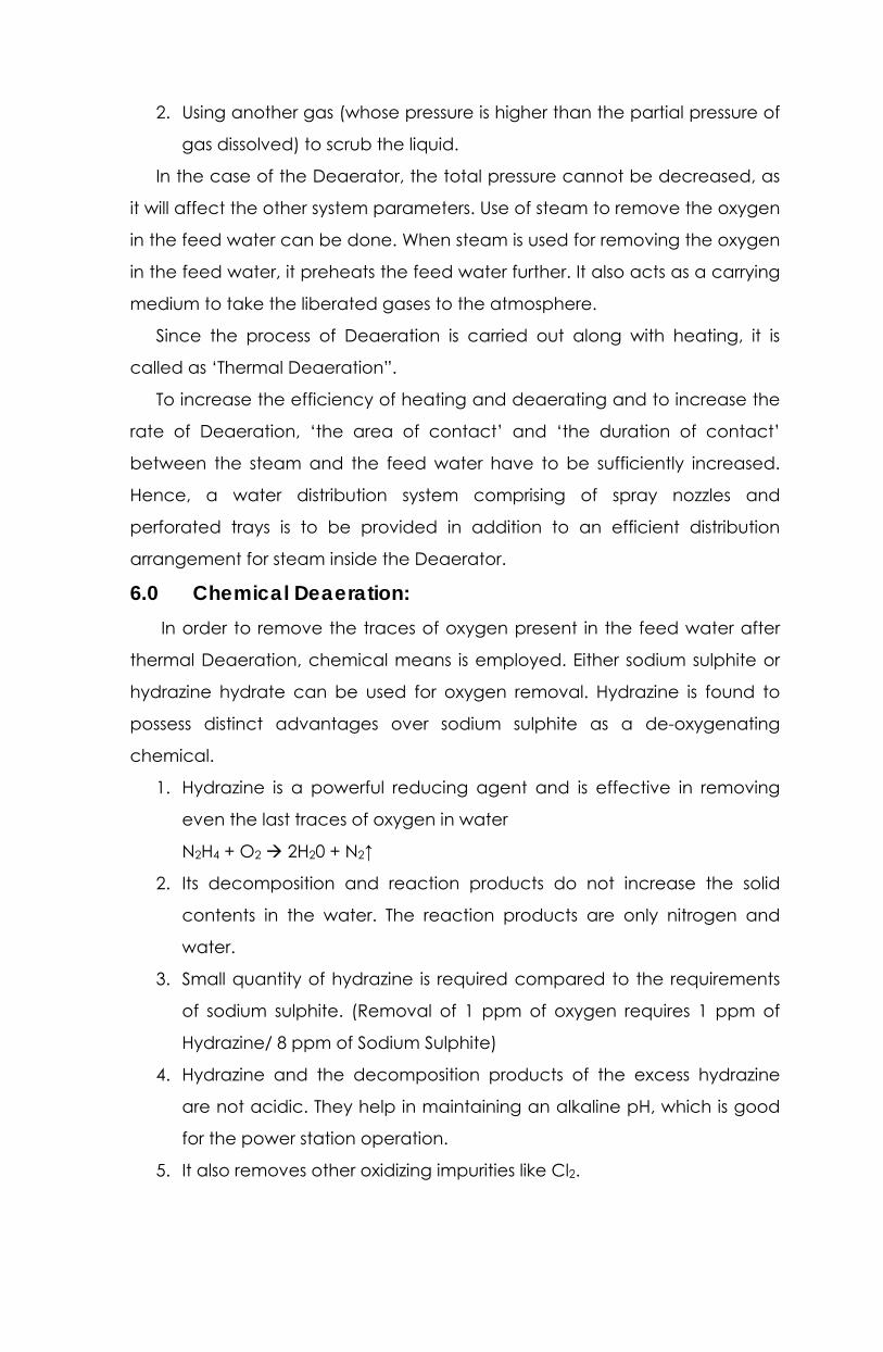
8.0 Deaerator Connections: (Ref. Fig: 2 and 3) The following inflow and outflow connections of steam and water
provided for the Deaerator.
8.1 Steam Inlets: 1. The deaerating steam for Deaerator enters at one end of the storage
tank from a common junction formed by the following 3 sources of steam.
a) Normal source of steam: The normal source of deaerating steam is
made available from the 4th Extraction steam of Turbine. It is tapped from IP
cylinder exhaust steam, is from cross around pipes, after 20 stages of IP
casing. It is admitted through an electric motor driven isolation valve EX-014.
b) 1ST standby source of steam (CRH Steam): In order to feed the
Deaerator during the occasions in which 4th extraction steam of Turbine is
not sufficient, a stand by source of steam is warranted. The steam drawn
from CRH lines is used as 1ST standby source of steam for the Deaerator. The
supply of CRH steam is made available through a pressure control station
comprising of an electric motor driven inlet isolation valve (EX-001), and a
pneumatic control valve (PCV-2) as shown in Fig: 2. The Deaerator can also


be fed from CRH lines during the occasions in which the Turbine is not in
service and the Boiler is in service with HP and LP bypass systems.
c) 2nd standby source of steam (Pegging/Auxiliary steam): In order to
feed the Deaerator during initial start-up periods and also during the period
after shut-down, where both 4th extraction steam and CRH steam may not
be sufficient, another source of steam is made available from Auxiliary steam
bus. This steam also admitted through a pressure control station PCV-1.
All the above 3 sources of steam are made available to the junction with
provision of NRVs in order to prevent any back flow. Four numbers of line
Safety valves are also provided to relieve the increase in pressure in case that
any pressure control valve malfunctions.
2) Preheating steam from the auxiliary steam system:
Initial preheating of feed water in the storage tank can be done with the
help of steam drawn from the auxiliary steam bus.
3) CBD (continuous Blow Down) tank steam to the storage tank:
Continuous blow-down from boiler drum is resorted to keep the salt
concentration of boiler water not only within limits i.e., not to cross the critical
value which will result in salt carry over along with steam but also to maintain
a steady salt concentration irrespective of time. This is achieved by making
the salt input to the cycle through the make up water supplied in the
condenser equal to the salt output from the cycle through the continuous
blow-down.
Since practically there is no salt carry over along with steam from the
boiler drum, all the salts remain trapped in the boiler drum water. This highly
salt concentrated water from the boiler drum is taken, thereby reducing
considerably the need of make up water.
The CBD water is at high pressure and temperature and consequently has
a high enthalpy. Roughly, one third of this water is flashed into steam in the
CBD flash tank located near the Deaerator. Pressure maintained in this tank is
slightly above that of the Deaerator. The CBD flashed steam is supplied to the
deaerator continuously. This is one of the sources of steam supply to the
deaerator.The quantity of water wasted is roughly two thirds of the water
taken from the boiler drum. This cannot be used as it is highly contaminated.
Further reduction in make –up water need is achieved by this.

Water from CBD flash tank goes to the intermittent blow-down flash tank
where further flashing takes place. Steam is let out to atmosphere and the
water to the drainage.
Thus, the CBD flash tank arrangement not only reduces the make up
water requirement to the cycle considerably but also results in the utilization
to the maximum possible extent of the heat energy of the CBD water.
The CBD flash tank steam is admitted to the storage tank through a gate
valve and a NRV.
4) Shell Vents of HPHs (5) & (6) (2 Nos.) to the Deaerator header:
Heat transfer between the extraction stream and the feed water takes
place in HP heater. Non-condensing gases coming along with the extraction
steam also enter the heaters. If they are allowed to remain, they get
accumulated in the heaters. These gases blanket the surface of the heater
coils and the performance of the heaters will get affected. If the oxygen is
also present in these non-condensing gases, it will promote corrosion of the
tubes since the stream is getting condensed there. Hence continues venting
of non- condensing gases is warranted. The shell vent of HP heaters (5) and
(6) are connected to the deaerating header for evacuating the non-
condensing gases along with a small part of the extraction steam. Thus, these
gases are finally driven out to atmosphere through the Deaerator vent. These
vent lines are provided with isolation valves and non return valves.
8.2 Water Inlets to Deaerator: 1. Main condensate after LP Heater (3):
The main condensate, which is preheated in the three numbers of LP
heaters, is admitted at the top of the deaerating heater. Thereafter it is
sprayed and it is flowing down through perforated trays kept in stakes. It
reaches the storage tank after the process of deaeration and heating.
2. Initial filling line from the condensate storage tank (‘CST’):
When the unit is to be started up, the initial filling of Deaerator can be
done directly by supplying the DM water delivered by condensate transfer
pump. The DM water from the condensate storage tank is admitted through
an electrical motor driven isolation valve ‘DM 20’ in the initial filling line.
3. Boiler feed pump’s recirculation lines (3 nos.):
Boiler feed pump is provided with a recirculation line in order to maintain
a minimum water flow through the pump. This line connects the discharge of

boiler feed pump with the Deaerator through a recirculation valve. The
recirculation line is provided with (nearer to Deaerator) a non-return valve, a
manually operated gate valve and an orifice. All the three lines join the
storage tank.
4. Drain condensate from HP heaters (5) & (6) to the Deaerator Storage Tank:
The drain condensate collected in the HP heaters (5) & (6) is sent to the
Deaerator through the respective heater level control stations. For HPH - 5
level control station, a pneumatic level control valve ‘DR 11’ and a motor
driven bypass valve ‘DR 43’ are provided. Similarly for HPH – 6, the valves ‘DR
6’ and ‘DR 42’ are provided as shown in the fig- (3). The drain condensate
from the HPHs is also preheating the feed water in the Deaerator.
8.3 Water Outlets from the Deaerator: 1. Feed water suction bus for the Boiler Feed Pumps:
The suction for the boiler feed pumps is taken at the bottom of the
storage tank at its one end. Dozing of Hydrazine Hydrate is done at the
suction bus of the boiler feed pumps.
2. Deaerator over flow line:
Deaerator overflow water line is at one end of the Deaerator storage
tank and is connected to Blow down Tank. This line is provided with a
pneumatic “Open/Close” (ON/OFF) valve ‘DR 33’. The valve ‘DR 33’ gets
opened /closed automatically according to the Deaerator water level.
3. Deaerator Drain:
Two drain line connections are provided at the bottom of the Deaerator
storage tank on both ends. These two drain lines join together before finally
joining with Deaerator overflow line, which is connected to blow down tank.
8.4 Steam Outlets From Deaerator: Deaerator vents are provided for the deaerating header as detailed
below. They are useful for venting the air removed along with a part of
deaerating steam.
1. One vent with provision of motor operated valve ‘SM 20’.
2. One vent with provision of hand operated isolation valve.
3. Two nos. of vents provided with an orifice in each line and without any
valve.

9.0 Deaerator Operating Parameters: The operating parameters of Deaerator working at 100% MCR conditions
are indicated below.
(i) Operating pressure : 6.6 ata
(ii) Operating temperature : 161.9 °C
(iii) Normal working water level)
in the storage tank :1625 mm (UCB Instrument)
585 mm above geometric center line
9.1 Deaerator Pressure: Mode of operation of the Deaerator is “VARIABLE PRESSURE MODE”.
The pressure in the Deaerator is allowed to vary according to the operating
status of the turbine. Fourth extraction steam, the normal source, is feeding
the steam to Deaerator at a pressure, which is varying along with operating
load on the turbine. Since the load on the turbine is getting varied during
normal operation of the units, the operating pressure of the Deaerator will
also vary.
Since the very low pressure of the Deaerator can lead to failure of Net
Positive Suction Head (NPSH) for Boiler Feed Pumps resulting in cavitation, the
pressure in the Deaerator should not be allowed to go down to very low
values. This type of situation may arise during some occasions as detailed
below.
a) During the period of start-up, the stream will not be available in both
fourth extraction steam line and the cold reheat steam lines.
b) During low load operation of turbine, the steam for Deaerator may
not sufficiently feed the incoming main condensate temperature is
also low.
c) Sudden unloading of turbine leads to a pressure drop in the
Deaerator.
During the above occasions, the reserve steam sources namely (i). Cold
Reheat Steam lines and (ii). Auxiliary Steam bus is provided with respective
pressure control valves in order to feed the deaerating steam.
9.2 Deaerator Water Level: The water level in the Deaerator storage tank is maintained by regulating
the make-up water flow.

Out of the three water storage facilities available in the thermal cycle,
the condenser hot well water level is maintained by regulating the main
condensate flow to Deaerator. The boiler drum water level is maintained by
regulating the feed water flow towards the drum. Since the water levels in
the hot well and the drum are maintained as stated above, water losses in
the thermal cycle will lead to water level drop in the Deaerator. Hence, the
Deaerator water level needs to be maintained by regulating the make-up
water flow.
The DM water stored in the condensate storage tank is pumped to a
surge tank of capacity 50 m3 with the help of Condensate Transfer Pumps
(CTP) through a motor operated valve ‘DM 23’.The Surge Tank is located
adjacent to deaerator at 27.0 m level. (Ref. Fig.2). The details of make-up
water system are shown in fig. (4).
From the surge tank, the make up water is added at the condenser hot
well through a set of control valves viz CD 64 and CD 66 located in parallel
lines. The regulation of the flow of makeup water is done by these valves
based on the Deaerator water level. The water level in the surge tank is in
turn made up by adding the DM water through the DM 23. In case of
emergency requirements, the make up water can also be added to the hot
well through another line provided with the motor operated valve ‘DM 6’. This
additional line can receive the DM water either directly from the condensate
storage tank by gravity or from the discharge of Condensate Transfer pumps
as shown in fig. 4.
In case of high water level in the Deaerator, a provision is also made
available to send a certain quantity of main condensate back to the surge
tank. In order to bring down the water level in the Deaerator, a line called
‘excess dump line’ with a control valve ‘CD 23’ is provided. This control valve
will regulate the flow of main condensate to the surge tank with reference to
the Deaerator water level. A motor operated by pass valve ‘CD 60’ is also
provided for this control valve.
Additionally, the overflow valve (pneumatic valve) ‘DR 33’ can also
reduce the Deaerator water level by sending the water in the Deaerator to
the Blow down Tank.


10.0 DEAERATOR LOGICS &CONTROLS:
10.1 Deaerator Level Switches: Totally nine level switches are provided for Deaerator storage tank. The details are indicated below. These switches are located in
two standpipes as shown in Fig. (3).
SETTINGS
Sl With reference to Instr.Level Purpose
No Description Tag No. Location Horizontal center Line
1. HHWL-High High LS-2020 Stand Pipe 1010 mm above 2100 mm of WC 1.Dea.level very high-Alarm
Water Level No.1 2. EX-014 (in extraction line) closes
3.EX 108 opens
2. HHWL-High High LS-2021 Stand Pipe 1010 mm above 1820 mm of WC ‘Dea Level High’ alarm.
No.2
3. HWL-High water LS-2033 Stand Pipe 835 mm above
Level No.1
4. NWL-Normal LS-2034 Stand Pipe 585 mm above 625 mm of WC
Water Level No.1
5. LWL- Low water LS-2017 Stand Pipe 85 mm above 1080 mm of WC 1.’Dea Level Low’-alarm.

3.Start up permissive for BFP.
9. OVO-Over flow LS-2018 Stand Pipe 660 mm above 1530 mm of WC 1.’Dea.O/F Valve Opens’-Alarm resets
Water Level No.2 2.Makeup line valves CD-64&CD66
8. OVO-Over flow LS-2019 Stand Pipe 935 mm above 1930 mm of WC 1.’Dea.O/F Valve Opens’-Alarm
Valve Close. No.2 2. 2. Deaerator over flow valve.
Water Level No.1 ‘Dea Level Very Low’ – alarm.
Valve Open No.2 2. Deaerator over flow valve
6. LLWL-Low Low LS-2015 Stand Pipe 1050 mm below 100 mm of WC Protection for all BFPs
Protection open
‘DR-33’ closes.
‘DR-33’ opens.
7. LLWL-Low Low LS-2016 Stand Pipe 1050 mm below 100 mm of WC
Water Level No.2

10.2 CRH Steam to Deaerator Valve EX001 – Logics: 1. When the CRH steam pressure becomes greater than 8 Ksc, the valve
Ex 001 opens automatically.
2. When the CRH steam pressure becomes less than 8 Ksc, the valve
Ex 001 closes automatically.
3. Manual opening and closing operations are also possible from the
control desk.
4. When CRH steam pressure is less than 8 Ksc, manual opening of Ex 001
is not possible.
10.3 FCNRV In Extraction ‘IV’ – Check Valve A4 Logic: a) Open Logic:
When the differential pressure (DP) across the check valve ‘A4’ becomes
greater than 300 mm of water column (W.C), the check valve ‘A4’ will open
automatically after 2 sec. on energisation of Solenoid operated valve SOV
‘MAX 51 AA 027’.
b) Close Logic:
When the differential pressure (DP) across the check valve ‘A4’ becomes
less than 100 mm of water column (W.C), the check valve ‘A4’ will be
protection closed automatically on de-energization of SOV.
10.4 Deaerator Pressure Control: Control scheme for ‘Deaerator Pressure Control’ is shown in fig. 5 and the
details of control desk are shown in fig. 6.
The Deaerator operates normally on variable pressure mode. Purpose of
this control loop is to maintain at least a minimum pressure for the Deaerator
in all occasions during which the fourth extraction steam from IP casing is not
sufficiently available. Cold reheat steam and Auxiliary steam are the reserve
source of steam for deaeration. This control loop actuates Auxiliary Steam to
Deaerator pressure control valve ‘PCV1’ and Cold Reheat Steam to
Deaerator pressure control valve ‘PCV 2’.
Actual Pressure: A dual measurement system is employed for measuring the Deaerator
pressure. The actual pressure in the Deaerator is measured by two pressure
transmitters PT-0339 A and PT-0339 B. The purpose of the dual measurement
system is to provide 1 out of 2 redundancies in measurement in order to
achieve a reliable measurement system.


Set Pressure (Set Point): The set point for the Deaerator pressure control is formed at a ‘MAX ‘gate
as shown in fig.5. Three input signals are made available for the ‘MAX ‘gate
and the maximum of the following three inputs becomes the set point.
1. The measured values (after subtracting a small negative bias).
2. The set point adjustable from the control desk between 0 & 10 Ksc.
3. A fixed set point of 3.5 ata.
a) The measured value of the actual pressure itself becomes the input
signal. Since a small negative bias is subtracted from it, this input signal value
is slightly less than the measured value.
This set point is intended to serve during normal service of the unit. The
Deaerator operates normally on variable pressure mode with the steam
made available from the fourth extraction of Turbine. Since the set point is
less than the measured value, both the control valves (Aux. Steam to
Deaerator ‘PCV 1’ and CRH steam to Deaerator ‘PCV 2’) remains closed.
b) Whenever the steam from fourth extraction of turbine is not sufficiently
available for the Deaerator, the Deaerator pressure is maintained at the
adjustable set point, which can be modulated at the setter in the desk. This is
done by regulating the CRH steam pressure to Deaerator ‘PCV 2’ when the
CRH pressure is above 8 ata. When the CRH steam pressure is greater than 8
ata, the auxiliary steam to deaerator ‘PCV 2’ remains in closed position. This is
achieved by applying a small negative bias (approximately 2%) to the
control deviation (set value – actual value) of PI controller (as shown in fig.5).
When the CRH steam pressure is less than 8.0 ata, the inlet gate valve
‘EX 001’for CRH to Deaerator ‘PCV 2’ remains in closed position on logic.
Hence, the auxiliary steam to Deaerator ‘PCV1’ is modulated to maintain a
Deaerator pressure corresponding to a value slightly less than the adjustable
set point.
c) A fixed value of 3.5 ata (approximately) is set in the cabinet. This
effectively limits the above two set values (detailed in (I) & (II) to a minimum
of 3.5 ata (approximately).
Controllers: The difference between the ser value and the actual value becomes
‘control deviation’ and it is applied to
1. PI controller for ‘CRH steam to Deaerator’ pressure control directly and

2. PI controller for ‘Aux.steam to Deaerator’ pressure control after
applying a small negative bias (nearly 2%).
Auto/Manual stations are provided for these controllers individually.
Normally both automatic and manual controls take through the controller
itself.
Each controller’s output signal is taken to respective Electro pneumatic
converter (E/P) for converting the electrical control signal into a pneumatic
signal air. The signal air pressure is communicated to the valve positioner for
finally driving the pneumatic actuator. The valve positions are indicated in
the control desk.
Set Point Control Module (SPCM): Sudden load rejections on turbine can lead to a rapid decay in the
pressure of Deaerator. Sudden drop in Deaerator pressure causes flashing of
water in the Deaerator leading to cavitation of boiler feed pumps. Hence, a
sudden decay in Deaerator pressure is to be avoided. For this purpose, a ‘set
point control module’ (SPCM) function block is provided in the path of the set
point generated from the measured value of the actual pressure (detailed in
sec. (a) above ref Fig.5).
The measured actual Pressure signal becomes input signal for the module
‘SPCM’ and output signal from this module later becomes input signal for
“MAX” gate after subtraction of a small negative bias. When the actual
pressure in the Deaerator decreases faster than 0.5ata per min, the decrease
in output signal of ‘SPCM’ module is limited to only 0.5ata per min. Hence the
set point reduced at the rate of 0.5 ata per min, i.e. slower than the rate of
actual pressure drop. Hence, the set point becomes greater than the actual,
forcing the CRH steam to Deaerator PCV to open and supply steam to
Deaerator. This builds up the pressure in the Deaerator thereby arresting the
decay.
10.5 Deaerator Water Level Controller: Control scheme for ‘Deaerator water level control’ is shown in fig 7.
Deaerator water level control loop maintains the water level in the Deaerator
by modulating makeup water flow to the hot well. For normal level control, to
control valves viz. CD-64 & CD-66 are provided in parallel in the make water
line from surge tank to hot well. For high-level control, the control valve CD-23

in the excess dump line connecting the main condensate system with the
surge tank is provided.
Two independent level controllers viz. Normal Level Controller and High
Level Controller are provided to modulate the above said control valve.
10.5.1 Normal Level Control: The actual water level in the Deaerator is measured by a level transmitter
‘LT-0662.1’ and the set point is adjustable between 0 to 100mm (1650-
1750mm) at a set pt station is provided in the desk (Ref Fig. 6.)
The set value and the actual value are compared and the control
deviation is fed to the ‘Normal Level PI controller’. This controller modulates
both the control valves ‘CD-64 and CD-66’ in parallel as a ‘SPLIT RANGE
OPERATION’. The output of the controller taken to an electro pneumatic
converter (E/P) for converting the electrical control signal into a pneumatic
signal air. The signal air pressure is communicated to valve positioner of the
actuators of both the valves CD-64 and CD-66. The valve positions are also
indicated in the control desk. Their position feed back signals are added and
fed to the controller to improve the overall response of the control loop. An
auto/manual station is provided for this PI controller for executing
manual/auto control functions.
In addition, interlocks as detailed below are also provided.
1. When the water level in the Deaerator goes down to 1080 mm both
the control valves CD-64and CD- 66 are protection opened by the
controller in order to increase the make up water flow, provided that
the surge tank level is not low.
2. When the water level in the surge tank goes down to very low level
(700 mm), the controller protection closes both the control valves CD-
64 and CD-66.
10.5.2 High Level Control: The actual water level in the Deaerator is measured by another level
transmitter ‘LT-0662.2’ and the set point is adjustable between 100 to 400 mm
(1750 – 2150 mm) at a set point station provided in the desk. The set value
and the actual value are compared and the control deviation is fed to the
‘High Level Controller’. This controller modulates the control valve CD-23. An
auto/ manual station is provided for this PI controller for executing manual /
auto control functions.


11.0 Operation Of Deaerator:
11.1 Preparation Of Deaerator For Starting ‘Deaeration Of Water’: A). Steam Inlets:
1. IV Extraction steam to Deaerator – Extraction Isolation Valve ‘EX 14’ is
to be kept in ‘CLOSE’ position. Drain pot drain valve EX 108 has to be
kept in ‘OPEN’ position. It should be closed after opening EX 14.
2. CRH steam to Deaerator Inlet Isolation Valve EX 001 and bypass valve
to ‘PCV’ are to be checked for ‘CLOSE’ position. Outlet Isolation
Valve is to be checked for ‘OPEN’ Position.
3. CRH steam to Deaerator PCV is to be kept in ‘CLOSE ‘position with it’s
A / M Station on Manual position.
4. Pegging steam to Deaerator (Aux.steam) - both inlet and outlet
isolation valves to PCV are to be checked for ‘OPEN’ position with
its bypass valve in ‘CLOSE’ position.
5. Aux. Steam to Deaerator PCV is to be kept in ‘CLOSE’ position with it’s
A /M station on manual position.
6. CBD steam to deaerator isolation valve should be kept in ‘CLOSE’
position.
7. Deaerator pressure set point shall be kept at 3.5 Kg/cm2.
8. Preheating steam (Aux.steam) to Deaerator should be checked for
‘CLOSE’ position.
9. HP Heaters (5) & (6) shell vents are to be checked for ‘OPEN’ position.
B. Water Inlets:
1. Main condensate inlet isolation valve to deaerator is to be checked
for ‘OPEN ‘position.
2. Recirculation line isolation valves (3. nos.) for Boiler feed pumps are to
be checked for ‘OPEN’ position. Three line vent lines are to be in
‘CLOSE’ position.
3. HP heaters -6 to Deaerator – Drain condensate line – Heater Level
Control Valve DR 6 should be kept on auto with its inlet and outlet
isolation valves in ‘OPEN’ position. Bypass valve DR 42 should be
checked for ‘CLOSE’ position.
4. HP Heater – 5 to Deaerator – Drain Condensate line – Heater Level
control valve ‘DR 11 should be kept on auto with its inlet and outlet
isolation valves in ‘OPEN’ position. Bypass valve DR 43 should be
checked for ‘CLOSE’ position.

5. Deaerator initial filling line inlet valve (from CT Pump) ‘DM 20’ should
be checked for ‘CLOSE’ position.
C. Water Outlets:
1. Deaerator drain valve to Blow down Tank should be checked for
‘CLOSE’ position.
2. Deaerator overflow line- Inlet and outlet isolation valves to overflow
valve ‘DR 33’ should be checked for ‘OPEN’ position. The valve ‘DR 33’
should be kept in ‘CLOSE’ position.
D. Steam Outlets:
Deaerator manual air vent and motor operated air vent SM 20 should be
kept ‘OPEN’ initially.
E. Deaerator Level Control:
1. DM Water make up to surge tank inlet isolation valve to ‘DM 23 ‘should
be checked for ‘OPEN’ position.
2. ‘SLC of DM 23’ should be kept ‘ON’.
3. Deaerator Level control valves CD 64 and CD 66 – inlet and outlet
isolation valves are to be checked for ‘OPEN ‘position. Deaerator
Normal Level control auto / manual station should be kept in ‘Manual’
position.
4. Main condensate excess dump line to surge tank- Level control valve
‘CD 23’ should be kept in ‘CLOSE’ position with its inlet and outlet
isolation valves in ‘OPEN’ position. Its bypass valve (MOV) ‘CD
60’should be checked for ‘CLOSE’ position. Deaerator High Level
Control auto / manual station should be kept in manual position.
5. Deaerator Normal Level set point should be kept at 1650 mm of WC
(Corresponding to ‘0’ in the set point indicator).
6. Gravity make up (to hot well) valve ‘DM 6’ should be kept in ‘CLOSE’
position along with its bypass valve. Its inlet and outlet isolation valves
are to be checked for ‘OPEN’ position. ‘SLC of DM 6’ should be kept in
‘ON’ position.

11.2 Starting Of Deaeration: 1. The water level in the Deaerator storage tank is to be checked. If it is
low, it can be filled either by opening ‘DM 20’ (from CT pump) or by
making up through hot well if CEP is already in service.
2. Open the atmospheric drain in preheating line and close it after warm
up. The gate valve in preheating line is to be opened slowly to preheat
the water by feeding the stream through the perforated pipes.
Hammering, if any, is to be observed. The temperature of the water is
thus raised until it reaches 80 °C.
3. Cold charging of Boiler feed pumps is to be started along with
Deaerator as all the three Boiler feed pumps need to be warmed up
along with raising of Deaerator temperature.
4. One of the Boiler feed pumps is to be started for feeding the boiler and
kept in recirculation.
5. After raising the Deaerator water temperature up to 80 °C, the auxiliary
steam is admitted through PCV by manual opening and the Deaerator
is brought under pressure. Preheating steam line valve is to be closed.
6. The Deaerator pressure has to be raised along with raise in water
temperature by admitting steam through PCV. The Deaerator pressure
is thus raised upto 3.5 Kg / cm2 gradually in steps.
7. Deaerator vent valve SM 20 shall be closed.
8. After CEP is started and the main condensate system is charged upto
the Deaerator, the following Level Controllers shall be brought to auto.
i. Deaerator Normal Level Control.
ii. Deaerator High Level Control.
iii. Hotwell Level Control.
9. When the boiler is being fed from running Boiler feed pump, the
Deaerator water level will be maintained by the make up water valve
CD 64 & CD 66.
10. When the boiler is lighted up and the CRH stem pressure becomes
greater then 8.0 Ksc, the inlet isolation valve EX 001 will open
automatically. This may occur at approximately 25 % Load condition
(55 MW) in Cold Start- Up or at 15 % Load Condition in Hot Start- UP.
11. Both ‘Aux. Steam to Deaerator ‘and’ CRH Steam to Deaerator’
pressure controllers shall be put on auto. This will make Aux. Stem to

Deaerator PCV close. The Deaerator pressure will be maintained at 3.5
Kg/ cm2 by CRH steam to Deaerator PCV.
12. When the load on turbine is approximately 55 % i.e., 120 MW, IV
extraction steam pressure will become greater then 3.5 Kg / cm2 and
the extraction steam is admitted by opening the isolation valve EX 14.
Until this period, the line drain EX 108 should be kept in ‘OPEN’ position
(as the extraction line will contain locked up steam) in order to warm
up extraction line.
13. As the load on turbine is raised, the Deaerator pressure will also be
raised resulting in closing of ‘CRH steam to Deaerator PCV2
completely. The Deaerator is further operated on variable pressure
mode.
12.0 Keys To Operation: The Deaerator will quickly respond to any change in operating
conditions. Thus, for any increase in incoming main condensate flow; there
will be a corresponding increase in the steam demand. For any decrease in
incoming main condensate temperature also, there will be a corresponding
increase in the steam demand. For any increase in the steam pressure, there
will be an increase in the deaerated water temperature up to the
corresponding saturation temperature. To ensure continuous satisfactory
performance of the Deaerator, the following keys to operation should be
observed.
1. In variable pressure deaerators, sudden drop in pressure caused by
drop in load has to be avoided since they could damage internal
parts of the deaerator, affect its deaerating capacity and produce
cavitation in boiler feed pumps.
2. Under steady state conditions, the water level in the storage tank must
be stable.
3. It is to be ensured that the Deaerator is sufficiently vented. The vent
valves may be opened further if necessary.
4. Pressure and temperature of Deaerator should be checked against
their design values.
5. The oxygen content in feed water at the Deaerator outlet must be
checked periodically.

6. It is to be ensured that the operation of Deaerator is free from water
hammer.
7. Over loading of Deaerator due to bypassing of low pressure, heaters at
full load and drain inlet quantities result in the high oxygen content at
the Deaerator outlet.
8. Initial admission of main condensate into the Deaerator should be
done only after the Deaerator temperature is raised sufficiently.
13.0 Technical Data:
13.1 Design Data: 1) Type : Spray and Tray
2) Layout :
Deaerating Header : Horizontal (Top).
Deaerator storage tank : Horizontal (Bottom).
3) Code followed in the design
and fabrication :ASME Sec VIII Division I (1986 ).
4. Design and Test parameters for header and storage tank:
Design pressure : 7.4 Kg / cm2 and full vacuum.
Design temperature : 250 °C.
Test pressure : 11.1 Kg / cm2 (1.5 design pressure)
Test temperature : Room temperature.
5. Weight of the deaerator:
Dry weight : 65 tonnes
Operating weight : 197 tonnes.
Flooded weight : 262 tonnes.
6. Deaerator support:
Distance between the
centre and the roller : 7500 mm.
support
Expansion rollers : provided at both ends.
7. Elevation:
Deaerator floor : 27.0 M.
Deaerator centre line : 29.22 M.

13.1.1 Deaerating Header: 1) Dimensions :
Diameter : 2400 mm.
Length : 5800 mm.
2) Spray nozzles:
Material : Stainless steel.
Number : 40
3) Number of vertical stacks : 2.
4) Number of trays in each stack : 5.
5) Main condensate pipes
connecting header and : 2 Nos. (Left and Right).
storage tank
6) Steam pipe connecting
header and storage tank : 1 No. (at the Centre ).
13.1.2 Storage Tank: 1) Capacity : 130 m3.
2) Overall dimensions
(OD x Length ) mm : 3500 x 21400.
3) Safety valve:
(i) Set pressure : 7 Kg / cm2 (g).
(ii) Relieving Capacity : 40,000 Kg / hr . of saturated steam.
(iii) Number : 2.
13.2 Thermal Data: 1. Mode of operation of
deaerator : Variable Pressure
2. Limit down to which oxygen
is removed : 0.005 cc / liter.
3. Operating pressure : 6.6 ata (at 100 % MCR).
4. Minimum pegging pressure : 1.5 ata.
5. Operating temperature : 161.9 °C (at 100 % MCR).
6. Normal source of steam for
Deaeration : IVth Extraction steam of Turbine.
i) Parameter at the point of extraction:
Pressure : 7.2 ata.
Temperature : 319.4 °C.

Saturation temperature : 165.3 °C
Degree of superheat : 154 °C.
ii) Enthalphy of steam : 740.5 Kcal / Kg.
iii) Steam flow : 35.18 T/ hr.
iv) Tapping point of extraction : IP cylinder outlet (from cross around
. pipes) (after 45 stages).
8. Water Parameters: Main condensate Feed water
(at inlet) (at outlet)
1. Enthalpy (Kcal / Kg) : 121.3 162.8
2. Temperature (o C) : 120.8 ` 161.9
3. Pressure : 8.5 ata 6.5 ata
4. Flow : 530 T / hr 660 T / hr.
8. Terminal Temperature Difference oC (TTD) :
=(Saturation Temperature of extracted steam – Out going
feed water temperature) = 3.9 deg C.
9. IV th Extraction steam parameters at lower loads:
Presssure (ata) Flow (T / hr)
1. 80 % load : 5.86 27.64
2. 60 % load : 4.54 19.55


![DEAERATOR - powerhx.com · DEAERATOR General [ Typical Deaerator Connections and Accessories ] Principle of deaerating Classification by Shape The removal of dissolved gases from](https://static.fdocuments.us/doc/165x107/5e0656589a5fbe7d5a551d58/deaerator-deaerator-general-typical-deaerator-connections-and-accessories-.jpg)