
DE VITO: A Dual-arm, High Degree-of-freedom, Lightweight ...
12
DE VITO: A Dual-arm, High Degree-of-freedom, Lightweight, Inexpensive, Passive Upper-limb Exoskeleton for Robot Teleoperation Fabian Falck * , Kawin Larppichet * , and Petar Kormushev Robot Intelligence Lab, Dyson School of Design Engineering, Imperial College London, UK https://www.imperial.ac.uk/robot-intelligence/ {fabian.falck17, kawin.larppichet17, p.kormushev}@imperial.ac.uk Abstract. While robotics has made significant advances in perception, planning and control in recent decades, the vast majority of tasks eas- ily completed by a human, especially acting in dynamic, unstructured environments, are far from being autonomously performed by a robot. Teleoperation, remotely controlling a slave robot by a human operator, can be a realistic, complementary transition solution that uses the mo- tion intelligence of a human in complex tasks while exploiting the robot’s autonomous reliability and precision in less challenging situations. We introduce DE VITO, a seven degree-of-freedom, dual-arm upper- limb exoskeleton that passively measures the pose of a human arm. DE VITO is a lightweight, simplistic and energy-efficient design with a to- tal material cost of at least an order of magnitude less than previous work. Given the estimated human pose, we implement both joint and Cartesian space kinematic control algorithms and present qualitative experimental results on various complex manipulation tasks teleoper- ating Robot DE NIRO, a research platform for mobile manipulation, that demonstrate the functionality of DE VITO. We provide the CAD models, open-source code and supplementary videos of DE VITO at http://www.imperial.ac.uk/robot-intelligence/robots/de_vito/. Keywords: Upper-limb exoskeleton · Teleoperation · Remote control · Semi-autonomous control · Human-in-the-loop control · Manipulation 1 Introduction Robots have proven to reliably outperform humans on low-variability, repetitive tasks which guarantee constraints suiting an autonomous operation. However, in spite of rapid advances in robotics in recent decades, robots cannot autonomously handle the vast majority of typical human tasks acting in unstructured, dynamic environments where plans and motions cannot be easily derived by a machine * Equal contribution.
Transcript of DE VITO: A Dual-arm, High Degree-of-freedom, Lightweight ...
DE VITO: A Dual-arm, High Degree-of-freedom,Lightweight, Inexpensive, Passive Upper-limb
Exoskeleton for Robot Teleoperation
Fabian Falck∗, Kawin Larppichet∗, and Petar Kormushev
Robot Intelligence Lab, Dyson School of Design Engineering,Imperial College London, UK
https://www.imperial.ac.uk/robot-intelligence/
{fabian.falck17, kawin.larppichet17, p.kormushev}@imperial.ac.uk
Abstract. While robotics has made significant advances in perception,planning and control in recent decades, the vast majority of tasks eas-ily completed by a human, especially acting in dynamic, unstructuredenvironments, are far from being autonomously performed by a robot.Teleoperation, remotely controlling a slave robot by a human operator,can be a realistic, complementary transition solution that uses the mo-tion intelligence of a human in complex tasks while exploiting the robot’sautonomous reliability and precision in less challenging situations.We introduce DE VITO, a seven degree-of-freedom, dual-arm upper-limb exoskeleton that passively measures the pose of a human arm. DEVITO is a lightweight, simplistic and energy-efficient design with a to-tal material cost of at least an order of magnitude less than previouswork. Given the estimated human pose, we implement both joint andCartesian space kinematic control algorithms and present qualitativeexperimental results on various complex manipulation tasks teleoper-ating Robot DE NIRO, a research platform for mobile manipulation,that demonstrate the functionality of DE VITO. We provide the CADmodels, open-source code and supplementary videos of DE VITO athttp://www.imperial.ac.uk/robot-intelligence/robots/de_vito/.
Keywords: Upper-limb exoskeleton · Teleoperation · Remote control ·Semi-autonomous control · Human-in-the-loop control · Manipulation
1 Introduction
Robots have proven to reliably outperform humans on low-variability, repetitivetasks which guarantee constraints suiting an autonomous operation. However, inspite of rapid advances in robotics in recent decades, robots cannot autonomouslyhandle the vast majority of typical human tasks acting in unstructured, dynamicenvironments where plans and motions cannot be easily derived by a machine
∗ Equal contribution.

2 F. Falck et al.
Figure 2: CAD model of the exoskeletonFig. 1: CAD model of the DE VITO, an upper-limb exoskeleton consisting of two armsand the electronics body.
[7]. For instance, in the DARPA Robotics Challenge, robots have to completea course in almost full autonomy and solve tasks, such as driving and egressinga vehicle, opening a door and a valve, drilling or climbing stairs [2]. In spite ofthe highly predefined, static environment, the competition illustrated the limi-tations of robots in such settings which are easily solvable by a human. To give asecond example, in the context of social assistance robotics, especially manipu-lation tasks can have a challenging nature due to their high task complexity andvariability introduced by interacting humans [6]. Both examples show that whilerobots are in principle equipped with super-human sensor (e.g. 3D LIDAR, 360-degree vision) and actuator (e.g. AC servo motor, hydraulic motor) hardware,their capabilities lack the cognitive capabilities of making sense of these inputsand produce flexible actions. This is why robots operating in non-predefined,complex environments had little to no impact on our everyday lives up untilnow. Therefore, we argue that teleoperation, controlling a robot remotely (i.e.at a physical distance) by a human operator, can be an approach to utilize themotion intelligence and creativity of a human for such tasks while exploiting therobot’s autonomous reliability and repetitive precision in all other situations.Such a human-in-the-loop, semi-autonomous operation can be an important andrealistic complementary approach to integrate robots effectively and act as atransition solution in the years ahead [11].
While various human-robot interfaces exist to control a robot, this workproposes an upper-limb exoskeleton we call DE VITO (Design Engineering’sVirtual Interface for TeleOperation). Fig. 1 shows the rendered CAD modelof DE VITO. The exoskeleton passively measures the state of a human arm(master) with its seven degrees of freedom. This in turn controls a slave robotthrough a kinematic mapping procedure. In designing DE VITO, we aim at andachieve the following five design goals for our system: (1) A few-component, highdegree-of-freedom (DOF), dual-arm design, without sacrificing in measurementprecision on manipulation tasks and in comparison to previous designs that havea small number of DOFs (2) Passive measurement with minimal impact on thehuman operator (3) A lightweight and wearable and therefore portable suitedirectly mounted on the operator (4) Low-energy, highly optimized electroniccomponents (5) An inexpensive design with an estimated total material cost of at

DE VITO: A Dual-arm, High Degree-of-freedom, Upper-limb Exoskeleton 3
least an order of magnitude less than previous work which is crucial to make theexoskeleton design more widely accessible. Potential applications of DE VITOare, for example, as a teaching interface in imitation learning, as an interface indual-arm coordination experiments, as a virtual reality control interface, or as ateleoperation interface in hazardous or highly complex enviroments (e.g. socialassistance robotics).
The main contributions of this work are as follows: 1) A discussion of state-of-the-art upper-limb exoskeleton literature, examining their design characteristics2) the mechanical and electronic design of DE VITO and a comparison of threekinematic control procedures 3) qualitative experiments that demonstrate DEVITO’s functionality on Robot DE NIRO [6], a mobile manipulation researchplatform, in several complex manipulation tasks.
The remainder of this work is organized as follows: In section 2, we discussthe related work. In section 3, we derive and explain technical details of thedesign of DE VITO. In section 4, we discuss our experiments with DE VITO onRobot DE NIRO and conclude our work in section 5.
2 Related Work
In this section, we discuss prior work on controlling a robot arm system througha human-operated, teleoperation method or device during manipulation. In areview by Field et al., the authors classify motion capturing methods into fourcategories: 1) optical, through computer vision systems that capture the humanpose either with passive or active markers or markerless 2) inertial, by measur-ing acceleration and rotational velocities with triaxial accelerometers and gyro-scopes 3) magnetic, by measuring electromagnetic fields caused from mountedtransmitters and 4) mechanical, by directly measuring the joint angles throughpotentiometers. In this work and while discussing related approaches during thissection, we focus on a mechanical exoskeleton design to capture the motion of ahuman arm for the following reasons: First, while an optical system can providehighly accurate pose estimates, the fastest real-time, analog convolution opera-tions have a frame rate of 166 Hz (upper-bound estimate, since frame rate woulddrop in multilayer architecture) [5]. This would introduce a significant latencyinto the control loop. Furthermore, a user would have to actively avoid visualocclusion relative to one or multiple cameras. Second, while inertia sensors cancapture a large range of motion, they lack the accuracy and also the samplingfrequency required for a reactive teleoperation system. Third, a mechanical de-sign is inexpensive, lightweight and can easily provide sampling rates of about1 kHz. In addition, a mechanical exoskeleton could feed a physical interactionwith the environment back to the user, a crucial feature for controlling the roboton manipulation tasks in the real world [9].
Various reviews have discussed the current state-of-the-art of mechanical ex-oskeletons [8]. A first key design challenge is the shoulder joint of the exoskeleton.With regards to the kinematics of the exoskeleton, it is problematic that the hu-man arm’s centre of rotation is changing during the motion as this causes a

4 F. Falck et al.
small misalignment of the rotation axis. One way to overcome this issue is bypreventing and compensating the misalignment through an internally exertedforce onto the human arm [10]. The majority of designs, however, estimate thearm pose with a passive approach, as this allows a more natural, user-friendlyinteraction. To prevent the rotational centre from moving in passive designs,the shoulder joint (compare section 3.1), consisting of a ball and socket joint,is often imitated by three connected revolute joints. However, this technicallysimple solution comes at the cost a potential gimbal lock, if two rotational axesare colinear or lay within the same plane. If gimbal lock applies, the exoskele-ton’s degree of freedom is reduced by one. Considering this additional singularitypoint, previous work proposed to, for example, place the shoulder joint at enoughdistance from the operator such that the singularity cannot be reached withinthe workspace of the robot [15], or introduced additional, redundant degreesof freedom to the exoskeleton [14]. For our design, we propose a passive mea-surement with the shoulder joint being very close to the operator, making thedesign compact and wearable, while placing the singularity point in a favorable(because not important during operation) pose of the exoskeleton.
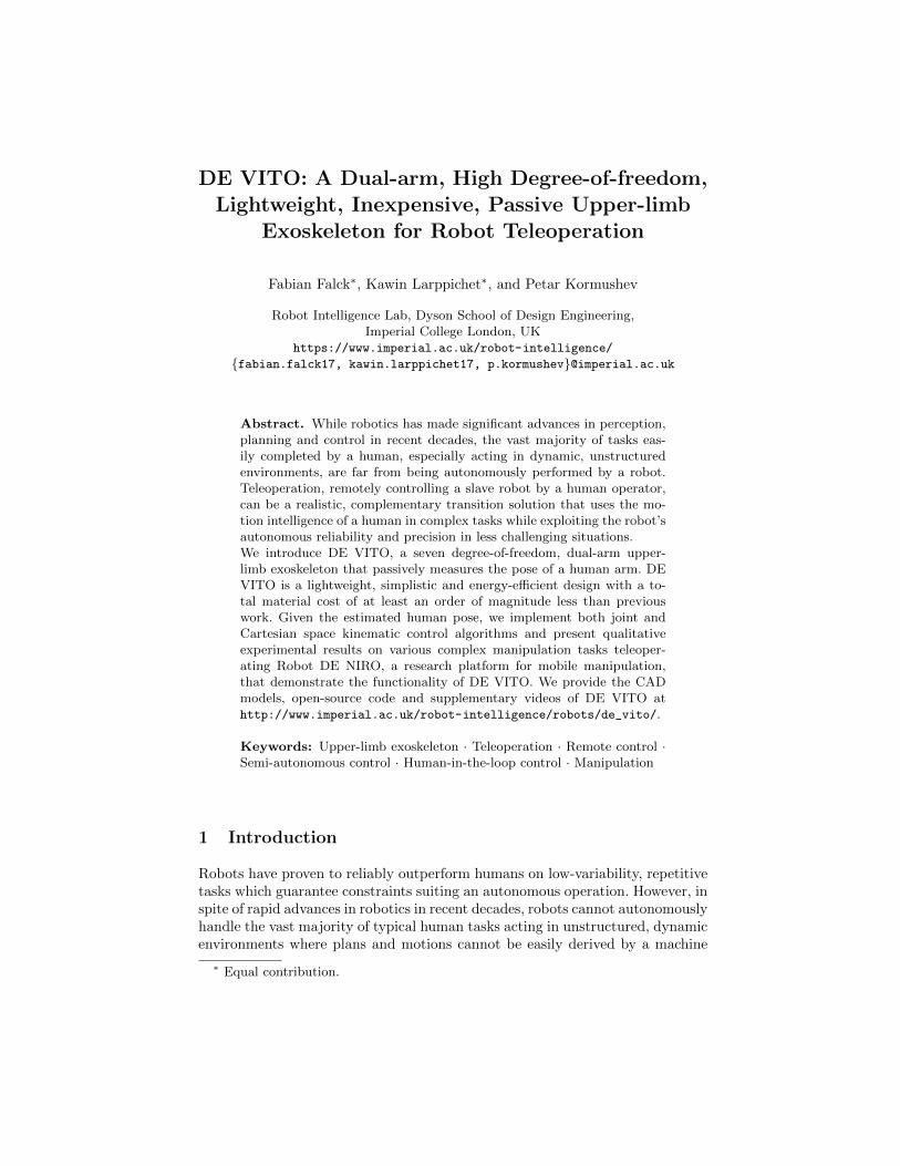
Moreover, we want to highlight three particularly promising mechanisms tomeasure internal rotation and briefly discuss the differences to our design, allillustrated in Fig. 2. Perry et al. propose a semi-circular bearing design whichisolates each joint (no interacting joint measurements in one-dimensional rota-tions) allowing a precise, isolated measurement [16]. However, this design is bothheavy (≈ 10 kg in total) and expensive. In comparison, the Toyota T-HR3 Mas-ter Maneuvering System is linked by four bars and therefore requires at leastfour revolute joints and numerous moving parts to operate, making its designoverly complicated [1]. Kim et al. propose a design with non-90-degree linkage ofrotation axes, which is based on only three revolute joints (like ours). However,in any arm motion, multiple joints are involved in the measurement process,overcomplicating the procedure [12]. In comparison, our design aims at a sim-plistic (few moving parts), lightweight and inexpensive (one single joint with anencoder used in [16] [1] [12] has a cost higher than the total material cost of ourwork) design without sacrificing in measurement precision.
3 Design and Implementation
3.1 Human arm motion
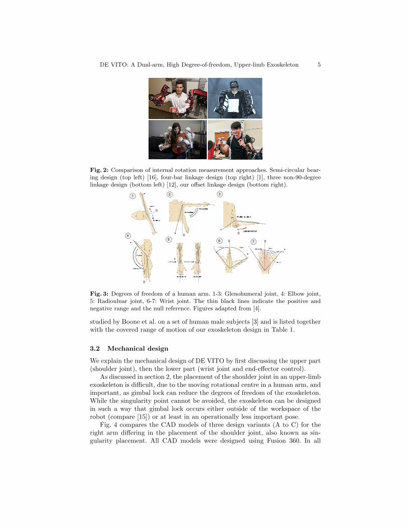
The purpose of DE VITO is to estimate the pose of a human arm by measuringits joint angles. In order to understand possible motions of a master operator, wefirst review the simple arm model (ignoring minor misalignment due to humanjoint translation) in human kinesiology. The human arm consists of seven degreesof freedom, illustrated in Fig. 3: Three rotations at the glenohumeral (shoulder)joint (1-3), one rotation at the elbow joint (4), one rotation at the radioulnarjoint on the forearm (5) and two rotations at the wrist joint (6-7). The Rangeof Motion (RoM) is defined as the maximum span of a human arm in positiveand negative direction with regards to a given reference frame. It was empirically
DE VITO: A Dual-arm, High Degree-of-freedom, Upper-limb Exoskeleton 5
Figure 3: comparison of internal rotation measurement mechanism. Semi-circular guideway (top left) [4], Four-bars linkages (top right) ADDIN RW.CITE{{doc:5b9b02cde4b09ad10da468e0 EvanAckerman 2017}}[20], three none-90-degree linkage (bottom left)[21], offset linkage (bottom right)
Fig. 2: Comparison of internal rotation measurement approaches. Semi-circular bear-ing design (top left) [16], four-bar linkage design (top right) [1], three non-90-degreelinkage design (bottom left) [12], our offset linkage design (bottom right).
65
Figure SEQ Figure \* ARABIC 1: Human arm motion ADDIN RW.CITE{{doc:5a94859ee4b06ab1c08d3613 [NoInformation] 2015}}[15]
31
4
2
7
+
-
-+
-
+
0
-
+
0-
+
0
-
+0
-
+ 0
0
Fig. 3: Degrees of freedom of a human arm. 1-3: Glenohumeral joint, 4: Elbow joint,5: Radioulnar joint, 6-7: Wrist joint. The thin black lines indicate the positive andnegative range and the null reference. Figures adapted from [4].
studied by Boone et al. on a set of human male subjects [3] and is listed togetherwith the covered range of motion of our exoskeleton design in Table 1.
3.2 Mechanical design
We explain the mechanical design of DE VITO by first discussing the upper part(shoulder joint), then the lower part (wrist joint and end-effector control).
As discussed in section 2, the placement of the shoulder joint in an upper-limbexoskeleton is difficult, due to the moving rotational centre in a human arm, andimportant, as gimbal lock can reduce the degrees of freedom of the exoskeleton.While the singularity point cannot be avoided, the exoskeleton can be designedin such a way that gimbal lock occurs either outside of the workspace of therobot (compare [15]) or at least in an operationally less important pose.
Fig. 4 compares the CAD models of three design variants (A to C) for theright arm differing in the placement of the shoulder joint, also known as sin-gularity placement. All CAD models were designed using Fusion 360. In all

6 F. Falck et al.
Table 1: Comparison of the Range of Motion (RoM) between a human arm [3] and ourproposed exoskeleton design. The first value of RoM represents maximum positive, thesecond maximum negative span in degrees with regards to the given reference framein Fig. 3.
Anatomicpart
Joint description andtype
Motion description Human armRoM [deg.]
ExoskeletonRoM [deg.]
Coverage per-centage [%]
ShoulderGlenohumeral joint(ball and socketjoint)
Flexion/Extension (158,53) (110,55) 78Adduction/Abduction (0,170) (0,110) 64Medial/Lateral rotation (70,90) (110,110) 100
Elbow Elbow joint (hingejoint)
Flexion/Extension (146,0) (110,110) 75
Forearm Radioulnar joint(pivot joint)
Pronation/Supination (71,84) (110,110) 100
WristWrist joint (saddlejoint)
Flexion/Extension (73,71) (110,55) 88Adduction/Abduction (33,19) (25,180) 100
three renderings, the camera pose is the same with gravity pointing downwards.The green arrows indicate rotational degrees of freedom. The three variants areshown in the pose of their kinematic singularity, occurring when the rotationalaxis along the upper-arm linkage (joint 3) is colinear with the first rotationalaxis at the the shoulder joint (joint 1). The red arrows indicate the rotational di-rection of this kinematic singularity. In variant A, gimbal lock occurs when botharm linkages point fowards and are colinear with the sagittal axis and removesthe rotational degree of freedom within the transverse plane, which is highlyunfavourable as it lies in the most used workspace area of a robot. In variantB, gimbal lock occurs when both arm linkages point outwards being colinearwith the frontal axis, prohibiting a rotational movement in the transverse plane.While this pose is infrequent during normal operation, it can be relevant to spe-cific manipulation tasks, such as picking up an object and placing it in a box onthe side of the robot. In variant C, gimbal lock occurs in the “relaxed pose” whenboth arm linkages point downwards, being colinear with the longitudinal axisand prohibiting rotational movement in the frontal plane. This singularity poseis by far the most favorable for two reasons: First, operation is unlikely in thispose. Second, it is outside of the workspace of most upper-body manipulationrobots, such as the Baxter arms of DE NIRO which we use in the experimentalsection. Therefore, we chose variant C for our final design.
The lower part of the exoskeleton is illustrated in Fig. 6. It was designed insuch a way that the forearm rotational axis (pronation/supination; blue dashedline) is perpendicular with the pitch and yaw axis of the controller (purpledashed lines) which allows a comfortable and ergonomic motion to rotate theend-effector. On top of the first joint, we mount a Nunchuk controller typicallyused as a controller for a Nintendo Wii game console. The Nunchuk’s two but-tons are mapped to open and close a gripper and, in the case of an emergency, toimmediately disable teleoperation (Baxter arms remain on last published coor-dinates) in accordance with the industrial robot ISO 10218. The small joystick,which is controllable by the thumb, is used for fine manipulation movements inthe transverse plane.

DE VITO: A Dual-arm, High Degree-of-freedom, Upper-limb Exoskeleton 7
A
B
C
Fig. 4: CAD models of three design variants (right arm only) for the shoulder joint.The green arrows indicate rotational degrees of freedom, the red arrows indicate therotational direction of kinematic singularity, if the rotational axis along the upper armlinkage is colinear with the last rotational axis at the shoulder joint. Variant C is chosenas our final design. Source of right-hand image: [13].
The complete mechanical design (CAD model and kinematic diagram) is il-lustrated in Fig. 5. As before, the green arrows indicate the seven rotationaldegrees of freedom of the design. Its corresponding Denavit-Hartenberg (DH)parameters are listed in Table 2. The total weight of the design is 3.2 kg (in-cluding the central electronics board), with each arm contributing 0.85 kg. Thisfulfills our initial goal of a lightweight, portable design that can be easily carriedfor prolonged amounts of time in operation mode. With regards to manufactur-ing DE VITO, all seven joints were 3D printed from ABS+, particularly suitedfor robust designs and good at avoiding warping. For manufacturing the links,we use carbon fiber fishing rod with a diameter of approximately 18 mm.
Z6 Z7Z5
Z2
Z3Z4
Z0,1
upper linkage
lower linkage
X0,1
Fig. 5: CAD model of one arm of DE VITO (with-out central body) and its corresponding kinematic di-agram. The green arrows represent the seven degreesof freedom of the arm. The brown arrows represent theseven Z and the X vectors in DH notation. Note thatall other X and Y vectors follow from the right-handrule and the initial coordinate frame.
Index i ai αi di θi1 0 0 0 θ12 0 π
20 θ2
3 0 π2
0.37 θ34 0 −π
20 θ4
5 0 π2
0.33 θ56 0 −π
2−0.07 θ6
7 0 π2−0.07 θ7
Table 2: DH table of DEVITO. ai represents thelength of the common normalof joint axes i and (i− 1), αirepresents the angle betweentwo adjacent joint axes, anddi represents the offset alongZi−1 to the common normal.
The electronic components of the exoskeleton mainly comprises one Arduinomega, one MPU6050 breakout, one I2C multiplexer, two terminal blocks, andpotentiometers described below. All components except for the potentiometersare mounted on a central circuit body covered in a plastic frame and worn on the

8 F. Falck et al.
Figure 5: Wrist joint design and end-effector controller
Open/close the gripper
Emergency stop
Fine manipulation (pitch and yaw)
RL
C C
Z Z
Figure 12: buttons mapping of both right and left Nunchuk controller
Fig. 6: CAD model of the lower part of DE VITO (left) and Nunchuk interface tocontrol an end-effector (right). The green arrows indicate the rotational degrees offreedom.
Fig. 7: Circuit board body (left), and corresponding wiring diagram (right) of DEVITO. The circuit board’s main components are one Arduino mega, one I2C multi-plexer, one MPU6050 breakout, and two terminal blocks.
back of the operator. A program running on the Arduino mega reads all sensormeasurements and forwards them to a ROS node to compute the forward andinverse kinematics, as explained in section 3.3. In order to use this very inex-pensive and energy-efficient micro controller, we conducted a low-level hardwareand code optimization by 1) parallelizing potentiometer measurements with aninterrupt handle 2) increasing the clock speed of the Arduino mega to the max-imum, yet stable value 3) adjusting the encryption and minimizing the numberof bytes during serial communication from 63 to 23 bytes per reading sample.Doing so, we achieve an effective sampling rate of the serial communication of720 Hz, a ten-times increase compared to before the optimization, which is suf-ficient for reactive, precise feedback for the manipulation tasks in section 4.The MPU6050 is functioning as an IMU sensor. It allows to measure the yawof the operator (rotation around the longitudinal axis) and therefore enables, ifrequired, the slave-robot to turn on the spot. The I2C multiplexer is requiredto communicate with multiple same-address devices and furthermore allows ex-tending DE VITO with additional sensors in future work. The circuit boardbody together with its corresponding wiring diagram is illustrated in Fig. 7.
In order to measure the joint angles, we use seven rotary potentiometers perarm, omitting expensive encoders in the related work, with an electrical angleof rotation of 260 degrees, being sufficient to cover the range of motion of all ex-oskeleton joints. Due to the limitation of the Arduino mega to 10 bits per analogsignal, the resolution of the potentiometers is limited to 260 deg.
210 ≈ 0.25 degree. In

DE VITO: A Dual-arm, High Degree-of-freedom, Upper-limb Exoskeleton 9
our experiments, we found this sensitivity to be more than sufficient for smooth,precise teleoperation by a human.
The approximate total material cost of the design is 200 GBP, including3D printing materials (≈ 70 GBP), carbon tubes and mechanical parts (≈ 60GBP) and electronic parts (≈ 70 GBP), making our design at least an order ofmagnitude less expensive than prior exoskeleton designs discussed in section 2.
3.3 Kinematic Control algorithm and Calibration
In the following, we define the kinematic mapping procedures from the exoskele-ton pose to the robot pose which we further explore in the experimental section.In the following, θmaster
i and θslavei refer to the i-th joint angle of the master
(exoskeleton) and the slave (e.g. Robot DE NIRO), respectively.(1) Joint space one-to-one: The simplest way to align the two spaces spaces
is by mapping each angle one-to-one as follows:θslavei = θmaster
i + θoffseti , where θoffset
i is an offset angle of joint i that accountsfor the difference in the null reference in both spaces. From the operator’s per-spective, this control procedure is most intuitive, as, for example, a rotation ofthe i-th exoskeleton joint by an angle β directly results in a rotation of the i-throbot arm joint by β. However, it comes at the disadvantage that the range ofmotion of the master operator (human) limits the range of motion of the slave(robot), although the latter is typically larger.
(2) Joint space scaled : To overcome this shortcoming, we use joint-specificfactors ci that linearly scale the mapping as follows:θslavei = ci ∗ θmaster
i + θoffseti . By upscaling the master angles, the operator can
access a larger range of motion of the slave robot. However, controlling the slaverobot this way is less intuitive and is therefore subject to experiments.
(3) Cartesian space: In addition to the joint space control procedures, we pro-vide a more high-level, Cartesian control approach controlling the end-effectorpose of the slave robot P slave
end-effector, given the pose of the exoskeleton’s end-effector Pmaster
end-effector. The control procedure consists of three steps: First, we calcu-late the slave’s end-effector pose (6 DOFs) as follows: P slave
end-effector = Pmasterend-effector+
doffset, where doffset is an offset pose to guarantee operation in the slave robot’sworkspace. This remains one DOF undefined (nullspace), which is why we imposea constraint on the elbow joint, fixing it in a specific rotation. Fig. 8 illustratestwo different elbow joint constraints which can be switched between by the userdepending on the exact manipulation task at hand. Third, we use Robot DENIRO’s inverse kinematics solver to compute the joint angles and actuate ac-cordingly.
4 Experiments
In the following, we describe our qualitative experiments and results that demon-strate DE VITO’s general functionality. The experiments apply the exoskeletonto teleoperate in complex manipulation tasks which would require – if at all
10 F. Falck et al.
Figure 11: Cartesian mapping example Horizontal gripping posture (top), Vertical gripping posture (bottom)
1 2
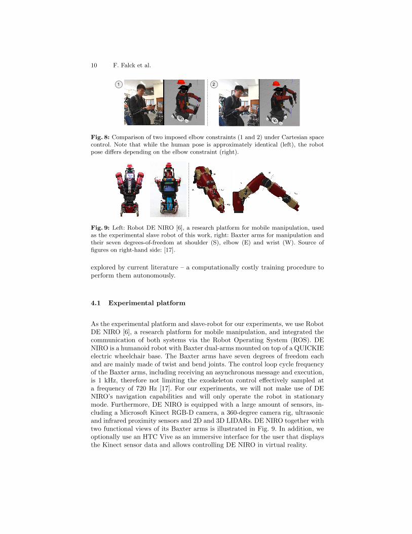
Fig. 8: Comparison of two imposed elbow constraints (1 and 2) under Cartesian spacecontrol. Note that while the human pose is approximately identical (left), the robotpose differs depending on the elbow constraint (right).
Fig. 9: Left: Robot DE NIRO [6], a research platform for mobile manipulation, usedas the experimental slave robot of this work, right: Baxter arms for manipulation andtheir seven degrees-of-freedom at shoulder (S), elbow (E) and wrist (W). Source offigures on right-hand side: [17].
explored by current literature – a computationally costly training procedure toperform them autonomously.
4.1 Experimental platform
As the experimental platform and slave-robot for our experiments, we use RobotDE NIRO [6], a research platform for mobile manipulation, and integrated thecommunication of both systems via the Robot Operating System (ROS). DENIRO is a humanoid robot with Baxter dual-arms mounted on top of a QUICKIEelectric wheelchair base. The Baxter arms have seven degrees of freedom eachand are mainly made of twist and bend joints. The control loop cycle frequencyof the Baxter arms, including receiving an asynchronous message and execution,is 1 kHz, therefore not limiting the exoskeleton control effectively sampled ata frequency of 720 Hz [17]. For our experiments, we will not make use of DENIRO’s navigation capabilities and will only operate the robot in stationarymode. Furthermore, DE NIRO is equipped with a large amount of sensors, in-cluding a Microsoft Kinect RGB-D camera, a 360-degree camera rig, ultrasonicand infrared proximity sensors and 2D and 3D LIDARs. DE NIRO together withtwo functional views of its Baxter arms is illustrated in Fig. 9. In addition, weoptionally use an HTC Vive as an immersive interface for the user that displaysthe Kinect sensor data and allows controlling DE NIRO in virtual reality.
DE VITO: A Dual-arm, High Degree-of-freedom, Upper-limb Exoskeleton 11
Figure 14: Setup of the Brick stacking experiment
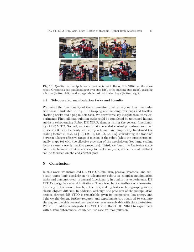
Fig. 10: Qualitative manipulation experiments with Robot DE NIRO as the slaverobot: Grasping a cup and handing it over (top left), brick stacking (top right), graspinga bottle (bottom left), and a peg-in-hole task with allen keys (bottom right).
4.2 Teleoperated manipulation tasks and Results
We tested the functionality of the exoskeleton qualitatively on four manipula-tion tasks, illustrated in Fig. 10: Grasping and handing over cups and bottles,stacking bricks and a peg-in-hole task. We drew three key insights from these ex-periments: First, all manipulation tasks could be completed by untrained humansubjects teleoperating Robot DE NIRO, demonstrating the general functional-ity of DE VITO. Second, we found that the scaled control procedure describedin section 3.3 can be easily learned by a human and empirically fine-tuned thescaling factors c1 to c7 as {1.0, 1.2, 1.5, 1.0, 1.3, 1.5, 1.5}, considering the trade-offbetween a larger effective range of motion of the robot (what the exoskeleton ac-tually maps to) with the effective precision of the exoskeleton (too large scalingfactors cause a overly reactive procedure). Third, we found the Cartesian spacecontrol to be most intuitive and easy to use for subjects, as their visual feedbackcan be focussed on the end-effector pose.
5 Conclusion
In this work, we introduced DE VITO, a dual-arm, passive, wearable, and sim-plistic upper-limb exoskeleton to teleoperate robots in complex manipulationtasks and demonstrated its general functionality in qualitative experiments. DEVITO’s design has several limitations: There is no haptic feedback on the exertedforce, e.g. in the form of touch, to the user, making tasks such as grasping soft orelastic objects difficult. In addition, although the precision of the manipulationactions through DE VITO is remarkable given its inexpensive, low-energy andlight-weight design, further research and experiments are required to evaluatethe degree to which general manipulation tasks are solvable with the exoskeleton.We will in addition integrate DE VITO with Robot DE NIRO to experimentwith a semi-autonomous, combined use case for manipulation.

12 F. Falck et al.
References
1. Ackerman, E.: Toyota Gets Back Into Humanoid Robots With NewT-HR3. https://spectrum.ieee.org/automaton/robotics/humanoids/
toyota-gets-back-into-humanoid-robots-with-new-thr3 (2018)2. Ackerman, E., Guizzo, E.: DARPA Robotics Challenge Finals: Rules and
Course. https://spectrum.ieee.org/automaton/robotics/humanoids/
drc-finals-course (2018)3. Boone, D.C., Azen, S.P.: Normal range of motion of joints in male subjects. The
Journal of Bone and Joint Surgery 61(5), 756–759 (1979)4. clinicalgate.com: Upper Limb - General description. https://clinicalgate.com/
upper-limb-2/ (2015)5. Debrunner, T., Saeedi, S., Kelly, P.H.: Auke: Automatic kernel code generation
for an analogue simd focal-plane sensor-processor array. ACM Transactions onArchitecture and Code Optimization (TACO) 15(4), 59 (2019)
6. Falck, F., Doshi, S., Smuts, N., Lingi, J., Rants, K., Kormushev, P.: Human-centered manipulation and navigation with Robot DE NIRO. In: Intelligent Robotsand Systems (IROS) Workshop Towards Robots that Exhibit Manipulation Intel-ligence, 2018 IEEE/RSJ International Conference on. (2018)
7. Fang, B., Guo, D., Sun, F., Liu, H., Wu, Y.: A robotic hand-arm teleoperation sys-tem using human arm/hand with a novel data glove. In: Robotics and Biomimetics(ROBIO), 2015 IEEE International Conference on. pp. 2483–2488. IEEE (2015)
8. Gopura, R., Kiguchi, K., Bandara, D.: A brief review on upper extremity roboticexoskeleton systems. In: Industrial and Information Systems (ICIIS), 2011 6thIEEE International Conference on. pp. 346–351. IEEE (2011)
9. Hirche, S., Buss, M.: Human-oriented control for haptic teleoperation. Proceedingsof the IEEE 100(3), 623–647 (2012)
10. Jarrasse, N., Morel, G.: Connecting a human limb to an exoskeleton. IEEE Trans-actions on Robotics 28(3), 697–709 (2012)
11. Kemp, C.C., Edsinger, A., Torres-Jara, E.: Challenges for robot manipulation inhuman environments [grand challenges of robotics]. IEEE Robotics & AutomationMagazine 14(1), 20–29 (2007)
12. Kim, B., Deshpande, A.D.: Controls for the shoulder mechanism of an upper-bodyexoskeleton for promoting scapulohumeral rhythm. In: Rehabilitation Robotics(ICORR), 2015 IEEE International Conference on. pp. 538–542. IEEE (2015)
13. Krishnan, R.H., Devanandh, V., Brahma, A.K., Pugazhenthi, S.: Estimation ofmass moment of inertia of human body, when bending forward, for the design ofa self-transfer robotic facility. J. Eng. Sci. Technol 11(2), 166–176 (2016)
14. Lu, J., Haninger, K., Chen, W., Gowda, S., Tomizuka, M., Carmena, J.M.: Designof a passive upper limb exoskeleton for macaque monkeys. Journal of DynamicSystems, Measurement, and Control 138(11), 111011 (2016)
15. Nef, T., Mihelj, M., Kiefer, G., Perndl, C., Muller, R., Riener, R.: ARMin-Exoskeleton for arm therapy in stroke patients. In: Rehabilitation Robotics, 2007.ICORR 2007. IEEE 10th International Conference on. pp. 68–74. IEEE (2007)
16. Perry, J.C., Rosen, J., Burns, S.: Upper-limb powered exoskeleton design.IEEE/ASME transactions on mechatronics 12(4), 408–417 (2007)
17. Robotics, R.: Baxter Research Robot SDK Wiki - Arm Control Overview andHardware Specifications. http://sdk.rethinkrobotics.com/wiki/Arm_Control_Overview, http://sdk.rethinkrobotics.com/wiki/Hardware_Specifications
(2015)