DDP-Honors AND DDP-Tech · 2018-08-08 · Drawing & Sketching Oblique A type of sketch involving a...
45
To view the information in this document, click the Page tabs (Ex. Design Process, Travel Mug, etc.) along the side. Then you can zoom in and out on items by holding the control key and scrolling with the wheel on your mouse. To pan (slide) back and forth on the page, you can push in the scroll wheel on the mouse and move in the desired direction. DDP - Honors AND DDP - Tech Class Notebook HomePage Tuesday, November 16, 2010 3:35 PM Class Notebook_DDP Page 1
Transcript of DDP-Honors AND DDP-Tech · 2018-08-08 · Drawing & Sketching Oblique A type of sketch involving a...

To view the information in this document, click the Page tabs(Ex. Design Process, Travel Mug, etc.) along the side. Then you can zoom in and out on items by holding the control key and scrolling with the wheel on your mouse.
To pan (slide) back and forth on the page, you can push in the scroll wheel on the mouse and move in the desired direction.
DDP-Honors AND DDP-Tech
Class NotebookHomePageTuesday, November 16, 2010 3:35 PM
Class Notebook_DDP Page 1

Extra Work and Year-long project ideas, images, etc.Things to work on when you are done early with a project.
Do a Google image search for Inventor ideas, Inventor models, Inventor projects, etc. to get ideas.
Redesign your phone•Make a case for your phone•Re-create something in the room (ex. Stapler, computer, tape dispenser, etc)•Improve a product in your life that you wish was different. Make that change. (ex. "I wish my phone had a holder for a small stylus pen")
•
Instruments•Tools•Vehicles•
A few ideas:Work on it from September to June
Above & Beyond!!Wednesday, September 26, 2012 11:02 AM
Class Notebook_DDP Page 2

Class Notebook_DDP Page 3

1st Quarter
CATEGORY TERM DEFINITION GRAPHIC
Design CAD Computer-Aided Design or Computer-Aided Drafting: 1. For design, the use of a computer to assist in the process of designing a part, circuit, building, etc. 2. For drafting, the use of a computer to assist in the process of creating, storing, retrieving, modifying, plotting, and communicating a technical drawing.
Drawing & Sketching
Oblique A type of sketch involving a combination of a flat, orthographic front with depth lines receding at a selected angle, usually 45 degrees.
Drawing & Sketching
Isometric A form of pictorial sketch in which all three drawing axes form equal angles of 120 degrees with the plane of projection.
Drawing & Sketching
Orthographic (projection)
A method of representing three-dimensional objects on a plane having only length and breadth. Also referred to as Right Angle Projection.
Drawing & Sketching
Sketches –thumbnail and annotated
Thumbnail-A rough or unfinished drawing or painting.
Annotated - sketch w/ notations & dimensions.
Drawing & Sketching
Annotate To add explanatory notes to.
Drawing & Sketching
Drawing Sheet A document used to display technical drawings
Inventor Degrees of Freedom
The variables by which an object can move. In assemblies, an object floating free in space with no constraints to another obj ect can be moved along three axes of translation and around three axes of rotation. Such a body is said to have six degrees of freedom.
Design Design Process A systematic problem-solving strategy, with criteria and constraints, used to develop many possible solutions to solve a problem or satisfy human needs and wants and to winnow (narrow) down the possible solutions to one final choice.
Inventor Absolute & Relative Coordinates
(Absolute from 0,0 or Relative from another coordinate)
Inventor Constraint(s)
(Geometric [2D]&Assembly [3D])
Geometric - constraints used in 2D sketch mode, such as collinear, coincident, parallel, concentric,etc
Assembly - constraints used in 3D mode, while assembling parts, such as Mate, Flush, Insert, Tangent, and Angle
Design Constraint(s) (Design)
1. A limit to a design process. Constraints may be such things as appearance, funding, space, materials, and human capabiliti es. 2. A limitation or restriction.
Design Engineers Notebook
An engineering notebook is a book in which an engineer will formally document, in chronological order, all of his/her work th at is associated with a specific design project.
Inventor Axis 1. An imaginary line through a body, about which it rotates. 2. An imaginary line about which a regular figure is symmetrical ly arranged. 3. A fixed reference line for the measurement of coordinates.
Inventor Plane (work plane)
A flat surface on which a straight line joining any two points would wholly lie.
Drawing & Sketching
Scale A proportion between two sets of dimensions used in developing accurate, larger or smaller prototypes, or models of design id eas. Examples: 1:1 2:1 ¾
Drawing & Sketching
Title block A table located in the bottom right-hand corner of an engineering drawing that identifies, in an organized way, all of the necessary information that is not give n on the drawing itself. Also referred to as a title strip.
Design Engineer A person who is trained in and uses technological and scientific knowledge to solve practical problems.
Drawing & Sketching
Dimension A measurable extent, such as the three principal dimensions of an object is width, height, and depth.
Other:
Inventor Fillet, chamfer, etc
Fillet: An inside radius between two intersecting planes.
Chamfer: A small angled surface formed between two surfaces.
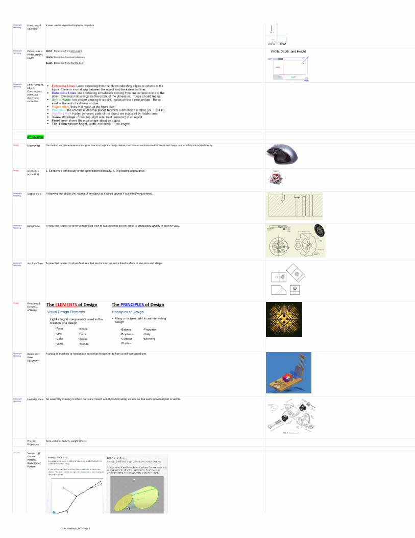
Drawing & Front, top, & 3 views used in a typical orthographic projection
VOCABULARYThursday, October 20, 2011 8:38 AM
Class Notebook_DDP Page 4
Drawing & Sketching
Front, top, & right side
3 views used in a typical orthographic projection
Drawing & Sketching
Dimensions –Width, Height, Depth
Width: Dimension from left to right
Height: Dimension from top to bottom
Depth: Dimension from front to back
Drawing & Sketching
Lines – Hidden, Object, Construction, extension, dimension, centerline
2nd Quarter
Design Ergonomics The study of workplace equipment design or how to arrange and design devices, machines, or workspace so that people and thing s interact safely and most efficiently.
Design Aesthetics (esthetics)
1. Concerned with beauty or the appreciation of beauty. 2. Of pleasing appearance.
Drawing & Sketching
Section View A drawing that shows the interior of an object as it would appear if cut in half or quartered.
Drawing & Sketching
Detail View A view that is used to show a magnified view of features that are too small to adequately specify in another view.
Drawing & Sketching
Auxiliary View A view that is used to show features that are located on an inclined surface in true size and shape.
Design Principles & Elements of Design
Drawing & Sketching
Assembled View (Assembly)
A group of machine or handmade parts that fit together to form a self -contained unit.
Drawing & Sketching
Exploded View An assembly drawing in which parts are moved out of position along an axis so that each individual part is visible.
Physical Properties
Area, volume, density, weight (mass)
Inventor Sweep, Loft, Circular Pattern,Rectangular Pattern
Class Notebook_DDP Page 5

Circular Pattern,Rectangular Pattern
Drawing & Sketching
Center mark, centerline bisector
3rd QuarterReverse Engineering
Caliper A measuring instrument having two usually adjustable jaws used especially to measure diameter or thickness.
Reverse Engineering
Precision The method of formation, operation, or procedure exhibited in a given instance.
Reverse Engineering
Reverse engineering –VSF product analysis
The process of taking something apart and analyzing its workings in detail.
Reverse Engineering
Histogram A graph of vertical bars representing the frequency distribution of a set of data.
Reverse Engineering
Statistics –Mean, Median, Mode
Collection of methods for planning experiments, obtaining data, organizing, summarizing, presenting, analyzing, interpreting, and drawing conclusions based on data.
Drawing & Sketching
Working drawing
Drawings that convey all of the information needed to manufacture and assemble a design.
Drawing & Sketching
Radius A straight line from the center to the circumference of a circle or sphere.
Drawing & Sketching
Diameter A straight line passing from side to side through the center of a circle or sphere.
Reverse Engineering
Tolerance (unilateral, bilateral, stacked)
A tolerance is an acceptable amount of dimensional variation that will still allow an object to function correctly.
4th QuarterInventor Countersink A conical-shaped recess around a hole, often used to receive a tapered screw.
Inventor Counter bore A cylindrical recess around a hole, usually to receive a bolt heard or nut.
Class Notebook_DDP Page 6

Inventor Counter bore A cylindrical recess around a hole, usually to receive a bolt heard or nut.
Decision Matrix
A tool for systematically ranking alternatives according to a set of criteria.
Design Brief A written plan that identifies a problem to be solved, its criteria, and its constraints. The design brief is used to encoura ge thinking of all aspects of a problem before attempting a solution.
Design Invent vs. Innovate
Invent - a new design or ideaInnovate - modify or improve an existing design
Inventor Hole callouts
Product Evolution
The way a product evolves over time; progressing in technology, efficiency, and other improvements.
Design Product Lifecycle*
Stages a product goes through from concept and use to eventual withdrawal from the market place.
Design Mockup A model or replica of a machine or structure for instructional or experimental purposes. Also referred to as an Appearance Mo del.
Design Prototype A full-scale working model used to test a design concept by making actual observations and necessary adjustments.
Technical Report
A document that conveys the results of scientific and technical research, and provides recommendations for action.
Parametric Modeling*
A CAD modeling method that uses parameters to define the size and geometry of features and to create relationships between fe atures. Changing a parameter value updates all related features of the model at once. (Ex. D2=D1=4)
Portfolio A collection of one's best work.
Virtual teaming A group of people that rely primarily or exclusively on electronic forms of communication to work together in accomplishing g oals.
Class Notebook_DDP Page 7

Virtual teaming A group of people that rely primarily or exclusively on electronic forms of communication to work together in accomplishing g oals.
Pasted from <file:///H:\Teaching%20Files\2011-2012\DDP%20Honors\DDP%20terms_by%20quarter.xls>
Class Notebook_DDP Page 8

No more than 3 cubes in any direction1.
Avoid flat pieces2.
4-6 cubes per collection / 27 cubes total3.
5 collections4.
No repeated shape5.
No edge joins6.
Design Constraints:
Check your Dimensioning page in the Class Notebook for guidelines and rules to follow.
Cube Puzzle ProjectThursday, September 27, 2012 10:53 AM
Class Notebook_DDP Page 9

Views, Dimensions, Axes, & PlanesThursday, October 15, 2015 10:24 AM
Class Notebook_DDP Page 10
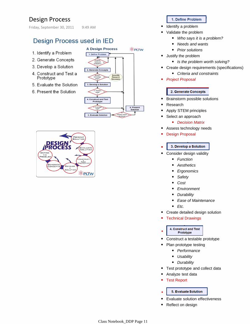
Identify a problem•
Who says it is a problem?•Needs and wants•Prior solutions•
Validate the problem•
Is the problem worth solving?•Justify the problem•
Criteria and constraints•Create design requirements (specifications)•
Project Proposal•
Brainstorm possible solutions•Research•Apply STEM principles•
Decision Matrix•Select an approach•
Assess technology needs•Design Proposal•
•
Function•Aesthetics•Ergonomics•Safety•Cost•Environment•Durability•Ease of Maintenance•Etc.•
Consider design validity•
Create detailed design solution•Technical Drawings•
•
Construct a testable prototype•
Performance•Usability•Durability•
Plan prototype testing•
Test prototype and collect data•Analyze test data•Test Report•
•
Evaluate solution effectiveness•
Recommend improvements•Reflect on design •
Design ProcessFriday, September 30, 2011 9:49 AM
Class Notebook_DDP Page 11

Recommend improvements•
[Return to prior design process steps, if necessary]
•
Revise design documents•
Optimize/Redesign the solution•
Project Recommendations•
•
Project Portfolio•Document the project•
Formal Presentation•Communicate the project•
Class Notebook_DDP Page 12
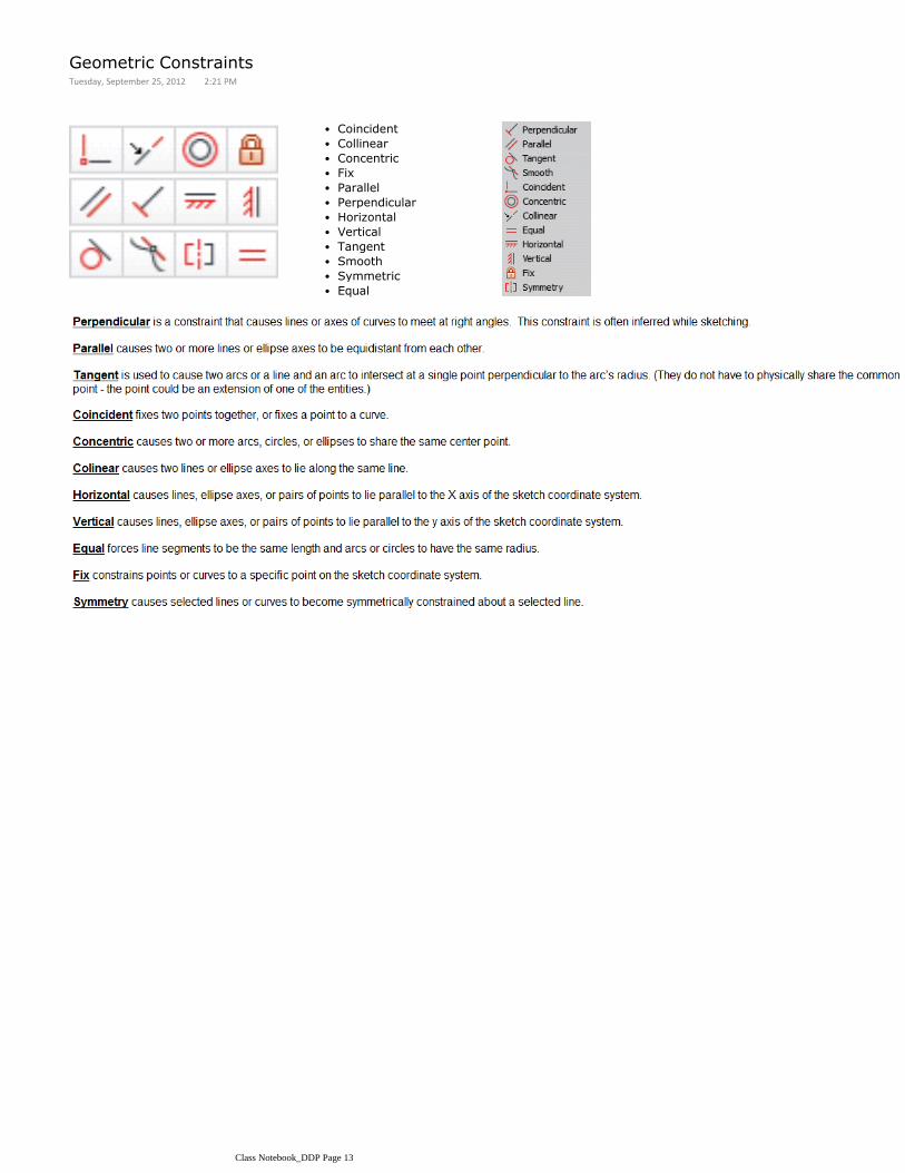
Coincident•
Collinear•
Concentric•
Fix•
Parallel•
Perpendicular•
Horizontal•
Vertical•
Tangent•
Smooth•
Symmetric•
Equal•
Geometric ConstraintsTuesday, September 25, 2012 2:21 PM
Class Notebook_DDP Page 13
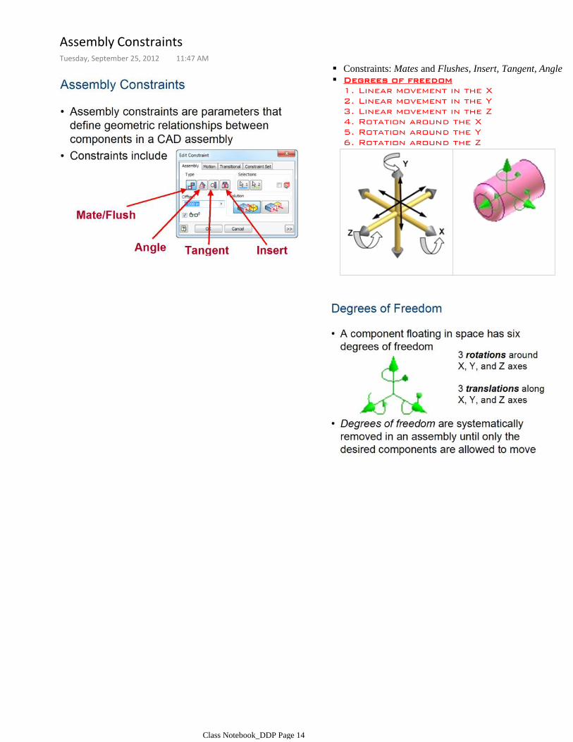
Constraints: Mates and Flushes, Insert, Tangent, Angle
Degrees of freedom
1. Linear movement in the X
2. Linear movement in the Y
3. Linear movement in the Z
4. Rotation around the X
5. Rotation around the Y
6. Rotation around the Z
Assembly ConstraintsTuesday, September 25, 2012 11:47 AM
Class Notebook_DDP Page 14

1. Overall dimensions for W,H,D2. Do not OVER-dimension (#1 and #2)3. Dimensions go in ASCENDING order4. Dimension BETWEEN the views. (#7)5. Keep dimensions OFF of the object. (#5)
5 dimension rules I’m looking for are: (from Dimension Guidelines PPT - #)
DimensioningThursday, October 20, 2011 8:30 AM
Class Notebook_DDP Page 15

Extrude1.Revolve2.Fillets and Rounds3.Chamfers4.Editing Features5.Work Features6.Sweeps (under Advanced Skills)7.Circular Patterns8.Rectangular Patterns9.Mirror Patterns10.Hole Features11.Shell12.
Order in which we will complete tutorials: ○
Access the Inventor tutorials through the Computer icon on the Desktop. Then go to the D:/ drive (Thaw space) and double-click the .chm file called Inventor11.chm
Computer
Inventor Tutorials
Types of Constraints in Inventor- Geometric Constraints (2D constraints)- Assembly Constraints (3D constraints)
Constraint definition○
Create a folder in your TUTORIALS folder for EACH of the tutorials listed under Basic 3D
Inside ------> R:TechArtVol/Project Lead the Way/Students/DDP/Tutorials
Tutorials (Inventor)Friday, September 30, 2011 9:46 AM
Class Notebook_DDP Page 16

NO!YES !
ExtrudeWednesday, October 19, 2011 8:46 AM
Class Notebook_DDP Page 17

REMEMBER: Revolves need 2 things: □
Profile & Axis
Detached or floating axis-or-Attached axis (revolving on itself)
Avoid the "Apple"
Avoid the "football"
After completing up through the Additional Exercises, try creating a lamp base….and even a lamp shade!
RevolveWednesday, October 19, 2011 8:55 AM
Class Notebook_DDP Page 18
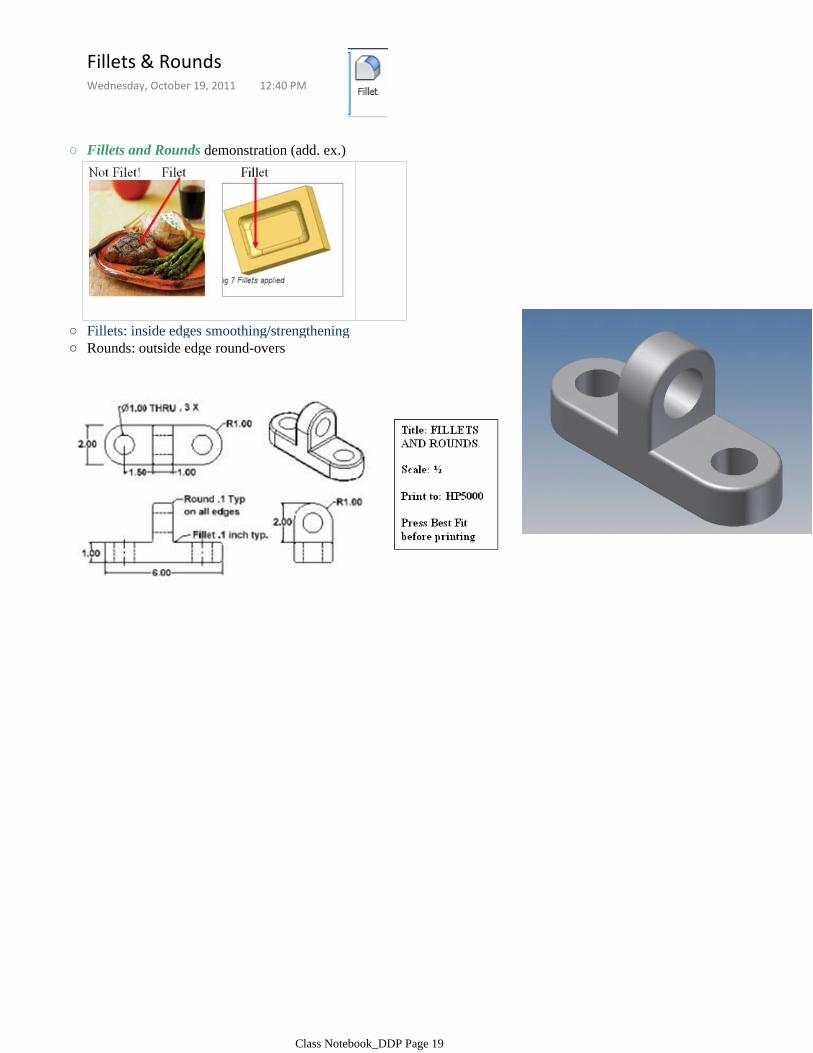
Fillets and Rounds demonstration (add. ex.)○
Fillets: inside edges smoothing/strengthening○
Rounds: outside edge round-overs○
Fillets & RoundsWednesday, October 19, 2011 12:40 PM
Class Notebook_DDP Page 19

Additional Exercise
ChamfersWednesday, October 26, 2011 2:32 PM
Class Notebook_DDP Page 20

Edit SKETCH- Will change something that happened in the 2D world (ex. Geometry like lines, arcs, circles)
Edit FEATURE - Will change something 3D about the object (ex. An extrusion depth, a fillet radius, a hole diameter or depth, etc)
Editing FeaturesMonday, November 07, 2011 8:24 AM
Class Notebook_DDP Page 21

Work Features includes 3 main items:Work Plane - Places a work plane within a model (work plane bisector, offset work plane, angled work planes1.Work Axis - Places an axis within a model 2.Work Point - Places a work point, reference point on a model3.
Work Features (Planes and Axes)
Work Features explained
Placing Work points, Work Axis, and Work Planes -----> 3 steps (tool, origin, orientation)
Work Planes: Cylinder bisector, offset, tangent
Slice Graphics (F7)
Work Plane /axis visibility (on/off)
Bird Feeder activity
Work FeaturesThursday, October 20, 2011 8:49 AM
Class Notebook_DDP Page 22

Additional Exercise - The Hanger
Sweeps (under Advanced Skills)
Wednesday, October 24, 2012 8:26 AM
Class Notebook_DDP Page 23

With the Additional Exercise, use a TANGENT WORK PLANE to establish the 3 items (peg, hole, and rectangular block). Sketch each item on an individual sketch, apply a 3D feature, and then proceed to a new sketch for the next item.
Circular PatternsMonday, November 07, 2011 8:24 AM
Class Notebook_DDP Page 24
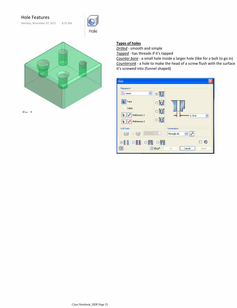
Types of holesDrilled - smooth and simpleTapped - has threads if it's tappedCounter bore - a small hole inside a larger hole (like for a bolt to go in)Countersink - a hole to make the head of a screw flush with the surface it's screwed into (funnel shaped)
Hole FeaturesMonday, November 07, 2011 8:25 AM
Class Notebook_DDP Page 25

ShellMonday, November 07, 2011 8:25 AM
Class Notebook_DDP Page 26
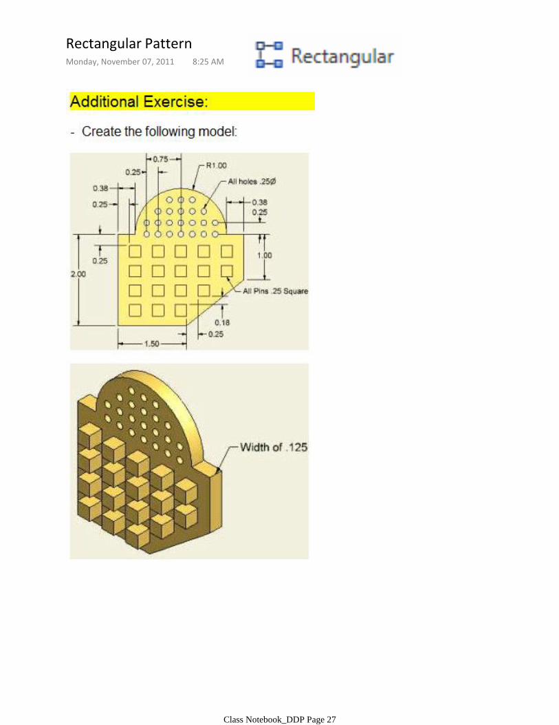
Rectangular PatternMonday, November 07, 2011 8:25 AM
Class Notebook_DDP Page 27
○
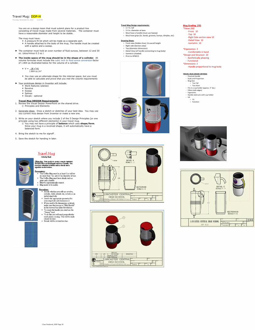
5-7 in. tall○
2-3 in. diameter at base○
Must have a handle (must use Sweep)○
Must have grips (Ex. bands, grooves, bumps, dimples, etc)○
Travel Mug Design requirements:
Front view (hidden lines) & overall height○
Right side (Section view)○
Top (diameter dimension)○
Detail View (of handle connecting to mug body)○
Isometric (shaded)○
Print to HP4015○
Drawing Sheet:
You are on a design team that must submit plans for a product line consisting of travel mugs made from several materials. The container must
have a reasonable diameter and height to be stable.
A pressure fit lid which will be made as a separate part.
A handle attached to the body of the mug. The handle must be created with a spline and a sweep.
The mug must have:
The container must hold an even number of fluid ounces, between 12 and 30 oz. (plus/minus 0.3 oz.)
►
V = (π r2 H)
1.804 oz./in3
You may use an alternate shape for the internal space, but you must be able to calculate and prove that you met the volume requirements
The inside space of the mug should be in the shape of a cylinder. All volume formulas must include the cubic inch to fluid ounce conversion factor
of 1.804 as illustrated below for the volume of a cylinder.
►
Work features (planes)
Revolve
Sweep
Splines
Decals - optional
Your prototype design in Inventor will include:►
Travel Mug DESIGN Requirements
Principles and Elementsi)
Review the Visual Design PowerPoint on the shared drive.1.
Generate ideas: Draw a sketch or sketches of your best idea. You may use you current mug design from Inventor or make a new one.
2.
You may not have a principle of balance which uses shape/form. Since your mug is a revolved shape, it will automatically have a
balanced form.
i)
Write on your sketch where you include 2 of the 5 Design Principles [or one principle using two different elements] in your travel mug.
3.
Bring the sketch to me for signoff .4.
Save the sketch for handing in later.5.
Mug Grading (70)
-Front 10-Top 10-Right Side section view 10-Detail View 10-Isometric 10
*Views (50)
-Comfortable in hand*Ergonomics 5
Aesthetically pleasing-
Functional-
*Design and Structure 10
-Handle proportional to mug body*Dimensions 5
Practical Handle-
Scale and Proportion-
Too Tall○
Too short○
Mug Size-
Fits in a cup holder (approx. 3" dia.)-
Fillets (safe edges)-
Ergonomic-
Handle obstructs with cup holder-
Fit○
Function○
Lid-
TRAVEL MUG GRADE CRITERIA
Travel Mug: DDP-HThursday, November 01, 2012 2:34 PM
Class Notebook_DDP Page 28
○
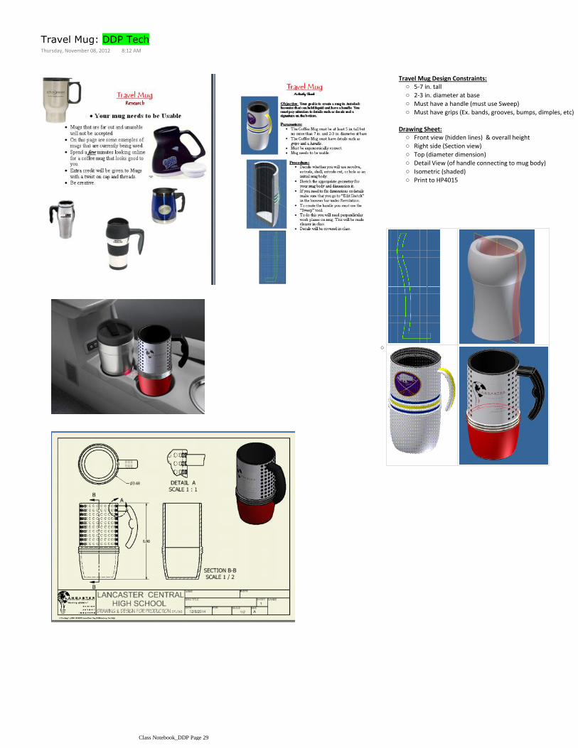
5-7 in. tall○
2-3 in. diameter at base○
Must have a handle (must use Sweep)○
Must have grips (Ex. bands, grooves, bumps, dimples, etc)○
Travel Mug Design Constraints:
Front view (hidden lines) & overall height○
Right side (Section view)○
Top (diameter dimension)○
Detail View (of handle connecting to mug body)○
Isometric (shaded)○
Print to HP4015○
Drawing Sheet:
Travel Mug: DDP TechThursday, November 08, 2012 8:12 AM
Class Notebook_DDP Page 29
Research & Investigation1.Sketching2.Inventor modeling3.Save as an .STL (See Saving as an STL page in Class Notebook) Name, period, and preferred color (ex. green_p3_SmithJ_Streit.stl )
4.
Submit into Dropbox folder on the R:/ drive 5.Create a Drawing Sheet of your ornament with overall dimensions indicated.
6.
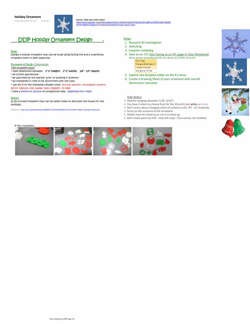
Steps: DDP Holiday Ornament Design .
Goal:Design a holiday ornament that can be hung using fishing line and a traditional ornament hook or bent paperclip.
Parameters/Design Constraints:The ornament must:* have dimensions between: 2”-3” (height) 2”-3” (width) 1/8” - 1/4” (depth)* be school appropriate* be approved by the teacher prior to building in Inventor* be completed in time to be 3D-printed with the class* use any 2 of the following complex tools: circular pattern, rectangular pattern, mirror feature, coil, sweep, hole, chamfer, or fillet* have a sketch or picture of prospective idea - submitted for credit
Result:A 3D printed ornament that can be taken home to decorate the house for the Holidays.
Pasted from <http://www.lancasterschools.org/86935117125733/lib/86935117125733/DDP_Holiday_Ornament_Design.doc>
Side Notes:Hole for hanging (diameter 1/16"-3/16")•You have 3 colors to choose from for the 3D print (red, white, or blue).•Don't worry about changing colors of surfaces in the .IPT - it's irrelevant.•Focus on the structure of the ornament•Details must be raised up or cut in to show up.•Don't make parts too thin - they will snap! (Too narrow, too shallow)•
Survey - Rate your color choicehttps://docs.google.com/a/lancasterschools.org/forms/d/e/1FAIpQLSfLwjIEFyrSPJPAJbE-6bkRp3jY8YnMnHCGhbusYjTXvdvAUA/viewform?usp=send_form
A few examples:
Holiday OrnamentFriday, November 18, 2011 11:06 AM
Class Notebook_DDP Page 30

Monday, November 29, 20109:13 AM
Do a SAVE COPY AS1.
Direct it to the correct directory (ex. STUDENT folder on your R:/ drive (TechArtVol - Holiday Ornament)2.
Switch file type to .stl3.
Choose OPTIONS4.
Change Centimeter to Inch5.
Name the file ( Put your name, preferred color, and period # in the file name
ex. Green_p3_SmithJ_Streit.stl6.
Within your Inventor part file (.ipt), you must:
--------------------------------------------------------------------------------------------------------------------------------
Place your file on the jump drive being passed around.
Saving as an .STL fileWednesday, November 30, 2011 9:53 AM
Class Notebook_DDP Page 31

IGNORE THIS>>>>>
Right click on the STL in your R:/ drive STUDENT folder [in your Holiday Ornament folder] Ex. Green_p3_SmithJ_Streit.stl
1.
Select Copy from the context menu2.
Go to the appropriate DROPBOX Ornament STL folder (ex. Holiday Ornament STLs ----> Period 2)3.
Paste your STL file in your period's folder4.
Putting the .STL in the appropriate DROPBOX folder:
Create a CAD model +1.Save as an STL2.Bring STL into Catalyst printer software 3.Process STL (divides it into the layers [.01"])4.Add to pack (you can place many parts on a pack)5.Send to printer (The software will give a readout of material and time)6.Hours later, retrieve part from the printer.7.
The 3D printing process explained (rapid prototyping) [video]+○
Class Notebook_DDP Page 32

Mist Fragrances is looking to add a new scent (cologne or perfume) to their new line of fragrances for
the holiday season. As a member of the Mist Fragrances team, it is your duty to develop, design,
model, and document a new bottle design for the company.
2"-5" tall○
.75"-3" wide○
.75" -3" deep○
The bottle should be:○
Must design for opposite sex - Guys do perfume and girls do cologne.○
The bottle must be made using: revolve, loft, coil, sweep, or some other complex feature.○
The bottle must have a hole for dispensing and a cap (pressure fit or thread on cap)○
The bottle should have a name or logo on it. It can be a decal (jpeg picture) or emboss. ○
You must show evidence of 2 Principles of Design and explain it in the documentation.○
Parameters and Design Constraints
Research & Investigation - Word document of pictures of existing designs1.15 thumbnail sketches2.1 quality annotated sketch of bottle AND cap3.Two Principles of Design evident4.A working drawing of the bottle and cap - with overall dimensions (A-size sheet) and section view(see example shown)
5.
Documentation / Deliverables
Print everything to the 4015 (Black and White in room 154)
Fragrance Bottle Vote
https://docs.google.com/forms/d/1HHf-5cAph2Ne87V3AHxVKTEsTxnHbAD_q_9-ShtPiF0/viewform?usp=send_form
Fragrance Bottle - DDP-HThursday, December 08, 2011 10:00 AM
Class Notebook_DDP Page 33

The ELEMENTS of Design The PRINCIPLES of Design
DESIGN is NO mistake! Products are created with an intent and purpose. Every product we own was designed with the core principles and elements of design in mind.
Look over the below PowerPoint.
Principles & Elements of Design PPT - Gives an explanation and example of each of the Principles AND ELEMENTS
ELEMENTS - The parts of a design that make it up. (Think of it as the Periodic Table of Elements - The Elements that make up our world) Elements are the building blocks of a design.
PRINCIPLES - Common ideas or concepts that make a design more appealing.
Principles & Elements of DesignWednesday, November 02, 2011 2:35 PM
Class Notebook_DDP Page 34
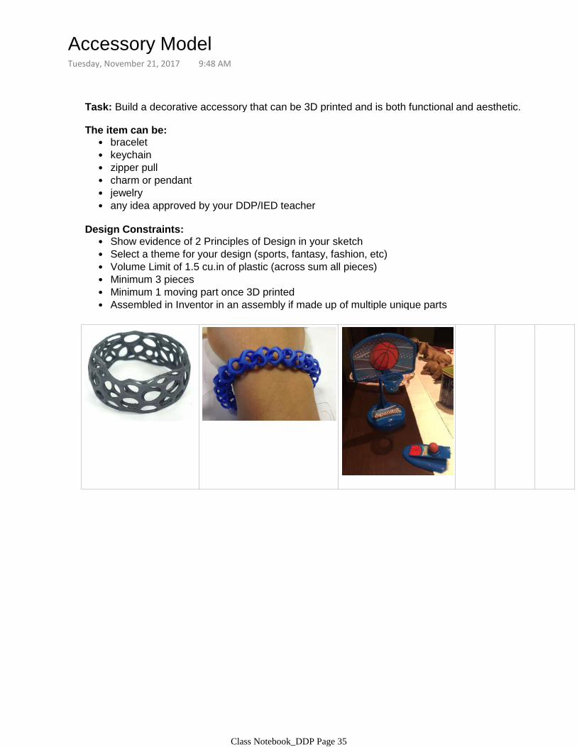
Task: Build a decorative accessory that can be 3D printed and is both functional and aesthetic.
bracelet•keychain•zipper pull•charm or pendant•jewelry•any idea approved by your DDP/IED teacher•
The item can be:
Show evidence of 2 Principles of Design in your sketch•Select a theme for your design (sports, fantasy, fashion, etc)•Volume Limit of 1.5 cu.in of plastic (across sum all pieces)•Minimum 3 pieces•Minimum 1 moving part once 3D printed•Assembled in Inventor in an assembly if made up of multiple unique parts•
Design Constraints:
Accessory ModelTuesday, November 21, 2017 9:48 AM
Class Notebook_DDP Page 35
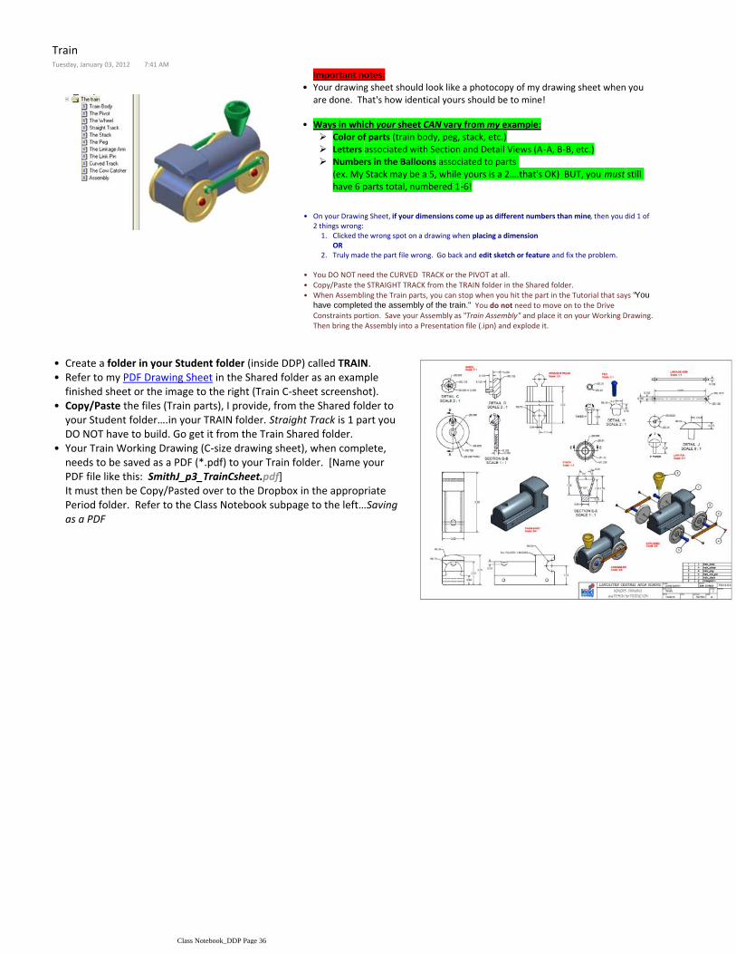
Create a folder in your Student folder (inside DDP) called TRAIN.•Refer to my PDF Drawing Sheet in the Shared folder as an example finished sheet or the image to the right (Train C-sheet screenshot).
•
Copy/Paste the files (Train parts), I provide, from the Shared folder to your Student folder….in your TRAIN folder. Straight Track is 1 part you DO NOT have to build. Go get it from the Train Shared folder.
•
Your Train Working Drawing (C-size drawing sheet), when complete, needs to be saved as a PDF (*.pdf) to your Train folder. [Name your PDF file like this: SmithJ_p3_TrainCsheet.pdf]It must then be Copy/Pasted over to the Dropbox in the appropriate Period folder. Refer to the Class Notebook subpage to the left…Saving as a PDF
•
Important notes:Your drawing sheet should look like a photocopy of my drawing sheet when you are done. That's how identical yours should be to mine!
•
Color of parts (train body, peg, stack, etc.)
Letters associated with Section and Detail Views (A-A, B-B, etc.)
Numbers in the Balloons associated to parts (ex. My Stack may be a 5, while yours is a 2….that's OK) BUT, you must still have 6 parts total, numbered 1-6!
Ways in which your sheet CAN vary from my example:•
Clicked the wrong spot on a drawing when placing a dimensionOR
1.
Truly made the part file wrong. Go back and edit sketch or feature and fix the problem.2.
On your Drawing Sheet, if your dimensions come up as different numbers than mine, then you did 1 of 2 things wrong:
•
You DO NOT need the CURVED TRACK or the PIVOT at all.•
Copy/Paste the STRAIGHT TRACK from the TRAIN folder in the Shared folder.•
When Assembling the Train parts, you can stop when you hit the part in the Tutorial that says "You
have completed the assembly of the train." You do not need to move on to the Drive Constraints portion. Save your Assembly as "Train Assembly" and place it on your Working Drawing. Then bring the Assembly into a Presentation file (.ipn) and explode it.
•
TrainTuesday, January 03, 2012 7:41 AM
Class Notebook_DDP Page 36

EXPORT your C-size drawing sheet as a PDF1.File > Export > PDF
Name the file like this (SmithJ_p3_TrainCsheet)Lastname Firstinitial_period_TrainCsheet
2.
And direct it into your Train folder on the R:/ drive
Through Windows (My Computer), do a COPY/PASTE of your Train sheet working drawing PDF from your Student folder (3.a.) into the appropriate DROPBOX folder (3.b.).a.
3.
Saving as a PDF (and placing it in the Dropbox)Wednesday, January 05, 2011 3:47 PM
Class Notebook_DDP Page 37

a.
b.
Check with Mr.Streit to confirm it is in the Dropbox. He will NOT hunt you down for it. He will ONLY look for the PDF in the appropriate Dropbox folder!! If it's not there, you'll receive no grade.
4.
Class Notebook_DDP Page 38
In teams of 2, you will research, organize, and present on an engineering discipline.
Check the Shared folder for samples (good and bad), the grade rubric, and other materials.
Engineering Presentations
Your team is required to select and research a discipline in the Engineering field. After researching, your team will present the information to your classmates using Power Point.
Read Wikipedia article on engineering
(In the search box, type Engineering and then do it again for Outline of Engineering)
Aerospace
Chemical
Petroleum
Pharmaceutical
Agricultural
Civil
Structural
Electrical
Computer
Mechanical
Automotive
Ergonomic
Industrial
Bioengineering
Biomedical
Engineering Disciplineso
Engineering presentations must cover:
Career description
Duties & Responsibilities (day to day tasks)
Working Conditions (positive & negative)
Employment outlook (hiring or firing projection)
Three nearest schools who offer the program
(Name of school, city/town, & miles from Lancaster)Earnings (Beginner vs. Experienced)
Why would you (or would you not) choose this career?
Sources of Information
For each field chosen (major and minor):
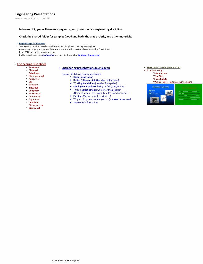
Know what’s in your presentation!
* Introduction* Text Size* Short Bullets* Visuals (aids) – pictures/charts/graphs
Slideshow setup
Engineering PresentationsMonday, January 30, 2012 8:43 AM
Class Notebook_DDP Page 39

Dual Purpose Table
Grade based on effort , participation, and submission of a solution. (DDP Tech will get a grade for submission)
45" x 87" x 1.75" 22" radius at corners5" bumper5" track
Need:1 table to serve 2 purposes- poker table and puzzle and game table but self-storing
Fold away small and be storable OR flip over and be dual sided dual purpose-
Be strong and be smooth on top...no holes, pegs, hinges, etc. (puzzles, board games)-
Must:
Damage either surface/table while be stored.-
Attach to legs so table is stable-
Must Not:
Notes: Plywood comes in 4'x8' sheets
Constraints:Budget - under $100Materials - wood or metal or other affordable goodsWeight - able to be moved by 1 or 2 peopleAesthetics - must look nice when doneFunctionality- must work as a game/conference/dining table (puzzles, board games, dining)
Engineering Design ChallengeFriday, January 29, 2016 1:49 PM
Class Notebook_DDP Page 40

Metal BlocksSketch, measure, dimension, and re-build 2 metal blocks.
Title: METAL BLOCK 1Scale: FULL or 1:1
2nd metal block - Repeat the process again.
Title: METAL BLOCK 2Scale: FULL or 1:1
Print to the HP4015 printer, for both sheets.
LEGO Block #1
Fill out the Visual/ Functional/ Structural Chart based on the LEGO.
Sketch, measure, dimension, and re-build a LEGO block.
-----------------------------------------------------------------------LEGO parametric modeling
Parametric Modeling: A CAD modeling method thatuses parameters to define the size and geometry offeatures and to create relationships between features.Changing a parameter value updates all related features of the model at once.
Parameter "Comments"DepthWidthHeightHt. Taper AngleWall thicknessPeg DiameterPeg LocationPeg LocationPeg HeightPeg height taper angle
Automoblox
VEHICLES:
Model Color Photo
X9-X Sport Utility Purple
S9 Sedan Dark Blue
T9 Pick-up Green
C9-S Sports Car Orange
M9 Sportvan Light Blue
Items due for this project:1. V, S, F chart (Product Analysis chart)2. Automoblox Assembled/Exploded Working Drawing
File PRINT1.
Pick 165 copier2.
Click PROPERTIES3.
Select LEDGER 11”x17” for Paper Size4.
Make sure it’s on LANDSCAPE5.
Hit OK to print it.6.
Reverse EngineeringTuesday, February 07, 2012 7:56 AM
Class Notebook_DDP Page 41
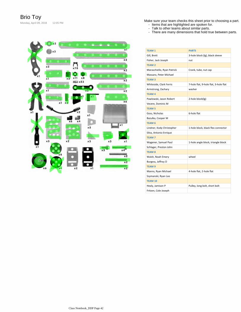
Items that are highlighted are spoken for.-Talk to other teams about similar parts.-There are many dimensions that hold true between parts.-
Make sure your team checks this sheet prior to choosing a part.
TEAM 1 PARTS
Gill, Brett 3-hole block (lg), black sleeve
Fisher, Jack Joseph nut
TEAM 2
Maraschiello, Ryan Patrick Crank, tube, nut cap
Massaro, Peter Michael
TEAM 3
Whiteside, Clark Ferris 7-hole flat, 9-hole flat, 3-hole flat
Armstrong, Zachary washer
TEAM 4
Pawlowski, Jason Robert 2-hole block(lg)
Vecere, Dominic M
TEAM 5
Goss, Nicholas 6-hole flat
Bazulka, Cooper M
TEAM 6
Lindner, Kody Christopher 1-hole block, black flex connector
Silva, Antonio Enrique
TEAM 7
Wagener, Samuel Paul 1-hole angle block, triangle block
Schlager, Preston John
TEAM 8
Walsh, Noah Emery wheel
Burgess, Jeffrey D
TEAM 9
Manns, Ryan Michael 4-hole flat, 2-hole flat
Szymanski, Ryan Lee
TEAM 10
Healy, Jamison P Pulley, long bolt, short bolt
Fritzen, Cole Joseph
Brio ToyMonday, April 09, 2018 12:05 PM
Class Notebook_DDP Page 42

Hydraulic Arm
From backyard log splitters to the huge machines you see on construction sites, hydraulic equipment is amazing in its strength and agility! On any construction site you see hydraulically operated machinery in the form of bulldozers, backhoes, shovels, loaders, fork lifts and cranes.
Hydraulics operate the control surfaces on any large airplane. You see hydraulics at car service centers lifting the cars so that mechanics can work underneath them, and many elevators are hydraulically operated using the same technique. Even the brakes in your car use hydraulics!
In this article, you will learn about the basic principles that hydraulic systems use to do their work, and then we'll examine several different pieces of hydraulic machinery found on a construction site. You will be amazed at the power and versatility available with hydraulics.
Pasted from <http://science.howstuffworks.com/transport/engines-equipment/hydraulic.htm>
Hydraulic: 1. the physical science and technology of the static
and dynamic behavior of fluids 2. the action of forces on bodiesRobot: a mechanical device for performing a task which might otherwise be done by a human.Pascal's Law: a change in pressure applied to an enclosed
incompressible fluid is transmitted undiminished to every portion of the fluid to the walls of its container.In other words, an incompressible fluid transmits pressure.Boyle's Law: a fixed amount of gas at a fixed temperature, the
pressure and the volume are inversely proportional.
Vocabulary:
Hydraulic Arm
Objective: Research, develop, design, build and test a hydraulic robotic arm.
7 week timeframe•Under $20 per robot•
6 syringes○
5 syringe clips○
8" x 5.5" x 3/4" wooden base○
24" x 11/16" x 1/4" wooden arm○
3/4" dia. X 7" wooden dowel○
2.0 cubic inches (max.) of ABS plastic - layered from the 3D printer○
5" x 3/4" section of PVC pipe - notch at 3/4" in from end○
Screw eyes○
Machine screws○
Machine nuts○
3' of clear hose (hydraulic fluid line)○
20 sq. in. of foam board○
Materials•
Parameters/Constraints:
Gather pictures into a Word document (named Research)
Research and Investigation of gripper types1.
Multiple thumbnail sketch solutions to resolve the problem
Move to a quality Annotated sketch, once you pick our best one.
Thumbnail Sketches Annotated Sketch
Sketch possible gripper solutions2.
Create it as one single part file…… then…..
□
Develop the separate parts needed for your gripper
Design your gripper in Inventor3.
iProperties > Physical > ABS plastic > Check volume (2.0 cu.in. max)
Check volume of gripper parts - Not to exceed 2.0 cu.in.4.
Make a rough version (out of foam board) of your potential gripper
Test it on the sample robot in front
Foam board mock-up Foam board mock -up
Foam board mock-up of gripper5.
BASE Width 8"
Hole location: 2.75" and 3.00"
Height 3/4" Depth 5.5"
Following the given dimensions and specifications, build (in Inventor) the 3 wood parts [base, dowel, and arm]
Create 3D models of wood items based off of my materials list and/or drawings6.
IndividuallySTEPS:
TECHNICAL REPORT documentation:
Hydraulic ArmFriday, March 15, 2013 9:53 AM
Class Notebook_DDP Page 43

Hole location: 2.75" and 3.00"
Hole diameter: 1.00"Hole depth: .25"
5.5"
DOWEL Diameter 3/4"
Flat notch: 1.5" down
Height 7"
ARM Width 24"
Holes at 7" and 3/8"0.2" diameter
Height 11/16"
Depth 1/4"
□
Following the directions given in class (or referring to the Design Briefs PowerPoint), develop a Design Brief for the Hydraulic Robotic Arm project
Develop a Design Brief7.
Decision Matrix1.Develop/decide on a team gripper2.
Create a foam board mock-up if new team design3.
Submit team STL files of gripper pieces4.Reverse engineer syringe- as a group5.
Share syringe across group6.
Drill pivot point at 7" down arm - otherwise you can't reach stations!!1.
Gripper connection must be within 1" of arm's end2.
Drill holes in wooden parts7.
Assemble robot (in reality)8.
Groups
Assemble the robot in Inventor- Use YOUR gripper in your assembly1.Create necessary drawings2.
Sketches (thumbnail and annotated)1)Design Brief2)
Decision Matrix3)
Bill of Materials and ABS Plastic Volume4)Assembled View Working Drawing 5)
Detail Drawings (of pivot and gripper)6)
Put together a Technical Report3.
Test skills with robot4.
Individually
Class Notebook_DDP Page 44
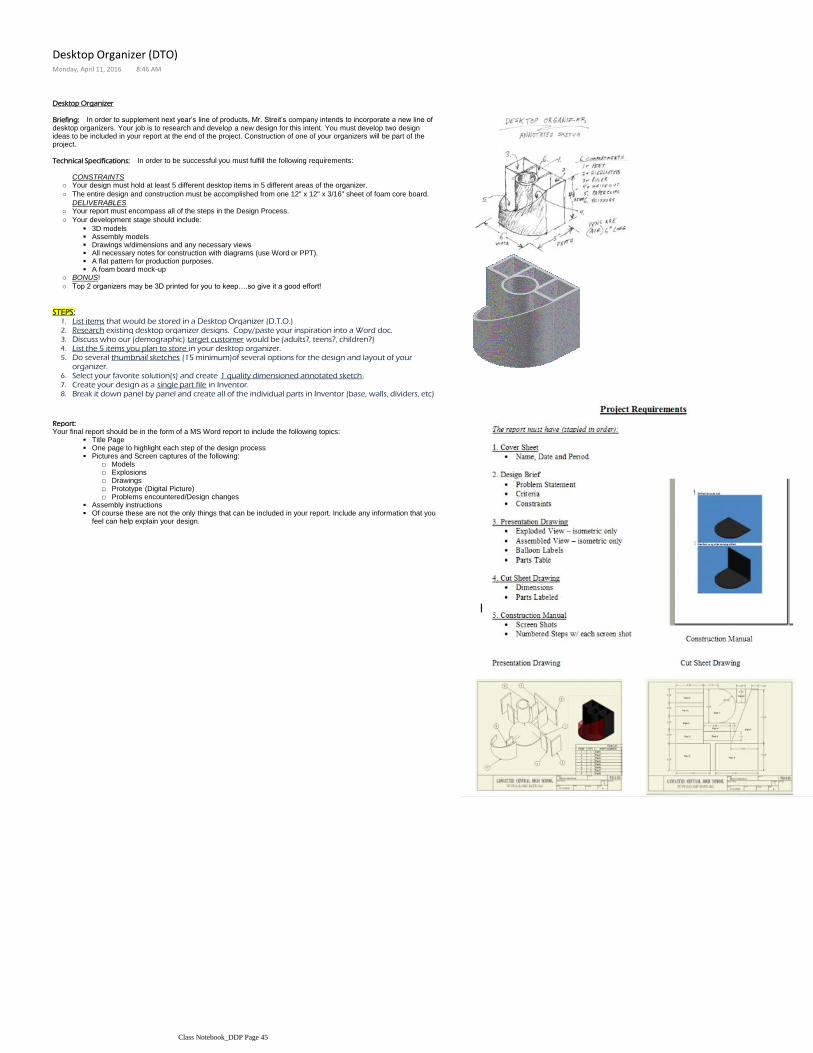
Desktop Organizer
Briefing: In order to supplement next year’s line of products, Mr. Streit’s company intends to incorporate a new line of desktop organizers. Your job is to research and develop a new design for this intent. You must develop two design ideas to be included in your report at the end of the project. Construction of one of your organizers will be part of the project.
Technical Specifications: In order to be successful you must fulfill the following requirements:
CONSTRAINTSYour design must hold at least 5 different desktop items in 5 different areas of the organizer.○
The entire design and construction must be accomplished from one 12" x 12" x 3/16" sheet of foam core board.○
DELIVERABLESYour report must encompass all of the steps in the Design Process. ○
3D models
Assembly models
Drawings w/dimensions and any necessary views
All necessary notes for construction with diagrams (use Word or PPT).
A flat pattern for production purposes.
A foam board mock-up
Your development stage should include:○
BONUS!○
Top 2 organizers may be 3D printed for you to keep….so give it a good effort!○
List items that would be stored in a Desktop Organizer (D.T.O.)1.
Research existing desktop organizer designs. Copy/paste your inspiration into a Word doc.2.
Discuss who our (demographic) target customer would be (adults?, teens?, children?)3.
List the 5 items you plan to store in your desktop organizer.4.
Do several thumbnail sketches (15 minimum)of several options for the design and layout of your organizer.
5.
Select your favorite solution(s) and create 1 quality dimensioned annotated sketch.6.
Create your design as a single part file in Inventor.7.
Break it down panel by panel and create all of the individual parts in Inventor (base, walls, dividers, etc)8.
STEPS:
Report:
Title Page
One page to highlight each step of the design process
Models□Explosions□Drawings□Prototype (Digital Picture)□Problems encountered/Design changes□
Pictures and Screen captures of the following:
Assembly instructions
Of course these are not the only things that can be included in your report. Include any information that you feel can help explain your design.
Your final report should be in the form of a MS Word report to include the following topics:
Desktop Organizer (DTO)Monday, April 11, 2016 8:46 AM
Class Notebook_DDP Page 45