Juniper Networks Junos Space Network Management Platform ...

Copyright © 2013, Juniper Networks, Inc.
____________________________________________________________________________________________
Junos DDoS Secure GUI User Guide
Published: 2013-07-26
Juniper Networks, Inc.
1194 North Mathilda Avenue
Sunnyvale, California 94089
USA
408-745-2000
www.juniper.net

Copyright © 2013, Juniper Networks, Inc ii
This product includes the Envoy SNMP Engine, developed by Epilogue Technology, an Integrated Systems Company.Copyright©1986-1997,Epilogue Technology Corporation. All rights reserved. This program and its documentation were developed at private expense, and no part of them is in the public domain.
This product includes FreeBSD software developed by the University of California, Berkeley, and its contributors. All of the documentation and software included in the 4.4BSD and 4.4BSD-Lite Releases is copyrighted by the Regents of the University of California. Copyright © 1979,1980,1983,1986,1988,1989,1991,1992,1993,1994.The Regents of the University of California. All rights reserved.
GateD software copyright © 1995, the Regents of the University. All rights reserved. Gate Daemon was originated and developed through release 3.0 by Cornell University and its collaborators. Gated is based on Kirton’sEGP, UC Berkeley’s routing daemon (routed), and DCN’s HELLO routing protocol. Development of Gated has been supported in part by the National Science Foundation. Portions of the GateD software copyright © 1988, Regents of the University of California. All rights reserved. Portions of the GateD software copyright © 1991, D. L. S. Associates. This product includes software developed by Maker Communications, Inc., copyright © 1996,1997, Maker Communications, Inc.
Juniper Networks, Junos, Steel-Belted Radius, NetScreen, and ScreenOS are registered trademarks of Juniper Networks, Inc. in the United States and other countries. The Juniper Networks Logo, the Junos logo, and JunosE are trademarks of Juniper Networks, Inc. All other trademarks, service marks, registered trademarks, or registered service marks are the property of the respective owners.
Juniper Networks assumes no responsibility for any inaccuracies in this document .Juniper Networks reserves the right to change, modify, transfer, or otherwise revise this publication without notice.
DATA LICENSE (GeoLite Country and GeoLite City databases) Copyright (c) 2008 MaxMind, Inc. All Rights Reserved. All advertising materials and documentation mentioning features or use of this database must display the following acknowledgment: "This product includes GeoLite data created by MaxMind, available from http://maxmind.com/" Redistribution and use with or without modification, are permitted provided that the following conditions are met: 1. Redistributions must retain the above copyright notice, this list of conditions and the following disclaimer in the documentation and/or other materials provided with the distribution. 2. All advertising materials and documentation mentioning features or use of this database must display the following acknowledgement: "This product includes GeoLite data created by MaxMind, available from http://maxmind.com/" 3. "MaxMind" may not be used to endorse or promote products derived from this database without specific prior written permission. THIS DATABASE IS PROVIDED BY MAXMIND, INC ``AS IS'' AND ANY EXPRESS OR IMPLIED WARRANTIES, INCLUDING, BUT NOT LIMITED TO, THE IMPLIED WARRANTIES OF MERCHANTABILITY AND FITNESS FOR A PARTICULAR PURPOSE ARE DISCLAIMED. IN NO EVENT SHALL MAXMIND BE LIABLE FOR ANY DIRECT, INDIRECT, INCIDENTAL, SPECIAL, EXEMPLARY, OR CONSEQUENTIAL DAMAGES (INCLUDING, BUT NOT LIMITED TO, PROCUREMENT OF SUBSTITUTE GOODS OR SERVICES; LOSS OF USE, DATA, OR PROFITS; OR BUSINESS INTERRUPTION) HOWEVER CAUSED AND ON ANY THEORY OF LIABILITY, WHETHER IN CONTRACT, STRICT LIABILITY, OR TORT (INCLUDING NEGLIGENCE OR OTHERWISE) ARISING IN ANY WAY OUT OF THE USE OF THIS DATABASE, EVEN IF ADVISED OF THE POSSIBILITY OF SUCH DAMAGE.
Some parts of this software distribution are derived from the APNIC, ARIN and RIPE databases (copyright details below). The author of this module makes no claims of ownership on those parts. APNIC conditions of use: The files are freely available for download and use on the condition that APNIC will not be held responsible for any loss or damage arising from the application of the information contained in these reports. APNIC endeavours to the best of its ability to ensure the accuracy of these reports; however, APNIC makes no guarantee in this regard. In particular, it should be noted that these reports seek to indicate the country where resources were first allocated or assigned. It is not intended that these reports be considered as an authoritative statement of the location in which any specific resource may currently be in use. ARIN database copyright: Copyright (c) American Registry for Internet Numbers. All rights reserved. RIPE database copyright:
The information in the RIPE Database is available to the public for agreed Internet operation purposes, but is under copyright. The copyright statement is: "Except for agreed Internet operational purposes, no part of this publication may be reproduced, stored in a retrieval system, or transmitted, in any form or by any means, electronic, mechanical, recording, or otherwise, without prior permission of the RIPE NCC on behalf of the copyright holders. Any use of this material to target advertising or similar activities is explicitly forbidden and may be prosecuted. The RIPE NCC requests to be notified of any such activities or suspicions thereof. Products made or sold by Juniper Networks or components thereof might be covered by one or more of the following patents that are owned by or licensed to Juniper Networks: U.S. Patent Nos.5,473,599,5,905,725,5,909,440,6,192,051,6,333,650,6,359,479,6,406,312, 6,429,706,6,459,579,6,493,347,6,538,518,6,538,899,6,552,918,6,567,902,6,578,186, and6,590,785.
Copyright © 2013 Juniper Networks, Inc. All rights reserved. Printed in USA.
Junos DDoS Secure GUI User Guide
Revision History
July 2013; Revision 2

Copyright © 2013, Juniper Networks, Inc iii
The information in this document is current as of the date listed in the revision history.
SOFTWARE LICENSE
The terms and conditions for using this software are described in the software license contained in the acknowledgment to your purchase order or, to the extent applicable, to any reseller agreement or end-user purchase agreement executed between you and Juniper Networks. By using this software, you indicate that you understand and agree to be bound by those terms and conditions.
Generally speaking, the software license restricts the manner in which you are permitted to use the software and may contain prohibitions against certain uses. The software license may state conditions under which the license is automatically terminated. You should consult the license for further details.
For complete product documentation, please see the Juniper Networks Website at www.juniper.net/techpubs.
END USER LICENSE AGREEMENT
The Juniper Networks product that is the subject of this technical documentation consists of (or is intended for use with) Juniper Networks software. Use of such software is subject to the terms and conditions of the End User License Agreement (“EULA”) posted at http://www.juniper.net/support/eula.html. By downloading, installing or using such software, you agree to the terms and conditions of that EULA

Copyright © 2013, Juniper Networks, Inc iv
Table of Contents
Junos DDoS Secure GUI User Guide ............................................................................................... i
About This Guide ........................................................................................................................... viii
Objective .................................................................................................................................. viii
Audience .................................................................................................................................. viii
DDoS Documentation and Release Notes .............................................................................. viii
Obtaining Documentation ........................................................................................................ viii
Documentation Feedback........................................................................................................ viii
Requesting Technical Support ................................................................................................. ix
Self-Help Online Tools and Resources .................................................................................... ix
Opening a Case with JTAC ...................................................................................................... ix
Feature Overview ............................................................................................................................. 1
Getting Started ................................................................................................................................. 4
Connecting DDoS Secure Appliance to Your Network ....................................................... 4
Interface Conventions ......................................................................................................... 5
Defending versus Logging .................................................................................................. 5
Accessing your Secure DDoS Appliance ............................................................................ 5
Imaging your DDoS Secure Appliance ............................................................................... 6
Re-Imaging your DDoS Secure Appliance after Hardware Replacement .......................... 6
Configuring Basic Settings .................................................................................................. 6
Configuring the Management Interface .............................................................................. 7
Configuring Integrated Lights Out (ILO) .............................................................................. 8
Connecting to the DDoS Secure Appliance ........................................................................ 8
First Boot ........................................................................................................................... 10
Overview Page .................................................................................................................. 12
DDoS Secure Appliance Web Interface Screen Layout ................................................... 13
Page Specific Action ......................................................................................................... 14
View Filters ........................................................................................................................ 14
Other View Filters.............................................................................................................. 15
Select Viewing Option ....................................................................................................... 15
Logout ............................................................................................................................... 15
Screen Interaction ................................................................................................................... 16
Expanding Central Pane Area .......................................................................................... 16
Arranging Table Ordering ................................................................................................. 16
Arranging Column Ordering .............................................................................................. 17
Sorting Data and Add-Remove Columns .......................................................................... 17
Action Cells ....................................................................................................................... 18
IP / AS# / Location Details ................................................................................................ 18

Copyright © 2013, Juniper Networks, Inc v
Graphs .............................................................................................................................. 19
Configuration and Logs .................................................................................................................. 21
Configuration Overview ........................................................................................................... 21
Access Control ........................................................................................................................ 22
User Access ...................................................................................................................... 22
Configure Interfaces ................................................................................................................ 24
Common Interface Displayed Information ........................................................................ 26
Internet Interface Definition ............................................................................................... 26
Configure DDoS Secure .......................................................................................................... 28
Internet Gateways (based on MAC Addresses) ............................................................... 30
Adding Internet MAC Address .......................................................................................... 31
Configuring Appliance ....................................................................................................... 31
Configure Sharing Information .......................................................................................... 39
Configuring Protected Gateways (based on MAC Address) ............................................ 40
New Protected MAC Address ........................................................................................... 41
Pseudo Layer 3 Configuration .......................................................................................... 42
DDoS Secure Portal Configuration .......................................................................................... 43
Existing Portals ................................................................................................................. 47
Bandwidth and Port Filters ................................................................................................ 47
Configure Filter Aggregations ........................................................................................... 50
Configure Protected IPs .................................................................................................... 50
Defined Protected IPs ....................................................................................................... 54
Configuring Date and Time...................................................................................................... 55
Configuring Logging ................................................................................................................ 56
Portals ............................................................................................................................... 56
SNMP ................................................................................................................................ 57
Syslog Server .................................................................................................................... 57
Webtrends Server ............................................................................................................. 59
Mail Server ........................................................................................................................ 60
Proxy Server ..................................................................................................................... 62
GeoIP Database(s) ........................................................................................................... 63
Incident Create Threshold ................................................................................................. 63
Incident Alert Threshold .................................................................................................... 64
Incident View Threshold .................................................................................................... 65
Incident Peak Values ........................................................................................................ 66
Worst Offenders Logging Threshold ................................................................................. 66
General Logging................................................................................................................ 67
Debug Options .................................................................................................................. 67

Copyright © 2013, Juniper Networks, Inc vi
Configuration File .................................................................................................................... 68
Statistics Reports ..................................................................................................................... 69
General Logs ........................................................................................................................... 71
Incident Logs ........................................................................................................................... 73
Display Incident Details ..................................................................................................... 74
Worst Offenders Log File ......................................................................................................... 74
Upgrades ................................................................................................................................. 75
Packet Capture ........................................................................................................................ 77
Packet Capture Recording Termination ............................................................................ 79
Packet Capture Display .................................................................................................... 80
Packet Capture Save Off the DDoS Secure Appliance .................................................... 81
Shutdown DDoS Secure Appliance .................................................................................. 83
Statistical Displays ......................................................................................................................... 85
Summary Dashboard ............................................................................................................... 85
Status Information ................................................................................................................... 86
Protected Information .............................................................................................................. 90
Live Incidents ........................................................................................................................... 92
Worst Offenders ...................................................................................................................... 93
Temporarily Black Listed ......................................................................................................... 96
IP Tracked Information ............................................................................................................ 97
Country Usage Information...................................................................................................... 99
TCP Information .................................................................................................................... 100
UDP Information .................................................................................................................... 102
ICMP Information ................................................................................................................... 103
Other IP Information .............................................................................................................. 105
Fragment Information ............................................................................................................ 106
URL Information .................................................................................................................... 107
DNS Information .................................................................................................................... 109
SIP Information ...................................................................................................................... 110
Bandwidth Information ........................................................................................................... 111
ReRoute Information ............................................................................................................. 112
MAC Information .................................................................................................................... 113
Miscellaneous Information ..................................................................................................... 115
DDoS Secure Appliance Tables ..................................................................................... 117
Defense Information ..................................................................................................................... 120
Operational Mode............................................................................................................ 120
Failover States ................................................................................................................ 121
Failover Information ........................................................................................................ 122

Copyright © 2013, Juniper Networks, Inc vii
State Synchronization Information .................................................................................. 122
Record / Replay State ..................................................................................................... 122
Transition States ............................................................................................................. 122
Appliance or Protected IP Information ............................................................................ 123
Defense Status................................................................................................................ 124
Additional Status ............................................................................................................. 126
DDoS Secure Appliance TCP States ........................................................................................... 130
ICMP Types ................................................................................................................................. 132
Incident (attack) Types ................................................................................................................. 134
Letter Country Codes ................................................................................................................... 141
Sorted by Code ............................................................................................................... 141
Sorted by Country ........................................................................................................... 143
Panel and Connector Locations ................................................................................................... 145
DDoS Secure1200-Failsafe Panels ....................................................................................... 145
Troubleshooting ........................................................................................................................... 147
GUI Branding ............................................................................................................................... 148
Login Page ............................................................................................................................ 148
Images / CSS Files ................................................................................................................ 148
Updating Customized Files.................................................................................................... 148
Removing Customized Files .................................................................................................. 148

Copyright © 2013, Juniper Networks, Inc viii
ABOUT THIS GUIDE
Objective
The guide provides the set-up and configuration information for the Junos DDoS appliance
from an overall management perspective. The DDoS appliance supports the notion of sub
Virtual DDoS appliances where users (clients) can manage their own set of allocated IP
addresses.
Audience
This guide is designed for network administrators who are installing and maintaining a
Junos DDoS Secure appliance. To use this guide, you need a broad understanding of
networks in general and the Internet in particular, networking principles, network
configuration and virtualization. Any detailed discussion of these concepts is beyond the
scope of this guide.
DDoS Documentation and Release Notes
For a list of related DDoS Secure appliance documentation, see is http://www.juniper.net/techpubs/en_US/release-independent/ddos/information-
products/pathway-pages/product/index.html
If the information in the latest Junos DDoS Secure appliance Release Notes differs from
the information in the documentation, follow the Junos DDoS Secure appliance Release
Notes.
Obtaining Documentation
To obtain the most current version of all Juniper Networks technical documentation, see
the products documentation page on the Juniper Networks website at
http://www.juniper.net/techpubs.
To order printed copies of this guide and other Juniper Networks technical documents, or to
order a documentation CD, which contains this guide, contact your sales representative.
Documentation Feedback
We encourage you to provide feedback, comments, and suggestions so that we can
improve the documentation. You can send your comments to techpubs-
[email protected], or fill out the documentation feedback format
http://www.juniper.net/techpubs/docbug/docbugreport.html. If you are using e-mail, be sure
to include the following information with your comments:
Document name
Document part number
Page number
Software release version

Copyright © 2013, Juniper Networks, Inc ix
Requesting Technical Support
Technical product support is available through the Juniper Networks Technical Assistance
Center (JTAC). If you are a customer with an active J-Care or JNASC support contract, or
are under warranty, and need post sales technical support, you can access our tools and
resources online or open a case with JTAC.
JTAC policies—For a complete understanding of our JTAC procedures and
policies, review the JTAC User Guide located at
http://www.juniper.net/us/en/local/pdf/resource-guides/7100059-en.pdf.
Product warranties—For product warranty information, visit
http://www.juniper.net/support/warranty/.
JTAC Hours of Operation —The JTAC centers have resources available 24 hours
a day, 7 days a week, 365 days a year.
Self-Help Online Tools and Resources
For quick and easy problem resolution, Juniper Networks has designed an online self-
service portal called the Customer Support Center (CSC) that provides you with the
following features:
Find CSC offerings: http://www.juniper.net/customers/support/
Find product documentation: http://www.juniper.net/techpubs/
Find solutions and answer questions using our Knowledge Base:
http://kb.juniper.net/
Download the latest versions of software and review release notes:
http://www.juniper.net/customers/csc/software/
Search technical bulletins for relevant hardware and software notifications:
https://www.juniper.net/alerts/
Join and participate in the Juniper Networks Community Forum
http://www.juniper.net/company/communities/
Open a case online in the CSC Case Management tool: http://www.juniper.net/cm/
To verify service entitlement by product serial number, use our Serial Number Entitlement
(SNE) Tool: https://tools.juniper.net/SerialNumberEntitlementSearch/
Opening a Case with JTAC
You can open a case with JTAC on the Web or by telephone.
Use the Case Management tool in the CSC at http://www.juniper.net/cm/
Call 1-888-314-JTAC (1-888-314-5822 toll-free in the USA, Canada, and Mexico).
For international or direct-dial options in countries without toll-free numbers, visit us at
http://www.juniper.net/support/requesting-support.html

Copyright © 2013, Juniper Networks, Inc x

Copyright © 2013, Juniper Networks, Inc 1
CHAPTER 1
FEATURE OVERVIEW
Junos DDoS Secure appliance is a fully automatic DDoS protection system used typically
for websites and web-connected e-commerce sites. DDoS Secure protects all TCP/IP
protocols. An appliance can be real hardware, or can be a virtual instance (such as
VMware).
Figure 1: Traffic Flow Through Junos DDoS Secure Appliance
Figure 1 illustrates how normal Internet traffic flows through the Junos DDoS Secure
appliance, while the software analyzes the type, origin, flow, data rate, sequencing, style
and protocol being utilized by all inbound and outbound traffic. The analysis is heuristic in
nature and adjusts over time but is applied in real time, with virtually no latency.
Figure 2: Attack Traffic Flow Through the Junos DDoS Secure Appliance

Copyright © 2013, Juniper Networks, Inc 2
Figure 2 indicated how sophisticated data analysis techniques within DDoS Secure
appliance detect that an attack is underway, causing the appliance to take defensive
measures.
Figure 3: Traffic Analysis Block Diagram
1. Validates data packet
Validates against defined filters Validates packet against RFCs Validates packet sequencing TCP Connection state
3. Behaviour is recorded
Supports up to 16M profiles Profiles aged on least used basis
4. Calculates CHARM Threshold
Responsiveness of Resource
2. Calculates CHARM value for data packet
References IP behaviour table Function of time and historical behavior Better behaved = better CHARM
5. Allow or Drop
CHARM Threshold CHARM Value

Copyright © 2013, Juniper Networks, Inc 3
Figure 3 illustrates how all inbound traffic that has been determined to be normal (good
Charm score) will pass through the appliance unchanged. All inbound traffic that has been
determined as malicious (bad Charm score) will be discarded if the protected resource
cannot handle the load. The appliance has no IP addresses to configure on its Internet
traffic interfaces and may be installed without change to the network configuration of any
existing equipment. One IP address is required for the secure control connection to the
management PC. The management PC (not provided) requires a modern browser
supporting HTML frames, JavaScript and the https protocol, or alternatively a SSH client,
and is used to initially configure the appliance and then to report on the traffic statistics.
During an attack the appliance will use its built-in heuristic analysis to identify the most
likely attackers within a few microseconds of an attack beginning. The longer the appliance
has been analyzing traffic, the better the heuristic analysis. Attacks are tracked on a per
incident basis for easy reporting and analysis.
It is possible to specify blocks of IP addresses (networks and/or single IP addresses– in
what are known as Portals, which can be managed separately by designated users. This
gives the ability for customers, clients or Business Groups to manage what DDoS Secure
appliance does for their Portal. Any user having full managerial access can override these
portal configurations. The master portal is known as webscreen.

Copyright © 2013, Juniper Networks, Inc 4
CHAPTER 2
GETTING STARTED
This chapter helps you to connect your DDoS Secure appliance to the network.
Connecting DDoS Secure Appliance to Your Network
Figure 4: DDoS Secure Standalone Appliance
Figure 4 illustrates the setup for a single standalone DDoS Secure appliance.
Figure 5: DDoS Secure Appliance Network Connection in a HA cluster
Figure 5 illustrates how DDoS Secure appliances are set up in an Active/Standby HA
Cluster.

Copyright © 2013, Juniper Networks, Inc 5
Determine the appropriate I/O connectors for your DDoS Secure appliance [DDoS
Secure1200-Failsafe Panels], and cable accordingly. It is not necessary to run the
appliance with a monitor / keyboard, but it is useful for hardware fault diagnosis and it can
be used for access via the Command Line Interface (CLI).
Interface Conventions
Interfaces are named as following:
I-I/F—Internet Interface
P-I/F—Protected Interface
M-I/F—Management PC Interface
D-I/F—Data Share Interface (Optional)
Crossover cables may be required when plugging directly into a server, router or similar
gateway device. A standard cable should be used for connecting to a switch or hub. The
same switch or hub must not be used for connecting to both I-I/F and P-I/F, unless there is
VLAN separation.
The Management PC can be directly connected to the appliance with a crossover cable or
through a network with a hub/switch and optionally via a router (after the correct default
gateway has been set on the appliance). Depending on your security policy, you may want
to connect the M-I/F to the Internet or Protected networks.
Defending versus Logging
The DDoS Secure appliance supports different components in one of two operational
modes. They are:
Defending—If the DDoS Secure appliance detects a undesirable packet it logs the fact and the packet is dropped.
Logging—If the DDoS Secure appliance detects a undesirable packet it logs the fact, but still let the packet through.
Examples of different components are:
Overall Operation—Logging or Defending
Portal Operation—Logging or Defending
Protected IP Operation—Logging or Defending
White-Listed Client IP—Logging
Black-Listed Client IP—Defending
If an activity comprises of using components that contain a mixture of Defending and
Logging, the resultant operational mode will be Logging. Thus for a black-listed client IP
and overall operation of Defending and portal operation of Logging and protected IP
operation of Defending, the client IP will not actually get dropped.
Accessing your Secure DDoS Appliance
The DDoS Secure appliance can be accessed via one of four methods. They are:
Keyboard or monitor— Used for Command Line Interface (CLI) access, or to configure the Management Interface IP address.
Serial interface—Used for CLI access, or to configure the Management Interface IP address.
SSH connection—Used for secure remote CLI access only.

Copyright © 2013, Juniper Networks, Inc 6
Secure Web interface—Used for secure web interface.
Imaging your DDoS Secure Appliance
Your DDoS Secure appliance is shipped pre-imaged with the DDoS Secure appliance
software. If your appliance is not shipped with the software, then the appliance must be re-
imaged from a DDoS Secure appliance ISO image (burnt to a CDROM) and the appliance
must be upgraded to the latest version of the software. See the Junos DDoS Secure
Appliance Release Notes for further information.
To image your DDoS Secure appliance:
1. Insert the DDoS Secure appliance CDROM into the CDROM drive.
2. Power cycle the appliance.
NOTE: If your system has a keyboard connected, you will be prompted for confirmation that you wish to overwrite the disk.
If the system had a previous DDoS Secure appliance configuration on disk, you will also be prompted as to whether you want to keep this configuration (any existing configuration will be kept if there is no keyboard).
After about twenty minutes, the system will be re-imaged and the CDROM will be ejected from the CDROM drive.
Entering NO to keep the existing configuration will result in the destruction of all existing data by the re-imaging process. This includes heuristically learnt information as well as the system configuration. Your DDoS Secure appliance will the need to be re-configured.
Re-Imaging your DDoS Secure Appliance after Hardware Replacement
To re-image the appliance, use one of the options through the BIOS Boot Options menu:
Boot off the internal SD drive— Type reinstall and press Enter, or type serial and press Enter if you are working over the serial interface.
Boot off a CDROM— Press Enter, or type serial and press Enter if you are working over the serial interface.
NOTE: Whenever a hardware item is replaced, the best option is to re-image DDoS Secure appliance so that the image process can correctly detect the new hardware and build it correctly.
DDoS Secure appliances are shipped with an internal SD recovery drive that keeps a copy of the DDoS Secure appliance ISO image on it for recovery.
For more information on re-imaging see, [Upgrades]
Configuring Basic Settings
Before you begin the initial configuration, the following information is needed:
The IP address and netmask for the appliance Management Interface (M-I/F).
The default gateway IP address for M-I/F.
The outgoing bandwidth of the pipe (your Internet connection).

Copyright © 2013, Juniper Networks, Inc 7
The hard-coded interface speed for P-I/F, I-I/F, M-I/F and D-I/F (if not Auto selection)
(Optional) The inbound bandwidth of the protected IPs that the appliance will be defending (usually set to link speed). If a load balancing device is being defended, the bandwidth used should be for the Load Balancer.
(optional) Depending on the cluster configuration, the IP address and netmask for the appliance Data Share Interface (D-I/F) for synchronizing state between DDoS Secure appliances.
(Optional) A list of ports and protocols you wish to allow through the appliance. For maximum protection these ports and protocols should be the minimum necessary for business purposes.
NOTE: To know more about factory defaults settings see Using Keyboard and Monitor or Serial Interface. Choose values to fit in with your network-addressing schema.
Configuring the Management Interface
You can configure the IP address of the management interface using the following:
Console—Keyboard and monitor, or serial interface.
Network Connection—Default settings to the management Ethernet interface.
Using Keyboard and Monitor or Serial Interface
If you have a keyboard and monitor attached to the DDoS Secure appliance, or a device
connected to the serial interface at 9600 baud, 8 bits, with no parity, the appliance can be
configured once the appliance has booted.
To configure management interface using a keyboard and monitor or a serial interface:
1. Log into the appliance using the username configure and the password configure.
A list of interface mappings is displayed.
2. Enter n to the interface association question.
A series of parameters to define the management interface IP address, network mask, gateway IP address and interface speed as shown below is displayed.
Values entered previously are reported within the parenthesis and will be used as the default data if no value is entered.
IP Address (192.168.0.196) :
Netmask (255.255.255.0) :
Gateway (192.168.0.1) :
Speed (auto) [auto/10half/10full/100half/100full/1000full] :
Input Values :-
IP Address : 192.168.0.196
Netmask : 255.255.255.0
Gateway : 192.168.0.1
Speed : auto
OK [y/n]?
When the values are accepted, the management interface will be updated with the new
values. This process can also be aborted with the use of the ASCII character CTRL-C.
NOTE: With the serial interface, you may need to hit the Break key several times (wait 5 seconds between each break) to get a login prompt, as the

Copyright © 2013, Juniper Networks, Inc 8
rates 9600, 57600 and 115200 baud are supported. Any appliance booting messages are always displayed at 9600 baud.
Using Ethernet Interface
To configure the management interface using an Ethernet interface:
1. Set up a browser PC with IP address of 192.168.0.1.
2. Use a cross-over cable between the PC and DDoS Secure appliance Management Interface and power up the DDoS Secure appliance and connect with the PCs browser to URL https://192.168.0.196.
NOTE: Reconfigure the IP address of the Management Interface via the DDoS Secure appliance web interface after the EULAs have been accepted, as explained in (For Fail-Safe cards), the Protected and Internet speed definitions should be identical and a test executed by taking the DDoS Secure Engine offline to validate that traffic can still flow, bypassing the appliance. If there is a change in switch port speeds (For example: Internet 1G, Protected 100M), then auto should only be configured for both interfaces, and on the router / switch ports to which the appliance is connected.
3. Common Interface Displayed Information
Once re-configured, the management interface can be connected to your network and
the browser PC configured back to its original settings.
Configuring Integrated Lights Out (ILO)
DDoS Secure appliances support the ILO functionality. The ILO shares the same Ethernet
port as the management interface, but has a different ethernet MAC address and requires
a unique IP address. The ILO can only be configured by breaking into the BIOS boot
process, and configuring the ILO. The ILO IP address has to be unique, which means not
the same as the management IP address and should be in the same network as the
Management IP, with the same default gateway. After the ILO is set up, it can be accessed
using your web browser.
NOTE: The default user is root and password is calvin.
Change your password after logging in for the first time.
Connecting to the DDoS Secure Appliance
To connect to the DDoS Secure appliance:
1. Open a browser window on the Management PC.
2. Type https://aaa.bbb.ccc.ddd in the address bar, where aaa.bbb.ccc.ddd is the IP address of the management interface of the appliance (factory default is 192.168.0.196). The following navigation block error is displayed.
Copyright © 2013, Juniper Networks, Inc 9
Figure 6: Navigation Block Error
NOTE: The URL is prefixed with https://.
All traffic between the Management PC and the DDoS Secure appliance is encrypted.
The DDoS Secure appliance produces a self-signed certificate for use in the secured
communications. This certificate is recreated every time the appliance management
interface IP address is reconfigured, or if there is less than a year to run when a
software patch is applied. It is possible for the date to be invalid if the clocks on the
DDoS Secure appliance and on the browser are significantly out of phase.
3. View Certificate and install it to prevent the security alert every time you connect to the DDoS Secure appliance.
Click Continue to this website (not recommended) if you are sure that you are trying to connect to the DDoS Secure appliance. The DDoS Secure appliance login page is displayed.
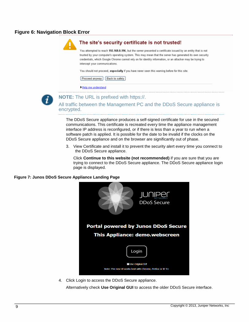
Figure 7: Junos DDoS Secure Appliance Landing Page
4. Click Login to access the DDoS Secure appliance.
Alternatively check Use Original GUI to access the older DDoS Secure interface.

Copyright © 2013, Juniper Networks, Inc 10
5. Enter user name and password when prompted.
Figure 8: Security Log in Page
The default user name is user and the password is password.
To reconfigure the default login values and control access to the DDoS Secure
appliance, see User Access.
NOTE: The first time of use, you will be asked to accept the DDoS Secure EULAs after you have logged in.
First Boot
On the first connection the following licensing screen appears on the Management PC.
Figure 9: First Boot Screen Snippets

Copyright © 2013, Juniper Networks, Inc 11

Copyright © 2013, Juniper Networks, Inc 12
6. Read the End User License Agreement carefully to make sure that you fully understand the Terms and Conditions.
To accept the End User License Agreement:
Click I Accept to accept the terms and conditions.
Click Cancel to proceed no further.
This will cause the system to power-off.
7. Read the Software Specific Entitlement Addendum carefully to make sure that you fully understand the Terms and Conditions.
To accept the Software Specific Entitlement Addendum:
Click I Accept to accept the terms and conditions.
Click Cancel to proceed no further.
This will cause the system to power-off.
On accepting the Terms and Conditions of the license, the DDoS Secure appliance will
re-direct to the overview page.
Overview Page
After successful authentication, the DDoS Secure appliance summary board is displayed.
Figure 10 displays the DDoS Secure appliance overview page.
Figure 10: DDoS Secure Appliance Summary Board
The options available are:
Traffic Monitor—Displays the average speed of data processed, both inbound and outbound, for the appliance, as well as the most active Portals.
Load Status— Displays how busy the DDoS Secure appliance engine is.

Copyright © 2013, Juniper Networks, Inc 13
Attack Status— Displays how aggressively the DDoS Secure appliance is dropping traffic to defend the appropriate resources.
Good Traffic—Displays the distribution of where good traffic is coming from.
Bad Traffic—Displays distribution of where the bad traffic is coming from.
Protected Performance—Displays how busy a protected IP is from an aggregated Charm perspective, and what the average traffic to and from the IP is.
DDoS Secure Appliance Web Interface Screen Layout
This section describes and explains the GUI functions.
Below is the screen layout for the Statistical Display part of the appliance user interface.
Each individual segment of the screen is broken down into categories, as shown in Figure
11.
Figure 11: DDoS Secure Appliance Web Interface Screen Layout
Options on the left hand pane are:
Configuration / Logs— Used to access the configuration and logs window.
Summary Dashboard— Used to display the summary dashboard.
Logout
Configuration /Logs
Page Specific Action View Filters Global View
Summary Dashboard
Menu
Buttons
Display Output
Or
Configuration Input
Operational Mode
Protected Info
Defense Status
Additional Status
Left Pane Center Pane Right Pane

Copyright © 2013, Juniper Networks, Inc 14
Menu Buttons—The menu buttons are in the left pane on the screen; these are described individually in [Error! Reference source not found.]
Options on the center pane are:
Display Output—Used to display output
Configuration Input—Used for configuration input.
NOTE: If the Operational Mode is STANDBY, then the configuration screens in the Center Pane will mainly be Read-Only.
Options on the right pane:
Logout— See [Logout
Operational Mode— See [Operational Mode
Protected Info—See [Protected Information]
Defense Status— The right hand pane describes the state of the DDoS Secure appliance. When an item in Defense Status turns from Black to Red, then DDoS Secure appliance is actively defending this situation. For more information see [Defense Information
Additional Status—See [Additional Status].
Page Specific Action
Some pages in the Statistical display menu have a specific function button or menu. This is
for customizing the displayed output.
View Filters
The View Filter button is available from any page within the statistical display section of the
DDoS Secure appliance. Any value entered into the filter will be set until the filter is
cleared, even when accessing another page within the DDoS Secure appliance Statistical
Display section.
Click view filter option at the top of the center pane to open a text box.
Figure 12: View Filter Option
Filters can be specified in the following format:
aaa.bbb.ccc.ddd/mask—To specify a group of IP addresses using a netmask
aaa.bbb.ccc.ddd/count—To specify a group of IP addresses using a netmask length
aaa.bbb.ccc.ddd—To specify a specific IP address
xxxx::xxxx:xxxx/count—To specify a group of IPv6 addresses using a netmask length
xxxx::xxxx:xxxx—To specify a specific IPv6 address
ABC—To specify a 3 letter country code see [LogoutAS#nnnnn—To specify a specific AS number
Once a filter is active, the view filter button will change to display the actual filter text.
Figure 13: View Filter Option Example

Copyright © 2013, Juniper Networks, Inc 15
Other View Filters
When viewing URL Info, DNS Info or SIP Info, an additional Filter is enabled. This Filter
can then used for doing an appropriate string match.
Select Viewing Option
The Web Interface can be used to monitor different protected IP activity. Select the
protected IP, portal or appliance that you want to monitor from the hierarchy tree as shown
in Figure 14.
Figure 14: Select View Option
The Appliance refers to activity on the local DDoS Secure appliance.
The IP indeterminate or I-portal-name refers to activity against IP addresses in that portal
that have not (yet) been confirmed as genuine, alive, IP addresses.
The displays affected by this entry have the Viewing: icon
The list is initially set global; click on the arrow in front of the folder icon will expand it out
The three options you can select are:
Appliance—The local DDoS Secure appliance
Portal —This option lists defined portals which can be selected or drilled down to list IPs in the portal
IP—This option lists all protected servers by IP
Logout
This will log the user session off the DDoS Secure appliance user interface.

Copyright © 2013, Juniper Networks, Inc 16
Screen Interaction
Expanding Central Pane Area
You can expand the center pane on the user interface. The arrow icons highlighted below
will extend the center pane over the left of right pane when clicked as shown in Figure 15.
Figure 15: Expanding Centre Pane Option
To display the left or right pane after expanding the center pane, click the appropriate arrow
as shown in the Figure 16.
Figure 16: Displaying Left and Right Pane Option
Arranging Table Ordering
While viewing the Miscellaneous Information and Status Information pages, you can
interact with the tables to re-arrange, re-order and hide tables from view.

Copyright © 2013, Juniper Networks, Inc 17
Figure 17: Table Arranging Option
Move/Reorder the specific table –click on the table and drag to the new position.
Hidden Tables
Show Hidden Table
Arranging Column Ordering
Each column in a display can be rearranged by selecting the column and dragging to the
desired position. While finding a position the icon shown in Figure 18 is displayed, and
when an acceptable position is located the new location is highlighted as displayed in
Figure 19.
Figure 18: Table Arranging –Finding Position
Figure 19: Table Arranging –Position Found
Sorting Data and Add-Remove Columns
When the mouse pointer is hovering over column headers, the header will display a down
arrow. This gives access to sort the selected column, or add / remove columns entirely
from the table.
Figure 20: Table Sorting

Copyright © 2013, Juniper Networks, Inc 18
NOTE: Sorting by columns is not fully supported on some screens.
Action Cells
Cells that have a gray mark in the bottom right corner (see below) have an action
associated with the displayed data as shown in Figure 21.
Figure 21: Action location on Cell
Figure 22: Action on Cell
The popup action box (by clicking on the blue location) describes the action (in red) and
clicking the button (in purple) will execute the action as shown in Figure 22.
Action cells can be used to
View graphs
Block / Unblock IPs
Block / Unblock Countries
Track URLs
Track DNS Name Query Type
Track SIP Uris
IP / AS# / Location Details
DDoS Secure appliance uses a GEO-IP database which can be used to find out more
information on Internet IPs.
From within the Statistical display screen shown in Figure 23 shows the pops up
information box that appears when the mouse pointer is hovered over the Location cells.
Figure 23: IP/As/location Details

Copyright © 2013, Juniper Networks, Inc 19
Graphs
The graphs (see below) all have a common interface, each can
Save as .png
Close
Return to previous graph (if drilled down)
Select time range
Define if peak, current, or both values are displayed
Chart legend
Figure 24: Graphs Details
The graph legend is highlighted in purple above.
Hovering the mouse over the legend labels will highlight the corresponding graph data in
bold.
Clicking a specific label will drill down the hierarchy tree, showing data from child node.
To revert back to the original view click the button (highlighted in white).
Time ranges for all graphs are:
Last 1, 3, 6, 12 or 24 Hours
Today, Yesterday, Last Week, Previous Week, Last Month or Custom.

Copyright © 2013, Juniper Networks, Inc 20
Selecting Custom shows additional options as shown in Figure 25 below.
Figure 25: Custom Period Configuration
Manually type in the start date and time in the appropriate text boxes.
Alternatively select the date by clicking the calendar and the time using the drop down.
Select the time period for the graph – 1,3,6,12 hours, 1 week or 1 month.
Then click GO button to generate the appropriate graph.

Copyright © 2013, Juniper Networks, Inc 21
CHAPTER 3
CONFIGURATION AND LOGS
This chapter describes the administration and configuration options available in DDoS
Secure appliance web interface portal.
Configuration Overview
Configuration overview provides the details of the configuration made on the appliance. It
provides details of the general information, user definable details and the table size used.
Click Configuration Overview to update configuration information as shown in Figure 26
Figure 26: Configuration Overview Page
Configuration Overview Page
Copyright © 2013, Juniper Networks, Inc 22
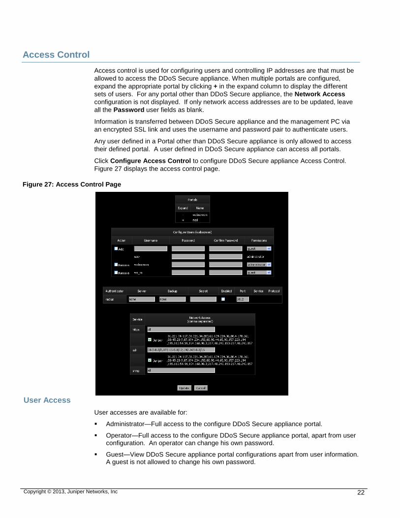
Access Control
Access control is used for configuring users and controlling IP addresses are that must be
allowed to access the DDoS Secure appliance. When multiple portals are configured,
expand the appropriate portal by clicking + in the expand column to display the different
sets of users. For any portal other than DDoS Secure appliance, the Network Access
configuration is not displayed. If only network access addresses are to be updated, leave
all the Password user fields as blank.
Information is transferred between DDoS Secure appliance and the management PC via
an encrypted SSL link and uses the username and password pair to authenticate users.
Any user defined in a Portal other than DDoS Secure appliance is only allowed to access
their defined portal. A user defined in DDoS Secure appliance can access all portals.
Click Configure Access Control to configure DDoS Secure appliance Access Control.
Figure 27 displays the access control page.
Figure 27: Access Control Page
User Access
User accesses are available for:
Administrator—Full access to the configure DDoS Secure appliance portal.
Operator—Full access to the configure DDoS Secure appliance portal, apart from user configuration. An operator can change his own password.
Guest—View DDoS Secure appliance portal configurations apart from user information. A guest is not allowed to change his own password.

Copyright © 2013, Juniper Networks, Inc 23
sso—Change user information.
Table below provides a summary of the information displayed on the DDoS Secure access
control page:
Table 1: Access Control Page Details
FIELD DETAILS
Username This field needs to be configured when adding a new user. A username must start with a
lower case letter, with additional characters made from a mix of lower case letters, digits,
underscores and hyphens. Users are unique across all portals.
Password Enter a value here if you want to change the password. A password must contain
(ASCII) printable characters with a minimum of 6 characters and a maximum length of 35
characters.
Confirm Password Re-enter the new value for the password (as a confirmation).
Permissions Select one of administrator, operator, guest, or sso from the pull down list.
It is recommended that you choose a password of 10 or more characters, no dictionary
words, combination of upper and lower case and numeric and special characters, and that
you should not disclose your password to anyone else. An administrator password should
be available to authorized people for use in an emergency when, after being used, the
administrator should change it.
NOTE: If you lose your password, it is most likely that you will have to re-image your DDoS Secure appliance, so losing all configuration information
External Authenticators
Radius external authentication is supported. This are configured through the CLI set auth
command. The user needs to be defined on the DDoS Secure appliance for both GUI and
SSH access. The authentication sequence is check remote password – if failure, then
check local password.
Network Access
IP addresses can be specified with one of the following formats:
all—All IP addresses are valid.
aaa.bbb.ccc.ddd/mask—To specify a group of IP addresses using a subnet mask.
aaa.bbb.ccc.ddd/count—To specify a group of IP addresses using a subnet mask length.
aaa.bbb.ccc.ddd—To specify a specific IP address.
none—No valid IP addresses.
Values can also be separated using commas. Thus, 11.22.33.44,44.33.22.11 would allow
access from host addresses 11.22.33.44 or 44.33.22.11.

Copyright © 2013, Juniper Networks, Inc 24
NOTE: The value all has the highest precedence in a list and will replace all other values, and the value none has the lowest precedence in a list and will be ignored if not used on its own.
The preferred range notation is the aaa.bbb.ccc.ddd/count format. When a new configuration is accepted this preferred format will be used to display the current configuration. Any entries with the /mask format will be replaced with /count. In addition, any redundant values will also be removed, leaving just the larger address ranges that encompass the redundant values.
Network Services
https—Access to the DDoS Secure appliance is strictly controlled. By default, any IP
address can access the appliance via a secured https web connection. If users try to
connect to the regular http port using the home page (http://w.x.y.z/), they will get
immediately redirected to the secured https web connection (https://w.x.y.z/). Only valid
users [User Access] will be able to access the appliance. It is suggested that this is locked
down to a specific set of IP addresses if the management interface is directly connected to
the Internet.
There is a list of Juniper IP public IP addresses that can easily be enabled or disabled for
Juniper personnel access by selecting or clearing the appliance check box. It is
recommended that this is left enabled (as well as providing access to the appliance
Management interface through firewalls and so on) so that Juniper staff can quickly help
you in DDoS Attack scenarios.
SSH—By default, only private (RFC1918) and Juniper Public IP addresses can access the
appliance via an ssh connection. A Command Line Interface (CLI) is provided. Only valid
users [User Access] will be able to access the CLI. It is strongly suggested that this is
locked down to a specific set of IP addresses if the management interface is directly
connected to the Internet. New connections are rate limited, so if there is a connection
timeout failure, wait a few minutes before trying again.
There is a list of Juniper IP public IP addresses that can easily be enabled or disabled for
appliance personnel access by checking or un-checking the appliance check box. It is
recommended that this is left enabled (as well as providing access to the appliance
Management interface through firewalls and so on) so that Juniper staff can rapidly help
you in DDoS Attack scenarios.
SNMP—By default, SNMP access is not enabled. SNMP access can be enabled for third-
party packages such as HP Openview. If SNMP traps are enabled, then the trap receiver
address is automatically included in this field.
Configure Interfaces
The Interface Link Modes need to be correctly set for your network infrastructure to provide
optimal network speeds. Link speed auto-detection will fail (usually falling back to half
duplex) if the other end of the link is set to a fixed speed.
Click Configure Interfaces to configure the DDoS Secure Interfaces. Figure 28 shows the
configure interface page.

Copyright © 2013, Juniper Networks, Inc 25
Figure 28: Configure Interface Page

Copyright © 2013, Juniper Networks, Inc 26
NOTE: These values are not configurable when running as an Application instead of as an appliance. They are configurable through the appropriate interface of the third-party party hardware platform.
For Fail-Safe cards, the Protected and Internet speed definitions should be identical and a test executed by taking the DDoS Secure Engine offline to validate that traffic can still flow, bypassing the appliance. If there is a change in switch port speeds (For example: Internet 1G, Protected 100M), then auto should only be configured for both interfaces, and on the router / switch ports to which the appliance is connected.
Common Interface Displayed Information
For an appliance where there are more than one interfaces in use for the Internet /
Protected data path, additional columns are added for each extra interface.
If CDP or LLDP packets are detected on an interface, information contained within those
packets is displayed where appropriate.
For Fail-Save cards, the current state of the Transmitter (TX) and Receiver (RX) are
prefixed with a - (off) and + (on).
The underlying Linux associated Ethernet name (ethX) is also displayed.
Table below provides a summary of the information displayed on the DDoS Secure
Interface page:
Table 2: DDoS Secure Interface Page Details.
FIELD DETAILS
Internet Interface Definition
Interface Link Mode If the switch / hub that this interface is connected to is hard coded to a specific
speed / duplex, then the Interface Link Mode MUST be set to the same value.
The default value of auto tells the Interface to negotiate interface speed / duplex.
The currently detected speed / duplex is shown in the third, or subsequent
column.
I/F Flow Control Mode The flow control mode controls the automatic generation of (Tx) and response
(Rx) to Ethernet PAUSE frames on this interface. The default value of auto (only
valid if Link Mode is set to auto) tells the Interface to negotiate flow control. The
currently detected flow control is shown in the third or subsequent column.
Interface Name The name of the interface.
MTU (without MAC Header)
Size
This is used to define the MTU packet size for the data path between the Internet
and the Protected IPs. For Jumbo Frame support, this would be set to 9216.
CDP Packet Info Generation This is used to enable / disable the generation of CDP packets by the DDoS
Secure appliance on all of the interfaces, except in the case of KVM / Xen
hypervisor versions when it is only sent out of the Internet Interface.

Copyright © 2013, Juniper Networks, Inc 27
Link Fault Pass Through When this is enabled, if there is a link failure on, say, the Internet interface, then
the DDoS Secure appliance will turn off the transmitter on the Protected interface
so that the protected switch sees the link failure on the other side of the appliance.
This is always implicitly enabled for the KVM / Xen hypervisor versions.
Protected Interface Definition
Interface Link Mode If the switch / hub that this interface is connected to is hard coded to a specific
speed / duplex, then the Interface Link Mode MUST be set to the same value.
The default value of auto tells the Interface to negotiate interface speed / duplex.
The currently detected speed / duplex is shown in the third, or subsequent
column.
I/F Flow Control Mode The flow control mode controls the automatic generation of (Tx) and response
(Rx) to Ethernet PAUSE frames on this interface. The default value of auto (only
valid if Link Mode is set to auto) tells the Interface to negotiate flow control. The
currently detected flow control is shown in the third or subsequent column.
Interface Name The Internet and Protected interfaces can easily be swapped over (if, for example,
there is a cable mis-configuration) by clicking on Swap Internet and Protected
Interfaces (only available if not running in an Active / Standby pair).
DataShare Interface Definition
DataShare Interface This interface is used to share (Configuration, State and Incident) information
between DDoS Secure appliances (configured as Fail-Over or State sharing). If
this interface is not configured with an IP address, then the information is shared
over the Management Interface which potentially can make the management
network busy.
If any of the logging servers have an IP address that is in the Data Share Network
IP address space, then traffic to the logging server will be routed over the Data
Share Interface.
IP Address This is the IP Address of the Data Share Interface.
Note: The Data Share Interface must NOT have an IP address that is in the same
network as the Management Interface to prevent routing confusion.
Network Mask The Network Mask of the Data Share Interface.
Management Interface Definition
IP Address This is the IP Address of the Management Interface.
Note: The Management Interface must NOT have an IP address that is in the
same network as the DataShare Interface to prevent routing confusion.
Network Mask The Network Mask of the Management Interface.

Copyright © 2013, Juniper Networks, Inc 28
Gateway IP Address The IP address of the router that the DDoS Secure appliance needs to use to get
to an IP address that is not on the local LAN.
DNS Server Address(es) The DNS servers to use if any URLs (for example geoip data updates) need to be
looked up.
Interface Link Mode If the switch / hub that this interface is connected to is hard coded to a specific
speed / duplex, then the Interface Link Mode MUST be set to the same value.
The default value of auto tells the Interface to negotiate interface speed / duplex.
The currently detected speed / duplex is shown in the third, or subsequent
column.
I/F Flow Control Mode The flow control mode controls the automatic generation of (Tx) and response
(Rx) to Ethernet PAUSE frames on this interface. The default value of auto (only
valid if Link Mode is set to auto) tells the Interface to negotiate flow control. The
currently detected flow control is shown in the third or subsequent column.
Configure Specific Routing Information
Specific Routing Information Normally this does not need to be defined as the default gateway is sufficient.
Remote CIDR The IP address or network to reach in aaa.bbb.ccc.ddd/count format.
Gateway This is the gateway to route traffic to the CIDR.
Configure DDoS Secure
The parameters displayed in Figure 29 should be set on the DDoS Secure appliance
immediately after the first power-up. These parameters are used by the appliance
algorithm to tune responses to attacks. The defaults shown will be used if no user-defined
values are supplied. Click Configure DDoS Secure to configure DDoS Secure appliance.

Copyright © 2013, Juniper Networks, Inc 29
Figure 29: DDoS Secure Configuration
This screen is divided into five parts. They are as follows:
First Part—Describes the topology of the network on the Internet side of the DDoS Secure appliance.

Copyright © 2013, Juniper Networks, Inc 30
Second Part—Describes the DDoS Secure appliance operation.
Third Part—Describes who the DDoS Secure appliance is going to be sharing information with.
Fourth Part—Describes the topology of the network on the Protected side of the DDoS Secure appliance.
Fifth Part—Describes the Pseudo Layer 3 network information (primarily used for VMware).
Internet Gateways (based on MAC Addresses)
This section describes the topology of the network on the Internet side of the DDoS Secure
appliance. If the appliance has been running for a short time, it is quite likely that some, if
not all, of the systems connected will be detected by MAC address. Within this section the
speed and packet rate that a particular device can support can only be configured with
respect to its MAC address. The IP address of a device (known as a Gateway) is self-
learning and cannot be modified, as it is only provided to act as a visual aid. An address of
0.0.0.0 means that no IP address has (yet) been seen for the MAC address. It is possible
that the Internet Gateway may initially have a non-local Internet address, but eventually the
appliance will learn the actual IP address of the Gateway.
Table below provides a summary of the information displayed on the DDoS Secure
Configuration page:
Table 3: Configure Internet MAC Addresses
FIELD DETAILS
Configure Internet MAC Address
Gateway IP The gateway IP address.
MAC Address The MAC address is the 6 byte MAC (or NIC) address of the interface card on the
Gateway. If the DDoS Secure appliance is sitting on a VLAN / MPLS trunked or tunneled
connection, then the appropriate information will be shown as well.
To Speed (bps) The maximum data rate that the Gateway device can accept for passing on to whatever is
behind the Gateway. For example, if the Gateway were connected to a 1544Kbps (T1)
line, then the speed should be defined as 1544K, or 1.544M. Speed can be specified in
units of K (1,000), M (1,000,000) or G (1,000,000,000). 0 or U means unrestricted. This
speed is used in the appliances algorithms for determining when bandwidth should be
controlled.
To Rate (pps) The maximum packet rate (Packets Per Second) that the gateway device can accept for
passing on to whatever is behind the gateway. Speed can be specified in units of K
(1,000), M (1,000,000) or G (1,000,000,000). 0 or U means unrestricted. It is
recommended that you use the Suggested Rate if the maximum packet handling rate is
not known.

Copyright © 2013, Juniper Networks, Inc 31
Suggested Rate
(pps) The recommended default is normally one quarter of the theoretically maximum number of
small packets that can fit down the To Speed of the gateway. On lower bandwidth links
(links with a bandwidth less than 8 Mb/s) the recommended value will be higher than one
quarter of the theoretical maximum, and on higher speed links, this may be less than one
quarter.
Adding Internet MAC Address
You can define an Internet Gateway MAC Address that has not been auto-detected. You
will need to ensure that the Add check box has been selected, and then click Update (at
the end of the configuration screen, or top right) for a new item to be included. VLAN
and/or MPLS information can be included by using the following prefixes:
v—VLAN
q—QINQ
u—Unicast MPLS label
m—Multicast MPLS label
IP6in4—IPv6 traffic tunneled in IPv4
GRE—IPv4 traffic in a GRE tunnel
Defined Internet MAC Address(es)
This section contains all the defined Internet MAC Addresses. Checking the Remove
check box will remove inactive Internet MAC Addresses from the display. Click on Update
to confirm this change.
Auto-detected Internet MAC Address(es)
This section contains all Internet MAC Addresses detected by the appliance, apart from
those reported above. Checking the Include check box will move this MAC Address into
the Defined Internet MAC Addresses section, where interface speeds can be modified. It is
possible to purge out all the Auto-detected Internet MAC Addresses by clicking on Delete
All. Inactive auto-detected MAC Addresses will be automatically deleted after five days.
Configuring Appliance
Table below, provides a summary of the information displayed on the appliance
configuration page:
Table 4: Appliance Configuration Page Details
FIELD DETAILS
Configure Appliance
Host Name The default for the host name is the IP address of the DDoS Secure appliance.
Changing this entry causes the name in the browser tab to be updated
appropriately, as well as the system name in any generated CDP packets.

Copyright © 2013, Juniper Networks, Inc 32
Operational Mode The DDoS Secure appliance is capable of operating in different modes, some of
which are primarily used for diagnostic purposes.
Defending is the default setting, which means that the DDoS Secure appliance
is behaving normally, passing packets and defending as required.
Defending-NoStateLearn. For the first five minutes following a reboot, or a
network cable being plugged in, the appliance bypasses its normal State Table
rigorous checking and re-syncs state with any active existing connections.
These five minutes of grace prevent the blocking of packets from existing
connections active at the time of the appliance restarting. This can be
overridden by setting the DDoS Secure appliance into Defending-
NoStateLearn mode. Doing this will cause a substantial number of connections
to be dropped, and so is not normally recommended.
Logging is where the appliance monitors the traffic and flags any attacks
detected but does not drop any packets prior to transmission out of the opposite
interface. Consequently, some of the entries in TCP/UDP/ICMP/Other Info
display pages may be highlighted in yellow to flag these discrepancies. Some
of the other reported statistics might be skewed by the fact that packets should
have been dropped, but were not seen. In this mode, the appliance is allowed to
proactively generate packets (such as TCP Keep-Alives to test for genuine idle
connections, or Fail-Over heartbeats).
Logging-NoKeepAlives is the same as Logging, but TCP Keep-Alives will not
be proactively generated. The appliance will however, still generate Fail-Over
heartbeats if configured for Fail-Over. Running in this mode will cause a higher
incidence of Blocked State – No State Incidents as the DDoS Secure
appliance is unable to determine if a session has expired or not.
Logging-Tap is where the appliance monitors traffic that is picked up by its
Internet Interface and flags any attacks detected but does not pass any packets
to or from the Protected Interface. If this mode is enabled, one or more
protected IPs, or one or more Protected Gateways that are actually connected
to the Internet Interface have to be defined as sitting behind the DDoS Secure
appliance, so that the appliance knows which protected IPs are being protected
for defense purposes. When running in this mode, it is also advisable to
configure the Internet Gateways. It should be noted that the sequencing of
packets received on the tap port may be in the wrong order if the switch is
mirroring multiple ports– the wrong ordering can confuse the DDoS Secure
appliance state logic giving rise to a lot of false positives.
Note: Use of this option is NOT recommended.
Bypass-Software is where the appliance passes all the traffic directly through
to its other interface via the kernel address space. The appliance does not
monitor the traffic for attacks and therefore does not have the capability to drop
any attack packets.
Bypass-FS-Hardware is where the appliance passes all the traffic directly
through to its other interface by forcing the Fail-Safe card into bypass mode.
The appliance does not monitor the traffic for attacks and therefore does not
drop any packets.
Note: Logging-Tap and Bypass-Software modes are only available when the
DDoS Secure appliance is not running in a High-Availability configuration.
Note: Bypass-FS-Hardware mode is only available when the DDoS Secure
appliance is not running in a High-Availability configuration, and a Fail-Safe card
is being used.

Copyright © 2013, Juniper Networks, Inc 33
Override Portal / Protected
Logging modes
Check this box if you want this appliance to override any Portal or Protected IP
settings and force them to be Defending no matter how they are configured.
Note: If the appliance is overall in Logging mode, then this option will have no
effect.
Note: If a client IP address is in the White List, then the White Listed IP will still
be allowed through as it is not affected by this option.

Copyright © 2013, Juniper Networks, Inc 34
High Availability Mode The DDoS Secure appliance is capable of operating in different High Availability
modes.
Standalone— The DDoS Secure appliance is to operate in Standalone Mode.
Traffic is passed through, based on the Operational Mode. Spanning Tree
(BPDU) packets are passed through. If there is a Fail-Safe card, then this
DDoS Secure appliance will go into by-pass if there is a software shutdown, or a
power failure.
Note: This mode cannot be selected if the DDoS Secure appliance is currently
running in a HA cluster.
Standalone-NoFS— The DDoS Secure appliance is to operate in Standalone
Mode, even if it is licensed for Fail-Over. Traffic is passed through, based on
the Operational Mode. Spanning Tree (BPDU) packets are passed through. If
there is a Fail-Safe card, then this DDoS Secure appliance will go into no-link
status if there is a software shutdown, or a power failure.
Note: This mode cannot be selected if the DDoS Secure appliance is currently
running in a HA cluster.
Active-Standby—The DDoS Secure appliance is to negotiate with any other
DDoS Secure appliances as to whether an Active-Standby relationship can be
set up. If a partner is found, then this DDoS Secure appliance will be either the
Active or Standby partner. BPDU packets are dropped. If a fail-safe card is
being used, the card will be set to dual-port mode to disable the fail-safe
functionality.
Active-Standby-FS—The DDoS Secure appliance is to negotiate with any
other DDoS Secure appliances as to whether an Active-Standby relationship
can be set up. If a partner is found, then this DDoS Secure appliance will be
either the Active or Standby partner. BPDU packets are dropped only if a DDoS
Secure appliance engine is running. If a fail-safe card is being used, and both
DDoS Secure appliances are alive, both cards will be set to dual-port mode so
that a single DDoS Secure appliance failure will not cause a network short-
circuit. If only one DDoS Secure appliance is available in the HA cluster, then
its card will be set to bypass-capable, so that if there is a failure of the single
DDoS Secure appliance, traffic will pass through the fail-safe card. If one DDoS
Secure appliance is trying to boot, and the partner is down with its fail-safe card
in bypass mode, then the booting DDoS Secure appliance will not come out of
the Probe state until the bypass link is removed.
Priority—This can only be defined if High Availability Mode is set to
Active-Standby. The priority is configurable to have a value
between –127 to 127 inclusive. If a Fail-Over cluster has different
priorities for the individual DDoS Secure appliances, the DDoS
Secure appliance with the highest numerical priority will be the
default active of the cluster and will take over one minute after
successfully booting, or the priority is changed.
Grouping ID—A DDoS Secure appliance can only establish an
Active-Standby relationship with another DDoS Secure appliance
with the same Grouping ID. Having different Grouping IDs allows
multiple HA pairs to co-exist in the same network environment.

Copyright © 2013, Juniper Networks, Inc 35
Asymmetric Routing With connection state being shared between DDoS Secure appliances, it is
possible to set up a network where there is asymmetric routing – or data
flows in one direction through a DDoS Secure appliance and back out
through another DDoS Secure appliance. There is a potential timing
window where state has been not yet been updated (usually with idle
servers) before the return response packet is seen. Checking the
Asymmetric Routing check box removes some of the state checking but
marginally increases the risk of not properly defending the protected IP
addresses. If operating in an Asymmetric environment, it is recommended
that you check this box.
Auto Black-Listing
Auto Temporary Black-List IP
Address It is possible to get DDoS Secure appliance to auto-black-list IP addresses if
their error rate is running over a specified threshold. Setting the check box
here enables this functionality. IP Addresses that have been black-listed
will be un-black-listed automatically by the DDoS Secure appliance when
the core engine decides that it is safe to do so – usually after 5 minutes of
no traffic from this IP address.
Note: The Auto Black-List system will never block a Protected IP, Preferred
Client, Whitelist Client, or one of the addresses defined as being un-black-
listable in this sub-section.
-Bad Average Irritant (Type 1)
Rate (/s)
If the Bad Irritant Rate (known as Type 1) rolling average rate (as displayed
in Worst Offenders) for an IP address exceeds this value, and Auto Black-
List IP Addresses is enabled, then the IP address in question will be added to
the Auto-Black-Listed IP List. No more traffic is allowed to or from this IP
address until it is removed from the Auto-Black-Listed IP List (either manually
or automatically).
The Type 1 rolling average rate is based on all packets dropped regardless
of attack type and is normally set with a high threshold (the default is 200).
-Bad Average Resource
Usage (Type 2) Rate (/s)
If the Bad Resource Usage (known as Type 2) rolling average rate (as
displayed in Worst Offenders) for an IP address exceeds this value, and Auto
Black-List IP Addresses is enabled, then the IP address in question will be
added to the Auto-Black-Listed IP List. No more traffic is allowed to or from
this IP address until it is removed from the Auto-Black-Listed IP List (either
manually or automatically).
The Type 2 rolling average rate is based on packets dropped against attack
types known to cause aggressive resource consumption on most targets.
Such attacks are usually, but not exclusively, managed by the DDoS Secure
appliance CHARM algorithms and include attacks such as SYN floods and
Connection Floods. For this reason the defense starts with quite a low
threshold (the default is 100). During prolonged attacks it may prove useful
to lower this threshold to match the attack rates of the worst entries in the
Worst Offenders list. If URL Inspection is being used , then this value should
not be dropped to less than two times the inspection bias value (typically 5) –
i.e 10.
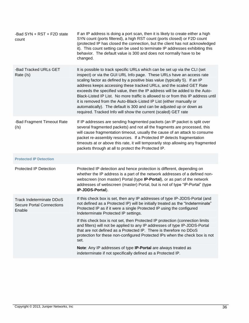
Copyright © 2013, Juniper Networks, Inc 36
-Bad SYN + RST + F2D state
count
If an IP address is doing a port scan, then it is likely to create either a high
SYN count (ports filtered), a high RST count (ports closed) or F2D count
(protected IP has closed the connection, but the client has not acknowledged
it). This count setting can be used to terminate IP addresses exhibiting this
behavior. The default value is 300 and does not normally have to be
changed.
-Bad Tracked URLs GET
Rate (/s)
It is possible to track specific URLs which can be set up via the CLI (set
inspect) or via the GUI URL Info page. These URLs have an access rate
scaling factor as defined by a positive bias value (typically 5). If an IP
address keeps accessing these tracked URLs, and the scaled GET Rate
exceeds the specified value, then the IP address will be added to the Auto-
Black-Listed IP List. No more traffic is allowed to or from this IP address until
it is removed from the Auto-Black-Listed IP List (either manually or
automatically). The default is 300 and can be adjusted up or down as
required. Tracked Info will show the current (scaled) GET rate
-Bad Fragment Timeout Rate
(/s)
If IP addresses are sending fragmented packets (an IP packet is split over
several fragmented packets) and not all the fragments are processed, this
will cause fragmentation timeout, usually the cause of an attack to consume
packet re-assembly resources. If a Protected IP detects fragmentation
timeouts at or above this rate, it will temporarily stop allowing any fragmented
packets through at all to protect the Protected IP.
Protected IP Detection
Protected IP Detection Protected IP detection and hence protection is different, depending on
whether the IP address is a part of the network addresses of a defined non-
webscreen (non master) Portal (type IP-Portal), or as part of the network
addresses of webscreen (master) Portal, but is not of type “IP-Portal” (type
IP-JDDS-Portal).
Track Indeterminate DDoS
Secure Portal Connections
Enable
If this check box is set, then any IP addresses of type IP-JDDS-Portal (and
not defined as a Protected IP) will be initially treated as the “Indeterminate”
Protected IP as if it were a single Protected IP using the configured
Indeterminate Protected IP settings.
If this check box is not set, then Protected IP protection (connection limits
and filters) will not be applied to any IP addresses of type IP-JDDS-Portal
that are not defined as a Protected IP. There is therefore no DDoS
protection for these non-configured Protected IPs when the check box is not
set.
Note: Any IP addresses of type IP-Portal are always treated as
indeterminate if not specifically defined as a Protected IP.

Copyright © 2013, Juniper Networks, Inc 37
Auto Detect Protected IPs If this check box is set, then any IP address of type IP-JDDSS-Portal or IP-
Portal, not configured, will be detected and protected as an individual
Protected IP using the Default Protected IP parameters (overriding the
Indeterminate above). If not set, then this Protected IP traffic will be
aggregated with, and protected by Indeterminate, as if Indeterminate was a
single Protected IP.
Note: To make this option visible requires Track Indeterminate DDoS Secure
appliance portal Connections to be set.
Black / White / Preferred / Default Lists
Black List IP(s) It is possible to block traffic to / from a set of IP addresses or networks on a
permanent basis. Specify IP addresses (in CIDR format) separated by
commas (no spaces) if multiple address blocks are required. IP addresses
allocated to the -bl Country Code (set geoip) are also treated as Black List IP
addresses.
Black List AS#(s) It is possible to block traffic to / from a set of IP addresses or networks on a
permanent basis, based on the Autonomous System (AS) number as used
by BGP routing for the Internet. The AS number information is provided by
MaxMind and is not 100% accurate. Specify AS numbers or AS ranges,
separated by commas (no spaces) if multiple AS blocks are required.
Note: The maximum AS number currently supported is 65535.
Black List Country(s) It is possible to block traffic to / from a set of countries. The countries are
determined from the ip to country tables provided by MaMind (and possibly
updated with the CLI set geoip command), and so are not guaranteed to be
100% accurate. The 3 letter country ids are required, separated by commas
(no spaces) if multiple countries are to be specified. A full list of these
country codes can be found as below, or as observed from the output
information of various statistical outputs. If many countries are to be blocked,
the pseudo all can be used, followed by ! and the 3 letter country code. Thus
all,!GBR means only GBR is allowed (all but GBR is blocked).
By clicking on Black List Country(s), this will bring up a display of all the
Country Codes. The codes that are in Red are always blocked, those in
Orange are (partially) blocked by a filter definition.
-Do not block these
addresses if Country blocked It is possible that a Country needs to be black listed, but that some IP
addresses from within the Country need access through the DDoS Secure
appliance. Specify IP addresses (in CIDR format) separated by commas (no
spaces) if multiple address blocks are required to override the Black List
Country definitions. IP addresses allocated to the -ca Country Code (set
geoip) are also treated as Do not block these addresses if Country blocked.

Copyright © 2013, Juniper Networks, Inc 38
White List IP(s) It is possible to specify an IP network where you have authorized Pen
Testers to work from giving them the ability to do Pen Testing on protected
IPs. Any connections from this network are treated as if the DDoS Secure
appliance engine is running in logging mode, no matter what the actual
operational mode is set to. Thus attacks will be reported, but no packets will
get dropped. If a White List IP is specified, and this address is spoofed
on the Internet, then the spoofer has the potential to seriously DDoS a
protected IP. Use this option with caution, as it is not normally needed. IP
addresses allocated to the -wl Country Code (set geoip) are also treated as
White List IP(s).
White (No logging) List IP(s) It is possible to specify client IP addresses that get preferential treatment
when connecting to a busy protected IP, but nothing is recorded in the logs
for this IP address. Furthermore, this IP address will never get blocked /
dropped. If a White (No logging) List IP address is specified, and this
address is spoofed on the Internet, then the spoofer has the potential to
seriously DDoS a protected IP and there will be nothing in the log files
to report what happened. Use this option with caution, as it is not normally
needed. IP addresses allocated to the -wn Country Code (set geoip) are
also treated as White (No logging) List IP(s).
Note: It is strongly recommended that White List IP(s) is used instead, as
logs of any bad activity will be generated.
Preferred (Charm Boost) IP(s) It is possible to specify IP addresses that get preferential treatment (with a
Charm boost) when connecting to a busy protected IP. If a Preferred
(Charm Boost) IP address is specified, and this address is spoofed on
the Internet, then the spoofer has the potential to DDoS a protected IP.
Use this option with caution, as it is not normally needed. IP addresses
allocated to the -pl Country Code (set geoip) are also treated as Preferred
(Charm Boost) IP(s).
Preferred (Charm Boost)
Country(s)
It is possible to specify Countries that get preferential treatment (with a
Charm boost) when connecting to a busy protected IP. If a Preferred
(Charm Boost) Country is specified, and this address is spoofed on the
Internet, then the spoofer has the potential to DDoS a protected IP. Use
this option with caution, as it is not normally needed.
Default Charm IP(s) It is possible to specify IP addresses that always get first time treatment
when connecting to a busy protected IP. This allows monitoring systems to
always get a first time experience when monitoring response times etc. IP
addresses allocated to the -dc Country Code (set geoip) are also treated as
Default Charm IP(s).
Test Environment
Copyright © 2013, Juniper Networks, Inc 39
Test Environment This check box should not typically be set during normal operation. It is
provided to handle a special case that can arise in test lab situations where
powerful traffic generators are in use. Sometimes these test systems break
RFC rules about TCP port re-usage.
A more detailed explanation about this special case follows:
The TCP rules for connection termination specify that after the final ACK has
been sent in an active close, then that connection must stay in the
TIME_WAIT state for twice the MSL time period. As the MSL time period is
30 seconds, this TIME_WAIT delay on most systems is usually just greater
than 1 minute, but can be as long as 4 minutes.
Some network stress testing tools generate high rates of connections (and
the consequential tear-downs of same) in rates in excess of 100K
connections per second. If these connections come from a single client IP
address to a single protected IP address and port, then any rate higher than
65K connections per minute requires source port re-usage at a rate higher
than 1 per minute. This is in violation of RFCs, and DDoS Secure appliance
would block the port re-usage until at least a minute has passed.
Consequently, the perceived performance of the DDoS Secure appliance is
much lower than expected.
To handle these tools, setting the Test Environment check box reduces this
TIME_WAIT state down to 7 seconds.
Additionally, these tools can take a long time to set up a large number of
connections. DDoS Secure appliance will start timing out these connections
under normal conditions. Setting Test Environment check box increases the
allowed connection set up time to 10 minutes.
Configure Sharing Information
This section describes the sharing details of the DDoS Secure appliance, its configurations,
incidents and connection state. When multiple DDoS Secure appliances are running in an
Active / Standby, or Load Sharing configuration, this information will always be sent to the
IP address of the partner(s). If information needs to be sent to remote IP addresses, then
specifying the appropriate unicast or broadcast addresses here will cause packets to be
sent to that remote set of addresses.
Table below provides a summary of the information of the sharing information
configuration:
Table 5: Configure Sharing Information
FIELD DETAILS
Remote IP The IP address of the remote DDoS Secure appliance or a broadcast address for
appliance in a remote network (to cut down of traffic going between the
appliances).
Note: Configurations can only be transferred to an actual IP address, not a
broadcast address, so three entries (two for configurations, one for incidents/state)
may have to be set up to reduce traffic being sent to a remote pair of appliances.

Copyright © 2013, Juniper Networks, Inc 40
Required Check this box if the remote appliance is required to detect traffic flowing both
ways through a appliance cluster – typically in an Asymmetric Routing
environment using fail-safe interface cards. If this partner becomes unavailable,
the local appliance will take itself into a degraded (pseudo logging) state to make
sure that it does not simply block any traffic until the situation has been fixed.
Via Gateway To send data to an IP address that is not on the local LAN, either the Default
Gateway can be used, or a specific next hop router’s address can be specified if
Data is to be sent over the Data-Share interface.
Note: If the Data-Share interface is defined, then all shared information MUST be
routed via this interface across the appliances.
Config If selected, any configuration changes will be sent to this IP address. This address
must be a unicast address as the configuration is transferred using the https
protocol.
Incident If selected, any appliance defense information will be sent to this IP address using
port 5556/udp.
State If selected, any appliance connection state information will be sent to this IP
address using port 5555/udp.
Configuring Protected Gateways (based on MAC Address)
This section describes the topology of the network on the protected side of the DDoS
Secure appliance. If the appliance has been running for a short time, it is quite likely that
some, if not all, of the systems connected will be detected by MAC address. Within this
section, only MAC addresses, the speed and packet rate that the particular device can
support can be configured. The IP address of a device (known as a gateway) is self-
learning and cannot be modified as the information is provided as an aid only. An address
of 0.0.0.0 means that no IP address has (yet) been seen for the device. It is possible that
the protected gateway may initially have a non-local protected IP address, but eventually
the appliance will learn the actual IP address of the gateway.
Table below provides a summary of the information of the protected gateway configuration:

Copyright © 2013, Juniper Networks, Inc 41
Table 6: Configure Protected Gateway
FIELD DETAILS
MAC Address 6 byte MAC (or NIC) address of the interface on the gateway. If the DDoS Secure
appliance is sitting on a VLAN or MPLS trunked connection, then the appropriate
information will be shown as well. This information is encoded as follows with the
following prefixes:
v—VLAN
q—QINQ
u—Unicast MPLS label
m—Multicast MPLS label
IP6in4—IPv6 traffic tunneled in IPv4
GRE—IP traffic in a GRE tunnel
To Speed (bps) Maximum data rate that the gateway device can accept for passing on to whatever
is behind it. For example, if the gateway were connected to a 10Mbps connection,
then the speed would be defined as 10M. Speed can be specified in units of K
(1,000), M (1,000,000) or G (1,000,000,000), 0 means unrestricted. This speed is
used in the appliance’s algorithms for determining when bandwidth should be
controlled.
To Rate (pps) Maximum packet rate that the gateway device can accept for passing on to whatever
is behind the gateway. It is recommended that you use the Suggested Rate if the
maximum packet handling rate is not known.
Suggested Rate (pps) The recommended default is one quarter of the theoretically possible maximum
number of small packets that can fit down the To Speed of the gateway. On lower
bandwidth links (links with a bandwidth less than 8Mb/s) the recommended value will
be higher than one quarter of the theoretical maximum, and on higher speed links,
this may be less than one quarter.
New Protected MAC Address
Table below provides a summary of the information of the new protected MAC
configuration:

Copyright © 2013, Juniper Networks, Inc 42
Table 7: New Protected MAC Address
FIELD DETAILS
MAC Address You can define a Protected MAC Address that has not been auto-detected.
Check Add check box, and click Update for a new item to be included. VLAN
and/or MPLS information can be included by using in the following prefixes:
v—VLAN
q—QINQ
u—Unicast MPLS label
m—Multicast MPLS label
IP6in4—IPv6 traffic tunneled in IPv4
GRE—IP traffic in a GRE tunnel
Defined Protected MAC
Address(es)
All the defined Protected MAC Address. Check Remove check box and click
Update to remove inactive Protected MAC Addresses.
Auto-detected Protected MAC
Address(es)
All Protected MAC Addresses detected by the appliance, apart from those
reported above. Check Include check box and click Update to move this MAC
address into the Defined Protected MAC Addresses section, where interface
speeds can be modified. It is possible to purge out all the Auto-detected
Protected MAC Addresses by clicking on Delete All. Inactive auto-detected
MAC addresses will be automatically deleted after five days.
Pseudo Layer 3 Configuration
The appliance is a layer 2 device, and so requires the Internet and Protected interfaces to
be working in promiscuous mode in order to pass all the traffic through. There are some
virtual environments where promiscuous mode does not work correctly, so DDoS Secure
provides a mechanism whereby it can sit in a layer 2 network, but actually separates the
network into 2 parts by being a “man in the middle” for arp requests. The appliance needs
to be told at a minimum what is the local network IP network as well as the default gateway
IP out of the network. Currently only IPv4 is supported
Table 8 provides a summary of the information of the pseudo layer 3 configuration:
Table 8: Configure Pseudo Layer 3
FIELD DETAILS
Local CIDR The local network definition in CIDR format. It is possible to specify multiple network
definitions.
Remote CIDR A remote network accessible from one of the local networks. The keyword default is also
valid.
Gateway The IP address on the local network that is used to get to the Remote CIDR.

Copyright © 2013, Juniper Networks, Inc 43
DDoS Secure Portal Configuration
The following parameters should be set on the DDoS Secure appliance soon after the first
power-up. These parameters are used by the appliance algorithm to tune responses to
attacks. The defaults shown will be used if no user-defined values are supplied.
Click Configure Portals to configure the DDoS Secure appliance Parameters. Figure 30
displays the DDoS Secure portal configuration page.
Figure 30: DDoS Secure Portal Configuration Page.
This screen is broken into four parts.
First Part—Describes all the different portals configured on the DDoS Secure appliance.
Second Part—Describes the Filters in use in a portal.
Third Part—Describes the Filter Aggregations in use in a portal and the final part describes the Protected IPs that are in use in a portal.
Fourth Part—Describes the Protected IPs that are in use in a portal
It is possible to allocate (not necessarily contiguous) blocks of addresses (networks and or
single IP addresses) to what are known as portals, which can, if required, be managed
separately by designated users. This gives the ability for Customers, Clients or Business
Units to be able to manage what DDoS Secure appliance does for their portal. Any user
that has full managerial access can override these portal configurations. The master
portal is known as webscreen.
The master portal defines what the DDoS Secure appliance is to protect, and then all the
other portals have a subset of (but cannot overlap with other portals) this master portal
capability.

Copyright © 2013, Juniper Networks, Inc 44
Table below provides a summary of configure portal details displayed on the DDoS Secure
Portal Configuration page:
Table 9: Configure Portal Details
FIELD DETAILS
Configure Portals
Expand When multiple portals are configured, expand the appropriate portal by clicking on
the + in the Expand column to display the different portal sets of filter / filter
aggregation / protected IP.
Name This is the name of the portal.
Type This portal can be a list of IP addresses, or associated with a particular
VLAN/MPLS definition.

Copyright © 2013, Juniper Networks, Inc 45
Address(es) It is possible to specify here all the valid protected IP addresses that your DDoS
Secure appliance is protecting for a portal. For the master portal (webscreen),
this defines all the valid addresses that the DDoS Secure appliance is protecting
– any other portal will be a subset of the webscreen portal. Any inbound traffic will
have to match a portal IP address (or be going to a multicast address or a
broadcast address) to be allowed through. Any outbound traffic will have to come
from a valid portal IP address. It is therefore possible to do simple ingress and
egress filtering by specifying a restricted network here. It is valid to specify an
address group that encompasses, for example, the default gateway IP that is on
the Internet side of DDoS Secure appliance.
IP addresses can be specified as
All—All IP addresses are valid (includes IPv6).
all-ipv4—All IPv4 addresses.
aaa.bbb.ccc.ddd/mask—To specify a group of IPv4 addresses using a
subnet mask.
aaa.bbb.ccc.ddd/count—To specify a group of IPv4 addresses using a
subnet mask length.
aaa.bbb.ccc.ddd—To specify a specific IPv4 address.
aaa.bbb.ccc.ddd-eee.fff.ggg.hhh—To specify a range of IPv4 addresses.
xxxx::xxxx:xxxx/count—To specify a group of IPv6 addresses using a subnet
mask length.
xxxx::xxxx:xxxx—To specify an IPv6 address.
xxxx::xxxx:xxxx-yyyy:yyyy::yyyy—To specify a range of IPv6 addresses. All
addresses can be "," (comma) separated. Thus 11.22.33.44,44.33.22.11 would
specify the two protected IPs 11.22.33.44 and 44.33.22.11. There can be a
maximum of 30 different entries.
Note: You may need to define an IP address of 0.0.0.0/32 to allow DHCP
requests to pass through the DDoS Secure appliance.
If the portal has been defined at type VLAN, then a, potentially comma separated,
set of VLAN/MPLS definitions need to be defined. These are prefixed as
appropriate with the following letters.
v—VLAN
m—MPLS label
Only the outermost VLAN / MPLS label is selected.
Operation It is possible for portals to be operating in a different operational mode than
defined for the appliance. Here, it is possible to select either defending, or logging.
If the appliance operational mode is set to anything other than defending, then the
portal mode will be the same as the operational mode.

Copyright © 2013, Juniper Networks, Inc 46
Countries It is possible to specify which countries match, and hence are allowed to use this
portal. The countries are determined from the ip to country tables provided by
MaxMind (and potentially modified by the geoip command), and so are not
guaranteed to be 100% accurate. The 3 letter country ids are required, separated
by commas (no spaces) if multiple countries are to be specified. A full list of these
country codes can be found in, or as observed from the output information of
various statistical outputs. If many countries are to be allowed, the pseudo all can
be used, followed by (!) and the 3 letter country code. Thus all,!GBR means that
all traffic, apart from that coming from GBR is matched. The country match always
applies to the Client Internet address, not a protected IP address.
AS#s It is possible to allow traffic to / from a set of IP addresses or networks on a
permanent basis, based on the Autonomous System (AS) number as used by BGP
routing for the Internet. The AS number information is provided is not 100%
accurate. Specify AS numbers or AS ranges, separated by commas (no spaces) if
multiple AS blocks are required. By default, all AS numbers are allowed. The
maximum AS# that can be specified is 65535.
Speed (bps) This is the minimum guaranteed speed (bandwidth) that the portal has available for
use. If the value is set to U or 0, then there is no guaranteed minimum speed
available. The sum of all the individual portals cannot exceed that of the master
portal.
Burst Speed This is the speed that the portal can use if the bandwidth is not being used
elsewhere. Bandwidth will be rate limited for any speeds over the guaranteed
speed based on Charm
ReRoute Under The packet rate under which the DDoS Secure appliance will drop the inserted
route after defined period (default is 5 minutes). This is only applicable if BGP Re-
Routing has been enabled which is done via the CLI.
ReRoute Over The packet rate over which the DDoS Secure appliance will insert a route into
BGP. This is only applicable if BGP Re-Routing has been enabled which is done
via the CLI.
Rate (pps) This is the minimum guaranteed packet rate that the portal has available for use. If
the value is set to U or 0, then there is no guaranteed minimum rate available. The
sum of all the individual portals cannot exceed that of the master portal.
Burst Rate This is the packet rate that the portal can use if the packet rate is not being used
elsewhere. Packet rates will be rate limited at this value based on Charm. It is
usual to keep this value the same as the Rate (pps) value if the Burst Speed is not
more than double the Speed (bps).
Suggested Rate The recommended default is normally one quarter of the theoretically maximum
number of small packets that can fit into the speed of the portal. With lower
bandwidth (bandwidth less than 8Mb/s) the recommended value will be higher than
one quarter of the theoretical maximum, and on higher speed links, this may be
less than one quarter.

Copyright © 2013, Juniper Networks, Inc 47
ReRoute Under The rate under which the DDoS Secure appliance will drop the inserted route after
defined period (default is 5 minutes). This is only applicable if BGP Re-Routing
has been enabled which is done via the CLI.
ReRoute Over The rate over which the DDoS Secure appliance will insert a route into BGP. This
is only applicable if BGP Re-Routing has been enabled which is done via the CLI.
Filters The number of available filters is a limited resource. Here, you can define how
many filters a particular portal is allowed to use. The default value is the number
of filters divided by the number of portals. For the master portal, the number
displayed is the remaining number of filters available for allocation.
Protected IPs The number of available protected IPs is a limited resource. Here, you can define
how many protected IPs a particular portal is allowed to use. The default value is
the number of protected IPs divided by the number of portals. For the master
portal, the number displayed is the remaining number of protected IPs available for
allocation.
(Addresses) The number of defined IP addresses in the portal.
(Used) The number of IP addresses in use in the portal.
Existing Portals
This section contains all the configured portals, including the DDoS Secure portal. It is
possible to remove a portal by checking the Remove check box (the portal must not be
expanded). It is not possible to delete the webscreen portal.
Bandwidth and Port Filters
Bandwidth and Port filters are defined for inbound and outbound traffic. Any new traffic that
matches a specific filter will have session state tracking enabled for that traffic. Any
subsequent traffic matching (taking into account direction) a tracked session will also be
allowed based on the filter. Thus for an inbound connection, an inbound filter that allows
http traffic only (port 80/tcp) and an outbound filter that lets through no traffic, is sufficient to
allow a full http connection to take place.
Any traffic associated with a filter will be rate limited (based on Charm) if it exceeds the
defined bandwidth thresholds – which is separately applied to both directions. If multiple
protected IPs use the same filter, then the threshold is an aggregate for all the protected
IPs. If the protected IPs each use a different filter with the same characteristics, then the
threshold will be on a per protected IP basis.
Each protected IP must have one inbound filter and one outbound filter configured to
control access to and from the protected IP.
There is a non-configurable filter default, which allows most traffic through with a restriction
on valid icmp types and udp port 80. This is the initial default protected IP filter for both
inbound and outbound.
In addition to the non-configurable default filter, there are three predefined configurable
filters. The multicast filter is preset to allow traffic (no tcp and restriction on icmp types)
through and is the default filter for the Global Protected IP Multicast. The broadcast filter is
preset to block all TCP ports, UDP port 7 and all ICMP types, and is the default filter for the

Copyright © 2013, Juniper Networks, Inc 48
Global Protected IP Broadcast. The intercept filter is initially set to only allow TCP, and this
is used in conjunction with the CLI set wrapper blocked command.
Table below provides a summary of the bandwidth and port filters displayed on the DDoS
Secure Portal Configuration page:
Table 10: Configure Bandwidth and Port Filters Details
FIELD DETAILS
Name This is the name of the filter.
TCP Ports The default value of all allows through all TCP ports. If only a subset of ports such as 80
and 443 are required, it is suggested that only these are enabled. DDoS Secure appliance
will always drop all packets with port numbers not matching the values entered here. Ports
are specified as either an individual port 80, as a range of ports 80-81, a comma separated
list of ports 80,443, or as a combination 80-81,443. The keyword none is also supported.
Any connection that matches the filter is always allowed, as are any response packets
(including an ICMP diagnostic response) as state is maintained on the connection’s
session.
Note: FTP (port 21) is a special case – data connections are handled automatically, so
data ports do not need to be defined, only the control port (21), unless FTPS is being used,
in which case the data ports will have to be configured as well as the control port traffic is
encrypted which the DDoS Secure appliance logic cannot interpret.
HTTP Ports These are the TCP ports that the DDoS Secure appliance will inspect for HTTP traffic.
These ports must also be defined under TCP Ports to be actioned.
UDP Ports The default value of all allows through all UDP ports. If only a subset of ports such as 53
(DNS) is necessary for the correct operation of the protected IPs, it is suggested that only
these are enabled. DDoS Secure appliance will always drop all packets with port numbers
not matching the values entered here. Ports are specified as either an individual port 53, a
range of ports 53-54, a comma separated list of ports 53,100, or as a combination 53-
54,100. The keyword none is also supported. Any UDP request that matches the filter is
always allowed the response packets (including an ICMP diagnostic response) as state is
maintained on the connection. However, this state expires after 30 seconds of inactivity, so
if you have a UDP protocol that can be started from either end (such as port 500 for IPSEC
IKE traffic), you will need to specify the UDP port as being valid in both the inbound and
outbound filter of the protected IP definition.
ICMP Types ICMPv4 types necessary (in addition to valid state matching diagnostic responses) for the
correct operation of all protected IPs being defended should be listed here. The appliance
will deny all other ICMP types whether the protected IPs are under attack or not. Types are
specified as either an individual type 8, as a range of types 3-4, as a comma separated list
of types 3,8, or as a combination 3-4,8. The keyword none is also supported. A full list of
types for ICMP is given in ICMP diagnostic responses that match a valid state for an
existing session are always let through. This includes, for example, ping responses to ping
requests. Currently, the highest RFC ICMPv4 defined type is 18, so the keyword all refers
to types 0 through 18. If other ICMP types are required, they will need to be separately
added in (e.g 0-18,21).

Copyright © 2013, Juniper Networks, Inc 49
ICMPv6 Types ICMPv6 types necessary (in addition to valid state matching diagnostic responses) for the
correct operation of all protected IPs being defended should be listed here. The appliance
will deny all other ICMP types whether the protected IPs are under attack or not. Types are
specified as either an individual type 8, as a range of types 3-4, as a comma separated list
of types 3,8, or as a combination 3-4,8. The keyword none is also supported. ICMP
diagnostic responses that match a valid state for an existing session are always let
through. This includes, for example, ping responses to ping requests. Currently, ICMPv6
uses 0 through 4, and 128 to 154, so the keyword all refers to types 0 through 4, and 128
through 154 inclusive. If other ICMP types are required, they will need to be separately
added in (e.g 0-4,128-154,156).
IP protocols IP protocols (other than TCP, UDP, ICMPv4 and ICMPv6) necessary for the correct
operation of all protected IPs being defended should be listed here. Examples could be
IPSEC (protocols 50 and or 51) or GRE (protocol 47). The appliance will deny all other IP
protocols whether the protected IPs are under attack or not. Protocols are specified as
either an individual protocol 47, as a range of protocols 50-51, as a comma separated list
of protocols 47,50, or as a combination 47,50-51. The keyword none is also supported.
Any IP request that matches the filter is always allowed the response packets (including an
ICMP diagnostic response) as state is maintained for the session. However, this state
expires after 30 seconds of inactivity, so you will need to specify the IP protocol as being
valid in both the inbound and outbound filter of the protected IP definition.
Countries It is possible to specify which countries match, and hence are allowed to use this filter. The
countries are determined from the IP to country tables provided and potentially modified by
the CLI geoip command), and so are not guaranteed to be 100% accurate. The 3 letter
country ids are required, separated by commas (no spaces) if multiple countries are to be
specified. A full list of these country codes can be found in, or as observed from the output
information of various statistical outputs. If many countries are to be allowed, the pseudo
‘all’ can be used, followed by ‘!’ and the 3 letter country code. Thus all,GBR means that all
traffic, apart from that coming from GBR is matched. The country match always applies to
the Client’s Internet address, not a protected IP address.
Networks It is possible to specify which networks match, and hence are allowed to use this filter. The
network match always applies to the Client’s Internet address, not a protected IP address.
Thus it is possible to specify, say, that only certain IP addresses are able to access port 22
on a protected IP. It should be noted that if port 22 is allowed in another filter match as part
of a Filter Aggregation definition, then port 22 may not be blocked as expected. The
network match always applies to the Client’s Internet address, not a protected IP address.
AS#s It is possible to specify which networks matched, based on the Autonomous System (AS)
number as used by BGP routing for the Internet. The AS number information is provided
by MaxMind and is not 100% accurate. Specify AS numbers or AS ranges, separated by
commas (no spaces) if multiple AS blocks are required. By default, all AS numbers are
allowed. The maximum AS# that can be specified is 65535.
Speed (bps) This is the minimum guaranteed speed (bandwidth) that the Filter has available for use. If
the value is set to U or 0, then there is no guaranteed minimum speed available. The sum
of all the individual Filters cannot exceed that of the portal unless the portal is unrestricted.
Burst Speed This is the speed that the Filter can use if the bandwidth is not being used elsewhere.
Bandwidth will be rate limited for any speeds over the guaranteed speed based on Charm.

Copyright © 2013, Juniper Networks, Inc 50
Rate (pps) This is the minimum guaranteed packet rate that the Filter has available for use. If the
value is set to U or 0, then there is no guaranteed minimum rate available. The sum of all
the individual Filters cannot exceed that of the portal unless the portal is unrestricted.
Burst Rate This is the packet rate that the Filter can use if the packet rate is not being used elsewhere.
Packet rates will be rate limited at this value based on Charm. It is usual to keep this value
the same as the Rate value if the Burst Speed is not more than double the Speed (bps).
Suggested Rate The recommended default is normally one quarter of the theoretically maximum number of
small packets that can fit into the Speed of the Filter. With lower bandwidth (bandwidth
less than 8Mb/s) the recommended value will be higher than one quarter of the theoretical
maximum, and on higher speed links, this may be less than one quarter.
Configure Filter Aggregations
Multiple Filters may be required for a protected IP, each having its own bandwidth and port
characteristics. With Filter Aggregations, you can define a list of (up to seven) filters to
search through looking for the first match on the port and / or protocol, which is then used.
It is possible for a Filter Aggregation to refer to another, previously defined, Filter
Aggregation. Thus it is possible to build a base-line Filter Aggregation and create other
special configurations keyed off the base-line.
If a Filter Aggregation is used, and a particular port is not defined / matched in any of the
seven sections, then any traffic to that port will be dropped.
These Filter Aggregations do not appear on the Statistical Information pages and are an
aid to configuring the Protected IP Filter definitions.
Table below provides a summary of the configuration filter aggregation:
Table 11: Configure Filter Aggregations Details
FIELD DETAILS
Name This is the name of the Filter Aggregation. It is suggested that the Filter Aggregation Name
is easily differentiated from Filter Name for ease of configuration troubleshooting.
Filter [1 2 3 4 5 6 7] Select a Filter Name or a Filter Aggregation Name from the pull-down list. It is valid (but
unusual!) to have the -undefined- entry between genuine entries.
Configure Protected IPs
Any auto definitions below are automatically updated in the configuration file every
midnight as they provide a starting value hint to the DDoS Secure algorithms whenever the
DDoS Secure engine is restarted. This is only true for protected IPs that have been
defined, not just ‘detected’.
Table below provides a summary of the configuration filter aggregation:

Copyright © 2013, Juniper Networks, Inc 51
Table 12: Configure Protected IPs
FIELD DETAILS
Protected IP The IP address of the IP being protected.
TCP Backlog per port The maximum number of connection attempts, per port, that a protected IP can
hold in a partially opened state. This is known as the hard limit and a value of 1000
per protected IP is usually acceptable but may be lowered to around 50 for a
sensitive protected IP. If this value is prefixed by auto-, then the DDoS Secure
appliance engine will try to automatically adjust this value based on how the
protected IP is responding. The default is auto-1000. A value of 0 or U means
that there is no backlog checking. The DDoS Secure appliance Charm algorithm
will reduce the likelihood of a user making a connection as the current count
increases towards the (potentially automatically determined) hard limit.
The auto- logic only recalculates for ports or IP addresses that are known to be
Active – i.e. not filtered out by an internal firewall.
The auto- logic may get confused if SYN Cookies are in use by the Protected IP,
as the Protected IP will always quickly respond to the SYN request. If this is the
case, then auto- may not be appropriate, and, depending on the power of the
Protected IP, would typically have a value of 1000 up to 5000.
If the Protected IP hard limit is unknown, and auto- is not appropriate, set this hard
limit value to the value reported under Suggested TCP Backlog for the
appropriate Protected IP, and then review the situation to see if this value
significantly changes. If Syn Floods are being reported, there are very few
connections in the SYN state and the Protected IP is not overloaded, this value can
be increased.
A protected default value of the IP for maximum TCP backlog queue per port
differs depending on its operating system. On Linux systems, for example, this
hard limit can be deter mined by issuing the command: sysctl
net.ipv4.tcp_max_syn_backlog\. On Microsoft Windows servers, this value is
stored in a variable (TcpMaxHalfOpen) in the registry entry:
[HKEY_LOCAL_MACHINE\SYSTEM\CurrentControlSet\Services\Tcpip\Parameter
s].
Suggested TCP Backlog The value that the DDoS Secure appliance engine believes is a better value to use.
This value can be incorrectly calculated if the Protected IP is using SYN Cookies.

Copyright © 2013, Juniper Networks, Inc 52
Max Open Connections The maximum number of open connections (in an active data transfer state) that
can be handled by the Protected IP. This is known as the hard limit and a value of
1000 per protected IP (but considerably higher for a load-balancer) is usually
acceptable but may be lowered to around 50 for a sensitive protected IP. If this
value is prefixed by auto-, then the DDoS Secure appliance engine will try to
automatically adjust this value based on how the protected IP is responding. The
default is auto-1000. A value of 0 or U means that there is no connection
checking. The DDoS Secure appliance Charm algorithm will reduce the likelihood
of a user making a connection as the current count increases towards the
(automatically determined) hard limit.
If the protected IP hard limit is unknown, and auto- is not appropriate, set this hard
limit value to the value reported under Suggested Connections for the appropriate
Protected IP, and then review the situation to see if this value significantly changes.
If Connection Floods are being reported, and the Protected IP (by checking the IP
itself) is not overloaded, this value can be increased.
Suggested Connections The DDoS Secure appliance engine believes is a better value to use.
Max Conn Rate The maximum number of new connections per second that can be handled by the
Protected IP. This is known as the hard limit. This could be a limit imposed by the
transaction rate of a backend database server. If this value is prefixed by auto-,
then the DDoS Secure appliance engine will try to automatically adjust this value
based on how the protected IP is responding. The default is auto-1000. A value of
0 or U means that there is no connection rate checking. The DDoS Secure
appliance Charm algorithm will reduce the likelihood of a user making a connection
as the current count increases towards the hard limit.
For HTTP connections using HTTP/1.1, the second and subsequent GET / HEAD /
POST requests are also treated as a new connection request for calculating rates,
as well as an additional GET request.
If the protected IP hard limit is unknown, and auto- is not appropriate, set this hard
limit value to the value reported under Suggested Conn Rate for the appropriate
Protected IP, and then review the situation to see if this value significantly changes.
If Connection Rate Floods, or GET Rate Floods are being reported, and the
Protected IP is operating within limits, this value can be increased.
Suggested Conn Rate The value that the DDoS Secure appliance engine believes is a better value to use.
This value can be incorrectly affected by the protected IP silently dropping TCP
connections.

Copyright © 2013, Juniper Networks, Inc 53
Max Active GETs The maximum number of concurrent HTTP page requests that a protected IP can
process. An example of this is the maximum number of ASP Threads that an IIS
Server can handle. The DDoS Secure appliance code tracks the GET / HEAD /
POST requests, incrementing a counter, and then decrementing this counter when
the HTTP response starts to come back. The default is auto-1000. A value of 0 or
U means that there is no concurrent GET checking.
If the protected IP hard limit is unknown, and auto- is not appropriate, set this hard
limit value to the value reported under Suggested GETs for the appropriate
Protected IP. If GET Floods are being reported, and the Protected IP is operating
within limits, this value can be increased.
Note: Do not set this to 0 or U if you want the DDoS Secure appliance to defend
against URL attacks.
Suggested GETs The value that the DDoS Secure appliance engine believes is a better value to use.
Inbound Filter The filter will be applied to all sessions initiated to your protected IP (and response
packets). If this is a Filter Aggregation definition, then the first Filter match in the
aggregate list will be used. If there is no Filter match, then the packet will be
dropped.
Outbound Filter The filter will be applied to all sessions initiated from your protected IP (and
response packets). If this is a Filter Aggregation definition, then the first Filter
match in the aggregate list will be used. If there is no Filter match, then the packet
will be dropped.
Send TCP Rejects If this box is selected, then TCP RST packets will be sent back to the originating
client if the port requested has not been permitted (there has been no Filter match).
When under peak loads, these are rate limited.
Track SOAP If this box is selected, then the HTTP Header data is scanned for SOAP Action
Headers. If one is found, then this Action is tagged onto the URL for URL tracking.
There is a performance overhead with this enabled, so it should only be used on
SOAP enabled servers.
No Frags If this box is selected, then no fragmented IP packets will be accepted.
Note: The DDoS Secure appliance will automatically temporarily enable No
Fragmentation on a per protected IP address basis if it determines that a
fragmentation attack is under way.
Operation It is possible for a Protected IP to be operating in a different operational mode than
defined for the portal or appliance. Here, it is possible to select defending, logging,
or not reported. Not reported means that no packets are dropped and no incidents
are created for this Protected IP. If the appliance or portal operational mode is set
to anything other than defending, then the Protected IP mode will be no better than
logging.
Hostname Can be used to define a name for a protected IP to aid identification when defining
values.

Copyright © 2013, Juniper Networks, Inc 54
Active Ports The hint about the open ports on the protected IP in question. If a Filter or Filter
Aggregation restricts ports, then these ports will not appear in this list. Also, if the
protected IP is filtering out some IP addresses but not others, then an open port
may bounce in and out of Active Ports. These ports get reset every configuration
change, or at midnight.
Enabled Ports The actual inbound allowed ports. Entries in red have additional Country / Network
/ AS# restrictions.
Defined Protected IPs
Table below provides a summary of the defined protected IPs.
Table 13: Defined Protected IPs Details
FIELD DETAILS
Add Protected IP Allows you to specify a protected IP that has not been previously configured or auto-
detected. You will need to ensure that the Add check box has been selected for a
new item to be included.
Note: If the add entry is not available; this is because you have used up the
protected IP allocation for this portal.
Protected IP Defaults If a protected IP is detected (assuming Auto Detect Protected IPs is enabled, but
has not been defined, then the new protected IP will be configured with the definition
for protected IP defaults acting as a template. Changes to the Protected IP Defaults
will also change the configuration of Auto-detected Protected IPs.
Note: If the auto-detected protected IP is part of a defined portal, then the auto-
detected protected IP will take on the characteristics of the portal Indeterminate
protected IP.
Global Protected IPs It is possible to define default settings for five virtual protected IPs, distinct from
those defined under Protected IP Defaults.
portal Defense defines what the portal is capable of handling, and typically would be
used if the portal were a load balancer with various Virtual IP addresses, but has its
own set of limitations.
Intercept default settings are used for traffic that has been intercepted to an internal
DDoS Secure appliance server to generate suitable denial response pages. These
interceptions are configured using the CLI set wrapper blocked command.
Multicast default settings are used for those backend devices responding to
multicast addresses.
Broadcast default settings are used for those backend devices responding to
broadcast addresses.
Indeterminate default settings are used for those protected IPs that are unknown,
have not yet been validated, or were discovered after the internal protected IP table
is full.

Copyright © 2013, Juniper Networks, Inc 55
Defined Protected IPs Contains all the defined Protected IPs. Checking the Remove check box and then
clicking on Update will remove Protected IPs from the defined list.
Auto-detected Protected IP Contains all Protected IPs detected by the appliance, apart from those reported
above. Checking the Include check box and then clicking on Update will move this
Protected IP into the Defined Protected IPs section, where the specific protected IP
configuration can be changed from the Protected IP Defaults.
It is possible to purge out all the Auto-detected Protected IPs by clicking on Delete
All.
It is possible to include all Auto-detected Protected IPs by clicking on Include All.
Inactive auto-detected Protected IPs will be automatically deleted after 5 days.
Note: Auto-detected protected IPs are allocated to the appropriate portals.
Configuring Date and Time
This section helps you configure date and time on your DDoS Secure appliance. Click
Configure Date and Time to configure Date and Time.
The screen on Figure 31 displays the options to configure date and time.
Figure 31: Data and Time Page
Date and Time must be set to the standard time for your environment as it is used in the
creation of log entries. Time is stored internally as UTC and displayed biased from UTC by
the Time Zone definition. It is advised that when installing or configuring a DDoS Secure
appliance unit for the first time that the system time configuration is set immediately after
the Management Interface has been configured.
If your environment uses NTP to synchronize time, then a (comma delimited) list of server
IPs can be specified here. If NTP servers are specified, it is assumed that the
Management Interface IP address and default gateway definitions are sufficient to access
the specified NTP server(s). These NTP servers will keep the internal clock synced with
UTC time.
If NTP servers are defined, then the Date and Time fields are ignored when Update is
clicked. Changing the Time Zone changes how the date and time is represented when
displayed or when recorded in log files. It does not affect the duration of incidents or
recordings.

Copyright © 2013, Juniper Networks, Inc 56
If NTP servers are not defined, then the internal clock will be set based on the Time Zone
and the Date and Time fields unless if this is a VMware instance, where time will be synced
up with the host server. Thus changing just the Time Zone may cause the (internal) UTC
clock to move forward or backwards by several hours to compensate for the time zone
change. It is important when adjusting the time configuration to always set the correct
timezone and time information, this helps prevents large leaps in the system clock
backwards or forwards. Large changes in the system clock can cause erroneous reports of
DDoS Secure appliance subsystems stalling or failing and for the duration of events to be
incorrect. The configuration of a valid NTP server can prove very useful as it prevents such
confusing error reports and ensures an accurate system clock is established and
maintained from power on.
NOTE: NTP Servers are not configurable when DDoS Secure appliance is running as an Application on a third-party hardware platform.
The NTP State describes how ntp is working, as defined by the ntpq –n –p linux command.
‘*’ in column 1 is the peer being used.
‘ ‘ in column 1 is a peer that is not being used at present.
‘+’ in column 1 is a peer that is a potential candidate.
After defining, or updating a set of NTP servers, NTP will take a few minutes to choose a suitable, stable NTP peer, and so all column 1s will be blank.
Clock 127.127.1.0 is the local system clock.
Configuring Logging
You can specify where you want the appliance logging redirected to for off the box
analysis, as well as control the detail of the logging.
Click Configuring Logging to configure remote logging.
Portals
IP addresses can be specified asaaa.bbb.ccc.ddd—To specify a specific IP address and
can be separated by commas where ever supported.
By expanding the appropriate portal, it is possible to configure the information for that portal
by clicking on the + in the Expand column.
Note: For any portal other than DDoS Secure appliance, only the Mail Server is
configurable.
The screen on Figure 32 displays Secure Logging portal Option.
Figure 32: DDoS Secure Portal Options

Copyright © 2013, Juniper Networks, Inc 57
SNMP
Appliance can be configured to send SNMP traps to a SNMP management tool such as HP
Openview. If this manager (or any other SNMP reader) wants to read MIB defined data via
SNMP, then the correct access control must be configured, see under [Network Access].
The DDoS Secure appliance MIB is contained on your DDoS Secure appliance Manual CD
and is called /SNMP_MIB/ DDoS Secure appliance.mib. The SNMP agent is set up for
Read-Only Access. The screen on Figure 33 displays Secure Logging SNMP Options.
Figure 33: DDoS Secure SNMP Options
Table below provides a summary of the information displayed on the DDoS Secure SNMP
options:
Table 14: DDoS Secure SNMP Details
FIELD DETAILS
Trap Receiver IP
Address(es)
The IP address for the SNMP trap destination has to be a specific IP address, and
cannot contain a network mask. Multiple IP addresses are valid, separated by a
comma. Traps are v2c.
Trap Community Name This is the community name to be used whenever a SNMP trap is sent.
RO Community
Name(s)
Only applications using the defined community name(s) can read the DDoS Secure
appliance MIB data. Multiple Community names are supported, “,” (comma)
separated.
System Location Define here where your DDoS Secure appliance is located. This is kept unique across
an Active/Standby DDoS Secure appliance pair.
System Contact Define here the email address of whoever is responsible for the operation of your
DDoS Secure appliance.
Syslog Server
The appliance can be configured to send a copy of the messages that it records in the
DDoS Secure appliance logs to a syslog server. The remote syslog server may require
reconfiguration before it will accept DDoS Secure appliance syslog messages. The syslog
server will receive the messages at the specified Facility and Priority.The screen on Figure
34 displays syslog server options.

Copyright © 2013, Juniper Networks, Inc 58
Figure 34: DDoS Secure Syslog Server Options
Table below provides a summary of the information displayed on the DDoS Secure SNMP
options:
Table 15: DDoS Secure Syslog Server Option Details
FIELD DETAILS
Server IP address(es) The IP address for the syslog server has to be a specific IP address and cannot
contain a network mask. Multiple IP addresses are valid, separated by a command.
Facility The syslog facility type to transmit in the messages to the syslog server.
Priority
The syslog priority level at or above which messages are transmitted to the syslog
server.
Note: Version 4.0.3-0 and earlier, this was the priority encoded in messages sent to
the syslog server.
Note: The following message prefixes have the associated syslog priority levels:-
Prefix—Logging Priority
BIOS—Error
CLI—Informational
Config—Notice
Count—Informational
Debug—Debug
Disk—Error
End—Informational
Error—Error
GeoIP—Informational
GUI—Informational
Inc't—Informational
Info—Informational
Raid—Error
Start—Informational
State—Informational
Stats—Informational
Warn—Warning

Copyright © 2013, Juniper Networks, Inc 59
Webtrends Server
The appliance can be configured to send messages to a Webtrends server in WELF
syslog format. The remote Webtrends server may require reconfiguration before it will
accept DDoS Secure WELF messages. The Webtrends server will receive the messages
at the specified Facility and Priority. The screen on Figure 35 displays Secure Logging
webtrends server Options.
Figure 35: DDoS Secure Secure Logging Webtrends Server
Table 16 provides a summary of the information displayed on the DDoS Secure logging
webtrends options:
Table 16: DDoS Secure Logging Webtrends Details
FIELD DETAILS
Server IP address The IP address for the Webtrends server has to be a specific IP address and cannot
contain a network mask. Multiple IP addresses are valid, separated by a comma.
Facility The syslog facility type to transmit in the messages to the Webtrends server.
Priority The syslog priority level to transmit in the messages to the Webtrends server.
Netflow Server
The appliance can be configured to send messages to one or more Netflow Collectors in
version 9 (RFC 3954) format. The Netflow Collector may require reconfiguration before it
will accept Netflow v9 messages from the DDoS Secure appliance. There is no aggregation
of Netflow messages.
The screen on Figure 36 displays Secure Logging netflow server Options.
Figure 36: DDoS Secure Secure Logging Netflow Server
Table below provides a summary of the information displayed on the DDoS Secure netflow
server options:

Copyright © 2013, Juniper Networks, Inc 60
Table 17: DDoS Secure Netflow Server Details
FIELD DETAILS
Server IP address (es) The IP address for the Netflow Collector has to be a specific IP address and
cannot contain a network mask. Multiple IP addresses are valid, separated by
a comma, as well as multicast IP addresses.
Port This is the port that the NetFlow Collector is listening on.
Refresh Templates (Pkts) When the specified number of NetFlow packets has been transmitted, then the
Templates defining the format of the NetFlow packets are re-transmitted.
Refresh Templates (Mins) When the specified number of minutes has passed since the Templates were
last transmitted, then the Templates defining the format of the NetFlow packets
are re-transmitted.
Flush Long Flows (Mins) When the specified number of minutes has passed since NetFlow information
has been transmitted for a particular flow, then a NetFlow record is generated.
This allows Collectors to maintain Flow information about flows that have active
from some time, instead of waiting for the flow to timeout.
Note: When a long flow is flushed, this also resets the active/packet/byte
counters displayed in the stateful session information pages, such as TCP Info.
Session aggregation is not supported, so enabling this can generate a lot of
traffic.
Mail Server
If required, email can be sent every midnight with a copy of the daily statistics, or email can
be sent to alert on activity. Click Send Test Mail button to validate that email can be sent
to and received by the Mail server.
The screen on Figure 37 displays Secure Logging mail server Options.

Copyright © 2013, Juniper Networks, Inc 61
Figure 37: DDoS Secure Secure Logging Mail Server
Table below provides a summary of the information displayed on the DDoS Secure logging
mail server options:
Table 18: DDoS Secure Mail Server Details
FIELD DETAILS
Server IP address The IP address for the Mail server has to be a specific IP address, and cannot
be a DNS resolvable name. Multiple IP addresses are not valid.
From The email address of whoever is notionally sending the mail. This address is
used in the header of the email but the SMTP envelope of the email uses the
null sender <> as failure or delivery delay notification are not supported.
To The email address of the required recipient. The address must be acceptable
to the specified mail server and multiple recipients can be specified, (comma)
separated.
DDoS Secure appliance
Server
It is possible that you may be accessing the DDoS Secure appliance via an IP
address that is different to the DDoS Secure applicable management IP
address. Here, you can define the different IP address, or the DNS resolvable
name to the alternative IP address for embedding into any URIs in the emails.
Send Daily Stats If selected, email will be sent every midnight with a summary of the daily
activity of your DDoS Secure applicable. This report contains the same
information as found on the Display Stats page. On Sunday mornings a Weekly
summary is also sent. On the 1st of a month, a Monthly summary is also sent.
Send Cluster Daily Stats If selected, email will be sent every midnight with a summary of the daily
activity of all the DDoS Secure appliances sharing State information. This
report contains the same information as found on the Display Stats page.

Copyright © 2013, Juniper Networks, Inc 62
Send Cluster Weekly Stats If selected, email will be sent at midnight on Sunday mornings a Weekly
summary is sent. This report contains the same information as found on the
Display Stats page.
Send Cluster Monthly Stats If selected, email will be sent at midnight on the 1st of a month a Monthly
summary is also sent. This report contains the same information as found on
the Display Stats page.
Send Alert If selected, email will be sent summarizing the current incident activity (for
those incidents over the alert threshold. An alert email is sent from the DDoS
Secure appliance when the minimum mail interval separation time has passed
and there is at least one incident change yet to be reported.
Min Mail Interval (mins) Emails generated by incident activity are rate limited to sending no more than
one email per every min mail interval. Delayed alerts are collected and sent
together in a single email.
Proxy Server
This may be needed to allow the DDoS Secure appliance to be able to access the internet
to be able to download the GeoIP updates using the management interface.
The screen on Figure 38 displays Logging proxy server Options.
Figure 38: DDoS Secure Logging Proxy Server
Table below provides a summary of the information displayed on the DDoS Secure proxy
server options:
Table 19: DDoS Secure Proxy Server Details
FIELD DETAILS
Server IP The IP address for the Proxy server has to be a specific IP address, and cannot
be a DNS resolvable name. Multiple IP addresses are not valid. none indicates
no Proxy Server.
Server Port This defines the port to use on the Proxy Server.
Proxy User This defines the user to authenticate the Proxy Server (can be blank).
Proxy Password This defines the password to authenticate the Proxy Server (can be blank).

Copyright © 2013, Juniper Networks, Inc 63
GeoIP Database(s)
The screen on Figure 39 displays GeoIP database Options.
Figure 39: DDoS Secure GeoIP Server
Table below provides a summary of the information displayed on the DDoS Secure portal
options:
Table 20: GeoIP Database Details
FIELD DETAILS
Update GeoIP Database(es) The database used to map IP addresses to Country is the GeoLite free version
provided by MaxMind (http://www.maxmind.com) under their license agreement.
There is also a free version that maps IP addresses to Cities, as well as IP
addresses to AS number. If you want to use these free databases, subject to
MaxMind’s license agreements, then your DDoS Secure appliance will need
access to the internet – either directly using DNS resolution, or via a proxy server.
By clicking on Update GeoLite Databases, the Country, City and AS databases
are installed and selected for updates on a daily basis.
Incident Create Threshold
The screen on Figure 40 displays incident create threshold options.
Figure 40: DDoS Secure Secure Incident Create Threshold
Table below provides a summary of the information displayed on the incident create
threshold options:

Copyright © 2013, Juniper Networks, Inc 64
Table 21: Incident Create Threshold Details
FIELD DETAILS
Incident Create Threshold It is possible to control whether incidents are created, and to specify the packet
rate at or above which they are created. If an incident has not been created, then
it is not possible to alert on, report on, or view information about this incident.
Incidents are broken down into sixteen main categories, with each category
containing a set of specific incident].
Each main category can be enabled or disabled for incident tracking. If enabled
for tracking, when the errant packet rate for the main category is equaled, or
exceeded, an Incident will be created if not already active.
When an Incident has not equaled or exceeded the errant packet rate for a period
of time (default of five minutes), the Incident will be closed.
Whenever an Incident goes over the Incident Alert Threshold for a period of time
(the default is 60 seconds) an entry is written out into the log file. If the entry is
logged, when the incident is closed, this will also be logged.
Any logging here will also be duplicated out to the syslog server (if configured
above) about the specific incident.
If there is a defined Webtrends server (configured above), then information is sent
out about an incident when the Incident closes.
By checking Auto Adjust, the threshold values will get adjusted once a day if
there is a high Incident rate to try to keep the Incident rate per category to be
between 10 and 100 per day.
Incident Alert Threshold
The screen on Figure 41 displays incident alert threshold options.
Figure 41: DDoS Secure Incident Alert Threshold
Table 22 provides a summary of the information displayed on the incident view threshold
options:

Copyright © 2013, Juniper Networks, Inc 65
Table 22: Incident Alert Threshold Details
Incident Alert Threshold Each main category can be enabled or disabled for alert tracking. If enabled for
tracking, when the errant packet rate within an incident has equaled, or exceeded
the Incident Alert Threshold for more than a period of time (default is 60
seconds), an alert will be generated, as well as a log entry created. When the
incident is closed, a corresponding end of incident alert will be generated.
If Incidents are not being created for this main category type, then the Incident
Alert will also implicitly be disabled.
If email is configured for sending Alerts then emails will be sent at the appropriate
time.
If a SNMP Trap Server is configured then SNMP traps will be sent out for an
incident as appropriate alerts are triggered.
Incident View Threshold
The screen on Figure 42 displays incident view threshold options.
Figure 42: DDoS Secure Incident View Threshold
Table below provides a summary of the information displayed on the incident view
threshold options:
Table 23: Incident View Threshold Details
FIELD DETAILS
Incident View Threshold The Incident View Threshold dictates when the Right Hand Pane Defense Indicators
turn from gray to red and from red to gray.
If Incidents are not being created for this main category type, then the Incident View
must also be disabled.
If an option is disabled, then the Defense Status for this option in the right hand pane
has the link reference removed.
The Right Hand Pane Defense Indicators will be red whenever the current packet
rate is at or above the specified view threshold rate.

Copyright © 2013, Juniper Networks, Inc 66
Incident Peak Values
The screen on Figure 43 displays incident peak value options.
Figure 43: DDoS Secure Incident Peak Values
Table below provides a summary of the information displayed on the incident peak values
options:
Table 24: Incident Peak Value Details
FIELD DETAILS
Incident Peak Values The Incident Peak Values indicate the peak values tracked since the values were
last reset. From this, it is possible to determine what would be the appropriate
values to set in the Incident Alert or Incident View fields.
Worst Offenders Logging Threshold
The screen on Figure 44 displays worst offender logging threshold options.
Figure 44: Worst Offenders Logging Threshold
Table below provides a summary of the information displayed on the worst offender logging
threshold options:

Copyright © 2013, Juniper Networks, Inc 67
Table 25: Worst Offender Logging Threshold Details
FIELD DETAILS
Worst Offenders Logging
Threshold
An IP address will be a valid candidate for entering into the Worst Offenders
Table if tracking is enabled and errant packets are being generated by that IP
address.
Once an IP address has entered the Worst Offenders Table, and the IP
Addresses’ errant packet rate is at or above the threshold for this appropriate
category, an entry will be written into the log file. When the IP address is
removed from the Worst Offenders Table, then this event will also be written
into the log file.
If an IP address errant packet rate is at or above the Auto Black-List threshold
(type 1 or type 2), and Auto Black-Listing is then the IP address will be moved
out of the Worst Offenders Table and into the Auto Black-Listed IP Table.
General Logging
The screen on Figure 45 displays general logging options.
Figure 45: General Logging
Table below provides a summary of the information displayed on the general logging
options:
Table 26: General Logging Threshold Details
FIELD DETAILS
General Logging It is possible to configure whether Worst Offender activity and Auto Black
Listed activity are logged to the general log file. This information is always
logged to the Worst Offender log files. Enabling this (the default) causes
entries to be written out to the general log file. On busy DDos Secure
appliance, this can generate a large amount of log entries. In addition,
Incident detail information can also be logged to the general log file.
Debug Options
The screen on Figure 46 displays debug options.

Copyright © 2013, Juniper Networks, Inc 68
Figure 46: Debug Options
Table below provides a summary of the information displayed on the general logging
options:
Table 27: Debug Option Details
FIELD DETAILS
Debug Options Enabling any of these options can cause very large amounts of data to be written
out into log files. These options should only be used when troubleshooting at the
request of a appliance engineer.
Configuration File
Through the Configuration File Window, it is possible to view, save and restore
configurations.
Click Configuration File to bring up the Configuration File management page in the Center
Pane, or for guest accounts a partial copy of the configuration file will be displayed, see the
View option below.
Click one of the following:
Download—Will prompt you for a location to save the (encrypted) configuration file on your PC.
Browse— Will enable you to locate a previously saved (encrypted) configuration file. Then this file can then be uploaded and installed as the running configuration by clicking Upload. Normally, when a configuration is uploaded, interface definitions are ignored as the configuration may be from a different DDoS Secure appliance. It is possible to override this by checking Use Interface Definitions.
View —Will bring up a copy of the current configuration in the Center Pane. However only administrator accounts will see the whole configuration file. Operator accounts will only see a partial copy of the configuration file with user account information removed. Guest accounts will find that they only have the partial copy of the configuration file displayed, as they do not have access to all configuration file management options. Figure 47 and Figure 48 display the configuration option and the snippet of the configuration file as seen by an administrator account.
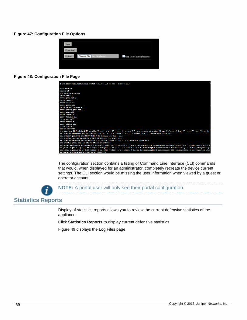
Copyright © 2013, Juniper Networks, Inc 69
Figure 47: Configuration File Options
Figure 48: Configuration File Page
The configuration section contains a listing of Command Line Interface (CLI) commands
that would, when displayed for an administrator, completely recreate the device current
settings. The CLI section would be missing the user information when viewed by a guest or
operator account.
NOTE: A portal user will only see their portal configuration.
Statistics Reports
Display of statistics reports allows you to review the current defensive statistics of the
appliance.
Click Statistics Reports to display current defensive statistics.
Figure 49 displays the Log Files page.

Copyright © 2013, Juniper Networks, Inc 70
Figure 49: Statistics Report Page
These statistics report the activity of the DDoS Secure appliance over the last 24 hours.
Any defense line that comprises of only zero entries is not reported. portal users will only
see data relevant to their portal.
The statistics are broken down into nine sections, and output can cover a day, week or
month depending on the options selected. Some of the sections may not be presented, as
they are not appropriate to the selected options.
Table below provides a summary of the information displayed on the DDoS Secure statistic
report page:
Table 28: DDoS Secure Statics Report Details
FIELD DETAILS
Graphical Summary This section summarizes the Traffic Throughput, the Traffic dropped (Internet Noise,
Black Listed and Attack) and the Traffic Dropped (Attack only).
Packet Drop / Notification
Activity This section summarizes the packet drop activity and reasons why the packets were
dropped, as well as situations that occurred and there was no packet drop activity.
Worst Incidents This section reports any worst incidents tracked over the month, week and day.
Incidents This section reports any incidents that were active for the selected date.

Copyright © 2013, Juniper Networks, Inc 71
Portals These statistics reflect the traffic rates and the counters used for the portal. Any line
containing all zeros in the counters section is not reported.
Table Usage These statistics reflect the usage of different tables with the DDoS Secure appliance
software.
Over time, the History, URLs and Worst Offenders Tables will become 100% full, which
is normal. When the table is full, the least recently used entry is discarded.
Resource Usage These statistics reflect how the appliance is being utilized.
Memory usage is always likely to be high as the underlying OS uses spare memory for
disk caching.
It is possible to look back over the last week and month, previous week and month’s
worth of Statistics by clicking on the appropriate button, or for a specific by selecting the
date and clicking on Date. Up to 60 days worth of information is held, but is dependent
on available disk space.
A copy of this statistical report can be emailed every midnight if required.
General Logs
This allows you to review the log files of the appliance to see what has happened in the
past.
Click General Logs to display log files. Figure 50 displays the DDoS Secure General
Logging page.
Figure 50: DDoS Secure General Logs Page
The log file starts with a date and time entry, followed by a log entry type prefix. The next
entry is appliance, Indeterminate, Multicast, Broadcast, an IP address, a MAC address, or
Incident report identification. The final part of the entry describes why this entry was
logged.
If a Protected IP is unknown, or has not yet been validated, then the entry will be logged
against Indeterminate.

Copyright © 2013, Juniper Networks, Inc 72
BIOS—Indicates an entry from the BIOS System Event Log (SEL).
CLI—User connected or disconnected from the CLI.
Config—Indicates configuration changes. + is added, - is deleted.
Count—Additional information about a condition that has a start reference.
Debug—Debug information.
Disk—Disk Sub-System messages.
End—End of a condition that has a start reference.
Error—Indicates some error condition.
GeoIP—Status change in GeoIP updates from www.maxmind.com.
GUI—User connected or disconnected from the GUI.
Inc't—Indicates information about a specific incident. Clicking on this will take you straight to the Incident information.
Info—Informational information.
Raid—Raid Sub-System messages.
Start—Start of a particular condition.
State—DDoS Secure appliance state change (For Example:. reboot initiated).
Stats—Daily statistics have been generated.
Warn—Indicates some warning condition.
For Worst Offender, the Start: entry is only recorded when the IP address has exceeded
the average error rate as defined under Configure Logging. The End: entry is recorded
when the IP Address is replaced by a new Worst Offender. In addition, the Count: entry
records the different defense types and counts for that specific IP address.
By default, only the first 1Mb of information is displayed with the latest entry at the top. If
there is more information, it is possible to display all the information by clicking on Full List
at the end of the output. This may take some time to download – especially over slower
links.
The display log page has the following options:
Download Logfile—It is possible to download the complete file in compressed format to your local by clicking on Download Logfile, found at the bottom of the log file.
Download HelpDesk Information—By clicking on Download HelpDesk Information (found at the bottom of the log file output), a copy of information suitable for DDoS Secure appliance Support will get downloaded to your local PC for onward forwarding to DDoS Secure appliance Support. This includes the full set of the DDoS Secure appliance log files.
Create Dell DSET Information—By clicking on Create Dell DSET Information (if available, found at the bottom of the log file output), a copy of information suitable for DDoS Secure appliance Support will get built ready for downloading to your local PC for onward forwarding to DDoS Secure appliance Support.

Copyright © 2013, Juniper Networks, Inc 73
NOTE: This may take some time – do not leave the page while this is being processed.
This should not be run on a busy DDoS Secure appliance.
Download Dell DSET Information—By clicking on Download Dell DSET Information (if available, found at the bottom of the log file output), a copy of information suitable for DDoS Secure appliance Support will get downloaded to your local PC for onward forwarding to DDoS Secure appliance Support.
Download Core File—By clicking on Download Core File (if available, found at the bottom of the log file output), a copy of and core files will get downloaded to your local PC for onward forwarding to DDoS Secure appliance Support.
Incident Logs
Display incident page allows you to review the active Incidents tracked by the appliance.
Click Incident Logs to display active Incident information. For an Incident Defense Type to
be displayed here (the default), it has to be enabled in Incident Create Threshold,
configured in Section [Configuring Logging].
Figure 51 displays the tracked incident List page.
Figure 51: Incident Logs
NOTE: Entries that are red font in either the incident log, or the active incidents are incidents that have been over the alert threshold for at least 1 minute.
Incidents can be filtered by Protected IP or Portal by selecting from the pull down list.
Today to bring up a log of incidents that has taken place today.
Date to bring up a log of incidents that have taken place within the specified date range. Only the last 60 days worth of incidents are kept on disk.

Copyright © 2013, Juniper Networks, Inc 74
CSV Display to bring up a comma-separated detail of incidents that have taken place within the specified date range. You can look up a specific incident by entering the incident number, which is in the format yyyymmdd/nnnnnn .
Date and Time hyperlink to drill down to the specific detail of an incident.
Display Incident Details
By hovering the mouse over an IP address, it is possible to roughly determine where the IP
address is.
There are three types of Incident activity – recorded on the 7th line of output.
Packets Dropped—Packets are actually being dropped (unless in Logging mode).
Packets Noted—Packets are actually being noted (as in Logging mode)
Occurred—The situation has been noted this number of times.
Figure 52 displays the specific display incident List page.
Figure 52: Specific Display Incidence Page
Worst Offenders Log File
Click Worst Offender Log to display Worst Offenders. Figure 53 and Figure 54 displays
the Worst offenders page.

Copyright © 2013, Juniper Networks, Inc 75
Figure 53: Worst Offenders Log Page Snippet 1
If an IP address (or Address/NetMask) is entered and the Find IP is clicked, the GUI will
output all entries that it can find in the logs or Incident information.
If a time is defined with a tolerance either side and Find Time is clicked, the all information
referring to the time window is output.
Figure 54: Worst Offenders Log Page Snippet 2
Click Download Logfile (found at the bottom of the log file output), for a copy of the log file
that can be used for post processing on the Worst Offender information. Other download
options are:
Download CSV Logfile.
Download Black-Listed IPs CSV Logfile.
Download Previous Month CSV Logfile.
Download Previous Month Black-Listed IPs CSV Logfile.
Upgrades
Click Upgrade to display the upgrade options
At any point, the Tracked Information (used for calculating CHARM) can be backed up or
restored. The size of the file is large (it can easily exceed 2G), so this process may take
some time and is not normally needed. Figure 55 displays the upgrade software page and
Figure 56 displays the upgrade software via file upload.

Copyright © 2013, Juniper Networks, Inc 76
Figure 55: Upgrade Software Page
To upload the file:
1. Select File Upload and click OK.
Figure 56: Upgrade Software Via File Upload
2. Browse to the previously downloaded file.
3. Click Upgrade.
Figure 57: Confirmation Screen
4. Click OK to continue.
NOTE: It may take some time for your upgrade file to be uploaded. During this period, do not browse away from this screen.

Copyright © 2013, Juniper Networks, Inc 77
Figure 58: Upgrade Confirmation Screen
Figure 59: Upgrade Reboot Screen
The DDoS Secure’s reboot takes 5 to 10 minutes.
Packet Capture
Click Packet Capture to display the Packet Capture options.
It is possible to record up to 9 distinct packet capture files. If there has not been any
recording, all of the recording file slots (accessible via the pull-down menu) will be labeled
New and the Start Recording button will be displayed.
Figure 60 displays the new packet capture page.

Copyright © 2013, Juniper Networks, Inc 78
Figure 60: New Packet Capture Page
If a recording does exist, it will be identified by its timestamp in one of the recording file
slots. Select a recording by choosing its entry in the pull-down menu. A table will display
statistics associated with that file. . See Figure 61.
Click Start Recording, a new recording will be started that will overwrite any existing recording in this file slot. It is possible to restrict the IP addresses that are recorded by specifying an IP address, or a network with a network mask. Setting such a restriction does not strip out all non-masked traffic, as IP addresses may not be easily determined (to minimize performance overhead) at the time of recording. It is also possible to enable a continuous recording loop by ensuring that the Continuous check box has been selected. In continuous mode a new recording is started in the next recording slot when the current recording slot becomes full or the system is restarted. Once the last record slot 9 has been used the system restarts the continuous record loop with slot 1.

Copyright © 2013, Juniper Networks, Inc 79
Caution: When recording, there is a performance overhead (about 10%) (CPU usage and disk write activity) that may cause your DDoS Secure appliance to drop a few packets, normally when the DDoS Secure appliance is heavily loaded, especially at the point of starting a new recording.
Figure 61: Existing Packet Capture Page
Packet Capture Recording Termination
At any time, click Stop Recording to stop recording. The recording will automatically stop
when the Recording Size reaches 500 MB, unless running in continuous recording mode,
when the next recording slot will be used.
Before displaying any recorded data, it is possible to select a specific network address,
protocol, port or defense type, or any combination of these types in order to reduce the

Copyright © 2013, Juniper Networks, Inc 80
displayed data. Furthermore, Filter syntax (based on BPF (as used by tcpdump)) can be
specified for further data reduction.
Packet Capture Display
Before displaying any recorded data, it is possible to select a specific network address,
protocol, port or defense type, or any combination of these types in order to reduce the
displayed data. Furthermore, Filter syntax (based on BPF (as used by tcpdump)) can be
specified for further data reduction
NOTE: If the bpf filter is being used, and the DDoS Secure appliance is sitting on a VLAN / MPLS trunk, then the appropriate VLAN /MPLS keywords need to be used.
It is possible to enable the output of MAC address information for the packets displayed,
select whether to show only inbound or outbound packets and decode the packets that
contain State information that is being shared between DDoS Secure appliances.
Having entered any of the optional data reduction options, click on Display Data to review
the recording. This step can be performed even on a recording that is still in progress.
Figure 62 displays the packet capture display page.
Figure 62: Packet Capture Display Page
The records are color coded as follows:-
Gray—Traffic seen by DDoS Secure appliance, but not appropriate to pass through, with reason given.
Amber—Indicates that packets are dropped.

Copyright © 2013, Juniper Networks, Inc 81
Blue—Indicates that packets are generated and sessions are informed.
The columns are generally broken out as:
| Time | Protocol | Src IP| Src Port | Direction | Dest IP | Dst Port | Length| Fragment ID |.
For TCP, this continues as:- |TCP Flags | TCP State | Sequence numbers| Window Size.
For ICMP, this can continue as:- |Sequence numbers.|
For fragmented packets, H: is start fragment, M: is middle fragment, T: is tail fragment and
O: is starting offset.
HB is the Heart Beat protocol that DDoS Secure appliance uses for Fail Over
synchronization.
Figure 63 displays the packet capture display column page.
Figure 63: Packet Capture Display Column Page
Slide to right to get Drop Reason.
Some of the fields within a line may be color coded to indicate duplicate or out of order
packets (blue), missing packets (red), updating SACKs (green) and MAC address on the
wrong side (red).
If recordings are continuous, then the decode logic will continue into the next recording if
appropriate.
Packet Capture Save Off the DDoS Secure Appliance
Click Download Recording and a copy of that recording will be downloaded onto your PC
for onward transmission to a DDoS Secure appliance Engineer for analysis. It is possible
to download this recording in native format, or in pcap format (as used by tcpdump,
ethereal, and so on.). If downloaded in pcap format, a lot of the recording information
(such as why a packet was dropped) is lost and DDoS Secure appliance staff will always
want a copy of the native format.
If a USB disc drive is plugged into the DDoS Secure appliance (the USB drive has to have
a formatted file system), this will be detected by the Record Replay GUI page and an
additional button Copy Recording # xx to USB Drive is displayed. These recordings are

Copyright © 2013, Juniper Networks, Inc 82
always copied off in DDoS Secure appliance Native format. If there is an error when doing
the recording copy, then this will be displayed. The most likely cause for this will be
insufficient disk space on the external USB drive.
Figure 64 displays the packet capture download recording page.
Figure 64: Packet Capture Download Recording Page
Click Download Recording #1.
Figure 65 displays the packet capture download recording page.
Figure 65: Packet Capture Recording Download Page
Click on which format output version you require.
Figure 66 displays the packet capture download recording confirmation page.

Copyright © 2013, Juniper Networks, Inc 83
Figure 66: Packet Capture Recording Download Confirmation Page
Click OK
Shutdown DDoS Secure Appliance
Click Shutdown to shutdown your DDoS Secure appliance. Figure 67 displays the shut
down page.
Figure 67: Shut Down Page
There are five options with an optional sixth option if the DDoS Secure appliance is running
as Active in a Fail-Over relationship.
Shutdown DDoS Secure Appliance and Poweroff—The appliance may be powered off using this control. All file systems will be updated safely using this method. To restart, the appliance will require a power cycle.
NOTE: This option not available when DDoS Secure appliance is running as an Application on a third-party hardware platform.
Shutdown DDoS Secure appliance and Reboot—During normal operation it should not be necessary to reboot the DDoS Secure appliance. However all file systems will be updated safely using this method and the appliance will reboot automatically, taking around five minutes.
NOTE: This option not available when DDoS Secure appliance is running as an Application on a third-party hardware platform.
Shutdown DDoS Secure appliance Engine—This will stop the DDoS Secure appliance Engine, but leave the GUI running. To restart the DDoS Secure appliance engine, click on Restart DDoS Secure appliance Engine.
NOTE: If the management access to the DDoS Secure appliance is though the DDoS Secure appliance, if you do not have a HA system, or a fail-safe card, you will lose access to the DDoS Secure appliance.

Copyright © 2013, Juniper Networks, Inc 84
Shutdown DDoS Secure appliance Engine and Restart—This will stop and then automatically restart the DDoS Secure appliance Engine. This is not the same as doing a Shutdown DDoS Secure appliance and Reboot, which completely shuts down the operating system and then completely reboots the appliance from scratch.
Shutdown DDoS Secure appliance Engine, Clear State and Restart—This will stop and then automatically restart the DDoS Secure appliance Engine. All State information is cleared out providing a clean start for the DDoS Secure appliance. This is not the same as doing a Shutdown DDoS Secure appliance and Reboot, which completely shuts down the operating system and then completely reboots the appliance from scratch.
Go Standby—This option is only displayed when the DDoS Secure appliance is the Active DDoS Secure appliance in a Fail-Over Cluster. This option will cause the DDoS Secure appliance to drop out of Active State so that a partner in the Cluster will take over the Active role.

Copyright © 2013, Juniper Networks, Inc 85
CHAPTER 4
STATISTICAL DISPLAYS
This chapter describes the statistical displays of the appliance protected traffic can be seen
using the Summary Dashboard display button.
Summary Dashboard
Click Summary Dashboard to display summary dashboard details.
Summary Dashboard contains six tables or information / graphs summarizing the traffic
passing throught Junos DDoS Secure appliance. Figure 68 displays summary dashboard
page.
Figure 68: Summary Dashboard Page
Table 29: Summary Dashboard Details
FIELD DETAILS
Traffic Monitor This shows your peak traffic usage (inbound and outbound) over the selected period
(default is 24 hrs).
Load Status This reports on how busy the Junos DDoS Secure engine is.

Copyright © 2013, Juniper Networks, Inc 86
Attack Status This reports on how aggressively the Junos DDoS Secure appliance is dropping
traffic to defend the appropriate resources.
Good Traffic This reports on the distribution of where good traffic is coming from.
Bad Traffic This reports on the distribution of where the bad traffic is coming from.
Protected Performance This reports on how busy a protected IP is from an aggregated Charm perspective,
and what the average traffic to and from the IP is.
Status Information
Click Status Information to display status information. Figure 69 displays the status
information page.
Figure 69: Status Information Page
The status info display is the primary information source for DDoS Secure appliance and is
useful both during attacks and in normal operation. All information comprises of current
values and peak value. Peak values represent data since the last reboot, or the time of the
last Reset. If an individual cell is clicked, this displays the pop up graph menu.
If an entry turns orange, or red, then packets are being dropped based on Charm values.
Different protected IPs or portals can be monitored by the choosing the viewing option at
the top of the screen.

Copyright © 2013, Juniper Networks, Inc 87
If Reset Status Info Peak Values is clicked, then all the peak values will be reset back to
zero.
Table 30: Status Information Details
FIELD DETAILS
Summary Information
Data Rate (bps) This is the average speed of data processed for the specified protected IP or appliance.
Packet Rate (/s) This is the average packets per second processed for the specified protected IP or
appliance.
Protected Information
Backlog Queue This is the number of partially open TCP connections for the specified protected IP or
appliance.
IP Latency (usecs) This is the rolling average protected IP response times to a new connection request.
Open Connections This is the number of TCP connections for the specified protected IP or appliance.
Connection Requests (/s)
This is the number of TCP connection requests for the specified protected IP or appliance.
Active HTTP GETs This is the number of HTTP page requests being processed by the protected IP, and
indicates the page request (GET, HEAD or POST) has been sent, but not yet responded
to.
Overloaded IP (/s) This is the rate at which the DDoS Secure appliance has decided that an IP address is
overloaded.
Protocol Bit Rate
TCP Rate (bps) This is the averaged speed of TCP data processed for the specified protected IP or
appliance.
UDP Rate (bps) This is the averaged speed of UDP data processed for the specified protected IP or
appliance.
ICMP Rate (bps) This is the averaged speed of ICMP data processed for the specified protected IP or
appliance.
Other Rate (bps) This is the averaged speed of Other-IP data processed for the specified protected IP or
appliance.
Protocol Packet Rate

Copyright © 2013, Juniper Networks, Inc 88
TCP Rate (pps) This is the averaged packets per second for TCP processed for the specified protected IP
or appliance.
UDP Rate (pps) This is the averaged packets per second for UDP processed for the specified protected IP
or appliance.
ICMP Rate (pps) This is the averaged packets per second for ICMP processed for the specified protected
IP or appliance.
Other-IP Rate (pps) This is the averaged packets per second for Other-IP processed for the specified protected
IP or appliance.
Packet Size Information
Packet (Small) Rate (/s) This is the averaged packets (256 bytes or less) per second processed for the specified
protected IP or appliance. This includes packets that may have been dropped.
Packet (Medium) Rate (/s)
This is the averaged packets (1024 bytes or less, but greater than 256 bytes) per second
processed for the specified protected IP or appliance. This includes packets that may
have been dropped
Packet (Large) Rate (/s) This is the averaged packets (greater than 1024 bytes) per second processed for the
specified protected IP or appliance. This includes packets that may have been dropped.
Drop Information
Drop Rate (bps) This is the averaged rate of data dropped by the appliance for the specified protected IP,
or appliance.
Packets Dropped (/s) This is the averaged packets per second dropped for the specified protected IP, or
appliance.
Charm Dropped (pps) This is the averaged packets per second that DDoS Secure appliance has dropped by
heuristic detection.
Charm Dropped (bps) This is the averaged rate of data that DDoS Secure appliance has dropped by heuristic
detection.
Filtered Bandwidth (%) This is a representation of the dropped bandwidth divided by the actual bandwidth. It must
be noted that on idle connections, this percentage is likely to be large as most of the traffic
will just be noise.
Traffic Limiting
Bandwidth (/s) The packets per second that have been dropped due to the bandwidth being greater than
the defined bandwidth value or filter set for the portals; or the maximum bandwidth for the
appliance has been breached.

Copyright © 2013, Juniper Networks, Inc 89
Packet Rate (/s) The number of packets per second which have been dropped due to portal or filter
configuration on the Packet Rate limiting settings being breached.
Blocked Protocol (/s) The number of packets per second that DDoS Secure appliance has dropped due to
either a protocol not being enabled in a filter, or an IP address has been black-listed.
Unknown Session (/s) When packets are seen which do not have entries in the DDoS Secure appliance state
table and are not starting a connection or are in the state table but the sequence numbers
do not match.
Protocol Attack Rate This is the rate of packets per second the DDoS Secure appliance has classified attack
traffic, for the following:
IP Attack (/s)
TCP Attack (/s)
UDP Attack (/s)
ICMP Attack (/s)
Other-IP Attack (/s)
Fragment Attack (/s)
Malformed Packet Rate The packet rate detected and classified as following:
Bad IP Packet (/s)
Bad TCP Packet (/s)
Bad UDP Packet (/s)
Bad ICMP Packet (/s)
Bad O-IP Packet (/s)
Other line items These are counters for occurrences per second that potentially cause a red light to be
turned on in the right hand pane.

Copyright © 2013, Juniper Networks, Inc 90
Protected Information
Click Protected Information to display Protected IP Information.
Figure 70 displays the protected information.
Figure 70: Protected Information Page
By clicking the + in front of the portal name, the Protected IPs associated with the portal are
expanded out.
NOTE: If a specific portal or IP address is selected in the Viewing : pull down (top right), then only the associated portal will be available for review.
The Central Pane describes the determined protected IPs, as well as the respective traffic
rates. Each transaction has twenty-five parameters. The entries that have action cells will
bring up graphs of previous data. The respective columns can be sorted by clicking on the
appropriate column head.
For the columns that have 4 entries, these are current, peak, suggested value to use for
CHARM and the last entry is the current configured value for that parameter. If the last
entry is in a blue font then this entry is auto- configured and the displayed value shows the
currently determined value. If third entry font is in red, then this is a suggested
configuration value that DDoS Secure appliance has determined to be suitable.
Reconfigure the protected IP with this value and observe whether DDoS Secure appliance
suggests another iteration of configuration.
If any entry is reverse video-d in orange then packets are being dropped, as their CHARM
score is too low. If the entry is reverse video-d in red, then potentially high CHARM value
packets are being dropped.
If you click Reset Protected Statistics, all the peak values will be reset back to zero.
NOTE: The value in Backlog Queue can rise above the configured defense threshold. It may even fail to turn orange such situations. This can occur because the defense threshold is configured on a per a port basis, the value displayed in the table is the total backlog for all TCP connection attempts to the protected IP, for all the TCP ports.

Copyright © 2013, Juniper Networks, Inc 91
The value in the Backlog Queue does not include requests to ports that are not open or not responding, or include SYN requests that are let through in logging mode that should have been dropped.
Table below provides the parameters of the protected information page details.
Table 31: Protected Information Page Details
FIELD DETAILS
IP Address The IP address or IP address tree for drilling down.
Slow Syn This is a count of SYN requests that have taken more than 5 seconds to respond to.
Backlog This is the current/peak/configured number of partially open TCP connections.
Open Connections This is the current/peak/configured number of open TCP connections.
Connection Requests This is the current/peak/configured number of TCP connection requests per sec.
Slow Get This is a count of GET requests that have taken more than 5 seconds to respond to.
Gets This is the current/peak/configured number of HTTP page requests being processed.
In Drop (Pkts/s) This is the current/peak number of packets to the Protected IP dropped per second.
In (Pkts/s) This is the current/peak number of packets to the Protected IP in packets per second.
In (Bits/s) This is the current/peak speed of data to the Protected IP in bits per second.
Out Drop (Pkts/s) This is the current/peak number of packets from the Protected IP dropped per second.
Out (Pkts/s) This is the current/peak speed of data from the Protected IP in packets per second.
Out (Bits/s) This is the current/peak speed of data from the Protected IP in bits per second.
In TCP (Pkts/s) This is the current/peak TCP number of packets to the Protected IP in packets per
second.
In TCP (Bits/s) This is the current/peak TCP speed of data to the Protected IP in bits per second.
In UDP (Pkts/s) This is the current/peak UDP number of packets to the Protected IP in packets per
second.
In UDP (Bits/s) This is the current/peak UDP speed of data to the Protected IP in bits per second.
In ICMP (Pkts/s) This is the current/peak ICMP number of packets to the Protected IP in packets per
second.

Copyright © 2013, Juniper Networks, Inc 92
In (TCP) Number of inbound initiated TCP sessions.
Out (TCP) Number of outbound initiated TCP sessions.
Out (UDP) Number of outbound initiated UDP sessions.
Out (ICMP) Number of outbound initiated ICMP sessions.
Out (Other) Number of outbound initiated Other IP sessions.
Out (Fragment) Number of outbound initiated Fragment tracking sessions.
Live Incidents
Click Live Incidents to display Live Incident information. This allows you to review the
active Incidents tracked by the appliance.
For an Incident Defense Type to be shown here (the default), it has to be enabled in
Incident Create Threshold, configured in [Configuring Logging].
Entries in red highlight Incident activity that has been over the Alert threshold for at least 1
minute.
This allows you to review live incidents tracked by the appliance. . Figure 71 shows the list
of live incidents, to view more information about a particular incident click the associated
row.
Figure 71: Live Incidents List
Figure 72 displays the live incidents page with highlighted screens.

Copyright © 2013, Juniper Networks, Inc 93
Figure 72: Live Incidents Page
Green Screen—Incidents screen (minimized version than on page load)
Blue Screen—Summary of specific incident
Purple Screen—Graph of specific attack vector
Yellow Screen—List source IPs involved in incident, (max 20 individual IPs)
NOTE Initial incident screen is shown in green. The other screens appear when specific incident selected.
Worst Offenders
Click Worst Offenders to display Worst offender
The Central Pane shows real time status of the worst offending IP addresses, along with
the reason why. By clicking on the head of a column, the output is sorted by this column,
with the triangle indicator showing the sort direction.
Figure 73 displays the worst offenders page.
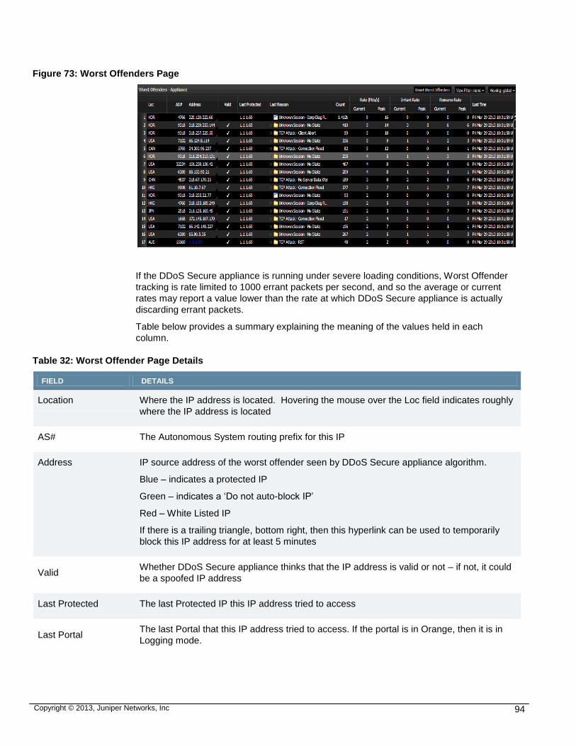
Copyright © 2013, Juniper Networks, Inc 94
Figure 73: Worst Offenders Page
If the DDoS Secure appliance is running under severe loading conditions, Worst Offender
tracking is rate limited to 1000 errant packets per second, and so the average or current
rates may report a value lower than the rate at which DDoS Secure appliance is actually
discarding errant packets.
Table below provides a summary explaining the meaning of the values held in each
column.
Table 32: Worst Offender Page Details
FIELD DETAILS
Location Where the IP address is located. Hovering the mouse over the Loc field indicates roughly
where the IP address is located
AS# The Autonomous System routing prefix for this IP
Address IP source address of the worst offender seen by DDoS Secure appliance algorithm.
Blue – indicates a protected IP
Green – indicates a ‘Do not auto-block IP’
Red – White Listed IP
If there is a trailing triangle, bottom right, then this hyperlink can be used to temporarily
block this IP address for at least 5 minutes
Valid Whether DDoS Secure appliance thinks that the IP address is valid or not – if not, it could
be a spoofed IP address
Last Protected The last Protected IP this IP address tried to access
Last Portal The last Portal that this IP address tried to access. If the portal is in Orange, then it is in
Logging mode.

Copyright © 2013, Juniper Networks, Inc 95
Last Reason The last reason why this IP address was determined to be a “worst offender”
Count The number of times this IP address has been identified as an attacker
Rate (Pkts/s) The current / peak packet rates per second
Irritant Rate The current / peak packet rates per second of irritant attacks
Resource Usage Rate The current / peak packet rates per second of resource consuming attacks
Last Time The last time this IP address was determined to be a “worst offender”
If the Last Reason column shows a folder icon, it can be expanded to drill down to the
breakout of the different types of defense invoked against this IP as shown in Figure 74.
Figure 74: Last Reason Expand Page
If Reset Worst Offenders is clicked (top right hand side of worst offenders table), then all
the Worst Offender entries will be removed.
To view logs of past worst offenders see [Error! Reference source not found.].
To temporary black list a worst offender, select the select the IP and click the triangle at the
bottom right of the cell. This will display the Black-List dialog box which must be clicked to
confirm the action.
Once completed, the following confirmation will appear:
Figure 75: Last Reason Confirmation Page

Copyright © 2013, Juniper Networks, Inc 96
Temporarily Black Listed
Click the Temporarily Black Listed option to display the Temporarily blacklisted
information.
Figure 76 displays the tracked information.
Figure 76: IP Temporarily Black Listed Information Page
Table 33: Temporarily Black Listed Information Page Details
FIELD DETAILS
Location Where the IP address is located. Hovering the mouse over the Loc field indicates
roughly where the IP address is located
AS# The Autonomous System routing prefix for this IP
Address IP address of the worst offender seen by DDoS Secure appliance algorithm
Valid Whether DDoS Secure appliance thinks that the IP address is valid or not (i.e. spoofed)
Last Protected The last Protected IP this IP address tried to access
Last Portal The last Portal this IP address tried to access. If the portal is in Orange, then it is in
Logging mode.
Rate (Pkts/s) The current / peak packet rates per second
Speed (Bits/s) The current / peak bit rates per second
Count The number of packets dropped from this IP address
Last Time The last time this IP address was blocked
Reason The reason why this IP address was temporarily black listed

Copyright © 2013, Juniper Networks, Inc 97
To manually remove an IP from the Temporary Black List, select the IP and click the
triangle at the bottom right of the cell. This will display the un-black-list dialog box which
must be clicked to confirm the action. The confirmation screen appears:
Figure 77: Black List Removal Confirmation
If Purge Black-List is clicked top row towards the right, then all IP addresses are removed
from the Auto Black-List List.
IP addresses are automatically removed from the Auto Black-List IP list when DDoS
Secure appliance determines that it is safe to do this. This is usually after 5 minutes of in-
activity for this IP.
IP Tracked Information
Click IP Tracked Info to display tracked information.
Figure 78 displays the tracked information.
Figure 78: IP Tracked Information Page
The Central Pane outputs some of the IP information used for CHARM calculations. Each
entry has twenty-one parameters.
Table below provides the parameters of the tracked information page details.

Copyright © 2013, Juniper Networks, Inc 98
Table 34: Tracked Information Page Details
FIELD DETAILS
Location The GeoIP location of the IP address.
AS# The Autonomous System routing prefix for this IP.
IP Address The IP address. If the address is in Orange, then this IP has been troublesome. If this IP
is in Red, then this IP address has been black-listed..
Last Protected Last Protected IP address that this IP tried to get to.
Backlog Queue This is the number of partially open TCP connections.
Half Conn This is the number of connections that have completed the three way handshake, but no
data has been transferred yet.
Connections This is the number of open (active) TCP connections.
Errors This is the error rate of the IP.
Bit Rate This is the rolling average speed of data to / from the IP in bits per second.
GET Rate The number of GETs requested by the IP per second. This number is scaled up when
tracking specific URLs that are matched.
BL IP is defined in the Black List.
WL IP is defined in the White List.
WN IP is defined in the White List (No Logging).
PL IP is defined as a preferred client (CHARM boost).
DL IP is defined as always having Default CHARM.
CA IP Address overrides any Country Blocking.
NB IP address can never be auto-blocked.
MP IP address is defined as a Mega-Proxy
P IP address is detected as a proxy server.
F IP address is currently being filtered by a protected IP.
Last Seen This is the time that traffic was seen to / from this IP address.

Copyright © 2013, Juniper Networks, Inc 99
Country Usage Information
Click Country Usage Info to display Usage Information.
Figure 79:Country Usage Information
The Central Pane shows real time status of traffic through the appliance, based on Country
of origin. By clicking on the head of a column, the rows can be sorted.
Table below gives a summary explaining the meaning of the values held in each column.
Table 35: Country Usage Information Page Details
FIELD DETAILS
Country Country of origin. Hovering the mouse over the Country indicates the Country Code. If this entry
is orange, then this country is black-listed. If this entry is orange, then this country is partially
blocked by a filter.
Clients The current / peak number of history table entries for this Country.
TCP The current / peak number of TCP table entries for this Country.
UDP The current / peak number of UDP table entries for this Country.
ICMP The current / peak number of ICMP table entries for this Country.
Other The current / peak number of Other IP table entries for this Country.
Frag The current / peak number of Fragment table entries for this Country.
Drop (Pkts/s) The current / peak number of packets per second dropped from this Country.
Inbound (Pkts/s) The current / peak number of packets per second from this Country.
Inbound (Bits/s) The current / peak data rate per second from this Country.
Outbound (Pkts/s) The current / peak number of packets per second to this Country.

Copyright © 2013, Juniper Networks, Inc 100
Outbound (Bits/s) The current / peak data rate per second to this Country.
Only Countries that have any activity are reported.
Clicking on Reset Country Usage Statistics will reset all the peak values used to build the
table.
An orange cell represents a black listed country.
To black list a country, click the country cell to bring up the Black-List menu then select
Black-List, alternatively unblock a blacklisted country shown in orange following the same
process.
Figure 80: Black List Menu Options
TCP Information
Click TCP Information to display TCP information.
Figure 81 displays the real time status of the TCP connections through DDoS Secure
appliance.

Copyright © 2013, Juniper Networks, Inc 101
Figure 81: TCP Information Options
By selecting the TCP States dropdown (highlighted in blue above), this will filter the TCP
Information to the selected TCP State type.
If any entry is highlighted in orange then packets are being dropped, as their CHARM score
is too low. If the entry is red, then high CHARM value packets are being dropped.
Table below provides a summary explaining the meaning of the values held in each
column.
Table 36: TCP Information Page Details
FIELD DETAILS
Vlan/MPLS The outer level Vlan or MPLS tag for this session
Internet Location Where the IP address is located. Hovering the mouse over the Location field indicates roughly
where the IP address is located.
Internet AS# The Autonomous System routing prefix for this IP
Internet IP IP Address of the Internet side of the connection
Internet Port Port of the Internet side of the connection
X-Forwarded-For
Location
Location for Internet traffic coming via a Proxy / CDN server

Copyright © 2013, Juniper Networks, Inc 102
X-Forwarded-For AS# The Autonomous System routing prefix for Internet traffic coming via a Proxy / CDN server
X-Forwarded-For IP IP address of the Internet traffic coming via a Proxy / CDN server
Dir Direction of initiated session
Protected IP IP Address of the Protected side of the connection
Protected Port Port of the Protected side of the connection
Protected Portal The Portal the protected IP resides in. If the portal is in Orange, then it is in Logging mode.
Inbound Bytes The number of data bytes received from the Client.
Inbound Pkts The number of packets received from the Client.
Outbound Bytes The number of data bytes received from the Protected IP.
Outbound Pkts The number of packets received from the Protected IP.
Active Time in seconds since the first SYN of the connection.
State State of connection –This entry is in red if there is DDoS Secure appliance TCP keep-alive
probing.
The background for each line can be color coded as follows:
Green—Entry has expired and is waiting for deletion
Orange —Entry created due to a routing redirect packet bounce
Yellow —Pseudo Connection that would normally have been dropped, but the DDoS Secure appliance is in logging mode for this particular connection.
Light blue font—State information learnt from another DDoS Secure appliance.
UDP Information
Click UDP Information to display UDP information.
Figure 82 displays real time status of the UDP transactions through DDoS Secure
appliance.
Figure 82: UDP Information Page
Table below provides the parameters of the UDP information page details.

Copyright © 2013, Juniper Networks, Inc 103
Table 37: UDP Information Page Details
FIELD DETAILS
Vlan/MPLS The outer level Vlan or MPLS tag for this session
Internet Location Where the IP address is located. Hovering the mouse over the Location field indicates roughly where the
IP address is located.
Internet AS# The Autonomous System routing prefix for this IP
Internet IP IP Address of the Internet side of the connection
Internet Port Port of the Internet side of the connection
Dir Direction of initiated session
Protected IP IP Address of the Protected side of the connection
Protected Port Port of the Protected side of the connection
Protected Portal The Portal the protected IP resides in. If the portal is in Orange, then it is in Logging mode.
Inbound Bytes The number of data bytes received from the Client
Inbound Pkts The number of packets received from the Client
Outbound Bytes The number of data bytes received from the Protected IP
Outbound Pkts The number of packets received from the Protected IP
Active Time in seconds since the first SYN of the connection.
The background for each line can be color coded as follows :
Green—Entry has expired and is waiting for deletion.
Orange—Entry created due to a routing redirect packet bounce.
Yellow—Pseudo Connection that would normally have been dropped, but the DDoS Secure appliance is in logging mode for this particular connection.
Light blue font—State information learnt from another DDoS Secure appliance.
ICMP Information
Click ICMP Information to display ICMP information.
Figure 83 displays the real time status of the ICMP transactions through DDoS Secure
appliance.

Copyright © 2013, Juniper Networks, Inc 104
Figure 83: ICMP Information Page
Table below provides the parameters of the ICMP information page details
Table 38: ICMP Information Page Details
FIELD DETAILS
Vlan/MPLS The outer level Vlan or MPLS tag for this session
Internet Location Where the IP address is located. Hovering the mouse over the Location field indicates roughly
where the IP address is located.
Internet AS# The Autonomous System routing prefix for this IP
Internet IP IP Address of the Internet side of the connection
Dir Direction of initiated session
Protected IP IP Address of the Protected side of the connection
Type:Code ICMP type / code
Protected Portal The Portal the protected IP resides in. If the portal is in Orange, then it is in Logging mode.
Inbound Bytes The number of data bytes received from the Client.
Inbound Pkts The number of packets received from the Client.
Outbound Bytes The number of data bytes received from the Protected IP.
Outbound Pkts The number of packets received from the Protected IP.
Active Time in seconds since the first SYN of the connection.
The background for each line can be color coded as follows:
Green—Entry has expired and is waiting for deletion.
Orange—Entry created due to a routing redirect packet bounce.
Yellow—Pseudo Connection that would normally have been dropped, but the DDoS Secure appliance is in logging mode for this particular connection.

Copyright © 2013, Juniper Networks, Inc 105
Light blue font—State information learnt from another DDoS Secure appliance.
Other IP Information
Other IP protocol information contains information on protocols not listed in the above
protocol specific displays. These should be monitored for unusual or unexpected traffic.
Click Other Information to display other IP Protocol information.
Figure 84 displays the real time status of the other IP protocol transactions through DDoS
Secure appliance.
Figure 84: Other IP Protocol Information Page
Table below provides the parameters of the other IP information page details.
Table 39: Other IP Information Page Details
FIELD DETAILS
Vlan/MPLS The VLAN, or MPLS label associated with this connection
Internet Location Where the IP address is located. Hovering the mouse over the Location field indicates
roughly where the IP address is located.
Internet AS# The Autonomous System routing prefix for this IP.
Internet IP IP Address of the Internet side of the connection.
Dir Direction of initiated session.
Protected IP IP Address of the Protected side of the connection.
Proto IP Protocol in use.
Protected Portal The Portal the protected IP resides in. If the portal is in Orange, then it is in Logging
mode.
Inbound Bytes The number of data bytes received from the Client.
Inbound Pkts The number of packets received from the Client.
Outbound Bytes The number of data bytes received from the Protected IP.
Outbound Pkts The number of packets received from the Protected IP.

Copyright © 2013, Juniper Networks, Inc 106
Active Time in seconds since the first SYN of the connection.
The background for each line can be color coded as follows:
Green—Entry has expired and is waiting for deletion.
Orange—Entry created due to a routing redirect packet bounce.
Yellow—Pseudo Connection that would normally have been dropped, but the DDoS Secure appliance is in logging mode for this particular connection.
Light blue font—State information learnt from another DDoS Secure appliance.
Details of Protocol Numbers can be found at:
http://www.iana.org/assignments/protocol-numbers/protocol-numbers.xml#protocol-numbers-1
Fragment Information
Click Fragment Information to display Fragment Information.
The Central Pane shows real time status of currently active, valid fragmented packets.
Each transaction has fourteen parameters. The yellow entries record fragments that are
dropped, but are tracked so that other fragments of the same sequence can be dropped.
Figure 85 displays the fragmentation information.
Figure 85: Fragmentation Information Page
Table below provides the parameters of the fragment information page details.
Table 40: Fragment Information Page Details
FIELD DETAILS
Vlan/MPLS The VLAN, or MPLS label associated with this connection
Internet Location Where the IP address is located. Hovering the mouse over the Location field indicates
roughly where the IP address is located.
Internet AS# The Autonomous System routing prefix for this IP
Internet IP IP Address of the Internet side of the connection
Dir Direction of initiated session
Protected IP IP Address of the Protected side of the connection

Copyright © 2013, Juniper Networks, Inc 107
ID The Fragment identification, followed by which part(s) of the sequence seen.
H – Head, M – Middle and T – Tail.
Proto The IP Protocol of the fragment
Port Port (if known) for TCP/UDP
Protected Portal The Portal the protected IP resides in. If the portal is in Orange, then it is in Logging
mode.
Inbound Bytes The number of data bytes received from the Client.
Inbound Pkts The number of packets received from the Client.
Outbound Bytes The number of data bytes received from the Protected IP.
Outbound Pkts The number of packets received from the Protected IP.
Active Time in seconds since the first SYN of the connection.
The background for each line can be color coded as follows:
Green—Entry has expired and is waiting for deletion
Orange—Entry created due to a routing redirect packet bounce
Yellow—Pseudo Connection that would normally have been dropped, but the DDoS Secure appliance is in logging mode for this particular connection.
Light blue font—State information learnt from another DDoS Secure appliance.
URL Information
Click URL Information to display URL Information.
The Central Pane shows real time status of the most active inbound 32K URLs tracked
through the appliance and each row represents one of these URLs.
Click Reset URL Peak Values to reset the current list.
Click URL Filter to filter on the URL [ + Parameters] column. This is additional to the View
Filter which will filter IPs/AS# and Loc.
Figure 86 displays the URL information.
Figure 86: URL Information Page
Table below provides the parameters of the URL information page details.

Copyright © 2013, Juniper Networks, Inc 108
Table 41: URL Information Page Details
FIELD DETAILS
Rate The current / peak number of URL hits for this URL.
Pending The number of outstanding requests to be responded to
Response Time This give the minimum, last and peak response times to the URL request.
Peak Time Time of the peak response time.
Last IP The last IP to request this URL.
Response The last HTTP response code for this URL
Protected IP The Protected IP the URL was requested on..
Protected Portal The Portal the protected IP resides in. If the portal is in Orange, then it is in Logging mode.
Mode The type of request (GET/HEAD/POST).
URL The actual URL including the domain. If this URL is red, then this URL is being specifically
tracked.
Reset Resets the peak values of the current list of URLs.
Full List All the active URLs to be displayed. The Center Pane will not refresh.
Refresh Page refreshes.
Only URLs that have any activity are reported.
Clicking a URL will give you the option of tracking, or untracking this URL. It is possible to
tune this further via the CLI. If a URL is being tracked, all IP addresses requesting this
URL will get a lower CHARM value. If an IP address is aggressively accessing this tracked
URL, then the IP address will get a very low CHARM value and is likely to be dropped if the
Protected IP is limiting GET requests. Figure 87 displays the URL information options.
Figure 87: URL Information Options
Entering a value in URL Filter: (top line) and <enter> to match specific URLs for output..

Copyright © 2013, Juniper Networks, Inc 109
More information on HTTP Response Codes can be found at:
http://www.iana.org/assignments/http-status-codes/http-status-codes.xml#http-status-codes-1
DNS Information
Click DNS Information to display DNS Information.
Figure 88 displays the DNS information.
Figure 88: DNS Information Page
The Central Pane shows real time status of the most active inbound 32768 DNS requests
tracked through the appliance. Each row represents one of these DNS requests.
Table below provides the parameters of the DNS information page details.
Table 42: DNS Information Page Details
FIELD DETAILS
Rate The current / peak number of DNS hits for this DNS query.
Inbound (bps) The current / peak inbound rate for this DNS query.
Outbound (bps) The current / peak outbound response rate for this DNS query.
Pending Number of DNS queries not yet responded to
Response Time This give the minimum, last and peak response times for the DNS query.
Peak Time Time of the peak response time.
Last IP The last IP to request this DNS query.
Response DNS query response. If blank, the DNS server has not responded.
Protected IP The Protected IP the DNS was sent to. If looking at a particular protected IP, then only
this protected IP DNS queries will be shown.
Protected Portal The Portal the protected IP resides in. If the portal is in Orange, then it is in Logging
mode.
Name Type The DNY query (including implicit trailing period followed by the query type. If this DNS
query is in red, then this DNS query is being specifically tracked.

Copyright © 2013, Juniper Networks, Inc 110
Only DNS queries that have any activity are reported.
Clicking on a DNS query will give you the option of black-listing, or un-black-listing this DNS
query. It is possible to tune this further via the CLI. If a DNS query is being black-listed,
the DNS query packet will get dropped. If a DNS query is being tracked, all IP addresses
requesting this DNS query will get a lower CHARM value. If an IP address is aggressively
accessing this tracked DNS query, then the IP address will get a very low CHARM value
and is likely to be dropped if the Protected IP is limiting GET requests.
Enter a value in DNS Mask followed by <enter> for the output the DNS entries that match
the supplied Mask.
SIP Information
The Central Pane shows real time status of the most active inbound 32K SIP REGISTER
and INVITE requests tracked through the appliance. Each row represents one of these
requests. By clicking on the head of a column, the output of rows is sorted by this column.
Figure 89 displays the SIP information.
Figure 89: SIP Information Page
Table below provides a summary explaining the meaning of the values held in each
column.
Table 43: SIP Information Page Details
FIELD DETAILS
Rate The current / peak number of requests for this SIP URI.
Pending Number of SIP queries not yet responded to
Response Time This gives the minimum, last and peak response times for the SIP request.
Peak Time Time of the peak response time.
Last IP The last IP to send this request.
Response The last response code for this request. No code indicates that the server has yet to issue a
response.
Protected IP The Protected IP the request was sent to.
Protected Portal The Portal the protected IP resides in. If the portal is in Orange, then it is in Logging mode.

Copyright © 2013, Juniper Networks, Inc 111
Mode The type of request (REGISTER or INVITE).
SIP Uri The SIP URI concerning the request. In the case of REGISTER, this is the URI being registered.
If the request is an INVITE, this is the URI to which the invitation is being sent.
Rate The current / peak number of requests for this SIP URI.
Pending Number of SIP queries not yet responded to
Response Time This gives the minimum, last and peak response times for the SIP request.
Clicking on a SIP URI will give you the option of tracking, or un tracking this request. It is
possible to tune this further via the CLI. If a SIP request is being tracked, all IP addresses
requesting this URI will get a lower CHARM value. If an IP address is aggressively
requesting this tracked SIP URI, then the IP address will get a very low CHARM value and
is likely to be dropped if the Protected IP is limiting GET requests.
Entering a value in SIP Filter followed by <enter> will then only output the SIP requests
with URIs that match the supplied mask.
Bandwidth Information
Click Bandwidth Information to display Bandwidth Information.
Figure 90 displays the bandwidth information.
Figure 90: Bandwidth Information Page
By clicking the folder icon in the hierarchy tree associated with the appliance, portal, or
Filter details on bandwidth info are expanded out.
If Reset is clicked, then all the peak values will be reset back to zero.

Copyright © 2013, Juniper Networks, Inc 112
If any entry is highlighted in orange then the current rate is above the Valid Rate and
potentially can be dropped if there is another resource constraint. If the entry is red, then
the Burst Rate threshold has been exceeded and the packets with the lowest Charm are
being dropped.
Table below provides the parameters of the bandwidth information page details.
Table 44: Bandwidth Information Page Details
FIELD DETAILS
Name This is a hierarchical tree that can be used to drill down to a specific filter entry.
Valid Speed
(Pkts/s)/(Bit/s)
The configured packet rate and bandwidth of the entry. If U, then it is unrestricted. These
values are the guaranteed minimum values.
Burst Speed
(Pkts/s)/(Bit/s)
The maximum configured packet rate and bandwidth. If U, then it is unrestricted.
Inbound Drop (Pkts/s) This is the current/peak speed of data inbound in packets per second being dropped.
Inbound (Pkts/s) This is the current/peak speed of data inbound in packets per second.
Inbound Drop (Bits/s) This is the current/peak speed of data inbound in bits per second being dropped.
Inbound (Bits/s) This is the current/peak speed of data inbound in bits per second.
Outbound Drop (Pkts/s) This is the current/peak speed of data outbound in packets per second being dropped.
Outbound (Pkts/s) This is the current/peak speed of data outbound in packets per second.
Outbound Drop (Bits/s) This is the current/peak speed of data outbound in bits per second being dropped.
Outbound (Bits/s) This is the current/peak speed of data outbound in bits per second.
ReRoute Information
Click ReRoute Informationto display reroute Information.
Figure 91 displays the reroute information.
Figure 91: ReRoute Information Page
The Central Pane shows real time status of any traffic that has been set up for re-routing as
instructed by one or more DDoS Secure appliances. It is possible to configure (via the CLI)
a BGP peering relationship where the DDoS Secure appliance is acting (over the

Copyright © 2013, Juniper Networks, Inc 113
Management Interface) as a trigger router in a Remotely Triggered Black Hole (RTBH)
environment where as the result of a trigger, traffic is either black-holed, or routed via
another DDoS Secure appliance.
IP addresses can either be configured for permanent rerouting (via the CLI) or if an IP
address goes over the upper re-routing threshold that is defined for the IP address portal it
then gets added into the re-routing tables and then adds in the IP address to the BGP
routing tables as a trigger. If not permanently configured, the IP address will drop out of
the re-routing tables when below the lower re-routing threshold for 5 minutes.
Table below provides the parameters of the re route information page details.
Table 45: ReRoute Information Page Details
FIELD DETAILS
IP Address The IP address that is being re-routed.
Portal The Portal the protected IP resides in. If the portal is in Orange, then it is in Logging mode.
ReRouter The IP Address of the appliance that requested the re-routing.
Thresholds (Pkts/s) The lower / upper thresholds (packets per sec) for this IP as determined from its Portal. If 0,
then this IP is permanently configure for re-routing.
Thresholds (Bits/s) The lower / upper thresholds (speed) for this IP as determined from its Portal. If 0, then this IP is
permanently configured for re-routing.
ReRouting DDoS
Secure(s) (Pkts/s)
Current / Peak packet packets per sec as seen by the DDoS Secure appliance triggering the re-
routing.
ReRouting DDoS
Secure(s) appliance(s)
(Bits/s)
Current / Peak speed as seen by the DDoS Secure appliance triggering the re-routing.
ReRouted DDoS
Secure(s) (Pkts/s)
Current / Peak packet packets per sec as seen by the DDoS Secure appliance handling the re-
routing.
ReRouted DDoS
Secure(s) (Bits/s)
Current / Peak speed as seen by the DDoS Secure appliance handling the re-routing.
Time Below Lower
Threshold
The time that this re-routed IP has been below both the lower pps and bps thresholds.
MAC Information
Click MAC Information to display MAC Addresses.
Figure 92 displays the MAC information.

Copyright © 2013, Juniper Networks, Inc 114
Figure 92: MAC Information Page
As the appliance operates in Bridge mode between the Internet and the Protected IPs,
MAC Addresses have to be tracked as to which interface they are located on. The entries
that have Action Cells will bring up the appropriate table that displays the last 24 hours
worth of data in 5-minute samples.
If any entry is highlighted in red, then this entry is at the configured maximum value and
packets are being dropped as determined by the CHARM algorithm.
If Reset Bandwidth Info Peak Values is clicked, then all the peak values will be reset
back to zero.
The Central Pane describes the determined locations, as well as the respective traffic
rates. Table below provides the parameters of the MAC information page details.
Table 46: MAC Information Page Details
FIELD DETAILS
Name / MAC Mac address listed in relation to appliance it was detected, Location, or full list of MAC addresses
VLAN and/or MPLS information is included after the MAC address by using in the following
prefixes:
v—VLAN
q—QINQ
u—Unicast MPLS label
m—Multicast MPLS label
IP6In4—IPv6 within a IPv4 tunnel
GRE— IP traffic within a GRE tunnel
Interface This is the Ethernet interface the MAC address is associated with.
Located Internet or Protected side the MAC address was tracked on

Copyright © 2013, Juniper Networks, Inc 115
IP Address The IP address associated with the MAC address, if known.
In Addition, Interface type (I, P, M, R or D) is added if it belongs to a DDoS Secure appliance
device.
I – Internet Interface
P – Protected Interface
M – Management Interface
R – Redirect (see below)
D - Datashare
BPDU indicates that this MAC address was learnt from a Spanning Tree Packet.
Configured (Bits/s) The Bits/s the MAC address has been speed limited or unlimited.
Configured (Pkts/s) The Pkts/s the MAC address has been rate limited or unlimited.
To (Bits/s) This is the current/peak speed of data to the MAC Address in bits per second.
To (Pkts/s) This is the current/peak speed of data to the MAC Address in packets per second.
From (Bits/s) This is the current/peak speed of data from the MAC Address in bits per second.
From (Pkts/s) This is the current/peak speed of data from the MAC Address in packets per second.
Miscellaneous Information
Click Miscellaneous Info to display Miscellaneous Information.
Figure 93 displays the miscellaneous information.
Figure 93: Miscellaneous Information Page

Copyright © 2013, Juniper Networks, Inc 116
The Miscellaneous information is broken down into seven tables; each value in the table
has an associated graph.
Each table can be dragged around to alter the positioning on the screen or hidden, see
[Screen Interaction].
If Reset Misc Info Peak Values is clicked, all peak values will be reset back to zero. Each
value for every table is described below.
Network Logging
Table below provides the parameters of the network logging details.
Table 47: Network Logging
FIELD DETAILS
NetFlow The current/peak output of NetFlow traffic.
Syslog The current/peak output of Syslog traffic.
Webtrends The current/peak output of Webtrends traffic.
SNMP The current/peak output of SNMP traffic.
State Update The current/peak output of State traffic.
Incidents Update The current/peak output of Incident traffic.
Resources
Displays each core of the CPU will be listed, this will vary with appliance type.
NOTE: By checking cluster, it is possible to display the aggregate information for all the DDoS Secure appliances sharing information.
Table below provides the parameters of the resource details.
Table 48: Resource Usage Page Details
FIELD DETAILS
Disk Space % Usage current / peak of disk space
Memory % Usage current / peak of memory
CPU x CPU x % usage current / peak (each CPU will be listed separately)
Queues
Shows information about the DDoS Secure appliance Kernel Ring queues, and has four
parameters.
Table below provides the parameters of the appliance queue details.

Copyright © 2013, Juniper Networks, Inc 117
Table 49: Appliance Internal Usage Page Details
FIELD DETAILS
Queues The name of the queue.
Misc (/s) Shortage of resource in the kernel.
Dropped(/s) Current/peak dropped at kernel level per second.
Length Current/peak queue length.
Disk Activity
Shows information about appliance’s page swap (transfer of and I/O activity, each entry
has two parameters.
Table 49 provides the disk activity details.
Table 50: Disc Activity Details
FIELD DETAILS
Page Swap (In) Paging from Disk to RAM (current/peak) per second.
Page Swap (Out) Paging from RAM to Disk (current/peak) per second.
Disk I/O (Read) Disk I/O read rate per second.
Disk I/O (Write) Disk I/O write rate per second.
System Load
The fifth section is information about appliance resource usage, and has a varying number
of parameters, depending on CPU count.
Table below provides the parameters of the system load.
Table 51: System Load Details
FIELD DETAILS
Load Avg (1 Min) The current/peak load Average over 1 Minutes
Load Avg (5 Min) The current/peak load Average over 1 Minutes
Load Avg (15 Min) The current/peak load Average over 15 Minutes
DDoS Secure Appliance Tables
Each item listed is a defined attribute which the DDoS Secure appliance engine is
managing. The columns describe maximum current and peak values, and also show new
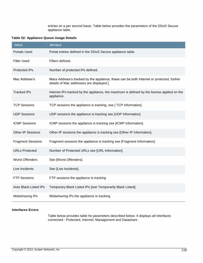
Copyright © 2013, Juniper Networks, Inc 118
entries on a per second basis. Table below provides the parameters of the DDoS Secure
appliance table.
Table 52: Appliance Queue Usage Details
FIELD DETAILS
Portals Used Portal entries defined in the DDoS Secure appliance table.
Filter Used Filters defined.
Protected IPs Number of protected IPs defined.
Mac Address’s Macs Address’s tracked by the appliance, these can be both Internet or protected, further
details of Mac addresses are displayed.].
Tracked IPs Internet IPs tracked by the appliance, the maximum is defined by the license applied on the
appliance.
TCP Sessions TCP sessions the appliance is tracking, see [ TCP Information].
UDP Sessions UDP sessions the appliance is tracking see [UDP Information].
ICMP Sessions ICMP sessions the appliance is tracking see [ICMP Information].
Other-IP Sessions Other-IP sessions the appliance is tracking see [Other IP Information].
Fragment Sessions Fragment sessions the appliance is tracking see [Fragment Information].
URLs Protected Number of Protected URLs see [URL Information].
Worst Offenders See [Worst Offenders].
Live Incidents See [Live Incidents].
FTP Sessions FTP sessions the appliance is tracking
Auto Black-Listed IPs Temporary Black Listed IPs [see Temporarily Black Listed].
Misbehaving IPs Misbehaving IPs the appliance is tracking
Interfaces Errors
Table below provides table he parameters described below. It displays all Interfaces
connected - Protected, Internet, Management and Datashare.

Copyright © 2013, Juniper Networks, Inc 119
Table 53: Interface Error Details
FIELD DETAILS
Interface Name The name of the interface that errors are potentially occurring on.
Drop-In (/s) Input packets dropped per second.
Drop-Out (/s) Output packets dropped per second.
Drop-Buf (/s) Packets dropped due to lack of buffers per second.
Framing (/s) The count and current/peak framing errors per second.
Collisions (/s) The count and current/peak packet collision errors per second.
Carrier (/s) The count and current/peak carrier errors per second.

Copyright © 2013, Juniper Networks, Inc 120
CHAPTER 5
DEFENSE INFORMATION
All anomalous behavior (attacks) is tracked on an Incident per Protected IP basis. When
an attack is active and running at a rate greater than or equal to the defined threshold,
reverse video on the right hand side of the display (Defense Status) changes from black to
red. During an attack with multiple components multiple attack indicators will be shown.
The attack indicator will go back from red to black when the event rate drops below the
threshold. Clicking on the hyperlink on an icon will cause all active Incidents for that type to
be displayed in the Center Pane. The last 31 days worth of incidents are available for
review, and can be accessed by using the Incident Logs entry under Junos DDoS
Configuration/Logs. You can disable an attack indication icon by disabling the creation of
incidents for the attack type on the Configure Logging page.
Operational Mode
Figure 94 displays the operational modes which are on the right hand side.
Figure 94: Operational Mode
Table below provides the operational modes available:
Table 54: Operational Modes Details
FIELD DETAILS
DEFENDING The DDoS Secure appliance has been configured to defend against any badly behaving
traffic.

Copyright © 2013, Juniper Networks, Inc 121
LOGGING The DDoS Secure appliance has been configured in Logging mode. In this configuration
the appliance monitors the traffic and flags any attacks detected. No packets are dropped.
All packets are passed through to the opposite interface. The dropped counters reflect
activity that would have been dropped if running in Defending mode. This can lead to
some subtle ambiguities in some of the statistics as dropped packets are allowed to
continue.
LOGGING TAP The DDoS Secure appliance has been configured in Logging-Tap mode. In this
configuration the appliance monitors traffic that is picked up by its Internet interface and
flags any attacks detected but does not pass the packets to the Protected Interface.
There should be no actual traffic on the Protected Interface. All “protected” IPs must be
defined, so that the appliance can differentiate which traffic is Internet or Protected IP.
BYPASS-SW The DDoS Secure appliance has been configured in BYPASS-SW mode. In this
configuration the appliance passes all the traffic directly through to its other interface. The
appliance does not monitor the traffic for attacks and therefore does not drop any packets.
BYPASS-HW The DDoS Secure appliance has been configured in BYPASS-HW mode. In this
configuration the fail-safe card has been forced into by-pass. The appliance does not
monitor the traffic for attacks and therefore does not drop any packets.
Failover States
Table 53 provides the failover states available:
Table 55: Failover State Details
STATE DETAILS
STANDALONE The DDoS Secure is running as a Standalone Entity
ACTIVE The DDoS Secure appliance is running as an Active partner of an Active/Standby
configuration and passing traffic
STANDBY The DDoS Secure appliance is running as a hot Standby partner of an Active/Standby
configuration and not passing traffic.
PROBE The DDoS Secure appliance is determining whether it should be a part of an
Active/Standby configuration. This will continue for 10 seconds, and then transition into
STANDALONE or STANDBY.
OUT-OF-SERVICE The DDoS Secure appliance is not capable of analyzing and hence passing traffic. The
fail-safe card may be operational though.

Copyright © 2013, Juniper Networks, Inc 122
Failover Information
Combined with one of the above Fail-Over states may be some IP addresses.
The IP addresses may be prefixed with one or more of the characters I, P or M. If any of
these characters are present, then this indicates a failed or failing communications link on
the Internet, Protected, or Management connections respectively between the two systems
that are trying to establish a partner relationship. The IP addresses have a trailing filed,
indicating the failover state of the remote partner.
State Synchronization Information
If DDoS Secure appliances are configured for sharing information ,this will be indicated by
the entry INFO SHARE. Following this there are entries of the IP address that are being
actively shared with. If the IP address is in Orange, then there has been a brief loss of
connection with the remote DDoS Secure.
Record / Replay State
Table below provides the record/replay state details.
Table 56: Record/Replay State Details
FIELD DETAILS
[Recording # #]
Traffic through the appliance is currently being recorded. The digit (1-9) indicates the recording
slot in use.
[Replaying # #] A previous recording of appliance traffic is being injected into the DDoS Secure appliance
processing engine. This traffic does not leave the appliance but does alter the defensive
responses of the engine. The digit (1-9) indicates the recording slot in use.
Transition States
Table below provides transition state details.
Table 57: Transition States Details
FIELD DETAILS
DDoS Secure appliance Initializing
The appliance Engine is starting up. In addition, the appropriate logic (xyz) that is being
initialized is also reported.
DDoS Secure appliance Going Offline
The appliance Engine is being shutdown. The Engine will then go offline. Depending on
whether powerdown, reboot or restart has been selected will depend on when the Engine
will next start to re-initialize or if the connection will be lost.
DDoS Secure appliance Offline
The appliance Engine is not currently running.

Copyright © 2013, Juniper Networks, Inc 123
DDoS Secure appliance Stall
This warning can be seen briefly sometimes when the system clock is adjusted. The
adjustment of the system clock can confuse the web interface briefly. If this warning
remains on for more than a few screen updates then the appliance Engine has hung, and is
no longer passing traffic. Should the warning remain on for more than a few screen
updates, take the appliance Engine Offline, and then back Online again by clicking,
SHUTDOWN DDoS SECURE followed by Shutdown DDoS Secure appliance Engine and
Restart. This is an unexpected condition.
Note: If several browser windows (on the same PC) are open on the same appliance, this
can also cause the appliance Stall light to come on – as a false positive - as the second
browser window may refresh its right hand pane at the same time as the first browser and
the webserver engine determines that there is not a time difference since the last refresh.
Appliance or Protected IP Information
Figure 95 displays the appliance or protected IP information.
Figure 95: Appliance or Protected IP information
The entry describes whether the Defense Status indicators are for the appliance, a Portal
or for a specific Protected IP. This will also apply to the data rate shown for the data on
many statistics pages.
Table below provides defense status indicators details.
Table 58: Transition States Details
FIELD DETAILS
Appliance Statistics Appliance statistics are being reported.

Copyright © 2013, Juniper Networks, Inc 124
Portal Portal Name Statistics
Specific portal statistics are being reported.
Protected IP aaa.bbb.ccc.ddd Statistics
Specific Protected IP statistics are being reported.
Some Protected IP Name Statistics
Specific Protected IP statistics are being reported. The protected IP was named in the
Configure portals screen.
In: 3.27M bit/s- Out: 6.17M bit/s: Inbound/Outbound bits rate
This reports the averaged Inbound and Outbound speed (data rate) for the appliance,
portal or for the Protected IP being monitored.
In: 341 pkt/s - Out: 541 pkt/s Inbound/Outbound packet rate
This reports the averaged Inbound and Outbound packet rate for the appliance, portal, or
for the Protected IP being monitored.
Defense Status
Figure 96 displays the defense status information.
Figure 96: Defense Information
If these lines go from black to red, then the appliance is defending against the type of
attack indicated. Clicking on the icon will cause all active Incidents pertaining to that type
of attack to be displayed. If this Incident type is not being displayed, then the icon hyperlink
will be removed.
Table below provides defense status details.

Copyright © 2013, Juniper Networks, Inc 125
Table 59: Defense Status Details
FIELD DETAILS
Bandwidth This indicates that appliance has detected that the bandwidth available to one or more
protected IPs or internet gateways is becoming critical and is in bandwidth defense mode.
Packets are being intelligently filtered to deny access from the most likely attackers. This
defense posture is applied per protected or internet gateway basis.
Packet Rate This indicates that appliance has detected high rates of small packets. DDoS Secure
appliance intelligently filters the stream of traffic dropping packets from the most likely
attackers.
Blocked Protocol Blocked Protocol includes TCP/UDP ports that are being dropped by the filter, as well as
ICMP types or other specific IP protocols, plus any blocked IP addresses. These invalid
ports / types / protocols are configured. The IP address blocking is automatic but needs to
be enabled.
Blocked State Blocked State includes when any packet that does not match the appliance internal state
machine for the specific protocol has been blocked. This includes protocols that are
stateless such as ICMP. With the random noise on the Internet, it is likely that this defense
light will be on for a large amount of the time. Broken TCP/IP stacks, and broken NAT
devices are a common cause of this random noise, as are the side effects of some DoS
attacks and port scanning tools.
IP Attack A form of IP attack is being directed at a protected IP. An example of this would be the Land
Attack.
TCP Attack A form of TCP attack is being directed at a protected IP. Examples of this would be the SYN
Attack or the Connection Flood.
UDP Attack A form of UDP attack is being directed at a protected IP.
ICMP Attack A form of ICMP attack is being directed at a protected IP.
Other IP Attack A form of attack based another IP protocol is being directed at a protected IP.
Fragment Attack In normal traffic, packets can be split (fragmented) into different packets, which are then
reassembled at the protected IP back into the original packet. Carefully crafted attack
packets can be used to create invalid packets when reassembled. This can have a
detrimental effect on the protected IP. appliance detects such attacks and drops the attack
packets before they reach the protected IP while allowing genuine packet fragments
through. Fragments dropped by a protected IP definition also turn on this light.
Bad Packets
(IP, ICMP, TCP, UDP
and O-IP)
The next five indicators on the right hand side of the appliance display indicate bad packets
are detected. These are packets that do not conform to the relevant RFCs and are dropped
at all times by DDoS Secure appliance

Copyright © 2013, Juniper Networks, Inc 126
Overloaded Protected IP
The appliance has detected that a Protected IP is no longer responding to connection
requests. This may be caused by a downed protected IP, a slow response to SYN requests,
or the protected IP is deliberately not responding to SYN requests on specific ports. To
reduce false alarms and to improve the auto-black-listing response to port scanners we
advice that you apply a suitable DDoS Secure appliance Permit filter. False alarms can also
be avoided by adjusting your host (or firewall) filtering policy to use deny or reject responses
to connection requests for a closed port, as opposed to drop responses.
Note: A drop response provides very few if any security benefits when defending against a
Port scan contrary to popular thinking.
Additional Status
Figure 97 displays additional status.
Figure 97: Additional Status
Additional information may be displayed about the defense status of the appliance. These
are defined in alphabetical order below (apart from SomeProtectedName), even though
they may be displayed in a different order.
Table below provides additional status details.
Table 60: Additional Status Details
FIELD DETAILS
Protected IP SomeProtectedName
This protected IP is being defended. Clicking on the URL link will cause the defense
state for that specific protected IP to be displayed. The protected IP name was specified
on the configuration screen.
BGP Misconfigured The DDoS Secure appliance has detected a BGP session, but the Server is excluded by
the DDoS Secure appliance portal network list.

Copyright © 2013, Juniper Networks, Inc 127
Black-Listed IP Table Full
The appliance has used up all the internal table space for tracking IP addresses that are
being temporarily black-listed. Any inactive black-listed IP address will be removed from
the list.
Config Transfer Failed
The DDoS Secure appliance was unable to transmit the configuration file changes to a
partner.
DataShare-I/F N/C The Data Share Interface (D-I/F) is not physically connected, and has an IP address
configured.
Disk Failure One of the disks has failed a SMART test and should be replaced as soon as possible.
Fan Failure The system BIOS is reporting that there has been a fan failure, or that the appliance is
running in hot environment. This needs to be repaired as soon as possible to prevent
hardware component failure.
Forced Inactive The appliance has detected that there is a Network Short Circuit situation prior to the
system being licensed. Consequently, no more traffic will be passed through until the
bypass situation is sorted out and the appliance restarted.
FRAGMENT Table Full The appliance has run out of internal table space for handling fragments. This table size
is deliberately restricted. The oldest (by use) entry has been dropped.
FTP Table Full The appliance has used up all the internal table space for tracking FTP connections.
Any entry not required will be flushed out to create space for the next FTP connection.
This should normally only happen when defending against a large-scale attack.
ICMP Table Full The appliance has run out of internal table space for ICMP sessions. This table size is
deliberately restricted. The oldest (by use) entry has been dropped. This should
normally only happen when defending against a large-scale attack.
Incident Table Full The appliance has run out of internal table space for active Incidents. The oldest (by
use) entry has been dropped.
Interface Speed Mismatch
On Fail-Safe systems, the interface speeds on the Fail-Safe card are defined, or
detected to be different, which will cause an issue if the card goes Fail-Safe.
Internet-I/F N/C The Internet Interface (I-I/F) is not physically connected. This occurs when the
appliance is running as STANDBY in a VMware environment.
Internet Sub-Link Down
One of the links on the Internet Interface (I-I/F) is not physically connected (WS-3G).
MAC Misconfigured A MAC address has been defined as type Internet, or type Protected, but the MAC
address has been detected on the opposite side of the DDoS Secure appliance. Correct
this situation.
MAC Table Full The appliance has run out of internal table space for MAC addresses. The oldest (by
use) entry has been dropped.

Copyright © 2013, Juniper Networks, Inc 128
Management-I/F N/C The Management Interface (M-I/F) is not physically connected.
Missing Partner A State Synchronization partner defined as required is not available. The DDoS Secure
appliance is running in a degraded state, where all DDoS activity will not be detected
and protected against.
Network Short Circuit The DDoS Secure appliance has detected the same source MAC address in use on
both the I-I/F and P-I/F interfaces. Bypass packets are not passed through the
appliance when in Defensive mode. This means that there is either an alternative data-
path around the Appliance, or a topology change has placed a previously determined
MAC address on the opposite side of the appliance. In the event of a topology change
the cached entry can be modified by configuring the MAC address as either an Internet
or Protected Gateway,or if not configured, the MAC will be allowed to change sides
automatically after 5 seconds.
New Configuration This is in response to the configuration being updated, potentially by a remote Wescreen.
Not Licensed The DDoS Secure appliance has not been authorized for use.
OTHER IP Protocols Table Full
The appliance has used up all the internal table space for IP Protocol sessions. Any
entry not required will be flushed out to create space for the next IP Protocol session.
This should normally only happen when defending against a large-scale attack.
Output Error – Internet DDoS Secure appliance is having trouble transmitting packets on the Internet Interface.
This could be because a downstream link is saturated, or a duplex speed mismatch.
Output Error - Management
DDoS Secure appliance is having trouble transmitting packets on the Management
Interface. This could be because a downstream link is saturated, or a duplex speed
mismatch.
Output Error – Protected
DDoS Secure appliance is having trouble transmitting packets on the Protected
Interface. This could be because a downstream link is saturated, or a duplex speed
mismatch.
Protected aaa.bbb.ccc.ddd
This protected IP is being defended. Clicking on the URL link will cause the defense
state for that specific protected IP to be displayed.
Protected-I/F N/C The Protected Interface (P-I/F) is not physically connected.
Protected IP Table Full The appliance has run out of internal table space for Protected IP addresses. This
usually indicates that your Internet and Protected cable connections are swapped. If
not, then your appliance is trying to protect too many protected IPs and the network
topology needs to be reviewed, or a feature upgrade purchased (if available).
Protected Sub-Link Down
One of the links on the Protected Interface (P-I/F) is not physically connected (WS-3G).
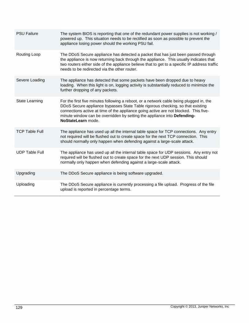
Copyright © 2013, Juniper Networks, Inc 129
PSU Failure The system BIOS is reporting that one of the redundant power supplies is not working /
powered up. This situation needs to be rectified as soon as possible to prevent the
appliance losing power should the working PSU fail.
Routing Loop The DDoS Secure appliance has detected a packet that has just been passed through
the appliance is now returning back through the appliance. This usually indicates that
two routers either side of the appliance believe that to get to a specific IP address traffic
needs to be redirected via the other router.
Severe Loading The appliance has detected that some packets have been dropped due to heavy
loading. When this light is on, logging activity is substantially reduced to minimize the
further dropping of any packets.
State Learning For the first five minutes following a reboot, or a network cable being plugged in, the
DDoS Secure appliance bypasses State Table rigorous checking, so that existing
connections active at time of the appliance going active are not blocked. This five-
minute window can be overridden by setting the appliance into Defending-
NoStateLearn mode.
TCP Table Full The appliance has used up all the internal table space for TCP connections. Any entry
not required will be flushed out to create space for the next TCP connection. This
should normally only happen when defending against a large-scale attack.
UDP Table Full The appliance has used up all the internal table space for UDP sessions. Any entry not
required will be flushed out to create space for the next UDP session. This should
normally only happen when defending against a large-scale attack.
Upgrading The DDoS Secure appliance is being software upgraded.
Uploading The DDoS Secure appliance is currently processing a file upload. Progress of the file
upload is reported in percentage terms.

Copyright © 2013, Juniper Networks, Inc 130
APPENDIX A
DDOS SECURE APPLIANCE TCP STATES
The following denotes the TCP states held by DDoS Secure appliance during operation.
These correspond approximately to the standard states held by a conventional TCP device,
but are subdivided due to the unique method of handling connections by DDoS Secure
appliance
Table below provides TCP status details.
Table 61: TCP Status Details
FIELD DETAILS
SYN Client has sent a SYN.
SPF Client has sent a SYN to a potentially internally filtered port.
SIF Client has sent a SYN to a potentially internally filtered IP address.
S-A Server has responded with SYN-ACK.
S-S Client and server SYN at the same time.
ACK Connection Established, but no data from Client or Server.
P-A Client sent data, Server not yet acknowledged any data.
GET Currently processing an HTTP GET / HEAD / POST request.
EST Connection established, data is flowing.
F1S Internet has sent a FIN.
F2S Protected ACK’d FIN.
F3S Internet sent FIN, Protected ACK’d FIN and has sent its own FIN.
F-F Internet and Protected sent FIN, but neither ACK’d FIN.
F1D Protected has sent a FIN.
F2D Internet has ACK’d FIN.
F3D Protected sent FIN, Internet ACK’d FIN and sent its own FIN.

Copyright © 2013, Juniper Networks, Inc 131
CLS Closed (All FINs ACK’d).
RST RESET (either end) to SYN.
R-C RESET (either end) to force session close.
UNK Session in unknown state.
GETs Count of connections processing a GET / HEAD request.

Copyright © 2013, Juniper Networks, Inc 132
APPENDIX B
ICMP TYPES
Table below provides ICMPv4 details.
Table 62: ICMPv4 Details
FIELD DETAILS
Echo Reply 0
Destination Unreachable 3
Source Quench 4
Redirect (change route) 5
Echo Request 8
Time Exceeded 11
Parameter Problem 12
Timestamp Request 13
Timestamp Reply 14
Information Request 15
Information Reply 16
Address Mask Request 17
Address Mask Reply 18
Table below provides ICMPv6 details.
Table 63: ICMPv6 Details
FIELD DETAILS
Destination Unreachable 1
Packet Too Big 2

Copyright © 2013, Juniper Networks, Inc 133
Time Exceeded 3
Parameter Problem 4
Echo Request 128
Echo Reply 129
Group Membership Query 130
Group Membership Reply 131
Group Membership Reduction 132
Router Solicitation 133
Router Advertisment 134
Neighbor Solicitation 135
Neighbor Advertisement 136
Redirect 137

Copyright © 2013, Juniper Networks, Inc 134
APPENDIX C
INCIDENT (ATTACK) TYPES
Table below provides type code details.
Table 64: Type Code Details
FIELD DETAILS
-2 Recorded in Auto-Black List.
-1 Packets not dropped, not recorded in Worst Offenders.
0 Not recorded in Worst Offenders.
1 Irritant attacks – used by Worst Offenders and Auto Black-List.
2 Resource consuming attacks – used by Worst Offenders and Auto Black-List.
Table below provides attack type code details.
Table 65: Attack Type Details
ATTACK TYPE TYPE DETAILS
Bad ICMP Packet – Malformed
1 ICMP header malformed (length, options and so on).
Bad IP Packet - Broken Header
1 IP header malformed – RFC non-compliant.
Bad IP Packet - Invalid
Option
1 IP packet has invalid option field or field length.
Bad IP Packet - Invalid
Source Address
0 IP packet has invalid source address.
Bad IP Packet - Reflected
Route
-1 IP packet is being reflected off a router – same packet is passed both
ways through the DDoS Secure appliance. Informational only.
Bad IP Packet - Size
Mismatch
1 IP packet has invalid field length.
Bad O-IP Packet - Length 1 IP packet too short to contain IP Protocol header.
Bad O-IP Packet - Protocol 1 Invalid IP protocol number.

Copyright © 2013, Juniper Networks, Inc 135
Bad TCP Packet - Fast
Repeat Ack
0 Identical packets containing ACKs are being repeated at a rate of greater
than 10 per second.
Bad TCP Packet - Flags 1 Invalid TCP flag combinations.
Bad TCP Packet -
Malformed
1 Format of TCP Header invalid.
Bad TCP Packet - Option 1 Invalid TCP option field.
Bad UDP Packet -
Malformed
1 UDP header malformed.
Bad UDP Packet - No data 1 UDP packet contains no data.
Bandwidth 2 Bandwidth rate exceeded for MAC address / portal / Filter.
Blocked Protocol – AS
Blocked
0 AS has been blocked.
Blocked Protocol – Black-
Listed
0 This IP address has been black-listed as it is part of a black-listed
network.
Blocked Protocol – Blocked
DNS
1 DNS query has been blocked.
Blocked Protocol – Blocked
URL
1 URL request has been blocked.
Blocked Protocol – Country
Blocked
0 Traffic to / from Country has been blocked.
Blocked Protocol - Icmp
Type
1 No filters match for this ICMP packet.
Blocked Protocol – Other
Proto
1 No filters match for this protocol type.
Blocked Protocol - Port 1 No Filter match for this destination port.
Blocked Protocol – Temp
Black-Listed
-2 This IP address has been temporarily black-listed.
Blocked Protocol –
Undefined Protected IP
0 Traffic to or from what is not defined as a protected IP address.
Fragment Attack - Bad
Length
2 Invalid fragment length in IP header.

Copyright © 2013, Juniper Networks, Inc 136
Fragment Attack - Header
Overlay
2 Fragment start overlays protocol header.
Fragment Attack - No
Fragments allowed
1 Fragmentation has been disabled in the Filter.
Fragment Attack - Ping of
Death
2 Assembled packet is longer than 65535 bytes.
Fragment Attack – Repeats 1 Same fragment is resent.
Fragment Attack – Small
Size
2 Initial TCP fragment is smaller than header.
Fragment Attack – Table
Full
1 Internal state table for fragments is full.
Fragment Attack – Timeout 2 Not all fragments seen.
ICMP Attack - Repeats 1 ICMP packets being repeated at a rate of more than 40 per second.
ICMP Attack - Table Full 1 Internal state table for ICMP is full.
IP Attack - Land 2 Source and destination IP addresses are equal.
Not Passed Thru – BPDU
Packet
0 Fail-Over mode does not allow through Spanning Tree packets.
Not Passed Thru – Cripple
State
0 Fail-Over is in Cripple state, no packets are being passed through.
Not Passed Thru –
Deactivated
0 DDoS Secure appliance has operationally closed down.
Not Passed Thru – Direction
Unknown
0 Logging-Tap only. MAC address not learnt yet.
Not Passed Thru –
Generated Response
0 ARP Packet generated by redirect server.
Not Passed Thru -
HeartBeat
0 Fail-Over heartbeat is never passed through a DDoS Secure appliance.
Not Passed Thru - Keep-
Alive Response
0 TCP response packet to internally generated Keep-Alive probe packet
has been dropped.

Copyright © 2013, Juniper Networks, Inc 137
Not Passed Thru - MAC
Misconfigured
0 A MAC address has been configured for one side of DDoS Secure
appliance, but this packet with this source MAC address has been seen
on the wrong side of the DDoS Secure appliance.
Not Passed Thru - MAC
Table Overflow
0 Internal table for MAC addresses is full. Oldest entry has been expired.
Not Passed Thru - Packet
From Us
0 Packet sent by someone pretending to be Internet or Protected
interface by using their MAC address.
Not Passed Thru - Packet
To Us
0 Packet sent to Internet or Protected interface MAC address.
Not Passed Thru - Pause
Frame
0 Ethernet Pause frame has been dropped.
Not Passed Thru - Probe
State
0 Fail-Over is in Probe state, so no traffic passing through yet.
Not Passed Thru – Runt
Packet
0 Undersized packet has been dropped.
Not Passed Thru - Same
Side
0 The source and destination MAC addresses both reside on the same
side of the DDoS Secure appliance.
Not Passed Thru - Short
Circuit Active
0 The same (source) MAC address has been seen on both sides of the
DDoS Secure appliance.
Not Passed Thru - Standby
State
0 Fail-Over is in Standby state – traffic flows through other DDoS Secure
appliance.
Not Passed Thru – State
Sync
0 State Synchronization packets are only processed.
Not Passed Thru – State
Sync Sent
0 State Synchronization packets are only processed.
Other-IP Attack - Table Full 1 Internal state table for Other IP protocols is full. Oldest entry has been
expired.
Overloaded IP - Backlog 1 The protected IP cannot keep up with new TCP connection requests.
Overloaded IP - Stall 1 The protected IP has stopped responding to anything.
Overloaded IP - Threads 2 The protected IP has stopped responding to new HTTP GET requests.
Packet Rate 2 Packet rate exceeded as defined in a filter or portal.

Copyright © 2013, Juniper Networks, Inc 138
TCP Attack – Client Abort 1 Client aborted connection after request.
TCP Attack - Connection
Flood
2 The protected IP has reached its concurrent connection configured limit.
TCP Attack - Connection
Rate Flood
2 The protected IP is receiving connection requests at a rate higher than
it is configured for.
TCP Attack - GET Flood 2 The protected IP has reached its concurrent GET/ HEAD configured
limit.
TCP Attack - GET
Incomplete
2 The HTTP GET request was never completed.
TCP Attack - GET Rate
Flood
2 The protected IP is receiving GET requests at a rate higher than it is
configured for.
TCP Attack - GET Timeout 1 The protected IP did not respond to a GET / HEAD request in a timely
manner.
TCP Attack - No Data Xfer 1 No data in either direction was transferred on the TCP connection. The
connection was just opened and then closed.
TCP Attack - No Server
Data Xfer
1 A web Server did not respond to a GET request. Usually seen when an
IP addresses is requested in the Host: header field, instead of a domain
name.
TCP Attack – Port Scan 2 A potential port scan was detected.
TCP Attack – RST 1 RST packet has invalid sequence number.
TCP Attack – Small Window 2 Client has closed TCP Window.
TCP Attack - Syn-Ack
Timeout
2 The client IP did not complete the TCP connection.
TCP Attack - Syn Flood 2 The protected IP is receiving SYN packets at a rate higher than it is
configured for or can handle.
TCP Attack - Table Full 1 Internal state table for TCP connections is full.
UDP Attack - Table Full 1 Internal state table for UDP information is full.
Unknown Session - Icmp
Diag Response
1 ICMP diagnostic response packet does not match a state table entry for
the respective IP protocol.
Unknown Session - Icmp
Response
1 ICMP response packet has no matching ICMP request in state table.

Copyright © 2013, Juniper Networks, Inc 139
Unknown Session - Invalid
State
1 TCP packet has a state table entry, but packet is out of state (sequence
numbers mismatch, or incorrect TCP flags).
Unknown Session - No
State
1 TCP packet has no state table entry and is not a SYN (start of
connection) packet.

Copyright © 2013, Juniper Networks, Inc 140

Copyright © 2013, Juniper Networks, Inc 141
APPENDIX D
LETTER COUNTRY CODES
Sorted by Code
---: --Unknown—
-bc: ---Broadcast--- Cannot be Blocked
-bl: ---Black List--- Always is Blocked
-bo: ---Bogon Address---
-ca: ---Country Allow ---
-ce: ---Class E---
-dc: ---Default Charm---
-lo: ---Loopback---
-mc: ---Multicast--- Cannot be Blocked
-mp: ---Mega Proxy--- Cannot be Blocked
-nb: ---No Auto Block---
-pl: ---Preferred List---
-pr: ---RFC1918 Address---
-u1: ---User Defined #1---
-u2: ---User Defined #2---
-u3: ---User Defined #3---
-u4: ---User Defined #4---
-u5: ---User Defined #5---
-u6: ---User Defined #6---
-u7: ---User Defined #7---
-u8: ---User Defined #8---
-u9: ---User Defined #9---
-wl: ---White List--- Cannot be Blocked
-wn: ---White No Log--- Cannot be blocked
A1 : Anonymous Proxy
A2 : Satellite Provider
ABW: Aruba
AFG: Afghanistan
AGO: Angola
AIA: Anguilla
ALA: Aland Islands
ALB: Albania
AND: Andorra
ANT: Netherlands Antilles
AP : Asia/Pacific Region
AQ : Antarctica
ARE: United Arab Emirates
ARG: Argentina
ARM: Armenia
ASM: American Samoa
ATG: Antigua and Barbuda
AUS: Australia
AUT: Austria
AZE: Azerbaijan
BDI: Burundi
BEL: Belgium
BEN: Benin
BFA: Burkina Faso
BGD: Bangladesh
BGR: Bulgaria
BHR: Bahrain
BHS: Bahamas
BIH: Bosnia and Herzegovina
BLR: Belarus
BLZ: Belize
BMU: Bermuda
BOL: Bolivia
BRA: Brazil
BRB: Barbados
BRN: Brunei Darussalam
BTN: Bhutan
BV : Bouvet Island
BWA: Botswana
CAF: Central African Republic
CAN: Canada
CC : Cocos (Keeling) Islands
CHE: Switzerland
CHL: Chile
CHN: China
CIV: Cote D'Ivoire
CMR: Cameroon
COD: Congo, The Democratic Republic of the
COG: Congo
COK: Cook Islands
COL: Colombia
COM: Comoros
CPV: Cape Verde
CRI: Costa Rica
CUB: Cuba
CX : Christmas Island
CYM: Cayman Islands
CYP: Cyprus
CZE: Czech Republic
DEU: Germany
DJI: Djibouti
DMA: Dominica
DNK: Denmark
DOM: Dominican Republic
DZA: Algeria
ECU: Ecuador
EGY: Egypt
ERI: Eritrea
ESH: Western Sahara
ESP: Spain
EST: Estonia
ETH: Ethiopia
EU : Europe
FIN: Finland
FJI: Fiji
FLK: Falkland Islands (Malvinas)
FRA: France
FRO: Faroe Islands
FSM: Micronesia, Federated States of
FX : France, Metropolitan
GAB: Gabon
GBR: United Kingdom
GEO: Georgia
GGY: Guernsey
GHA: Ghana
GIB: Gibraltar
GIN: Guinea
GLP: Guadeloupe
GMB: Gambia
GNB: Guinea-Bissau
GNQ: Equatorial Guinea
GRC: Greece
GRD: Grenada
GRL: Greenland
GS : South Georgia and the South Sandwich Islands
GTM: Guatemala
GUF: French Guiana
GUM: Guam
GUY: Guyana
HKG: Hong Kong
HM : Heard Island and McDonald Islands
HND: Honduras
HRV: Croatia
HTI: Haiti
HUN: Hungary

Copyright © 2013, Juniper Networks, Inc 142
IDN: Indonesia
IMN: Isle of Man
IND: India
IO : British Indian Ocean Territory
IRL: Ireland
IRN: Iran, Islamic Republic of
IRQ: Iraq
ISL: Iceland
ISR: Israel
ITA: Italy
JAM: Jamaica
JEY: Jersey
JOR: Jordan
JPN: Japan
KAZ: Kazakhstan
KEN: Kenya
KGZ: Kyrgyzstan
KHM: Cambodia
KIR: Kiribati
KNA: Saint Kitts and Nevis
KOR: Korea, Republic of
KWT: Kuwait
LAO: Lao People's Democratic Republic
LBN: Lebanon
LBR: Liberia
LBY: Libyan Arab Jamahiriya
LCA: Saint Lucia
LIE: Liechtenstein
LKA: Sri Lanka
LSO: Lesotho
LTU: Lithuania
LUX: Luxembourg
LVA: Latvia
MAC: Macau
MAR: Morocco
MCO: Monaco
MDA: Moldova, Republic of
MDG: Madagascar
MDV: Maldives
MEX: Mexico
MHL: Marshall Islands
MKD: Macedonia
MLI: Mali
MLT: Malta
MMR: Myanmar
MNE: Montenegro
MNG: Mongolia
MNP: Northern Mariana Islands
MOZ: Mozambique
MRT: Mauritania
MSR: Montserrat
MTQ: Martinique
MUS: Mauritius
MWI: Malawi
MYS: Malaysia
NAM: Namibia
NCL: New Caledonia
NER: Niger
NFK: Norfolk Island
NGA: Nigeria
NIC: Nicaragua
NIU: Niue
NLD: Netherlands
NOR: Norway
NPL: Nepal
NRU: Nauru
NZL: New Zealand
O1 : Other
OMN: Oman
PAK: Pakistan
PAN: Panama
PCN: Pitcairn Islands
PER: Peru
PHL: Philippines
PLW: Palau
PNG: Papua New Guinea
POL: Poland
PRI: Puerto Rico
PRK: Korea, Democratic People's Republic of
PRT: Portugal
PRY: Paraguay
PSE: Palestinian Territory
PYF: French Polynesia
QAT: Qatar
REU: Reunion
ROU: Romania
RUS: Russian Federation
RWA: Rwanda
SAU: Saudi Arabia
SDN: Sudan
SEN: Senegal
SGP: Singapore
SHN: Saint Helena
SJM: Svalbard and Jan Mayen
SLB: Solomon Islands
SLE: Sierra Leone
SLV: El Salvador
SMR: San Marino
SOM: Somalia
SPM: Saint Pierre and Miquelon
SRB: Serbia
STP: Sao Tome and Principe
SUR: Suriname
SVK: Slovakia
SVN: Slovenia
SWE: Sweden
SWZ: Swaziland
SYC: Seychelles
SYR: Syrian Arab Republic
TCA: Turks and Caicos Islands
TCD: Chad
TF : French Southern Territories
TGO: Togo
THA: Thailand
TJK: Tajikistan
TKL: Tokelau
TKM: Turkmenistan
TLS: Timor-Leste
TON: Tonga
TTO: Trinidad and Tobago
TUN: Tunisia
TUR: Turkey
TUV: Tuvalu
TWN: Taiwan
TZA: Tanzania, United Republic of
UGA: Uganda
UKR: Ukraine
UM : United States Minor Outlying Islands
URY: Uruguay
USA: United States
UZB: Uzbekistan
VAT: Holy See (Vatican City State)
VCT: Saint Vincent and the Grenadines
VEN: Venezuela
VGB: Virgin Islands, British
VIR: Virgin Islands, U.S.
VNM: Vietnam
VUT: Vanuatu
WLF: Wallis and Futuna
WSM: Samoa
YEM: Yemen
YT : Mayotte

Copyright © 2013, Juniper Networks, Inc 143
ZAF: South Africa
ZMB: Zambia
ZWE: Zimbabwee
Sorted by Country
-bl: ---Black List--- Always is Blocked
-bo: ---Bogon Address---
-bc: ---Broadcast--- Cannot be Blocked
-ca: ---Country Allow---
-ce: ---Class E---
-dc: ---Default Charm---
-lo: ---Loopback---
-mc: ---Multicast--- Cannot be Blocked
-mp: ---Mega Proxy--- Cannot be Blocked
-nb: ---No Auto Block---
-pt: ---Pen Test List---
-pl: ---Preferred List---
-pr: ---RFC1918 Address---
-u1: ---User Defined #1---
-u2: ---User Defined #2---
-u3: ---User Defined #3---
-u4: ---User Defined #4---
-u5: ---User Defined #5---
-u6: ---User Defined #6---
-u7: ---User Defined #7---
-u8: ---User Defined #8---
-u9: ---User Defined #9---
-wl: ---White List--- Cannot be Blocked
-wn: ---White No Log--- Cannot be Blocked
---: --Unknown--
AFG: Afghanistan
ALA: Aland Islands
ALB: Albania
DZA: Algeria
ASM: American Samoa
AND: Andorra
AGO: Angola
AIA: Anguilla
A1 : Anonymous Proxy
AQ : Antarctica
ATG: Antigua and Barbuda
ARG: Argentina
ARM: Armenia
ABW: Aruba
AP : Asia/Pacific Region
AUS: Australia
AUT: Austria
AZE: Azerbaijan
BHS: Bahamas
BHR: Bahrain
BGD: Bangladesh
BRB: Barbados
BLR: Belarus
BEL: Belgium
BLZ: Belize
BEN: Benin
BMU: Bermuda
BTN: Bhutan
BOL: Bolivia
BIH: Bosnia and Herzegovina
BWA: Botswana
BV : Bouvet Island
BRA: Brazil
IO : British Indian Ocean Territory
BRN: Brunei Darussalam
BGR: Bulgaria
BFA: Burkina Faso
BDI: Burundi
KHM: Cambodia
CMR: Cameroon
CAN: Canada
CPV: Cape Verde
CYM: Cayman Islands
CAF: Central African Republic
TCD: Chad
CHL: Chile
CHN: China
CX : Christmas Island
CC : Cocos (Keeling) Islands
COL: Colombia
COM: Comoros
COG: Congo
COD: Congo, The Democratic Republic of the
COK: Cook Islands
CRI: Costa Rica
CIV: Cote D'Ivoire
HRV: Croatia
CUB: Cuba
CYP: Cyprus
CZE: Czech Republic
DNK: Denmark
DJI: Djibouti
DMA: Dominica
DOM: Dominican Republic
ECU: Ecuador
EGY: Egypt
SLV: El Salvador
GNQ: Equatorial Guinea
ERI: Eritrea
EST: Estonia
ETH: Ethiopia
EU : Europe
FLK: Falkland Islands (Malvinas)
FRO: Faroe Islands
FJI: Fiji
FIN: Finland
FRA: France
FX : France, Metropolitan
GUF: French Guiana
PYF: French Polynesia
TF : French Southern Territories
GAB: Gabon
GMB: Gambia
GEO: Georgia
DEU: Germany
GHA: Ghana
GIB: Gibraltar
GRC: Greece
GRL: Greenland
GRD: Grenada
GLP: Guadeloupe
GUM: Guam
GTM: Guatemala
GGY: Guernsey
GIN: Guinea
GNB: Guinea-Bissau
GUY: Guyana
HTI: Haiti
HM : Heard Island and McDonald Islands
VAT: Holy See (Vatican City State)
HND: Honduras
HKG: Hong Kong
HUN: Hungary
ISL: Iceland
IND: India
IDN: Indonesia
IRN: Iran, Islamic Republic of
IRQ: Iraq
IRL: Ireland

Copyright © 2013, Juniper Networks, Inc 144
IMN: Isle of Man
ISR: Israel
ITA: Italy
JAM: Jamaica
JPN: Japan
JEY: Jersey
JOR: Jordan
KAZ: Kazakhstan
KEN: Kenya
KIR: Kiribati
PRK: Korea, Democratic People's Republic of
KOR: Korea, Republic of
KWT: Kuwait
KGZ: Kyrgyzstan
LAO: Lao People's Democratic Republic
LVA: Latvia
LBN: Lebanon
LSO: Lesotho
LBR: Liberia
LBY: Libyan Arab Jamahiriya
LIE: Liechtenstein
LTU: Lithuania
LUX: Luxembourg
MAC: Macau
MKD: Macedonia
MDG: Madagascar
MWI: Malawi
MYS: Malaysia
MDV: Maldives
MLI: Mali
MLT: Malta
MHL: Marshall Islands
MTQ: Martinique
MRT: Mauritania
MUS: Mauritius
YT : Mayotte
MEX: Mexico
FSM: Micronesia, Federated States of
MDA: Moldova, Republic of
MCO: Monaco
MNG: Mongolia
MNE: Montenegro
MSR: Montserrat
MAR: Morocco
MOZ: Mozambique
MMR: Myanmar
NAM: Namibia
NRU: Nauru
NPL: Nepal
NLD: Netherlands
ANT: Netherlands Antilles
NCL: New Caledonia
NZL: New Zealand
NIC: Nicaragua
NER: Niger
NGA: Nigeria
NIU: Niue
NFK: Norfolk Island
MNP: Northern Mariana Islands
NOR: Norway
OMN: Oman
O1 : Other
PAK: Pakistan
PLW: Palau
PSE: Palestinian Territory
PAN: Panama
PNG: Papua New Guinea
PRY: Paraguay
PER: Peru
PHL: Philippines
PCN: Pitcairn Islands
POL: Poland
PRT: Portugal
PRI: Puerto Rico
QAT: Qatar
REU: Reunion
ROU: Romania
RUS: Russian Federation
RWA: Rwanda
SHN: Saint Helena
KNA: Saint Kitts and Nevis
LCA: Saint Lucia
SPM: Saint Pierre and Miquelon
VCT: Saint Vincent and the Grenadines
WSM: Samoa
SMR: San Marino
STP: Sao Tome and Principe
A2 : Satellite Provider
SAU: Saudi Arabia
SEN: Senegal
SRB: Serbia
SYC: Seychelles
SLE: Sierra Leone
SGP: Singapore
SVK: Slovakia
SVN: Slovenia
SLB: Solomon Islands
SOM: Somalia
ZAF: South Africa
GS : South Georgia and the South Sandwich Islands
ESP: Spain
LKA: Sri Lanka
SDN: Sudan
SUR: Suriname
SJM: Svalbard and Jan Mayen
SWZ: Swaziland
SWE: Sweden
CHE: Switzerland
SYR: Syrian Arab Republic
TWN: Taiwan
TJK: Tajikistan
TZA: Tanzania, United Republic of
THA: Thailand
TLS: Timor-Leste
TGO: Togo
TKL: Tokelau
TON: Tonga
TTO: Trinidad and Tobago
TUN: Tunisia
TUR: Turkey
TKM: Turkmenistan
TCA: Turks and Caicos Islands
TUV: Tuvalu
UGA: Uganda
UKR: Ukraine
ARE: United Arab Emirates
GBR: United Kingdom
USA: United States
UM : United States Minor Outlying Islands
URY: Uruguay
UZB: Uzbekistan
VUT: Vanuatu
VEN: Venezuela
VNM: Vietnam
VGB: Virgin Islands, British
VIR: Virgin Islands, U.S.
WLF: Wallis and Futuna
ESH: Western Sahara
YEM: Yemen
ZMB: Zambia
ZWE: Zimbabwe

Copyright © 2013, Juniper Networks, Inc 145
APPENDIX E
PANEL AND CONNECTOR LOCATIONS
DDoS Secure1200-Failsafe Panels
Figure 98 and Figure 99 displays the front and rear panel of the DDoS Secure-1200-Failsafe.
Figure 98: Front Panel
Figure 99: Rear Panel
Table below provides the call out details.
Table 66: DDoS Secure 1200-FAILSAFE Call Out Details
CALL OUT DESCRIPTION
Front Panel
A Power ON/OFF Button
Rear Panel
A Not used
B Not Used
C I-I/F (Internet Interface)

Copyright © 2013, Juniper Networks, Inc 146
D P-I/F (Protected Interface)
E Serial Interface (Optional)
F Video (Optional)
G Keyboard + Mouse (Optional)
H M-I/F+ILO (1 Gbit Management PC Interface)
J D-I/F (Optional 1Gbit Data Share Interface)
K Power Supply
L Power Supply

Copyright © 2013, Juniper Networks, Inc 147
APPENDIX F
TROUBLESHOOTING
1. My browser gives an SSL connection error
If the DDoS Secure appliance SSL certificate changes for whatever reason, some PC Browsers choke on the previously installed certificate. If so, the old certificate will have to be removed by hand from the Browser Root Certificate cache. It is possible that exiting the browser and re-connecting fixes the situation.
2. How do I recover my lost Username and Password?
You are unable to recover the Username and Password. If Juniper staff able to access your appliance, they may be able to reset the password. It may be that you have to re-image the system.
3. What does Init Phase xxx mean?
When the appliance starts up, various large data sets have to be initialized. Each phase is the initialization of a different data set.
4. What does Exit Phase xxx mean?
When the appliance closes down, various large data sets have to be cleanly closed down. Each phase is the cleanup of a different data set.
5. Why do I get Protected IP Table Full turning to red?
The appliance is set up to protect a maximum number of protected IPs (see Configuration Overview information for the precise number). If this limit is exceeded, then “Protected IP Table Full” will turn to red. If your I-I/F and P-I/F connectors are reversed, the appliance is effectively protecting the Internet from your internal users. Confirm this using the PROTECTED INFO button. Correct any cabling errors. Review the location of the appliance in your network topology if the appliance has to protect more than the specified number of protected IPs. If cabling arrangements are logically reversed without physical disconnection, the DDoS Secure appliance engine must be restarted to ensure the correct automatic re-learning of the network topology. It is also possible to swap the Interfaces with CONFIGURE INTERFACES.

Copyright © 2013, Juniper Networks, Inc 148
APPENDIX G
GUI BRANDING
It is possible to customize both the GUI initial login landing page, as well as the format / style of pages that a portal user may be visiting.
Login Page
It is possible to customize this page by modifying the file customer.tmpl from the Manuals CD. The file has to be named customer.tmpl or host_uri-customer.tmpl, where host_uri is the name or IP that a user uses to access the DDoS Secure appliance.
customer.tmpl is preserved across software upgrades.
customer.tmpl can have reference to urls of external sites.
customer.tmpl can reference existing image files, or portal- specific images.
customer.tmpl must link to webviewcheck.wsp to enter the DDoS Secure appliance portal.
If the site is accessed with the URL https://some.host.com, then the search sequence is some.host.com-customer.tmpl, then customer.tmpl, and finally the original login page.
Images / CSS Files
Once a user has been logged in, they are then associated with a portal. Any .css file in the /css directory, or any images in the /images directory can be customized to modify the output.
Assume that a user is logged into portal CustomerX and is requesting css/center_pane.css. The search order would be css/portal-CustomerX-center_pane.css, then css/portal-center_pane.css and finally css/center_pane.css. The same is true for any images.
Updating Customized Files
To upload the files, on a Linux server, you need to collect all the customized files into a directory, and then running the following linux command to create an update package:-
echo "w.x.y" > webscreen- ; rm –f portal-clean ; tar cvf files.upg webscreen- *customer.tmpl patch-*.
where w.x.y is the current version of the DDoS Secure appliance (e.g. 5.13.1), and then upload files.upg as a DDoS Secure appliance patch.
Removing Customized Files
Run the following linux command to create an update package:-
echo "w.x.y" > webscreen- ; touch portal-clean ; tar cvf clean.upg webscreen- portal-clean
where w.x.y is the current version of the DDoS Secure appliance (e.g. 5.13.1), and then upload clean.upg as a DDoS Secure appliance patch.