DCS800 - Demo Unit Light (English - pdf - Data sheet) · DCS800 Demo Unit Light diagram, ratings...
4
DCS800 Demo Unit Light
-
Upload
phungduong -
Category
Documents
-
view
265 -
download
2
Transcript of DCS800 - Demo Unit Light (English - pdf - Data sheet) · DCS800 Demo Unit Light diagram, ratings...
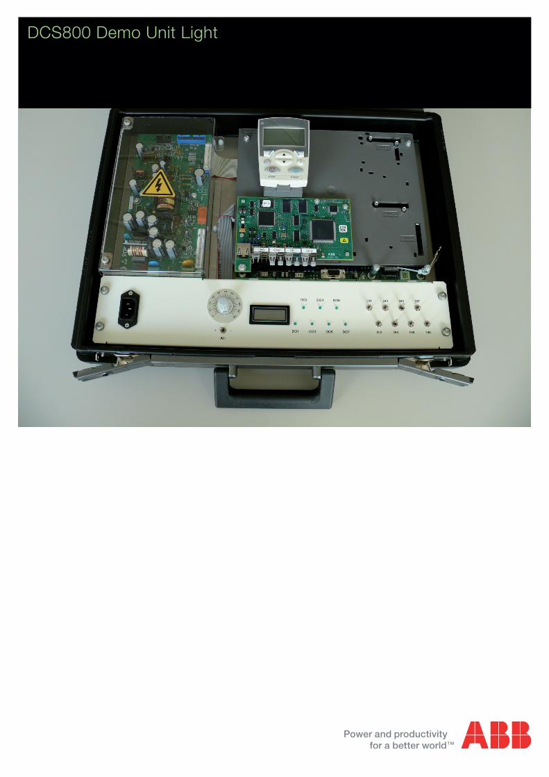
DCS800 Demo Unit Light
2 3ADW000410R0101 | DCS800 Demo Unit Light e a
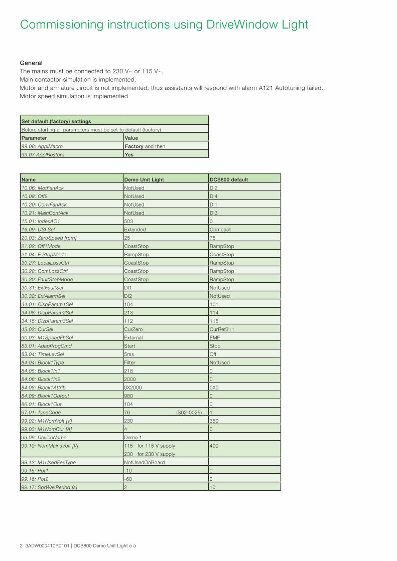
Commissioning instructions using DriveWindow Light
GeneralThe mains must be connected to 230 V~ or 115 V~. Main contactor simulation is implemented. Motor and armature circuit is not implemented, thus assistants will respond with alarm A121 Autotuning failed. Motor speed simulation is implemented
Name Demo Unit Light DCS800 default
10.06: MotFanAck NotUsed DI2
10.08: Off2 NotUsed DI4
10.20: ConvFanAck NotUsed DI1
10.21: MainContAck NotUsed DI3
15.01: IndexAO1 503 0
16.09: USI Sel Extended Compact
20.03: ZeroSpeed [rpm] 25 75
21.02: Off1Mode CoastStop RampStop
21.04: E StopMode RampStop CoastStop
30.27: LocalLossCtrl CoastStop RampStop
30.28: ComLossCtrl CoastStop RampStop
30.30: FaultStopMode CoastStop RampStop
30.31: ExtFaultSel DI1 NotUsed
30.32: ExtAlarmSel DI2 NotUsed
34.01: DispParam1Sel 104 101
34.08: DispParam2Sel 213 114
34.15: DispParam3Sel 112 116
43.02: CurSel CurZero CurRef311
50.03: M1SpeedFbSel External EMF
83.01: AdapProgCmd Start Stop
83.04: TimeLevSel 5ms Off
84.04: Block1Type Filter NotUsed
84.05: Block1In1 218 0
84.06: Block1In2 2000 0
84.08: Block1Attrib 0X2000 0X0
84.09: Block1Output 980 0
86.01: Block1Out 104 0
97.01: TypeCode 76 (S02-0025) 1
99.02: M1NomVolt [V] 230 350
99.03: M1NomCur [A] 4 0
99.09: DeviceName Demo 1
99.10: NomMainsVolt [V] 115 for 115 V supply
230 for 230 V supply
400
99.12: M1UsedFexType NotUsedOnBoard
99.15: Pot1 -10 0
99.16: Pot2 -60 0
99.17: SqrWavPeriod [s] 2 10
Set default (factory) settings
Before starting all parameters must be set to default (factory)
Parameter Value
99.08: ApplMacro Factory and then
99.07 ApplRestore Yes
3ADW000410R0101 | DCS800 Demo Unit Light e a 3
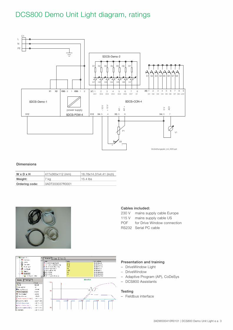
X99: 1 2
power supply
SDCS-POW-4
X7: 1 2 3 4 5 6 7 8 X6: 1 2 3 4 5 6 7 8 9DO1 DO2 DO3 DO4 DO5 DO6 DO7 0V DI1 DI2 DI3 DI4 DI5 DI6 DI7 DI8 +24V
X12 X4: 5 4 X3: 5 6
+ -
-10
V
+ 1
0 V
AI1
-
AI1
+
X4: 3 7
S1 S2 S3 S4 S5 S6 S7 S8
0 V
AO
1
R1 R2 R3 R4 R5 R6 R7
H1 H2 H3 H4 H5 H6 H7
P1V1
S9
L
N
PE
SDCS–CON-4
DC
S800 D
emo C
aseLite
single-phase
X1 X2
C1
X12
X96: 2 1
SDCS–Demo-2
SDCS–Demo-1
Verdrahtungsplan_incl_ADD.ppt
DCS800 Demo Unit Light diagram, ratings
Dimensions
W x D x H 477x365x112 (mm) 18.78x14.37x4.41 (inch)
Weight: 7 kg 15.4 lbs
Ordering code: 3ADT203037R0001
Cables included:230 V mains supply cable Europe 115 V mains supply cable US POF for Drive Window connection RS232 Serial PC cable
Presentation and training – DriveWindow Light – DriveWindow – Adaptive Program (AP), CoDeSys – DCS800 Assistants
Testing – Fieldbus interface

Contact us
© C
opyr
ight
201
1 A
BB
. All
right
s re
serv
ed.
3AD
W00
0410
R01
01 R
ev A
09
.201
1
Spe
cific
atio
ns s
ubje
ct to
cha
nge
with
out n
otic
e.ABB Automation ProductsWallstadter Straße 59 68526 Ladenburg, Germany Phone: +49 (0) 6203 71 0 Fax: +49 (0) 6203 71 7609 [email protected] www.abb.com/motors&drives