DCS World Su-25T Flight Manual En
69
[SU-25T] DCS Eagle Dynamics i DCS World Su-25T Flight Manual
description
Test
Transcript of DCS World Su-25T Flight Manual En

[SU-25T] DCS
Eagle Dynamics i
DCS World Su-25T
Flight Manual

DCS [Su-25T]
ii
DCS World Su-25T is the free to play PC game. The DCS World is base for installation of the paid modules by ED also.
General discussion forum in English: http://www.forums.eagle.ru

[Su-25T] DCS
Eagle Dynamics iii
Table of Contents
AIRCRAFT INTRODUCTION ............................................................................................ 1
SU-25Т FROGFOOT ............................................................................................................. 1
GAME AVIONICS MODE ................................................................................................ 3
NAVIGATION MODE ............................................................................................................. 5
AIR TO AIR MODE ............................................................................................................... 6
AIR TO GROUND MODE ........................................................................................................ 7
SU-25T COCKPIT INSTRUMENTS .................................................................................... 8
IAS – TAS Indicator ..................................................................................................................................... 9 Configuration Indicator .............................................................................................................................. 9 AOA Indicator and Accelerometer ........................................................................................................... 10 Attitude Director Indicator (ADI) .............................................................................................................. 10 Horizontal Situation Indicator (HSI) .......................................................................................................... 11 Vertical Velocity Indicator ........................................................................................................................ 11 Radar Altimeter ........................................................................................................................................ 12 Tachometer .............................................................................................................................................. 12 Fuel Quantity Indicator ............................................................................................................................ 13 Jet Engine Turbine Temperature Indicators ............................................................................................. 13 SPO-15 "Beryoza" Radar Warning Receiver ............................................................................................. 14 Weapon Status Panel ............................................................................................................................... 16 Weapon System Control Panel ................................................................................................................. 17 Autopilot (ACS) Panel ............................................................................................................................... 18
OPERATIONAL MODES OF THE SU-25Т HUD AND TV INDICATORS ............................................. 21 Basic HUD Symbology .............................................................................................................................. 21 Navigation Mode...................................................................................................................................... 22 Фи0 (Fi0) - Longitudinal Aiming Close Air Combat Mode ......................................................................... 23 "Air-to-Surface" Weapon Mode ............................................................................................................... 25 Precision Strike......................................................................................................................................... 28 Fixed Reticle Sight .................................................................................................................................... 34
RADIO COMMUNICATIONS AND MESSAGES ............................................................... 36
RADIO COMMANDS ........................................................................................................... 36
RADIO MESSAGES .............................................................................................................. 40
VOICE MESSAGES AND WARNINGS ....................................................................................... 42
SU-25T ADVANCED FLIGHT DYNAMICS MODEL ........................................................... 44
Cold Engine Start Procedure From the Parking Ramp .............................................................................. 46
DCS [Su-25T]
iv
In Air Automatic engine start .................................................................................................................... 46
SPECIAL CONSIDERATIONS FOR FLYING THE SU-25T ................................................................. 47 Taxi ........................................................................................................................................................... 47 Take-off ..................................................................................................................................................... 47 Crosswind Take-off ................................................................................................................................... 47 Landing ..................................................................................................................................................... 47 Crosswind Landing .................................................................................................................................... 48 Common Landing Errors ........................................................................................................................... 48 Stalls and Spins ......................................................................................................................................... 48
WEAPONS DELIVERY ................................................................................................... 50
SU-25T ........................................................................................................................... 50 Air-to-Air Weapons ................................................................................................................................... 50 Air-to-Ground Weapons ........................................................................................................................... 51
SUPPLEMENTS ............................................................................................................ 61
ACRONIM LIST .................................................................................................................. 61
[Su-25T] DCS
Eagle Dynamics 1
AIRCRAFT INTRODUCTION
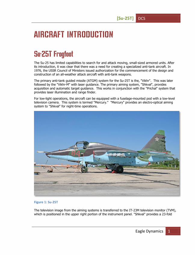
Su-25Т Frogfoot The Su-25 has limited capabilities to search for and attack moving, small-sized armored units. After its introduction, it was clear that there was a need for creating a specialized anti-tank aircraft. In 1976, the USSR Council of Ministers issued authorization for the commencement of the design and construction of an all-weather attack aircraft with anti-tank weapons.
The primary anti-tank guided missile (ATGM) system for the Su-25T is the, "Vikhr". This was later followed by the "Vikhr-M" with laser guidance. The primary aiming system, "Shkval", provides acquisition and automatic target guidance. This works in conjunction with the "Prichal" system that provides laser illumination and range finder.
For low-light operations, the aircraft can be equipped with a fuselage-mounted pod with a low-level television camera. This system is termed "Mercury." "Mercury" provides an electro-optical aiming system to "Shkval" for night-time operations.
Figure 1: Su-25T
The television image from the aiming systems is transferred to the IT-23M television monitor (TVM), which is positioned in the upper right portion of the instrument panel. "Shkval" provides a 23-fold
DCS [Su-25T]
2
target magnification, "Mercury" – provides a five-fold level of magnification. This helps identify distant targets: a house – 15 km, a tank – 8-10 km, a helicopter like an "Apache" – 6 km.
The integrated Electronic Warfare (EW) system provides detection and direction finding of air, ground, and naval radar emitters, with an accuracy of +/- 30 degrees in azimuth. The EW system can detect and classify radars emitting in the 1.2-18 GHz bands. Adjustable, Electronic Attack (EA) jamming can be used to reduce the effectiveness of weapon control radars operating in continuous wave and pulse modes. EA pods can be fixed to under-wing suspension hard points. For protection against infrared-guided missiles, expendable flares are used. The Su-25T is equipped 192 flare cartridges. Also for protection against infrared-guided missiles, the electro-optical jamming system "Sukhogruz" is installed in the tail section of the aircraft. This powerful, cesium lamp, with an energy consumption of 6 kW, creates an amplitude-modulated jamming signal that prevents infrared-guided missiles from guiding.
To engage air defense radars, the Su-25T can be equipped with the target designation pod "Viyuga" or "Phantasmagoria" target designation pods. This allows the Su-25T to designate targets for anti-radar missiles such as the Kh-58 and Kh-25MPU.
Although the Su-25T is much improved from the standard Su-25 in regards to its weapon delivery capabilities, its flight performance has taken a step back. The added weight in particular has given the Su-25T poor performance and handling. The Su-25T is a powerful weapon platform but it takes a skilled pilot to fly it well.
When flying the Su-25T in Lock On, it is suggested that you set your input controls to linear axis. This will provide the most realistic control of the aircraft.

[Su-25T] DCS
Eagle Dynamics 3
GAME AVIONICS MODE The Game Avionics Mode provides "arcade-style" avionics that make the game more accessible and familiar to the casual gamer.
This mode can be selected from the Gameplay Options tabe or by setting the Game Presets to Game. Please see Options chapter of GUI manual for more details.
Figure 2: Game Avionics Mode Radar Dysplay
The display, located in the top right corner of the screen is a top down view with your aircraft (green circle) located at the bottom center of the display. Symbols located above your symbol are located in front of you, symbols to the right and left are located to the side of you.
The below images illustrate the various features of the Game Avionics Mode. Note that you will see different symbols depending what mode the aircraft is in: Navigation, Air to Air or Air to Ground.
Game Avionics Mode Radar Dysplay

DCS [Su-25T]
4 GAME AVIONICS MODE
However, each mode will have the following data in common:
Mode. Indicated outside of the top left corner of the display. This can show NAV (navigation), A2A (air to air) or A2G (air to ground).
Mode keys:
o Navigation: [1]
o Air to Air: [2], [4] or [6]
o Air to Ground: [7]
Radar Range. Outside the top right of the display is the current range setting of the easy radar.
Radar range keys:
o Zoom in: [=]
o Zoom out: [-]
True Air Speed (TAS). Outside the lower left of the display is the true airspeed of your aircraft.
Radar Altitude. Outside the lower right of the display is the radar altimeter that indicates your altitude above the ground or water.
Current Heading. Inside the display at the center top is your current aircraft magnetic heading.
[Su-25T] DCS
Eagle Dynamics 5
Navigation Mode
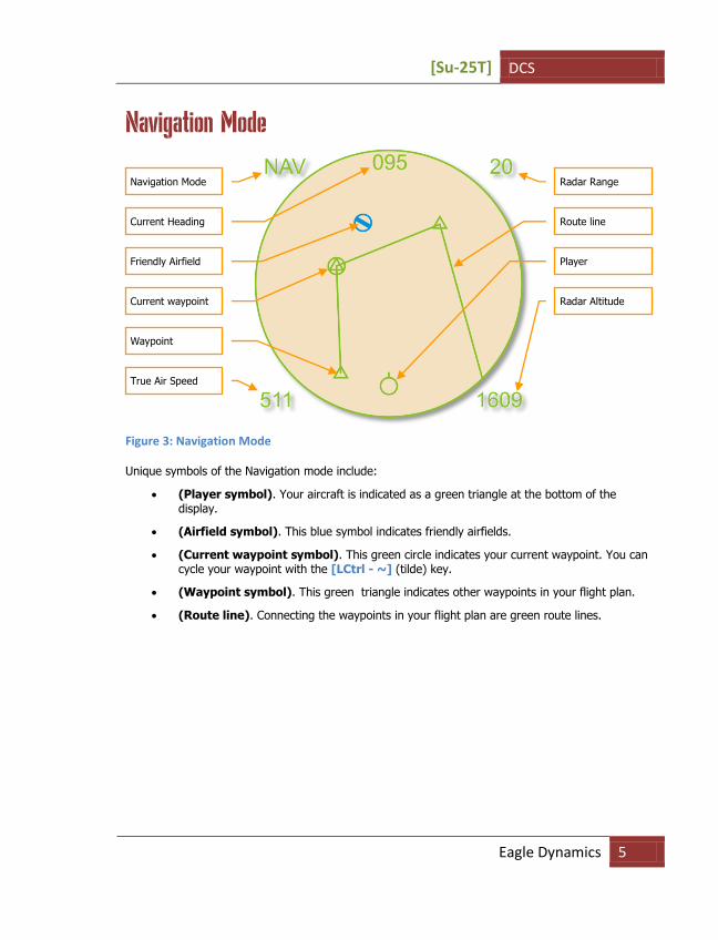
Figure 3: Navigation Mode
Unique symbols of the Navigation mode include: (Player symbol). Your aircraft is indicated as a green triangle at the bottom of the
display.
(Airfield symbol). This blue symbol indicates friendly airfields.
(Current waypoint symbol). This green circle indicates your current waypoint. You can cycle your waypoint with the [LCtrl - ~] (tilde) key.
(Waypoint symbol). This green triangle indicates other waypoints in your flight plan.
(Route line). Connecting the waypoints in your flight plan are green route lines.
Navigation Mode
Current Heading
Friendly Airfield
Current waypoint
Waypoint
True Air Speed
Radar Range
Route line
Player
Radar Altitude

DCS [Su-25T]
6 GAME AVIONICS MODE
Air to Air Mode
Figure 4: Air to Air Mode
Unique symbols of the Air to Air mode include:
(Player symbol). Your aircraft is indicated as a green circle at the bottom of the display.
(Friendly aircraft). All friendly aircraft are indicated as blue circles with lines coming from them that indicate flight direction.
(Enemy aircraft). All friendly aircraft are indicated as red circles with lines coming from them that indicate flight direction.
(Friendly missile). A friendly missile is indicated as a blue dot.
(Enemy missile). A friendly missile is indicated as a red dot.
Useful key commands when in Air to Air mode include:
Auto Lock Center Aircraft: [RAlt - F6]
Auto Lock Nearest Aircraft: [RAlt - F5]
Auto Lock On Next Aircraft: [RAlt - F7]
Auto Lock Previous Aircraft: [RAlt - F8]
Air to Air Mode
Current Heading
Friendly missile
Friendly aircraft
True Air Speed
Radar Range
Enemy aircraft
Player
Radar Altitude
Enemy missile
[Su-25T] DCS
Eagle Dynamics 7
Air to Ground Mode
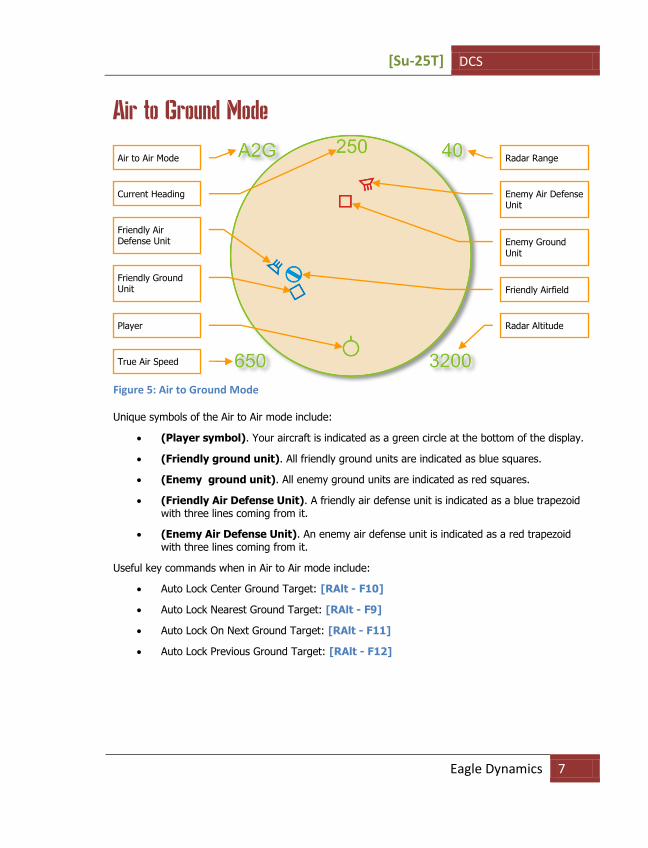
Figure 5: Air to Ground Mode
Unique symbols of the Air to Air mode include:
(Player symbol). Your aircraft is indicated as a green circle at the bottom of the display.
(Friendly ground unit). All friendly ground units are indicated as blue squares.
(Enemy ground unit). All enemy ground units are indicated as red squares.
(Friendly Air Defense Unit). A friendly air defense unit is indicated as a blue trapezoid with three lines coming from it.
(Enemy Air Defense Unit). An enemy air defense unit is indicated as a red trapezoid with three lines coming from it.
Useful key commands when in Air to Air mode include:
Auto Lock Center Ground Target: [RAlt - F10]
Auto Lock Nearest Ground Target: [RAlt - F9]
Auto Lock On Next Ground Target: [RAlt - F11]
Auto Lock Previous Ground Target: [RAlt - F12]
Air to Air Mode
Current Heading
Friendly Air Defense Unit
Friendly Ground Unit
True Air Speed
Radar Range
Enemy Air Defense Unit
Player Radar Altitude
Enemy Ground Unit
Friendly Airfield

DCS [Su-25T]
8 SU-25T COCKPIT INSTRUMENTS
SU-25T COCKPIT INSTRUMENTS
Figure 6: The Su-25Т Instrument Panel
1. Landing gear control lever
2. Autopilot control panel (ACS)
3. Angle of Attack (AOA) indicator and Accelerometer ("G meter")
4. Airspeed indicator (IAS)
5. Attitude director indicator (ADI)
6. Vertical velocity indicator (VVI)
7. Tachometer (revolutions per minute or RPM)
8. Fuel quantity indicator
9. "EKRAN" built-in test system display
10. SPO-15 "Beryoza" radar warning receiver (RWR) panel
1
13
4 5 6 7 8 9
23
12 2
22 21 20 19 18 17 16 14
11 10
15
3

[Su-25T] DCS
Eagle Dynamics 9
11. IТ-23М cathode ray tube (CRT) television (TV) display
12. Aircraft clock
13. "Sukhogruz" infrared (IR) jammer indicator lamp
14. Weapon system control panel (WCS)
15. Flaps, slats, airbrake and landing gear configuration indicator
16. Radar altimeter
17. Barometric pressure altimeter
18. Horizontal situation indicator (HSI)
19. Neutral (takeoff) trim in pitch, roll and yaw indicator lamp
20. Weapon status panel
21. Engine temperature
22. Hydraulic pressure meters
23. Warning lamps
IAS – TAS Indicator The IAS - TAS gauge indicates the aircraft’s True Air Speed (TAS) in the interior of the gauge and Indicated Air Speed (IAS) in the outer portion of the gauge. The speed scale ranges from 0 to 1,100 kph.
Figure 7: Su-25 IAS- TAS Indicator
Configuration Indicator The configuration indicator for mechanical devices shows the position of the landing gear, flaps, and airbrakes. If the landing gear is not successfully extended or retracted, a red lamp lights in the center of the indicator.
TAS
IAS
DCS [Su-25T]
10 SU-25T COCKPIT INSTRUMENTS
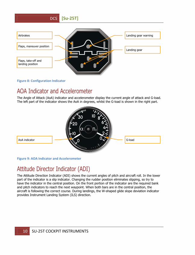
Figure 8: Configuration Indicator
AOA Indicator and Accelerometer The Angle of Attack (AoA) indicator and accelerometer display the current angle of attack and G-load. The left part of the indicator shows the AoA in degrees, whilst the G-load is shown in the right part.
Figure 9: AOA Indicator and Accelerometer
Attitude Director Indicator (ADI) The Attitude Direction Indicator (ADI) shows the current angles of pitch and aircraft roll. In the lower part of the indicator is a slip indicator. Changing the rudder position eliminates slipping, so try to have the indicator in the central position. On the front portion of the indicator are the required bank and pitch indicators to reach the next waypoint. When both bars are in the central position, the aircraft is following the correct course. During landings, the W-shaped glide slope deviation indicator provides Instrument Landing System (ILS) direction.
Airbrakes
Flaps, maneuver position
Flaps, take-off and landing position
Landing gear warning
Landing gear
AoA indicator
G-load
[Su-25T] DCS
Eagle Dynamics 11
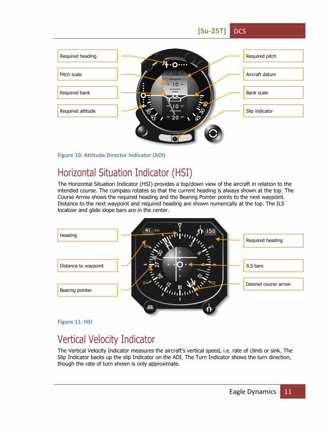
Figure 10: Attitude Director Indicator (ADI)
Horizontal Situation Indicator (HSI) The Horizontal Situation Indicator (HSI) provides a top/down view of the aircraft in relation to the intended course. The compass rotates so that the current heading is always shown at the top. The Course Arrow shows the required heading and the Bearing Pointer points to the next waypoint. Distance to the next waypoint and required heading are shown numerically at the top. The ILS localizer and glide slope bars are in the center.
Figure 11: HSI
Vertical Velocity Indicator The Vertical Velocity Indicator measures the aircraft’s vertical speed, i.e. rate of climb or sink. The Slip Indicator backs up the slip Indicator on the ADI. The Turn Indicator shows the turn direction, though the rate of turn shown is only approximate.
Required heading
Pitch scale
Required bank
Required altitude
Required pitch
Aircraft datum
Bank scale
Slip indicator
Heading
Distance to waypoint
Bearing pointer
Required heading
ILS bars
Desired course arrow
DCS [Su-25T]
12 SU-25T COCKPIT INSTRUMENTS
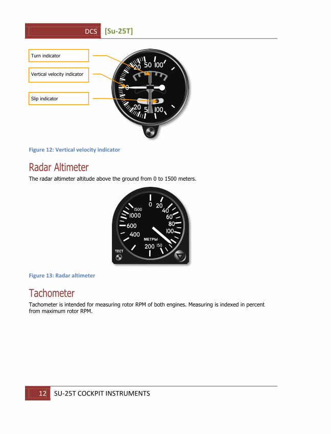
Figure 12: Vertical velocity indicator
Radar Altimeter The radar altimeter altitude above the ground from 0 to 1500 meters.
Figure 13: Radar altimeter
Tachometer Tachometer is intended for measuring rotor RPM of both engines. Measuring is indexed in percent from maximum rotor RPM.
Turn indicator
Vertical velocity indicator
Slip indicator

[Su-25T] DCS
Eagle Dynamics 13
Figure 14: Tachometer
Fuel Quantity Indicator Fuel quantity (P) shows the fuel remaining in all tanks. Fuel quantity (T) shows the fuel remaining in the feeder tank.
If external fuel tanks are carried, a warning light indicates that they are nearing empty.
Figure 15: Fuel Quantity Indicator
Jet Engine Turbine Temperature Indicators The two inter-stage turbine temperature indicators show the temperature of the exhaust gas from the left and right engine turbines.
All tanks fuel quantity
Tank warning
Bingo
Feeder tank fuel quantity

DCS [Su-25T]
14 SU-25T COCKPIT INSTRUMENTS
Figure 16: Engine Temperature Indicator
SPO-15 "Beryoza" Radar Warning Receiver The RWR display indicates any threat radars illuminating ("painting") the aircraft. Information is presented as symbols representing the type and direction to the threat. Six illuminated symbols at the bottom of the display notify the pilot of the threat radar type. The system indicates both enemy and friendly radars.
The system provides detection of radar signals at the following angles: Azimuth - +/- 180, and Elevation Range - +/- 30.
The maximum number of threats on screen: Unlimited.
The threat history display duration time: 8 seconds.
Function modes: All (acquisition) or Lock (the "ОБЗОР/ОТКЛ" switch).
Threats types:
П – airborne radar
З - long-range radar
X - medium-range radar
H - short-range radar
F - early warning radar
C - AWACS
"Relative elevation" lights, "power of emission" gauge lights and "Lock/Launch" lights are only in regards to the primary threat.
If the time between radar spikes of threat radar is eight or more seconds, the azimuth lights will not blink.
In the case of an acquisition-type spike, the low frequency audio tone will sound.

[Su-25T] DCS
Eagle Dynamics 15
If a radar is in lock mode, the "Lock/Launch" indicator will light up, along with a steady, high frequency audio tone.
If a radar-guided missile launch is detected, the "Lock/Launch" light will flash, along with a high pitched audio tone.
An ARH missile can be detected by the system after a missile establishes a lock using its own radar seeker. In this case, the missile will become the primary threat. The cue to recognize an ARH missile is the rapid increase in signal strength ("power of emission" lamps).
Figure 17: "Beryoza" SPO-15LM indicator
The ability to correctly interpret the information indicated on RWS panel is vital in combat.
As an example, let’s take a look at the situation shown in picture above.
As is seen in the picture, two threats are indicated on RWS panel:
1. The primary threat at 50 degrees left (10 o’clock) is indicated in the form of a large yellow lamp. The lamp above "П" symbol, which means "interceptor", is lit. This type of threat includes all fighters. The circular scale of signal power ("light strip") consists of yellow segments that show the relative emission power of the primary threat’s radar. The large red circle under the aircraft symbol indicates that your aircraft has been locked by the primary threat radar. The lit, yellow hemispheres marked as "В" and "Н" in the center of the aircraft silhouette, indicates the threat’s relative altitude to yours. In this situation, the primary threat is at the same altitude as your own, within 15 degrees in elevation. Consequently, the display can be interpreted in the following way: your primary threat is a
Direction to the primary
threat
Own aircraft mark on the
"light strip"
Primary threat type
Secondary threat type
Power light
"Light strip" - Relative
emmission power the
primary threat, estimate
range to threat
Relative elevation of the
primary threat
Red flashing lamp -
launch indication
Direction to the
secondary threat

DCS [Su-25T]
16 SU-25T COCKPIT INSTRUMENTS
fighter approaching from 10 o’clock; it is near co-altitude with you; and judging by the signal strength and lock light, it is ready to launch a missile.
2. The secondary threat is positioned at 10-30 degrees azimuth (1-2 o’clock right), and this is indicated by the two green lamps. The green "Х" symbol in the threat types line indicates that your being targeted by a medium-range radar. There is no additional data on secondary threats.
In a complex threat environment, it is often difficult to define the threat type and direction. In this case it is recommended to use the RWS mode filter [RShift-R] that removes all emitters operating in acquisition mode.
The RWR can produce multiple audio alerts. You can adjust their volume by pressing [RAlt-,] – [RAlt-.] keys.
Weapon Status Panel Weapon status panel is located beneath the throttle handle in the left side cockpit instrument panel. The type, quantity and readiness of the currently selected weapon and the remaining gun ammunition are indicated.
Figure 18: Weapons status panel
The yellow lamps in the upper row indicate weapon availability and presence on hardpoint stations. When ordnance is launched or released, the corresponding yellow lamp goes dark.
The green lamps in the lower row indicate currently selected weapons that are ready for launch or release.
The currently selected weapon type is indicated in the upper right of the panel: Б for bombs, УР for missiles, НРС for rockets, ВПУ for the built-in 30 mm cannon.
The remaining cannon rounds is indicated in the lower right of the panel: К for full, 1/2 for one-half, 1/4 for one-quarter.
Weapon availability
Weapons ready for use
Weapon type indicator
Gun rounds remaining (in
quarters)
[Su-25T] DCS
Eagle Dynamics 17
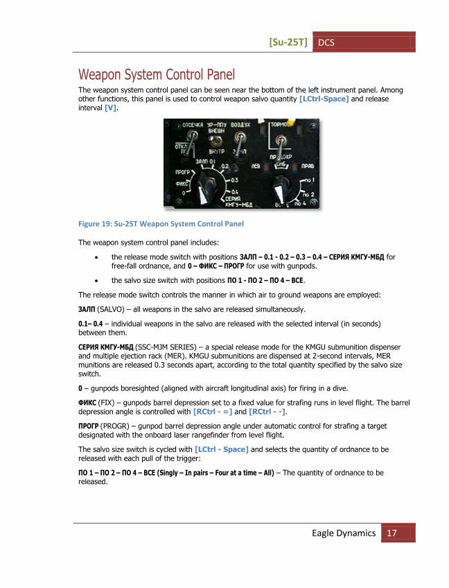
Weapon System Control Panel The weapon system control panel can be seen near the bottom of the left instrument panel. Among other functions, this panel is used to control weapon salvo quantity [LCtrl-Space] and release interval [V].
Figure 19: Su-25T Weapon System Control Panel
The weapon system control panel includes:
the release mode switch with positions ЗАЛП – 0.1 - 0.2 – 0.3 – 0.4 – СЕРИЯ КМГУ-МБД for free-fall ordnance, and 0 – ФИКС – ПРОГР for use with gunpods.
the salvo size switch with positions ПО 1 - ПО 2 – ПО 4 – ВСЕ.
The release mode switch controls the manner in which air to ground weapons are employed:
ЗАЛП (SALVO) – all weapons in the salvo are released simultaneously.
0.1– 0.4 – individual weapons in the salvo are released with the selected interval (in seconds) between them.
СЕРИЯ КМГУ-МБД (SSC-MJM SERIES) – a special release mode for the KMGU submunition dispenser and multiple ejection rack (MER). KMGU submunitions are dispensed at 2-second intervals, MER munitions are released 0.3 seconds apart, according to the total quantity specified by the salvo size switch.
0 – gunpods boresighted (aligned with aircraft longitudinal axis) for firing in a dive.
ФИКС (FIX) – gunpods barrel depression set to a fixed value for strafing runs in level flight. The barrel depression angle is controlled with [RCtrl - =] and [RCtrl - -].
ПРОГР (PROGR) – gunpod barrel depression angle under automatic control for strafing a target designated with the onboard laser rangefinder from level flight.
The salvo size switch is cycled with [LCtrl - Space] and selects the quantity of ordnance to be released with each pull of the trigger:
ПО 1 – ПО 2 – ПО 4 – ВСЕ (Singly – In pairs – Four at a time – All) – The quantity of ordnance to be released.

DCS [Su-25T]
18 SU-25T COCKPIT INSTRUMENTS
Note that even the ПО 1 setting will still release ordnance hung from the outermost weapon stations in symmetric pairs, to avoid excessively unbalancing the aircraft. Only the four innermost wing stations provide individual weapon release with this setting.
MERs always release all attached weapons together. It is not possible to command individual bomb release from the Su-25T’s MERs.
When using onboard or podded guns, the salvo size switch positions assume a different meaning:
ПО 1 (FOR 1) – Internal cannon only.
ПО 2 (FOR 2) – Firing with a single pair of gunpods.
ПО 4 (FOR 4) – Firing with all gunpods.
With gunpods selected, strafing in a line can be accomplished from level flight in the ФИКС mode, controlling barrel deflection with [RCtrl-=] and [RCtrl--].
The ПРОГР mode is used to concentrate gunpod fire on a point target from horizontal flight. For this it is necessary to depress the barrels to the desired angle with [RCtrl-=] and [RCtrl--], switch on the laser range-finder - [RShift-O], maneuver the aircraft to put the pipper over the target and pull and hold the trigger. The gun barrels will automatically start firing at the right time, then deflect automatically in vertical plane to stay on target.
Autopilot (ACS) Panel The ACS-8 automatic control system (ACS or "autopilot") panel is located in the left instrument panel. It indicates the ACS operational mode and includes six illuminated pushbuttons.
The available ACS operating modes include:
Route-following and Landing;
Combat steering;
Attitude hold mode (retains current pitch and bank);
Barometric altitude hold;
Barometric altitude and bank angle hold;
Emergency leveling mode;
Radar altitude hold with automatic terrain avoidance;
Momentary override (programming) mode.
Figure 20: ACS Panel
[Su-25T] DCS
Eagle Dynamics 19
The attitude and/or altitude hold modes attempt to retain the aircraft and/or altitude as it was the moment the mode was engaged.
In all modes except for "Emergency leveling", "Route-following" and "Landing," the ACS is limited to ±60 degrees in bank and ±35 degrees in pitch. When any of these limits is reached, the ACS disengages and the aircraft reverts to manual control. ACS modes cannot be engaged beyond these limits.
The ACS is further limited to 15 degrees angle of attack (AOA) and 0-3 G, as measured by the aircraft instruments. It is not recommended to engage the autopilot at AOAs exceeding 12 degrees. If AOA exceeds 12 degrees while the autopilot is active, the pilot should immediately advance the engine throttles to increase airspeed and thrust.
The "momentary override" mode is engaged by pressing and holding [LAlt-~] in any autopilot mode (corresponding to the "SAU" trigger on the control stick of the real Su-25T). This mode allows temporary manual control of the aircraft, usually to adjust the desired attitude and/or altitude. This override mode has two peculiarities in the "Combat steering" ACS mode (see the description of the "Combat steering" mode further below).
Pressing [LAlt-9] will disable any engaged ACS modes (corresponding to the "OTKL. SAU" trigger on the control stick of the real Su-25T).
Route-following mode - АУ-МАРШР. This mode is selected by pressing the [А] or [LAlt-6] key with the aircraft avionics in the "ENROUTE" or "RETURN" navigation operational mode. The autopilot follows the assigned flight path.
Landing mode - АУ-ПОСАД. This mode is selected by pressing the [А] or [LAlt-6] key with the aircraft avionics in the "LANDING" navigation operational mode, which is switched to automatically from the "ENROUTE" and "RETURN" navigation operational modes when approaching a runway. The "Landing" ACS mode keeps the aircraft on the landing aerodrome’s glide slope beacon. The ACS switches off automatically after descending to 50 meters altitude above ground level (AGL). If the aircraft departs the glide slope beacon for any reason, the ACS mode switches automatically from "Landing" to "Attitude to horizon" mode. The "Landing" ACS mode is normally disengaged by the pilot for a manual landing from an altitude of 100-200 m AGL. Autopilot descent to the 50 m AGL minimum is recommended only in conditions of poor visibility, when the runway is obscured by fog.
Combat steering mode - АУ-МАРШР-КВ. This mode is selected by pressing the [А] or [LAlt-6] key when a target or terrain point is locked by the onboard "Shkval" targeting system. The autopilot uses bank to steer the aircraft onto the locked target bearing. The pitch axis is used to maintain altitude. Engaging the "Momentary override" mode АУ-МАРШР by pressing and holding [LAlt-~] allows the pilot to control the aircraft only in the pitch axis - the ACS retains control of bank angle. After releasing the "override" mode, the autopilot returns the aircraft to the initial altitude.
Attitude hold mode - АУ. This mode is selected by pressing [LAlt-1]. It stabilizes the current angles of pitch and bank.
Barometric altitude and bank angle hold mode - АУ-КВ. This mode is selected by pressing [LAlt-2]. It stabilizes the current pressure altitude above sea level (ASL) and angle of bank. It is convenient for making continuous level turns.

DCS [Su-25T]
20 SU-25T COCKPIT INSTRUMENTS
Emergency leveling mode - АУ-ПГ. This mode is selected by pressing [LAlt-3]. It brings the aircraft to straight and level flight from any initial attitude. While the initial bank angle exceeds ±80 degrees, ACS control is applied first in roll, then in pitch. When bank angle is within ±7 degrees and pitch angle within ±5 degrees, the "barometric altitude hold" ACS mode is activated and bank is further reduced to zero.
Barometric altitude hold mode АУ-КВ. This mode is selected by pressing [H] или [LAlt-4]. It stabilizes the current pressure altitude ASL.
Radar altitude hold mode - АУ-РВ. This mode is selected by pressing [LAlt-5]. It stabilizes the current radar altitude AGL. In this ACS mode the "terrain avoidance" submode is also active.
The "terrain avoidance" submode is engaged whenever:
The current altitude AGL as measured by the radio altimeter is half or less than its initial value in the "barometric altitude hold" ACS mode, or
The rate of descent measured by the radio altimeter exceeds –50 m/s.
In the absence of an assigned waypoint, glideslope beam or locked target (e.g. in non-navigation avionics operational modes), pressing [A] to engage the autopilot will default to the "emergency leveling" mode, illuminating the corresponding pushbutton on the ACS-8 panel.
When landing crosswind exceeds 10 m/s, it is recommended to disengage the ACS autopilot at a radar altitude of not less than 100 m AGL to revert to manual control.
In the "ENROUTE" and "LANDING" navigation operational modes of the aircraft avionics, the "attitude hold" АУ [LAlt-1] and "altitude hold" ("barometric" АУ-КВ [LAlt-4] or "radar" АУ-РВ [LAlt-5]) ACS modes are available. When one of these modes is engaged, the "route-following" or "landing" ACS modes cannot be selected until the prior mode is switched off by a repeat press of [LAlt-1], [LAlt-4] or [LAlt-5].
"Terrain avoidance" is engaged automatically from the "radar altitude hold", "barometric altitude hold", or "attitude hold" ACS modes, and also in "ENROUTE" and "LANDING" navigation avionics operational modes with any attitude or altitude hold ACS mode (e.g. "radar altitude hold," "barometrical altitude hold") engaged.
"Emergency leveling" ACS mode can be deactivated by pressing either [LAlt-9] or [A]. So in the navigation operational mode, switching from the "emergency leveling" to "route-following" ACS modes requires two presses of the [А] key.
In the "combat steering" ACS mode, loss of target or terrain point lock for any reason causes the ACS to automatically switch to the "emergency leveling" mode.
[Su-25T] DCS
Eagle Dynamics 21
Operational Modes of the Su-25Т HUD and TV Indicators
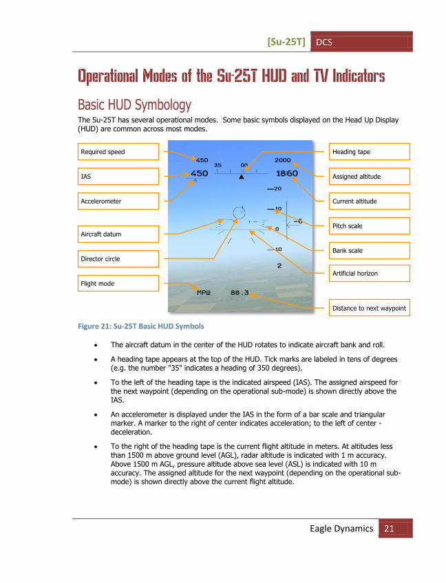
Basic HUD Symbology The Su-25T has several operational modes. Some basic symbols displayed on the Head Up Display (HUD) are common across most modes.
Figure 21: Su-25T Basic HUD Symbols
The aircraft datum in the center of the HUD rotates to indicate aircraft bank and roll.
A heading tape appears at the top of the HUD. Tick marks are labeled in tens of degrees (e.g. the number "35" indicates a heading of 350 degrees).
To the left of the heading tape is the indicated airspeed (IAS). The assigned airspeed for the next waypoint (depending on the operational sub-mode) is shown directly above the IAS.
An accelerometer is displayed under the IAS in the form of a bar scale and triangular marker. A marker to the right of center indicates acceleration; to the left of center - deceleration.
To the right of the heading tape is the current flight altitude in meters. At altitudes less than 1500 m above ground level (AGL), radar altitude is indicated with 1 m accuracy. Above 1500 m AGL, pressure altitude above sea level (ASL) is indicated with 10 m accuracy. The assigned altitude for the next waypoint (depending on the operational sub-mode) is shown directly above the current flight altitude.
Required speed
IAS
Accelerometer
Aircraft datum
Director circle
Flight mode
Heading tape
Assigned altitude
Current altitude
Pitch scale
Bank scale
Artificial horizon
Distance to next waypoint

DCS [Su-25T]
22 SU-25T COCKPIT INSTRUMENTS
When the aircraft is on the assigned flight path, the director circle is aligned with the aircraft datum in the center of the HUD. When the aircraft flies away from the assigned flight path, the director circle indicates the direction to return to it.
A pitch tape is located to the right of the aircraft datum. Aircraft pitch can be read from this tape with reference to the aircraft datum in the HUD.
To the right of the pitch tape is a vertical velocity indicator (VVI). Aircraft rate of ascent or descent between ±30 m/s is indicated by an arrow and a numeric value. The arrow stops at the VVI limit and the numeric value flashes with the vertical speed exceeds 30m/s.
The current operational flight mode is indicated in the lower left corner of the HUD.
The distance to the next waypoint in km is indicated at the bottom of the HUD.
Navigation Mode The HUD provides navigation data enroute. There are three navigation sub-modes: МРШ (ENROUTE), ВЗВ (RETURN TO BASE), ПОС (LANDING). These submodes are selected automatically at appropriate points along the assigned flight path, and can also be cycled manually by pressing the [1] key.
Figure 22: МРШ (ENROUTE) Navigation Sub-Mode
The МРШ (ENROUTE) sub-mode features a director circle displayed in the HUD. It indicates the direction to the next assigned waypoint.
The assigned altitude and airspeed enroute to the next assigned waypoint are displayed above the current altitude and airspeed in the HUD.
Director circle
Vertical velocity indicator
Next waypoint

[Su-25T] DCS
Eagle Dynamics 23
The next waypoint number is indicated in the lower right, below the pitch scale. The distance to the next waypoint is displayed at the bottom of the HUD. After arriving to the assigned waypoint is reached, the director circle automatically shows the direction to the one following, and the waypoint number in the lower right will advance.
In the ВЗВ (RETURN) sub-mode, the director circle guides the pilot to intercept the runway approach glide-slope.
The landing aerodrome can be cycled by pressing the [LCtrl-~] key. The aerodrome ID number is indicated in the lower right, below the vertical velocity scale indicator. The aerodrome control tower provides voice instructions when the aircraft approaches the runway.
Figure 23: Landing Sub-Mode
In the ПОС (LANDING) sub-mode, a glide slope error circle appears in the HUD. The aircraft is on the correct approach glide slope when the director and glide slope circles are both centered in the aircraft datum.
The director circle guides the pilot to intercept the desired glide slope. The aircraft is on the correct approach glide slope when the director and glide slope circles are both centered in the aircraft datum.
"К" and "Г" indicate the presence of localizer and glide slope beacons, respectively.
Фи0 (Fi0) - Longitudinal Aiming Close Air Combat Mode Fi0 (Phi-Zero) is the Su-25T’s main "air-to-air" combat mode for use with infrared-homing (IRH) missiles. The aiming principle is very simple - upon activating this mode with the [4] or [6] key, the
Glide slope error circle
Director circle
Localizer beam indicator
Flight mode
Vertical velocity indicator
Aerodrome ID number
Glide slope beam
indicator
Distance to selected
aerodrome
DCS [Su-25T]
24 SU-25T COCKPIT INSTRUMENTS
available R-60 or R-73 IRH missiles are automatically selected for use, and the HUD appears as shown in figure below.
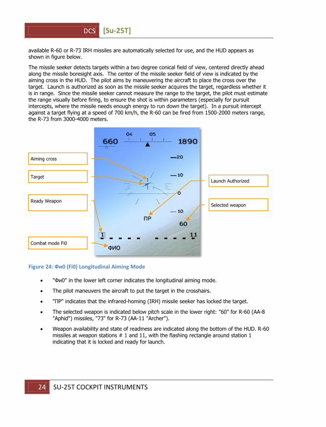
The missile seeker detects targets within a two degree conical field of view, centered directly ahead along the missile boresight axis. The center of the missile seeker field of view is indicated by the aiming cross in the HUD. The pilot aims by maneuvering the aircraft to place the cross over the target. Launch is authorized as soon as the missile seeker acquires the target, regardless whether it is in range. Since the missile seeker cannot measure the range to the target, the pilot must estimate the range visually before firing, to ensure the shot is within parameters (especially for pursuit intercepts, where the missile needs enough energy to run down the target). In a pursuit intercept against a target flying at a speed of 700 km/h, the R-60 can be fired from 1500-2000 meters range, the R-73 from 3000-4000 meters.
Figure 24: Фи0 (Fi0) Longitudinal Aiming Mode
"Фи0" in the lower left corner indicates the longitudinal aiming mode.
The pilot maneuvers the aircraft to put the target in the crosshairs.
"ПР" indicates that the infrared-homing (IRH) missile seeker has locked the target.
The selected weapon is indicated below pitch scale in the lower right: "60" for R-60 (AA-8 "Aphid") missiles, "73" for R-73 (AA-11 "Archer").
Weapon availability and state of readiness are indicated along the bottom of the HUD. R-60 missiles at weapon stations # 1 and 11, with the flashing rectangle around station 1 indicating that it is locked and ready for launch.
Aiming cross
Target
Ready Weapon
Combat mode Fi0
Launch Authorized
Selected weapon

[Su-25T] DCS
Eagle Dynamics 25
"Air-to-Surface" Weapon Mode The Su-25T aircraft can employ numerous types of "air-to-surface" weapons. This arsenal includes iron bombs, cluster bombs (CBUs), guided bombs (GBUs), submunition dispensers, aerial rockets, and guided missiles. It is one of only a few aircraft in the Russian Air Force that can employ modern precision weapons such as "Vikhr" antitank missiles with laser beam-riding guidance, Kh-25ML, Kh-29L, and Kh-29T laser- and TV-homing missiles, KAB-500KR TV-guided bombs, and Kh-25MPU and Kh-58 anti-radiation missiles
Free-fall BOMBING The category of ballistic-trajectory "free-fall" weapons includes all "iron" bombs, e.g. FAB-500, FAB-250, FAB-100, BetAB-500, and ODAB-500, RBK cluster bombs and KMGU dispensers, ZAB-500 incendiary bombs etc.
To employ free-fall weapons against ground targets, the pilot activates the "ОПТ-ЗЕМЛЯ" (GROUND) mode [7] and chooses the required free-fall bombs, cluster bombs or containers with the [D] key. Bombing symbology then appears in the HUD, including the "ОПТ-ЗЕМЛЯ" mode indicator in the lower left corner. The selected weapon is displayed in the lower right below the pitch scale, with all free-fall munitions designated as "АБ". The aim and release procedure is effectively the same for all free-fall weapons: the pilot maneuvers the aircraft to superpose the continuously computed impact point (CCIP) pipper over the target and, when all release criteria are satisfied, pulls the trigger in response to the "Launch Authorized" signal displayed in the HUD.
Figure 25: Free-Fall Bombing Mode (CCIP)
The continuously-computed impact point (CCIP) pipper indicates the impact point of the next bomb near the bottom of the HUD.
Range scale
Range bar
Current range
Weapon ready
Visual mode
Release Authorized
Bomb fall line
Chosen free-fall weapon
CCIP pipper

DCS [Su-25T]
26 SU-25T COCKPIT INSTRUMENTS
The bomb fall line extending from the impact point indicates the vertical earth axis from the pipper origin.
Free-fall ammunition is indicated by "АБ" below the pitch scale.
"Launch Authorized" indicates that all the primary release conditions such as range, altitude and velocity are satisfied and the weapon can be safely released.
"ОПТ ЗЕМЛЯ" in the lower left corner indicates the visual bombing mode.
Weapon availability and state of readiness are indicated along the bottom of the HUD. Fig. 3-59 illustrates the display when aerial bombs are suspended from the 2nd, 3rd, 4th, 8th, 9th, and 10th hardpoints. The flashing square framing hardpoint 2 indicates the ready weapon.
High drag munitions and some cluster submunitions may follow a strongly curved trajectory that puts their impact point below the lower edge of the visible HUD at almost any angle of dive, so that the CCIP pipper can not be visibly placed onto the target. In this case the continuously-computed release point (CCRP) or "invisible zone" bombing mode is used instead of CCIP.
In the CCRP mode, the pipper is visible at the extreme lower edge of the HUD. The pilot maneuvers the aircraft to place the pipper over the target, pulls the trigger and holds it pressed. The pipper becomes a fixed diamond to mark target. A director circle appears in the upper half of the HUD part to help the pilot fly the aircraft to the release point. The tip of the "keel" of the aircraft datum symbol in the HUD should be kept aligned with the center of the director circle. The pilot flies the aircraft with the trigger held depressed until the bombs are automatically released.
Figure 26: Free-Fall Bombing in the "Invisible zone" ("H3" or CCRP)
Time scale
Invisible zone mode
Director circle
Datum “keel”
Diamond target marker

[Su-25T] DCS
Eagle Dynamics 27
The range bar at the left side of the HUD becomes a time scale, indicating the number of seconds remaining before automatic bomb release. The arrow indicating the time remaining before release doesn’t begin moving until 10 seconds before release. Successful automatic release depends on strictly following the assigned flight path with the correct G-loading – the tip of the datum "keel" must be held at the center of the director circle. When the remaining time drops to zero, the bombs are released, and the pilot can let go of the trigger.
Strafing MODE The phrase "aerial rocket" is usually used to describe any unguided rockets and missiles that lack sensors and are uncontrolled after launch. These include S-5 rockets carried in the UB-32 launcher, S-8 rockets in the B-8 launcher, S-13 rockets in the UB-13, and S-24 and S-25 heavy rockets. The Su-25T’s built-in NPPU-8 includes the GSh-20 30-mm twin-barrel cannon with a 200 round ammunition magazine.
Rockets are employed by activating the "ЗЕМЛЯ" (GROUND) mode [7] and selecting the desired rocket with the [D] key.
Figure 27: Rocket Strafing Mode
The strafing pipper below the aircraft datum symbol indicates the rocket impact point.
The selected type of rocket will be displayed under the pitch scale. Figure above illustrates the "C5" symbol for the S-5 rocket.
Available weapons of the selected type are indicated along the bottom of the HUD.
ОПТ ЗЕМЛЯ (VISUAL GROUND) mode is displayed in the lower left corner.
Range bar
Current range
Ready weapon
Visual mode
Strafing pipper
Launch Authorized
Active weapon

DCS [Su-25T]
28 SU-25T COCKPIT INSTRUMENTS
To employ rockets, the pilot detects the target visually and maneuvers the aircraft into a shallow dive, placing the pipper onto the target. The maximum launch range is reached when the arrow in the range bar reaches the upper tick mark and "Launch Authorized" is displayed in the HUD.
Strafing with the built-in gun (internal cannon) is conducted by practically the same procedure. Guns are selected by activating the "ОПТ ЗЕМЛЯ" (VISUAL GROUND) mode [7] and the cannon [C].
Figure 28: ВПУ (Internal Cannon) Cannon Strafing Mode
The strafing pipper indicating the shell impact point appears under the aircraft datum.
The remaining ammunition quantity in quarters is displayed beneath the pitch scale. A full magazine is indicated with "4", the last 1/4th of remaining ammunition with "1".
"ВПУ" internal cannon mode is displayed in the lower left corner.
To use the internal cannon, the pilot detects the target visually and maneuvers the aircraft into a shallow dive, placing the pipper onto the target. The maximum firing range is reached when the arrow in the range bar reaches the upper tick mark and "Launch Authorized" is displayed in the HUD.
Precision Strike Precision "smart" weapons include "Vikhr" antitank guided missiles with laser beam-riding guidance, Kh-25ML and Kh-29L laser-homing missiles, Kh-29T TV-homing missiles and KAB-500KR TV-guided bombs. Bombs and missiles that employ TV guidance are considered "launch-and-leave" ("fire-and-forget"), since they home autonomously and do not require support from the launching aircraft after release. Laser-homing and laser beam-rider weapons require that the target be illuminated with the on-board laser during the weapon’s entire time of flight (TOF).
Launch Authorized
Current range
Built-in gun
Strafing pipper
Remaining quarters of
ammunition reserve

[Su-25T] DCS
Eagle Dynamics 29
The use of precision weapons is made possible by the onboard I-251 "Shkval" (daytime-only TV) or podded "Mercury" (LLTV for night operations) targeting systems. The image from either system is displayed on the IT-23M TV display in the upper right corner of the Su-25T control panel.
Precision weapons are employed by selecting the "ЗЕМЛЯ" (GROUND) mode [7] and activating either the onboard "Shkval" [O] or podded "Mercury" [RCtrl-O] system. The HUD will then appear as shown in figure below:
Figure 29: "Shkval" or "Mercury" Targeting System HUD
The circular laser cursor in the center of the HUD indicates the center of the optical field of view shown on the TV display, and can be slewed with the [,], [.], [/], [;] keys.
TB (TV) appears to the left of the range bar, indicating that the "Shkval" targeting system is active (НТВ (LLTV) indicates the "Mercury" system is active).
The selected weapon is indicated below the pitch scale. Figure above illustrates the 9А4172 "Vikhr" antitank missile selected. Kh-25ML (AS-10 "Karen") missiles are indicated by 25МЛ, Kh-29L (AS-14 "Kedge") by 29Л, Kh-29T (AS-14 "Kedge") by 29Т, and KAB-500KR by 500Кр.
Weapon availability and readiness state are indicated along the bottom of the HUD.
ЗЕМЛЯ (GROUND) mode is displayed in the left lower corner.
After activating the targeting system, target acquisition is accomplished by slewing the optical sensor field of view (FOV) with [,], [.], [/], [;] keys. The image is shown on the TV cockpit display. The laser cursor in the HUD will move together with the optical sensor FOV.
“Shkval” active
Stations with selected
weapon
Slewable laser cursor
ATGM
Missile launch zone reticle
DCS [Su-25T]
30 SU-25T COCKPIT INSTRUMENTS
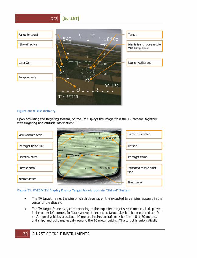
Figure 30: ATGM delivery
Upon activating the targeting system, on the TV displays the image from the TV camera, together with targeting and attitude information:
Figure 31: IT-23M TV Display During Target Acquisition via "Shkval" System
The TV target frame, the size of which depends on the expected target size, appears in the center of the display.
The TV target frame size, corresponding to the expected target size in meters, is displayed in the upper left corner. In figure above the expected target size has been entered as 10 m. Armored vehicles are about 10 meters in size, aircraft may be from 10 to 60 meters, and ships and buildings usually require the 60 meter setting. The target is automatically
Range to target
“Shkval” active
Laser On
Weapon ready
Target
Missile launch zone reticle with range scale
Launch Authorized
View azimuth scale
TV target frame size
size
Aircraft datum
Current pitch
Elevation caret
Cursor is slewable
Altitude
TV target frame
Estimated missile flight
time
Slant range

[Su-25T] DCS
Eagle Dynamics 31
locked only if the target in the cursor is within 5 meters of the expected target size, with the exception targets larger than 60 meters that can still be locked with the maximum setting of 60 m. The expected target size and cursor size are adjusted with [RCtrl-+] and [RCtrl--].
Along the top and extreme left edge of the display are azimuth and elevation scales, respectively. The viewing direction of the currently displayed image is indicated by triangular markers. The upper azimuth scale has graduated markings from -40 to +40 degrees. The elevation scale at left extends from +20 to –90 degrees.
The aircraft pitch is displayed to the right of the view elevation scale.
An aircraft datum similar to the one displayed on the HUD is duplicated at the center of the TV display. It informs the pilot about the aircraft bank while performing "head-down" targeting tasks.
The aircraft altitude above ground level (AGL) is indicated by the radio altimeter in the right upper corner of the display.
KC at the top of the display, to the left of the radio altitude, indicates that the view steering is under manual control, and no target has yet been locked.
The estimated missile time of flight (TOF) to the target in seconds is displayed in the lower right corner. After missile launch, this number indicates the time remaining until weapon impact.
The slant range to the target in kilometers, as measured by the laser rangefinder, is displayed at the bottom of the display.
Upon spotting the target, the pilot moves the laser cursor over it, and the targeting system attempts an automatic lock. To aid in target identification, the TV camera field of view (FOV) can be magnified to 23x (0.73х0.97 degrees) or an intermediate value of 8x. View magnification is controlled with [+] and [-] keys in three steps.
Figure 32: The IT-23M TV Display; Target Locked With Active Onboard "Shkval" System
View magnification
TV target frame size
Launch Authorized
Target “locked”
Target
Slant range as measured
by the laser rangefinder
DCS [Su-25T]
32 SU-25T COCKPIT INSTRUMENTS
After identifying the target to be attacked, the pilot selects the required weapon and observes the maximum launch range scale in the HUD. When the range to the target and other launch criteria are satisfied, the pilot either simply pulls the trigger for TV-guided weapons (e.g. Kh-29T missiles and KAB-500Kr bombs), or first actives the laser target illuminator for laser-guided weapons (e.g. Kh-25ML, Kh-29L and "Vikhr" missiles) by pressing [RShift-O].
The current magnification level is indicated in the upper left corner, next to the expected target size.
AC at the top of the display, next to the radio altitude, indicates that a target has been locked. The targeting system automatically corrects the view direction within the gimbal limits of ±35 in azimuth and from +15 to –85 degrees elevation to keep it pointed at the target, compensating for target and aircraft motion. The boresight direction parallel to the aircraft longitudinal axis is indicated by a long tick mark on the graduated elevation scale and the central tick mark on the azimuth scale.
With the laser range-finder active, indicated by ЛД (LASER), the slant range is shown at the bottom of the display.
"Launch Authorized" is displayed above the slant range, near the bottom of the display.
After the laser-guided missiles have hit the target, it’s necessary to deactivate the laser for cooling. The laser generates high power in the target illumination mode and can only function in this mode for a limited time. The required cooling time is approximately equal to the time the laser was working to illuminate the target. The laser automatically switches off after reaching its maximum allowable temperature. It is not recommended to use the laser for more than 20 minutes total per flight, as exceeding this limit can damage it. The ЛД symbol flashes while the laser is still cooling.
"Vikhr" missiles can be launched in pairs with a short delay between each missile, increasing the probability of hitting the target. The supersonic speed of "Vikhr" missiles can also allow multiple targets to be attacked in a single pass.
"Vikhr" missile can be also used against non-maneuvering aircraft such as helicopters and airplanes during target take-off and landing. The procedure for target acquisition is the same for aerial targets as for ground targets, taking into account that the kill probability is much lower.
Suppression of Enemy Air Defenses (SEAD Mode) The Su-25T aircraft can employ Kh-25MPU and Kh-58 antiradiation missiles (ARMs) against a variety of radio transmitter targets including surface-to-air missile (SAM) search, tracking, and target illumination radars. Since radio transmitters operate over a wide band of frequencies, not all transmitters can be targeted by all ARMs. For example, most antiradiation missiles are not designed for use against mobile anti-aircraft artillery (AAA) which use high frequency radars with short range. For more detailed information on ARM characteristics and targets against which they can be employed, see Chapter 6, "Russian Air Force Air-to-Surface Weapons."
Antiradar missiles require the Su-25T to carry the L-081 "Fantasmagoria" ARM control pod under the aircraft centerline (hardpoint #6).
Antiradiation missiles are employed by selecting the ЗЕМЛЯ (GROUND) mode [7] and activating passive radar detection with the [I] key. The pilot follows indications on the SPO-15 "Beryoza" radar warning receiver (RWR) display to steer the aircraft toward the target emitter. When the target enters the ±30 degree scan zone, a diamond target marker appears in the HUD. If the currently

[Su-25T] DCS
Eagle Dynamics 33
selected weapon is to lock and attack the detected target, a type indicator appears below the target diamond. The HUD appears as shown in figure below:
Figure 33: Suppression of Enemy Air Defenses (SEAD) Anti-Radar Mode HUD
The square-shaped antiradiation missile (ARM) cursor below the aircraft datum can be slewed over the desired target with the [,], [.], [/], [;] control keys.
The chosen weapon (58 means Kh-58) is indicated below the pitch scale.
SEAD mode (ПРГ for "anti-radiation seeker") is indicated in the lower left.
Targets are indicated as diamond markers in the HUD. Targets that can be locked and attacked by the currently selected weapon are displayed with a type indicator – P for "Patriot" SAM radar, H50 - for "HAWK" SAM radar, etc.
HAWK SAM radar marker
SEAD mode
ARM cursor
Patriot SAM radar marker
Active weapon (Kh-58
antiradiation missile)

DCS [Su-25T]
34 SU-25T COCKPIT INSTRUMENTS
Figure 34: SEAD HUD With ARM Locked Target
When target markers are visible in the HUD, the pilot designates the intended target to be attacked. The ARM cursor is moved over the intended target with the [,], [.], [/], [;] keys. The target is then locked by pressing [Enter]. The target diamond then becomes a circular marker. The range bar displays an arrow indicating the current range to the target and a tick mark indicating the maximum launch range.
The maximum weapon launch range is indicated as a tick mark on the range bar.
An arrow indicating the current range to the target moves along the range bar at the left side of the display.
When an emitting target has been selected, the diamond target marker becomes a circle.
When all launch criteria have been satisfied, the "Launch Authorized" command is displayed.
A flashing rectangle around weapon station # 5 indicates that missile is ready for launch.
When all launch criteria have been satisfied, "Launch Authorized" appears, and the pilot pulls the trigger to launch the weapon.
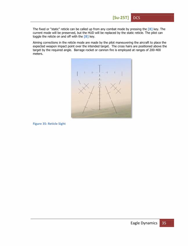
Fixed Reticle Sight The "reticle" is a backup mode, usually used for strafing when the main targeting system is damaged or accurate range data is unavailable. The reticle has calibrated scales along two axes. It is used for aiming together with previously tested and known ballistic characteristics of the selected weapon and the current flight parameters. The center of the reticle is aligned with the aircraft longitudinal axis.
Maximum launch range
Current range to the
target
Missile ready
Launch Authorized
Circular target marker
(Patriot radar)
[Su-25T] DCS
Eagle Dynamics 35
The fixed or "static" reticle can be called up from any combat mode by pressing the [8] key. The current mode will be preserved, but the HUD will be replaced by the static reticle. The pilot can toggle the reticle on and off with the [8] key.
Aiming corrections in the reticle mode are made by the pilot maneuvering the aircraft to place the expected weapon impact point over the intended target. The cross hairs are positioned above the target by the required angle. Barrage rocket or cannon fire is employed at ranges of 200-400 meters.
Figure 35: Reticle Sight

DCS [Su-25T]
36 RADIO COMMUNICATIONS AND MESSAGES
RADIO COMMUNICATIONS AND MESSAGES In the early days of air combat, communication between pilots was difficult, and often impossible. Lacking radios, early pilots were basically limited to hand signals. Coordination between pilots, especially during a dogfight, was generally impractical.
Although modern electronics have greatly improved communications capability, communications still faces some frustrating limitations. There may be dozens, if not hundreds, of combatants using any given radio frequency. When those people all try to talk at once in the heat of battle, the resulting conversations generally become jumbled, cut-off, and unintelligible. Pilots, therefore, strive to adhere to a strict radio discipline with each message, conforming to a standard Callsign, Directive, Descriptive. The "callsign" indicates who the message is intended for and who it is from, the "directive" contains brief instructions for the recipient, and the "descriptive" specifies additional information. For example:
Chevy 22, Chevy 21, hard right, bandits low 4 o’clock
This message was sent by #1 of Chevy flight to #2 of "Chevy" flight. Chevy 21 has instructed Chevy 22 to execute a hard right turn. The descriptive portion of the message explains why… there are bandits at Chevy 22’s four o’clock low position.
RADIO MESSAGES SHOULD BE BRIEF AND TO THE POINT
There are three types of radio communications in Lock On:
Radio commands that the player issues to other aircraft.
Radio messages sent to the player from other aircraft, ground controllers, etc.
Voice messages and warnings from the player’s own aircraft.
Radio Commands The following table describes the kinds of messages that the player may send and lists the key strokes needed to send each message. Depending on the type of command, it will take either two or three keystrokes to issue the desired message. There are also hot keys that allow the sending of a complex message as a single keystroke.
Message target – This column indicates who the message is intended for, and may be the entire flight, a specific wingman, an AWACS/GCI controller, or an air traffic controller.
Command – The command indicates the type of message you intend to send (such as an "Engage" command, or a "Formation" command, etc.)
Sub Command – In some cases, the sub-command specifies the exact type of command (such as "engage my target" or "Formation, line abreast.")
As illustrated in the table below, depending on the type of command, it takes either two or three keystrokes to generate the desired message. For example, to order the #3 wingman to engage the player’s target, press F3, F1, F1.

[Su-25T] DCS
Eagle Dynamics 37
Player-Generated Radio Commands
Message
Target Command
Sub
Command Definition of Command Response(s) to Command
Flight or Wingmen
Engage... My Target Player requests wingmen to attack the target that is the focus of a sensor (radar or EOS) or padlock. When the target is destroyed, wingmen will return to formation.
If wingman is capable of carrying out this command, he will respond "(x) Copy," "(x) Roger," or "(x) Affirm," where (x) is
the flight member. If wingman is incapable of carrying out command, he will respond, "(x) Negative," or "(x) Unable," where (x) is the flight member.
My Enemy Player requests wingmen to attack enemy aircraft that his attacking him.
If wingman is capable of carrying out this command, he will respond "(x) Copy," "(x) Roger," or "(x) Affirm," where (x) is the flight member. If wingman is incapable of carrying out command, he will respond, "(x) Negative," or "(x) Unable," where (x) is the flight member.
Bandints Player requests wingmen to leave formation and engage bandits (enemy aircraft) within sensor range. When the target is destroyed, wingmen will return to formation.
If wingman is capable of carrying out this command, he will respond "(x) Engaging bandit," where (x) is the flight member. If
wingman is incapable of carrying out command, he will respond, "(x) Negative," or "(x) Unable," where (x) is the flight member.
Air
Defenses
Player requests wingmen to leave formation and attack any air defense units they detect. When the target is destroyed, wingmen will return to formation.
If wingman is capable of carrying out this command, he will respond "(x) Attacking air defenses," where (x) is the flight member. If wingman is incapable of carrying out command, he will respond, "(x) Negative," or "(x) Unable," where (x) is the flight member.
Ground Targets
Player requests wingmen to leave formation and attack enemy ground targets. Valid ground targets include any structure or vehicle assigned as enemy in the mission editor. When the target is destroyed, wingmen will return to formation.
If wingman is capable of carrying out this command, he will respond, "(x) Attacking target," where (x) is the flight member. If wingman is incapable of carrying out command, he will respond, "(x) Negative," or "(x) Unable," where (x) is the flight member.
Naval Targets
Player requests wingmen to leave formation and attack any enemy naval target within sensor range. When the target is destroyed, wingmen will return to formation.
If wingman is capable of carrying out this command, he will respond, "(x) Attacking ship," where (x) is the flight member. If wingman is incapable of carrying out command, he will respond, "(x) Negative," or "(x) Unable," where (x) is the flight member.
Mission and Rejoin
Player requests that wingmen leave formation and attack the mission objective as identified in the mission editor. Once complete, the wingman will rejoin formation with player.
If wingman is capable of carrying out this command, he will respond, "(x) Attacking primary," where (x) is the flight member. If wingman is incapable of carrying out command, he will respond, "(x) Negative," or "(x) Unable," where (x) is the flight member.

DCS [Su-25T]
38 RADIO COMMUNICATIONS AND MESSAGES
Mission and RTB
Player requests that wingmen leave formation and attack the mission objective as identified in the mission editor. Once complete, the wingman will return to base.
If wingman is capable of carrying out this command, he will respond, "(x) Attacking primary," where (x) is the flight member. If wingman is incapable of carrying out command, he will respond, "(x) Negative," or "(x) Unable," where (x) is the flight member.
Flight or Wingmen
Go to… Return To Base
Wingmen will leave formation and land at their designated airfield. If no airfield is designated, they will land at the nearest friendly airfield.
If wingman is capable of carrying out this command, he will respond, "(x) Copy," "(x) Roger," or "(x) Affirm," where (x) is the flight member. If wingman is incapable of carrying out command, he will respond, "(x) Negative," or "(x) Unable," where (x) is the flight member.
Route Wingmen will leave formation and proceed to route by mission editor plan.
If wingman is capable of carrying out this command, he will respond, "(x) Copy," "(x) Roger," or "(x) Affirm," where (x) is the flight member. If wingman is incapable of carrying out command, he will respond, "(x) Negative," or "(x) Unable," where (x) is the flight member.
Hold
Position
Wingmen will leave formation and fly around current point.
If wingman is capable of carrying out this command, he will respond, "(x) Copy," "(x) Roger," or "(x) Affirm," where (x) is the flight member. If wingman is incapable of carrying out command, he will respond "(x) Negative," or "(x) Unable," where (x) is the flight member.
Flight or Wingmen
ECM… On Player requests wingman to activate ECM.
The wingman will respond, "(x) Music On," where (x) is the flight member.
Off Player requests wingman to deactivate ECM.
Wingman will respond, "(x) Music Off," where (x) is the flight member.
Flight or Wingmen
Smoke On Player requests wingman to
activate smoke containers. Wingman will activate smokes generators respond, "(x) Copy," "(x) Roger," or "(x) Affirm," where (x) is the flight member.
Off Player requests wingman to deactivate smoke
containers.
Wingman will activate smokes generators, "(x) Copy," "(x) Roger," or "(x) Affirm," where (x) is the flight
member.
Flight or Wingmen
Cover Me Player requests wingman to
attack the nearest airplane
which target is player aircraft.
Wingman will respond, "(x) Copy," "(x) Roger," or "(x) Affirm," where (x) is the flight member.
Flight or Wingmen
Jettison Weapons
Player requests wingman to jettison weapons.
If wingman is capable of carrying out this command, he will respond, "(x) Copy," "(x) Roger," or "(x) Affirm," where (x) is the flight member. If wingman is incapable of carrying out command, he will respond "(x) Negative," or "(x) Unable," where (x) is the flight member.
Flight Go
Formation
Rejoin Formation
Wingmen will cease their current task and rejoin formation with the player.
If wingman is capable of carrying out this command, he will respond, "(x) Copy rejoin," where (x) is the flight member. If wingman is incapable of carrying out command, he will respond, "(x) Negative," or "(x) Unable," where (x) is the flight member.
[Su-25T] DCS
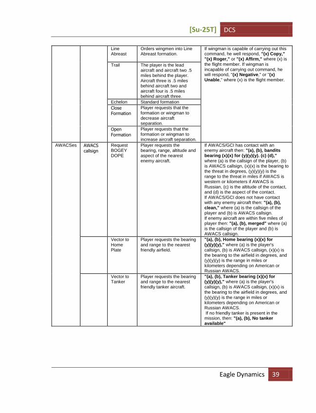
Eagle Dynamics 39
Line Abreast
Orders wingmen into Line Abreast formation.
If wingman is capable of carrying out this command, he well respond, "(x) Copy," "(x) Roger," or "(x) Affirm," where (x) is the flight member. If wingman is incapable of carrying out command, he will respond, "(x) Negative," or "(x) Unable," where (x) is the flight member.
Trail The player is the lead aircraft and aircraft two .5 miles behind the player. Aircraft three is .5 miles behind aircraft two and aircraft four is .5 miles behind aircraft three.
Echelon Standard formation
Close Formation
Player requests that the formation or wingman to decrease aircraft separation.
Open
Formation
Player requests that the formation or wingman to increase aircraft separation.
AWACSes AWACS callsign
Request BOGEY DOPE
Player requests the bearing, range, altitude and aspect of the nearest enemy aircraft.
If AWACS/GCI has contact with an enemy aircraft then: "(a), (b), bandits bearing (x)(x) for (y)(y)(y). (c) (d)," where (a) is the callsign of the player, (b) is AWACS callsign, (x)(x) is the bearing to the threat in degrees, (y)(y)(y) is the range to the threat in miles if AWACS is western or kilometers if AWACS is Russian, (c) is the altitude of the contact, and (d) is the aspect of the contact.
If AWACS/GCI does not have contact with any enemy aircraft then: "(a), (b), clean," where (a) is the callsign of the player and (b) is AWACS callsign. If enemy aircraft are within five miles of player then: "(a), (b), merged" where (a) is the callsign of the player and (b) is AWACS callsign.
Vector to Home Plate
Player requests the bearing and range to the nearest friendly airfield.
"(a), (b), Home bearing (x)(x) for (y)(y)(y)," where (a) is the player's callsign, (b) is AWACS callsign, (x)(x) is the bearing to the airfield in degrees, and (y)(y)(y) is the range in miles or kilometers depending on American or Russian AWACS.
Vector to Tanker
Player requests the bearing and range to the nearest friendly tanker aircraft.
"(a), (b), Tanker bearing (x)(x) for (y)(y)(y)," where (a) is the player's callsign, (b) is AWACS callsign, (x)(x) is the bearing to the airfield in degrees, and (y)(y)(y) is the range in miles or kilometers depending on American or Russian AWACS. If no friendly tanker is present in the mission, then: "(a), (b), No tanker available"

DCS [Su-25T]
40 RADIO COMMUNICATIONS AND MESSAGES
Request PICTURE
Player requests the bearing, range, altitude and aspect of the all enemy aircraft in zone.
If AWACS/GCI has contact with an enemy aircrafts then: "(a), (b), bandits bearing (x)(x) for (y)(y)(y). (c) (d)," where (a) is the callsign of the player, (b) is AWACS callsign, (x)(x) is the bearing to the threat in degrees, (y)(y)(y) is the range to the threat in miles if AWACS is western or kilometers if AWACS is Russian, (c) is the altitude of the contact, and (d) is the aspect of the contact. If AWACS/GCI does not have contact with any enemy aircraft then: "(a), (b), clean"
ATC - Tower
Airfield callsign
Request Taxi to Runway
Player asks tower permissioin to taxi to runway.
ATC will always respond "(a), Tower, Cleared to taxi to runway (x)(x)," where (a) is the callsign of the player and (x)(x) is the heading number of the runway.
Request Takeoff
Players asks permission from tower to takeoff.
If no aircraft are taking off from the runway and/or no aircraft are on final on that runway, then ATC will respond "(a), Tower, You are cleared for takeoff," where (a) is the callsign of the player.
Inbound Player requests permission to land at the nearest friendly airbase
"(a), (b), fly heading (x)(x), QFE, runway (y) to pattern altitude" where (a) is the player's callsign, (b) is the airbase call sign, (x)(x) is the heading, and range, QFE is a Q-code Field Elevation , (y) the heading number of the runway..
Ground Crew
Rearm… Player requests ground crew to rearm aircraft according to package selection.
Ground crew answers: "Copy ". After rearming informs: "Rearming
complete ".
Refuel… Player requests ground crew to refuel
Request repair
Player requests ground crew for repair
Complete repair is made within 3 minutes.
Other Other messages specified by mission creator via trigger events.
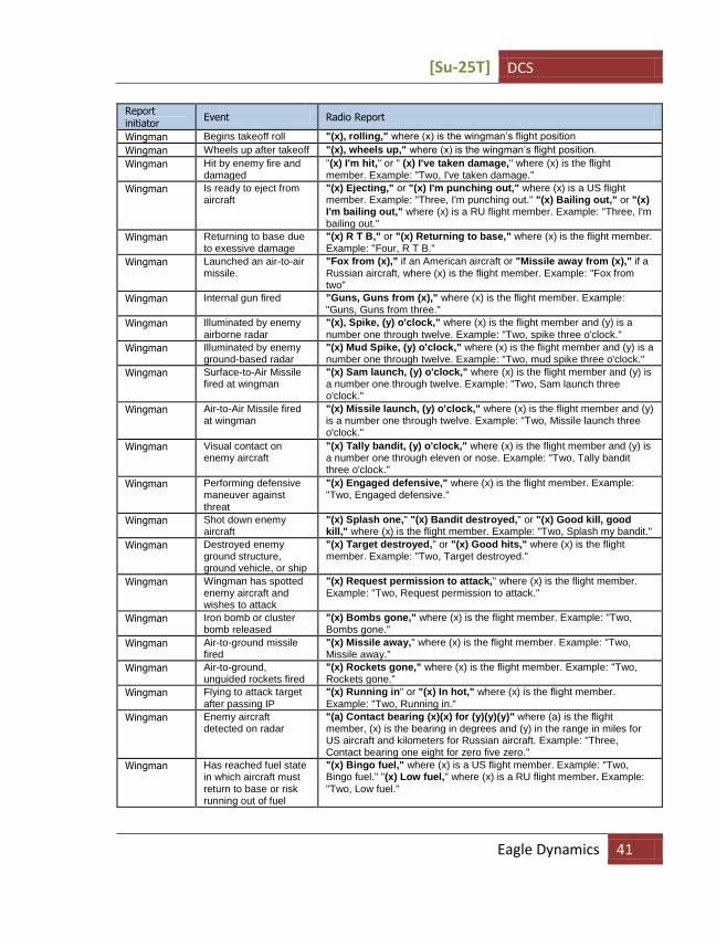
Radio Messages Communications is a two-way process; the reports from another aircraft are as important as the reports sent by the player. Such reports describe the task accomplished, or to be accomplished, by a wingman. They can also warn the player, give target designation, and provide bearings to the different objects and airbases. In table 2 is a complete list of possible reports.
Report initiator – the unit sending the report – wingmen, AWACS, tower, etc.
Event – Corresponding action of the report.
Radio Message – The message that is heard by the player.
Radio Messages
[Su-25T] DCS
Eagle Dynamics 41
Report initiator
Event Radio Report
Wingman Begins takeoff roll "(x), rolling," where (x) is the wingman’s flight position
Wingman Wheels up after takeoff "(x), wheels up," where (x) is the wingman’s flight position.
Wingman Hit by enemy fire and damaged
"(x) I'm hit," or " (x) I've taken damage," where (x) is the flight member. Example: "Two, I've taken damage."
Wingman Is ready to eject from aircraft
"(x) Ejecting," or "(x) I'm punching out," where (x) is a US flight member. Example: "Three, I'm punching out." "(x) Bailing out," or "(x) I'm bailing out," where (x) is a RU flight member. Example: "Three, I'm bailing out."
Wingman Returning to base due to exessive damage
"(x) R T B," or "(x) Returning to base," where (x) is the flight member. Example: "Four, R T B."
Wingman Launched an air-to-air missile.
"Fox from (x)," if an American aircraft or "Missile away from (x)," if a
Russian aircraft, where (x) is the flight member. Example: "Fox from two"
Wingman Internal gun fired "Guns, Guns from (x)," where (x) is the flight member. Example: "Guns, Guns from three."
Wingman Illuminated by enemy airborne radar
"(x), Spike, (y) o'clock," where (x) is the flight member and (y) is a
number one through twelve. Example: "Two, spike three o'clock."
Wingman Illuminated by enemy ground-based radar
"(x) Mud Spike, (y) o'clock," where (x) is the flight member and (y) is a number one through twelve. Example: "Two, mud spike three o'clock."
Wingman Surface-to-Air Missile fired at wingman
"(x) Sam launch, (y) o'clock," where (x) is the flight member and (y) is a number one through twelve. Example: "Two, Sam launch three o'clock."
Wingman Air-to-Air Missile fired at wingman
"(x) Missile launch, (y) o'clock," where (x) is the flight member and (y) is a number one through twelve. Example: "Two, Missile launch three o'clock."
Wingman Visual contact on enemy aircraft
"(x) Tally bandit, (y) o'clock," where (x) is the flight member and (y) is a number one through eleven or nose. Example: "Two, Tally bandit three o'clock."
Wingman Performing defensive maneuver against threat
"(x) Engaged defensive," where (x) is the flight member. Example: "Two, Engaged defensive."
Wingman Shot down enemy aircraft
"(x) Splash one," "(x) Bandit destroyed," or "(x) Good kill, good kill," where (x) is the flight member. Example: "Two, Splash my bandit."
Wingman Destroyed enemy ground structure, ground vehicle, or ship
"(x) Target destroyed," or "(x) Good hits," where (x) is the flight member. Example: "Two, Target destroyed."
Wingman Wingman has spotted enemy aircraft and wishes to attack
"(x) Request permission to attack," where (x) is the flight member. Example: "Two, Request permission to attack."
Wingman Iron bomb or cluster bomb released
"(x) Bombs gone," where (x) is the flight member. Example: "Two, Bombs gone."
Wingman Air-to-ground missile fired
"(x) Missile away," where (x) is the flight member. Example: "Two, Missile away."
Wingman Air-to-ground, unguided rockets fired
"(x) Rockets gone," where (x) is the flight member. Example: "Two, Rockets gone."
Wingman Flying to attack target after passing IP
"(x) Running in" or "(x) In hot," where (x) is the flight member.
Example: "Two, Running in."
Wingman Enemy aircraft detected on radar
"(a) Contact bearing (x)(x) for (y)(y)(y)" where (a) is the flight member, (x) is the bearing in degrees and (y) in the range in miles for US aircraft and kilometers for Russian aircraft. Example: "Three, Contact bearing one eight for zero five zero."
Wingman Has reached fuel state in which aircraft must return to base or risk running out of fuel
"(x) Bingo fuel," where (x) is a US flight member. Example: "Two, Bingo fuel." "(x) Low fuel," where (x) is a RU flight member. Example:
"Two, Low fuel."

DCS [Su-25T]
42 RADIO COMMUNICATIONS AND MESSAGES
Wingman No remaining weapons on wingman's aircraft.
"(x) Winchester," when US wingman and (x) is flight member. "(x) Out of weapons," when Russian wingman and (x) is flight member.
Wingman Enemy aircraft is behind player's aircraft.
"Lead, check six"
Wingman Player's aircraft is about to explode or crash.
"Lead, bail out"
Tower Player has come to a halt after landing on runway.
"(x), Tower, taxi to parking area," where (x) is the callsign of the aircraft. Example: "Hawk one one, Tower, taxi to parking area."
Tower Player has reached approach point and has been passed over to tower control. The runway is clear for landing.
"(x), Tower, cleared to land runway (y)(y)," where (x) is the callsign of the aircraft and (y) is the two-digit runway heading of the runway the aircraft is to land on. Example: "Hawk one one, Tower. Cleared to land runway nine zero."
Tower Player has reached approach point and has been handed over to Tower control. However, an aircraft is already in the pattern.
"(x), Tower, orbit for spacing," where (x) is the callsign of the aircraft. Example: "Falcon one one, Tower, orbit for spacing."
Tower Player is above glide path while landing
"(x), Tower, you are above glide path," where (x) is the callsign of the aircraft. Example "Eagle one one, Tower, you are above glide path."
Tower Player is below glide path while landing
"(x), Tower, you are below glide path," where (x) is the callsign of the aircraft. Example "Eagle one one, Tower, you are below glide path."
Tower Player is on glide path while landing
(x), Tower, you are on glide path," where (x) is the callsign of the
aircraft. Example "Eagle one one, Tower, you are on glide path."
Voice Messages and Warnings Computer technology has revolutionized combat aircraft; modern jets continually diagnose themselves and provide announcements, warnings, and even instructions to the pilot. In the days before women combat pilots, designers decided a woman’s voice would be immediately noticeable over the clamor of male voices flooding the airwaves.
Message Trigger – The event that prompts Betty to announce the message
Message – The exact phrase that Betty announces.
Voice Message System Messages
Message Trigger Message
The right engine is on fire. "Engine fire right"
The left engine is on fire. "Engine fire left"
Flight control systems have been damaged or destroyed. "Flight controls"
Landing gear is deployed over 250 knots. "Gear down"
Landing gear is not deployed and player is on ILS final approach. "Gear up"
The aircraft has just enough fuel to reach the closest friendly
airbase.
"Bingo fuel"
Fuel is at 1500 pounds/liters "Fuel 1500"
Fuel is at 800 pounds/liters "Fuel 800"
Radio Communications and Messages
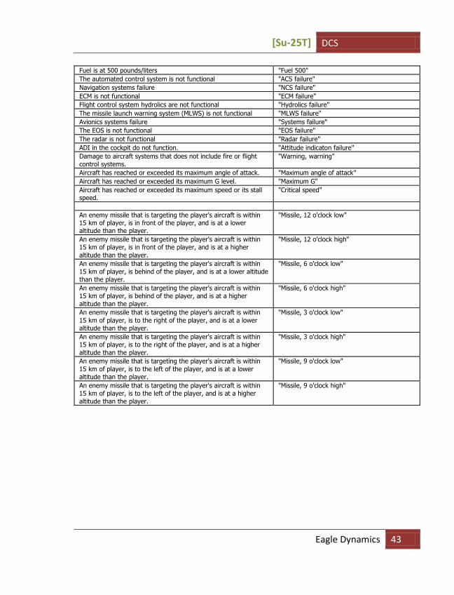
[Su-25T] DCS
Eagle Dynamics 43
Fuel is at 500 pounds/liters "Fuel 500"
The automated control system is not functional "ACS failure"
Navigation systems failure "NCS failure"
ECM is not functional "ECM failure"
Flight control system hydrolics are not functional "Hydrolics failure"
The missile launch warning system (MLWS) is not functional "MLWS failure"
Avionics systems failure "Systems failure"
The EOS is not functional "EOS failure"
The radar is not functional "Radar failure"
ADI in the cockpit do not function. "Attitude indicaton failure"
Damage to aircraft systems that does not include fire or flight
control systems.
"Warning, warning"
Aircraft has reached or exceeded its maximum angle of attack. "Maximum angle of attack"
Aircraft has reached or exceeded its maximum G level. "Maximum G"
Aircraft has reached or exceeded its maximum speed or its stall speed.
"Critical speed"
An enemy missile that is targeting the player's aircraft is within 15 km of player, is in front of the player, and is at a lower altitude than the player.
"Missile, 12 o'clock low"
An enemy missile that is targeting the player's aircraft is within 15 km of player, is in front of the player, and is at a higher
altitude than the player.
"Missile, 12 o'clock high"
An enemy missile that is targeting the player's aircraft is within
15 km of player, is behind of the player, and is at a lower altitude than the player.
"Missile, 6 o'clock low"
An enemy missile that is targeting the player's aircraft is within 15 km of player, is behind of the player, and is at a higher
altitude than the player.
"Missile, 6 o'clock high"
An enemy missile that is targeting the player's aircraft is within
15 km of player, is to the right of the player, and is at a lower altitude than the player.
"Missile, 3 o'clock low"
An enemy missile that is targeting the player's aircraft is within 15 km of player, is to the right of the player, and is at a higher
altitude than the player.
"Missile, 3 o'clock high"
An enemy missile that is targeting the player's aircraft is within
15 km of player, is to the left of the player, and is at a lower altitude than the player.
"Missile, 9 o'clock low"
An enemy missile that is targeting the player's aircraft is within 15 km of player, is to the left of the player, and is at a higher
altitude than the player.
"Missile, 9 o'clock high"

DCS [Su-25T]
44 SU-25T ADVANCED FLIGHT DYNAMICS MODEL
SU-25T ADVANCED FLIGHT DYNAMICS MODEL Adwanced flight dynamics model was created for the Su-25 and Su-25T. This section describes some of the many remarkable features of the advanced flight model.
Aircraft dynamics are calculated on the basis of the same physics equations describing translational and rotational motion of a solid body under the influence of external forces and moments, disregarding the nature of their origin.
Trajectory and angle movements look more natural due to correct modeling of the aircraft’s inertial properties.
Transitions between the flight modes in a smooth manner without abrupt changes of angle rotational speeds and attitude (for example: after a tail-slide or when landing with an angle of roll on one landing wheel).
Gyroscopic effect with the aircraft’s rotation taken into account.
The asymmetric effect of external forces is taken into account, along with the effect of external forces not going through the center-of-gravity (for example: engine thrust, drag chute forces). These forces are correctly modeled at any flight mode and cause an adequate rotary moment.
The center-of-gravity can change its location within the speed axis system.
The modeling of lateral and longitudinal center of mass has been introduced. This can change depending on fuel load and weapon loads.
The asymmetrical loading of weapon and fuel pylons, which influence the characteristics of lateral control (depending on flight speed, regular overload, etc), is also modeled.
When calculating aerodynamic characteristics, the aircraft is represented as a combination of airframe components (fuselage, outer wing panel, stabilizer, etc). Separate calculations for the aerodynamic performance each of these components is performed. This is done over the entire range of local angles of attack and slip (including supercritical), local dynamic pressure and Mach number. This takes into consideration the change and level of destruction of control surfaces and various airframe components.
Aerodynamics are accurately modeled in the entire range of angles of attack and glide.
The efficiency of lateral control, and degree of lateral and static lateral stability, now depend on the angle of attack, longitudinal and lateral center-of-gravity.
The wing autorotation effect when performing a rolling rotation at high angles of attack is modeled.
Kinematic, aerodynamic and inertial interaction of longitudinal, dihedral and lateral channels (yaw movement when performing a rolling turn, rolling motion at rudder pedal forward, etc).
Angle of glide availability is determined by the pilot’s efforts and the plane’s position.
[Su-25T] DCS
Eagle Dynamics 45
When an airframe component is destroyed, the plane’s motion is modeled in a natural way. The damaged component’s aerodynamics can be fully or partially removed from the aircraft’s aerodynamic calculations.
The flight model guarantees a realistic implementation of stalls (rocking wings with simultaneous course oscillation).
Various characteristics of aerodynamic shaking depending on the flight mode have been introduced. This occurs due to store loading, exceeding allowable angle of attack, Mach number, etc.
The jet engines are represented as a complex model of the main components: compressor, combustion chamber, turbine and starter-generator.
Idle RPM depends on the speed mode: altitude and Mach number, weather conditions: pressure and temperature.
Low RPM over-speeding is modeled.
Engine throttling and its controllability depend on rotation speed.
Gas temperature behind the turbine is dependent on engine operating mode, flight mode and weather condition.
Specific fuel consumption is non-linearly dependent on engine operating mode and flight mode.
The dynamics of engine operating parameters (gas speed and temperature) during engine start and shut down is accurately modeled. The mode of engine autorotation from ram airflow, engine seize (accompanied by continued temperature rise) in case of engine start at the incorrect throttle position, engine restart and windmill air restart.
The left and right hydraulic system model includes models of sources and consumers of hydraulic pressure.
Each hydraulic system supplies its own group of hydraulic pressure users (landing gear, aileron actuator, flaps, wing leading edge flaps, adjustable stabilizer, nose wheel steering, brake system, etc).
Pressure in the left and right hydraulic systems depends on the balance of hydraulic pump efficiency and operating fluid consumption by hydraulic pressure users (boosters, actuators, etc). Hydraulic pumps efficiency depends on the right and left engines speed respectively, operating fluid consumption depends on their work intensity.
Both catastrophic and partial hydraulic actuators failure when pressure drops in a corresponding hydraulic system is modeled.
The control system includes models of the primary components: trimming mechanism and trimming effect, hydraulic boosters in roll channel, and yaw dampener.
Pitch trimming, the yawing model and the aileron trimming mechanism model are all based on a different logics. In particular, the pitch trimming position does not influence rate controller position at near-zero flight speed. Trimming tab serviceability depends on electrical power in the aircraft electrical system.

DCS [Su-25T]
46 SU-25T ADVANCED FLIGHT DYNAMICS MODEL
In the event of pressure drop in the left side of the fuselage, lateral control worsens with the rise of indicated flight airspeed. Longitudinal control does not depend on fuselage pressure.
The extension and retraction speed of high-lift wing and adjustable stabilizer surfaces depends on fuselage pressure.
The extension of high-lift wing devices for a more maneuverable configuration at a high indicated airspeed can lead first to partial and then to complete hydraulic actuator blocking. This causes fuselage pipe damage, hydraulic fluid leakage and fuselage pressure drop.
Landing gear extension at a high indicated airspeed can first lead to partial and then to complete hydraulic actuator blocking. This causes fuselage pipe damage, hydraulic fluid leakage and fuselage pressure drop.
Cold Engine Start Procedure From the Parking Ramp 1. Turn on the auxiliary power unit (APU) with the [RShift-L] key and confirm that all
instrument indications on the dash and HUD are operating normally.
2. Set the throttles to the idle position.
3. Start both engines with the [RShift-Home] key, or sequentially start the right engine - [RCtrl-Home] key and then left engine - [RAlt-Home] key.
4. Check engine compressor fans turning on the tachometer indicator and engine RPM stabilizes at 33%.
5. Check the turbine gas temperature on the exhaust gas indicator. The exhaust gas temperature should be around 440 degrees.
If you start the engine with the throttles not set to idle, the engine will be flooded with fuel and the engine will be held-up in an intermediate position. An uncontrollable engine temperature rise may also result and start an engine fire.
In such a situation, immediately stop the engine(s) - [RShift-End]. After a full engine shut-down, wait one to five minutes for the engine to cool off, and then to repeat the startup procedure.
To speed up the engine start procedure it is also possible to perform an engine relight. To do this, wait for the second stage of the engine spin-up to reach at least 16% RPM; then move the throttles to their maximum thrust position.
In Air Automatic engine start If the engines cease to function (flame out) while in the air, you can perform an automatic restart. To do so, the airspeed must exceed 150 km/h; set the throttle to the idle position; then increase to the maximum thrust; and then back to idle. If all conditions are met, the engine will begin the restart process.
A windmill start is only possible when engine speed is at or above 12%.

[Su-25T] DCS
Eagle Dynamics 47
Special Considerations for Flying the Su-25T
Taxi Nosewheel turns should be performed at no faster than 5-10 km/h in order to avoid rolling the aircraft onto its wing or damaging the nose gear pneumatics.
Take-off The wheel brakes will hold the aircraft at no greater than 80% of engine RPM. When powering up the engines for take-off, release the wheel brakes as the RPM climb through 70-75% and increase thrust to full military power as the aircraft begins to roll for take-off. Maintain heading straight down the runway with soft pedal input. As the speed climbs to 160-180 km/h for normal take-off weight or 200-220 km/h for maximum take off weight, pull the stick back about 2/3 of the way to raise the nose for take-off. A good take-off pitch angle can be approximated by placing the ends of the two pitot tubes along the horizon. The aircraft will take-off almost immediately as you raise the nose to a proper take-off angle. If the aircraft is not carrying external stores, it will have a tendency to increase pitch dynamically, which can be countered by carefully pushing the stick forward.
Retract the gear at 10 m. above the ground and the flaps as the airspeed climbs to 320-340 km/h at an altitude of no less than 150 m. As the gear is raised, the hydraulic pressure may temporarily drop in the second hydraulic system, activating the "ГИДРО 2" ("HYDRO-2") warning light.
Crosswind Take-off One of the peculiar features of the Su-25/25T is the short span and base of the landing gear, which makes crosswing take-offs and landings quite challenging. Nevertheless, the aircraft can be held steady while rolling in a crosswind of up to 11-14 m/s, provided the ruway is dry. When rolling in a crosswind, the aircraft will tend to bank with the wind, which can be corrected by counter stick force against the wind. The aircraft will also have a tendency to turn into the wind, which can be corrected with smooth pedal input in the opposite direction.
Landing On approach, the gear should be extended once the airspeed falls below 400 km/h. When extending the flaps, the aircraft will have a tendency to "balloon". The aircraft balance in the Take-off/Landing Configuration is almost identical to normal Flight Configuration. If the aircraft becomes unbalanced in either its longitutional or lateral axis when configured for landing, the gear or flaps may not have fully extended or extended asimetrically. In this case, retract the flaps to perform the landing in normal Flight Configuration. Adjust all approach and landing speeds to increase by 40-60 km/h.
Careful speed management is required on final approach to perform a proper landing. Reduce speed to 290-310 km/h by setting the aircraft into Takeo-off/Landing Configuration at the start of your glideslope descent. Reduce speed to 260-280 km/h by the time you reach the Inner Marker Beacon. Begin to flare as you approach the runway, at approximately 5-8 m. altitude, 250-270 km/h and 100 m. before the runway threshold. After final line up at approximately 1 m. above the ground, reduce thrust to Idle and as the aircraft slows down, increase pitch by holding the stick back so that the pitot
DCS [Su-25T]
48 SU-25T ADVANCED FLIGHT DYNAMICS MODEL
tubes line up with the horizon. Touchdown should occur at 220-240 km/h. Proceed to lower the nose wheel by carefully pushing the stick forward, release the brake chute and engage the wheel brakes. Maintain heading down the runway centerline with smooth pedal inputs. If the aircraft veers when braking, release the brakes, correct heading and only then reapply the brakes. If the aircraft risks running off the runway at a speed of greater than 50 km/h, retract the gear, open the canopy, and perform an emergency shut down.
Crosswind Landing When performing a crosswind landing, estimate a lead angle directly to the runway threshold such that the approach can be flown with no bank or yaw. As you flare the aircraft just before touchdown, eliminate the lead angle to align the aircraft with the runway and push the stick into the wind. This will ensure that touchdown is performed with no sideslip and is corrected for the crosswind bank tendency when rolling on the runway. Once the main gear is in contact with the ground, release the pedals to center the nose wheel and quickly, but carefully lower the nose to touchdown the nose wheel. Once stabilized down the runway centerline, engage the wheel brakes. In a crosswind of greater than 4-5 m/s, the brake chute is not used as it would make it practically impossible to maintain the aircraft on the ruway. If the aircraft veers when braking, release the brakes, correct heading and only then reapply the brakes.
Common Landing Errors
Overshoot An overshoot will occur if speed was mismanaged and the approach performed too fast or if the touchdown point was miscalculated. This will often happen when the flare is performed late, such as over the runway threshold instead of ahead of it. A significant overshoot can be dangerous and the landing should be aborted as a missed approach ("go-around").
Landing Short A landing short will occur if the approach speed was too low, the flare maneuver started too early, or the aircraft was allowed to fall below the glidepath on final appoach. To correct this, increase engine thurst until optimum approach speed is reached and the aircraft is on the glidepath.
Flare Too High A flare too high will occur if the flare altitude is misjudged or the stick is pulled back too much during the flare. To correct this, hold the stick steady to allow the aircraft to descend to the proper flare altitude and then pull the stick again to perform a proper flare. In a flare too high, the aircraft will likely loose airspeed and drop onto the runway, resulting in a rough touchdown and high vertical velocities stressing the airframe.
Stalls and Spins If airspeed is lost in level flight, the aircraft will stall without entering a spin. It will begin a "parachute" descend while oscillating in yaw and roll. If the stick is pulled during the stall, oscillations

[Su-25T] DCS
Eagle Dynamics 49
may increase in roll to the point of causing a wing-over, where the aircraft will roll violently toward one side. To correct this and counteract the stall, push the stick forward.
When flying in normal Flight Configuration and Maneuvering Configuration, a spin can only be induced intentionally. In normal Flight Configuration and Maneuvering Configuration, the spin will be alleviated once the stick is placed into its neutral position. To expedite the recovery out of the spin, the standard technique is to push the stick forward and apply opposite rudder.
When flying in Take-off/Landing Configuration, a spin can be entered unintentionally if the angle of attack reaches beyond critical limits, especially if the aircraft’s center of gravity is aft of center. The CG will shift aft in an Su-25 if the cannon ammunition has been expended and is always aft in the Su-25T. Once the aircraft has entered a spin in this configuration, it is practically impossible to recover.
DCS [Su-25T]
50 WEAPONS DELIVERY
WEAPONS DELIVERY To employ a weapon, the pilot needs to execute the following steps:
Detect the target
Lock or designate the target
Deploy weapon
Su-25T The Su-25T is the perfect tactical attack aircraft for the Russian Air force. It can strike small, mobile targets with pinpoint accuracy in all weather conditions and at all times of day.
The Su-25T is equipped with the I-251 "Shkval" TV targeting system, combined with the "Prichal" laser range-finder/target designator. For nighttime operations it can be equipped with the "Mercury" low light level TV (LLTV) targeting system.
For self protection, the Su-25T can also carry the R-73 and R-60 short range missiles.
Air-to-Air Weapons
R-73 and R-60 short range missiles The Su-25T can carry the R-73 and R-60 short range air-to-air missiles in the longitudinal aiming mode. When this mode is activated, the missile’s seeker has a scan zone of 2 degrees that is directed forward along the aircraft’s longitudinal axis. The target must enter this seeker field of view, which is represented by the center of the aircraft symbol on the HUD, to automatically lock the target.
The target lock and launch procedures consist of the following steps:
Step 1
Select air-to-air mode with the [6] key. In either case, longitudinal aiming mode will be activated.
Step 2
Maneuver your aircraft to place the center of the HUD aircraft symbol over the target. When the missile seeker is in lock range, the aiming will jump to the target; the yellow launch authorized lamp will flash; and a lock audio signal will sound. The lock range depends greatly on the target’s IR-signature. The maximum signature for an aircraft is when flying at high-altitude, at full AB, and you are in the target’s rear-hemisphere. Note that helicopters have minimal IR signatures and they may be difficult to acquire. When the missile seeker achieves a lock and the "LA" message is displayed on the HUD, this is only an indication that the target has been locked; it does not mean that the target is within range of the missile. Launching a missile too early may lead to a miss because the missile has insufficient energy to intercept the target. It is recommended that you not launch until the target’s shape is visible or 2 km.

[Su-25T] DCS
Eagle Dynamics 51
Step 3
Press the trigger on your joystick or press the [Space] key to launch the missile. The missile is "fire and forget" and requires no additional support from the launch aircraft.
Internal Gun and Gun Pods Application Against Air Targets The internal gun and gun pods can be used against air targets, but it has limited accuracy in application.
Step 1
Identify the target visually.
Step 2
Select air-to-air mode by pressing [6] key. Select internal gun or gun pods by pressing the [C] key. Now in gun mode, the funnel will appear on the HUD - graphically it represents the shell’s flight trajectory vs. target wingspan. By pressing the [RAlt--] and [RAlt-+] keys, you can set the target wingspan (also known as "target base") in meters. The target’s set wingspan is indicated in the upper portion of the HUD.
Step 3
Maneuver your aircraft to place the target inside the funnel such that the target’s wingtips touch the funnel edges. Press the weapon release button on your joystick or [Space] key on your keyboard to fire.
Effective fire is generally below 800 meters. For better accuracy, try to maneuver in the same plane as your target. The gun funnel is most accurate when used from behind the target.
Air-to-Ground Weapons The Su-25T can carry a wide variety of weapon types, including unguided bombs, sub-munitions containers and dispensers, unguided rockets, TV-guided missiles, laser and beam-riding homing missiles, TV-guided bombs, and gun pods.
Unguided, Low-Drag Bombs This category bomb includes the FAB-100, FAB-250 and FAB-500 unguided bombs. They have low drag indexes and flat trajectories. This often allows you to release a bomb at a target while it is still visible.
Step 1
Identify the target visually.
Step 2
Switch to air-to-ground mode by pressing the [7] key. Select the weapon to be released using the weapon control panel and the [D] key. The ripple quantity should be selected on the panel with the [LCtrl-Space] key and the release interval with the [V] key.
Step 3

DCS [Su-25T]
52 WEAPONS DELIVERY
When the aiming mark starts moving up from the lower portion of the HUD, fly the aircraft to place the aiming mark on the target. When the aiming mark is showing the true impact point underneath it and the bomb can be dropped, the orange lamp will light. To release a bomb, press the weapon release button on your joystick or press the [Space] key. If a bomb ripple setting has been made, keep the weapon release button held down until the pulse ends.
BOMBS CAN BE RELEASED ONCE THE "LA" MESSAGE APPEARS ON THE HUD. BEFORE BOMB RELEASE, ENTER A
WINGS-LEVEL DIVE TO A POINT JUST BEYOND YOUR TARGET. ANY DEVIATIONS IN BANK, PITCH OR YAW AND
SIGNIFICANT AIRSPEED CHANGES WILL LEAD TO INACCURATE BOMB IMPACTS
Unguided, High-Drag Bombs This bomb category includes bombs with aerodynamically high drag, such as various RBK types, KMGU-2 containers, and BetAB concrete-piercing bombs. They have high drag values and have a curved trajectory that significantly complicates that targeting of visible targets.
It is recommended to use the continuously calculated release point (CCRP) delivery mode when using this type of bomb. To drop a high-drag bomb, follow these steps:
Step 1
Identify the target visually.
Step 2
Select the air-to-surface mode by pressing the [7] key.
Step 3
Place the CCRP pipper on the intended target and press and hold the weapon release button on the joystick or the [Space] key on the keyboard. The WCS will initiate the release point calculation, and on the HUD will appear a diamond symbol that represents the designation point. In the upper portion of the HUD, a steering ring will be displayed. Fly the aircraft such that the aircraft symbol "tail" is placed in the center of this ring. The range scale on the right side of the HUD turns into a time-to-release scale that is graduated in seconds. The arrow indicating time-to-release will appear on the scale only 10 seconds before the bombs release. For accurate bombing it is best to minimize changes in bank and yaw. When the timer reaches zero, the bomb(s) will automatically be released and you can release the trigger.
Step 4
Press the trigger on your joystick or press the [Space] key
TV Targeting Aided Bombing Unguided bombs can be used in conjunction with the "Shkval" TV targeting system or the "Mercury" low-light level TV targeting system.
Bomb delivery using these sensors is done as follows:
Step 1
Select air-to-ground mode by pressing the [7] key. Select the desired bomb by pressing the [D] key. Confirm the selected bomb type on the HUD. To detect and identify targets, you must turn on the
[Su-25T] DCS
Eagle Dynamics 53
"Shkval" TV targeting system by pressing the [O] key, or the "Mercury" system by pressing the [RCtrl-O] key. Search for your target by moving the scan zone center with the [;], [,], [.], [/] keys. Upon target acquisition, ground-stabilize the sensor by pressing the [Enter] key. For positive target identification you can increase the sensor’s magnification level by pressing the [+] and [-] keys.
Step 2
Place the acquisition frame on the target. Fly the aircraft in the direction to the target and turn on the laser range-finder/target designator by pressing the [RShift-O] key.
Step 3
Press the weapon release button on your joystick or the press the [Space] key on your keyboard. The WCS will initiate the release point calculation, and on the HUD will appear a diamond symbol that represents the designation point. In the upper portion of the HUD, a steering ring will be displayed. Fly the aircraft such that the aircraft symbol "tail" is placed in the center of this ring. The range scale on the right side of the HUD turns into a time-to-release scale that is graduated in seconds. The arrow indicating time-to-release will appear on the scale only 10 seconds before the bombs release. For accurate bombing it is best to minimize changes in bank and yaw. When the timer reaches zero, the bomb(s) will automatically be released and you can release the trigger.
Step 4
Turn off the laser range-finder by pressing the [RShift-O] key. Remember that the range-finder/target designator has a limited, continuous duration time, which is about one minute. After that, the device needs time to cool down or risk damage. During this cool-down time indicated by "Л", a green lamp will flash at 2 Hz; when the device has sufficiently cooled, the lamp will extinguish. The cooling time is nearly equal to the work time, and it depends on environment temperature conditions.
The KMGU-2 sub-munitions dispensers differ in that it’s required to offset the aiming point from the target to allow the container’s rotary clam-shell time to open.
Unguided Rockets and Internal Gun Unguided rockets include all the rockets and missiles that are not equipped with guidance system. These include the S-5 in the UB-32 rocket launcher, the S-8 in the B-8 rocket launcher, the S-13 in the UB-13 rocket launcher, and the S-24 and S-25. The internal gun is the GSh-301 30-mm gun with 150 rounds.
Step 1
Identify the target visually.
Step 2
Select the air-to-surface mode by pressing the [7] key and cycle the [D] key until the rocket of choice is selected. Or, select the [C] to make the gun the active weapon. Confirm that the correct weapon is selected on the HUD. Maneuver into a shallow dive towards the target.
Step 3

DCS [Su-25T]
54 WEAPONS DELIVERY
When the aiming pipper is over the target and launch conditions are satisfied, the "LA" message will appear on the HUD. Fire the rocket(s) or guns by pressing the weapon release button on your joystick or by pressing the [Space] key on your keyboard.
Gun Pods The Su-25 can carry SPPU-22-1 gun pods that can operate in zero depression angle mode, fixed depression angle mode, and programmed (point tracking) mode.
Because the zero depression mode does not differ the internal gun, we shall only review two modes: fixed depression and programmed.
THE FIXED DEPRESSION MODE IS USED WHEN FIRING IN HORIZONTAL FLIGHT ALONG A LINE OF TARGETS
Step 1
Identify the target visually.
Step 2
Switch to the air-to-ground mode by pressing the [7] key. Select internal gun mode by pressing the [C] key.
Select gun pods by pressing the [RCtrl-Space] key and confirm weapon selection on the HUD and WCS panel; two gun pods will be selected. Set the ripple interval/gun pods mode to FIX mode and the ripple quantity switch to PO2.
If the aircraft has four gun pods loaded onboard, press [RCtrl-Space] once more. Set the ripple interval/gun pods mode to FIX mode and the ripple quantity switch to PO2.
Step 3
Using the [RAlt--] and [RAlt-+] keys, alter the barrel depression angle by moving the aiming mark along the vertical axis on HUD.
Step 4
Align your flight path with the target and maintain the level flight. When the aiming mark on the HUD overlays the target, press the weapon release button on your joystick or press the [Space] key on your keyboard to fire.
While firing, you use rudder input to cover a larger area with fire. Note though that any deviations in bank angle can lead to significant shell deviation.
THE PROGRAMMED MODE IS USED FOR THE PINPOINT ATTACKS AGAINST LIGHTLY ARMORED TARGETS.
Step 1
Identify the target visually.
Step 2
Switch to the air-to-ground mode by pressing the [7] key. Select internal gun mode by pressing the [C] key.

[Su-25T] DCS
Eagle Dynamics 55
Select gun pods by pressing the [RCtrl-Space] key and confirm weapon selection on the HUD and WCS panel; two gun pods will be selected. Set the ripple interval/gun pods mode to FIX mode and the ripple quantity switch to PO2.
If the aircraft has four gun pods loaded onboard, press [LCtrl-Space] once more. Set the ripple interval/gun pods mode to FIX mode and the ripple quantity switch to PO2.
Step 3
Using the [RAlt--] and [RAlt-+] keys, alter the barrel depression angle by moving the aiming mark along the vertical axis on HUD.
Step 4
Turn on the laser range-finder by pressing the [RShift-O] key. Set the interval/gun pods mode switch to PROGR mode.
Step 5
In a wings-level dive, place the aiming mark on the target and, when "LA" message appears, open fire by pressing the weapon release button on your joystick or by pressing the [Space] key on your keyboard. Avoid roll, pitch, and yaw changes while firing for better accuracy.
Step 6
Turn off the laser range-finder/target designator by pressing the [RShift-O] key.
TV-Guided Bombs and Missiles The Su-25T is equipped to carry the KAB-500Kr bomb and Kh-29T missile with the "Tubus" optical seeker. Such weapons allow "fire-and-forget" attacks that do not require the launch aircraft to continue locking the target after the weapon has been launched. These unguided weapons are designed to destroy buried command centers, control centers, reinforced concrete shelters and other well-protected targets. Kh-29T missile can also be used to destroy ships.
The most significant limitation of TV-guided weapon is the inability to use them at night or during poor weather conditions.
The delivery procedure for such weapons is as follows:
Step 1
Select air-to-ground mode by pressing the [7] key. Select the desired bomb by pressing the [D] key. Confirm the selected bomb type on the HUD. To detect and identify targets, you must turn on the "Shkval" TV targeting system by pressing the [O] key, or the "Mercury" system by pressing the [RCtrl-O] key. Search for your target by moving the scan zone center with the [;], [,], [.], [/] keys. Upon target acquisition, ground-stabilize the sensor by pressing the [Enter] key. For positive target identification you can increase the sensor’s magnification level by pressing the [+] and [-] keys.
Step 2
To lock a target, you need to manually set a specified size (also known as "target base") of the target correctly. By default, target specified size is 10 m. It is recommended to use the following target base values:
DCS [Su-25T]
56 WEAPONS DELIVERY
Personnel and minor structures – 5 m.
Cars and armored vehicles – 10 m.
Tactical aircraft and helicopters – 20 m.
Transport and strategic aircraft – 30–60 m.
Buildings – 20–60 m.
Ships – 60 m.
The "Shkval" targeting system will lock on to the nearest object within the acquisition frame that has dimensions comparable with the set target size. If the incorrect object is locked, move the acquisition frame to the correct target with the [;], [,], [.], [/] keys.
When a target is locked, an "AC" message will appear on the TV monitor – auto-tracking.
Step 3
Range to target is indicated by the range scale displayed on the HUD. When the maximum launch range is reached and the "LA" message appears, release the weapon by pressing the weapon release button on your joystick or by pressing the [Space] key on your keyboard.
After release/launch, you can immediately begin another task.
Note that it is impossible to deliver TV-guided weapons in poor visibility conditions and at night; they only work in the visible light spectrum and are influenced by all the limitations associated with daytime TV-devices. To lock a target, the target must be illuminated by a natural or artificial light source.
Laser Designation Missiles The Su-25T can use the Kh-29L and Kh-25ML laser designation homing missiles. The Kh-29L and Kh-25ML were designed to destroy buried command centers, control centers, reinforced concrete shelters and structures, antiaircraft artillery positions, artillery, and other protected targets.
The delivery procedure for such weapons is as follows:
Step 1
Select air-to-ground mode by pressing the [7] key. Select the desired weapon by pressing the [D] key. Confirm the selected weapon type on the HUD. To detect and identify targets, you must turn on the "Shkval" TV targeting system by pressing the [O] key, or the "Mercury" system by pressing the [RCtrl-O] key. Search for your target by moving the scan zone center with the [;], [,], [.], [/] keys. Upon target acquisition, ground-stabilize the sensor by pressing the [Enter] key. For positive target identification you can increase the sensor’s magnification level by pressing the [+] and [-] keys.
Step 2
To lock a target, you need to manually set a specified size (also known as "target base") of the target correctly. By default, target specified size is 10 m. It is recommended to use the following target base values:
Personnel and minor structures – 5 m.

[Su-25T] DCS
Eagle Dynamics 57
Cars and armored vehicles – 10 m.
Tactical aircraft and helicopters – 20 m.
Transport and strategic aircraft – 30–60 m.
Buildings – 20–60 m.
Ships – 60 m.
The "Shkval" targeting system will lock on to the nearest object within the acquisition frame that has dimensions comparable with the set target size. If the incorrect object is locked, move the acquisition frame to the correct target with the [;], [,], [.], [/] keys.
When a target is locked, an "AC" message will appear on the TV monitor – auto-tracking.
Step 3
Turn on laser range-finder by [RShift-O] key. Range to target is indicated by the range scale displayed on the HUD.
When the maximum launch range is reached and the "LA" message appears, release the weapon by pressing the weapon release button on your joystick or by pressing the [Space] key on your keyboard.
Step 4
Take note if the target was destroyed by the missile. If not and range to target still permits, launch another missile. Remember that you must lock the target the entire time the missile is in flight. If the lock is broken prior to the missile reaching its target, the missile will most likely miss. When locked to target, restrict your maneuvering as this could bring the target outside the gimbal limits of the "Shkval" targeting system.
Step 5
Turn off the laser range-finder by pressing the [RShift-O] key. Remember that the range-finder/target designator has a limited, continuous duration time, which is about one minute. After that, the device needs time to cool down or risk damage. During this cool-down time indicated by "Л", a green lamp will flash at 2 Hz; when the device has sufficiently cooled, the lamp will extinguish. The cooling time is nearly equal to the work time, and it depends on environment temperature conditions.
The "Vikhr" has limited capabilities against low-speed air targets such as helicopters and low-speed aircraft. Engagement of air targets is the same as described above. However, the launch range against air targets, especially in a pursuit courses, significantly drops. Use the "Vikhr" against air targets less than 3 – 5 km away, depending on the target speed and aspect angle.
Laser Beam-Riding Missiles The Su-25T can use the "Vikhr" laser beam-riding missile. The "Vikhr" is a specialized antitank missile (ATGM) designed to destroy mobile armored units.
The delivery procedure for such weapons is as follows:
Step 1

DCS [Su-25T]
58 WEAPONS DELIVERY
Select air-to-ground mode by pressing the [7] key. Select the ATGMs by pressing the [D] key. Confirm the selected weapon type on the HUD. To detect and identify targets, you must turn on the "Shkval" TV targeting system by pressing the [O] key, or the "Mercury" system by pressing the [RCtrl-O] key. Search for your target by moving the scan zone center with the [;], [,], [.], [/] keys. Upon target acquisition, ground-stabilize the sensor by pressing the [Enter] key. For positive target identification you can increase the sensor’s magnification level by pressing the [+] and [-] keys.
Step 2
To lock a target, you need to manually set a specified size (also known as "target base") of the target correctly. By default, target specified size is 10 m for armored targets.
The "Shkval" targeting system will lock on to the nearest object within the acquisition frame that has dimensions comparable with the set target size. If the incorrect object is locked, move the acquisition frame to the correct target with the [;], [,], [.], [/] keys.
When a target is locked, an "AC" message will appear on the TV monitor – auto-tracking.
Step 3
Turn on laser range-finder by [RShift-O] key. Range to target is indicated by the range scale displayed on the HUD.
Figure 36: ATGM delivery
Upon reaching maximum launch range, maneuver the aircraft to position the target marker within the missile launch zone reticle. Once aiming is complete, the target line-of-sight symbol will be within the missile launch zone reticle.
When the "LA" message appears, release the weapon by pressing the weapon release button on your joystick or by pressing the [Space] key on your keyboard.
Target marker
Missile launch zone reticle
with range indicator
Launch Authorized
[Su-25T] DCS
Eagle Dynamics 59
Step 4
Take note if the target was destroyed by the missile. If not and range to target still permits, launch another missile. Remember that you must lock the target the entire time the missile is in flight. If the lock is broken prior to the missile reaching its target, the missile will most likely miss.
While the missile is in flight, maintain the aircraft’s current heading such that it does not exceed the Shkval’s angular gimbal limits. Try to avoid high angular velocity that can cause missile to lose the laser-guidance beam.
Step 5
Turn off the laser range-finder by pressing the [RShift-O] key. Remember that the range-finder/target designator has a limited, continuous duration time, which is about one minute. After that, the device needs time to cool down or risk damage. During this cool-down time indicated by "Л", a green lamp will flash at 2 Hz; when the device has sufficiently cooled, the lamp will extinguish. The cooling time is nearly equal to the work time, and it depends on environment temperature conditions.
The "Vikhr" has limited capabilities against low-speed air targets such as helicopters and low-speed aircraft. Engagement of air targets is the same as described above. However, the launch range against air targets, especially in a pursuit courses, significantly drops. Use the "Vikhr" against air targets less than 3 – 5 km away, depending on the target speed and aspect angle.
Antiradar Missiles Delivery The Su-25T can employ the Kh-25MPU and Kh-58 anti-radiation missiles against surface radars. To target these weapons, the "Fantasmagoria" L-081 emitter targeting system pod is suspended from the belly of the aircraft. This pod detects the radar emissions of an air defense radar and cues the missile to the designated target.
The acquisition and lock process is as follows:
Step 1
Select air-to-ground mode by pressing the [7] key. To select the desired missile, cycle the [D] key. Confirm the selected weapon identification on the HUD.
Step 2
After detecting a threat on the RWS, maneuver your aircraft such that you are flying towards the threat emitter and activate the emitter targeting system (ETS) pod by pressing the [I] key. The ETS will detect the radar emitter and the threat marker and index will be displayed on the HUD.
Threats type and their associated indexes are listed in the table below.
Step 3
Place the TDC over the target mark on the HUD with the [;], [,], [.], [/] keys and then press the [Enter] key to lock the target. Note the distance to target scale on the HUD. When the maximum launch range has been achieved and the "LA" message appears on the HUD, you can launch the missile.

DCS [Su-25T]
60 WEAPONS DELIVERY
Anti-radiation missiles (ARM) are a "fire-and-forget" class of weapon and do not require launch aircraft support after they have been fired. After the missile has been launched, you can move on to your next task.
To survive over the modern battlefield, you must be familiar with different SAM systems, the degree of danger they each pose, and strike the most dangerous first. For example: the SA-10C (C-300) or Patriot SAM systems are the most dangerous in comparisons with other SAM systems and they should be destroyed at long range with the Kh-58 ARM.
SAM or Ship Radar designation HUD designation
Patriot AN/MPQ-53 P
Improved Hawk AN/MPQ-50 H50
Improved Hawk AN/MPQ-46 H46
Roland Roland search radar G
Roland Roland R
SA-10 S-300PS SR 64N6E Big Bird BB
SA-10 S-300PS SR 5N66M Clam Shell CS
SA-10 S-300PS TR 30N6 Flap Lid FL
SA-11 Buk SR 9S18M1 9S18М1 S11
SA-6 Kub STR 9S91 1S91 SA6
SA-8 Osa 9A33 9A33 SA8
SA-15 Tor 9A331 9А331 S15
SA-19 Tunguska 2S6 2S6 S19
SA-3 SR P-19 Flat Face FLF
SA-3 TR SNR-125 SNR-125 SA3
USS "Carl Vinson" Sea Sparrow SS
CG "Ticonderoga" SM2 SM2
FFG "Oliver H. Perry" SM2 SM2
"Admiral Kuznetsov" cruiser SA-N-9 Gauntlet SN9
"Neustrashimy" frigate SA-N-9 Gauntlet SN9
"Moskva" missile complex SA-N-6 Grumble SN6
"Albatros" boat SA-N-4 SA8
"Rezky" cruiser SA-N-4 SA8
[Su-25T] DCS
Eagle Dynamics 61
SUPPLEMENTS
Acronim List AAA Anti-Aircraft Artillery
AC Alternating Current
ADF Automatic Direction Finder
ADI Attitude Direction Indicator
AF Airfield
AGL Above Ground Level
AH Attack Helicopter
ALT Altitude
AMMS Advanced Moving Map System
AOA Angle Of Attack
AP Autopilot
AP Armor Piercing
APU Auxiliary Power Unit
ASL Above Sea Level
ATC Air Traffic Control
ATGM Anti-Tank Guided Missile
BIT Built In Test
BP Battle Position
CAM Course Aerial
CAS Calibrated Air Speed
CDU Central Distribution Unit
CDM Course Doppler
CG Center of Gravity

DCS [Su-25T]
62 SUPPLEMENTS
DC Direct Current
DCS Digital Combat Simulator
DH Desired Heading
DR Drift Angle
DST Distance
DT Desired Track
DTA Desired Track Angle
EDP Engine Dust Protectors
EEG Electronic Engine Governor
EGT Exhaust Gas Temperature
EO Electro Optical
ETA Estimated Time of Arrival
ETP Estimated Touchdown Point
FAC Forward Air Controller
FARP Forward Arming and Refueling Point
FEBA Forward Edge of Battle
FOV Field Of View
FPL Flight Plan
FSK Function Select Key
GG Gas Generator
GNSS Global Navigation Satellite System
GS Ground Speed
HDG Heading
HE High Explosive
HMS Helmet Mounted Sight
HSI Horizontal Situation Indicator
HUD Head Up Display

[Su-25T] DCS
Eagle Dynamics 63
IAF Initial Approach Fix
IAS Indicated Air Speed
IDM Inertial Doppler
IDS Information Display System
IFF Identify Friend or Foe
IFR Instrument Flight Rules
IFV Infantry Fighting Vehicle
INU Inertial Navigation Unit
IWP Initial Waypoint
LAT Latitude
LLT Linear Lead Turn
LONG Longitude
LWR Laser Warning Receiver
LWS Laser Warning System
MANPADS Man-Portable Air Defense System
ME Mission Editor
MILS Abbreviation for milliradian; Bomb/Gun sight settings were expressed in mils, an angular measurement; one degree was equal to 17.45 mils.
MRB Magnetic NDB Bearing
MWL Master Warning Light
NATO North Atlantic Treaty Organization
NDB Non Directional Beacon
NVG Night Vision Goggles
OEI One Engine Inoperative
PT Free Turbine
DCS [Su-25T]
64 SUPPLEMENTS
PNK Russian "ПНК". Aircraft Flight and Navigation system
PrPNK Russian "ПрПНК". Aircraft Targeting, Flight and Navigation System
RAIM Receiver Autonomous Integrity Monitoring
RALT Radar Altitude
RB Radio Bearing
RMI Radio Magnetic Indicator
RPM Revolutions Per Minute
ROF Rate Of Fire
RTB Return To Base
SAI Stand-by Attitude Indicator
SAM Surface-to-Air Missile
STP Steerpoint
TAS True Air Speed
TCA True Track Angle
TH True Heading
TOW Takeoff Weight
TP Target Point
TV Television
TVM Television Monitor
UHF Ultra High Frequency
UTC Coordinated Universal Time
VHF Very High Frequency
VFR Visual Flight Rules
VMU Voice Message Unit
VNAV Vertical Navigation
VOR VHF Omnidirectional Range

[Su-25T] DCS
Eagle Dynamics 65
VVI Vertical Velocity Indicator
WCS Weapon Control System
WPT Waypoint
XTE Cross Track Error