
DCS (Unit- 2) Metallic Cable Transmission Media … (Unit- 2) Metallic Cable Transmission Media...
23
DCS (Unit-2) Metallic Cable Transmission Media Optical Fiber Transmission Media METALLIC CABLE TRANSMISSION MEDIA : Metallic Transmission Lines, Transverse Electromagnetic Waves, Characteristics of Electromagnetic Waves, Transmission Line Classifications, Metallic Transmission Line Types, Metallic Transmission Line Equivalent Circuit, Wave Propagation on Metallic Transmission Lines, Metallic Transmission Line Losses. Introduction The transmission medium is the physical path between transmitter and receiver in a data transmission system. It is included in the physical layer of the OSI protocol hierarchy. The transmission medium is usually free space, metallic cable, or fiber-optic cable. The information is usually a signal that is the result of a conversion of data from another form. Transmission media can be generally categorized as either unguided or guided. Guided Transmission Media uses a "cabling" system (or some sort of conductor) that guides the data signals along a specific path. The data signals are bound by the "cabling" system. Guided Media is also known as Bound Media. The conductor directs the signal propagating down it. Only devices physically connected to the medium can receive signals propagating down a guided transmission medium. Examples of guided transmission media are copper wire and optical fiber. Unguided Transmission Media consists of a means for the data signals to travel but nothing to guide them along a specific path. The data signals are not bound to a cabling media and as such are often called Unbound Media. Unguided transmission media are wireless systems. Signals propagating down an unguided transmission medium are available to anyone who has a device capable of receiving them. A physical facility is one that occupies space and has weight as opposed to wireless ŵedia suĐh as eaƌth’s atŵospheƌe oƌ a ǀaĐuuŵ aŶd iŶĐludes ŵetalliĐ Đaďles aŶd optiĐal cables. Metallic transmission lines includes open-wire, twin-lead, and twisted-pair copper wire as well as coaxial cable, and optical fibers include plastic- and glass-core fibers encapsulated in various kinds of cladding materials. Metallic Transmission Lines A transmission line is a metallic conductor system used to transfer electrical energy from one point to another using electrical current flow. It is two or more electrical conductors separated by a nonconductive insulator (dielectric). It can be of varied lengths 1 MVR College of Engineering
Transcript of DCS (Unit- 2) Metallic Cable Transmission Media … (Unit- 2) Metallic Cable Transmission Media...
DCS (Unit-2) Metallic Cable Transmission Media
Optical Fiber Transmission Media
METALLIC CABLE TRANSMISSION MEDIA :
Metallic Transmission Lines, Transverse Electromagnetic Waves, Characteristics of Electromagnetic Waves, Transmission Line Classifications, Metallic Transmission Line Types, Metallic Transmission Line Equivalent Circuit, Wave Propagation on Metallic Transmission Lines, Metallic Transmission Line Losses.
Introduction
The transmission medium is the physical path between transmitter and receiver in a data
transmission system. It is included in the physical layer of the OSI protocol hierarchy. The
transmission medium is usually free space, metallic cable, or fiber-optic cable. The
information is usually a signal that is the result of a conversion of data from another form.
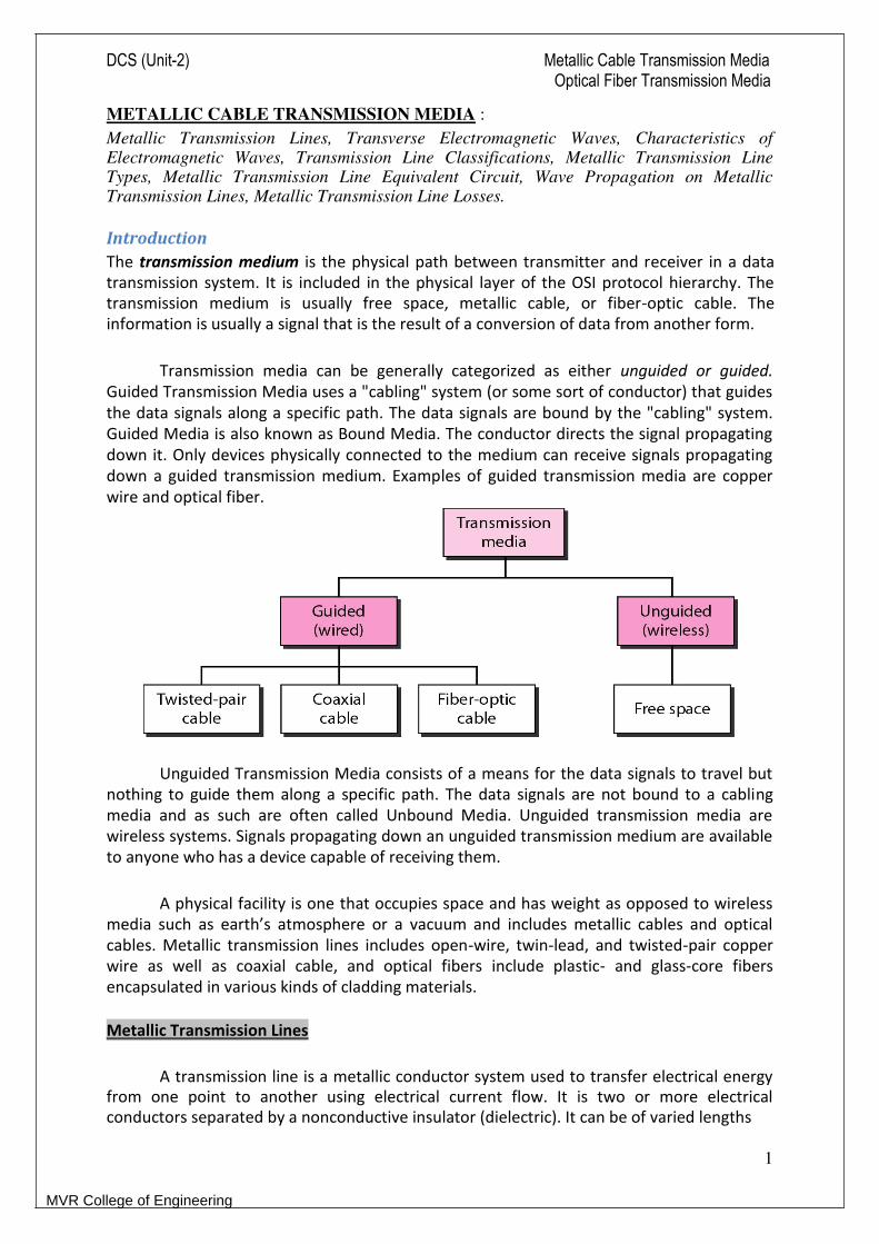
Transmission media can be generally categorized as either unguided or guided.
Guided Transmission Media uses a "cabling" system (or some sort of conductor) that guides
the data signals along a specific path. The data signals are bound by the "cabling" system.
Guided Media is also known as Bound Media. The conductor directs the signal propagating
down it. Only devices physically connected to the medium can receive signals propagating
down a guided transmission medium. Examples of guided transmission media are copper
wire and optical fiber.
Unguided Transmission Media consists of a means for the data signals to travel but
nothing to guide them along a specific path. The data signals are not bound to a cabling
media and as such are often called Unbound Media. Unguided transmission media are
wireless systems. Signals propagating down an unguided transmission medium are available
to anyone who has a device capable of receiving them.
A physical facility is one that occupies space and has weight as opposed to wireless
edia su h as ea th’s at osphe e o a a uu a d i ludes etalli a les a d opti al cables. Metallic transmission lines includes open-wire, twin-lead, and twisted-pair copper
wire as well as coaxial cable, and optical fibers include plastic- and glass-core fibers
encapsulated in various kinds of cladding materials.
Metallic Transmission Lines
A transmission line is a metallic conductor system used to transfer electrical energy
from one point to another using electrical current flow. It is two or more electrical
conductors separated by a nonconductive insulator (dielectric). It can be of varied lengths
1
MVR College of Engineering
DCS (Unit-2) Metallic Cable Transmission Media
Optical Fiber Transmission Media
varying from few inches to several thousand miles. It can be used to propagate dc or low-frequency ac and also very high frequencies such as microwave radio-frequency signals.
Transverse Electromagnetic Waves
The two basic kinds of waves are longitudinal and transverse. With longitudinal
waves, the displacement is in the direction of propagation. A surface wave or sound waves
can be said as examples of longitudinal waves. With transverse waves, the direction or
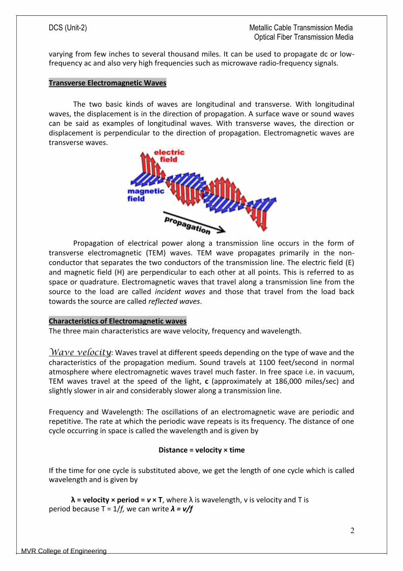
displacement is perpendicular to the direction of propagation. Electromagnetic waves are
transverse waves.
Propagation of electrical power along a transmission line occurs in the form of
transverse electromagnetic (TEM) waves. TEM wave propagates primarily in the non-
conductor that separates the two conductors of the transmission line. The electric field (E)
and magnetic field (H) are perpendicular to each other at all points. This is referred to as
space or quadrature. Electromagnetic waves that travel along a transmission line from the
source to the load are called incident waves and those that travel from the load back
towards the source are called reflected waves.
Characteristics of Electromagnetic waves
The three main characteristics are wave velocity, frequency and wavelength.
Wave velocity: Waves travel at different speeds depending on the type of wave and the characteristics of the propagation medium. Sound travels at 1100 feet/second in normal
atmosphere where electromagnetic waves travel much faster. In free space i.e. in vacuum,
TEM waves travel at the speed of the light, c (approximately at 186,000 miles/sec) and
slightly slower in air and considerably slower along a transmission line.
Frequency and Wavelength: The oscillations of an electromagnetic wave are periodic and
repetitive. The rate at which the periodic wave repeats is its frequency. The distance of one
cycle occurring in space is called the wavelength and is given by
Distance = velocity × time
If the time for one cycle is substituted above, we get the length of one cycle which is called wavelength and is given by
λ = velocity × period = v × T, where λ is a ele gth, is elo it a d T is period because T = 1/f, we can write λ = v/f
2
MVR College of Engineering
DCS (Unit-2) Metallic Cable Transmission Media
Optical Fiber Transmission Media
As fo f ee spa e p opagatio , = ; the le gth of o e le is λ = /f = × 8 m/s/f cycles/s
Transmission line classifications
Balanced Transmission Line
In two wire balanced lines, both conductors carry current. One conductor carries the signal
and the other conductor in the return path. This type of transmission is called differential or
balanced signal transmission. Both conductors in a balanced line carry signal currents, which
are equal in magnitude with respect to electrical ground but travel in opposite directions.
Currents that flow in opposite directions in a balanced wire pair are called metallic circuit
currents and currents that flow in same direction are called longitudinal currents. The chief
advantage of the balanced line format is good rejection of external noise. Common forms of
balanced line are twin-lead, used for radio frequency signals and twisted pair, used for
lower frequencies.
Unbalanced Transmission Line
With an unbalanced transmission line, one wire is at ground potential, whereas the other
wire is at signal potential. This type of transmission line is called single-ended or unbalanced
signal transmission. The ground wire may also be the reference for other signal-carrying
wires and must go anywhere any of the signal wires go.
Unbalanced transmission lines have the advantage of requiring only one wire for each signal
and only one ground line is required no matter how many signals are grouped into one
conductor. Balanced transmission lines can be connected to unbalanced transmission lines
and vice versa with special transformers called balums.
Metallic Transmission Line Types
All data communications systems and computer networks are interconnected to some
degree with cables, which form the most important part of the transmission medium
transporting signals between computers.
Parallel-Conductor Transmission Lines
Parallel-wire transmission lines are comprised of two or more metallic conductors separated
by a nonconductive insulating material called a dielectric. Common dielectric materials
include air, rubber, polyethylene, paper, mica, glass and Teflon. The most common parallel-
conductor transmission lines are open-wire, twin lead and twisted pair, including unshielded
twisted pair (UTP) and shielded twisted pair (STP).
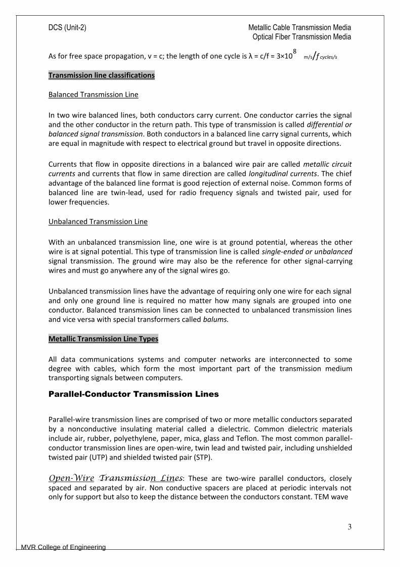
Open-Wire Transmission Lines: These are two-wire parallel conductors, closely spaced and separated by air. Non conductive spacers are placed at periodic intervals not only for support but also to keep the distance between the conductors constant. TEM wave
3
MVR College of Engineering
DCS (Unit-2) Metallic Cable Transmission Media
Optical Fiber Transmission Media
propagates in the air between the conductors, which acts as dielectric. The main advantage is its simple construction.
Since no shielding is present, the radiation losses are high and cable is susceptible to picking
up signals through mutual induction, which produces crosstalk. The primary usage is in
standard voice-grade telephone applications.
Twin lead: Twin-lead is essentially the same as open-wire transmission line except that the spacers between the two conductors are replaced with a continuous solid dielectric
ensuring the uniform spacing along the entire cable.
It is mainly used to connect televisions to rooftop antennas. Common dielectric materials used with twin-lead cable are Teflon and polyethylene.
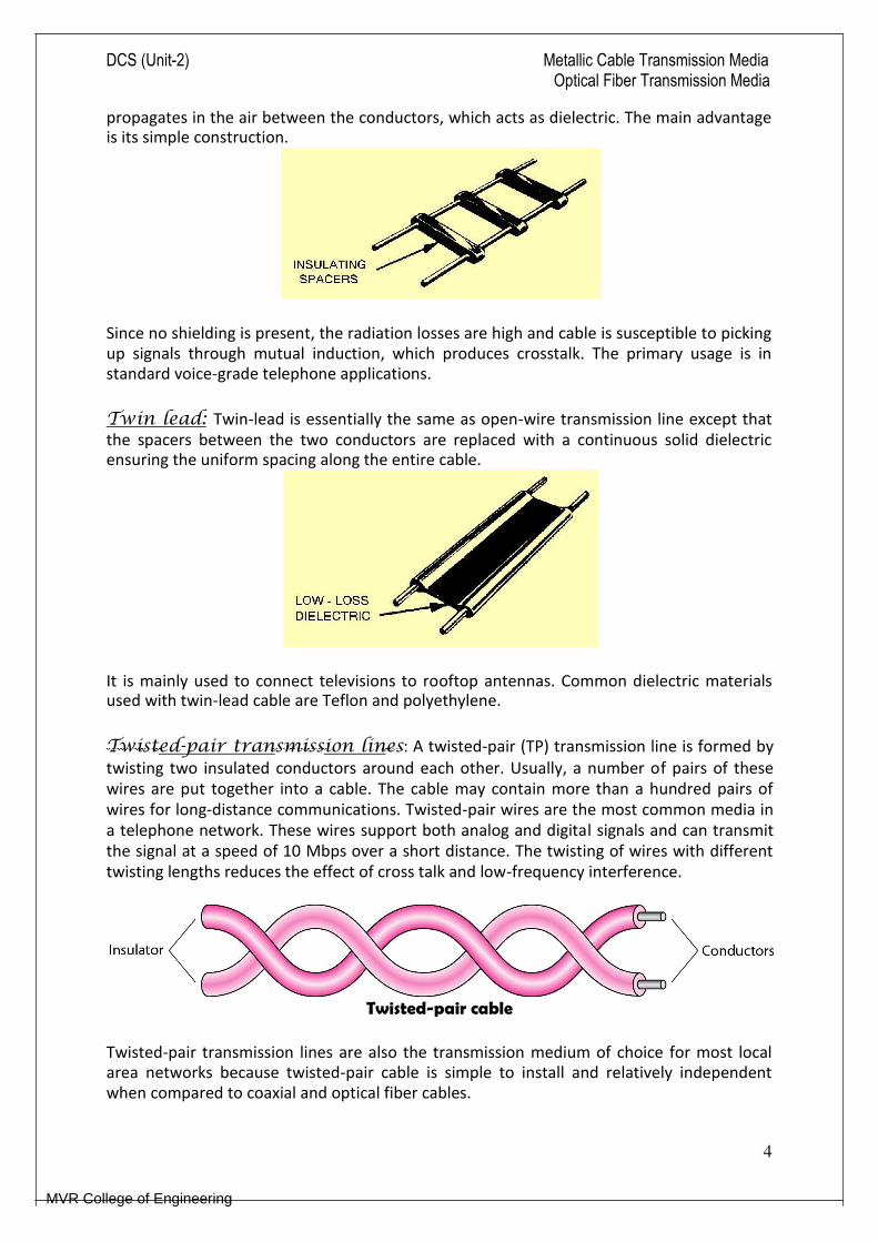
Twisted-pair transmission lines: A twisted-pair (TP) transmission line is formed by twisting two insulated conductors around each other. Usually, a number of pairs of these
wires are put together into a cable. The cable may contain more than a hundred pairs of
wires for long-distance communications. Twisted-pair wires are the most common media in
a telephone network. These wires support both analog and digital signals and can transmit
the signal at a speed of 10 Mbps over a short distance. The twisting of wires with different
twisting lengths reduces the effect of cross talk and low-frequency interference.
Twisted-pair cable
Twisted-pair transmission lines are also the transmission medium of choice for most local
area networks because twisted-pair cable is simple to install and relatively independent
when compared to coaxial and optical fiber cables.
4
MVR College of Engineering

DCS (Unit-2) Metallic Cable Transmission Media
Optical Fiber Transmission Media
The two basic types of twisted-pair transmission lines specified are unshielded twisted pair (UTP) and shielded twisted pair (STP).
Unshielded twisted-pair: An UTP cable consists of two copper wires where each wire is
seperately encapsulated in PVC (polyvinyl chloride) insulation. Bandwidth can be improved
by controlling the number of twists per foot and also the manner in which multiple pairs are
twisted around each other. The minimum number of twists for UTP cable is two per foot.
UTPs are cheaper, more flexible, and easier to install. They provide enough support for
telephone systems and are not covered by metal insulation. They offer acceptable
performance for a long-distance signal transmission, but as they are uninsulated, they are
affected by cross talk, atmospheric conditions, electromagnetic interference, and adjacent
twisted pairs, as well as by any noise generated nearby. The majority of the telephone
twisted pairs are unshielded and can transmit signals at a speed of 10 Mbps.
The Electronic Industries Association (EIA) has developed standard to grade UTP cable by quality; Category 1 as the lowest quality and category 6 as the highest quality.
1. Category 1: The basic twisted-pair cabling used in telephone systems. This level of quality is fine for voice but inadequate for data transmission.
2. Category 2: This category is suitable for voice and data transmission of up to 2Mbps.
3. Category 3: This category is suitable for data transmission of up to 10 Mbps. It is now the standard cable for most telephone systems. At least three twist per feet
4. Category 4: This category is suitable for data transmission of up to 20 Mbps. 5. Category 5: This category is suitable for data transmission of up to 100 Mbps.
6. Category 6: CAT- 6 is recently proposed cable type comprised of four pairs of wire
capable of operating at transmission rates of up to 400Mbps.
Advantages of UTP are its easy to terminate, installation costs are less and more lines can be
run through the same wiring ducts. Disadvantages of UTP are its a bit noisy and prone to
interference.
5
MVR College of Engineering
DCS (Unit-2) Metallic Cable Transmission Media
Optical Fiber Transmission Media
Categories of unshielded twisted-pair cables
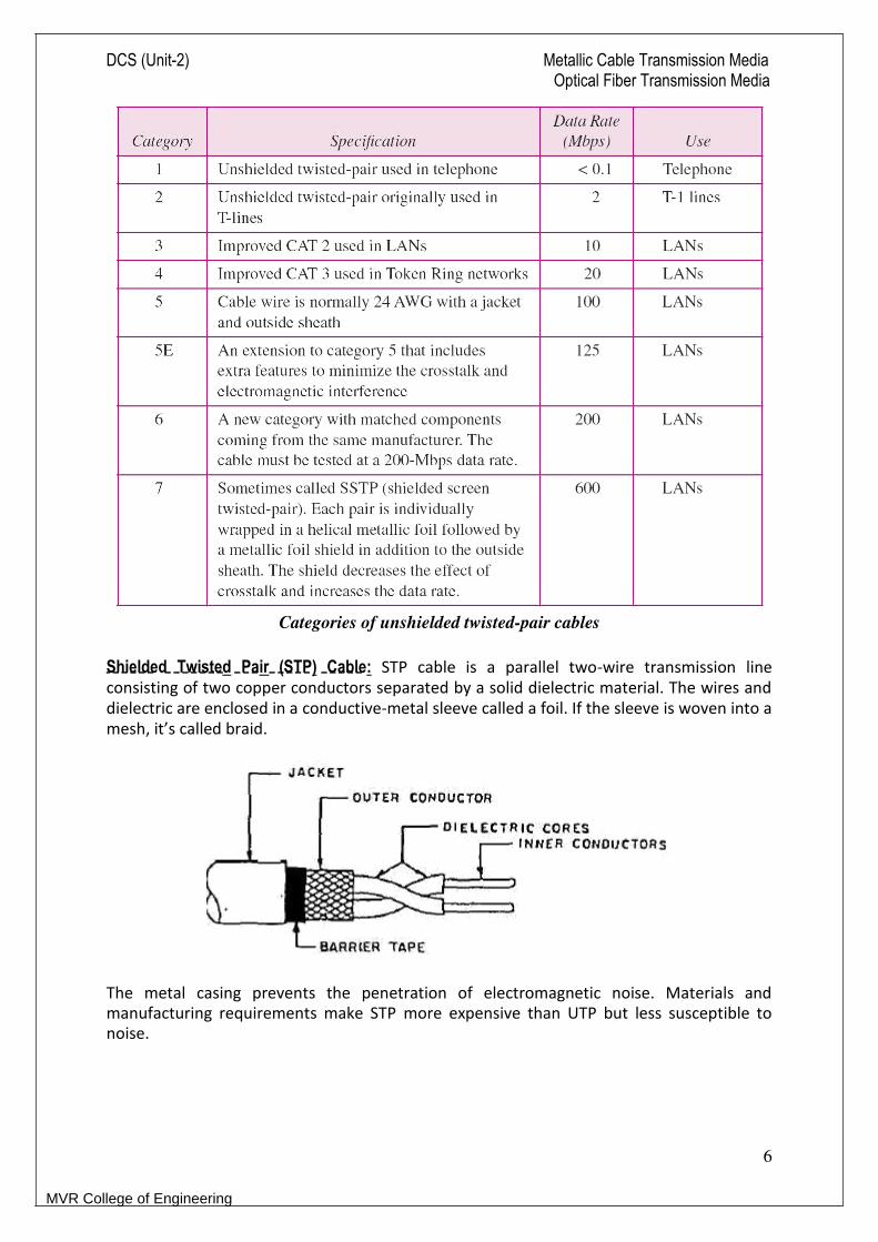
Shielded Twisted Pair (STP) Cable: STP cable is a parallel two-wire transmission line consisting of two copper conductors separated by a solid dielectric material. The wires and
dielectric are enclosed in a conductive-metal sleeve called a foil. If the sleeve is woven into a
esh, it’s alled aid.
The metal casing prevents the penetration of electromagnetic noise. Materials and
manufacturing requirements make STP more expensive than UTP but less susceptible to
noise.
6
MVR College of Engineering

DCS (Unit-2) Metallic Cable Transmission Media
Optical Fiber Transmission Media
Plenum Cable: Plenum cables are the electrical or telecommunication cables (or wires) which are installed in environmental air spaces in the interior of many commercial and
residential buildings. It is common practice to route communication cables and the like for
computers, data devices, and alarm systems through plenums in building constructions. If a
fire occurs in a building which includes plenums or risers, the non-fire retardant plenum
construction would enable the fire to spread very rapidly throughout the entire building.
Typically plenum data cables have two or more pairs of insulated conductors in a common
jacket. The insulation can be made of several types of flame retardant insulation. A plenum
is defined as a compartment or chamber to which one or more air ducts are connected and
which forms part of the air distribution system of the structure. Plenum cables have a
plurality of twisted pair conductors surrounded by a jacket. The twisted pairs generally all
have the same twist or substantially the same twist. A typical and widely used flame
retardant insulation for conductors in data plenum cables is fluorinated ethylene-propylene.
Category 5 plenum cable made of jacketed twisted pairs of insulated conductors has to
satisfy a number of electrical requirements set by the EIA/TIA specification 568A.
Coaxial (Concentric) Transmission Lines
Because of the advent of modern UTP and STP twisted pair cables, coaxial cable is seen very
less in computer networks, but still has very high importance in analog systems, such as
cable television distribution networks. The basic coaxial cable consists of a center conductor
surrounded by a dielectric material (insulation), then a concentric (uniform distance from
the center) shielding, and finally a rubber environmental protection outer jacket. A coaxial
cable with one layer of foil insulation and one layer of braided shielding is referred to as
dual shielded and if two layers of foil insulation and two layers of braided metal shielding
a e p ese t, it’s alled quad shielding.
Two basic types of coaxial cables are present: rigid air filled and solid flexible. Rigid
air-filled cables are relatively expensive and are tough to maintain. Coaxial cables are
capable of operating at higher bit rates than their parallel-wire counterparts, very secure
than twisted-pair cable, can be used over long distances, immune to external radiation and
radiate little themselves. Disadvantages of coaxial transmission lines are their poor cost-to-
performance ratio, low reliability, and high maintenance.
7
MVR College of Engineering
DCS (Unit-2) Metallic Cable Transmission Media
Optical Fiber Transmission Media
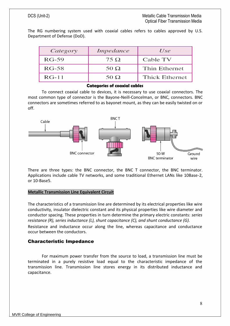
The RG numbering system used with coaxial cables refers to cables approved by U.S. Department of Defense (DoD).
Categories of coaxial cables
To connect coaxial cable to devices, it is necessary to use coaxial connectors. The
most common type of connector is the Bayone-Neill-Concelman, or BNC, connectors. BNC
connectors are sometimes referred to as bayonet mount, as they can be easily twisted on or
off.
There are three types: the BNC connector, the BNC T connector, the BNC terminator.
Applications include cable TV networks, and some traditional Ethernet LANs like 10Base-2,
or 10-Base5.
Metallic Transmission Line Equivalent Circuit
The characteristics of a transmission line are determined by its electrical properties like wire
conductivity, insulator dielectric constant and its physical properties like wire diameter and
conductor spacing. These properties in turn determine the primary electric constants: series
resistance (R), series inductance (L), shunt capacitance (C), and shunt conductance (G).
Resistance and inductance occur along the line, whereas capacitance and conductance occur between the conductors.
Characteristic Impedance
For maximum power transfer from the source to load, a transmission line must be
terminated in a purely resistive load equal to the characteristic impedance of the
transmission line. Transmission line stores energy in its distributed inductance and
capacitance.
8
MVR College of Engineering

DCS (Unit-2) Metallic Cable Transmission Media
Optical Fiber Transmission Media
Usi g Oh ’s la , the ha a te isti i peda e is si pl the atio of the sou e oltage Eo)
to the line current (Io), given by
Zo = Eo/ Io , where Zo is characteristic impedance in ohms, Eo is source voltage in
volts and Io is transmission line current in amps.
Characteristic impedance of a two wire parallel transmission line with an air dielectric can be
determined from its physical dimensions Zo = 276 log D/r where D is distance between the centres of the two conductors and R is radius of the conductors.
Characteristic impedance of a coaxial cable can also be determined from its physical
dimensions: where, D is inside diameter of the conductor and Ɛr is
relative dielectric constant of the insulating material.
Wave Propagation on Metallic Transmission Lines
EM waves travel at the speed of light through vacuum and nearly the same through air, but
they travel considerably slowly in metallic transmission lines, where the conductor is
generally copper and the dielectric materials vary with cable type.
Velocity Factor and Dielectric Constant
Velocity factor is defined as the ratio of the actual velocity of propagation of an
electromagnetic wave through a given medium to the velocity of propagation through a
vacuum. Mathematically, given as:
Vf = Vp / c, where Vf is velocity factor, Vp is actual velocity of propagation and c is velocity
of propagation through a vacuum (3×10⁸ m/s).
Dielectric constant is simply the relative permittivity of a material. The dielectric constant
depends on the type of insulating material used. The velocity at which an EM wave
propagates along a transmission line varies with the inductance and capacitance of the
cable. Time can be given as: T = √LC. Inductance, capacitance ad velocity of propagation can
be given by the formula, velocity × Time = Distance
Therefore, Vp = Distance/ Time = D/T which can be written as Vp = D/ √LC
If the distance is normalized to 1 meter, the velocity of propagation for a lossless
transmission line is Vp = 1 / √LC
Metallic Transmission Line Losses
Signal power is lost in a transmission line through different ways: conductor loss, radiation
loss, dielectric heating loss, coupling loss and corona. All these losses are lumped together
and are specified as attenuation loss in decibels per unit length.
9
MVR College of Engineering

DCS (Unit-2) Metallic Cable Transmission Media
Optical Fiber Transmission Media
Conductor Losses: As electrical current flows through a metallic transmission line, there is an inherent and unavoidable power loss because of the finite resistance present in the
line. This loss is termed as conductor loss or conductor heating loss and is simply I2r power
loss.
Radiation Losses: Radiation and Induction losses are similar in that both are caused by the fields surrounding the conductors. Induction losses occur when the electromagnetic
field about a conductor cuts through any nearby metallic object and a current is induced in
that object. Radiation losses are reduced by properly shielding the cable. Therefore, STP and
coaxial cables have less radiation than UTP, twin lead and openwire.
Coupling Losses: Coupling loss occurs whenever a connection is made to or from a transmission line or when two sections of transmission line are connected together.
Discontinuities are the locations where dissimilar materials meet and they tend to heat up,
radiate energy, and dissipate power.
Corona: Corona is a luminous discharge that occurs between the two conductors of a transmission line, when the difference of potential between them exceeds the breakdown voltage of the dielectric insulator. When corona occurs, the transmission line is destroyed.
10
MVR College of Engineering

DCS (Unit-2) Metallic Cable Transmission Media
Optical Fiber Transmission Media
OPTICAL FIBER TRANSMISSION MEDIA :
Advantages of Optical Fiber Cables, Disadvantages of Optical Fiber Cables, Electromagnetic spectrum, Optical Fiber Communications System Block Diagram, Optical Fiber construction, The Physics of Light, Velocity of Propagation, Propagation of Light Through an Optical fiber Cable, Optical Fiber Modes and Classifications, Optical Fiber Comparison, Losses in Optical Fiber Cables, Light sources, Light Detectors, Lasers.
An optical communications system is one that uses light as the carrier of information. They
use glass or plastic fiber cables to contain the light waves and guide them in a manner
similar to the way EM waves are guided through a metallic transmission media.
Advantages of Optical Fiber Cables
Wider bandwidth and greater information capacity: The light wave occupies the frequency range
between 2×10¹²
Hz to 37×1012
Hz. This makes the information carrying capability of fiber optic cables is much higher.
Immunity to crosstalk: Since fiber optic cables use glass and plastic fibers, which are non-conductors of electrical current, no magnetic field is present. No magnetic induction means no crosstalk.
Immunity to static interference: As optical fiber cables are non-conductors, they are immune
to electromagnetic interference (EMI) caused by lightning, electric motors, relays, fluorescent lights and other electrical noise sources.
Environmental immunity: Optical fibers are more immune to environmental extremes. They
can operate over large temperature variations and are also not affected by corrosive liquids and gases.
Safety and convenience: As only glass and plastic fibers are present, no electrical currents or
voltages are associated with them. Also they can be used around any volatile liquids and gasses without worrying about their causing explosions or fires.
Lower transmission loss: Fiber optic cables offers less signal attenuation over long distances.
Typically, it is less than 1 dB/km
Security: Optical fibers are more secure as they are almost impossible to tap into because they do not radiate signals. No ground loops exist between optical fibers hence they are more secure.
Durability and reliability: Optical cables last longer and are more reliable than metallic
facilities because fiber cables have a higher tolerance to changes in environmental conditions and are immune to corrosive materials.
Economics: Cost of optical fiber cables is same as metallic cables. Fiber cables have less loss
and require fewer repeaters, which in turn needs lower installation and overall system costs.
Disadvantages of Optical Fiber Cables
Interfacing costs: As optical cables need to be connected standard electronic facilities requiring expensive interfaces
Strength: Optical cables have lower tensile strength than coaxial cable. They need an extra coating of Kevlar and also a protective jacket of PVC. Glass fiber is also fragile making them less attractive in case of hardware portability is required
11
MVR College of Engineering
DCS (Unit-2) Metallic Cable Transmission Media
Optical Fiber Transmission Media
Remote electrical power: Occasionally, electrical power needs to be provided to remote interfaces,
which cannot be accomplished using optical cables
Losses through bending: Bending the cable causes irregularities in the cable dimensions, resulting in loss of signal power. Also, optical cables are prone to manufacture defects causing an excessive loss of signal power.
Specialized tools, equipment and training: Special tools are required to splice and repair
cables and special test equipment are needed to make routine measurements. Technicians working on optical cables need special skills and training.
Electromagnetic Spectrum
The electromagnetic spectrum is the range of all possible frequencies of electromagnetic radiation. The "electromagnetic spectrum" of an object is the characteristic distribution of electromagnetic radiation emitted or absorbed by that particular object. The frequency
spectrum extends from the subsonic frequencies (a few hertz) to cosmic rays (1023
Hz). The
light frequency spectrum can be divided into three general bands.
1. Infrared: The band of frequencies that is too high to be seen by the human eye with
wavelengths ranging between 770nm and 106 nm. Optical fibers generally operate in
infrared band. 2. Visible: The band of light frequencies to which the human eye will respond with
wave lengths ranging between 390nm and 770nm. This band is visible to human eye. 3. Ultraviolet: The band of light frequencies, that are too low to be seen by the human
eye with wave lengths ranging between 10nm and 390nm.
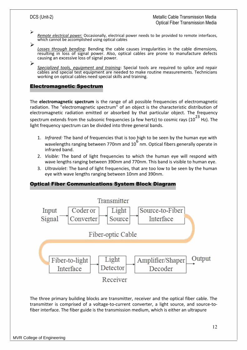
Optical Fiber Communications System Block Diagram
The three primary building blocks are transmitter, receiver and the optical fiber cable. The
transmitter is comprised of a voltage-to-current converter, a light source, and source-to-
fiber interface. The fiber guide is the transmission medium, which is either an ultrapure
12
MVR College of Engineering
DCS (Unit-2) Metallic Cable Transmission Media
Optical Fiber Transmission Media
glass or a plastic cable. The receiver includes a fiber-to-interface, a photodetector, and a current-to-voltage converter.
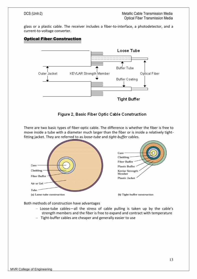
Optical Fiber Construction
There are two basic types of fiber-optic cable. The difference is whether the fiber is free to
move inside a tube with a diameter much larger than the fiber or is inside a relatively tight-
fitting jacket. They are referred to as loose-tube and tight-buffer cables.
Both methods of construction have advantages
– Loose-tube cables—all the st ess of a le pulli g is take up the a le’s
strength members and the fiber is free to expand and contract with temperature
– Tight-buffer cables are cheaper and generally easier to use
13
MVR College of Engineering

DCS (Unit-2) Metallic Cable Transmission Media
Optical Fiber Transmission Media
Physics of Light
Albert Einstein and Max Planck showed that when light is emitted or absorbed, it behaves
like an electromagnetic wave and also like a particle called a photon, which possesses
e e g p opo tio al to its f e ue . This is k o as Pla k’s La . It states that he visible light or high-frequency electromagnetic radiation illuminates a metallic surface,
electrons are emitted . It is e p essed athe ati all as:
Ep = hf,
where Ep is e e g of the photo s i joules, h is Pla k’s o sta t a d f is f e ue of light
The process of decaying from one energy level to another energy level is called
spontaneous decay or spontaneous emission. The process of moving from one energy level
to another is called absorption.
Optical power measures the rate at which electromagnetic waves transfer light energy. It is
described as the flow of light energy past a given point in a specified time. Expressed
mathematically as:
P = d(energy)/ d(time) = dQ/ dt , where P is optical power in watts and dQ is instantaneous charge in joules
Velocity of Propagation
Refraction: Refraction is the bending of light when the light passes from one medium to another. The angle between the light ray and the normal as it leaves a medium is called the
angle of incidence. The angle between the light ray and the normal as it enters a medium is
called the angle of refraction.
When an electromagnetic wave is reduced as it passes from one medium to another
medium of denser material, the light ray changes direction or refracts (bends) toward the
normal. When an electromagnetic wave passes from a more dense material into a less
dense material, the light ray is refracted away from the normal. The normal is simply an
imaginary line drawn perpendicular to the interface of the two materials at the point of
incidence
14
MVR College of Engineering

DCS (Unit-2) Metallic Cable Transmission Media
Optical Fiber Transmission Media
Refractive Index: Refractive index is simply the ratio of the velocity of propagation of light ray in free space to the velocity of propagation of a light ray in a given material. Given by,
n = c/v, where n is refractive index and c is speed of light (m/sec) and v is speed of light in a given material (m/sec). Typical indexes of refraction of some materials are given below:
Snell’s Law: This relationship between the angles of incidence and refraction and the indices of refraction of the two medium is known as Snell's Law. Snell's law applies to the
refraction of light in any situation, regardless of what the two media are.
Refractive model for Snell’s Law
S ell’s La is stated athe ati all as:
n1 sinθ1 = n2 sinθ2
15
MVR College of Engineering
DCS (Unit-2) Metallic Cable Transmission Media
Optical Fiber Transmission Media
Where, n1 is refractive index of material 1, n2 is ef a ti e i de of ate ial , θ1 is angle of
i ide e a d θ2 is angle of refraction.
Critical Angle: The a gle of i ide e is alled the iti al a gle θc), which is defined as the minimum angle of incidence at which a light ray may strike the interface of two media and result in an angle of refraction of 90 degrees or greater. Light ray has to travel from medium of higher refractive index to that of lower refractive index. Expressed as:
θc = sin-1
n2/n1
Acceptance angle, acceptance cone and numerical aperture: For a ray of light to propagate down the cable, it must strike the internal core/cladding interface at an angle that is greater than the critical angle.
θin(max) = sin -1
√(n12 – n2
2)
Where, θin(max) is acceptance angle or acceptance cone half angle. It defines the maximum angle in which external light rays may strike the air/glass interface and still propagate down the fiber.
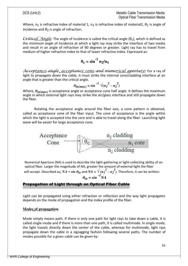
Rotating the acceptance angle around the fiber axis, a cone pattern is obtained,
called as acceptance cone of the fiber input. The cone of acceptance is the angle within
which the light is accepted into the core and is able to travel along the fiber. Launching light
wave will be easier for large acceptance cone.
Numerical Aperture (NA) is used to describe the light-gathering or light-collecting ability of an
optical fiber. Larger the magnitude of NA, greater the amount of external light the fiber
will accept. Described as, NA = sin θin and NA = √ (n12 – n2
2). Therefore, it can be written:
θin = sin -1
NA
Propagation of Light through an Optical Fiber Cable
Light can be propagated using either refraction or reflection and the way light propagates depends on the mode of propagation and the index profile of the fiber.
Modes of propagation
Mode simply means path. If there is only one path for light rays to take down a cable, it is
called single mode and if there is more than one path, it is called multimode. In single mode,
the light travels directly down the center of the cable, whereas for multimode, light rays
propagate down the cable in a zigzagging fashion following several paths. The number of
modes possible for a given cable can be given by:
16
MVR College of Engineering
DCS (Unit-2) Metallic Cable Transmission Media
Optical Fiber Transmission Media
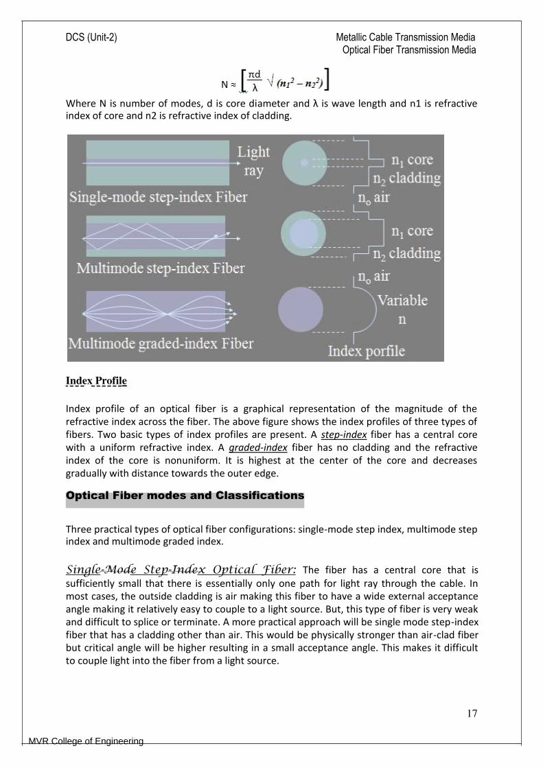
Where N is number of modes, d is core dia ete a d λ is a e le gth a d is ef a ti e index of core and n2 is refractive index of cladding.
Index Profile
Index profile of an optical fiber is a graphical representation of the magnitude of the
refractive index across the fiber. The above figure shows the index profiles of three types of
fibers. Two basic types of index profiles are present. A step-index fiber has a central core
with a uniform refractive index. A graded-index fiber has no cladding and the refractive
index of the core is nonuniform. It is highest at the center of the core and decreases
gradually with distance towards the outer edge.
Optical Fiber modes and Classifications
Three practical types of optical fiber configurations: single-mode step index, multimode step index and multimode graded index.
Single-Mode Step-Index Optical Fiber: The fiber has a central core that is sufficiently small that there is essentially only one path for light ray through the cable. In
most cases, the outside cladding is air making this fiber to have a wide external acceptance
angle making it relatively easy to couple to a light source. But, this type of fiber is very weak
and difficult to splice or terminate. A more practical approach will be single mode step-index
fiber that has a cladding other than air. This would be physically stronger than air-clad fiber
but critical angle will be higher resulting in a small acceptance angle. This makes it difficult
to couple light into the fiber from a light source.
17
MVR College of Engineering
DCS (Unit-2) Metallic Cable Transmission Media
Optical Fiber Transmission Media
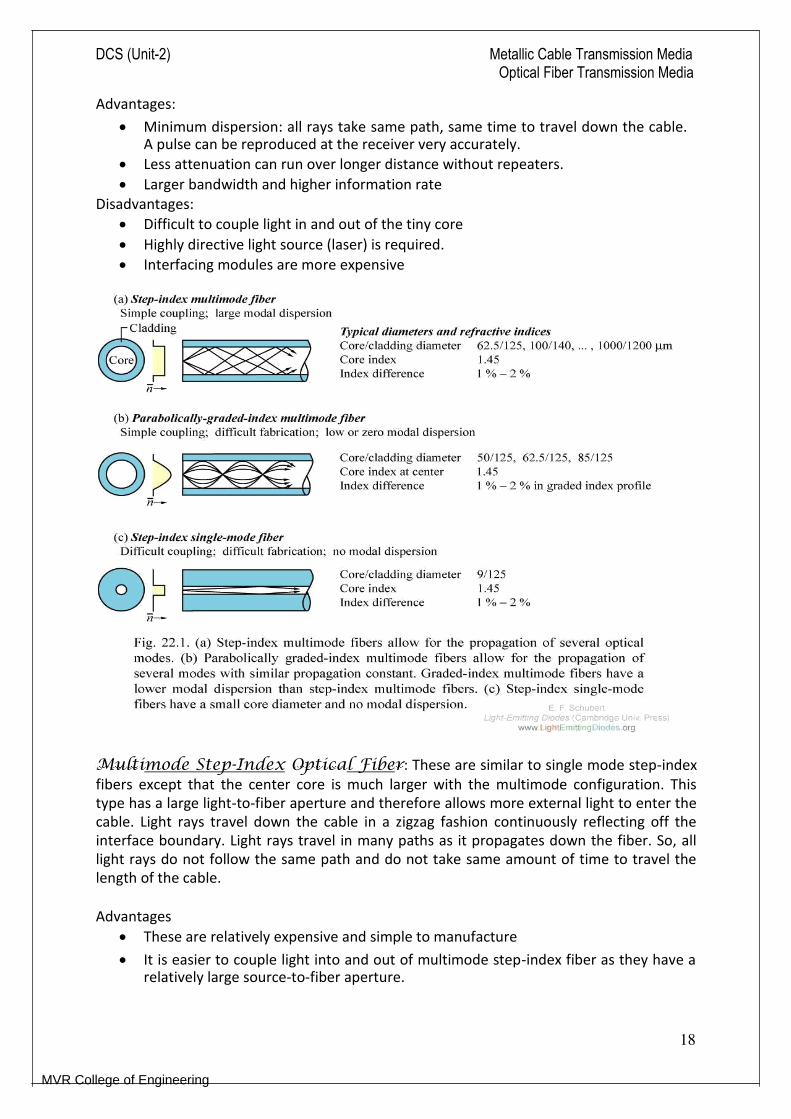
Advantages:
Minimum dispersion: all rays take same path, same time to travel down the cable. A pulse can be reproduced at the receiver very accurately.
Less attenuation can run over longer distance without repeaters. Larger bandwidth and higher information rate
Disadvantages:
Difficult to couple light in and out of the tiny core Highly directive light source (laser) is required. Interfacing modules are more expensive
Multimode Step-Index Optical Fiber: These are similar to single mode step-index fibers except that the center core is much larger with the multimode configuration. This
type has a large light-to-fiber aperture and therefore allows more external light to enter the
cable. Light rays travel down the cable in a zigzag fashion continuously reflecting off the
interface boundary. Light rays travel in many paths as it propagates down the fiber. So, all
light rays do not follow the same path and do not take same amount of time to travel the
length of the cable.
Advantages
These are relatively expensive and simple to manufacture It is easier to couple light into and out of multimode step-index fiber as they have a
relatively large source-to-fiber aperture.
18
MVR College of Engineering

DCS (Unit-2) Metallic Cable Transmission Media
Optical Fiber Transmission Media
Disadvantages
As light rays travel in different paths, large difference in propagation times results.
So, the rays travelling down have a tendency to spread out. Consequently the pulse
of light propagating down is more distorted than other types of fibers. Less bandwidths and lower rate of information transfer rates when compared to
other types.
Multimode Graded-Index Optical Fiber: These fibers are characterized by a central core with a nonuniform refractive index. Cables density is maximum at centre and
decreases gradually towards the edge. Light ray is propagated through refraction. As the
light propagates across the core toward the center it intersects a less dense to more dense
medium. Consequently, light rays constantly being refracted resulting in continuous bending
of light rays. The light rays take approximately the same amount of time to travel the length
of the fiber. This cable is mostly used for long distance communication.
Losses in Optical Fiber Cables
Power loss in optical fiber cables is often called attenuation and results in reduction of power of light wave as it travels down the cable. Generally, total power loss is expressed as:
A(dB) = 10 log (Pout / Pin) where A(dB) is total reduction in power level, attenuation and
Pout is cable output power and Pin is cable input power. Multimode fibers tend to have
more attenuation than single-mode cables because of increased scattering of light wave.
Transmission losses in optical fibers result in reduction in light power, thus reducing the
system bandwidth, information transmission rate, efficiency, and overall system capacity.
The predominant losses are:
Absorption Losses: It is analogous to power dissipation in copper cables as impurities in the fiber absorb the light and convert it to heat. Three main factors contribute to absorption losses.
Ultraviolet absorption:- Caused by valence electrons in the silica material from which fibers are manufactured.
Infrared absorption: - Result of photons of light that are absorbed by the atoms of the glass core molecules.
Ion resonance absorption: - Caused by OH- ion in the material. Iron, copper and chromium molecules also cause ion absorption
Material or Rayleigh Scattering Losses: Rayleigh scattering of light is due to small localized changes in the refractive index of the core and cladding material. Two main causes for this:
The first is due to slight fluctuation in mixing of ingredients. The random changes because of this are impossible to eliminate completely.
The other cause is slight change in density as the silica cools and solidifies. When light ray strikes such zones, it gets scattered in all directions. The amount of scatter
19
MVR College of Engineering

DCS (Unit-2) Metallic Cable Transmission Media
Optical Fiber Transmission Media
depends on the size of the discontinuity compared with the wavelength of the light. So the shortest wavelength suffers most scattering.
Chromatic Distortion or Wavelength Dispersion: Light rays that are simultaneously emitted from an LED and propagated down an optical fiber do not arrive at
the far end of the fiber at the same time, which results in an impairment called chromatic
distortion. It occurs in only in fibers with a single mode of transmission and can be
eliminated using monochromatic light sources like injection laser diode (ILD).
Radiation Losses: These are caused predominantly by small bends wand kinks in the fiber. The two types of bends are: microbends and constant-radius bends. Microbending
occurs as result of differences in the thermal contraction rates between core and cladding
material and results in a material bend along the axis of the fiber and represents a
discontinuity where Rayleigh scattering occurs. Constant-radius bends are caused by
excessive pressure and tension and generally occur when fibers are bent during installation.
Modal dispersion: Modal dispersion (called pulse spreading) is caused by the difference in the propagation times of light rays that take different paths down a fiber and occurs only
in multimode fibers. It can be reduced considerably by using graded index fibers and almost
entirely eliminated using single-mode step-index fibers. If three rays of light are emitted into
the fiber at the same time, each ray would reach the far end at a different time resulting in a
spreading out of light energy with respect to time. This is called modal dispersion.
Coupling Losses: -These losses are caused by imperfect physical connections. These occur at three types of junctions: light source-to-fiber connections, fiber-to-fiber
connections, and fiber-to-photodetector connections. They are caused by one of the
following alignment problems:
20
MVR College of Engineering

DCS (Unit-2) Metallic Cable Transmission Media
Optical Fiber Transmission Media
Lateral displacement: It is the lateral or axial displacement between two pieces of adjoining fiber
cables.
Gap displacement (misalignment): When splices are made in optical fibers, the fibers should actually touch. The farther apart the fibers are, the greater the loss of light.
Angular displacement: It is sometimes called angular displacement and if it is less than 2 degrees, the
loss will typically be less than 0.5 dB.
Imperfect surface finish: The ends of two adjoining fibers should be highly polished and fit together squarely. If the fiber ends are less than 3 degrees off from perpendicular, the losses will typically be less than 0.5 dB.
Light Sources
Light sources are used in fiber optic communication to generate light pulses at
wavelengths efficiently propagated by the optical fiber. They also should produce sufficient
power to allow the light to propagate through the fiber without causing distortion in the
cable or receiver. Two types of practical light sources used to generate light for optical fiber
communications systems: light-e itti g diodes LED’s a d i je tio lase diodes ILD’s .
Light Emitting Diodes: A LED is a p-n junction diode, usually made from a semiconductor material such as aluminum-gallium-arsenide (AlGaAs) or gallium-arsenide-
phosphide GaAsP . LED’s e it light spo ta eous e issio -light is emitted as a result of
the recombination of electrons and holes. LEDs can provide light output when forward
biased. The LED has a low output power, slower switching speed and greater spectral width,
hence more dispersion. These deficiencies make it not useful for high speed and long
distance communication. The output of LED is non-coherent and coupling efficiency is very
low.
Injection Laser Diode: ILD’s a e si ila to LED’s a d the a t si ila l elo a e tai threshold current. Above the threshold current, and ILD oscillates and lasing occurs. As
current passes through a forward biased p-n junction diode, light is emitted by spontaneous
emission at a frequency determined by the energy gap of the semiconductor material. The
21
MVR College of Engineering
DCS (Unit-2) Metallic Cable Transmission Media
Optical Fiber Transmission Media
radiant output power of ILD is more directive than LED. After lasing occurs, the optical power increases dramatically, with small increases in drive current.
Advantages
1. ILD’s e it ohe e t o de l light o pared to incoherent (disorderly) light emitted
by LED. So ILD have a more direct radian pattern, making it easier to couple light
emitted by the ILD into an optical fiber cable. Coupling losses are reduced and also
small fibers can be used. 2. The radiant output power of ILD is greater than that for an LED. Typically the output
po e fo a ILD is 5 W a d o l .5 W fo LED. This allo s ILD’s to p o ide a higher drive power and can be used for operation over longer distances.
3. ILD’s a e used at highe it ates tha LED’s 4. ILD’s ge e ate o o h o ati light, hi h edu es h o ati o a ele gth
dispersion
Disadvantages
1. ILD’s a e t pi all ti es o e e pe si e tha LED’s 2. As ILD’s ope ate at highe po e s, the ha e a sho t lifeti e 3. ILD’s a e o e te pe atu e depe de t tha LED’s
Light Detectors
Two devices are commonly used to detect light energy in optical fiber
communications receivers: PIN (p-type-intrinsic –n-type) diodes and APD (avalanche
photodiodes). PIN diodes are the most common device used and operate just the opposite
of a LED. APD’s a e o e se siti e tha pi diodes a d e ui e less additio al a plifi atio . The disad a tages of APD’s a e elati el lo g t a s it ti es a d additio al internally generated noise due to avalanche multiplication factor.
Characteristics of light detectors
1. Responsivity: A measure of the conversion efficiency of a photodetector. It is the
ratio of the output current of a photodiode to the input optical power and has the
unit of amperes/watt. 2. Dark Current: The leakage current that flows through a photodiode with no light
input. 3. Transit time: The time it takes a light-induced carrier to travel across the depletion
region of a semiconductor. Determines the maximum bit-rate possible 4. Spectral Response: The range of wavelength values that a given photodiode will
respond to. 5. Light Sensitivity: The minimum optical power a light detector can receive and still
produce a usable electrical output signal.
Lasers
Laser stands for light amplification stimulated by the emission of radiation. It deals with the concentration of light into a very small, powerful beam. There are four types of lasers:
1. Gas lasers: Gas lasers use a mixture of helium and neon enclosed in a glass tube. A flow of coherent light waves is emitted when an electric current is discharged into the gas. The continuous light-wave output in monochromatic (one color)
22
MVR College of Engineering
DCS (Unit-2) Metallic Cable Transmission Media
Optical Fiber Transmission Media
2. Liquid lasers: They use organic dyes enclosed in a glass tube for an active medium. A powerful pulse of light excites the organic dye.
3. Solid lasers: They use a solid, cylindrical crystal such as ruby, for the active medium. Both ends of ruby are polished and parallel and the ruby is excited by a tungsten lamp tied to an ac power supply. It produces a continuous wave.
4. Semiconductor lasers: They are made from semiconductor p-n junctions and are commonly called injection laser diodes. The excitation mechanism is a dc power
supply that controls the amount of current to the active medium. The output light is
easily modulated making it very useful in many electronic communication systems.
Laser Characteristics
All types of lasers use
1. an active material to convert energy into laser light. 2. a pumping source to provide power or energy 3. optics to direct the beam through the active material to be amplified 4. optics to direct the beam into a narrow powerful cone of divergence 5. a feedback mechanism to provide continuous operation 6. an output coupler to transmit power out of the laser
23
MVR College of Engineering