DC-XB Internal View - Stanford Universitycantwell/AA103_Course...Source: G.P. Sutton, Rocket...
35
Liquid Propulsion Stanford Aeronautics & Astronautics Lecture 9, 4/30/2019 AA103 A IR AND S PACE P ROPULSION
Transcript of DC-XB Internal View - Stanford Universitycantwell/AA103_Course...Source: G.P. Sutton, Rocket...

Liquid Propulsion
Stanford Aeronautics & Astronautics
Lecture 9, 4/30/2019
A A 1 0 3 A I R A N D S P A C E P R O P U L S I O N
AA 103Air and Space Propulsion
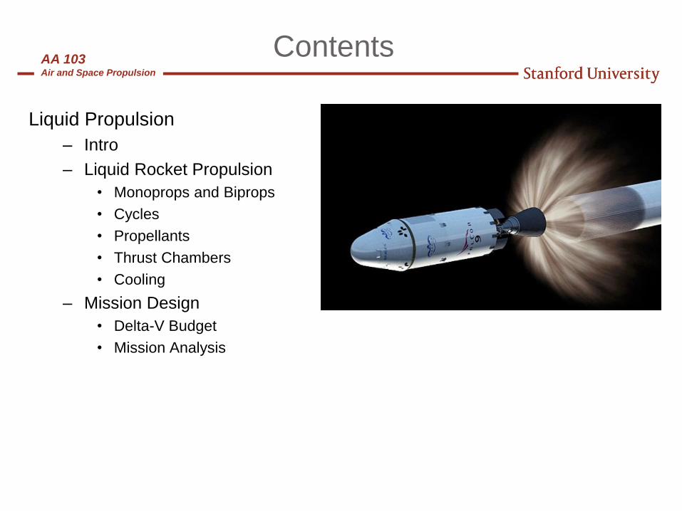
Contents
Liquid Propulsion
– Intro
– Liquid Rocket Propulsion
• Monoprops and Biprops
• Cycles
• Propellants
• Thrust Chambers
• Cooling
– Mission Design
• Delta-V Budget
• Mission Analysis

AA 103Air and Space Propulsion
Liquid Propulsion Pros & Cons
• Advantages
– Highest achievable specific impulse for chemical
propulsion
– Controllability (throttle, pulse)
– Amenable to ground testing ad pre-launch checkout
– Low cost / high reliability
– Enables component redundancy
– Most have relatively clean exhaust
• Disadvantages
– Lower propellant density than solids
– Higher part count than other chemical systems
– More complicated in some cases
– Concerns about leakage / hazards
– Concerns about combustion instability
– Needs mixture ratio control
– Needs special design for zero-g start
3

AA 103Air and Space Propulsion
Monopropellants
• A monopropellant is a single fluid capable of undergoing an exothermic decomposition reaction to yield a gaseous product
• Only a single tank and propellant feed system is required
• Injection is simplified – no mixing required
• Field operations and on-orbit operations (for satellite systems) are simpler
Pressurized
Monopropellant
Fluid Tank Main
Valve Catalyst
Bed
NozzleInjector
Nitrous Oxide Catalyst Bed

AA 103Air and Space Propulsion
5
Decomposition of Monopropellants
• Catalytic decomposition
• Hydrogen peroxide (H2O2):
– Oxidizer
– ISP = 150 s
– 2H2O2 (l) + n H2O (l) → (n+2) H2O (g) + O2 (g) + heat
• Hydrazine (N2H4):
– 3N2H4 → 4 NH3 + N2 + heat
– Followed by ammonia decomposition (endothermic) into N2 and H2
– Most popular: good handling characteristics, relative stability under normal
storage conditions, clean decomposition, ISP = 225-230 s
– For high ISP, attempt to get 30-40% ammonia dissociation
– For gas generator (cooler), up to 80% ammonia dissociation
– Large system: NASA’s Tracking and Data Relay Satellite (TDRS)
• Advanced “monopropellants”: more complex; subject of R&D
AA 103Air and Space Propulsion
6
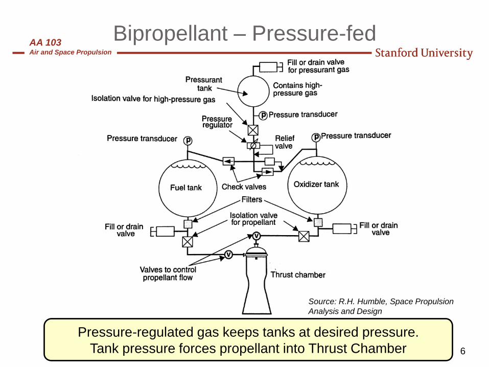
Bipropellant – Pressure-fed
Pressure-regulated gas keeps tanks at desired pressure.
Tank pressure forces propellant into Thrust Chamber
Source: R.H. Humble, Space Propulsion
Analysis and Design

AA 103Air and Space Propulsion
7
Pressure-fed System
Pressure drops continuously from the tank to the nozzle
Source: R.H. Humble, Space Propulsion
Analysis and Design

AA 103Air and Space Propulsion
8
Bipropellant – Turbopump-fed
System contains pump and pump drives.
This figure illustrates a gas generator driving the turbine
Merlin 1D
Vacuum
Merlin 1D
Engine
Source: R.H. Humble, Space Propulsion Analysis and Design

AA 103Air and Space Propulsion
9
Turbopump Engine Cycles
Higher fuel pressure drop between pump outlet and
chamber
Can use “overboard” flow for roll control
These are 3 cycles that most often drive propellant pumps
Source: R.H. Humble, Space Propulsion
Analysis and Design
AA 103Air and Space Propulsion
10
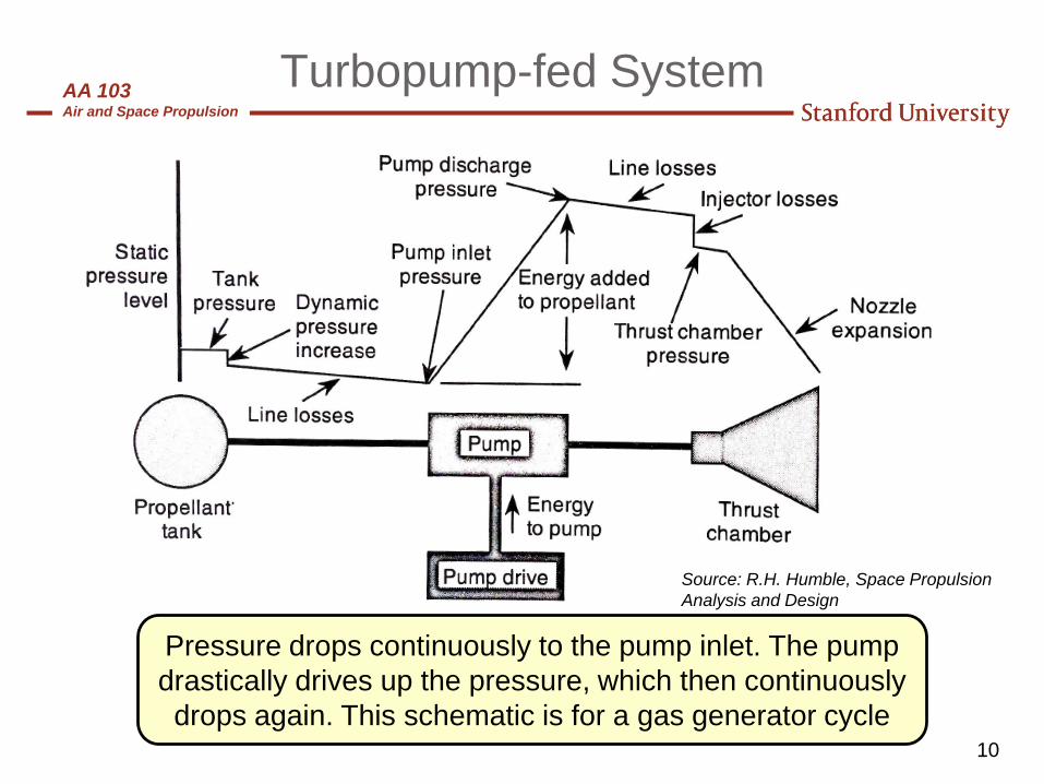
Turbopump-fed System
Pressure drops continuously to the pump inlet. The pump
drastically drives up the pressure, which then continuously
drops again. This schematic is for a gas generator cycle
Source: R.H. Humble, Space Propulsion
Analysis and Design

AA 103Air and Space Propulsion
11
Bipropellant Combustion
• Energetic release of heat as the fuel vapors react with oxidizer vapors to
form combustion products
• As the gas temperatures rise, thermal energy causes dissociation of the
gases
• As the gases expand and cool in the nozzle, re-association and energy
release occurs, but at finite rate - so it is incomplete.
• Jets formed by injection orifices
• Droplets formed by collision of jets,
by ligament breakup of free jets, or
by drag-induced shattering
• Droplets vaporize from heat of
combustion gases
• Further mixing and reaction of
vapors due to diffusion and
turbulent mixingSource: G.P. Sutton, Rocket Propulsion Elements

AA 103Air and Space Propulsion
12
Choosing a Propellant
• Many factors go into choosing a propellant combination
– Performance
– Cost
– Density
– Corrosiveness
– Toxicity
– Stability
– Storability
– Self igniting (hypergolic)
– Lubricity (for turbopumps)
• The choice of mixture ratio to operate the engine at is often a
compromise
– Launch vehicles like O/F that yields higher density for smaller tanks
– Propulsion engineer may choose a lower O/F in order to lower flame
temperature or to accommodate a large amount of film cooling
– O/F may be chosen for equal volume to use identical fuel and ox tanks or to
better package in spacecraft structure
AA 103Air and Space Propulsion
13
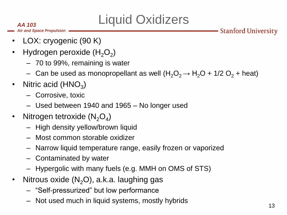
Liquid Oxidizers
• LOX: cryogenic (90 K)
• Hydrogen peroxide (H2O2)
– 70 to 99%, remaining is water
– Can be used as monopropellant as well (H2O2 → H2O + 1/2 O2 + heat)
• Nitric acid (HNO3)
– Corrosive, toxic
– Used between 1940 and 1965 – No longer used
• Nitrogen tetroxide (N2O4)
– High density yellow/brown liquid
– Most common storable oxidizer
– Narrow liquid temperature range, easily frozen or vaporized
– Contaminated by water
– Hypergolic with many fuels (e.g. MMH on OMS of STS)
• Nitrous oxide (N2O), a.k.a. laughing gas
– “Self-pressurized” but low performance
– Not used much in liquid systems, mostly hybrids
AA 103Air and Space Propulsion
14
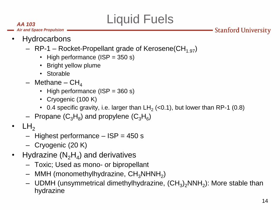
Liquid Fuels
• Hydrocarbons
– RP-1 – Rocket-Propellant grade of Kerosene(CH1.97)
• High performance (ISP = 350 s)
• Bright yellow plume
• Storable
– Methane – CH4
• High performance (ISP = 360 s)
• Cryogenic (100 K)
• 0.4 specific gravity, i.e. larger than LH2 (<0.1), but lower than RP-1 (0.8)
– Propane (C3H8) and propylene (C3H6)
• LH2
– Highest performance – ISP = 450 s
– Cryogenic (20 K)
• Hydrazine (N2H4) and derivatives
– Toxic; Used as mono- or bipropellant
– MMH (monomethylhydrazine, CH3NHNH2)
– UDMH (unsymmetrical dimethylhydrazine, (CH3)2NNH2): More stable than hydrazine

AA 103Air and Space Propulsion
Liquid Oxidizers and Fuels
• Properties of Some Liquid Oxidizers
• Properties of Some Liquid Fuels
15
Source: G.P. Sutton, Rocket Propulsion
Elements
AA 103Air and Space Propulsion
16
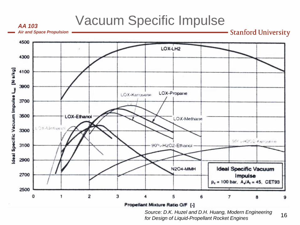
Vacuum Specific Impulse
Source: D.K. Huzel and D.H. Huang, Modern Engineering
for Design of Liquid-Propellant Rocket Engines

AA 103Air and Space Propulsion
Thrust Chamber Assembly

AA 103Air and Space Propulsion
18
Injector Types
• Introduce, meter the propellant flow
– major influence on the performance, chamber heat load, and combustion stability of the engine
– “Black art”: Despite advances with CFD modeling, much of injector design is empirical
• Impinging Elements - form fans of mixed droplet sprays
– Like (e.g. 2 ox.) and unlike doublets
– Like and unlike (e.g. fuel/ox.) triplets
– Splash plate and sheet forming elements
– Pintle injector
– Swirl elements
• Non-impinging elements - Rely on diffusion and turbulence to mix propellants
– Showerhead injector
• Shear Mixing - Rely on velocity difference to mix, usually “gas-liquid” injection
– Coaxial elements - common on LOX/LH2 engines (SSME, RL10, etc.)
Source: G.P. Sutton, Rocket Propulsion
Elements

AA 103Air and Space Propulsion
Liquid Rocket Injector Design – SSME Injector
19
Source: G.P. Sutton, Rocket Propulsion
Elements

AA 103Air and Space Propulsion
20
Acoustic Combustion Instability
• Types of acoustic (high frequency) instability:
– Intrinsic acoustic mode:
• Small propellant flow oscillations
• Determined by coupling between combustion process and chamber acoustics
– Injection coupled acoustic mode
• Coupling between propellant injection process and chamber acoustics
• Frequency of acoustic oscillations (> 1000 Hz) is function of gas speed of
sound and chamber geometry (see Fig. from Huzel and Huang)
• Can result in engine damage in a fraction of a second
Source: D.K. Huzel and D.H. Huang,
Modern Engineering for Design of Liquid-
Propellant Rocket Engines

AA 103Air and Space Propulsion
21
Thrust Chamber Cooling
• The thrust chamber must contain the intense combustion heat
and pressure of the burning rocket propellants
• Core combustion temperatures over 5000 °F are achieved with
most propellant combinations
• Thrust Chamber Cooling Methods
– Film or boundary layer cooling
– Transpiration cooling
– Heat sink
– Adiabatic wall
– Radiation
– Ablative
– Regenerative
AA 103Air and Space Propulsion
22
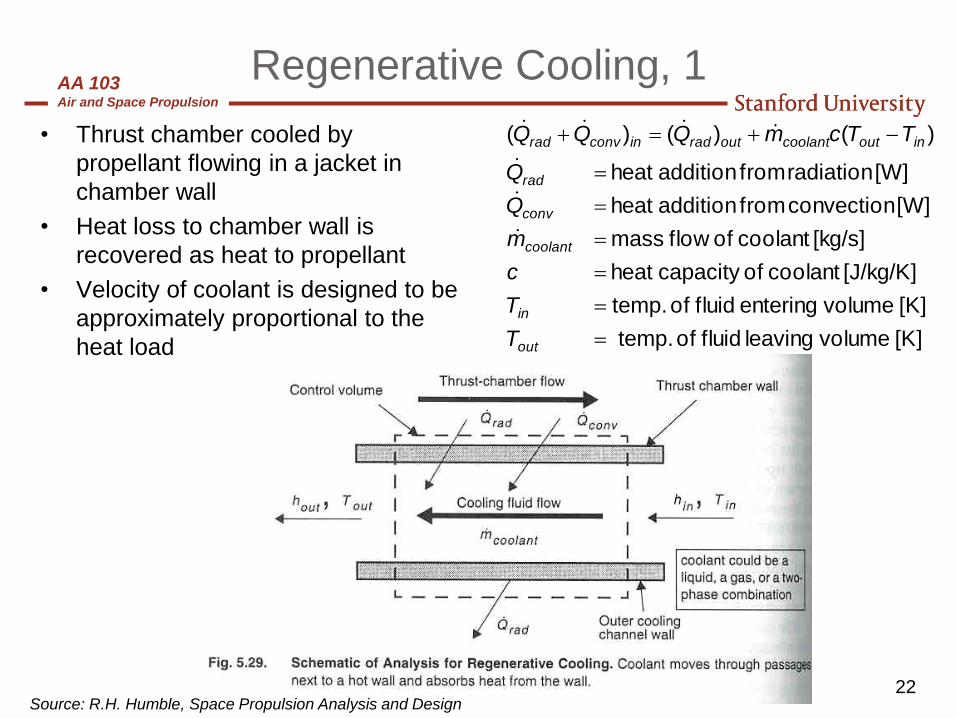
Regenerative Cooling, 1
• Thrust chamber cooled by
propellant flowing in a jacket in
chamber wall
• Heat loss to chamber wall is
recovered as heat to propellant
• Velocity of coolant is designed to be
approximately proportional to the
heat load [K] volume leaving fluid of temp.
[K] volume entering fluid of temp.
[J/kg/K] coolant of capacity heat
[kg/s] coolant offlow mass
[W] convection from addition heat
[W] radiation from addition heat
)()()(
out
in
coolant
conv
rad
inoutcoolantoutradinconvrad
T
T
c
m
Q
Q
TTcmQQQ
Source: R.H. Humble, Space Propulsion Analysis and Design
AA 103Air and Space Propulsion
23
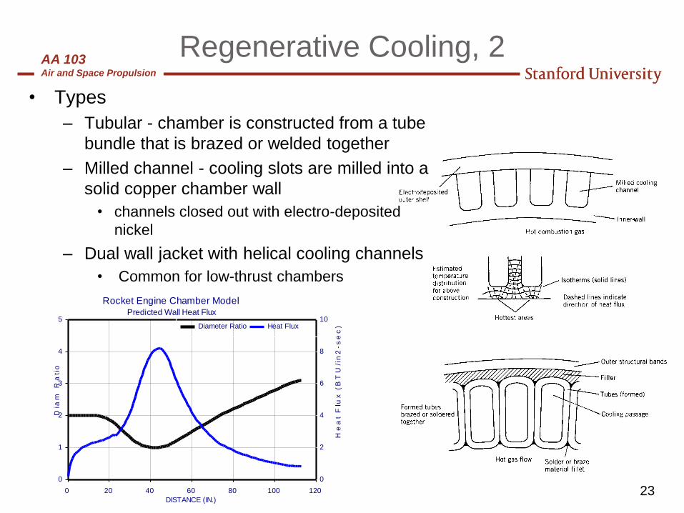
Regenerative Cooling, 2
0
1
2
3
4
5
Dia
m R
ati
o
0
2
4
6
8
10
He
at
Flu
x (
BT
U/i
n2
-s
ec
)
0 20 40 60 80 100 120
DISTANCE (IN.)
Diameter Ratio Heat Flux
Rocket Engine Chamber ModelPredicted Wall Heat Flux
• Types
– Tubular - chamber is constructed from a tube
bundle that is brazed or welded together
– Milled channel - cooling slots are milled into a
solid copper chamber wall
• channels closed out with electro-deposited
nickel
– Dual wall jacket with helical cooling channels
• Common for low-thrust chambers
AA 103Air and Space Propulsion
24
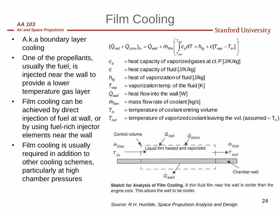
Film Cooling
• A.k.a boundary layer
cooling
• One of the propellants,
usually the fuel, is
injected near the wall to
provide a lower
temperature gas layer
• Film cooling can be
achieved by direct
injection of fuel at wall, or
by using fuel-rich injector
elements near the wall
• Film cooling is usually
required in addition to
other cooling schemes,
particularly at high
chamber pressures
)T (assumed vol. the leaving coolant vaporized of etemperatur
volume entring coolant of etemperatur
[kg/s] coolant of rateflow mass
[W] wallthe intoflow heat
[K] fluid the of temp. onvaporizati
[J/kg] fluid of onvaporizati of heat
[J/K/kg] fluid of capacity heat
[J/K/kg] P ct. at gases vaporized of capacity heat
][)(
C
out
in
film
wall
vap
fg
p
T
T
invapfgpfilmwallinconvrad
T
T
m
Q
T
h
c
c
TTchdTcmQQQout
vap
Source: R.H. Humble, Space Propulsion Analysis and Design
AA 103Air and Space Propulsion
25
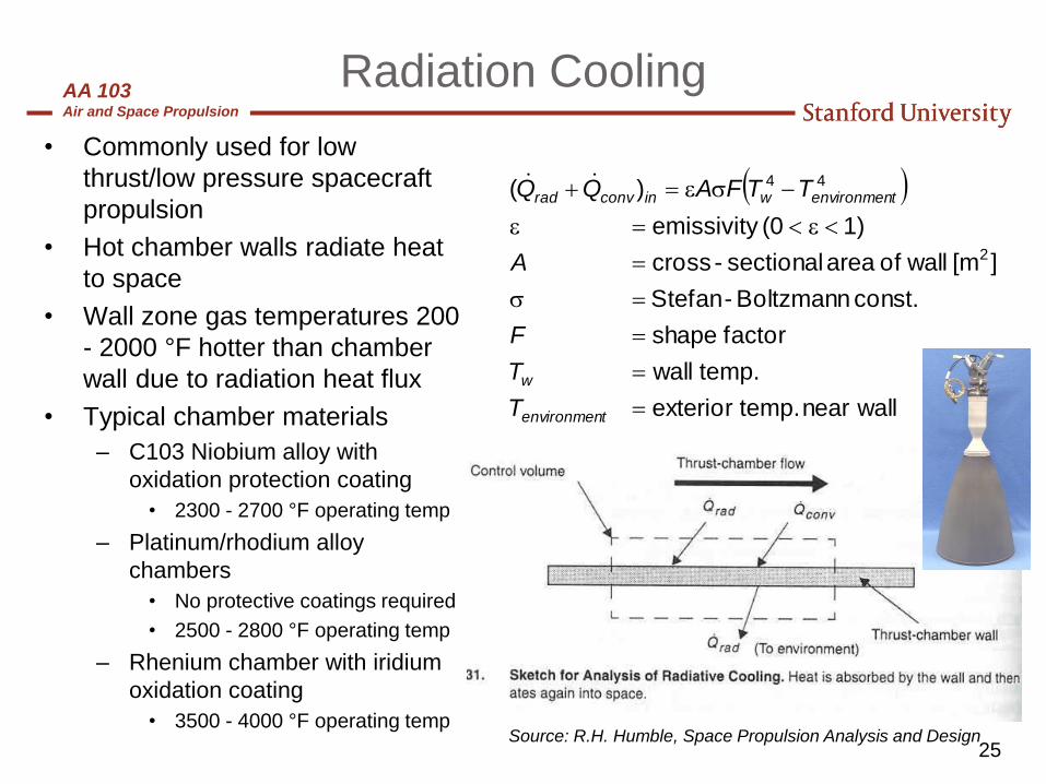
Radiation Cooling
• Commonly used for low
thrust/low pressure spacecraft
propulsion
• Hot chamber walls radiate heat
to space
• Wall zone gas temperatures 200
- 2000 °F hotter than chamber
wall due to radiation heat flux
• Typical chamber materials
– C103 Niobium alloy with
oxidation protection coating
• 2300 - 2700 °F operating temp
– Platinum/rhodium alloy
chambers
• No protective coatings required
• 2500 - 2800 °F operating temp
– Rhenium chamber with iridium
oxidation coating
• 3500 - 4000 °F operating temp
wallnear temp. exterior
temp. wall
factor shape
const. Boltzmann-Stefan
][m wallof area sectional-cross
1)(0 emissivity
)(
2
44
tenvironmen
w
tenvironmenwinconvrad
T
T
F
A
TTFAQQ
Source: R.H. Humble, Space Propulsion Analysis and Design

AA 103Air and Space Propulsion
26
Ablative Cooling
[kg/s] material ablation of enthalpy
[kg/s] material ablative offlow mass
)(
ablative
ablative
ablativeablativeinconvrad
h
m
hmQQ
• Silica fibers in a phenolic resin
matrix that chars and erodes as
it absorbs heat
• Silica fibers provide structural
strength to char layer
– Molten glass layer helps block
oxidation of carbon char layer
• Phenolic matrix pyrolizes into a
carbonaceous char layer,
releases gases that remove heat
and create gas film at surface
Source: R.H. Humble, Space Propulsion Analysis and Design

AA 103Air and Space Propulsion
27
Real Nozzles
• Losses:– Divergence loss (shape)
– Viscous drag loss (B.L.)
– Chemical kinetics loss (non-equilibrium)
– Typical 98.5% efficiency
Low altitude
Over-expanded
High altitude
Under-expanded

AA 103Air and Space Propulsion
28
Ignition Systems
• Proper ignition of a rocket engine is one of the most important aspects
of a rocket test
• Types of Ignition Systems
– Hypergolic
• Use of propellants that self ignite on contact
• Nitrogen Tetroxide and amines (hydrazine, MMH, UDMH, etc.)
– Pyrotechnic Ignition
• Use of a solid propellant squib or grain
• Common in early days of rocketry
– Augmented Spark Igniter (Precombustor ignition)
• Main chamber lit by a separate torch-like combustor fed by some fuel and ox
that is ignited by a spark plug
– Hypergolic slug
• A cartridge of a hypergolic fluid is installed in one feedline so that it is pushed
into chamber by main propellant flow
• Often a pyrophoric fluid is used in the fuel line - ignites with oxygen

AA 103Air and Space Propulsion
29
Typical Configurations
• Large launch vehicle first stage and second stage
– Pump-fed, i.e. light tanks
– Regen engine: metal, such as inconel…
– Possible ablative nozzle extension
– Typ. Pc: 5.5 MPa (800 psia) – 8.5 MPa (1,200 psia) or higher
• Small launch vehicle or upper stage
– Pressure-fed, large portion of blow-down (50% or more), heat exchangers
– Ablative engine: silica/phenolic with carbon over-wrap
– Typ. Pc: 1.0 MPa (150 psia) – 2 MPa (300 psia) or higher
• Spacecraft
– Low chamber pressure
– Pressure-fed
– Typ. Pc: 1.0 MPa (150 psia) – 2 MPa (300 psia)

AA 103Air and Space Propulsion
Mission Analysis

AA 103Air and Space Propulsion
31
Basics of propulsion
• Thrust: Generated by expelling propellant at high speed (momentum
exchange)
Propellants
m
Chamber Nozzle
Vex
pex
patm
pc
exatmexexT AppVmF )(
SL) sec.(@ per burnt propellant of Weight
Thrust
0
0
gm
F
dtmg
dtF
I T
t
t
T
SP
mass final
mass initialln SPIgV
• Specific impulse: total impulse per unit weight of propellant (measures
energy content of propellant and how it is transferred in thrust)
• V & rocket equation:
AA 103Air and Space Propulsion
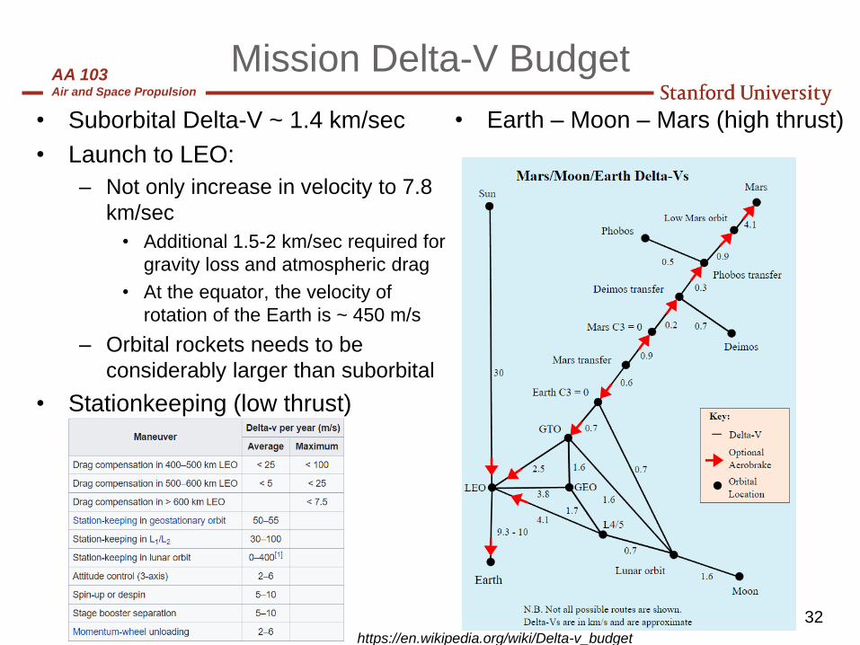
Mission Delta-V Budget
• Suborbital Delta-V ~ 1.4 km/sec
• Launch to LEO:
– Not only increase in velocity to 7.8
km/sec
• Additional 1.5-2 km/sec required for
gravity loss and atmospheric drag
• At the equator, the velocity of
rotation of the Earth is ~ 450 m/s
– Orbital rockets needs to be
considerably larger than suborbital
• Stationkeeping (low thrust)
32
• Earth – Moon – Mars (high thrust)
https://en.wikipedia.org/wiki/Delta-v_budget

AA 103Air and Space Propulsion
33
Mission Analysis, 1
• Payload: usually refers to the
part of the s/c which performs
the mission; for propulsion,
usually refers to the dry mass
“carried” by the propulsion
system
• Wet s/c = payload (or dry s/c) +
prop. syst. + propellant +
pressurant
• Pressurant neglected for
requirements def.
• Depending on mission/type of
propulsion, prop. system mass
(minert) may be small or large
compared to that of the payload
ln
initial mass
final mass
where:
with
s/c dry or payload mass
propellant mass
inert mass of propulsion system
iSP
f
i
f
i pay inert prop f prop
pay
prop
inert
mV gI
m
m
m
m m m m m m
m
m
m

AA 103Air and Space Propulsion
34
Mission Analysis, 2
• Inert mass large for large ΔV mission (carry a
lot of propellant)
• Inert mass fraction:
• Propellant mass fraction:
• For known ΔV, propellant mass as fn. of finert
• Single Stage to Orbit Calculation (example)
– Assume for a LEO mission ΔV = 7500 m/sec
and Isp = 350 sec
– The Rocket Equation yields the mass ratio
mi/mf = 8.88
– Only 11% of the vehicle is structures &
payload (inert mass fraction)
1
inertinert
prop inert
prop
prop inert
prop inert
mf
m m
mf f
m m
1 1
1
SP
SP
V
gI
pay inert
prop V
gI
inert
m e f
m
f e
AA 103Air and Space Propulsion
35
References
• R.H. Humble, G.N. Henry, W.J, Larson, Space Propulsion Analysis and
Design [SPAD], New York : McGraw-Hill, 1995.
• G.P. Sutton and O. Biblarz, Rocket Propulsion Elements, 8th Ed., John
Wiley & Sons, 2010
• V. Yang, M. Habiballah, J. Hulka and M. Popp, Eds., Liquid Rocket
Thrust Chambers; Aspects of Modeling, Analysis , and Design,
Progress in Astronautics and Aeronautics, Vol. 200, 2004
• D.K. Huzel and D.H. Huang, Modern Engineering for Design of Liquid-
Propellant Rocket Engines, AIAA, 1992
• NASA SP-8080 to NASA SP-8025: reports addressing specific
components