DC to AC POWER INVERTERS Pure Sine Wave Output · DC to AC POWER INVERTERS Pure Sine Wave Output...
16
DC to AC POWER INVERTERS Pure Sine Wave Output OWNER’S MANUAL MODELS: 12/1800N 12/2400N 12/3000N 12/3600N MODELS: 12/800N 12/1200N 12/1500N
Transcript of DC to AC POWER INVERTERS Pure Sine Wave Output · DC to AC POWER INVERTERS Pure Sine Wave Output...
DC to AC POWER INVERTERSPure Sine Wave Output
OWNER’S MANUAL
MODELS:12/1800N12/2400N12/3000N12/3600N
MODELS:12/800N12/1200N 12/1500N
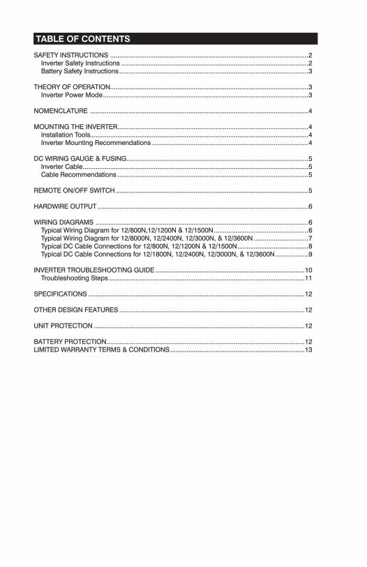
TABLE OF CONTENTS
SAFETY INSTRUCTIONS SAFETY INSTRUCTIONS ............................................................................................................. .............................................................................................................2 Inverter Safety Instructions Inverter Safety Instructions ....................................................................................................... .......................................................................................................2 Battery Safety Instructions Battery Safety Instructions ........................................................................................................ ........................................................................................................3
THEORY OF OPERATIONTHEORY OF OPERATION..........................................................................................................................................................................................................................3 Inverter Power Mode Inverter Power Mode ................................................................................................................. .................................................................................................................3
NOMENCLATURE NOMENCLATURE ........................................................................................................................ ........................................................................................................................4
MOUNTING THE INVERTERMOUNTING THE INVERTER ......................................................................................................... .........................................................................................................4 Installation Tools Installation Tools................................................................................................................................................................................................................................................4 Inverter Mounting Recommendations Inverter Mounting Recommendations ...................................................................................... ......................................................................................4
DC WIRING GAUGE & FUSINGDC WIRING GAUGE & FUSING .................................................................................................... ....................................................................................................5 Inverter Cable Inverter Cable ............................................................................................................................ ............................................................................................................................5 Cable Recommendations Cable Recommendations ......................................................................................................... .........................................................................................................5
REMOTE ON/OFF SWITCHREMOTE ON/OFF SWITCH .......................................................................................................... ..........................................................................................................5
HARDWIRE OUTPUTHARDWIRE OUTPUT .................................................................................................................... ....................................................................................................................6
WIRING DIAGRAMS WIRING DIAGRAMS ..................................................................................................................... .....................................................................................................................6 Typical Wiring Diagram for 12/800N,12/1200N & 12/1500N Typical Wiring Diagram for 12/800N,12/1200N & 12/1500N .................................................... ....................................................6 Typical Wiring Diagram for 12/8000N, 12/2400N, 12/3000N, & 12/3600N Typical Wiring Diagram for 12/8000N, 12/2400N, 12/3000N, & 12/3600N .............................. ..............................7 Typical DC Cable Connections for 12/800N, 12/1200N & 12/1500N Typical DC Cable Connections for 12/800N, 12/1200N & 12/1500N ....................................... .......................................8 Typical DC Cable Connections for 12/1800N, 12/2400N, 12/3000N, & 12/3600N Typical DC Cable Connections for 12/1800N, 12/2400N, 12/3000N, & 12/3600N .................. ..................9
INVERTER TROUBLESHOOTING GUIDEINVERTER TROUBLESHOOTING GUIDE .................................................................................. ..................................................................................1010 Troubleshooting Steps Troubleshooting Steps ............................................................................................................ ............................................................................................................1111
SPECIFICATIONSSPECIFICATIONS ....................................................................................................................... .......................................................................................................................1212
OTHER DESIGN FEATURESOTHER DESIGN FEATURES ...................................................................................................... ......................................................................................................1212
UNIT PROTECTIONUNIT PROTECTION .................................................................................................................... ....................................................................................................................1212
BATTERY PROTECTIONBATTERY PROTECTION ............................................................................................................. .............................................................................................................1212LIMITED WARRANTY TERMS & CONDITIONSLIMITED WARRANTY TERMS & CONDITIONS .......................................................................... ..........................................................................1313
IMPORTANT: Read this manual before installation, it contains important safety, installation, and operating instructions. Save this manual and keep it in a safe place.
NOTE: This product is Listed to applicable UL Standards and requirements by Underwriters Laboratories Inc., File E100666.
Sensata Technologies is an ISO 9001:2008 Registered Company.
Sensata uses the following special notices to provide warning of possible safety related problems which could cause serious injury and to provide information to help prevent dam-age to equipment.
DANGER indicates an imminently hazardous situation which, if not avoided will result in death or serious injury.
WARNING indicates a potentially hazardous situation which, if not avoided, could result in death or serious injury.
CAUTION indicates a potentially hazardous situation which, if not avoided, may result in minor or moderate injury.
CAUTION used without the safety alert symbol indicates a potentially hazardous situa-tion which, if not avoided, may result in property damage.
NOTE is used to notify of installation, operation, or maintenance information that is important but not hazard related.
2
SAFETY INSTRUCTIONS
Inverter Safety Instructions:
WARNING: Power Inverters produce hazardous voltages. To avoid risk of harm or fire, the unit must be properly installed.
WARNING: There are no user serviceable parts inside, do not remove the cover.
WARNING: Power Inverters should not be mounted in a location that may be exposed to rain or spray.
WARNING: Power Inverters should not be installed in a zero clearance enclosure.
WARNING Damage to the Power Inverter will occur if correct polarity is not observed when installing the inverter’s DC input cables.
WARNING: Damage to the Power Inverter will occur if an external AC power source is applied to the inverter’s AC hardwire output.
WARNING: Power Inverters contain a circuit breaker and capacitor that may produce a spark. Do not mount in a confined battery or gas compartment.
WARNING: Be sure the Power Inverter is turned OFF during installation.
(Except 12/1500N - NOT UL Listed)
WARNING: Working in the vicinity of lead-acid batteries is dangerous. There is a risk of acid exposure.
WARNING: Batteries generate explosive gases during operation.
WARNING: There is risk of high current discharge from shorting a battery that can cause fire and explosion. Use insulated tools during installation.
WARNING: Remove all rings, watches, jewelry or other conductive items before working near the batteries.
WARNING: Inspect the batteries once a year for cracks, leaks or swelling.
WARNING: Dispose of the batteries according to local regulations. Do not incinerate batteries; risk of explosion exists.
When the inverter is in “Inverter Power” mode, the green LED “Inverter” will come on. The AC power produced by the inverter comes from the energy stored in the battery bank through a sophisticated electronic inversion process. A transformer, a Metal Oxide Silicon Field Effect Transistors (MOSFET), a filter capacitor and a waveform stabilizer circuit are used to generate clean useful AC power.
Note: The signal output waveform produced by the inverter when in “inverter mode” is pure sinusoidal. It has a total harmonic distortion of less than 5%.
3
Battery Safety Information:
THEORY OF OPERATION
Inverter Power Mode
The “Local On/Off Switch” located on front, or the “Remote On/Off Switch” if used controls the inverter. Both the Local and “Remote On/Off” switches are configured in series. To control the inverter remotely set the “Local On/Off switch” to ON.
The inverter will operate in “inverter mode” only.
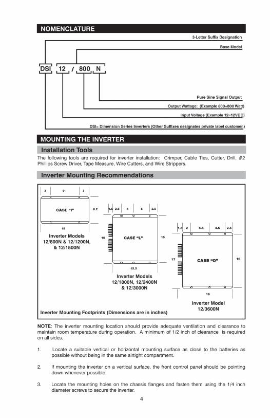
NOMENCLATURE
CASE “L”16
1.5 2.5 4 5 2.5
15
15.5
CASE “I”
3 9 3
8.2
15
CASE “O”17
1.5 2 5.5 4.5 2.5
16
16
MOUNTING THE INVERTER
Installation Tools
Inverter Mounting Recommendations
The following tools are required for inverter installation: Crimper, Cable Ties, Cutter, Drill, #2 Phillips Screw Driver, Tape Measure, Wire Cutters, and Wire Strippers.
Inverter Mounting Footprints (Dimensions are in inches)
Inverter Models12/800N & 12/1200N,
& 12/1500N
Inverter Models12/1800N, 12/2400N
& 12/3000N
Inverter Model12/3600N
4
NOTE: The inverter mounting location should provide adequate ventilation and clearance to maintain room temperature during operation. A minimum of 1/2 inch of clearance is required on all sides.
1. Locate a suitable vertical or horizontal mounting surface as close to the batteries as possible without being in the same airtight compartment.
2. If mounting the inverter on a vertical surface, the front control panel should be pointing down whenever possible.
3. Locate the mounting holes on the chassis flanges and fasten them using the 1/4 inch diameter screws to secure the inverter.
DC WIRE GAUGE, FUSING & BATTERIES
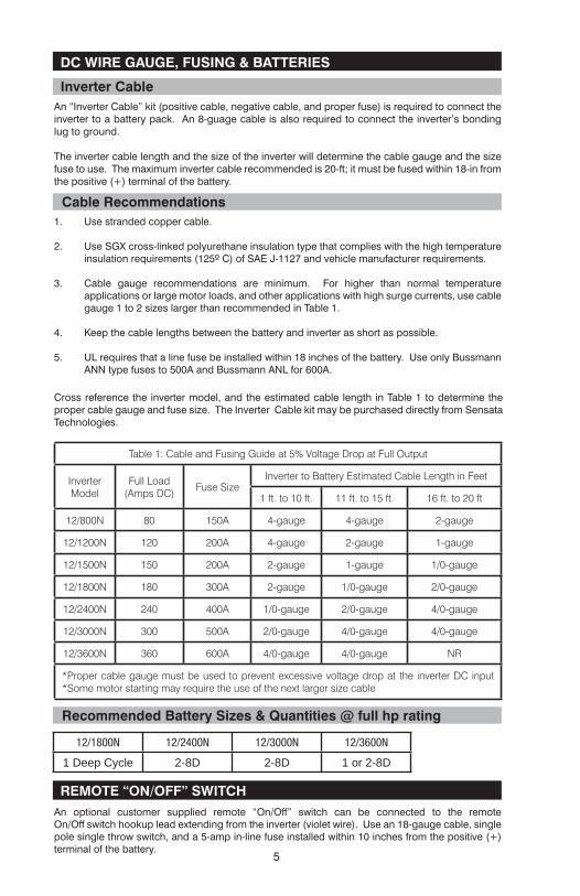
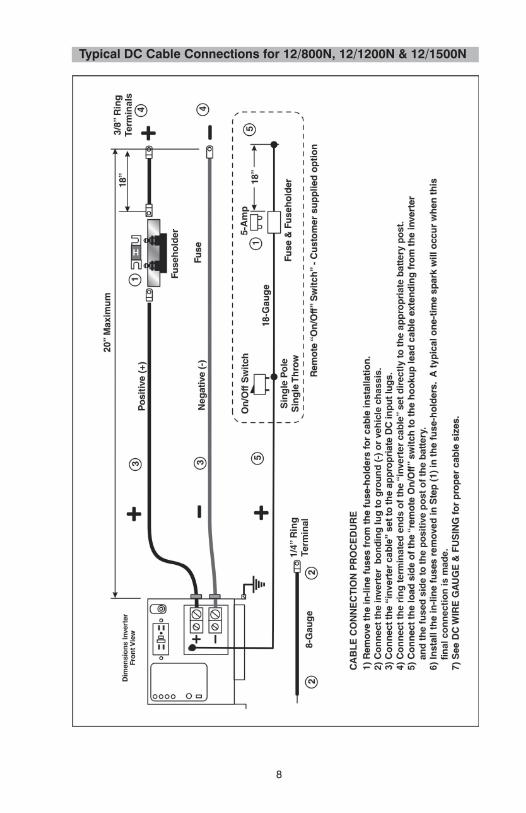
Inverter CableAn “Inverter Cable” kit (positive cable, negative cable, and proper fuse) is required to connect the inverter to a battery pack. An 8-guage cable is also required to connect the inverter’s bonding lug to ground.
The inverter cable length and the size of the inverter will determine the cable gauge and the size fuse to use. The maximum inverter cable recommended is 20-ft; it must be fused within 18-in from the positive (+) terminal of the battery.
Table 1: Cable and Fusing Guide at 5% Voltage Drop at Full Output
Inverter Model
Full Load (Amps DC)
Fuse SizeInverter to Battery Estimated Cable Length in Feet
1 ft. to 10 ft. 11 ft. to 15 ft. 16 ft. to 20 ft
12/800N 80 150A 4-gauge 4-gauge 2-gauge
12/1200N 120 200A 4-gauge 2-gauge 1-gauge
12/1500N 150 200A 2-gauge 1-gauge 1/0-gauge
12/1800N 180 300A 2-gauge 1/0-gauge 2/0-gauge
12/2400N 240 400A 1/0-gauge 2/0-gauge 4/0-gauge
12/3000N 300 500A 2/0-gauge 4/0-gauge 4/0-gauge
12/3600N 360 600A 4/0-gauge 4/0-gauge NR
*Proper cable gauge must be used to prevent excessive voltage drop at the inverter DC input *Some motor starting may require the use of the next larger size cable
Cable Recommendations1. Use stranded copper cable.
2. Use SGX cross-linked polyurethane insulation type that complies with the high temperature insulation requirements (125º C) of SAE J-1127 and vehicle manufacturer requirements.
3. Cable gauge recommendations are minimum. For higher than normal temperature applications or large motor loads, and other applications with high surge currents, use cable gauge 1 to 2 sizes larger than recommended in Table 1.
4. Keep the cable lengths between the battery and inverter as short as possible.
5. UL requires that a line fuse be installed within 18 inches of the battery. Use only Bussmann ANN type fuses to 500A and Bussmann ANL for 600A.
Cross reference the inverter model, and the estimated cable length in Table 1 to determine the proper cable gauge and fuse size. The Inverter Cable kit may be purchased directly from Sensata Technologies.
REMOTE “ON/OFF” SWITCHAn optional customer supplied remote “On/Off” switch can be connected to the remote On/Off switch hookup lead extending from the inverter (violet wire). Use an 18-gauge cable, single pole single throw switch, and a 5-amp in-line fuse installed within 10 inches from the positive (+) terminal of the battery.
5
Recommended Battery Sizes & Quantities @ full hp rating
12/1800N 12/2400N 12/3000N 12/3600N
1 Deep Cycle 2-8D 2-8D 1 or 2-8D
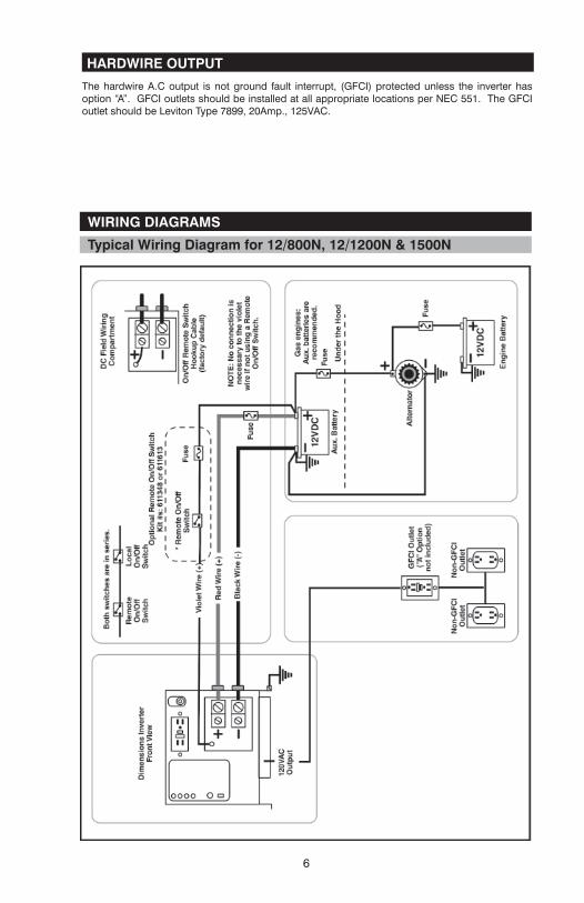
HARDWIRE OUTPUT
The hardwire A.C output is not ground fault interrupt, (GFCI) protected unless the inverter has option “A”. GFCI outlets should be installed at all appropriate locations per NEC 551. The GFCI outlet should be Leviton Type 7899, 20Amp., 125VAC.
WIRING DIAGRAMS
Typical Wiring Diagram for 12/800N, 12/1200N & 1500N
6
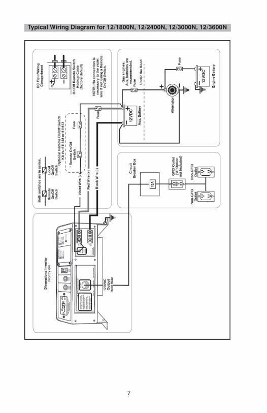
Typical Wiring Diagram for 12/1800N, 12/2400N, 12/3000N, 12/3600N
7
8
Typical DC Cable Connections for 12/800N, 12/1200N & 12/1500N
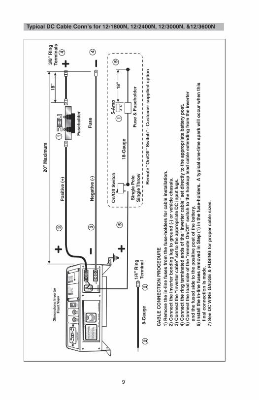
Typical DC Cable Conn’s for 12/1800N, 12/2400N, 12/3000N, &12/3600N
9
10
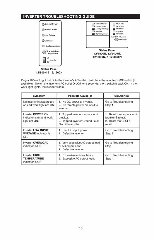
INVERTER TROUBLESHOOTING GUIDE
Status Panel12/800N & 12/1200N
Status Panel12/1800N, 12/2400N,
12/3000N, & 12/3600N
Plug a 100-watt light bulb into the inverter’s AC outlet. Switch on the remote On/Off switch (if available). Switch the inverter’s AC outlet On/Off for 5 seconds: then, switch it back ON. If the work light lights, the inverter works.
Symptom Possible Cause(s) Solution(s)
No inverter indicators are on and work light not ON.
1. No DC power to inverter.2. No remote power on input to inverter.
Go to Troubleshooting Step 1.
Inverter POWER ON indicator is on and work light not ON.
1. Tripped inverter output circuit breaker.2. Tripped inverter Ground Fault Circuit Interupter.
1. Reset the output circuit breaker & retest.2. Reset the GFCI & retest.
Inverter LOW INPUT VOLTAGE indicator is ON.
1. Low DC input power.2. Defective inverter.
Go to Troubleshooting Step 2.
Inverter OVERLOAD indicator is ON.
1. Very excessive AC output load or AC output short.2. Defective inverter.
Go to Troubleshooting Step 3.
Inverter HIGH TEMPERATURE indicator is ON.
1. Excessive ambient temp.2. Excessive AC output load.
Go to Troubleshooting Step 4.
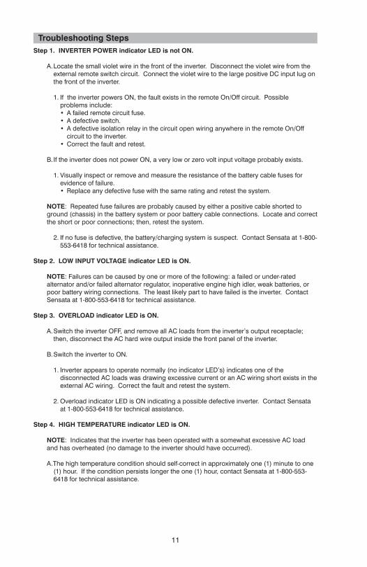
Troubleshooting StepsStep 1. INVERTER POWER indicator LED is not ON.
A. Locate the small violet wire in the front of the inverter. Disconnect the violet wire from the external remote switch circuit. Connect the violet wire to the large positive DC input lug on the front of the inverter.
1. If the inverter powers ON, the fault exists in the remote On/Off circuit. Possible problems include: • A failed remote circuit fuse.• A defective switch.• A defective isolation relay in the circuit open wiring anywhere in the remote On/Off
circuit to the inverter.• Correct the fault and retest.
B. If the inverter does not power ON, a very low or zero volt input voltage probably exists.
1. Visually inspect or remove and measure the resistance of the battery cable fuses for evidence of failure.• Replace any defective fuse with the same rating and retest the system.
NOTE: Repeated fuse failures are probably caused by either a positive cable shorted to ground (chassis) in the battery system or poor battery cable connections. Locate and correct the short or poor connections; then, retest the system.
2. If no fuse is defective, the battery/charging system is suspect. Contact Sensata at 1-800-553-6418 for technical assistance.
Step 2. LOW INPUT VOLTAGE indicator LED is ON.
NOTE: Failures can be caused by one or more of the following: a failed or under-rated alternator and/or failed alternator regulator, inoperative engine high idler, weak batteries, or poor battery wiring connections. The least likely part to have failed is the inverter. Contact Sensata at 1-800-553-6418 for technical assistance.
Step 3. OVERLOAD indicator LED is ON.
A. Switch the inverter OFF, and remove all AC loads from the inverter’s output receptacle; then, disconnect the AC hard wire output inside the front panel of the inverter.
B. Switch the inverter to ON.
1. Inverter appears to operate normally (no indicator LED’s) indicates one of the disconnected AC loads was drawing excessive current or an AC wiring short exists in the external AC wiring. Correct the fault and retest the system.
2. Overload indicator LED is ON indicating a possible defective inverter. Contact Sensata at 1-800-553-6418 for technical assistance.
Step 4. HIGH TEMPERATURE indicator LED is ON.
NOTE: Indicates that the inverter has been operated with a somewhat excessive AC load and has overheated (no damage to the inverter should have occurred).
A. The high temperature condition should self-correct in approximately one (1) minute to one (1) hour. If the condition persists longer the one (1) hour, contact Sensata at 1-800-553-6418 for technical assistance.
11
12
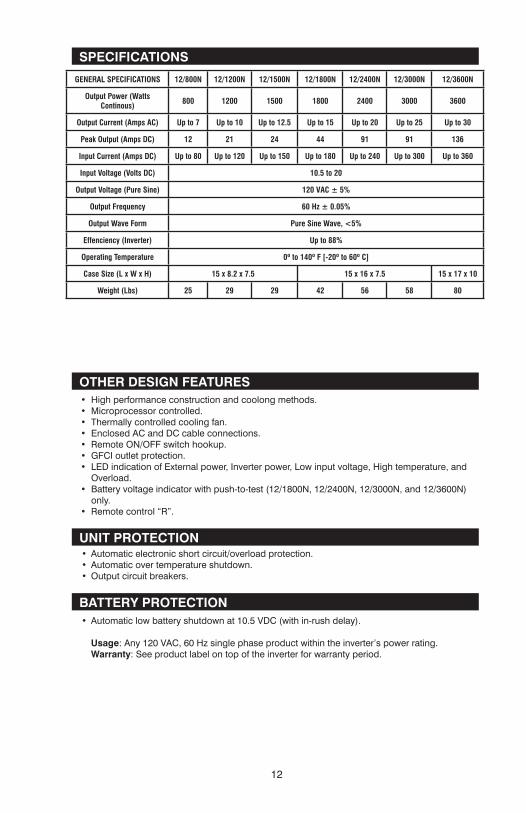
SPECIFICATIONS
GENERAL SPECIFICATIONS 12/800N 12/1200N 12/1500N 12/1800N 12/2400N 12/3000N 12/3600N
Output Power (Watts Continous) 800 1200 1500 1800 2400 3000 3600
Output Current (Amps AC) Up to 7 Up to 10 Up to 12.5 Up to 15 Up to 20 Up to 25 Up to 30
Peak Output (Amps DC) 12 21 24 44 91 91 136
Input Current (Amps DC) Up to 80 Up to 120 Up to 150 Up to 180 Up to 240 Up to 300 Up to 360
Input Voltage (Volts DC) 10.5 to 20
Output Voltage (Pure Sine) 120 VAC ± 5%
Output Frequency 60 Hz ± 0.05%
Output Wave Form Pure Sine Wave, <5%
Effenciency (Inverter) Up to 88%
Operating Temperature 0º to 140º F [-20º to 60º C]
Case Size (L x W x H) 15 x 8.2 x 7.5 15 x 16 x 7.5 15 x 17 x 10
Weight (Lbs) 25 29 29 42 56 58 80
OTHER DESIGN FEATURES
UNIT PROTECTION
BATTERY PROTECTION
• High performance construction and coolong methods.• Microprocessor controlled.• Thermally controlled cooling fan.• Enclosed AC and DC cable connections.• Remote ON/OFF switch hookup.• GFCI outlet protection.• LED indication of External power, Inverter power, Low input voltage, High temperature, and
Overload.• Battery voltage indicator with push-to-test (12/1800N, 12/2400N, 12/3000N, and 12/3600N)
only.• Remote control “R”.
• Automatic electronic short circuit/overload protection.• Automatic over temperature shutdown.• Output circuit breakers.
• Automatic low battery shutdown at 10.5 VDC (with in-rush delay).
Usage: Any 120 VAC, 60 Hz single phase product within the inverter’s power rating.Warranty: See product label on top of the inverter for warranty period.
13
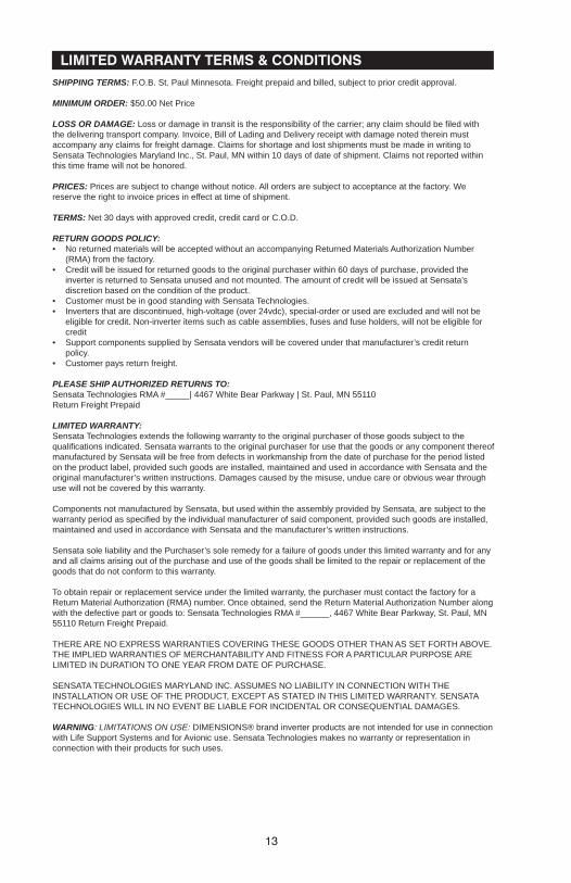
LIMITED WARRANTY TERMS & CONDITIONSSHIPPING TERMS: F.O.B. St. Paul Minnesota. Freight prepaid and billed, subject to prior credit approval.
MINIMUM ORDER: $50.00 Net Price
LOSS OR DAMAGE: Loss or damage in transit is the responsibility of the carrier; any claim should be fi led with the delivering transport company. Invoice, Bill of Lading and Delivery receipt with damage noted therein must accompany any claims for freight damage. Claims for shortage and lost shipments must be made in writing to Sensata Technologies Maryland Inc., St. Paul, MN within 10 days of date of shipment. Claims not reported within this time frame will not be honored.
PRICES: Prices are subject to change without notice. All orders are subject to acceptance at the factory. We reserve the right to invoice prices in effect at time of shipment.
TERMS: Net 30 days with approved credit, credit card or C.O.D.
RETURN GOODS POLICY:• No returned materials will be accepted without an accompanying Returned Materials Authorization Number
(RMA) from the factory.• Credit will be issued for returned goods to the original purchaser within 60 days of purchase, provided the
inverter is returned to Sensata unused and not mounted. The amount of credit will be issued at Sensata’s discretion based on the condition of the product.
• Customer must be in good standing with Sensata Technologies.• Inverters that are discontinued, high-voltage (over 24vdc), special-order or used are excluded and will not be
eligible for credit. Non-inverter items such as cable assemblies, fuses and fuse holders, will not be eligible for credit
• Support components supplied by Sensata vendors will be covered under that manufacturer’s credit return policy.
• Customer pays return freight.
PLEASE SHIP AUTHORIZED RETURNS TO:Sensata Technologies RMA #_____| 4467 White Bear Parkway | St. Paul, MN 55110Return Freight Prepaid
LIMITED WARRANTY:Sensata Technologies extends the following warranty to the original purchaser of those goods subject to the qualifi cations indicated. Sensata warrants to the original purchaser for use that the goods or any component thereof manufactured by Sensata will be free from defects in workmanship from the date of purchase for the period listed on the product label, provided such goods are installed, maintained and used in accordance with Sensata and the original manufacturer’s written instructions. Damages caused by the misuse, undue care or obvious wear through use will not be covered by this warranty.
Components not manufactured by Sensata, but used within the assembly provided by Sensata, are subject to the warranty period as specifi ed by the individual manufacturer of said component, provided such goods are installed, maintained and used in accordance with Sensata and the manufacturer’s written instructions.
Sensata sole liability and the Purchaser’s sole remedy for a failure of goods under this limited warranty and for any and all claims arising out of the purchase and use of the goods shall be limited to the repair or replacement of the goods that do not conform to this warranty.
To obtain repair or replacement service under the limited warranty, the purchaser must contact the factory for a Return Material Authorization (RMA) number. Once obtained, send the Return Material Authorization Number along with the defective part or goods to: Sensata Technologies RMA #______, 4467 White Bear Parkway, St. Paul, MN 55110 Return Freight Prepaid.
THERE ARE NO EXPRESS WARRANTIES COVERING THESE GOODS OTHER THAN AS SET FORTH ABOVE. THE IMPLIED WARRANTIES OF MERCHANTABILITY AND FITNESS FOR A PARTICULAR PURPOSE ARE LIMITED IN DURATION TO ONE YEAR FROM DATE OF PURCHASE.
SENSATA TECHNOLOGIES MARYLAND INC. ASSUMES NO LIABILITY IN CONNECTION WITH THE INSTALLATION OR USE OF THE PRODUCT, EXCEPT AS STATED IN THIS LIMITED WARRANTY. SENSATA TECHNOLOGIES WILL IN NO EVENT BE LIABLE FOR INCIDENTAL OR CONSEQUENTIAL DAMAGES.
WARNING: LIMITATIONS ON USE: DIMENSIONS® brand inverter products are not intended for use in connection with Life Support Systems and for Avionic use. Sensata Technologies makes no warranty or representation in connection with their products for such uses.

14
Notes:

Sensata TechnologiesManufacturer of Dimensions Inverters4467 White Bear ParkwaySt. Paul, MN 55110Phone: 651-653-7000; 800-553-6418Fax: 651-653-7600; [email protected]
Form No. 122187 (08/28/12)© Sensata Technologies 2012Printed in U.S.A.