DC Measuring Amplifier with Data Logger GM 80 - Sensing · Email: [email protected] Technical...
19
Email: [email protected] Technical changes to be reserved 090162j.doc Website: www.lorenz-sensors.com 1 Operating Instruction DC Measuring Amplifier with Data Logger GM 80
Transcript of DC Measuring Amplifier with Data Logger GM 80 - Sensing · Email: [email protected] Technical...

Email: [email protected] Technical changes to be reserved 090162j.doc Website: www.lorenz-sensors.com 1
Operating Instruction
DC Measuring Amplifier with Data Logger
GM 80

Email: [email protected] Technical changes to be reserved 090162j.doc Website: www.lorenz-sensors.com 2
Safety Notes
General References The enclosed operating instruction is intended for technically qualified personnel who has corresponding knowledge in the field of measurement and industrial process & control technology. The precise information about all safety notes contained in this operation manual and warnings, as well as its perfect technical implementation are precondition for the safe installation, the initiation, the secure operation and the maintenance of Lorenz Messtechnik technology devices. For this purpose it is absolutely necessary that all measures are carried out by qualified personnel. All persons concerned with the project planning, installation and service of Lorenz Messtechnik devices, must be familiar to the security concepts in automatic control and should be qualified in this sense. For clarity reasons, the enclosed operating instruction can not represent complete details in all conceivable cases of applications for the handling of Lorenz Messtechnik devices. Further, we cannot consider the entire types of installation, handling and maintenance. If you wish further information or if special problems occur, which were not ,or not at length represented in this operating instruction, contact us, please. The oblivion of the safety notes can and will lead to material damages, body injuries and death. Lorenz Messtechnik devices may only be operated in accordance with the applications described in this operation manual. Built-in devices may only be operated in appropriate installations. With the connection and the initiation of the device, the customer accepts the general sale and delivery conditions of Lorenz Messtechnik. Further, he accepts eventually incomplete operation manuals. The information described is without guarantee. Errors and changes are reserved. Intended Purpose, Improper Usage A Lorenz Messtechnik device is used for displaying, processing and controlling or regulation of processes. It shall not be used as the only tool for the prevention of dangerous states to machines and plants. Machines and plants must be constructed in such a way, that erroneous states can not lead to a dangerous situation for the staff (e.g. by independent limit switches, mechanical locking devices). It must be guaranteed in particular that device-operating errors, its malfunction or it’s breakdown do not lead to great property damages or danger for the staff. Consequently, the device then can be used to prevent the machine or the technical installations from error conditions. It is also important that the use of devices does not endanger precautions for the safety of technical installations. Emergency-off settings must remain effective in all operation modes. Installation Notes Lorenz Messtechnik devices must be installed and connected by compliance with the relevant DIN- and VDE-norms. They must be installed in such manner that an unintentional use is sufficingly excluded. The corresponding hardware and software safety precautions are to be observed in such manner that an interruption of the supply and signal cables cannot lead to an undefined or dangerous state. Supply and signal cables must be installed in such way, that disturbing signals (e.g. inductive or capacitive intersperses) will not cause derogations to the function of Lorenz Messtechnik devices. Disturbance, Maintenance and Repair Notes The devices do not contain parts which can be maintained on the customer side. Repairs shall be carried out by Lorenz Messtechnik exclusively. If assuming that a safe operation of the device is not possible anymore, it must be closed down and protected against unintentional handling immediately. This, in particular, applies:
If the device shows visible damages If the device is no longer operative If parts of the device are loose or slack If the connection cables show visible damages
Furthermore, we point out that all obligations of Lorenz Messtechnik exclusively result from the respective sales contract in which the guarantee has been conclusively settled.

Email: [email protected] Technical changes to be reserved 090162j.doc Website: www.lorenz-sensors.com 3
Brief Description: GM 80 is a DC measuring amplifier for passive or active sensors. A flexible data logger can store up to 3000 measured values with time and date. Mobile operation is possible by battery or accu operation, however, it can also be operated with a power unit. Measuring or logging values are transmitted via an RS-232 interface to a pc or printer. 10 parameter sets for sensors are available. There, in each case, the calibration data , the sensor designation and the physical unit are being stored. Functions such as tare, min./max.-recall and min./max.-delete are available during the measurement procedure. Via a trigger input the data logger or the interface can be controlled externally. If the GM 80 is being delivered with one or more sensors, these sensors will be in-calibrated to the GM 80 and are immediately ready for operation. An assignment of sensors to the corresponding parameter set is documented on the rear of the device. Operation Example: - The GM 80 is switched on by pressing ENTER - Control time and date in SYSTEM menu or adjust if necessary
- Adjust language Call menu 2 SYSTEM – 2.1 LANG. When ENTER button was pressed, the GM 80 is in the selection mode. With keys PLUS and/or MINUS the language can be selected. With ENTER the selected language will be stored. With ESC the selected language will be discarded.
- Adjust time
Call menu 2 SYSTEM – 2.8 DATE. When ENTER button was pressed TIME will appear on the LCD. Press ENTER again and the time can be adjusted. With PLUS and MINUS the hours can be adjusted. After ENTER the minutes can be adjusted with PLUS and MINUS. With ENTER the selected time will be stored. With ESC the selected time will be discarded.
- Change to the measuring mode
From menu 1 MEASUR by pressing ENTER the list of all sensors is called. With PLUS and/or. MINUS a sensor parameter set is being chosen. With ENTER the GM 80 is being adjusted to this sensor parameter set. With ESC it is possible to switch back to menu 1 MEASUR from any mode.
- Change measuring rate by measuring mode
The measuring mode can be left by pressing ESC. After pressing ESC again, the GM 80 will be in menu 1 MEASUR. From there the menu 2 SYSTEM – 2.4 Rate can be called.Select RATE by key PLUS and/or MINUS. By pressing key ENTER the set measuring rate is being displayed first.By key PLUS and/or MINUS a new measuring rate can be adjusted. By ENTER the new measuring rate will be taken over, by ESC the new measuring rate will be discarded.
- Switch off GM 80
GM 80 is switched off, when ESC button is pressed >3 seconds. Key Assignment: Key Menu:
���� Scroll up
���� Scroll down
ENTER Confirmation One step forward in the menu
ESC Discard, one step back in the menu
Email: [email protected] Technical changes to be reserved 090162j.doc Website: www.lorenz-sensors.com 4
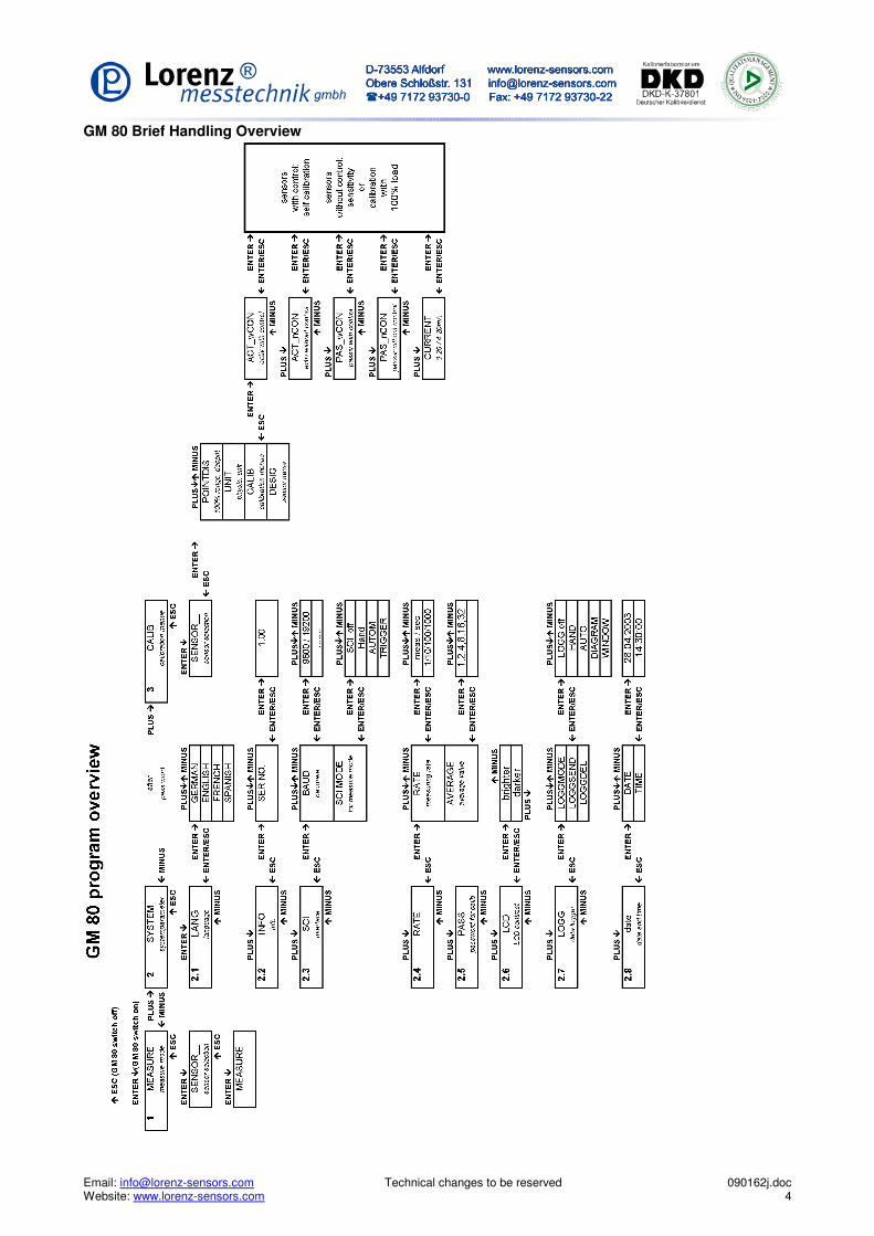
GM 80 Brief Handling Overview

Email: [email protected] Technical changes to be reserved 090162j.doc Website: www.lorenz-sensors.com 5
Measuring with the GM 80: Selected Sensor: Force sensor with measuring range: 200KN
Sensitivity 2mV/V Designation e.g.: Press Parameter set: Sensor no.: 3 Option: 100% Calibration control
In order to be able to now measure with this sensor, the sensor " Press" is selected in the measuring mode. During a measurement, a minimum and maximum value buffer can be called with the MINUS key. The respective displayed minimum or maximum value can be deleted by ENTER. If the measured value shall be sent through an interface to a pc or printer, the baud rate must be adjusted to the receiver and at SCI-MODE the operating mode must be chosen. For example: HAND, a measured value with time is displayed during every keystroke on ENTER while measuring. For data logging, adjust operating mode in the logger mode, e.g. choose AUTO and interval time e.g. 10 sec and change to measuring mode. A measured value with time is now stored every 10 sec. In mode LOGGSEND, these data can then be sent through the interface. Key Assignment: Key Measuring Mode:
���� Press = TARE
���� MEASURING---MIN---MAX--- MEASURING...
ENTER At MEASURING: send data At LOGG: store measured value, if adjusted At MIN: delete MIN At MAX: delete MAX
ESC Back to menu / Press for 3 sec. = Off Parameters of a Sensor: After entering the password (9373) in menu 2SYSTEM-2.5PASS, the sensor can be installed in the calibration menu. Following parameters are possible:
Sensor__l Sensor no. 3 Sensor 0 – 9 possible POINTDIS 200,0 Match meas. range and decimal point (max. 9999) UNIT _kN 1 – 3 digit unit possible DESIGN Press Up to 8 digit name (or numbers) arbitrary CALIB PAS_wCON Select Passive with cal. control. See data sheet of
sensor 0% LOAD Unload sensor 0% value of sensor is assigned to display 0 100% CON Autom. calibration 100% value of sensor is assigned to display
200,0 kN SAVE ENTER or ESC Confirm or discard

Email: [email protected] Technical changes to be reserved 090162j.doc Website: www.lorenz-sensors.com 6
Menu Description: 1 MEASURE: Measuring mode SENSOR__: Sensor selection for measuring mode, sensor 0 - 9 Here the sensor parameter set for the measurement is being selected. The sensor parameter set must match the connected sensor. 2 SYSTEM: All system parameters are being stored in this menu column. 2.1 LANG Language adjustment
The menu language can be chosen in German, English, French or Spanish. 2.2 INFO Information query was configured factory-sided an is not variable.
VERS NO. Software version
2.3 SCI Interface configuration BAUD: Baud rate adjustment must be conform with the receiver (pc or printer).
SCI MODE Interface configuration only refers to the measuring mode, not the logg mode! OFF Interface off HAND At key stroke „ENTER“ the measured value is issued AUTO Interval time, adjustable from 10ms to 1h (at high measuring rate only possible with
highest baud rate) TRIGGER At impulse on trigger input the measured value is issued 2.4 RATE Measuring rate and average value RATE Measuring rate adjustment can be chosen between 1/s and 1000/s. At fast courses
(screw joint, insert press...) always choose a fast measuring rate, e.g. 1000/s, at very slow courses a small rate, e.g. 1/s.
AVERAGE Forming an average value, the numbers indicate by how many measurements an average value is accumulated. Applicable at e.g. vibrations, control oscillations.....
2.5 PASS Password query After entering the password 9373 it is possible to enter menu 3 CALIB . There the sensor parameters can be modified. 2.6 LCD LCD-contrast adjustment If the LCD becomes unreadable by external influences e.g. solar radiation, heat or
cold, the LCD-contrast can be corrected here. 2.7 LOGG Data logger adjustments LOGGMODE Data logger configuration.
OFF Off-switch for logger operation, by this the measuring mode is possible only. HAND At each key stroke on Enter a logg value is being taken over. AUTO Adjustment of the measuring intervals. DIAGRAM With each increasing flank of the trigger signal a logg value is being taken over. WINDOW The window operation is being started by an increasing trigger flank and can only be
finished by a decreasing flank. During this time, measured values will be deposited in the data logger in 1ms raster.
LOGGSEND Logger values are issued through the interface, press ENTER twice LOGGDEL Logger values are deleted, beforehand there will be a safety query whether the buffer
should be deleted. Before deleting please assure that you have received the desired data.
2.8 DATE Date and time adjustment DATE Date TIME Time
Email: [email protected] Technical changes to be reserved 090162j.doc Website: www.lorenz-sensors.com 7
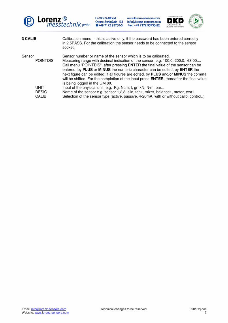
3 CALIB Calibration menu – this is active only, if the password has been entered correctly in 2.5PASS. For the calibration the sensor needs to be connected to the sensor
socket. Sensor__ Sensor number or name of the sensor which is to be calibrated. POINTDIS Measuring range with decimal indication of the sensor, e.g. 100,0; 200,0; 63,00;...
Call menu "POINTDIS", after pressing ENTER the final value of the sensor can be entered, by PLUS or MINUS the numeric character can be edited, by ENTER the next figure can be edited, if all figures are edited, by PLUS and/or MINUS the comma will be shifted. For the completion of the input press ENTER, thereafter the final value is being logged in the GM 80.
UNIT Input of the physical unit, e.g. Kg, Ncm, t, gr, kN, N·m, bar... DESIG Name of the sensor e.g. sensor 1,2,3, silo, tank, mixer, balance1, motor, test1.. CALIB Selection of the sensor type (active, passive, 4-20mA, with or without calib. control..)

Email: [email protected] Technical changes to be reserved 090162j.doc Website: www.lorenz-sensors.com 8
Calibration Procedure: ACT_wCON Active sensor with calibration control following calibration type is possible: 0% load and 100 % load 0% load unload sensor 100%Con thereafter it will be calibrated automatically to 100 % load. SAVE query for takeover of calibration data ACT_nCON Active sensor without calibration control following calibration type is possible: 0% load and 100 % load 0% load and enter 100 % load in V Enter 0% load in V and enter 100 % load in V By pressing PLUS or MINUS a selection between 0%LOAD or NOMINAL VALUE is possible. 0% load unload sensor or NOMVALUE input of the nominal value in V By pressing PLUS or MINUS a selection between 100%LOAD or NOMINAL VALUE is possible. 100%load calibration by 100%LOAD (apply the nominal load) or NOMVALUE input of the nominal value in V SAVE query for takeover of calibration data PAS_wCON Passive sensor with calibration control following calibration type is possible: 0% load and 100 % load 0%LOAD unload sensor 100%Con thereafter it will be calibrated automatically to 100 % load. SAVE query for takeover of calibration data PAS_nCON Passive sensor without calibration control following calibration type is possible: 0% load and 100 % load 0% load and enter 100 % load in mV/V Enter 0% load in mV/V and 100% load in mV/V By pressing PLUS or MINUS a selection between 0%LOAD or NOMINAL VALUE is possible. 0% load unload sensor or NOMVALUE input of the nominal value in mV/V By pressing PLUS or MINUS a selection between 100%LOAD or NOMINAL VALUE is possible. 100%load calibration by 100%LOAD (apply the nominal load) or NOMVALUE input of the nominal value in mV/V SAVE query for takeover of calibration data CURRENT Sensor with 4 - 20mA with following calibration types: 0% load and 100 % load 0% load and enter 100 % load in mA Enter 0% load in mA and 100% load in mA By pressing PLUS or MINUS a selection between 0%LOAD or NOMINAL VALUE is possible. 0% load unload sensor or NOMVALUE input of the nominal value in mA (fixed value 4-20 mA) By pressing PLUS or MINUS a selection between 100%LOAD or NOMINAL VALUE is possible. 100%load calibration by 100%LOAD (apply the nominal load/nominal torque) or NOMVALUE input of the nominal value in mA SAVE query for takeover of calibration data

Email: [email protected] Technical changes to be reserved 090162j.doc Website: www.lorenz-sensors.com 9
Operation via the Serial Interface (SCI): Through the serial interface, measurement values can be issued singly or automatically by the GM 80. The commands can be sent to the GM 80 via a terminal program or PLC. If the GM 80 is in the measuring mode, following commands are available:
ASCII HEX Description 0 0x30 Query continuous measured value (signed integer) 1 0x31 Query maximal value (signed integer) 2 0x32 Query minimal value (signed integer) 3 0x33 Tare display 4 0x34 Reset maximal value 5 0x35 Reset minimal value 6 0x36 Actuate calibration control for sensors with 100 % control resistance 7 0x37 Switch off calibration control for sensors with 100 % control resistance A 0x41 Read-Out datalogger B 0x42 Delete datalogger C 0x43 Read-Out current sensor parameter D 0x44 Read-Out status E 0x45 Read-Out complete status g 0x67 Change protocol setup k 0x6B ENTER l 0x6C PLUS
m 0x6D MINUS n 0x6E ESC
Outside of the measuring mode following commands are available:
ASCII HEX Description A 0x41 Read-Out datalogger C 0x43 Read-Out current sensor parameter D 0x44 Read-Out status E 0x45 Read-Out complete status a 0x61 Write time b 0x62 Read-Out time c 0x63 Write company header d 0x64 Read-Out company header e 0x65 Write all sensor parameters f 0x66 Read-Out all sensor parameters g 0x67 Change protocol setup k 0x6B ENTER l 0x6C PLUS
m 0x6D MINUS n 0x6E ESC

Email: [email protected] Technical changes to be reserved 090162j.doc Website: www.lorenz-sensors.com 10
Read-Out of CurrentSensor Parameters: Sensor designation 8Byte ASCII
Display final value 2Byte packed BCD-figure
Unit 3Byte ASCII
Sensor type and digit 1Byte 0xAB: A ... Sensor type, B ... digit of the dec. point (binary coded) Sensor type: 0xXXXX XXXX |||| 0000 ... active with calibration control 0%load and 100% load calibration 0001 ... active without calibration control 0%load and 100% load calibration 0010 ... active without calibration control 0%load calibration and edit 100%load V 0011 ... active without calibration control edit 0%load V and 100%load V 0100 ... passive with calibration control 0%load and 100% load calibration 0101 ... passive without calibration control 0%load and 100% load calibration 0110 ... passive without calibration control 0%load calibration and edit 100% load in mV/V 0111 ... passive without calibration control edit 0%load and 100% load in mV/V 1000 ... current 0%load and 100% load calibration 1001 ... current 0%load calibration and edit 100%load in mA 1010 ... current edit 0%load mA and 100%load mA Dec. point: 0xXXXX XXXX |||| |000 ... _5000___ |001 ... _5,000__ |010 ... _50,00__ |011 ... _500,0__ |100 ... 5,000___
0%load 2Byte HEX-value (MSB/LSB)
100% load 2Byte HEX- value (MSB/LSB)
Read-Out Status: Status 2Byte general error condition of the GM 80
Read-Out Complete Status: Status 2Byte general error condition of the GM 80
Measuring rate 1Byte 0x01 … 1000/sec 0x02 … 100/sec 0x03 ... 10/sec 0x04 ... 1/sec
Average value 1Byte 0x01 ... x/1 0x02 ... x/2 0x04 ... x/4 0x08 ... x/8 0x10 ... x/16 0x20 ... x/32
SCI_MODE 1Byte 0x00 ... interface off 0x04 … hand mode 0x08 … automatic mode 0x0C … trigger mode
SCI_MODE_DELAY 1Byte 0x02 …10ms 0x03 … 100ms 0x04 … 1s 0x05 … 10s 0x06 ... 1min 0x07 ... 10min 0x08 ... 1h
LOGGMODE 1Byte 0x00 ... logger off 0x04 ... hand mode 0x08 ... automatic mode 0x0C ... graph mode 0x10 ... screen mode
LOGGMODE_DELAY 1Byte 0x01 … 1ms 0x02 …10ms 0x03 … 100ms 0x04 … 1s 0x05 … 10s 0x06 ... 1min 0x07 ... 10min 0x08 ... 1h
Language 1Byte 0x00 ... GERMAN 0x02 ... ENGLISH 0x04 ... FRENCH 0x06 ... SPANISH
Protocol status 1Byte 0xXXXX XXXX (binary coded) |||| |||| |||| |||1 ... do not send conclusion character |||| ||1 ... send CR/LF |||| |1 ... send CR |||| 1 ... send LF

Email: [email protected] Technical changes to be reserved 090162j.doc Website: www.lorenz-sensors.com 11
Read Time: Output:
DAY.MONTH.YEAR 2xspace HOURS:MINUTES:SECONDS
Write Time: The writing is identically with the data block for receipt of time, however, the data block for writing is protected with a checksum and the corresponding weighted checksum. Read Company Header: With this command the company header, which is stored in the GM 80, can be read. Write Company Header: The input is ended either if 256 characters are received or if the character ETX (0x03) Strg-C is contained in the character string. Read all Parameters: The output of all parameters from sensor 1 to sensor 10 occurs in following sequence: Sensor designation Final display value Unit Sensor type (calibration type) / decimal place Calibration values 0% load, 100% load with respectively 2 bytes For this see command read-out of current sensor parameters. Write all Parameters: The write-data block for all sensors is identical to the received read all parameters-data block. However for the writing of sensor parameters a checksum and the corresponding weighted checksum is required. Change of Protocol Setup: Protocol status 1Byte 0xXXXX XXXX (binary coded)
|||| |||| |||| |||1 ... no closing character is sent |||| ||1 ... send CR/LF |||| |1 ... send CR |||| 1 ... send LF
Calculation of the Checksum (CS) and the Weighted Checksum (gewCS) The calculation takes place via all parameter bytes (without the command byte). At the CS all bytes are added (overflows are not considered here). For the calculation of the gewCS the CS is added to the gewCS. At overflow the gewCS is incremented by 1.

Email: [email protected] Technical changes to be reserved 090162j.doc Website: www.lorenz-sensors.com 12
Formatting of the Serial Interface Output Output Format in SCI Mode: HAND: Algebraic sign, measured value, unit, time and CRLF AUTO: 10ms Signed integer and CRLF 100ms Signed integer and CRLF 1s Algebraic sign, measured value, unit, time and CRLF 10s Algebraic sign, measured value, unit, time and CRLF 1min Algebraic sign, measured value, unit, time and CRLF 10min Algebraic sign, measured value, unit, time and CRLF 1h Algebraic sign, measured value, unit, time and CRLF TRIGGER: Signed integer and CRLF Output Format in LOGG Mode: HAND: Algebraic sign, measured value, unit, time and CRLF AUTO: Algebraic sign, measured value,unit and CRLF DIAGRAM: Algebraic sign, measured value,unit and CRLF WINDOW: Algebraic sign, measured value,unit and CRLF Adjustments in the SCI Mode SCI OFF: At this adjustment a transfer of measured values from the GM 80 is disabled. The GM 80 can be controlled however with the GM 80-commands. HAND: In this mode a measured value is issued via the serial interface when the Enter key is pressed at the GM 80. AUTO: In this mode a measured value is issued via the serial interface in the adjusted delay TRIGGER: At a trigger event In this mode, a measured value is written in the logger. Since the trigger pulses may occur in 10ms raster and additional time-logg is not possible. The flank of the trigger pulse must be on HIGH for at least 4ms. Then it must be on LOW for at least 6ms. WINDOW: This mode reacts to increasing, respectively decreasing flanks. With a decreasing flank the logging of the measured values is started. Now the measured values are written in the data logger in 1ms raster. A decreasing flank ends the recording.

Email: [email protected] Technical changes to be reserved 090162j.doc Website: www.lorenz-sensors.com 13
Operation and Function Principle of the GM 80-Data Logger The data logger can, if the GM 80 is not in the measuring mode, be read by the menu option 2,7 LOGG - SENDING or by the command "A" via the interface. Outside of the measuring mode the data logger is deleted only by the menu option 2,7 LOGG - DELETION. If the GM 80 is in the measuring mode, the data logger can be read with the command "A" and be deleted with the command "B". If the measuring mode is being switched on from the menu option 1MEASURING-sensor selection, the starting time of the measurement, the current sensor designation, the final value of the measuring range, the adjusted measuring rate and the logger mode (e.g.: AUTO 1ms) are saved in the logger. NOTE: All previous measured values are deleted here! With the read-out of the data logger via the serial interface different adjustments are sent from the GM 80.
a) Company header
b) Starting time of the measurement
c) Sensor designation
d) Final display value
e) Adjusted measuring rate
f) Adjusted logger mode
g) Thereafter the measured values In the HAND MODE the measured values are always logged with the time. The measured value is logged at the data in the AUTOMODE. A time can be assigned to each measured value by the indicated starting time. Since in GRAPHS and in the WINDOW MODE trigger events smaller than 1sec can occur, an additional time log is not possible. Adjustments in the Logg Mode LOGG OUT: Here the data logger is switched off. The logg mode in the measuring mode is switched to "LOGG OUT" as soon as the entire data logger has been edited. HAND: In this mode a measured value is written into the data logger when the enter key was pressed at the GM 80. By an additional logg of time, there is a time assignment for each measured value. AUTO : In this mode in the adjusted Delay a measured value is written into the data logger. By the stored starting time there is a time assignment for each measured value. GRAPH: In this mode at a trigger event a measured value is written into the logger. Since the trigger pulses occur in 10ms raster, an additional logg of the time is not possible. The flank of the trigger pulse must stand on HIGH for 4ms at least. Afterwards on LOW for at least 6ms. WINDOW: This mode reacts to increasing and/or decreasing flanks. At an increasing flank the logging of the measured values is started. From now on the measured values are written in the data logger with 1ms raster. A decreasing flank ends the recording.
Email: [email protected] Technical changes to be reserved 090162j.doc Website: www.lorenz-sensors.com 14
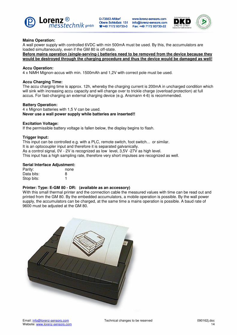
Mains Operation: A wall power supply with controlled 6VDC with min 500mA must be used. By this, the accumulators are loaded simultaneously, even if the GM 80 is off-state. Before mains operation (single-serving-) batteries need to be removed from the device because they would be destroyed through the charging procedure and thus the device would be damaged as well! Accu Operation: 4 x NiMH Mignon-accus with min. 1500mAh and 1,2V with correct pole must be used. Accu Charging Time: The accu charging time is approx. 12h, whereby the charging current is 200mA in uncharged condition which will sink with increasing accu capacity and will change over to trickle charge (overload protection) at full accus. For fast-charging an external charging device (e.g. Ansmann 4-6) is recommended. Battery Operation: 4 x Mignon batteries with 1,5 V can be used. Never use a wall power supply while batteries are inserted!! Excitation Voltage: If the permissible battery voltage is fallen below, the display begins to flash. Trigger Input: This input can be controlled e.g. with a PLC, remote switch, foot switch... or similar. It is an optocoupler input and therefore it is separated galvanically. As a control signal, 0V - 2V is recognized as low level, 3,5V -27V as high level. This input has a high sampling rate, therefore very short impulses are recognized as well. Serial Interface Adjustment: Parity: none Data bits: 8 Stop bits: 1 Printer: Type: E-GM 80 - DR: (available as an accessory) With this small thermal printer and the connection cable the measured values with time can be read out and printed from the GM 80. By the embedded accumulators, a mobile operation is possible. By the wall power supply, the accumulators can be charged, at the same time a mains operation is possible. A baud rate of 9600 must be adjusted at the GM 80.

Email: [email protected] Technical changes to be reserved 090162j.doc Website: www.lorenz-sensors.com 15
Pin Assignment:

Email: [email protected] Technical changes to be reserved 090162j.doc Website: www.lorenz-sensors.com 16
����������������������������������������
� � � � � � �� � � �� � � � � � � �� � � �� � � � � � � �� � � �� � � � � � � �� � � �� Please dispose the unserviceable device according to the legal rules. By this you meet the legal obligations and contribute to the environmental protection! Tendance: The device may be cleaned with a slightly moistened cloth. FAQ – Trouble Shooting
Device can not be turned on Battery/accumulator inserted correctly? Connect power supply at operation with accumulators.
The display begins to flash. Charge the accumulators and/or exchange the batteries.
The calibrated adjustments do not match with the sensor anymore. Was the sensor overloaded?
Is the correct sensor selected? Possibly recalibrate the sensor. Wrong values are indicated after the calibration Was the sensor type selected correctly? At calibration with calibration control check sensor for this option.

Email: [email protected] Technical changes to be reserved 090162j.doc Website: www.lorenz-sensors.com 17
Declaration of Conformity
Herewith it is certified that following defined product corresponds to the substantial protection requirements which were determined in the directive of the European Council for the assimilation of the law of the EC Members regarding the electromagnetic compatibility – EMC - (89/336/EWG).
DC Measuring Amplifier with Data Logger Type: GM 80 handheld device GM 80 - TG GM 80 - PA
For the evaluation of the model range regarding the electromagnetic compatibility the following standard was consulted:
EN61000-6-4:2001 Emitted Interference: (Industrial Environment) EN61000-3-2:2000 Harmonics EN61000-3-3:1995 + A1:2001 Flicker EN61000-6-2:2001 Interference Resistance: (Industrial Environment) EN61000-4-2:1995 + A1:1998 + A2:2001 Discharge of static electricity EN61000-4-3:2002 High-frequency electromagnetic fields EN61000-4-4:1995 + A1:2001 + A2:2001 Fast transient electrical disturbance variables EN61000-4-5:1995 + A1:2001 Surge voltages EN61000-4-6:1996 + A1:2001 Conducted disturbance variables EN61000-4-11:1994 + A1:2001 Voltage drops and voltage fluctuations
This declaration is in exclusive responsibility of the manufacturer
LORENZ Messtechnik GmbH Obere Schlossstrasse 131
73553 Alfdorf
It is guaranteed by internal measures that the standard devices always correspond to the demand of the current EEC guidelines and the applied standards.
In the case of a modification of the product not coordinated with us this declaration loses its validity
Alfdorf, den 18.02.2004 ------------------------------ Geschäftsführer, Peter Lorenz

Email: [email protected] Technical changes to be reserved 090162j.doc Website: www.lorenz-sensors.com 18
.