D.C. Hydraulic Power Systems - DC Hydraulics.comdchydraulics.com/Downloads/Bucher...
108
1/108 Reference: 500−P−000001−E−00 Issue: 04.2010 D.C. Hydraulic Power Systems Compact designs, integrated and manifold valve circuits
Transcript of D.C. Hydraulic Power Systems - DC Hydraulics.comdchydraulics.com/Downloads/Bucher...

1/108
Reference: 500−P−000001−E−00
Issue: 04.2010
D.C. Hydraulic Power SystemsCompact designs, integrated and manifold valve circuits

500−P−000001−E−00/04.2010
2/108

500−P−000001−E−00/04.2010
3/108
Contents Page
1 General information 7 . . . . . . . . . . . . . . . . . . . . . . . . . . . . . . . . . . . . . . . . . . . . . . . . . . . . . . . . . . . . . . . .
1.1 Introduction 7 . . . . . . . . . . . . . . . . . . . . . . . . . . . . . . . . . . . . . . . . . . . . . . . . . . . . . . . . . . . . . . . . . . .
1.2 Mission Statement 7 . . . . . . . . . . . . . . . . . . . . . . . . . . . . . . . . . . . . . . . . . . . . . . . . . . . . . . . . . . . . .
1.3 Quality Policy 7 . . . . . . . . . . . . . . . . . . . . . . . . . . . . . . . . . . . . . . . . . . . . . . . . . . . . . . . . . . . . . . . . .
1.4 Bucher�Hydraulics�Value�Statement 7 . . . . . . . . . . . . . . . . . . . . . . . . . . . . . . . . . . . . . . . . . . . . . .
1.5 Prototype Policy 7 . . . . . . . . . . . . . . . . . . . . . . . . . . . . . . . . . . . . . . . . . . . . . . . . . . . . . . . . . . . . . .
1.6 Features and Benefits 7 . . . . . . . . . . . . . . . . . . . . . . . . . . . . . . . . . . . . . . . . . . . . . . . . . . . . . . . . . .
2 How to Use This Product Guide 8 . . . . . . . . . . . . . . . . . . . . . . . . . . . . . . . . . . . . . . . . . . . . . . . . . . . . .
2.1 M Series D.C. Power System Selection Guide 9 . . . . . . . . . . . . . . . . . . . . . . . . . . . . . . . . . . . .
3 D.C. Hydraulic Power Systems 11 . . . . . . . . . . . . . . . . . . . . . . . . . . . . . . . . . . . . . . . . . . . . . . . . . . . . . .
3.1 Model M−3226 Mini System (Formerly M−255) 11 . . . . . . . . . . . . . . . . . . . . . . . . . . . . . . . . . . . . .
3.2 Model M−3326 Dyna−Jack�® (Formerly M−326) 12 . . . . . . . . . . . . . . . . . . . . . . . . . . . . . . . . . . . . .
3.3 Model M−3304 Dyna−Jack�® (Formerly M−304) 13 . . . . . . . . . . . . . . . . . . . . . . . . . . . . . . . . . . . . .
3.4 Model M−3504 Dyna−Jack�® 14 . . . . . . . . . . . . . . . . . . . . . . . . . . . . . . . . . . . . . . . . . . . . . . . . . . . .
3.5 Model M−3301 Dyna−Jack�® (Formerly M−301) 15 . . . . . . . . . . . . . . . . . . . . . . . . . . . . . . . . . . . . .
3.6 Model M−3311 Dyna−Jack�® (Formerly M−311) 16 . . . . . . . . . . . . . . . . . . . . . . . . . . . . . . . . . . . . .
3.7 Model M−3313 Dyna−Jack�® (Formerly M−313) 17 . . . . . . . . . . . . . . . . . . . . . . . . . . . . . . . . . . . . .
3.8 Model M−721 Dyna−Chute�® 18 . . . . . . . . . . . . . . . . . . . . . . . . . . . . . . . . . . . . . . . . . . . . . . . . . . . .
3.9 Model M−3219 W/PCFC Mini System (Formerly M−258) 19 . . . . . . . . . . . . . . . . . . . . . . . . . . . . .
3.10 Model M−3219 Mini System (Formerly M−259) 20 . . . . . . . . . . . . . . . . . . . . . . . . . . . . . . . . . . . . .
3.11 Model M−3319 Dyna−Jack�® (Formerly M−319) 21 . . . . . . . . . . . . . . . . . . . . . . . . . . . . . . . . . . . . .
3.12 Model M−3519 Dyna−Jack�® 22 . . . . . . . . . . . . . . . . . . . . . . . . . . . . . . . . . . . . . . . . . . . . . . . . . . . .
3.13 Model M−3519−HF Dyna−Jack�® 23 . . . . . . . . . . . . . . . . . . . . . . . . . . . . . . . . . . . . . . . . . . . . . . . . .
3.14 Model M−3505 Dyna−Jack�® (Formerly M−3515) 24 . . . . . . . . . . . . . . . . . . . . . . . . . . . . . . . . . . .
3.15 Model M−3506 Dyna−Jack�® (Formerly M−3516) 25 . . . . . . . . . . . . . . . . . . . . . . . . . . . . . . . . . . .
3.16 Model M−3314 Dyna−Jack�® (Formerly M−314) 26 . . . . . . . . . . . . . . . . . . . . . . . . . . . . . . . . . . . . .
3.17 Model M−3303 Dyna−Jack�® (Formerly M−303) 27 . . . . . . . . . . . . . . . . . . . . . . . . . . . . . . . . . . . . .
3.18 Model M−719 Dyna−Jack�® 28 . . . . . . . . . . . . . . . . . . . . . . . . . . . . . . . . . . . . . . . . . . . . . . . . . . . . .
3.19 Model M−3310 Dyna−Jack�® (Formerly M−310) 29 . . . . . . . . . . . . . . . . . . . . . . . . . . . . . . . . . . . . .
3.20 Model M−3541 Dyna−Jack�® 30 . . . . . . . . . . . . . . . . . . . . . . . . . . . . . . . . . . . . . . . . . . . . . . . . . . . .
3.21 Model M−3542 Dyna−Jack�® 31 . . . . . . . . . . . . . . . . . . . . . . . . . . . . . . . . . . . . . . . . . . . . . . . . . . . .
3.22 Model M−3534 Dyna−Jack�® 32 . . . . . . . . . . . . . . . . . . . . . . . . . . . . . . . . . . . . . . . . . . . . . . . . . . . .
3.23 Model M−3547 Dyna−Jack�® 33 . . . . . . . . . . . . . . . . . . . . . . . . . . . . . . . . . . . . . . . . . . . . . . . . . . . .
3.24 Model M−3551 Dyna−Jack�® 34 . . . . . . . . . . . . . . . . . . . . . . . . . . . . . . . . . . . . . . . . . . . . . . . . . . . .
3.25 Model M−3551−HF Dyna−Jack�® (High Flow) 35 . . . . . . . . . . . . . . . . . . . . . . . . . . . . . . . . . . . . . .
3.26 Model M−3554 Dyna−Jack�® 36 . . . . . . . . . . . . . . . . . . . . . . . . . . . . . . . . . . . . . . . . . . . . . . . . . . . .
3.27 Model M−3552 Dyna−Jack�® 37 . . . . . . . . . . . . . . . . . . . . . . . . . . . . . . . . . . . . . . . . . . . . . . . . . . . .
3.28 Model M−642 Dyna Ramic ® 38 . . . . . . . . . . . . . . . . . . . . . . . . . . . . . . . . . . . . . . . . . . . . . . . . . . . .

500−P−000001−E−00/04.2010
4/108
3.29 Model M−500−4W/3W Dyna−Jack�® 39 . . . . . . . . . . . . . . . . . . . . . . . . . . . . . . . . . . . . . . . . . . . . . .
3.30 Model M−683 Dyna Ramic ® 40 . . . . . . . . . . . . . . . . . . . . . . . . . . . . . . . . . . . . . . . . . . . . . . . . . . . .
3.31 Model M−3528 Dyna−Jack�® 41 . . . . . . . . . . . . . . . . . . . . . . . . . . . . . . . . . . . . . . . . . . . . . . . . . . . .
3.32 Model M−3529 Dyna−Jack�® 42 . . . . . . . . . . . . . . . . . . . . . . . . . . . . . . . . . . . . . . . . . . . . . . . . . . . .
3.33 Model M−3593 Dyna−Jack�® 43 . . . . . . . . . . . . . . . . . . . . . . . . . . . . . . . . . . . . . . . . . . . . . . . . . . . .
3.34 Modular Power Units 44 . . . . . . . . . . . . . . . . . . . . . . . . . . . . . . . . . . . . . . . . . . . . . . . . . . . . . . . . . .
3.35 How to Order Your Modular Power Unit 47 . . . . . . . . . . . . . . . . . . . . . . . . . . . . . . . . . . . . . . . . . . .
3.36 S−326 Pump/Motor Units 48 . . . . . . . . . . . . . . . . . . . . . . . . . . . . . . . . . . . . . . . . . . . . . . . . . . . . . . .
3.37 Dimensional Information for S−326 Pump/Motor Units 49 . . . . . . . . . . . . . . . . . . . . . . . . . . . . . .
3.38 SAE AA Pump Data 50 . . . . . . . . . . . . . . . . . . . . . . . . . . . . . . . . . . . . . . . . . . . . . . . . . . . . . . . . . . .
3.39 SAE A Pump Data 50 . . . . . . . . . . . . . . . . . . . . . . . . . . . . . . . . . . . . . . . . . . . . . . . . . . . . . . . . . . . .
3.40 How to Order S−326 Pump/Motor Units 50 . . . . . . . . . . . . . . . . . . . . . . . . . . . . . . . . . . . . . . . . . . .
3.41 M Series D.C. Pump Data 51 . . . . . . . . . . . . . . . . . . . . . . . . . . . . . . . . . . . . . . . . . . . . . . . . . . . . . .
3.42 Performance Curve AA 52 . . . . . . . . . . . . . . . . . . . . . . . . . . . . . . . . . . . . . . . . . . . . . . . . . . . . . . . .
3.43 Performance Curve AB 52 . . . . . . . . . . . . . . . . . . . . . . . . . . . . . . . . . . . . . . . . . . . . . . . . . . . . . . . .
3.44 Performance Curve AC 53 . . . . . . . . . . . . . . . . . . . . . . . . . . . . . . . . . . . . . . . . . . . . . . . . . . . . . . . .
3.45 Performance Curve AD 53 . . . . . . . . . . . . . . . . . . . . . . . . . . . . . . . . . . . . . . . . . . . . . . . . . . . . . . . .
3.46 Performance Curve AE 54 . . . . . . . . . . . . . . . . . . . . . . . . . . . . . . . . . . . . . . . . . . . . . . . . . . . . . . . .
3.47 Performance Curve AF 54 . . . . . . . . . . . . . . . . . . . . . . . . . . . . . . . . . . . . . . . . . . . . . . . . . . . . . . . . .
3.48 Performance Curve AG 55 . . . . . . . . . . . . . . . . . . . . . . . . . . . . . . . . . . . . . . . . . . . . . . . . . . . . . . . .
3.49 Performance Curve AH 55 . . . . . . . . . . . . . . . . . . . . . . . . . . . . . . . . . . . . . . . . . . . . . . . . . . . . . . . .
3.50 Performance Curve AI 56 . . . . . . . . . . . . . . . . . . . . . . . . . . . . . . . . . . . . . . . . . . . . . . . . . . . . . . . . .
3.51 Performance Curve AJ 56 . . . . . . . . . . . . . . . . . . . . . . . . . . . . . . . . . . . . . . . . . . . . . . . . . . . . . . . . .
3.52 Performance Curve AK 57 . . . . . . . . . . . . . . . . . . . . . . . . . . . . . . . . . . . . . . . . . . . . . . . . . . . . . . . .
4 Birotational Hydraulic Power Systems 58 . . . . . . . . . . . . . . . . . . . . . . . . . . . . . . . . . . . . . . . . . . . . . . .
4.1 Birotational i − Pump 58 . . . . . . . . . . . . . . . . . . . . . . . . . . . . . . . . . . . . . . . . . . . . . . . . . . . . . . . . . . .
4.2 Model M−3504 59 . . . . . . . . . . . . . . . . . . . . . . . . . . . . . . . . . . . . . . . . . . . . . . . . . . . . . . . . . . . . . . . .
4.3 Model M−3530 60 . . . . . . . . . . . . . . . . . . . . . . . . . . . . . . . . . . . . . . . . . . . . . . . . . . . . . . . . . . . . . . . .
4.4 Model M−3547 61 . . . . . . . . . . . . . . . . . . . . . . . . . . . . . . . . . . . . . . . . . . . . . . . . . . . . . . . . . . . . . . . .
5 Dim. Information for Standard D.C. Motors with Performance Curves 62 . . . . . . . . . . . . . . . . . .
5.1 M Series D.C. Motor Information 62 . . . . . . . . . . . . . . . . . . . . . . . . . . . . . . . . . . . . . . . . . . . . . . . .
5.2 08053 D.C. Motor Information 63 . . . . . . . . . . . . . . . . . . . . . . . . . . . . . . . . . . . . . . . . . . . . . . . . . . .
5.3 08111 D.C. Motor Information 64 . . . . . . . . . . . . . . . . . . . . . . . . . . . . . . . . . . . . . . . . . . . . . . . . . . .
5.4 08058 D.C. Motor Information 65 . . . . . . . . . . . . . . . . . . . . . . . . . . . . . . . . . . . . . . . . . . . . . . . . . . .
5.5 18442 D.C. Motor Information 66 . . . . . . . . . . . . . . . . . . . . . . . . . . . . . . . . . . . . . . . . . . . . . . . . . . .
5.6 08196 D.C. Motor Information (Replaces 08100) 67 . . . . . . . . . . . . . . . . . . . . . . . . . . . . . . . . . . .
5.7 08050 D.C. Motor Information 68 . . . . . . . . . . . . . . . . . . . . . . . . . . . . . . . . . . . . . . . . . . . . . . . . . . .
5.8 08163 D.C. Motor Information 69 . . . . . . . . . . . . . . . . . . . . . . . . . . . . . . . . . . . . . . . . . . . . . . . . . . .
5.9 08164 D.C. Motor Information 70 . . . . . . . . . . . . . . . . . . . . . . . . . . . . . . . . . . . . . . . . . . . . . . . . . . .
5.10 08045 D.C. Motor Information 71 . . . . . . . . . . . . . . . . . . . . . . . . . . . . . . . . . . . . . . . . . . . . . . . . . . .
500−P−000001−E−00/04.2010
5/108
5.11 08030 D.C. Motor Information 72 . . . . . . . . . . . . . . . . . . . . . . . . . . . . . . . . . . . . . . . . . . . . . . . . . . .
5.12 08004 D.C. Motor Information 73 . . . . . . . . . . . . . . . . . . . . . . . . . . . . . . . . . . . . . . . . . . . . . . . . . . .
5.13 08189 D.C. Motor Information 74 . . . . . . . . . . . . . . . . . . . . . . . . . . . . . . . . . . . . . . . . . . . . . . . . . . .
5.14 08066 D.C. Motor Information 75 . . . . . . . . . . . . . . . . . . . . . . . . . . . . . . . . . . . . . . . . . . . . . . . . . . .
5.15 08051 D.C. Motor Information 76 . . . . . . . . . . . . . . . . . . . . . . . . . . . . . . . . . . . . . . . . . . . . . . . . . . .
5.16 08120 D.C. Motor Information 77 . . . . . . . . . . . . . . . . . . . . . . . . . . . . . . . . . . . . . . . . . . . . . . . . . . .
5.17 08035 D.C. Motor Information 78 . . . . . . . . . . . . . . . . . . . . . . . . . . . . . . . . . . . . . . . . . . . . . . . . . . .
5.18 08195 D.C. Motor Information 79 . . . . . . . . . . . . . . . . . . . . . . . . . . . . . . . . . . . . . . . . . . . . . . . . . . .
5.19 08168 D.C. Motor Information 80 . . . . . . . . . . . . . . . . . . . . . . . . . . . . . . . . . . . . . . . . . . . . . . . . . . .
5.20 08055 D.C. Motor Information 81 . . . . . . . . . . . . . . . . . . . . . . . . . . . . . . . . . . . . . . . . . . . . . . . . . . .
5.21 08040 D.C. Motor Information 82 . . . . . . . . . . . . . . . . . . . . . . . . . . . . . . . . . . . . . . . . . . . . . . . . . . .
5.22 08055 D.C. Motor Information 83 . . . . . . . . . . . . . . . . . . . . . . . . . . . . . . . . . . . . . . . . . . . . . . . . . . .
5.23 08174 D.C. Motor Information 84 . . . . . . . . . . . . . . . . . . . . . . . . . . . . . . . . . . . . . . . . . . . . . . . . . . .
5.24 Motor Thermal Performance Data 85 . . . . . . . . . . . . . . . . . . . . . . . . . . . . . . . . . . . . . . . . . . . . . . .
6 M Series Reservoirs 86 . . . . . . . . . . . . . . . . . . . . . . . . . . . . . . . . . . . . . . . . . . . . . . . . . . . . . . . . . . . . . . .
6.1 M−Series Reservoirs Steel 86 . . . . . . . . . . . . . . . . . . . . . . . . . . . . . . . . . . . . . . . . . . . . . . . . . . . . .
6.2 M−Series Reservoirs Poly 89 . . . . . . . . . . . . . . . . . . . . . . . . . . . . . . . . . . . . . . . . . . . . . . . . . . . . . .
6.3 M−Series Reservoirs Poly 5.5˜x6.5˜ Top 90 . . . . . . . . . . . . . . . . . . . . . . . . . . . . . . . . . . . . . . . . . .
6.4 M−Series Reservoirs Poly 6˜ Centered 91 . . . . . . . . . . . . . . . . . . . . . . . . . . . . . . . . . . . . . . . . . . .
6.5 M−Series Reservoirs Poly 6˜ Offset 92 . . . . . . . . . . . . . . . . . . . . . . . . . . . . . . . . . . . . . . . . . . . . . .
6.6 M−Series Reservoirs Poly 6.75˜x6.75˜ 93 . . . . . . . . . . . . . . . . . . . . . . . . . . . . . . . . . . . . . . . . . . .
6.7 M−Series Reservoirs Poly 9˜x10˜ 94 . . . . . . . . . . . . . . . . . . . . . . . . . . . . . . . . . . . . . . . . . . . . . . . .
6.8 Reservoirs for Mini Units Poly 3.5"x3.5" MINI 95 . . . . . . . . . . . . . . . . . . . . . . . . . . . . . . . . . . . . .
6.9 Reservoirs for Mini Units Poly 3.5"x5.38" MINI 96 . . . . . . . . . . . . . . . . . . . . . . . . . . . . . . . . . . . .
6.10 Valves for DC Systems 97 . . . . . . . . . . . . . . . . . . . . . . . . . . . . . . . . . . . . . . . . . . . . . . . . . . . . . . . . .
6.11 Motor Start Switches for D.C. Power Systems 99 . . . . . . . . . . . . . . . . . . . . . . . . . . . . . . . . . . . . .
6.12 Control Boxes 100 . . . . . . . . . . . . . . . . . . . . . . . . . . . . . . . . . . . . . . . . . . . . . . . . . . . . . . . . . . . . . . . .
6.13 Mounting Brackets 101 . . . . . . . . . . . . . . . . . . . . . . . . . . . . . . . . . . . . . . . . . . . . . . . . . . . . . . . . . . . .
6.14 Popular Accessories For DC Power Systems 102 . . . . . . . . . . . . . . . . . . . . . . . . . . . . . . . . . . . . .
6.15 Monarch Hand Pumps 103 . . . . . . . . . . . . . . . . . . . . . . . . . . . . . . . . . . . . . . . . . . . . . . . . . . . . . . . . .
6.16 Standard Hand Pumps 103 . . . . . . . . . . . . . . . . . . . . . . . . . . . . . . . . . . . . . . . . . . . . . . . . . . . . . . . . .
6.17 High Pressure − Low Displacement Hand Pump 104 . . . . . . . . . . . . . . . . . . . . . . . . . . . . . . . . . . .
6.18 High Pressure − Heavy Duty Hand Pump 105 . . . . . . . . . . . . . . . . . . . . . . . . . . . . . . . . . . . . . . . . .
6.19 Heavy Duty Remote Hand Pump 106 . . . . . . . . . . . . . . . . . . . . . . . . . . . . . . . . . . . . . . . . . . . . . . . .
6.20 Model H−100 Series Hand Pumps With Reservoirs 106 . . . . . . . . . . . . . . . . . . . . . . . . . . . . . . . . .
6.21 Battery Cables 107 . . . . . . . . . . . . . . . . . . . . . . . . . . . . . . . . . . . . . . . . . . . . . . . . . . . . . . . . . . . . . . . .
6.22 Limited 1 Year Warranty 108 . . . . . . . . . . . . . . . . . . . . . . . . . . . . . . . . . . . . . . . . . . . . . . . . . . . . . . . .

500−P−000001−E−00/04.2010
6/108

500−P−000001−E−00/04.2010
7/108
1 General information
1.1 Introduction
This catalogue illustrates the technical specifications for
Bucher Hydraulic’s D.C. range of Hydraulic Power Units.Designed for campactness and durability, millions of M
Series systems have been sold worldwide for actuating mo-
bile, material handling, transport, construction, defense, ac-
cess, machine tool, ergonomic, and other labor saving de-
vices.The Bucher Hydraulic name is synonymous with precise
and cost efficient designs, robust construction and rapid
backup service. For over 150 years the company continues
to strive for your confidence by offering personal, reliable
service and �Quality Machinery Since 1856" to customers
in over 37 countries.
1.2 Mission Statement
Bucher Hydraulics designs, manufactures and delivers in-
novative fluid power solutions and provides unparalleled
support for its customers.
1.3 Quality Policy
Bucher Hydraulics will provide its customers with products
and services of continually improving quality to the mutual
satisfaction of all parties.
1.4 Bucher�Hydraulics�Value�Statement
� Bucher Hydraulics will be honest, moral and ethical.
� Bucher Hydraulics will accept responsibility for its actions.
� Bucher Hydraulics will treat people with equality.
� Bucher Hydraulics will make a profit.
1.5 Prototype Policy
We invite you to try our prototype program for solutions to
Your special hydraulic needs.
While Bucher Hydraulics offers a broad line of hydraulic sys-tems and components, it is impossible to anticipate the
needs of every customer, especially those developing new
products. Our unique prototype program allows us to re-
spond to your specific needs when an existing �catalogue
model" does not fit your application.
To participate in this program, simply submit a print, sche-matic or sketch of the hydraulic power pack that you need
along with a purchase order. We will review the system re-
quirements with you and then manufacture the system that
we believe will satisfy your objectives. The unit will be in-
voiced at an agreed upon price an marked Prototype.
You have 90 days free use of this product for testing an
evaluation from the date of invoice. At the end of this period
you can (1) extend the testing and evaluation period for an
additional 90 days or (2) purchchase the unit as invoiced
(and order more if needed) or (3) return the unit via prepaid
transportation for full credit
There is no risk to you. Just the opportunity to solve your hy-
draulic problem with the performance and quality of Bucher
Hydraulics
ATTENTION!
� Always wear eye protection and protective
clothing.
� Remove jewelry and objects that might conduct
electricity while working on power units.
� Hydraulic fluid does pose a fire hazard, can
cause burning or skin irritation if not propely
handled.
� Fluid under pressure can pierce the skin and
enter the bloodstream causing death or serious
injury.
� Devices being operated by the hydraulic sys-tem should be immobilized so they cannot
moce and cause injury while being inspected or
repaired.
Disconnect from electrical source.
� Prior to performing any maintenance make surethe equipment is turned off and that any stored
energy, for example pressure, is released. Also,
extended equipment or cylinders should be
lowered and mechanically locked as required.
� Bucher Hydraulics is not responsible for misuse
or misapplication of porduct. If you have any
questions about application, please contact
local dealer.
� Fluids should be contained and disposed ofproperly.
1.6 Features and Benefits
Standard M−3200, M−3300 and M3500 series:
� Wide selection of power unit sizes and performance tosatisfy most O.E.M. applications.
� Hardcoated pump end plates for unmatched durability in
demanding environments and severe duty applications
� Bucher Hydraulics prototype program: Purchase or re-turn within 90 days of shipment.
� 1 year limited warranty on pump & motor.
� Bucher Hydraulics personal customer service.
� 24 Hour shipment on most parts orders
� Over five million M pumps sold
Options
� Custom motors, valves, reservoirs, control stations andcircuits.
� Valve manifolds − remote of mounted directly to the power
unit.

500−P−000001−E−00/04.2010
8/108
2 How to Use This Product Guide
� .Select the Circuit that will satisfy your design objectives (refer to page 9/110). Contact the factory if you require assistance.
� Select the Model that will provide the desired Valve Activation (Manual or Solenoid) listed in the Power System Selection
Guide (refer to page 9/110).
� Follow the ˆHow To Order Your M−3200, M−3300, or S−326 Power System˜ provided after each, model description. Only
the most popular combinations are listed for the particular system. Custom configurations are available and shouldbe discussed with the factory.
� The operating and design characteristics for all of the basic components are listed on pages 51−103 of this guide.
Select Pump on Page 51Select Motor on Page 62
Select Reservoir on Page 86−96
Select Valve(s) on Page 97
Select Motor Starting Switch on Page 99
Select Control Boxes on Page 100
Select Mounting Bracket on Page 101Select Popular Accessories on Page 102
Select Hand Pump on Page 103
� Nominal Dimensions are shown for all basic components. Dimensions may be found for your particular system by deletingthe component shown on the unit drawing and adding the dimension for the same item you have selected. Note: Dimen-
sions may vary slightly and should be confirmed by the factory if unit is to be installed in space with minimum clearance.
� When selecting a reservoir, consideration should be given to dissipating heat, separating air from the oil, and settling out
contamination in the oil. There must always be a reserve of oil in the reservoir when all cylinders are fully extended and not
overflow when all cylinders are fully retracted. Monarch reservoirs must be vented. Contact the factory for proper reservoirsizing for your application.
� Motor Thermal Data. Determine that the motor selected is thermally suited for the "run time" required by consulting the
Motor Thermal Performance Data located on page 85
Note: Not all options are available on every D.C. System. Contact the Factory for assistance.

500−P−000001−E−00/04.2010
9/108
2.1 M Series D.C. Power System Selection Guide
Circuit Description Model Page
Pump + Motor M−3226 11
M−3326 12
S−326 49
Pump + Motor + Reservoir M−3304 13
M−3504 14
M−3598*
M−3204 59
Operates Single Acting Cylinder
Pump + Motor + Reservoir + Manual Valve M−3301 15
M−3311 16
M−3313 17
M−721 18
M−3513*
Pump + Motor + Reservoir + Solenoid Valve M−3219−w/PCFC 19
M−3219 20
M−3319 21
M−3519* 22
M−3519−HF 23
M−3314 26
M−3303 27
M−719 28
Operates Double Acting Cylinder
Pump + Motor + Reservoir + Manual Valve M−3310 29
Pump + Motor + Reservoir + Solenoid Valve M−3551 34
M−3551−HF 35
M−642 38
M−3515* 24
M−3516 25
M−3541 30
M−3542 31

500−P−000001−E−00/04.2010
10/108
PageModelDescriptionCircuit
Pump + Motor + Reservoir + Solenoid Valve M−3534 32
M−3552* 37
M−3554 36
M−3530* 44
M−3547* 33
Pump + Motor + Reservoir Bi Rotational Units M−3504 59
M−3530 60
M−3547 61
Operates 2 Double Acting Cylinder
Pump + Motor + Reservoir + Solenoid Valves M−3528* 41
M−3529* 42
Operates 1 Double Acting and 1 Single Acting Cylinder
Pump + Motor + Reservoir + Manual Valves M−500−4W/3W 39
Pump + Motor + Reservoir + Solenoid Valves M−683 40
M−3593* 43
* = Modular
Many other circuits are available. Please contact Monarch direct so we can design a special circuit for your requirements.

500−P−000001−E−00/04.2010
11/108
3 D.C. Hydraulic Power Systems
3.1 Model M−3226 Mini System (Formerly M−255)
Description
� Pump Motor Unit
� Check Valve
� Externally Adjustable Relief Valve
� .375 Inch NPT Suction
� 7/16−20 SAE Outlet Port
Popular Options
� Motor Start Solenoid and Cable
Schematic
How to Order Your M−3226 Mini System
Comprehensive information may be found on the page referenced below each selection category.
Shown as standard with:
Pump Motor Voltage Motor Start Switch Accessories
i−pump (req’d.) 08053 12
Ref. Page 51 Ref. Page 62 Ref. Page 99 Ref. Page 102

500−P−000001−E−00/04.2010
12/108
3.2 Model M−3326 Dyna−Jack�® (Formerly M−326)
Description
� Pump Motor Unit
� Check Valve
� Externally Adjustable Relief Valve
� .375 Inch NPT Suction
� #6 SAE Outlet
� .125 Inch NPT Relief Valve Return Port
Popular Options
� Suction and Outlet on Pump End Plate
� Motor Start Solenoid and Bus Bar
Schematic
How to Order Your M−3326 Dyna−Jack�®
Comprehensive information may be found on the page referenced below each selection category.
Shown as standard with:
Pump Motor Voltage Motor StartSwitch
MountingBracket
Accessories
08111 12 04560
Ref. Page 51 Ref. Page 62 Ref. Page 99 Ref. Page 101 Ref. Page 102

500−P−000001−E−00/04.2010
13/108
3.3 Model M−3304 Dyna−Jack�® (Formerly M−304)
Description
� Pump�/�Motor�/�Reservoir�/�Unit
� Check Valve
� Externally Adjustable Relief Valve
� #6 SAE Outlet
� .250 NPT Return
� Horizontal Mounting Standard
Popular Options
� Vertical Mounting�/�Motor Up
Schematic
How to Order Your M−3304 Dyna−Jack�®
Comprehensive information may be found on the page referenced below each selection category.
Shown as standard with:
Pump Motor Voltage Reservoir(Length)
Motor StartSwitch
MountingBracket
MountingPosition
Accessories
08111 12 06102 04560 Horizontal
Ref. Page 51 Ref. Page 62 Ref. Page86−96
Ref. Page 99 Ref. Page101
Ref. Page102

500−P−000001−E−00/04.2010
14/108
3.4 Model M−3504 Dyna−Jack�®
Description
� Pump�/�Motor�/�Reservoir�/�Unit
� Check Valve
� Externally Adjustable Relief Valve
� #6 SAE Outlet
� #6 SAE Return
� Horizontal Mounting Standard
Popular Options
� Vertical Mounting�/�Motor Up
Schematic
How to Order Your M−3504 Dyna−Jack�®
Comprehensive information may be found on the page referenced below each selection category.
Shown as standard with:
Pump Motor Voltage Reservoir(Length)
Motor StartSwitch
Mounting Po-sition
Accessories
08111 12 06102 Horizontal
Ref. Page 51 Ref. Page 62 Ref. Page86−96
Ref. Page 99 Ref. Page 102

500−P−000001−E−00/04.2010
15/108
3.5 Model M−3301 Dyna−Jack�® (Formerly M−301)
Description
� Pump�/�Motor�/�Reservoir�/�Unit
� Manually Operated 2−Way/2−Position Normally
Closed Valve With Motor Start Switch
� Check Valve
� Externally Adjustable Relief Valve
� #4 SAE Outlet
� Horizontal Mounting Standard
Popular Options
� Vertical Mounting�/�Motor Up
Schematic
How to Order Your M−3301 Dyna−Jack�®
Comprehensive information may be found on the page referenced below each selection category.
Shown as standard with:
Pump Motor Voltage Reservoir(Length)
MountingBracket
Mounting Po-sition
Accessories
08111 12 06102 04560 Horizontal
Ref. Page 51 Ref. Page 62 Ref. Page86−96
Ref. Page 101 Ref. Page 102
500−P−000001−E−00/04.2010
16/108
3.6 Model M−3311 Dyna−Jack�® (Formerly M−311)
Description
� Pump�/�Motor�/�Reservoir�/�Valve
� Manually Operated 2−Way/2−Position Normally
Closed Valve With Motor Start Switch
� Metered Spool for Fine Control of Lowering Speed
� Check Valve
� Externally Adjustable Relief Valve
� #4 SAE Outlet
� Horizontal Mounting Standard
Popular Options
� Non−Metered Lowering Spool
� Vertical Mounting�/�Motor Up
Schematic
How to Order Your M−3311 Dyna−Jack�®
Comprehensive information may be found on the page referenced below each selection category.
Shown as standard with:
Pump Motor Voltage Reservoir(Length)
MountingBracket
Accessories
08111 12 06102 04560
Ref. Page 51 Ref. Page 62 Ref. Page 86−96 Ref. Page 101 Ref. Page 102

500−P−000001−E−00/04.2010
17/108
3.7 Model M−3313 Dyna−Jack�® (Formerly M−313)
Description
� Pump�/�Motor�/�Reservoir�/�Valve
� Manually Operated 2−Way/2−Position Normally
Closed Valve With Motor Start Switch. Valve Handle Travel Is Inline With Motor
� Check Valve
� Externally Adjustable Relief Valve
� #6 SAE Outlet
� Horizontal Mounting Standard
Popular Options
� Metered Lowering Valve Housing For Fine Control ofLowering Speed
� .250 Inch NPT Outlet
� Vertical Mounting�/�Motor Up
Schematic
How to Order Your M−3313 Dyna−Jack�®
Comprehensive information may be found on the page referenced below each selection category.
Shown as standard with:
Pump Motor Voltage Reservoir(Length)
MountingBracket
Mounting Po-sition
Accessories
08111 12 06102 04560 Horizontal
Ref. Page 51 Ref. Page 62 Ref. Page86−96
Ref. Page 101 Ref. Page 102
500−P−000001−E−00/04.2010
18/108
3.8 Model M−721 Dyna−Chute�®
Description
� Pump�/�Motor�/�Reservoir�/�Valve
� Manually Operated 2−Way/2−Position Normally
Closed Valve With Motor Start Switch
� Externally Adjustable Relief Valve
� .250 Inch NPT and .375 Inch NPT Outlets
� Vertical Mounting Only
� Includes Protective Steel Cover
Typical Application:
� Controls Discharge Chute on Cement Delivery Truck
Schematic
How to Order Your M−721 Dyna−Chute�®
Comprehensive information may be found on the page referenced below each selection category.
Shown as standard with:
Pump Motor Voltage Mounting Position Accessories
12171−270 08111 12 Vertical
Ref. Page 51 Ref. Page 62 Ref. Page 102

500−P−000001−E−00/04.2010
19/108
3.9 Model M−3219 W/PCFC Mini System (Formerly M−258)
Description
� Pump�/�Motor�/�Reservoir�/�Valve
� 2−Way/2−Position Normally Closed Solenoid Operated
Lowering Valve
� Cartridge Style Pressure Compensated Lowering Valve
� Externally Adjustable Relief Valve
� Outlet Port Options:Check Valve Port: 7/16−20 SAE O−Ring or
Face Port: 7/16−20 SAE O−Ring
� Horizontal Mounting Standard
Popular Feature:
� Solenoid Lowering Valve is Recessed Into Base and
Protected from Abuse
Popular Options
� Hand Pump Manifold Directly to Base. (Shown in Dashed
Lines)
� .250 Inch NPT Outlet
� Control Box and Cord
� Vertical Mounting�/�Motor Up
Schematic
How to Order Your M−3219 W/PCFC Mini System
Comprehensive information may be found on the page referenced below each selection category.
Shown as standard with:
Pump Motor Voltage Reservoir(Length)
Motor StartSwitch
MountingPosition
ControlBoxes
OptionalHandPump
Accesso-ries
08053 12 06230 17757 Horizontal
Ref. Page51
Ref. Page62
Ref. Page86−96
Ref. Page99
Ref. Page100
Ref. Page103
Ref. Page102

500−P−000001−E−00/04.2010
20/108
3.10 Model M−3219 Mini System (Formerly M−259)
Description
� Pump�/�Motor�/�Reservoir�/�Valve
� Check Valve
� 2−Way/2−Position Normally Closed Solenoid Operated
Lowering Valve
� Externally Adjustable Relief Valve
� Outlet Port Options:Check Valve Port: 7/16−20 SAE O−Ring or
Face Port: 7/16−20 SAE O−Ring
� Horizontal Mounting Standard
Popular Feature:
� Solenoid Lowering Valve is Recessed Into Base and
Protected from Abuse
Popular Options
� Hand Pump Manifold Directly to Base. (Shown in Dashed
Lines)
� .250 Inch NPT Outlet
� Control Box and Cord
� Vertical Mounting�/�Motor Up
Schematic
How to Order Your M−3219 Mini System
Comprehensive information may be found on the page referenced below each selection category.
Shown as standard with:
Pump Motor Voltage Reservoir(Length)
Motor StartSwitch
MountingPosition
ControlBoxes
OptionalHandPump
Accesso-ries
08053 12 06230 17757 Horizontal
Ref. Page51
Ref. Page62
Ref. Page86−96
Ref. Page99
Ref. Page100
Ref. Page103
Ref. Page102

500−P−000001−E−00/04.2010
21/108
3.11 Model M−3319 Dyna−Jack�® (Formerly M−319)
Description
� Pump�/�Motor�/�Reservoir�/�Valve
� Check Valve
� 2−Way/2−Position Normally Closed Solenoid Operated
Lowering Valve
� Externally Adjustable Relief Valve
� #6 SAE Outlet
� Horizontal Mounting Standard
Popular Options
� Control Box and Cord
� Vertical Mounting�/�Motor Up
Schematic
How to Order Your M−3319 Dyna−Jack�®
Comprehensive information may be found on the page referenced below each selection category.
Shown as standard with:
Pump Motor Voltage Reservoir(Length)
Motor StartSwitch
MountingBracket
MountingPosition
Accesso-ries
ControlBoxes
08111 12 06102 17757 04560 Horizontal
Ref. Page51
Ref. Page62
Ref. Page86−96
Ref. Page99
Ref. Page101
Ref. Page102
Ref. Page100

500−P−000001−E−00/04.2010
22/108
3.12 Model M−3519 Dyna−Jack�®
Description
� Pump�/�Motor�/�Reservoir�/�Valve
� Check Valve
� Externally Adjustable Relief Valve
� 2−Way/2−Position Normally Closed Solenoid
Cartridge Valve
� #6 SAE Outlet
� Horizontal Mounting Standard
Popular Options
� Control Box and Cord
� Vertical Mounting�/�Motor Up
� Pressure Compensated (Cartridge Style) Orifice On
Lowering Circuit*
� Manual Override*
� Hand Pump Manifold Mounts Directly to Base*
* Option Requires Power Unit Dimensions and Features
Different Than Those Shown Below
Schematic
How to Order Your M−3519 Dyna−Jack�®
Comprehensive information may be found on the page referenced below each selection category.
Shown as standard with:
Pump Motor Voltage Reservoir(Length)
Motor StartSwitch
MountingPosition
Accessories Control Bo-xes
08111 12 06102 17757 Horizontal
Ref. Page 51 Ref. Page 62 Ref. Page86−96
Ref. Page 99 Ref. Page102
Ref. Page100

500−P−000001−E−00/04.2010
23/108
3.13 Model M−3519−HF Dyna−Jack�®
Description
� Pump/Motor/Reservoir/High Flow Lowering Valve
� Pressure Drop Thru Base <100 PSI
(6.9 Bar) at 8 GPM (30 LPM) With Needle Valve Com-pletely Open for Fast Lowering Speed
� Check Valve
� Externally Adjustable Relief Valve
� 2 Way/2 Position Normally Closed
Solenoid Cartridge Valve
� Horizontal Mounting Standard
� Manual Needle Valve for Adjusting Lowering Speed WithTamper Resistant Locking Cap
� #8 SAE Outlet
Popular Options
� Control Box and Cord
� Vertical Mounting�/�Motor Up
Schematic
How to Order Your M−3519−HF Dyna−Jack�®
Comprehensive information may be found on the page referenced below each selection category.
Shown as standard with:
Pump Motor Voltage Reservoir(Length)
Motor StartSwitch
MountingPosition
Accessories Control Bo-xes
08111 12 06328 17757 Horizontal
Ref. Page 51 Ref. Page 62 Ref. Page86−96
Ref. Page 99 Ref. Page102
Ref. Page100

500−P−000001−E−00/04.2010
24/108
3.14 Model M−3505 Dyna−Jack�® (Formerly M−3515)
Description
� Pump�/�Motor�/�Reservoir�/�Valve
� Check Valve in "P" Port
� Externally Adjustable Relief Valve
� D03 Solenoid Valve
� #6 SAE Outlet
� Horizontal Mounting Standard
Popular Options
� Control Box and Cord
� Vertical Mounting�/�Motor Up
� Large Selection of D03/CETOP Valves and Accessories
Schematic
How to Order Your M−3505 Dyna−Jack�®
Comprehensive information may be found on the page referenced below each selection category.
Shown as standard with:
Pump Motor Voltage Reservoir(Length)
Motor StartSwitch
MountingPosition
Accessories Control Bo-xes
08111 12 06102 17757 Horizontal
Ref. Page 51 Ref. Page 62 Ref. Page86−96
Ref. Page 99 Ref. Page102
Ref. Page100

500−P−000001−E−00/04.2010
25/108
3.15 Model M−3506 Dyna−Jack�® (Formerly M−3516)
Description
� Pump / Motor / Reservoir
� Check Valve in "P" Port
� Externally Adjustable Relief Valve
� #6 SAE Outlet
� Horizontal Mounting Standard
Popular Options
� Control Box and Cord
� Vertical Mounting�/�Motor Up
Schematic
How to Order Your M−3506 Dyna−Jack�®
Comprehensive information may be found on the page referenced below each selection category.
Shown as standard with:
Pump Motor Voltage Reservoir(Length)
Motor StartSwitch
MountingPosition
Accessories Control Bo-xes
08111 12 06102 17757 Horizontal
Ref. Page 51 Ref. Page 62 Ref. Page86−96
Ref. Page 99 Ref. Page102
Ref. Page100

500−P−000001−E−00/04.2010
26/108
3.16 Model M−3314 Dyna−Jack�® (Formerly M−314)
Description
� Pump�/�Motor�/�Reservoir�/�Valve
� Check Valve
� 2−Way/2−Position Normally Closed Solenoid Operated
Lowering Valve and Return Filter Installed in Reservoir
� Manual Override for Emergency Lowering During Power
Loss
� Externally Adjustable Relief Valve
� #6 SAE Outlet
� Horizontal Mounting Standard
Popular Options
� Control Box and Cord
� Vertical Mounting�/�Motor Up
Schematic
How to Order Your M−3314 Dyna−Jack�®
Comprehensive information may be found on the page referenced below each selection category.
Shown as standard with:
Pump Motor Voltage Reservoir(Length)
CatridgeValve
MotorStart
Switch
MountingBracket
MountingPosition
Accesso-ries
ControlBoxes
08111 12 06102 17757 04560 Horizontal
Ref. Page51
Ref. Page62
Ref. Page86−96
Ref. Page97
Ref. Page99
Ref. Page101
Ref. Page102
Ref. Page100

500−P−000001−E−00/04.2010
27/108
3.17 Model M−3303 Dyna−Jack�® (Formerly M−303)
Description
� Pump�/�Motor�/�Reservoir�/�Valve
� Check Valve
� 2−Way/2−Position Normally Closed Solenoid Operated
Lowering Valve and Return Filter Installed in Reservoir
� Cable
� Manual Override for Emergency Lowering During PowerLoss
� Externally Adjustable Relief Valve
� #6 SAE Outlet
� Horizontal Mounting Standard
Popular Options
� Vertical Mounting�/�Motor Up
� Control Box
Schematic
How to Order Your M−3303 Dyna−Jack�®
Comprehensive information may be found on the page referenced below each selection category.
Shown as standard with:
Pump Motor Voltage Reservoir(Length)
CartridgeValve
MotorStart
Switch
MountingBracket
MountingPosition
Accesso-ries
ControlBoxes
08111 12 06102 17757 04560 Horizontal 07993
Ref. Page51
Ref. Page62
Ref. Page86−96
Ref. Page97
Ref. Page99
Ref. Page101
Ref. Page102
Ref. Page100

500−P−000001−E−00/04.2010
28/108
3.18 Model M−719 Dyna−Jack�®
Description
� Pump�/�Motor�/�Reservoir�/�Valve
� Check Valve
� 2−Way/2−Position Normally Closed Solenoid Operated
Lowering Valve
� Externally Adjustable Relief Valve
� .375 Inch NPT Outlet
� Fixed Orifice in Lowering Circuit. Externally Cleanable
� Vertical Mounting
� Includes Protective Steel Cover
Popular Options
� Control Box and Cord
Typical Application:
� Control Discharge Chute on Cement Delivery Truck
Schematic
How to Order Your M−719 Dyna−Jack�®
Comprehensive information may be found on the page referenced below each selection category.
Shown as standard with:
Pump Motor Voltage Reservoir(Length)
Mounting Posi-tion
Accessories
12171−270 08111 12 06385 Horizontal 04560
Ref. Page 51 Ref. Page 62 Ref. Page 86−96 Ref. Page 102

500−P−000001−E−00/04.2010
29/108
3.19 Model M−3310 Dyna−Jack�® (Formerly M−310)
Description
� Pump�/�Motor�/�Reservoir�/�Valve
� Check Valve
� 4−Way Manually Operated Valve With Cam Actuated
Motor Start Switch
� Externally Adjustable Relief Valve
� .250 Inch NPT Outlets
� Horizontal Mounting Standard
Popular Options
� .Orifice For Controlling Pressure on A and/or B Ports
Available
� Vertical Mounting�/�Motor Up
� #4 SAE Outlet
Schematic
How to Order Your M−3310 Dyna−Jack�®
Comprehensive information may be found on the page referenced below each selection category.
Shown as standard with:
Pump Motor Voltage Reservoir(Length)
MountingBracket
Mounting Po-sition
Accessories
08111 12 06105 04560 Horizontal
Ref. Page 51 Ref. Page 62 Ref. Page86−96
Ref. Page 101 Ref. Page 102

500−P−000001−E−00/04.2010
30/108
3.20 Model M−3541 Dyna−Jack�®
Description
� Pump�/�Motor�/�Reservoir�/�Valve
� Check Valve
� Externally Adjustable Relief Valve
� 1 x 4−Way/2−Position Solenoid Cartridge Valve Located in
the Base
� #6 SAE Outlet
� Horizontal Mounting Standard
Popular Options
� Control Box and Cord
� Vertical Mounting�/�Motor Up
Schematic
How to Order Your M−3541 Dyna−Jack�®
Comprehensive information may be found on the page referenced below each selection category.
Shown as standard with:
Pump Motor Voltage Reservoir(Length)
Motor StartSwitch
MountingBracket
MountingPosition
Accesso-ries
ControlBoxes
08111 12 06102 17757 04560 Horizontal
Ref. Page51
Ref. Page62
Ref. Page86−96
Ref. Page99
Ref. Page101
Ref. Page102
Ref. Page100

500−P−000001−E−00/04.2010
31/108
3.21 Model M−3542 Dyna−Jack�®
Description
� Pump�/�Motor�/�Reservoir�/�Valve
� Check Valve
� Externally Adjustable Relief Valve
� 1 x 4−Way/2−Position Solenoid Cartridge Valve Located
Externally. Manifolded Directly To Unit
� C1 Port Positively Checked
� Externally Adjustable Relief Valve in C2 Port
� #6 SAE Outlet
� Horizontal Mounting Standard
Popular Options
� Pressure Compensated (Cartridge Style) Flow Control
In C1 Port
� Control Box and Cord
� Vertical Mounting�/�Motor Up
Schematic
How to Order Your M−3542 Dyna−Jack�®
Comprehensive information may be found on the page referenced below each selection category.
Shown as standard with:
Pump Motor Voltage Reservoir(Length)
Motor StartSwitch
MountingPosition
Accessories Control Bo-xes
08111 12 06102 17757 Horizontal
Ref. Page 51 Ref. Page 62 Ref. Page86−96
Ref. Page 99 Ref. Page102
Ref. Page100

500−P−000001−E−00/04.2010
32/108
3.22 Model M−3534 Dyna−Jack�®
Hydraulic Power Unit for Operating Single Slide Out Room
on recreational Vehicle
Description
� Compact
� Room Held Safely In Place At All Times
� Accepts Monarch 3" and 4.5" D.C. Motors
� Accepts All Monarch "M" Series Pumps and Reservoirs
� Consult Monarch D.C. Master Catalog for Performance
Data and Other Options
Popular Options
� Hand Pump and Manual Override Controls Slide Out In
Case of Electrical Failure
Schematic
How to Order Your M−3534 Dyna−Jack�®
Comprehensive information may be found on the page referenced below each selection category.
Shown as standard with:
Pump Motor Voltage Reservoir(Length)
Motor StartSwitch
MountingPosition
Accessories Control Bo-xes
08111 12 06102 17757 Horizontal
Ref. Page 51 Ref. Page 62 Ref. Page86−96
Ref. Page 99 Ref. Page102
Ref. Page100

500−P−000001−E−00/04.2010
33/108
3.23 Model M−3547 Dyna−Jack�®
Description
� Pump�/�Motor�/�Reservoir�/�Valve
� Check Valve
� 2 x 2−Way /2−Position and 2 x 3−Way/2−Position
Solenoid Operated Cartridge Valves Located Externally
and Manifolded Directly to Power Unit.
Circuit Operates One Double Acting Cylinder With Both
Ports Positively Checked
� Externally Adjustable Relief Valve
� #6 SAE Outlet
� Horizontal Mounting Standard
Popular Options
� Unit May be Wired to Independently Operate 2 x Single
Acting Cylinders. Consult Factory For Proper Control Sta-
tion
� Externally Adjustable Relief Valve May Be Installed In C1or C2 Port
� 04286 Valve Spacer is Available to Provide Additional
Clearance for Large Reservoirs when Required
� Vertical Mounting�/�Motor Up
Schematic
How to Order Your M−3547 Dyna−Jack�®
Comprehensive information may be found on the page referenced below each selection category.
Shown as standard with:
Pump Motor Voltage Reservoir(Length)
Motor StartSwitch
MountingPosition
Accessories Control Bo-xes
08111 12 06102 17757 Horizontal
Ref. Page 51 Ref. Page 62 Ref. Page86−96
Ref. Page 99 Ref. Page102
Ref. Page100

500−P−000001−E−00/04.2010
34/108
3.24 Model M−3551 Dyna−Jack�®
Description
� Pump�/�Motor�/�Reservoir�/�Valve
� Check Valve
� Externally Adjustable Relief Valve
� 1 x 4−Way/2−Position and 1 x 2−Way/2−Position Normally
Closed Solenoid Cartridge Valve Located in the Base
� Externally Adjustable Relief Valve in C2 Port
� #6 SAE Outlet
� Horizontal Mounting Standard
Popular Options
� Pressure Compensated (Cartridge Style) Flow Control
Orifice In C1 Port
� Control Box and Cord
� Vertical Mounting�/�Motor Up
Schematic
How to Order Your M−3551 Dyna−Jack�®
Comprehensive information may be found on the page referenced below each selection category.
Shown as standard with:
Pump Motor Voltage Reservoir(Length)
Motor StartSwitch
MountingPosition
Accessories Control Bo-xes
08111 12 06102 17757 Horizontal 07995
Ref. Page 51 Ref. Page 62 Ref. Page86−96
Ref. Page 99 Ref. Page102
Ref. Page100

500−P−000001−E−00/04.2010
35/108
3.25 Model M−3551−HF Dyna−Jack�® (High Flow)
Description
� Pump / Motor / Reservoir / High Flow Valves
� Externally Adjustable Relief Valve
� Main Check Valve
� Total Pressure Drop Thru Base Without Press Comp.
Flow Control Installed <150 PSI.(6.9 Bar) at 8 GPM (30
LPM) for Fast and Controlled Lowering Speed
� 1 x 4−Way/2 Position and 1 x 2−Way/2 Position Normally
Closed High Flow Solenoid Cartridge Valves Located in
the Base (Maximum Lowering Speed Set by Pressure
Compensated Orifice
� C1 Port Positively Checked
� Pressure Compensated (Cartridge Style) Orifice in C1
Port For Control of Maximum Lowering Speed
� Externally Adjustable Low Pressure Relief Valve in C2Port For System Efficiency and Safety
� Horizontal Mounting Standard
� #8 (3/4−16) SAE Outlet
Popular Options
� Control Box and Cord
� Vertical Mounting�/�Motor Up
Schematic
How to Order Your M−3551−HF Dyna−Jack�®
Comprehensive information may be found on the page referenced below each selection category.
Shown as standard with:
Pump Motor Voltage Reservoir(Length)
Motor StartSwitch
ControlBoxes
MountingBracket
MountingPosition
Accesso-ries
08111 12 06328 17757 07995 Horizontal
Ref. Page51
Ref. Page62
Ref. Page86−96
Ref. Page99
Ref. Page100
Ref. Page101
Ref. Page102

500−P−000001−E−00/04.2010
36/108
3.26 Model M−3554 Dyna−Jack�®
Description
� Pump�/�Motor�/�Reservoir�/�Valve
� Check Valve
� Externally Adjustable Relief Valve
� 1, 4−Way/2−Position for Double−Acting Solenoid Cartridge
Valve Located in the Base
� C1 Port Positively Checked
� Externally Adjustable Relief Valve in C2 Port
� Horizontal Mounting Standard
� #6 SAE Outlet
Popular Options
� Pressure Compensated (Cartridge Style) Flow Control
Orifice In C1 Port
� Control Box and Cord
� Vertical Mounting�/�Motor Up
Schematic
How to Order Your M−3354 Dyna−Jack�®
Comprehensive information may be found on the page referenced below each selection category.
Shown as standard with:
Pump Motor Voltage Reservoir(Length)
Motor StartSwitch
MountingPosition
Accessories Control Bo-xes
08111 12 06042 17757 Horizontal
Ref. Page 51 Ref. Page 62 Ref. Page86−96
Ref. Page 99 Ref. Page102
Ref. Page100

500−P−000001−E−00/04.2010
37/108
3.27 Model M−3552 Dyna−Jack�®
Description
� Pump�/�Motor�/�Reservoir�/�Valve
� Check Valve
� Externally Adjustable Relief Valve
� 1 x 4−Way/2−Position Solenoid Cartridge Valve and 1 x 2−
Way/2Position Solenoid Cartridge Valve Located Exter-
nally. Manifolded Directly To Unit
� C1 Port Positively Checked
� Externally Adjustable Relief Valve in C2 Port
� #6 SAE Outlet
� Horizontal Mounting Standard
Popular Options
� Pressure Compensated (Cartridge Style) Flow Control In
C1 Port
� Control Box and Cord
� Vertical Mounting�/�Motor Up
Schematic
How to Order Your M−3552 Dyna−Jack�®
Comprehensive information may be found on the page referenced below each selection category.
Shown as standard with:
Pump Motor Voltage Reservoir(Length)
Motor StartSwitch
MountingPosition
Accessories Control Bo-xes
08111 12 06102 17757 Horizontal
Ref. Page 51 Ref. Page 62 Ref. Page86−96
Ref. Page 99 Ref. Page102
Ref. Page100

500−P−000001−E−00/04.2010
38/108
3.28 Model M−642 Dyna Ramic ®
Description
� Pump�/�Motor�/�Reservoir�/�Valve
� Check Valve
� 4−Way/2−Position and 2−Way/2−Position N.C. Solenoid
Cartridge Valves Located Inside Reservoir
� C1 Port Positively Checked
� C1 and C2 Ports are Filtered
� Externally Adjustable Relief Valve
� .250 Inch NPT Outlets
� Horizontal Mounting Standard
Popular Options
� Horizontal Mounting Standard
� Control Box and Cord
� Vertical Mounting�/�Motor Up
Schematic
How to Order Your M−642 Dyna Ramic ®
Comprehensive information may be found on the page referenced below each selection category.
Shown as standard with:
Pump Motor Voltage Reservoir(Length)
Motor StartSwitch
ControlBoxes
MountingBracket
MountingPosition
Accesso-ries
08111 12 06657 17757 07995 Horizontal
Ref. Page51
Ref. Page62
Ref. Page86−96
Ref. Page99
Ref. Page100
Ref. Page101
Ref. Page102
500−P−000001−E−00/04.2010
39/108
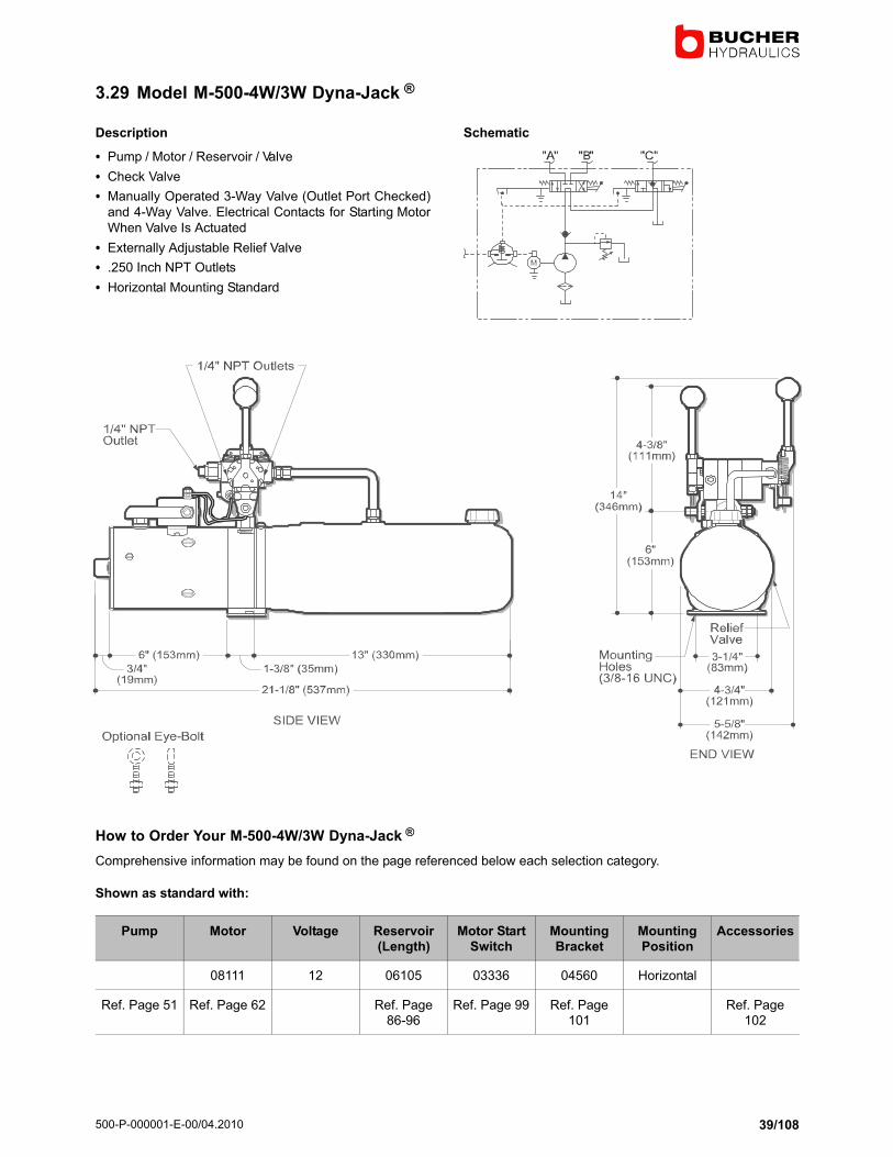
3.29 Model M−500−4W/3W Dyna−Jack�®
Description
� Pump�/�Motor�/�Reservoir�/�Valve
� Check Valve
� Manually Operated 3−Way Valve (Outlet Port Checked)
and 4−Way Valve. Electrical Contacts for Starting Motor
When Valve Is Actuated
� Externally Adjustable Relief Valve
� .250 Inch NPT Outlets
� Horizontal Mounting Standard
Schematic
How to Order Your M−500−4W/3W Dyna−Jack�®
Comprehensive information may be found on the page referenced below each selection category.
Shown as standard with:
Pump Motor Voltage Reservoir(Length)
Motor StartSwitch
MountingBracket
MountingPosition
Accessories
08111 12 06105 03336 04560 Horizontal
Ref. Page 51 Ref. Page 62 Ref. Page86−96
Ref. Page 99 Ref. Page101
Ref. Page102

500−P−000001−E−00/04.2010
40/108
3.30 Model M−683 Dyna Ramic ®
Description
� Pump�/�Motor�/�Reservoir�/�Valve
� Check Valve
� 1 4−Way/2−Position and 3 x 2−Way/2−Position N.C. Sole-
noid Cartridge Valves Located Inside Reservoir provide
4W/3W Function
� All Ports Filtered
� By−Pass (Also Referred to as Cross−Over) Relief Valves
Are Located Between C1 and C2 Ports
� Cord with Connector Plug
� Externally Adjustable Relief Valve
� .250 Inch NPT Outlets
� Horizontal Mounting Standard
Popular Options
� Control Box
� Vertical Mounting�/�Motor Up
Typical Application
� Snow Plow. Up. Down. Float; Left. Right
Schematic
How to Order Your M−683 Dyna Ramic ®
Comprehensive information may be found on the page referenced below each selection category.
Shown as standard with:
Pump Motor Voltage Reservoir(Length)
Motor StartSwitch
ControlBoxes
MountingBracket
MountingPosition
Accesso-ries
08111 12 06703 17757 03197 02238 Horizontal
Ref. Page51
Ref. Page62
Ref. Page86−96
Ref. Page99
Ref. Page100
Ref. Page101
Ref. Page102
500−P−000001−E−00/04.2010
41/108
3.31 Model M−3528 Dyna−Jack�®
Description
� Pump�/�Motor�/�Reservoir�/�Valve
� Check Valve in "P" Port
� Externally Adjustable Relief Valve
� 2 x D03 Solenoid Valve
� #6 SAE Outlet
� Horizontal Mounting Standard
Popular Options
� Control Box and Cord
� Vertical Mounting�/�Motor Up
� Large Selection of D03/CETOP Valves and Accessories
Schematic
How to Order Your M−3528 Dyna−Jack�®
Comprehensive information may be found on the page referenced below each selection category.
Shown as standard with:
Pump Motor Voltage Reservoir(Length)
Motor StartSwitch
MountingPosition
Accessories Control Bo-xes
08111 12 06102 17757 Horizontal
Ref. Page 51 Ref. Page 62 Ref. Page86−96
Ref. Page 99 Ref. Page102
Ref. Page100

500−P−000001−E−00/04.2010
42/108
3.32 Model M−3529 Dyna−Jack�®
Description
� Pump / Motor / Reservoir / Manifold
� Check Valve in "P" Port
� Externally Adjustable Relief Valve
� #6 SAE Outlet
� Horizontal Mounting Standard
Popular Options
� Control Box and Cord
� Vertical Mounting�/�Motor Up
� Large Selection of D03/CETOP Valves and Accessories
Schematic
How to Order Your M−3529 Dyna−Jack�®
Comprehensive information may be found on the page referenced below each selection category.
Shown as standard with:
Pump Motor Voltage Reservoir(Length)
Motor StartSwitch
MountingPosition
Accessories Control Bo-xes
08111 12 06102 17757 Horizontal
Ref. Page 51 Ref. Page 62 Ref. Page86−96
Ref. Page 99 Ref. Page102
Ref. Page100

500−P−000001−E−00/04.2010
43/108
3.33 Model M−3593 Dyna−Jack�®
Description
� Pump�/�Motor�/�Reservoir�/�Valve
� Externally Adjustable Relief Valve
� Solenoid Cartridge Valves, Pilot Operated Check Valves
and Adjustable Cross−Over Relief System Mounted In a
Compact Manifold
� Ideal System For Operating a Snow Plow. Power Up,
Hold, Gravity Down, Left, Right
� Horizontal Mounting Standard
Popular Options
� Control Box and Cord
� Vertical Mounting�/�Motor Up
Schematic
How to Order Your M−3593 Dyna−Jack�®
Comprehensive information may be found on the page referenced below each selection category.
Shown as standard with:
Pump Motor Voltage Reservoir(Length)
Motor StartSwitch
MountingPosition
Accessories Control Bo-xes
08111 12 06102 17757 Horizontal
Ref. Page 51 Ref. Page 62 Ref. Page86−96
Ref. Page 99 Ref. Page102
Ref. Page100

500−P−000001−E−00/04.2010
44/108
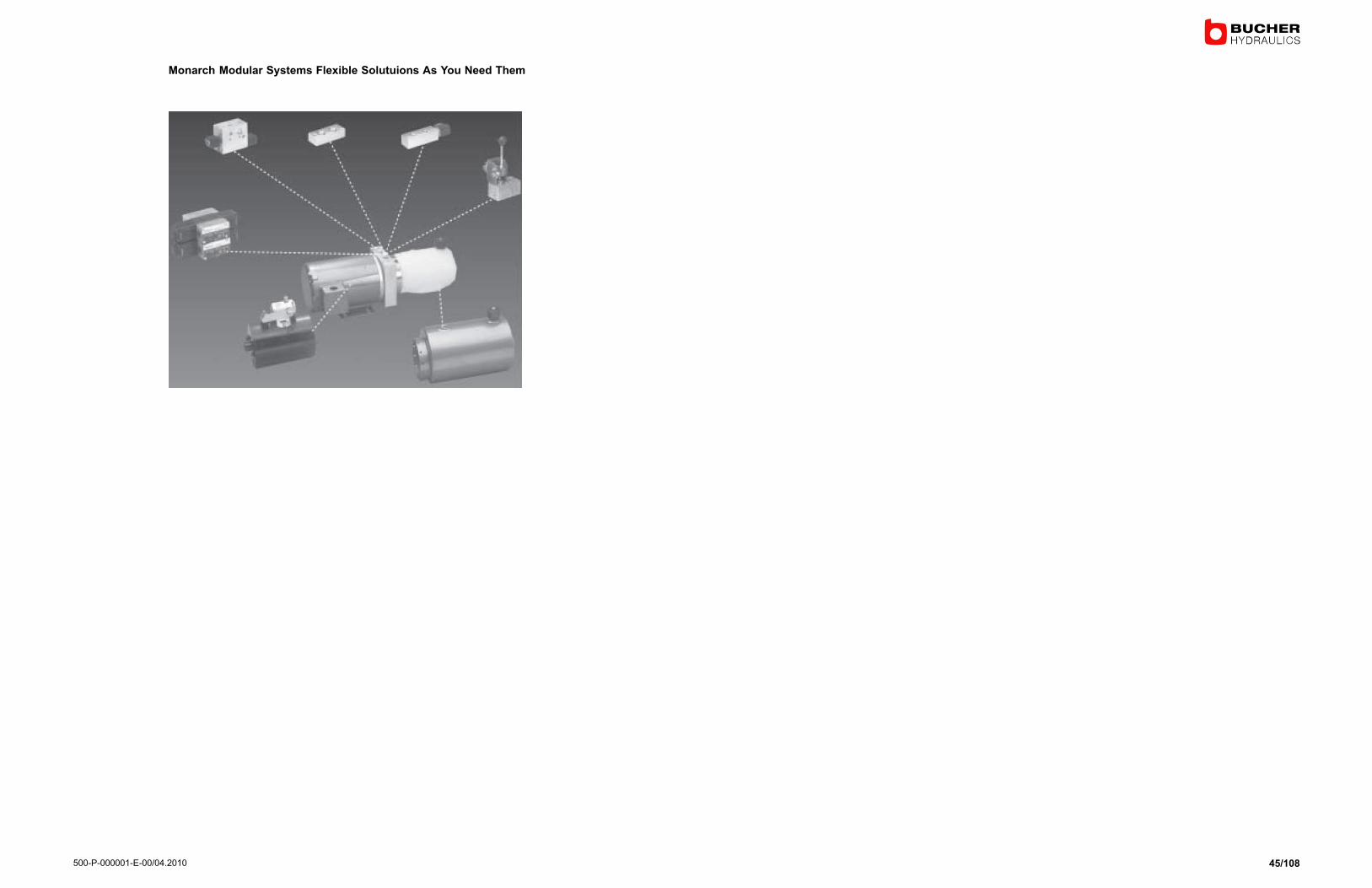
3.34 Modular Power Units
Description
� Add Standard or Custom Manifolds to a Basic M−3598
Power Unit with "P" and "T" Ports.
� Modular Manifolds Mount to Standard Pad. Allow for a
Building Block Approach to Power Unit Flexibility and Cir-
cuit Design.
� For Use With All Monarch Pumps, Motors, and Reser-voirs. Note − A spacer may be required with certain reser-
voirs, on others the valve package may cover reservoir fill
and return ports − consult factory.
Schematic
500−P−000001−E−00/04.2010
45/108
Monarch Modular Systems Flexible Solutuions As You Need Them

500−P−000001−E−00/04.2010
46/108
Add Any Of The Following Circuits To The M−3598 Power unit

500−P−000001−E−00/04.2010
47/108
3.35 How to Order Your Modular Power Unit
Select from the following options. Comprehensive information may be found on the page referenced below each selection category.
Model M−
SelectModel
Pump Motor Voltage Reservoir(Length)
ControlBoxes
Motor StartSwitch
MountingBracket
MountingPosition
Ref. Page Ref. Page51
Ref. Page62
Ref. Page86−96
Ref. Page100
Ref. Page99
Ref. Page101
M−3598 17−150 08053 12 4.5x8 07793 17757 Optional Horizontal
M−3504 17−190 08111 12 4.5x10 07795 17744 02238
M−3513 17−270 08058 12 4.5x12 SpecifyCord
Lenght
Inches
17744 01289 Vertical
M−3519 13−150 08058 12 4.5x13 Start Switchto MotorCable
M−3515 13−200 Bus Bar
M−3528 13−250 6x9
M−3542 13−200 6x10
M−3552 13−380 6x13.5
M−3530 08196 12 6x8
M−3547 08050 12
M−3593 08163 12 5.5x6.5x10
08051 24 5.5x6.5x13.5
08120 24 5.5x6.5x19
08035 24 6.25x7x7
08055 36 6.25x7x7
08168 36 6.25x7x12
08055 48 6.25x7x15
08174 72 6.25x7x15
6.25x7x21
*Max Flow
= 2.75 GPM

500−P−000001−E−00/04.2010
48/108
3.36 S−326 Pump/Motor Units
S−326 Units Feature SAE AA and SAE A Pumps and Permanent Magnet Motors.
Permanent magnet motors are typically uesd to operate hydraulic equipment for material handling devices, aerial platforms,
and emergency back−up systems because they provide extended run times and linear pump outputs at various pressures
for smooth operation. Pressure loaded pumps deliver high volumetric efficiency and are fitted with spline shafts for optimumengagement with the motor drive shaft.
Please select a motor and pump combination from the following chart and performance curves. Motor thermal data (run time)
may be found on page 86.
PartNumber
Voltage Pump Interface
InsulationClass
DimensionPage
Perfor-manceCurve
Numberof Termi-
nals
Frame UL Listed
Descrip-tion
*See Key
08164 12 SAE AA1/2" Spline
F 45.0 AA 2 48(5.6" ø)
No OFC
08166 24 SAE AA1/2" Spline
F 45.0 AB 2 48(5.6" ø)
No OFC
08167 24 SAE A5/8" Spline
F 45.0 AD 2 48(5.6" ø)
No OFC
08169 36 SAE AA1/2" Spline
F 45.0 AF 2 48(5.6" ø)
No OFC
08170 36 SAE A5/8" Spline
F 45.0 AG 2 48(5.6" ø)
No OFC
08171 48 SAE AA1/2" Spline
F 45.0 AH 2 48(5.6" ø)
No OFC
08172 48 SAE AA5/8" Spline
F 45.0 AI 2 48(5.6" ø)
No OFC
08175 72 SAE AA1/2" Spline
F 45.0 AJ 2 48(5.6" ø)
No OFC
08176 72 SAE A5/8" Spline
F 45.0 AK 2 48(5.6" ø)
No OFC
08734 BAND KIT 45.0
*Abbreviation Key:OFC = Open Fan Cooled
A band kit is available that will convert the motor from OFC to EFC (Enclosed Fan Cooled). Use of the bandreduces thermal performance. Please contact the factory for more information.
Specifications, descriptions, and illustrative material contained herein were as accurate as known at the time this publication was
approved for printing. Bucher Hydraulics, Inc. reserves the right to discontinue models at any time or change specifications without
notice or incurring obligation.

500−P−000001−E−00/04.2010
49/108
3.37 Dimensional Information for S−326 Pump/Motor Units
End View and Side View of Motor with SAE AA Pump
End View and Side View of Motor with SAE A Pump
View of Mounting Plate

500−P−000001−E−00/04.2010
50/108
3.38 SAE AA Pump Data
Pump Code DISPLACEMENT In3/Rev
"A" DIMENSION(Inches)
1.4 0.081 3.23
2.1 0.126 3.23
2.8 0.166 3.23
3.5 0.200 3.46
4.1 0.248 3.46
5.2 0.317 3.70
6.1 0.369 3.70
3.39 SAE A Pump Data
Pump Code DISPLACEMENT In3/Rev
"A" DIMENSION(Inches)
4.5 0.27 1.83
6.2 0.37 1.83
8.3 0.50 2.05
3.40 How to Order S−326 Pump/Motor Units
Please select from the following options:
MODEL S−326−
SAE PUMP SIZE PUMP CODE MOTOR VOLTAGE
AA 1.4 08164 12
2.1 08166 24
2.8 08169 36
3.5 08171 48
4.1 08175 72
5.2
6.1
A 4.5 08167 24
6.2 08170 36
8.3 08172 48
08176 72
Example: S−326−AA−2.8−08166−24 is an SAE AA 2.8 Pump (0.166 in3/rev) attached to a 24V D. C. Permanent Magnet Motor.
500−P−000001−E−00/04.2010
51/108
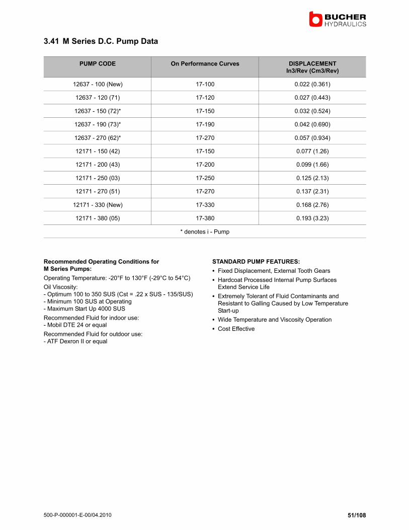
3.41 M Series D.C. Pump Data
PUMP CODE On Performance Curves DISPLACEMENTIn3/Rev (Cm3/Rev)
12637 − 100 (New) 17−100 0.022 (0.361)
12637 − 120 (71) 17−120 0.027 (0.443)
12637 − 150 (72)* 17−150 0.032 (0.524)
12637 − 190 (73)* 17−190 0.042 (0.690)
12637 − 270 (62)* 17−270 0.057 (0.934)
12171 − 150 (42) 17−150 0.077 (1.26)
12171 − 200 (43) 17−200 0.099 (1.66)
12171 − 250 (03) 17−250 0.125 (2.13)
12171 − 270 (51) 17−270 0.137 (2.31)
12171 − 330 (New) 17−330 0.168 (2.76)
12171 − 380 (05) 17−380 0.193 (3.23)
* denotes i − Pump
Recommended Operating Conditions for
M Series Pumps:
Operating Temperature: −20°F to 130°F (−29°C to 54°C)
Oil Viscosity:
− Optimum 100 to 350 SUS (Cst = .22 x SUS − 135/SUS)
− Minimum 100 SUS at Operating
− Maximum Start Up 4000 SUS
Recommended Fluid for indoor use:− Mobil DTE 24 or equal
Recommended Fluid for outdoor use:
− ATF Dexron II or equal
STANDARD PUMP FEATURES:
� Fixed Displacement, External Tooth Gears
� Hardcoat Processed Internal Pump SurfacesExtend Service Life
� Extremely Tolerant of Fluid Contaminants and
Resistant to Galling Caused by Low Temperature
Start−up
� Wide Temperature and Viscosity Operation
� Cost Effective

500−P−000001−E−00/04.2010
52/108
12 Volt D.C. Performance Curves Voltage = 12.3 − AMP� 7043
� Test Fluid = Mobil D.T.E. 24@ 100°F (SUS 160) 34°C (CST 34)
3.42 Performance Curve AA SAE AA Pumps
24 Volt D.C. Performance Curves Voltage = 25.2 − AMP� 4010
� Test Fluid = Mobil D.T.E. 24@ 100°F (SUS 160) 34°C (CST 34)
3.43 Performance Curve AB SAE AA Pumps
500−P−000001−E−00/04.2010
53/108
24 Volt D.C. Performance Curves Voltage = 25.2 − AMP� 4010
� Test Fluid = Mobil D.T.E. 24@ 100°F (SUS 160) 34°C (CST 34)
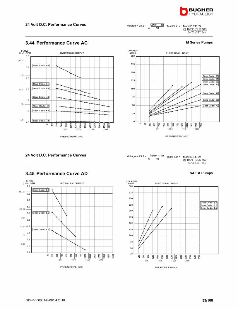
3.44 Performance Curve AC M Series Pumps
24 Volt D.C. Performance Curves Voltage = 25.2 − AMP� 4010
� Test Fluid = Mobil D.T.E. 24@ 100°F (SUS 160) 34°C (CST 34)
3.45 Performance Curve AD SAE A Pumps
500−P−000001−E−00/04.2010
54/108
36 Volt D.C. Performance Curves Voltage = 36.5 − .03 x AMPS Test Fluid = Mobil D.T.E. 24@ 100°F (SUS 160) 34°C (CST 34)
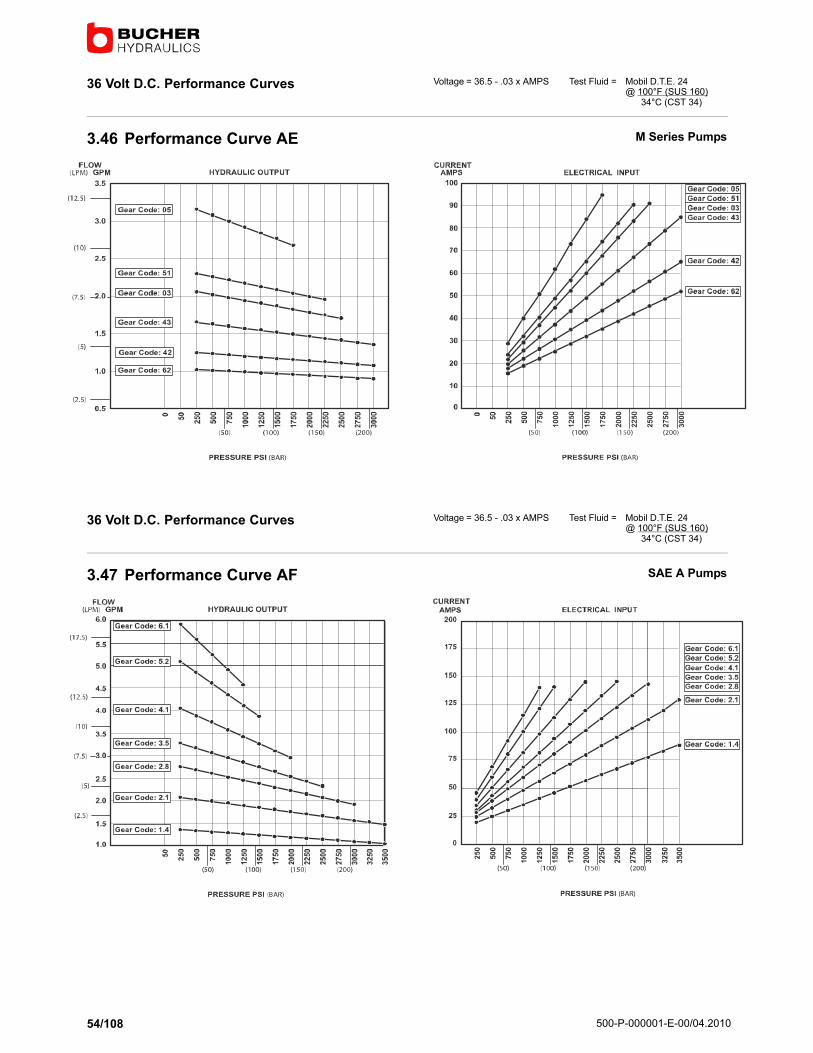
3.46 Performance Curve AE M Series Pumps
36 Volt D.C. Performance Curves Voltage = 36.5 − .03 x AMPS Test Fluid = Mobil D.T.E. 24@ 100°F (SUS 160) 34°C (CST 34)
3.47 Performance Curve AF SAE A Pumps

500−P−000001−E−00/04.2010
55/108
36 Volt D.C. Performance Curves Voltage = 36.5 − .03 x AMPS Test Fluid = Mobil D.T.E. 24@ 100°F (SUS 160) 34°C (CST 34)
3.48 Performance Curve AG SAE A Pumps
48 Volt D.C. Performance Curves Voltage = 48.5 − .03 x AMPS Test Fluid = Mobil D.T.E. 24@ 100°F (SUS 160) 34°C (CST 34)
3.49 Performance Curve AH SAE AA Pumps

500−P−000001−E−00/04.2010
56/108
48 Volt D.C. Performance Curves Voltage = 48.5 − .03 x AMPS Test Fluid = Mobil D.T.E. 24@ 100°F (SUS 160) 34°C (CST 34)
3.50 Performance Curve AI SAE A Pumps
72 Volt D.C. Performance Curves Voltage = 72.4 − .03 x AMPS Test Fluid = Mobil D.T.E. 24@ 100°F (SUS 160) 34°C (CST 34)
3.51 Performance Curve AJ SAE AA Pumps

500−P−000001−E−00/04.2010
57/108
72 Volt D.C. Performance Curves Voltage = 72.4 − .03 x AMPS Test Fluid = Mobil D.T.E. 24@ 100°F (SUS 160) 34°C (CST 34)
3.52 Performance Curve AK SAE A Pumps

500−P−000001−E−00/04.2010
58/108
4 Birotational Hydraulic Power Systems
4.1 Birotational i − Pump
Bi−Rotational i − Pump Data
Pump Number �A" Displacement(in3/R ev)
Displacement(cc/Rev)
Flow @ 1800 rpm(GPM)
12818−100 .100 0.022 0.36 0.17
12818−120 .120 0.027 0.44 0.21
12818−120 .150 0.032 0.52 0.25

500−P−000001−E−00/04.2010
59/108
4.2 Model M−3504
Description
� Birotational Pump and Motor / Reservoir
� Check Valve
� Externally Adjustable Relief Valve
� #6 SAE Outlet
� Horizontal Mounting
Popular Options
� Check Valve in C1 and C2 Ports for Optional Manifold
� Vertical Mounting
Schematic
Consult factory for additional options and specifications.

500−P−000001−E−00/04.2010
60/108
4.3 Model M−3530
Description
� Birotational Pump and Motor / Reservoir
� Check Valve
� Pilot−Operated Check Valves
� Externally Adjustable Relief Valve
� #6 SAE Outlet
� Horizontal Mounting
Popular Options
� Pressure Compensated Flow Controls
� Vertical Mounting
Schematic
Consult factory for additional options and specifications.

500−P−000001−E−00/04.2010
61/108
4.4 Model M−3547
Description
� Birotational Pump and Motor / Reservoir
� 2 x 2−Way/2 Position Solenoid Controlled Cartridge
Valves Located Externally and Manifolded Directly toUnit.
� Check Valve
� Externally Adjustable Relief Valve
� #6 SAE Outlet
� Horizontal Mounting
Popular Options
� Pressure Compensated Flow Controls
� Vertical Mounting
Schematic
Consult factory for additional options and specifications.

500−P−000001−E−00/04.2010
62/108
5 Dim. Information for Standard D.C. Motors with Performance Curves
5.1 M Series D.C. Motor Information
Part Number Voltage InsulationClass
DimensionsPage
Number ofTerminals
Housing DiameterInch (mm)
UL Listed Description*See Key
08053 12 A 63 1 3" (77mm) NO PM/ID
08111 12 B 64 1 4.5" (115mm) NO SM/ID
08058 12 B 65 1 4.5" (115mm) NO SW/IDBall Bearing
Commuta to r
E nd
18442 12 B 66 2 4.5" (115mm) NO SW/ID
08196 12 B 67 1 4.5" (115mm) NO SW/ID
08050 12 H 68 2 5.5" (140mm) NO SW/ID
08163 12 H 69 2 4.6" (117mm) YES PM/ID
08164 12 H 70 2 5.75" (146mm) YES PM/ID
08045 12 B 71 1 4.5" (115mm) NO SM/ID
08003 12 B 1 4.5" (115mm) NO SW/HD
08030 24 B 72 2 4.5" (115mm) NO SW/ID
08004 12 F 73 1 3.25" (83mm) NO PM/ID
08189 12 F 74 1 3.7" (??mm) NO SW/ID
08051 24 A 76 2 3" (77mm) YES PM/ID
08120 24 B 77 2 4.5" (115mm) YES SW/ID
08035 24 H 78 2 5.4" (??mm) YES PM/ID
08066 12 H 75 2 5.5" (140mm) NO SW/ID
08195 24 F 79 1 3.25" (83mm) NO PM/ID
08168 36 H 80 2 5" (117mm) YES PM/ID
08055 36/48 B 81 2 4.5" (115mm) NO SW/ID
08040 48 H 82 2 5" (117mm) YES PM/ID
08055 48/36 B 81 2 4.5" (115mm) NO SW/ID
08174 72/80 H 84 2 5" (117mm) YES PM/ID
∗ Key to Abbreviations:
PM = Permanent Magnet SW = Series Wound ED = Extended Duty HD = Heavy DutyID = Intermittent Duty CW = Compound Wound
A Thermal Protection Switch is available as an option on most motors and must be used with solenoid motor start switch. Formotor thermal performance data, refer to the thermal chart on page ??
500−P−000001−E−00/04.2010
63/108
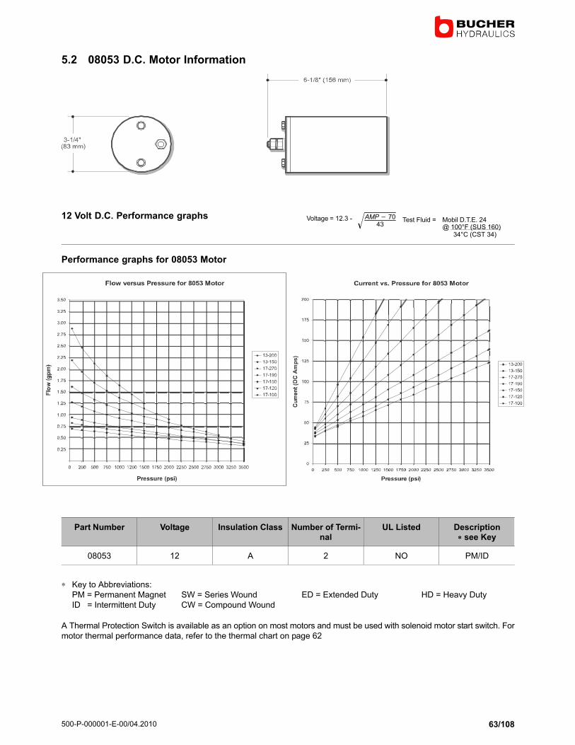
5.2 08053 D.C. Motor Information
12 Volt D.C. Performance graphs Voltage = 12.3 − AMP� 7043
� Test Fluid = Mobil D.T.E. 24@ 100°F (SUS 160) 34°C (CST 34)
Performance graphs for 08053 Motor
Part Number Voltage Insulation Class Number of Termi-nal
UL Listed Description� see Key
08053 12 A 2 NO PM/ID
∗ Key to Abbreviations:
PM = Permanent Magnet SW = Series Wound ED = Extended Duty HD = Heavy Duty
ID = Intermittent Duty CW = Compound Wound
A Thermal Protection Switch is available as an option on most motors and must be used with solenoid motor start switch. For
motor thermal performance data, refer to the thermal chart on page 62

500−P−000001−E−00/04.2010
64/108
5.3 08111 D.C. Motor Information
12 Volt D.C. Performance graphs Voltage = 12.3 − AMP� 7043
� Test Fluid = Mobil D.T.E. 24@ 100°F (SUS 160) 34°C (CST 34)
Performance graphs for 08111 Motor
Part Number Voltage Insulation Class Number of Termi-nal
UL Listed Description� see Key
08111 12 B 1 NO SW/ID
∗ Key to Abbreviations:
PM = Permanent Magnet SW = Series Wound ED = Extended Duty HD = Heavy Duty
ID = Intermittent Duty CW = Compound Wound
A Thermal Protection Switch is available as an option on most motors and must be used with solenoid motor start switch. For
motor thermal performance data, refer to the thermal chart on page 62

500−P−000001−E−00/04.2010
65/108
5.4 08058 D.C. Motor Information
12 Volt D.C. Performance graphs Voltage = 12.3 − AMP� 7043
� Test Fluid = Mobil D.T.E. 24@ 100°F (SUS 160) 34°C (CST 34)
Performance graphs for 08058 Motor
Part Number Voltage Insulation Class Number of Termi-nal
UL Listed Description� see Key
08058 12 B 1 NO SW/ID
∗ Key to Abbreviations:
PM = Permanent Magnet SW = Series Wound ED = Extended Duty HD = Heavy Duty
ID = Intermittent Duty CW = Compound Wound
A Thermal Protection Switch is available as an option on most motors and must be used with solenoid motor start switch. For
motor thermal performance data, refer to the thermal chart on page 62

500−P−000001−E−00/04.2010
66/108
5.5 18442 D.C. Motor Information
12 Volt D.C. Performance graphs Voltage = 12.3 − AMP� 7043
� Test Fluid = Mobil D.T.E. 24@ 100°F (SUS 160) 34°C (CST 34)
Performance graphs for 18442 Motor
Part Number Voltage Insulation Class Number of Termi-nal
UL Listed Description� see Key
18442 12 B 2 YES SW/ID
∗ Key to Abbreviations:
PM = Permanent Magnet SW = Series Wound ED = Extended Duty HD = Heavy Duty
ID = Intermittent Duty CW = Compound Wound
A Thermal Protection Switch is available as an option on most motors and must be used with solenoid motor start switch. For
motor thermal performance data, refer to the thermal chart on page 62

500−P−000001−E−00/04.2010
67/108
5.6 08196 D.C. Motor Information (Replaces 08100)
12 Volt D.C. Performance graphs Voltage = 12.3 − AMP� 7043
� Test Fluid = Mobil D.T.E. 24@ 100°F (SUS 160) 34°C (CST 34)
Performance graphs for 08196 Motor
Part Number Voltage Insulation Class Number of Termi-nal
UL Listed Description� see Key
08196 12 B 1 NO SW/HD
∗ Key to Abbreviations:
PM = Permanent Magnet SW = Series Wound ED = Extended Duty HD = Heavy Duty
ID = Intermittent Duty CW = Compound Wound
A Thermal Protection Switch is available as an option on most motors and must be used with solenoid motor start switch. For
motor thermal performance data, refer to the thermal chart on page 62

500−P−000001−E−00/04.2010
68/108
5.7 08050 D.C. Motor Information
12 Volt D.C. Performance graphs Voltage = 12.3 − AMP� 7043
� Test Fluid = Mobil D.T.E. 24@ 100°F (SUS 160) 34°C (CST 34)
Performance graphs for 08050 Motor
Part Number Voltage Insulation Class Number of Termi-nal
UL Listed Description� see Key
08050 12 H 2 YES SW/ED
∗ Key to Abbreviations:
PM = Permanent Magnet SW = Series Wound ED = Extended Duty HD = Heavy Duty
ID = Intermittent Duty CW = Compound Wound
A Thermal Protection Switch is available as an option on most motors and must be used with solenoid motor start switch. For
motor thermal performance data, refer to the thermal chart on page 62

500−P−000001−E−00/04.2010
69/108
5.8 08163 D.C. Motor Information
12 Volt D.C. Performance graphs Voltage = 12.3 − AMP� 7043
� Test Fluid = Mobil D.T.E. 24@ 100°F (SUS 160) 34°C (CST 34)
Performance graphs for 08163 Motor
Part Number Voltage Insulation Class Number of Termi-nal
UL Listed Description� see Key
08163 12 H 2 NO PM/ID
∗ Key to Abbreviations:
PM = Permanent Magnet SW = Series Wound ED = Extended Duty HD = Heavy Duty
ID = Intermittent Duty CW = Compound Wound
A Thermal Protection Switch is available as an option on most motors and must be used with solenoid motor start switch. For
motor thermal performance data, refer to the thermal chart on page 62

500−P−000001−E−00/04.2010
70/108
5.9 08164 D.C. Motor Information
12 Volt D.C. Performance graphs Voltage = 12.3 − AMP� 7043
� Test Fluid = Mobil D.T.E. 24@ 100°F (SUS 160) 34°C (CST 34)
Performance graphs for 08164 Motor
Part Number Voltage Insulation Class Number of Termi-nal
UL Listed Description� see Key
08164 12 H 2 NO PM/ID
∗ Key to Abbreviations:
PM = Permanent Magnet SW = Series Wound ED = Extended Duty HD = Heavy Duty
ID = Intermittent Duty CW = Compound Wound
A Thermal Protection Switch is available as an option on most motors and must be used with solenoid motor start switch. For
motor thermal performance data, refer to the thermal chart on page 62

500−P−000001−E−00/04.2010
71/108
5.10 08045 D.C. Motor Information
12 Volt D.C. Performance graphs Voltage = 12.3 − AMP� 7043
� Test Fluid = Mobil D.T.E. 24@ 100°F (SUS 160) 34°C (CST 34)
Performance graphs for 08045 Motor
Part Number Voltage Insulation Class Number of Termi-nal
UL Listed Description� see Key
08045 12 B 1 NO SW/ID
∗ Key to Abbreviations:
PM = Permanent Magnet SW = Series Wound ED = Extended Duty HD = Heavy Duty
ID = Intermittent Duty CW = Compound Wound
A Thermal Protection Switch is available as an option on most motors and must be used with solenoid motor start switch. For
motor thermal performance data, refer to the thermal chart on page 62

500−P−000001−E−00/04.2010
72/108
5.11 08030 D.C. Motor Information
24 Volt D.C. Performance graphs Voltage = 12.3 − AMP� 7043
� Test Fluid = Mobil D.T.E. 24@ 100°F (SUS 160) 34°C (CST 34)
Performance graphs for 08030 Motor
Part Number Voltage Insulation Class Number of Termi-nal
UL Listed Description� see Key
08030 24 B 2 NO SW/ID
∗ Key to Abbreviations:
PM = Permanent Magnet SW = Series Wound ED = Extended Duty HD = Heavy Duty
ID = Intermittent Duty CW = Compound Wound
A Thermal Protection Switch is available as an option on most motors and must be used with solenoid motor start switch. For
motor thermal performance data, refer to the thermal chart on page 62

500−P−000001−E−00/04.2010
73/108
5.12 08004 D.C. Motor Information
12 Volt D.C. Performance graphs Voltage = 12.3 − AMP� 7043
� Test Fluid = Mobil D.T.E. 24@ 100°F (SUS 160) 34°C (CST 34)
Performance graphs for 08004 Motor
Part Number Voltage Insulation Class Number of Termi-nal
UL Listed Description� see Key
08004 12 F 1 NO PM/ID
∗ Key to Abbreviations:
PM = Permanent Magnet SW = Series Wound ED = Extended Duty HD = Heavy Duty
ID = Intermittent Duty CW = Compound Wound
A Thermal Protection Switch is available as an option on most motors and must be used with solenoid motor start switch. For
motor thermal performance data, refer to the thermal chart on page 62

500−P−000001−E−00/04.2010
74/108
5.13 08189 D.C. Motor Information
12 Volt D.C. Performance graphs Voltage = 12.3 − AMP� 7043
� Test Fluid = Mobil D.T.E. 24@ 100°F (SUS 160) 34°C (CST 34)
Performance graphs for 08189 Motor
Part Number Voltage Insulation Class Number of Termi-nal
UL Listed Description� see Key
08189 12 F 1 NO SW/ID
∗ Key to Abbreviations:
PM = Permanent Magnet SW = Series Wound ED = Extended Duty HD = Heavy Duty
ID = Intermittent Duty CW = Compound Wound
A Thermal Protection Switch is available as an option on most motors and must be used with solenoid motor start switch. For
motor thermal performance data, refer to the thermal chart on page 62

500−P−000001−E−00/04.2010
75/108
5.14 08066 D.C. Motor Information
12 Volt D.C. Performance graphs Voltage = 25.2 − AMP� 4010
� Test Fluid = Mobil D.T.E. 24@ 100°F (SUS 160) 34°C (CST 34)
Performance graphs for 08066 Motor
Part Number Voltage Insulation Class Number of Termi-nal
UL Listed Description� see Key
08066 12 H 2 NO SW/HD
∗ Key to Abbreviations:
PM = Permanent Magnet SW = Series Wound ED = Extended Duty HD = Heavy Duty
ID = Intermittent Duty CW = Compound Wound
A Thermal Protection Switch is available as an option on most motors and must be used with solenoid motor start switch. For
motor thermal performance data, refer to the thermal chart on page 62

500−P−000001−E−00/04.2010
76/108
5.15 08051 D.C. Motor Information
24 Volt D.C. Performance graphs Voltage = 25.2 − AMP� 4010
� Test Fluid = Mobil D.T.E. 24@ 100°F (SUS 160) 34°C (CST 34)
Performance graphs for 08051 Motor
Part Number Voltage Insulation Class Number of Termi-nal
UL Listed Description� see Key
08051 24 A 2 NO PM/ID
∗ Key to Abbreviations:
PM = Permanent Magnet SW = Series Wound ED = Extended Duty HD = Heavy Duty
ID = Intermittent Duty CW = Compound Wound
A Thermal Protection Switch is available as an option on most motors and must be used with solenoid motor start switch. For
motor thermal performance data, refer to the thermal chart on page 62

500−P−000001−E−00/04.2010
77/108
5.16 08120 D.C. Motor Information
24 Volt D.C. Performance graphs Voltage = 25.2 − AMP� 4010
� Test Fluid = Mobil D.T.E. 24@ 100°F (SUS 160) 34°C (CST 34)
Performance graphs for 08120 Motor
Part Number Voltage Insulation Class Number of Termi-nal
UL Listed Description� see Key
08120 24 B 2 YES SW/ID
∗ Key to Abbreviations:
PM = Permanent Magnet SW = Series Wound ED = Extended Duty HD = Heavy Duty
ID = Intermittent Duty CW = Compound Wound
A Thermal Protection Switch is available as an option on most motors and must be used with solenoid motor start switch. For
motor thermal performance data, refer to the thermal chart on page 62

500−P−000001−E−00/04.2010
78/108
5.17 08035 D.C. Motor Information
24 Volt D.C. Performance graphs Voltage = 25.2 − AMP� 4010
� Test Fluid = Mobil D.T.E. 24@ 100°F (SUS 160) 34°C (CST 34)
Performance graphs for 08035 Motor
Part Number Voltage Insulation Class Number of Termi-nal
UL Listed Description� see Key
08035 24 H 2 NO PM/ID
∗ Key to Abbreviations:
PM = Permanent Magnet SW = Series Wound ED = Extended Duty HD = Heavy Duty
ID = Intermittent Duty CW = Compound Wound
A Thermal Protection Switch is available as an option on most motors and must be used with solenoid motor start switch. For
motor thermal performance data, refer to the thermal chart on page 62

500−P−000001−E−00/04.2010
79/108
5.18 08195 D.C. Motor Information
24 Volt D.C. Performance graphs Voltage = 25.2 − AMP� 4010
� Test Fluid = Mobil D.T.E. 24@ 100°F (SUS 160) 34°C (CST 34)
Performance graphs for 08195 Motor
Part Number Voltage Insulation Class Number of Termi-nal
UL Listed Description� see Key
08195 24 F 1 NO PM/ID
∗ Key to Abbreviations:
PM = Permanent Magnet SW = Series Wound ED = Extended Duty HD = Heavy Duty
ID = Intermittent Duty CW = Compound Wound
A Thermal Protection Switch is available as an option on most motors and must be used with solenoid motor start switch. For
motor thermal performance data, refer to the thermal chart on page 62

500−P−000001−E−00/04.2010
80/108
5.19 08168 D.C. Motor Information
36 Volt D.C. Performance graphs Voltage = 36.5 − .03 x AMPSTest Fluid = Mobil D.T.E. 24
@ 100°F (SUS 160) 34°C (CST 34)
Performance graphs for 08168 Motor
Part Number Voltage Insulation Class Number of Termi-nal
UL Listed Description� see Key
08168 36 H 2 NO SW/HD
∗ Key to Abbreviations:
PM = Permanent Magnet SW = Series Wound ED = Extended Duty HD = Heavy Duty
ID = Intermittent Duty CW = Compound Wound
A Thermal Protection Switch is available as an option on most motors and must be used with solenoid motor start switch. For
motor thermal performance data, refer to the thermal chart on page 62
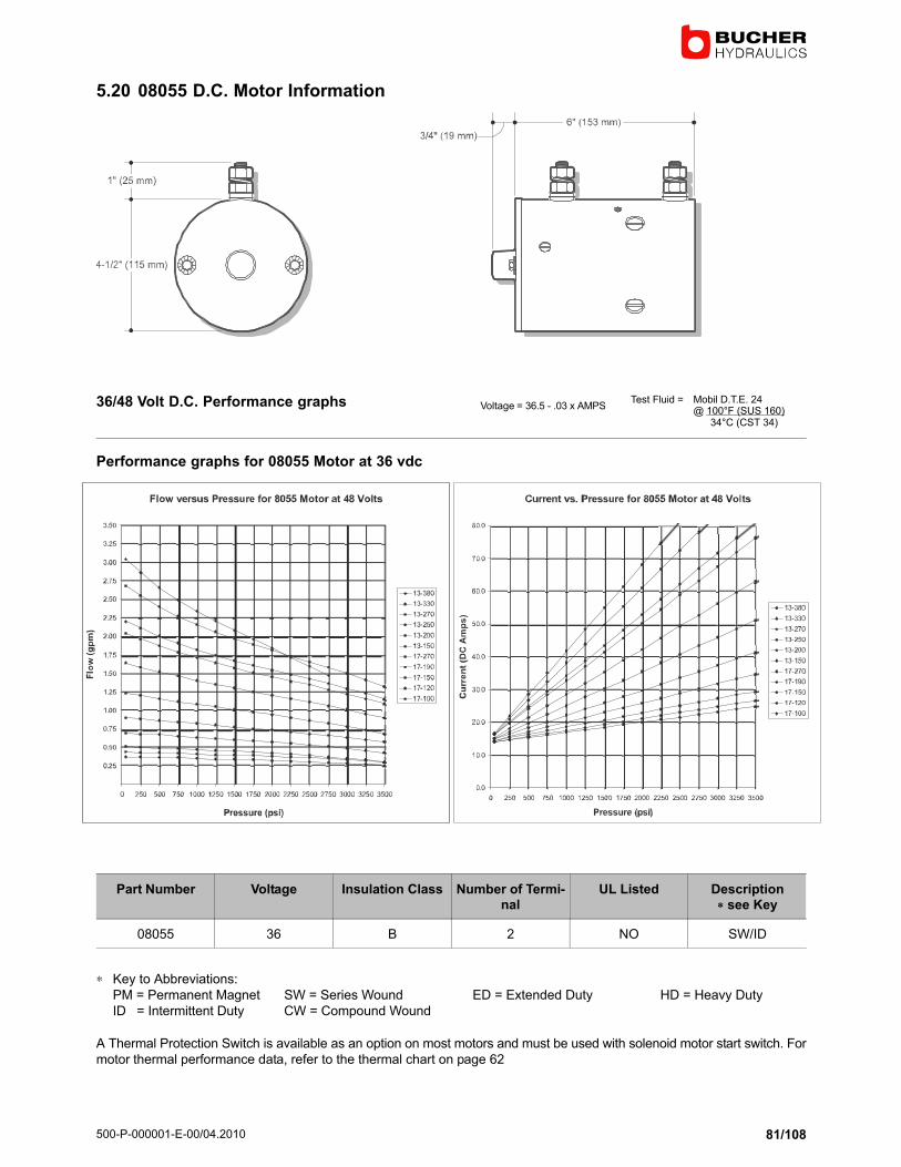
500−P−000001−E−00/04.2010
81/108
5.20 08055 D.C. Motor Information
36/48 Volt D.C. Performance graphs Voltage = 36.5 − .03 x AMPSTest Fluid = Mobil D.T.E. 24
@ 100°F (SUS 160) 34°C (CST 34)
Performance graphs for 08055 Motor at 36 vdc
Part Number Voltage Insulation Class Number of Termi-nal
UL Listed Description� see Key
08055 36 B 2 NO SW/ID
∗ Key to Abbreviations:
PM = Permanent Magnet SW = Series Wound ED = Extended Duty HD = Heavy Duty
ID = Intermittent Duty CW = Compound Wound
A Thermal Protection Switch is available as an option on most motors and must be used with solenoid motor start switch. For
motor thermal performance data, refer to the thermal chart on page 62

500−P−000001−E−00/04.2010
82/108
5.21 08040 D.C. Motor Information
48 Volt D.C. Performance graphs Voltage = 48.5 − .03 x AMPSTest Fluid = Mobil D.T.E. 24
@ 100°F (SUS 160) 34°C (CST 34)
Performance graphs for 08040 Motor
Part Number Voltage Insulation Class Number of Termi-nal
UL Listed Description� see Key
08040 48 H 2 NO PM/ID
∗ Key to Abbreviations:
PM = Permanent Magnet SW = Series Wound ED = Extended Duty HD = Heavy Duty
ID = Intermittent Duty CW = Compound Wound
A Thermal Protection Switch is available as an option on most motors and must be used with solenoid motor start switch. For
motor thermal performance data, refer to the thermal chart on page 62

500−P−000001−E−00/04.2010
83/108
5.22 08055 D.C. Motor Information
36/48 Volt D.C. Performance graphs Voltage = 48.5 − .03 x AMPSTest Fluid = Mobil D.T.E. 24
@ 100°F (SUS 160) 34°C (CST 34)
Performance graphs for 08055 Motor
Part Number Voltage Insulation Class Number of Termi-nal
UL Listed Description� see Key
08055 48 B 2 NO SW/ID
∗ Key to Abbreviations:
PM = Permanent Magnet SW = Series Wound ED = Extended Duty HD = Heavy Duty
ID = Intermittent Duty CW = Compound Wound
A Thermal Protection Switch is available as an option on most motors and must be used with solenoid motor start switch. For
motor thermal performance data, refer to the thermal chart on page 62

500−P−000001−E−00/04.2010
84/108
5.23 08174 D.C. Motor Information
72/80 Volt D.C. Performance graphs Voltage = 72.4 − .03 x AMPSTest Fluid = Mobil D.T.E. 24
@ 100°F (SUS 160) 34°C (CST 34)
Performance graphs for 08174 Motor
Part Number Voltage Insulation Class Number of Termi-nal
UL Listed Description� see Key
08174 72/80 H 2 NO PM/ID
∗ Key to Abbreviations:
PM = Permanent Magnet SW = Series Wound ED = Extended Duty HD = Heavy Duty
ID = Intermittent Duty CW = Compound Wound
A Thermal Protection Switch is available as an option on most motors and must be used with solenoid motor start switch. For
motor thermal performance data, refer to the thermal chart on page 62

500−P−000001−E−00/04.2010
85/108
5.24 Motor Thermal Performance Data
Monarch offers a comprehensive line of D.C. motors that will
operate from light intermittent through extended dutycycles. It is very important to specify the correct motor for
your application.
Most D.C. power units operate intermittently and the thermal
heat rise is negligible. However, climate, duty cycle, enclos-
ure and the ambient working temperature must all be con-sidered for proper motor selection.
The following charts show the average allowable operating-
times for our most popular D.C. motors. Initially, it is recom-
mended that you determine the amperage required at thepeak working pressure of the pump and motor combination
selected and then decide if the motor has the required ther-
mal capacity for your duty cycle. Actual field testing should
be performed to confirm that the motor is thermally ad-
equate.
Key
A = Amps
T = Single Maximum run time allowed in minutes.
Frequently referred to as S2.
%= Maximum allowable run time for a repeating 10*
minutecycle. Frequently referred to as S3. Note. Some motors are rated for a 5 minute cycle and
are so noted on the chart.
* = No data available.
Example: 08111 Motor. At 100 Amps the motor may beoperated continuously for 9.5 minutes after which it must be
allowed to completely cool to ambient temperature before
the cycle can be repeated. Alternatively, at 100 Amps the
motor may be operated for repeating cycles of 150 seconds
on and 450 seconds off.
Thermal protection switches are also available on many
models that will protect motors from overheating. Contact
factory.
86.0

500−P−000001−E−00/04.2010
86/108
6 M Series Reservoirs
6.1 M−Series Reservoirs Steel
Part Number Length in / (mm) Useable Capacity
Horizontal Vertical
Cubic inch (in3) Liter (L) Cubic inch (in3) Liter (L)
06042 9.00 (229 mm) 190 3.10 168 2.75
06043 10.00 (254 mm) 217 3.56 194 3.20
06044 13.50 (343 mm) 292 4.80 285 4.70
06045 18.00 (458 mm) 394 6.45 405 6.65
Part Number Length in / (mm) Useable Capacity
Cubic inch (in3) Liter (L)
06661 8.00 (204 mm) 60 1.00
06663 10.00 (254 mm) 85 1.40
06664 11.00 (280 mm) 98 1.60
06665 12.00 (305 mm) 111 1.80

500−P−000001−E−00/04.2010
87/108
Part Number Length in / (mm) Useable Capacity
Cubic inch (in3) Liter (L)
06861 7.00 (178 mm) 236 3.86
06862 10.00 (254 mm) 348 5.70
06328 12.00 (305 mm) 406 6.65
06864 15.00 (381 mm) 510 8.36
06888 21.00 (534 mm) 715 11.72
Part Number Length in / (mm) Useable Capacity
Cubic inch (in3) Liter (L)
06982 21.00 (533 mm) 1193 19.55
06397 23.00 (584 mm) 1302 21.33
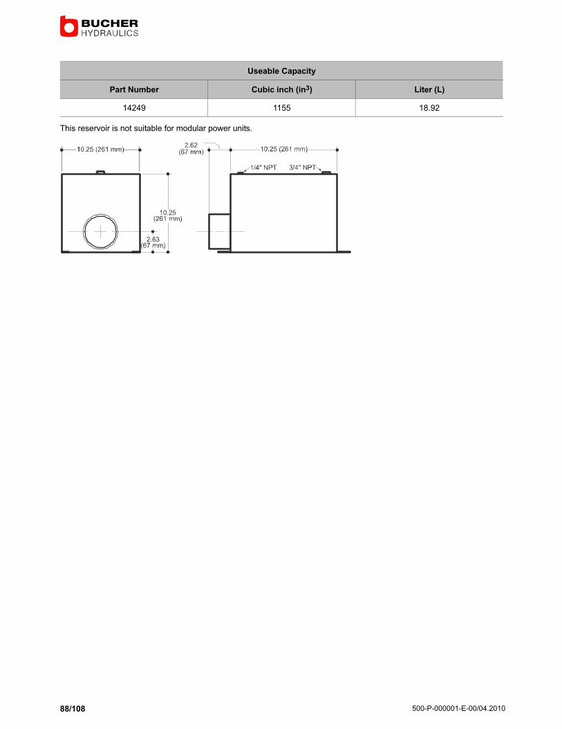
500−P−000001−E−00/04.2010
88/108
Useable Capacity
Part Number Cubic inch (in3) Liter (L)
14249 1155 18.92
This reservoir is not suitable for modular power units.

500−P−000001−E−00/04.2010
89/108
6.2 M−Series Reservoirs Poly
Horizontal Length in / (mm)
Part Number Useable Capacity
Cubic inch (in3) Liter (L)
06102 54.92 0.90 8.00 (203.20)
06103 75.67 1.24 10.00 (254.00)
06104 96.41 1.58 12.00 (304.80)
06105 106.79 1.75 13.00 (330.20)
Vertical Length in / (mm)
Part Number Useable Capacity
Cubic inch (in3) Liter (L)
04616 36.61 0.60 8.00 (203.20)
04617 65.91 1.08 10.00 (254.00)
04618 95.20 1.56 12.00 (304.80)
04619 109.84 1.80 13.00 (330.20)
Useable Capacity may be increased 7.5% with the addition of a suction shroud assembly 13082 When using an I pump, up
to 3% reduction in useable volume should be expected.
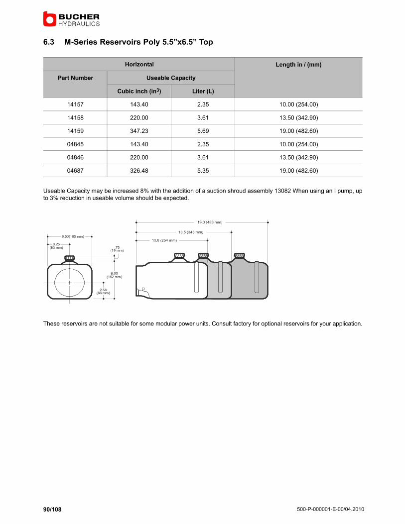
500−P−000001−E−00/04.2010
90/108
6.3 M−Series Reservoirs Poly 5.5˜x6.5˜ Top
Horizontal Length in / (mm)
Part Number Useable Capacity
Cubic inch (in3) Liter (L)
14157 143.40 2.35 10.00 (254.00)
14158 220.00 3.61 13.50 (342.90)
14159 347.23 5.69 19.00 (482.60)
04845 143.40 2.35 10.00 (254.00)
04846 220.00 3.61 13.50 (342.90)
04687 326.48 5.35 19.00 (482.60)
Useable Capacity may be increased 8% with the addition of a suction shroud assembly 13082 When using an I pump, up
to 3% reduction in useable volume should be expected.
These reservoirs are not suitable for some modular power units. Consult factory for optional reservoirs for your application.

500−P−000001−E−00/04.2010
91/108
6.4 M−Series Reservoirs Poly 6˜ Centered
Horizontal Length in / (mm)
Part Number Useable Capacity
Cubic inch (in3) Liter (L)
14128 118.37 1.94 9.00 (228.60)
14121 136.19 2.23 10.00 (254.00)
14122 154.01 2.52 11.00 (279.40)
14123 189.65 3.11 13.00 (330.20)
14124 234.20 3.84 15.50 (393.70)
14125 296.57 4.86 19.00 (482.60)
14126 350.03 5.74 22.00 (558.80)
14127 385.68 6.32 24.00 (609.60)
Vertical Length in / (mm)
Part Number Useable Capacity
Cubic inch (in3) Liter (L)
14004 197.04 3.23 13.00 (330.20)
14005 268.68 4.40 15.50 (393.70)
Useable Capacity may be increased 6% with the addition of a suction shroud assembly 13082 When using an I pump, up
to 3% reduction in useable volume should be expected.
These reservoirs are not suitable for some modular power units. Consult factory for optional reservoirs for your application.

500−P−000001−E−00/04.2010
92/108
6.5 M−Series Reservoirs Poly 6˜ Offset
Horizontal Length in / (mm)
Part Number Useable Capacity
Cubic inch (in3) Liter (L)
14009 123.57 2.03 9.00 (228.60)
14010 143.40 2.35 10.00 (254.00)
14011 163.23 2.68 11.00 (279.40)
14012 202.89 3.33 13.00 (330.20)
14013 252.47 4.14 15.50 (393.70)
14014 321.87 5.28 19.00 (482.60)
14015 381.36 6.25 22.00 (558.80)
14016 421.02 6.90 24.00 (609.60)
Vertical Length in / (mm)
Part Number Useable Capacity
Cubic inch (in3) Liter (L)
14004 88.49 1.45 9.00 (228.60)
14005 112.90 1.85 10.00 (254.00)
14005 137.31 2.25 11.00 (279.40)
14005 186.13 3.05 13.00 (330.20)
14005 247.15 4.05 15.50 (393.70)
14005 332.59 5.45 19.00 (482.60)
14005 405.82 6.65 22.00 (558.80)
14005 454.64 7.45 24.00 (609.60)
Useable Capacity may be increased 6% with the addition of a suction shroud assembly 13082 When using an I pump, up
to 3% reduction in useable volume should be expected.
These reservoirs are not suitable for some modular power units. Consult factory for optional reservoirs for your application.

500−P−000001−E−00/04.2010
93/108
6.6 M−Series Reservoirs Poly 6.75˜x6.75˜
Horizontal Length in / (mm)
Part Number Useable Capacity
Cubic inch (in3) Liter (L)
14164 157.14 2.58 7.50 (190.50)
14165 203.21 3.33 9.00 (228.60)
14166 264.64 4.34 11.00 (279.40)
14167 326.07 5.34 13.00 (330.20)
14168 387.50 6.35 15.00 (381.00)
14169 541.08 8.87 20.00 (508.00)
14170 725.37 11.89 26.00 (660.40)
Vertical Length in / (mm)
Part Number Useable Capacity
Cubic inch (in3) Liter (L)
14183 85.43 1.40 7.50 (190.50)
14184 149.51 2.45 9.00 (228.60)
14185 234.94 3.85 11.00 (279.40)
14186 320.37 5.25 13.00 (330.20)
14187 404.81 6.63 15.00 (381.00)
14188 619.39 10.15 20.00 (508.00)
14189 875.69 14.35 26.00 (660.40)
Useable Capacity may be increased 5% with the addition of a suction shroud assembly 13082 When using an I pump, up
to 3% reduction in useable volume should be expected.
These reservoirs are not suitable for some modular power units. Consult factory for optional reservoirs for your application.

500−P−000001−E−00/04.2010
94/108
6.7 M−Series Reservoirs Poly 9˜x10˜
Horizontal Length in / (mm)
Part Number Useable Capacity
Cubic inch (in3) Liter (L)
14223 909.27 14.90 16.00 (406.40)
14224 1070.00 17.54 18.00 (457.20)
14225 1232.09 20.19 20.00 (508.00)
Vertical Length in / (mm)
Part Number Useable Capacity
Cubic inch (in3) Liter (L)
14226 793.33 13.00 16.00 (406.40)
14227 979.46 16.05 18.00 (457.20)
14228 1165.58 19.10 20.00 (508.00)
Useable Capacity may be increased 5% with the addition of a suction shroud assembly 13082 When using an I pump, up
to 3% reduction in useable volume should be expected.
These reservoirs are not suitable for some modular power units. Consult factory for optional reservoirs for your application.

500−P−000001−E−00/04.2010
95/108
6.8 Reservoirs for Mini Units Poly 3.5"x3.5" MINI
Part Number Horizontal Vertical Length in / (mm)
Useable Capacity
Cubic inch (in3) Liter (L) Cubic inch (in3) Liter (L)
06230 30.51 0.50 24.50 0.40 6.46 (164.08)
06231 62.04 1.02 69.22 1.13 11.08 (281.43)
06233* 125.10 2.05 158.67 2.60 20.32 (516.13)
* Reservoir should not be used in a horizontal application without first consulting engineering (Special supports may be re-
quired).
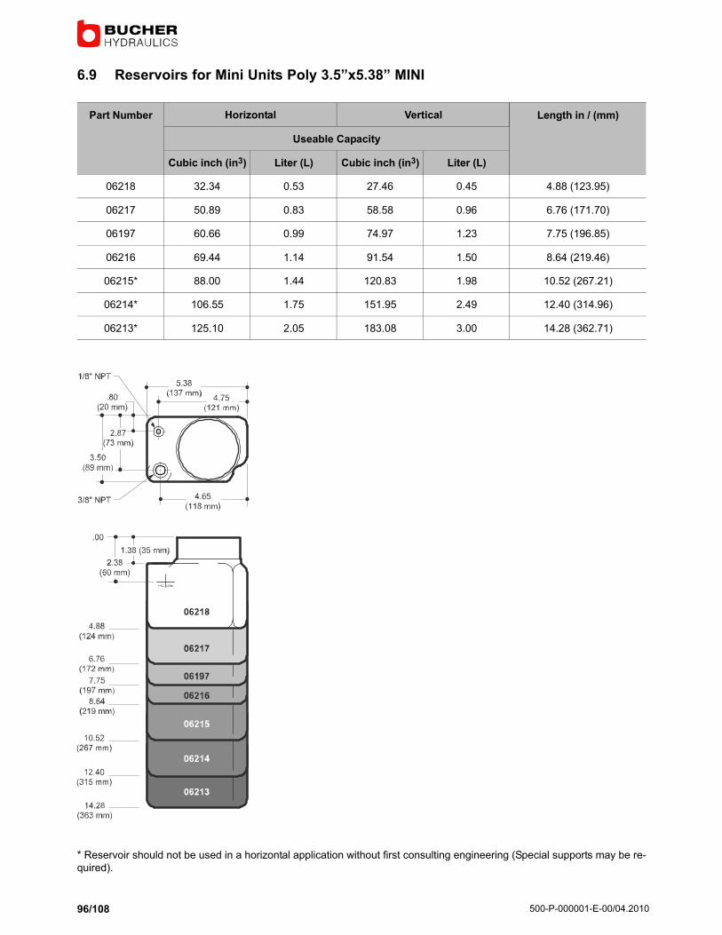
500−P−000001−E−00/04.2010
96/108
6.9 Reservoirs for Mini Units Poly 3.5"x5.38" MINI
Part Number Horizontal Vertical Length in / (mm)
Useable Capacity
Cubic inch (in3) Liter (L) Cubic inch (in3) Liter (L)
06218 32.34 0.53 27.46 0.45 4.88 (123.95)
06217 50.89 0.83 58.58 0.96 6.76 (171.70)
06197 60.66 0.99 74.97 1.23 7.75 (196.85)
06216 69.44 1.14 91.54 1.50 8.64 (219.46)
06215* 88.00 1.44 120.83 1.98 10.52 (267.21)
06214* 106.55 1.75 151.95 2.49 12.40 (314.96)
06213* 125.10 2.05 183.08 3.00 14.28 (362.71)
* Reservoir should not be used in a horizontal application without first consulting engineering (Special supports may be re-
quired).

500−P−000001−E−00/04.2010
97/108
6.10 Valves for DC Systems
NPFA DO3 Directional and Auxiliary Control Valves.
Solenoid directional and auxiliary controls are typically added to the M−3515 and M−3528.Please refer to the Monarch Direc-
tional Control. Valve brochure for additional information and selection.
Part Number Schematic Description
12 VDC − 00962
24 VDC − 00965
A
b a
B
P T
4−Way/3−Position.Solenoid Operated.
Tandem Center.
12 VDC − 00963
24 VDC − 00966
A
b a
B
P T
4−Way/3−Position.Solenoid Operated.
Open Center.
12 VDC − 00961
24 VDC − 00964
A
b a
B
P T
4−Way/3−Position.Solenoid Operated.
Closed Center.
12 VDC − 01040
24 VDC − 01039
A
b a
B
P T
4−Way/3−Position, P Blocked.A and B to T."Motor Spool".
12 VDC − 00460
24 VDC − 00461 b P T
4−Way/2−Position.P to A.
Spring Offset.
12 VDC − 00460
24 VDC − 00461
A
b a
B
P T
4−Way/2−Position.P to A.
Spring Offset.
00468 B1 A1
B AP T
Dual Pilot Operated Check.A and B Port.
00469
A BP T
Flow Control.Dual Meter Out.
A and B Port.
00443
A BP T
Cross Port Relief.A and B Ports.
Adjustable.
00474
A BP T
Dual Relief.A and B Ports to T.
Adjustable.
Consult Bucher Hydraulics about special requirements for explosion proof, shockless (soft shift) and other function and spool
configurations not shown here. Other DC as well as AC voltages are available. Functional symbols related to solenoid identity
"A" or "B" according to NFPA/ANSI standards, i.e., energizing solenoid "A" gives flow P to A, solenoid "B" gives flow P to B(As Applicable).

500−P−000001−E−00/04.2010
98/108
Cartridge Valves
Solenoid operated cartridge valves are used in the M−3319 and various other models.
Part Number Schematic Description
12 VDC − 00707
24 VDC − 07158
IN
OUT
2−Way/2−Position Normally Closed.Modified Cavity #8.
Grounded Coil.
07144 IN
OUT
2−Way/2−Position Normally Closed.Modified Cavity #8. Manual Operation.
Pull to Open. Spring Closed.
12 VDC − 00501
24 VDC − 00502
IN
OUT
2−Way/2−Position Normally Open.Modified Cavity #8.
Grounded Coil.
Consult Factory about many additional valve voltages, coil terminations and other options.
Manual Valves
Manually Operated Directional Control Valves are used on Models M−3310, M−500 and M−300 Special Units.
Part Number Schematic Description
M−3310 Condenser Type − 01020 A B
P T
4−Way/3−Position.Closed Center.
Direct Mounting.
M−500 Type − 00853 CYL 3−Way/3−Position.Cylinder Port Checked.
Direct Mounting.
M−3310 Condenser Type − 00893M−500 Type − 00856
(Non Condenser Type)
A B
P T
4−Way/3−Position.Tandem Center.Direct Mounting.
M−3310 Cam Start SW − 07120 A B
P T
4−Way/3−Position.Tandem Center.Direct Mounting.
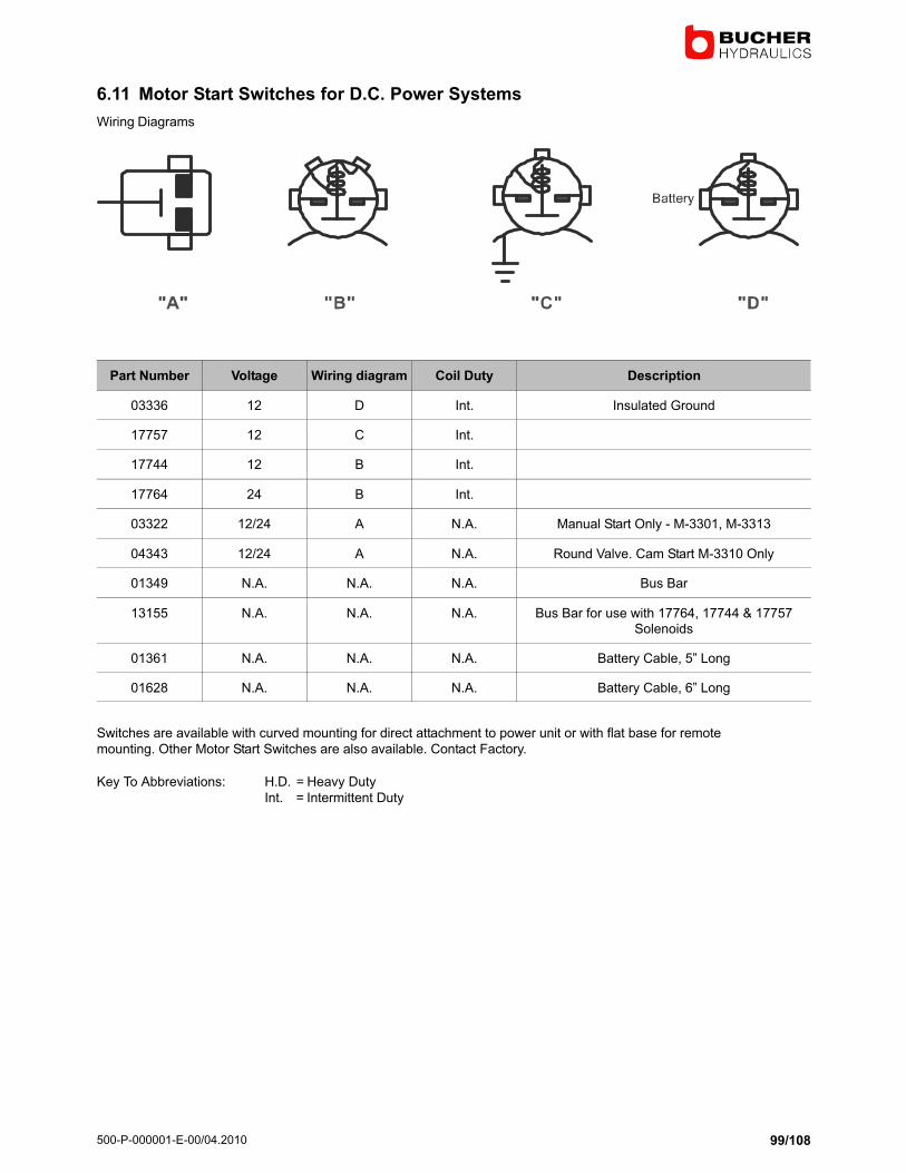
500−P−000001−E−00/04.2010
99/108
6.11 Motor Start Switches for D.C. Power Systems
Wiring Diagrams
Part Number Voltage Wiring diagram Coil Duty Description
03336 12 D Int. Insulated Ground
17757 12 C Int.
17744 12 B Int.
17764 24 B Int.
03322 12/24 A N.A. Manual Start Only − M−3301, M−3313
04343 12/24 A N.A. Round Valve. Cam Start M−3310 Only
01349 N.A. N.A. N.A. Bus Bar
13155 N.A. N.A. N.A. Bus Bar for use with 17764, 17744 & 17757Solenoids
01361 N.A. N.A. N.A. Battery Cable, 5" Long
01628 N.A. N.A. N.A. Battery Cable, 6" Long
Switches are available with curved mounting for direct attachment to power unit or with flat base for remote
mounting. Other Motor Start Switches are also available. Contact Factory.
Key To Abbreviations: H.D. = Heavy Duty
Int. = Intermittent Duty

500−P−000001−E−00/04.2010
100/108
6.12 Control Boxes
Figure1
Figure3
Figure2
Figure4
Figure Switch Symbol Models used on Part Number
1* M−3303, M−3319, M−3314, M−3519, M−3541 03409
1* M−642, M−3551, M−3515, M−3554 03487
1* M−3528 M−3303, M−3319, M−3314, M−3519, M−719 03451
1* M−642, M−3551, M−3515, M−3530, M−3547, M−3554 07995
1* M−680’S 03197 (Detented)03201 (Non−Detendet)
1* M−3303, M−3315, M−3314 07993
NOTE: The above Control Stations may be used with other Power Units. Consult Factory.
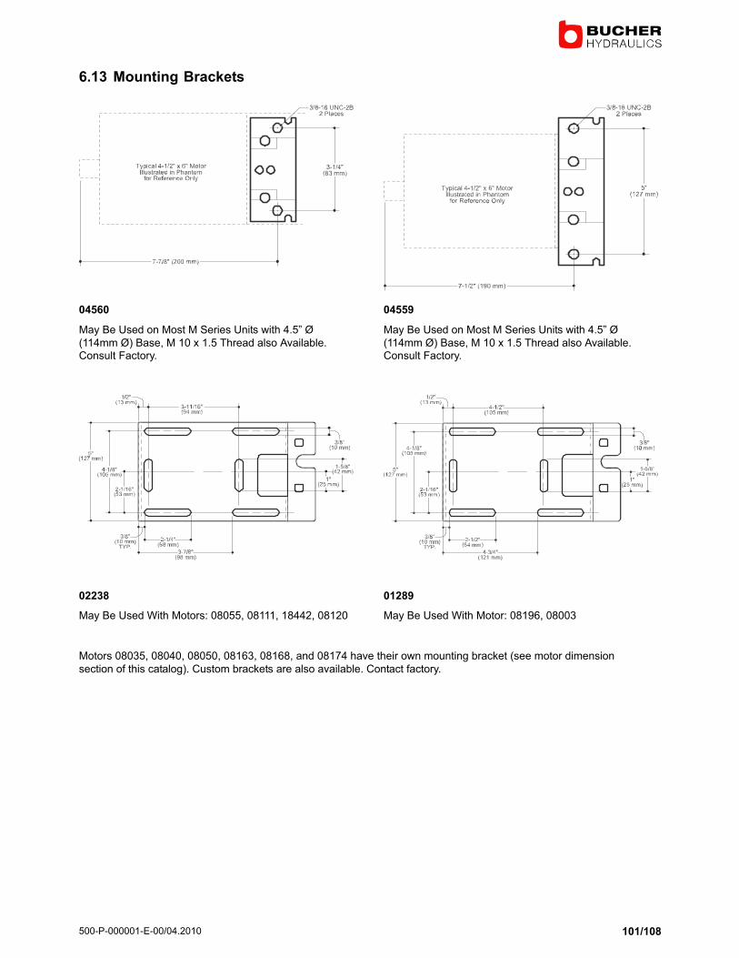
500−P−000001−E−00/04.2010
101/108
6.13 Mounting Brackets
04560
May Be Used on Most M Series Units with 4.5" Ø
(114mm Ø) Base, M 10 x 1.5 Thread also Available.Consult Factory.
02238
May Be Used With Motors: 08055, 08111, 18442, 08120
04559
May Be Used on Most M Series Units with 4.5" Ø
(114mm Ø) Base, M 10 x 1.5 Thread also Available.Consult Factory.
01289
May Be Used With Motor: 08196, 08003
Motors 08035, 08040, 08050, 08163, 08168, and 08174 have their own mounting bracket (see motor dimension
section of this catalog). Custom brackets are also available. Contact factory.

500−P−000001−E−00/04.2010
102/108
6.14 Popular Accessories For DC Power Systems
Part Number Description
01436 Sight Level/Temperature Gauge. For Use on Large Reservoirs Only.
01516 Reservoir Breather, Flush Mount, .375" NPT. Cross Scored.
03171 Reservoir Breather, .375" NPT.
01143 Reservoir Breather, .750" NPT.
01670 Sight Glass. 3/4" NPT.
03219 Pressure Gauge. Liquid Filled. 1/4" NPT. 0−500 PSI.
01434 Pressure Gauge. Liquid Filled. 1/4" NPT. 0−3000 PSI.
01790 Pressure Gauge. Liquid Filled. 1/4" NPT. 0−5000 PSI.
00570 Gauge Shutoff. 1/4" NPT.
00904 Flow Control, Adjustable. Non Pressure Compensated. 1/4" NPT. F x F For Flows to 3.0 GPM (11.4 LPM).
01720−X.XX Flow Control, Pressure Compensated. Fixed. 1/4" NPT F x F. Other Types Available. Specify Flow Required.
01875 Filter, Return Line. 15 GPM. 10 Micron Nominal.
04369 Filter, Return Line. 5 GPM. 10 Micron Nominal.
01425 Filter/Breather, Chrome Plated. Basket Strainer.
04202 M−310 Cam Start Switch Conversion Kit.
07157 Relief Valve, Cartridge. 1500−3000 PSI. Other Pressure Ranges Also Available.
01506 Terminal Cover, Rubber. #4 Cable.
03981 Hand Pump, Standard.
03987 Hand Pump, Mini Direct, Right Hand. High Pressure − Low Displacement.
03943 Hand Pump, Mini Direct, Left Hand. High Pressure − Low Displacement.
07435 Hand Pump, High Pressure − Heavy Duty.
03695 Valve Cover Cap Kit, M−693.
Other Available Options and Accessories Include:
� Float Switches
� Special Manifold Circuits
� Pressure Switches
� Multi−Function Valve Controls − Monoblock and Sectional
� Special Cartridge, Industrial and Manual Valve Configurations.
NOTE: Accessories Will Not Fit Every Model. Please Contact the Factory For Assistance.

500−P−000001−E−00/04.2010
103/108
6.15 Monarch Hand Pumps
Standard − Standard Displacement (0.50 In3/Stroke) High Pressure − Low Displacement (0.25 In3/Stroke) High Pressure/
Heavy Duty − Standard Displacement (0.50 In3/Stroke)
Note: It is recommended that pins and piston be periodically lubricated to prolong hand pump life.
6.16 Standard Hand Pumps
Description
� 0.50 In3/Stroke (8.20 Cm3/Stroke)
� Single Acting
� 2000 PSI (138 Bar)
� Outlet Port: 1/4" NPTF
� Ideal For Emergency Back−Up Application in Case of
Primary Pump Failure
� Horizontal or Vertical Mounting
� Designed for Mounting Directly to Monarch Power Units
� Handle May Positioned in any Direction
� Release Valve (Use Handle for Actuating)
� Supplied with Painted Steel "Comfort Grip" Handle
� All Exposed Materials are Aluminum or Plated Steel for
Corrosion Resistance
Popular Options
� Remote Mounting
� Ports. Other Styles Available
� Relief Valve
� Integral Reservoir
Schematic

500−P−000001−E−00/04.2010
104/108
6.17 High Pressure − Low Displacement Hand Pump
Description
� 0.50 In3/Stroke (8.20 Cm3/Stroke)
� Single Acting
� 3500 PSI (240 Bar)
� Outlet Port: 1/4" NPTF
� Ideal For Emergency Back−Up Application in Case of
Primary Pump Failure
� Horizontal or Vertical Mounting
� Designed for Mounting Directly to Monarch Power Units
� Handle May Positioned in any Direction
� Release Valve (Use Handle for Actuating)
� Supplied with Painted Steel "Comfort Grip" Handle
� All Exposed Materials are Aluminum or Plated Steel for
Corrosion Resistance
Popular Options
� Remote Mounting
� Ports. Other Styles Available
� Relief Valve
Schematic
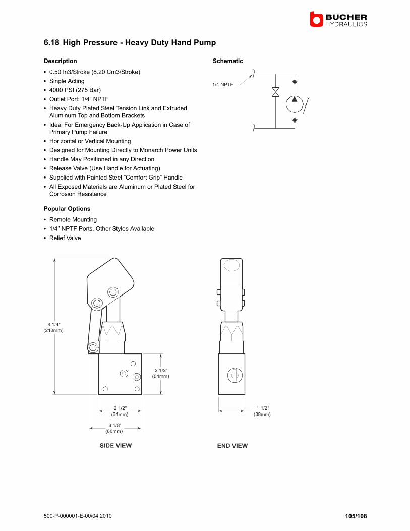
500−P−000001−E−00/04.2010
105/108
6.18 High Pressure − Heavy Duty Hand Pump
Description
� 0.50 In3/Stroke (8.20 Cm3/Stroke)
� Single Acting
� 4000 PSI (275 Bar)
� Outlet Port: 1/4" NPTF
� Heavy Duty Plated Steel Tension Link and Extruded
Aluminum Top and Bottom Brackets
� Ideal For Emergency Back−Up Application in Case of
Primary Pump Failure
� Horizontal or Vertical Mounting
� Designed for Mounting Directly to Monarch Power Units
� Handle May Positioned in any Direction
� Release Valve (Use Handle for Actuating)
� Supplied with Painted Steel "Comfort Grip" Handle
� All Exposed Materials are Aluminum or Plated Steel for
Corrosion Resistance
Popular Options
� Remote Mounting
� 1/4" NPTF Ports. Other Styles Available
� Relief Valve
Schematic

500−P−000001−E−00/04.2010
106/108
6.19 Heavy Duty Remote Hand Pump
6.20 Model H−100 Series Hand Pumps With Reservoirs
Hand Pump with Relief Valve and Reservoir
� 12139 Standard Duty Hand Pump with Relief Valve
� 12140 Heavy Duty Hand Pump with Relief Valve

500−P−000001−E−00/04.2010
107/108
6.21 Battery Cables
� For best results, Monarch would recommend that you increase 1 or 2 cable sizes above the
minimum shown above. Select cable size so that your cable length and maximum amp drawfalls below and to the left of curve.
� Curve describers a 1 volt loss in the battery cable itself.
� Total length of battery cable(s) including all ground cables.
Example: With maximum current draw of 200 amps and total cable length of 28 ft (7.82m), Select #1 gauge (.28 in/7.1mm)
or larger.

500−P−000001−E−00/04.2010
108/108
6.22 Limited 1 Year Warranty
Bucher Hydraulics, Inc. (ˆBucher˜) makes the following warranty to any party who purchases this Bucher Hydraulics, Inc. prod-
uct directly from Bucher Hydraulics, Inc. with the intention of either reselling this Bucher Hydraulics, Inc. product or
incorporating it into or attaching it to some other product (ˆthe purchaser˜).
Bucher Hydraulics, Inc. warrants to the purchaser that this product is free from any substantial defects in materials and work-
manship. If this product proves to be defective in materials or workmanship during the period of this warranty, Bucher Hy-draulics, Inc. will repair or replace, at it´s option, the defective product free of charge (except for transportation charges as
provided below). The period of this warranty is the (1) year period beginning from the date of shipment of this Bucher Hy-
draulics, Inc. product by Bucher Hydraulics, Inc. to the purchaser.
To obtain warranty service, the purchaser must call Bucher Hydraulics, Inc. to have a return goods authorization number as-
signed to them. The purchaser should then send the product claimed to be defective within the warranty period, transportationprepaid, to: Bucher Hydraulics, Inc., 1363 Michigan Street N.E., Grand Rapids, MI. 49503, USA. Bucher Hydraulics, Inc. will
then repair or replace, at it´s option, items which it finds to have been defective. Bucher Hydraulics, Inc. will return such repaired
or replacement items to the sender free of charge. Items claimed by the purchaser, but not found by Bucher Hydraulics, Inc.,
to be defective will be returned to the purchaser by a reasonably expeditious means at the purchaser´s expense. This expense
may include labor charges incurred from inspecting the unit.
This warranty does not extend to any failure of this Bucher Hydraulics, Inc. product to perform as warranted hereinabove
which is caused by misuse, abuse or material alteration of this product, or any negligence in connection with the installation,
service, or use of this product by any person other than Bucher Hydraulics, Inc.
Bucher Hydraulics, Inc. hereby expressly disclaims any liability for consequential damages to property other than this BucherHydraulics, Inc. product to perform as warranted hereinabove.
Note: Supersedes all former warranties written or implied.
� 2010 by Bucher Hydraulics Inc. 1363 Michigan Street NE
All rights reserved.
Data is provided for the purpose of product description only, and must not be construed as warranted characteristics in the legal sense. The
information does not relieve users from the duty of conducting their own evaluations and tests. Because the products are subject to continual
improvement, we reserve the right to amend the product specifications contained in this catalogue.
Classification: 450