DC-DC Converters Using GaN for Collider Physics Detectors · 1 Satish K Dhawan. Yale University....
33
1 Satish K Dhawan Yale University ECPE SiC & GaN User Forum: Potential of Wide Bandgap Semiconductors in Power Electronic Applications ECPE: European Center for Power Electronics e.V. 1 - 2 September 201, Birmingham, U.K. DC-DC Converters Using GaN for Collider Physics Detectors http://shaktipower.sites.yale.edu/ [email protected]
Transcript of DC-DC Converters Using GaN for Collider Physics Detectors · 1 Satish K Dhawan. Yale University....

1
Satish K DhawanYale University
ECPE SiC & GaN User Forum: Potential of Wide Bandgap
Semiconductors in Power Electronic ApplicationsECPE: European Center for Power Electronics e.V.
1 -
2 September 201, Birmingham, U.K.
DC-DC Converters Using GaN for Collider Physics Detectors
http://shaktipower.sites.yale.edu/[email protected]

2
Topics AgendaCERN: Current Detectors & Powering
CMS ECAL detector
Environment: Magnetic field & Radiation
Limits of Silicon
Why GaN ?
GaN Tests
Linear Collider – Low radiation but needs lower mass powering
Market Trends
Summary Keep Environment cool

3

4

5
6

7

8
9
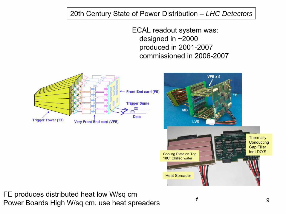
ECAL readout system was: designed in ~2000 produced in 2001-2007 commissioned in 2006-2007
20th Century State of Power Distribution –
LHC Detectors
Heat Spreader
Cooling Plate on Top18C: Chilled water
ThermallyConductingGap Filler for LDO’S
FE produces distributed heat low W/sq cmPower Boards High W/sq cm. use heat spreaders

10
CMS ECAL Super modules

11
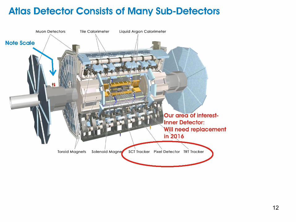
12

13
13
Transformer18 KV380 V3 Phase UPS
BatteriesIsolation
Transformer
220 V 3 Phase
Guess work Efficiency %
99.5 %98 %97 %
Power Grid600 KV 50 MW300 KM
TransformerNuclear
GeneratingPlant
Transformer33 KV
99.5 % 99 %80 % 100 Km
50 ‐100 m
From Experts Efficiency %
5 ‐
6 Km
230 V 3 Phase AC to DC
Rectifier &PFC
385 V Wiener Maraton
PS
6.3 V
75 ‐79 %
140 mCableLoss = 3%
40 mLoad
40 %
Power delivery Efficiency
= 30 %
Power Chain Efficiency for CMS ECAL
with Power for Heat Removal
= 20 %
Represents the efficiency of power delivery
to a physics detector, e.g. ECal
It takes 2 watts of power to remove 1 watt of heat load
125 KW
417 KW
625 KW

14
Power Efficiency _ Inefficiency _ Wasted Power

15
Power Supply cables 30 – 140 metersPoint of Load RegulatorsDC-DC Buck ConvertersOther schemes are not feasible due to constraintsRadiation, Magnetic Field (Air Core Coils), Switching Noise, Low Mass
HV –
Low Voltage Converters: Reduce cable delivery losses
16
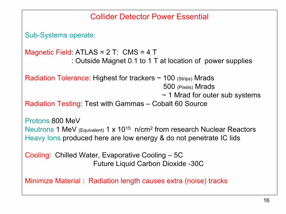
Collider Detector Power Essential
Sub-Systems operate:
Magnetic Field: ATLAS = 2 T: CMS = 4 T: Outside Magnet 0.1 to 1 T at location of power supplies
Radiation
Tolerance: Highest for trackers ~ 100 (Strips)
Mrads500 (Pixels)
Mrads~ 1 Mrad
for outer sub systemsRadiation
Testing: Test with Gammas –
Cobalt 60 Source
Protons
800 MeVNeutrons
1 MeV
(Equivalent)
1 x 10¹⁵
n/cm2
from research Nuclear Reactors Heavy Ions
produced here are low energy & do not penetrate IC lids
Cooling: Chilled Water, Evaporative Cooling –
5CFuture Liquid Carbon Dioxide -30C
Minimize Material : Radiation length causes extra (noise) tracks

17
Buck Regulator Efficiency after 100 Mrad dosage
40
45
50
55
60
65
70
75
80
0 1 2 3 4 5 6
Output Current Amps
Pow
er E
ffici
ency
%
AfterExposure
BeforeExposure
Found out at Power Technology conference 0.25 µm LithographyIrradiated Stopped on St. Valentines Day 2007We reported @ TWEPP 2008 - IHP was foundry for EN5360
Enpirion EN5360With Integrated Inductor

18
Magnetic Field Effect
7 Tesla Field Chemistry DepartmentSuper Conducting Magnet in Persistence ModeEffect:Vout = 3.545 Outside Vout = 3.546 Edge of magnetVout = 3.549 Center of magnetChange= Increased Vout 1 part in 900 at 7T
Buck Converterwith Air Coil

19
Coupled Air Core InductorConnected in Series
Plug In Card with Shielded Buck Inductor
0.35 mm1.5 mm
Top Bottom
3 Oz PCB 57 460.25 mm Cu Foil 19.4 17
Spiral Coils Resistance in mΩ
12 V 2.5 V@ 6 amps
Different VersionsConverter Chips
Max8654 monolithicIR8341 3 die MCM
CoilsEmbedded 3oz cuSolenoid 15 mΩSpiral Etched 0.25mm

20
MAX8654 with embedded coils (#12), external coils (#17) or Renco Solenoid (#2) Vout=2.5 V
0
10
20
30
40
50
60
70
80
90
100
0 0.5 1 1.5 2 2.5 3 3.5 4 4.5 5Output current (amps)
Effic
ienc
y (%
)
MAX #12, Vin = 11.9 V MAX #17, Vin = 11.8 V MAX #2, Vin = 12.0 V
PCB embedded Coil
Copper Coils
Solenoid

21
Plug in Card 1 cm from Coilfacing Sensor
20 μm Al foilshielding
Coil Type Power
Input Noise
electrons rms
SolenoidDC -
DC 881
Solenoid Linear 885
Spiral Coil
DC -
DC 666
Spiral Coil Linear 664
Noise Tests with Silicon SensorsTest @ BNL
Test @ Liverpool
512 Strips –
100 µm Pitch51 mm x 84 mm
Only One Chip Bonded
Radiated NoiseNo Conducted Noise

22Many more tested but similar failure-Thin oxide converters survive > 200 Krads
Ionizing Radiation Results – Commercial Converters
Dose rate= 0.2 Mrad/hr
5-
12 nm Gate Oxide

23
Buck Regulator Efficiency after 100 Mrad dosage
40
45
50
55
60
65
70
75
80
0 1 2 3 4 5 6
Output Current Amps
Pow
er E
ffici
ency
%
AfterExposure
BeforeExposure
Enpirion EN5360
Why this Survived100 Mrads ?

24
Sachs et. al. IEEE Trans. Nuclear Science NS-31, 1249 (1984)
Threshold Shift vs Gate Oxide Thickness
Hole removal process by tunneling inthin-oxide MOS Structures
Book. Timothy R Oldham “Ionizing Radiation Effects in MOS Oxides”
1999 World Scientific
++ + +++ + +++ + +++ + +
++ + +
++ + +
SiSiO2
e--e--
Poly-
Si
Gate
Tunneling Region
Dosage = 150 Krads

25
Controller : Low Voltage
High Voltage: Switches –
some candidates HV & Thin oxide
RF Process LDMOS, Drain Extension, Deep Diffusion etc
>> 20 Volts HEMT GaN on Silicon, Silicon Carbide, Sapphire
Can We HaveHigh Radiation Tolerance & Higher Voltage Together ???
Higher radiation tolerance needs thin oxide while higher voltage needs thicker oxide –
Contradiction ?
Mixed signal power designs from TI, TSMC, IBM etc -
0.18 µm & 0.13 µmAutomobile Market. Voltage ratings 10 -
80 VoltsDeep sub-micron but thick oxide

26
XY Semi (VD = 12V)2 Amp FET‐ HVMOS20080720 Process
00.020.040.060.080.1
0.12
0 0.5 1 1.5
Vg (Volts)
Id (A
mps)I
0 rad
1 Mrad
5.4 Mrad
33 Mrad
52 Mrad
IHP PMOS TransistorVG versus ID at selected Gamma Doses
0
0.2
0.4
0.6
0.8
1
0 0.5 1 1.5 2 2.5VG (Volts)
I D (m
A)
Pre-Irradiation
13 Mrad
22 Mrad
35 Mrad
53 Mrad
IHP NMOS TransistorVG versus ID at Selected Gamma Doses
0
0.5
1
1.5
2
2.5
0 0.5 1 1.5 2 2.5VG (Volts)
I D (m
A)
Pre-irradiation
13 Mrad
22 Mrad
35 Mrad

27
10MHz,12Vin,48ns
0%10%20%30%40%50%60%70%80%90%
100%
0 2 4 6 8 10
Iout (A)
Effic
ienc
y(%)
Frequency Response IR’s
Engineering sample in 2009Half Bridge with CMOS Driver
Good efficiency to >12 MHz Driver limited
International Rectifier: Supplied sample board under NDA
28
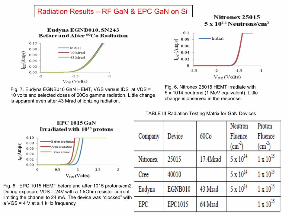
Fig. 6. Nitronex 25015 HEMT irradiate with 5 x 10¹⁴ neutrons (1 MeV
equivalent). Little change is observed in the response.
Fig. 7. Eudyna EGNB010 GaN HEMT, VGS versus IDS at VDS = 10 volts and selected doses of 60Co gamma radiation. Little change is apparent even after 43 Mrad
of ionizing radiation.
Fig. 8. EPC 1015 HEMT before and after 1015 protons/cm2. During exposure VDS = 24V with a 1 kOhm
resistor current limiting the channel to 24 mA. The device was “clocked”
with a VGS = 4 V at a 1 kHz frequency
TABLE III Radiation Testing Matrix for GaN Devices
Radiation Results –
RF GaN & EPC GaN on Si
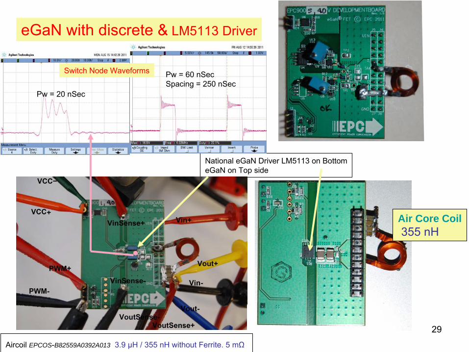
29Aircoil EPCOS-B82559A0392A013 3.9 µH / 355 nH
without Ferrite. 5 mΩ
National eGaN Driver LM5113 on BottomeGaN on Top side
Air Core Coil355 nH
Switch Node Waveforms
Pw = 20 nSec
Pw = 60 nSecSpacing = 250 nSec
eGaN
with discrete &
LM5113 Driver

30
70%
72%
74%
76%
78%
80%
82%
84%
86%
88%
90%
0 1 2 3 4 5 6
Output current (A)
Efficiency
24V to 2.5V @ 2MHzWith driver lossFerrite core12V to 2.5V @ 4MHzwith driver lossferrite core
24V to 2.5V 2 MHz12V to 2.5V 4 MHz
MnZn Ferrite Coil 744308euro33 377 nH
0.37 mΩAircoil EPCOS-B82559A0392A013 3.9 µH / 355 nH
without Ferrite. 5 mΩ

31
Electron Linear Collider produce low radiationbut material in the interaction regions must be minimized
High Frequency operation for lower coil size / materialCommercial cell phone converters 6 - 8 MHz, 1 amp, 5.5 Vin1 -2 turn coilFabricate PCB & Test Power Supply in a PackageCoil simulation needs collaborators ??Coil may be buried in the detector PCBFeasibility report due summer 2012

32
Controller CMOS Driver GaN FETs
LM5113EPC FETs
Freely Available
Demo PCB From EPC
Chip on board
Year 2013 -2014
Monolithic for MOSFETs
Chip on board 1Q 2012
GaN Driver & FET Half Bridge
Market Trend
FPGA Based0.13/0.25 µm
Power Supply in PackageRadiation Hard

33
Top of the World is Cool but lonely !Let us keep it cool with highly efficient PS
Swimming is Great at the North PoleAugust 2010 Fairbanks, Alaska was 33 C –
Bye Bye Glaciers !
Working on Physics Power Supply Is not considered Glamorous
More Details: http://shaktipower.sites.yale.edu
Click on Recent seminars/