DC-DC Converters PCB Mount Type MGW1R5 MG W 1R5 … · MG-16 MGW3 DC-DC Converters PCB Mount Type...
12
MG-14 MGW1R5 DC-DC Converters PCB Mount Type MG W 1R5 24 12 -O Ordering information 1Series name 2Dual output 3Output wattage 4Input voltage 5Output voltage 6Optional R 1 2 3 4 5 6 MODEL MGW1R50512 MGW1R50515 MGW1R51212 MGW1R51215 MGW1R52412 MGW1R52415 MGW1R54812 MGW1R54815 MAX OUTPUT WATTAGE[W] 1.56 1.50 1.56 1.50 1.56 1.50 1.56 1.50 DC OUTPUT VOLTAGE[V] *1 ±12 or +24 ±15 or +30 ±12 or +24 ±15 or +30 ±12 or +24 ±15 or +30 ±12 or +24 ±15 or +30 CURRENT[A] 0.065 0.05 0.065 0.05 0.065 0.05 0.065 0.05 SPECIFICATIONS MODEL MGW1R50512 MGW1R50515 MGW1R51212 MGW1R51215 MGW1R52412 MGW1R52415 MGW1R54812 MGW1R54815 INPUT VOLTAGE[V] DC4.5 - 9 (Surge voltage 12.5V, 100ms max) DC9 - 18 (Surge voltage 25V, 100ms max) DC18 - 36 (Surge voltage 50V, 100ms max) DC36 - 76 (Surge voltage 100V, 100ms max) CURRENT[A] *2 0.38typ 0.38typ 0.16typ 0.16typ 0.080typ 0.079typ 0.041typ 0.040typ EFFICIENCY[%] *2 83typ 81typ 83typ 81typ 82typ 80typ 81typ 80typ OUTPUT VOLTAGE[V] ±12 or +24 ±15 or +30 ±12 or +24 ±15 or +30 ±12 or +24 ±15 or +30 ±12 or +24 ±15 or +30 CURRENT[A] 0.065 0.05 0.065 0.05 0.065 0.05 0.065 0.05 LINE REGULATION[mV] 60max 75max 60max 75max 60max 75max 60max 75max LOAD REGULATION[mV] *3 480max 600max 480max 600max 480max 600max 480max 600max *4 600max 750max 600max 750max 600max 750max 600max 750max RIPPLE[mVp-p] *5 150max 150max 150max 150max 150max 150max 150max 150max RIPPLE NOISE[mVp-p] *5 200max 200max 200max 200max 200max 200max 200max 200max TEMPERATURE REGULATION[mV] -20 to +85C 210max 260max 210max 260max 210max 260max 210max 260max -40 to +85C 320max 390max 320max 390max 320max 390max 320max 390max DRIFT[mV] *6 48max 60max 48max 60max 48max 60max 48max 60max START-UP TIME[ms] 30max (Minimum input, Io=100%) OUTPUT VOLTAGE SETTING[V] 11.64 - 12.36 14.55 - 15.45 11.64 - 12.36 14.55 - 15.45 11.64 - 12.36 14.55 - 15.45 11.64 - 12.36 14.55 - 15.45 PROTECTION CIRCUIT OVERCURRENT PROTECTION Works over 105% of rating and recovers automatically ISOLATION INPUT-OUTPUT DC1,500V or AC1,000V 1minute, Cutoff current=10mA, DC500V 1,000MW min (20±15C) ENVIRONMENT OPERATING TEMP.,HUMID.AND ALTITUDE -40 to +85C, 20 to 95%RH (Non condensing) (Required derating), 5,000m (16,400feet) max STORAGE TEMP.,HUMID.AND ALTITUDE -40 to +100C, 20 to 95%RH (Non condensing), 9,000m (30,000feet) max VIBRATION 10 - 55Hz 98.0m/s 2 (10G), 3minute period, 60minutes each along X, Y and Z axis IMPACT 490.3m/s 2 (50G) 11ms, once each along X, Y and Z axis SAFETY AGENCY APPROVALS UL60950-1, C-UL, EN60950-1 OTHERS CASE SIZE/WEIGHT 17.0X12.0X8.5mm [0.67X0.48X0.34 inches] (WXHXD) / 4g max COOLING METHOD Convection/Forced air *1 Single output +24V, +30V with no use of COM. *2 Rated input 5V, 12V, 24V or 48V DC Io=100% *3 Symmetrical loading from 20% to 100%. *4 Symmetrical loading from 0% to 100%. *5 Ripple and Ripple Noise is measured by using test board with ceramic capacitor 1 F at 50mm from output pins. (20MHz Osilloscope) *6 Drift is the DC output accuracy for eight hours period after a half-hour warm-up at 25C. * Parallel operation with other model is not possible.
Transcript of DC-DC Converters PCB Mount Type MGW1R5 MG W 1R5 … · MG-16 MGW3 DC-DC Converters PCB Mount Type...
MG-14
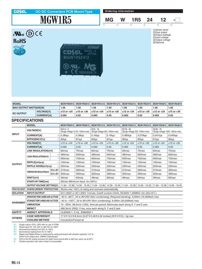
MGW1R5DC-DC Converters PCB Mount Type
MG W 1R5 24 12 -O
Ordering information
1 Series name2 Dual output3 Output wattage4 Input voltage5 Output voltage6 Optional
R
1 2 3 4 5 6
MODEL MGW1R50512 MGW1R50515 MGW1R51212 MGW1R51215 MGW1R52412 MGW1R52415 MGW1R54812 MGW1R54815
MAX OUTPUT WATTAGE[W] 1.56 1.50 1.56 1.50 1.56 1.50 1.56 1.50
DC OUTPUT VOLTAGE[V] *1 ±12 or +24 ±15 or +30 ±12 or +24 ±15 or +30 ±12 or +24 ±15 or +30 ±12 or +24 ±15 or +30
CURRENT[A] 0.065 0.05 0.065 0.05 0.065 0.05 0.065 0.05
SPECIFICATIONSMODEL MGW1R50512 MGW1R50515 MGW1R51212 MGW1R51215 MGW1R52412 MGW1R52415 MGW1R54812 MGW1R54815
INPUT
VOLTAGE[V] DC4.5 - 9 (Surge voltage 12.5V, 100ms max)
DC9 - 18 (Surge voltage 25V, 100ms max)
DC18 - 36 (Surge voltage 50V, 100ms max)
DC36 - 76 (Surge voltage 100V, 100ms max)
CURRENT[A] *2 0.38typ 0.38typ 0.16typ 0.16typ 0.080typ 0.079typ 0.041typ 0.040typ
EFFICIENCY[%] *2 83typ 81typ 83typ 81typ 82typ 80typ 81typ 80typ
OUTPUT
VOLTAGE[V] ±12 or +24 ±15 or +30 ±12 or +24 ±15 or +30 ±12 or +24 ±15 or +30 ±12 or +24 ±15 or +30
CURRENT[A] 0.065 0.05 0.065 0.05 0.065 0.05 0.065 0.05
LINE REGULATION[mV] 60max 75max 60max 75max 60max 75max 60max 75max
LOAD REGULATION[mV]*3 480max 600max 480max 600max 480max 600max 480max 600max*4 600max 750max 600max 750max 600max 750max 600max 750max
RIPPLE[mVp-p] *5 150max 150max 150max 150max 150max 150max 150max 150max
RIPPLE NOISE[mVp-p] *5 200max 200max 200max 200max 200max 200max 200max 200max
TEMPERATURE REGULATION[mV]-20 to +85C 210max 260max 210max 260max 210max 260max 210max 260max
-40 to +85C 320max 390max 320max 390max 320max 390max 320max 390max
DRIFT[mV] *6 48max 60max 48max 60max 48max 60max 48max 60max
START-UP TIME[ms] 30max (Minimum input, Io=100%)
OUTPUT VOLTAGE SETTING[V] 11.64 - 12.36 14.55 - 15.45 11.64 - 12.36 14.55 - 15.45 11.64 - 12.36 14.55 - 15.45 11.64 - 12.36 14.55 - 15.45
PROTECTION CIRCUIT OVERCURRENT PROTECTION Works over 105% of rating and recovers automatically
ISOLATION INPUT-OUTPUT DC1,500V or AC1,000V 1minute, Cutoff current=10mA, DC500V 1,000MW min (20±15C)
ENVIRONMENT
OPERATING TEMP.,HUMID.AND ALTITUDE -40 to +85C, 20 to 95%RH (Non condensing) (Required derating), 5,000m (16,400feet) max
STORAGE TEMP.,HUMID.AND ALTITUDE -40 to +100C, 20 to 95%RH (Non condensing), 9,000m (30,000feet) max
VIBRATION 10 - 55Hz 98.0m/s2 (10G), 3minute period, 60minutes each along X, Y and Z axis
IMPACT 490.3m/s2 (50G) 11ms, once each along X, Y and Z axis
SAFETY AGENCY APPROVALS UL60950-1, C-UL, EN60950-1
OTHERSCASE SIZE/WEIGHT 17.0X12.0X8.5mm [0.67X0.48X0.34 inches] (WXHXD) / 4g max
COOLING METHOD Convection/Forced air
*1 Single output +24V, +30V with no use of COM.*2 Rated input 5V, 12V, 24V or 48V DC Io=100%*3 Symmetrical loading from 20% to 100%.*4 Symmetrical loading from 0% to 100%.*5 Ripple and Ripple Noise is measured by using test board with ceramic capacitor 1 F at
50mm from output pins. (20MHz Osilloscope)*6 Drift is the DC output accuracy for eight hours period after a half-hour warm-up at 25C.* Parallel operation with other model is not possible.

MG-15
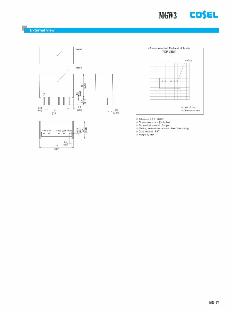
MGW1R5External view
(TOP VIEW)¶Recommended Pad and Hole dia.
Model
Model
-Vin +Vin +Vout COM -Vout
2.2
12
0.5
3.5
8.5
17
12.72.54
2.8
0.25
0.5
¶¶
Unit : 0.1inchDimension : mm
¶ Tolerance ±0.5 [±0.02]¶ Dimensions in mm, [ ]= inches¶ Pin terminal material : Copper¶ Planting treatment of terminal : Lead free plating¶ Case material : PBT¶ Weight 4g max
[0.3
4]
[0.0
1]
[0.1
4]
[0.0
2]
[0.4
8]
[0.5][0.1] [0.09]
[0.67]
[0.02]
[0.11]
5-f0.9

MG-16
MGW3DC-DC Converters PCB Mount Type
MG W 3 24 12 -O
Ordering information
1 Series name2 Dual output3 Output wattage4 Input voltage5 Output voltage6 Optional
R
1 2 3 4 5 6
*1 Single output +24V, +30V with no use of COM.*2 Rated input 5V, 12V, 24V or 48V DC Io=100%*3 Symmetrical loading from 20% to 100%.*4 Symmetrical loading from 0% to 100%.*5 Ripple and Ripple Noise is measured by using test board with ceramic capacitor 1 F at
50mm from output pins. (20MHz Osilloscope)*6 Drift is the DC output accuracy for eight hours period after a half-hour warm-up at 25C.* Parallel operation with other model is not possible.
MODEL MGW30512 MGW30515 MGW31212 MGW31215 MGW32412 MGW32415 MGW34812 MGW34815
MAX OUTPUT WATTAGE[W] 3.12 3.00 3.12 3.00 3.12 3.00 3.12 3.00
DC OUTPUT VOLTAGE[V] *1 ±12 or +24 ±15 or +30 ±12 or +24 ±15 or +30 ±12 or +24 ±15 or +30 ±12 or +24 ±15 or +30
CURRENT[A] 0.13 0.1 0.13 0.1 0.13 0.1 0.13 0.1
SPECIFICATIONSMODEL MGW30512 MGW30515 MGW31212 MGW31215 MGW32412 MGW32415 MGW34812 MGW34815
INPUT
VOLTAGE[V] DC4.5 - 9 (Surge voltage 12.5V, 100ms max)
DC9 - 18 (Surge voltage 25V, 100ms max)
DC18 - 36 (Surge voltage 50V, 100ms max)
DC36 - 76 (Surge voltage 100V, 100ms max)
CURRENT[A] *2 0.76typ 0.74typ 0.31typ 0.31typ 0.16typ 0.16typ 0.080typ 0.077typ
EFFICIENCY[%] *2 83typ 82typ 84typ 83typ 83typ 83typ 82typ 82typ
OUTPUT
VOLTAGE[V] ±12 or +24 ±15 or +30 ±12 or +24 ±15 or +30 ±12 or +24 ±15 or +30 ±12 or +24 ±15 or +30
CURRENT[A] 0.13 0.1 0.13 0.1 0.13 0.1 0.13 0.1
LINE REGULATION[mV] 60max 75max 60max 75max 60max 75max 60max 75max
LOAD REGULATION[mV]*3 480max 600max 480max 600max 480max 600max 480max 600max*4 600max 750max 600max 750max 600max 750max 600max 750max
RIPPLE[mVp-p] *5 150max 150max 150max 150max 150max 150max 150max 150max
RIPPLE NOISE[mVp-p] *5 200max 200max 200max 200max 200max 200max 200max 200max
TEMPERATURE REGULATION[mV]-20 to +70C 180max 220max 180max 220max 180max 220max 180max 220max
-40 to +70C 290max 340max 290max 340max 290max 340max 290max 340max
DRIFT[mV] *6 48max 60max 48max 60max 48max 60max 48max 60max
START-UP TIME[ms] 30max (Minimum input, Io=100%)
OUTPUT VOLTAGE SETTING[V] 11.64 - 12.36 14.55 - 15.45 11.64 - 12.36 14.55 - 15.45 11.64 - 12.36 14.55 - 15.45 11.64 - 12.36 14.55 - 15.45
PROTECTION CIRCUIT OVERCURRENT PROTECTION Works over 105% of rating and recovers automatically
ISOLATION INPUT-OUTPUT DC1,500V or AC1,000V 1minute, Cutoff current=10mA, DC500V 1,000MW min (20±15C)
ENVIRONMENT
OPERATING TEMP.,HUMID.AND ALTITUDE -40 to +85C, 20 to 95%RH (Non condensing) (Required derating), 5,000m (16,400feet) max
STORAGE TEMP.,HUMID.AND ALTITUDE -40 to +100C, 20 to 95%RH (Non condensing), 9,000m (30,000feet) max
VIBRATION 10 - 55Hz 98.0m/s2 (10G), 3minute period, 60minutes each along X, Y and Z axis
IMPACT 490.3m/s2 (50G) 11ms, once each along X, Y and Z axis
SAFETY AGENCY APPROVALS UL60950-1, C-UL, EN60950-1
OTHERSCASE SIZE/WEIGHT 17.0X12.0X8.5mm [0.67X0.48X0.34 inches] (WXHXD) / 4g max
COOLING METHOD Convection/Forced air
MG-17
MGW3External view
(TOP VIEW)¶Recommended Pad and Hole dia.
Model
Model
-Vin +Vin +Vout COM -Vout
2.2
12
0.5
3.5
8.5
17
12.72.54
2.8
0.25
0.5
¶¶
Unit : 0.1inchDimension : mm
¶ Tolerance ±0.5 [±0.02]¶ Dimensions in mm, [ ]= inches¶ Pin terminal material : Copper¶ Planting treatment of terminal : Lead free plating¶ Case material : PBT¶ Weight 4g max
[0.3
4]
[0.0
1]
[0.1
4]
[0.0
2]
[0.4
8]
[0.5][0.1] [0.09]
[0.67]
[0.02]
[0.11]
5-f0.9
MG-18
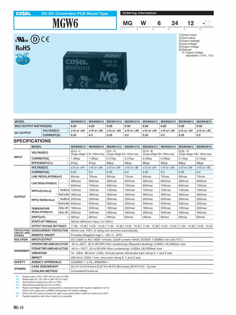
MGW6DC-DC Converters PCB Mount Type
MG W 6 24 12 -O
Ordering information
1 Series name2 Dual output3 Output wattage4 Input voltage5 Output voltage6 Optional Y2 : Output voltage adjustable (+10%, -5%)
R
1 2 3 4 5 6
MODEL MGW60512 MGW60515 MGW61212 MGW61215 MGW62412 MGW62415 MGW64812 MGW64815
MAX OUTPUT WATTAGE[W] 6.00 6.00 6.00 6.00 6.00 6.00 6.00 6.00
DC OUTPUT VOLTAGE[V] *1 ±12 or +24 ±15 or +30 ±12 or +24 ±15 or +30 ±12 or +24 ±15 or +30 ±12 or +24 ±15 or +30
CURRENT[A] 0.25 0.2 0.25 0.2 0.25 0.2 0.25 0.2
SPECIFICATIONSMODEL MGW60512 MGW60515 MGW61212 MGW61215 MGW62412 MGW62415 MGW64812 MGW64815
INPUT
VOLTAGE[V] DC4.5 - 9 (Surge voltage 12.5V, 100ms max)
DC9 - 18 (Surge voltage 25V, 100ms max)
DC18 - 36 (Surge voltage 50V, 100ms max)
DC36 - 76 (Surge voltage 100V, 100ms max)
CURRENT[A] *2 1.38typ 1.38typ 0.57typ 0.57typ 0.29typ 0.29typ 0.15typ 0.15typ
EFFICIENCY[%] *2 87typ 87typ 88typ 88typ 88typ 88typ 88typ 88typ
OUTPUT
VOLTAGE[V] ±12 or +24 ±15 or +30 ±12 or +24 ±15 or +30 ±12 or +24 ±15 or +30 ±12 or +24 ±15 or +30
CURRENT[A] 0.25 0.2 0.25 0.2 0.25 0.2 0.25 0.2
LINE REGULATION[mV] 60max 75max 60max 75max 60max 75max 60max 75max
LOAD REGULATION[mV]*3 480max 600max 480max 600max 480max 600max 480max 600max*4 600max 750max 600max 750max 600max 750max 600max 750max
RIPPLE[mVp-p]*5
Po=30% to 120max 120max 120max 120max 120max 120max 120max 120max
Po=0 to 30% 480max 480max 360max 360max 360max 360max 360max 360max
RIPPLE NOISE[mVp-p]*5
Po=30% to 200max 200max 200max 200max 200max 200max 200max 200max
Po=0 to 30% 600max 600max 500max 500max 500max 500max 500max 500max
TEMPERATURE REGULATION[mV]
-20 to +70C 180max 220max 180max 220max 180max 220max 180max 220max
-40 to +70C 290max 340max 290max 340max 290max 340max 290max 340max
DRIFT[mV] *6 48max 60max 48max 60max 48max 60max 48max 60max
START-UP TIME[ms] 30max (Minimum input, Io=100%)
OUTPUT VOLTAGE SETTING[V] 11.64 - 12.36 14.55 - 15.45 11.64 - 12.36 14.55 - 15.45 11.64 - 12.36 14.55 - 15.45 11.64 - 12.36 14.55 - 15.45
PROTECTION CIRCUIT AND OTHERS
OVERCURRENT PROTECTION Works over 105% of rating and recovers automatically
REMOTE ON/OFF Provided (Negative logic L : ON, H : OFF)
ISOLATION INPUT-OUTPUT DC1,500V or AC1,000V 1minute, Cutoff current=10mA, DC500V 1,000MW min (20±15C)
ENVIRONMENT
OPERATING TEMP.,HUMID.AND ALTITUDE -40 to +85C, 20 to 95%RH (Non condensing) (Required derating), 5,000m (16,400feet) max
STORAGE TEMP.,HUMID.AND ALTITUDE -40 to +100C, 20 to 95%RH (Non condensing), 9,000m (30,000feet) max
VIBRATION 10 - 55Hz 98.0m/s2 (10G), 3minute period, 60minutes each along X, Y and Z axis
IMPACT 490.3m/s2 (50G) 11ms, once each along X, Y and Z axis
SAFETY AGENCY APPROVALS UL60950-1, C-UL, EN60950-1
OTHERSCASE SIZE/WEIGHT 22.0X12.0X9.5mm [0.87X0.48X0.38 inches] (WXHXD) / 7g max
COOLING METHOD Convection/Forced air
*1 Single output +24V, +30V with no use of COM.*2 Rated input 5V, 12V, 24V or 48V DC Io=100%*3 Symmetrical loading from 20% to 100%.*4 Symmetrical loading from 0% to 100%.*5 Ripple and Ripple Noise is measured by using test board with ceramic capacitor 1 F at
50mm from output pins. (20MHz Osilloscope). Po:Output wattage.*6 Drift is the DC output accuracy for eight hours period after a half-hour warm-up at 25C.* Parallel operation with other model is not possible.
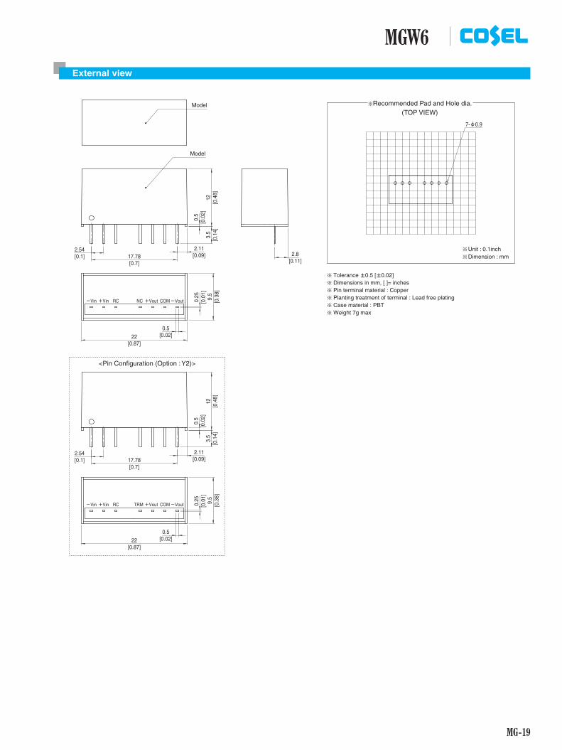
MG-19
MGW6External view
(TOP VIEW)¶Recommended Pad and Hole dia.
Model
Model
-Vin +Vin RC NC +Vout COM-Vout
2.112.5417.78 2.8
22
0.5
3.5
129.
5
0.5
0.25
¶¶
Unit : 0.1inchDimension : mm
¶ Tolerance ±0.5 [±0.02]¶ Dimensions in mm, [ ]= inches¶ Pin terminal material : Copper¶ Planting treatment of terminal : Lead free plating¶ Case material : PBT¶ Weight 7g max
[0.1
4]
[0.0
2]
[0.4
8][0
.38]
[0.0
1]
[0.11][0.09]
[0.7][0.1]
[0.02]
[0.87]
-Vin +Vin RC TRM +Vout COM-Vout
2.112.5417.78
22
0.5
3.5
129.
5
0.5
0.25
[0.1
4]
[0.0
2]
[0.4
8][0
.38]
[0.0
1]
[0.09][0.7]
[0.1]
[0.02]
[0.87]
<Pin Configuration (Option : Y2)>
7-f0.9

MG-20
MGW10DC-DC Converters PCB Mount Type
MG W 10 24 12 -O
Ordering information
1 Series name2 Dual output3 Output wattage4 Input voltage5 Output voltage6 Optional Y2 : Output voltage adjustable (+10%, -5%)
R
1 2 3 4 5 6
MODEL MGW100512 MGW100515 MGW101212 MGW101215 MGW102412 MGW102415 MGW104812 MGW104815
MAX OUTPUT WATTAGE[W] 10.08 10.20 10.08 10.20 10.08 10.20 10.08 10.20
DC OUTPUT VOLTAGE[V] *1 ±12 or +24 ±15 or +30 ±12 or +24 ±15 or +30 ±12 or +24 ±15 or +30 ±12 or +24 ±15 or +30
CURRENT[A] 0.42 0.34 0.42 0.34 0.42 0.34 0.42 0.34
SPECIFICATIONSMODEL MGW100512 MGW100515 MGW101212 MGW101215 MGW102412 MGW102415 MGW104812 MGW104815
INPUT
VOLTAGE[V] DC4.5 - 9 (Surge voltage 12.5V, 100ms max)
DC9 - 18 (Surge voltage 25V, 100ms max)
DC18 - 36 (Surge voltage 50V, 100ms max)
DC36 - 76 (Surge voltage 100V, 100ms max)
CURRENT[A] *2 2.38typ 2.40typ 0.97typ 0.97typ 0.49typ 0.49typ 0.24typ 0.25typ
EFFICIENCY[%] *2 85typ 85typ 87typ 88typ 87typ 88typ 88typ 88typ
OUTPUT
VOLTAGE[V] ±12 or +24 ±15 or +30 ±12 or +24 ±15 or +30 ±12 or +24 ±15 or +30 ±12 or +24 ±15 or +30
CURRENT[A] 0.42 0.34 0.42 0.34 0.42 0.34 0.42 0.34
LINE REGULATION[mV] 60max 75max 60max 75max 60max 75max 60max 75max
LOAD REGULATION[mV]*3 480max 600max 480max 600max 480max 600max 480max 600max*4 600max 750max 600max 750max 600max 750max 600max 750max
RIPPLE[mVp-p]*5
Po=30% to 120max 120max 120max 120max 120max 120max 120max 120max
Po=0 to 30% 480max 480max 360max 360max 360max 360max 360max 360max
RIPPLE NOISE[mVp-p]*5
Po=30% to 200max 200max 200max 200max 200max 200max 200max 200max
Po=0 to 30% 600max 600max 500max 500max 500max 500max 500max 500max
TEMPERATURE REGULATION[mV]
-20 to +50C 150max 180max 150max 180max 150max 180max 150max 180max
-40 to +50C 240max 290max 240max 290max 240max 290max 240max 290max
DRIFT[mV] *6 48max 60max 48max 60max 48max 60max 48max 60max
START-UP TIME[ms] 30max (Minimum input, Io=100%)
OUTPUT VOLTAGE SETTING[V] 11.64 - 12.36 14.55 - 15.45 11.64 - 12.36 14.55 - 15.45 11.64 - 12.36 14.55 - 15.45 11.64 - 12.36 14.55 - 15.45
PROTECTION CIRCUIT AND OTHERS
OVERCURRENT PROTECTION Works over 105% of rating and recovers automatically
REMOTE ON/OFF Provided (Negative logic L : ON, H : OFF)
ISOLATION INPUT-OUTPUT DC1,500V or AC1,000V 1minute, Cutoff current=10mA, DC500V 1,000MW min (20±15C)
ENVIRONMENT
OPERATING TEMP.,HUMID.AND ALTITUDE -40 to +85C, 20 to 95%RH (Non condensing) (Required derating), 5,000m (16,400feet) max
STORAGE TEMP.,HUMID.AND ALTITUDE -40 to +100C, 20 to 95%RH (Non condensing), 9,000m (30,000feet) max
VIBRATION 10 - 55Hz 98.0m/s2 (10G), 3minute period, 60minutes each along X, Y and Z axis
IMPACT 490.3m/s2 (50G) 11ms, once each along X, Y and Z axis
SAFETY AGENCY APPROVALS UL60950-1, C-UL, EN60950-1
OTHERSCASE SIZE/WEIGHT 22.0X12.0X9.5mm [0.87X0.48X0.38 inches] (WXHXD) / 7g max
COOLING METHOD Convection/Forced air
*1 Single output +24V, +30V with no use of COM.*2 Rated input 5V, 12V, 24V or 48V DC Io=100%*3 Symmetrical loading from 20% to 100%.*4 Symmetrical loading from 0% to 100%.*5 Ripple and Ripple Noise is measured by using test board with ceramic capacitor 1 F at
50mm from output pins. (20MHz Osilloscope). Po:Output wattage.*6 Drift is the DC output accuracy for eight hours period after a half-hour warm-up at 25C.* Parallel operation with other model is not possible.

MG-21
MGW10External view
(TOP VIEW)¶Recommended Pad and Hole dia.
-Vin +Vin RC NC +Vout
2.112.5417.78 2.8
22
0.5
3.5
129.
5
0.5
0.25
¶¶
Unit : 0.1inchDimension : mm
¶ Tolerance ±0.5 [±0.02]¶ Dimensions in mm, [ ]= inches¶ Pin terminal material : Copper¶ Planting treatment of terminal : Lead free plating¶ Case material : PBT¶ Weight 7g max
[0.1
4]
[0.0
2]
[0.4
8][0
.38]
[0.0
1]
[0.11][0.09]
[0.7][0.1]
[0.02]
[0.87]
Model
Model
COM-Vout
-Vin +Vin RC TRM+Vout
2.112.5417.78
22
0.5
3.5
129.
5
0.5
0.25
[0.1
4]
[0.0
2]
[0.4
8][0
.38]
[0.0
1]
[0.09][0.7]
[0.1]
[0.02]
[0.87]
COM-Vout
<Pin Configuration (Option : Y2)>
7-f0.9
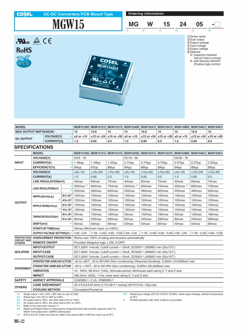
MG-22
MGW15DC-DC Converters PCB Mount Type
MG W 15 24 05 -O
Ordering information
1 Series name2 Dual output3 Output wattage4 Input voltage5 Output voltage6 Optional G : Capacitor between Input and Output is removed. R : with Remote ON/OFF (Positive logic control)
R
1 2 3 4 5 6
MODEL MGW151205 MGW151212 MGW151215 MGW152405 MGW152412 MGW152415 MGW154805 MGW154812 MGW154815
MAX OUTPUT WATTAGE[W] 15 15.6 15 15 15.6 15 15 15.6 15
DC OUTPUT VOLTAGE[V] *1 ±5 or +10 ±12 or +24 ±15 or +30 ±5 or +10 ±12 or +24 ±15 or +30 ±5 or +10 ±12 or +24 ±15 or +30
CURRENT[A] 1.5 0.65 0.5 1.5 0.65 0.5 1.5 0.65 0.5
SPECIFICATIONSMODEL MGW151205 MGW151212 MGW151215 MGW152405 MGW152412 MGW152415 MGW154805 MGW154812 MGW154815
INPUT
VOLTAGE[V] DC9 - 18 DC18 - 36 DC36 - 76
CURRENT[A] *2 1.48typ 1.49typ 1.42typ 0.74typ 0.74typ 0.70typ 0.37typ 0.37typ 0.35typ
EFFICIENCY[%] *2 84typ 87typ 88typ 84typ 88typ 89typ 84typ 89typ 89typ
OUTPUT
VOLTAGE[V] ±5(+10) ±12(+24) ±15(+30) ±5(+10) ±12(+24) ±15(+30) ±5(+10) ±12(+24) ±15(+30)
CURRENT[A] 1.5 0.65 0.5 1.5 0.65 0.5 1.5 0.65 0.5
LINE REGULATION[mV] 40max 60max 75max 40max 60max 75max 40max 60max 75max
LOAD REGULATION[mV]*3 500max *5 600max 750max 500max *5 600max 750max 500max *5 600max 750max*4 250max 480max 600max 250max 480max 600max 250max 480max 600max
RIPPLE[mVp-p]*6
-20 to +60C 100max 100max 100max 100max 100max 100max 100max 100max 100max
-40 to -20C 120max 120max 120max 120max 120max 120max 120max 120max 120max
RIPPLE NOISE[mVp-p]*6
-20 to +60C 100max 100max 100max 100max 100max 100max 100max 100max 100max
-40 to -20C 150max 150max 150max 150max 150max 150max 150max 150max 150max
TEMPERATURE REGULATION[mV]-20 to +60C 50max 150max 180max 50max 150max 180max 50max 150max 180max
-40 to +60C 80max 240max 290max 80max 240max 290max 80max 240max 290max
DRIFT[mV] *7 50max 50max 60max 50max 50max 60max 50max 50max 60max
START-UP TIME[ms] 30max (Minimum input, Io=100%)
OUTPUT VOLTAGE SETTING[V]*8 4.935 - 5.240 11.765 - 12.492 14.602 - 15.505 4.935 - 5.240 11.765 - 12.492 14.602 - 15.505 4.935 - 5.240 11.765 - 12.492 14.602 - 15.505
PROTECTION CIRCUIT AND OTHERS
OVERCURRENT PROTECTION Works over 105% of rating and recovers automatically
REMOTE ON/OFF Provided (Negative logic L:ON, H:OFF)
ISOLATION
INPUT-OUTPUT DC1,500V 1minute, Cutoff current = 10mA, DC500V 1,000MW min (20±15C)
INPUT-CASE DC1,000V 1minute, Cutoff current = 10mA, DC500V 1,000MW min (20±15C)
OUTPUT-CASE DC1,000V 1minute, Cutoff current = 10mA, DC500V 1,000MW min (20±15C)
ENVIRONMENT
OPERATING TEMP.,HUMID.AND ALTITUDE -40 to +85C, 20 to 95%RH (Non condensing) (Required Derating), 3,000m (10,000feet) max
STORAGE TEMP.,HUMID.AND ALTITUDE -40 to +100C, 20 to 95%RH (Non condensing), 9,000m (30,000feet) max
VIBRATION 10 - 55Hz, 98.0m/s2 (10G), 3minutes period, 60minutes each along X, Y and Z axis
IMPACT 490.3m/s2 (50G), 11ms, once each along X, Y and Z axis
SAFETY AGENCY APPROVALS UL60950-1, C-UL, EN60950-1
OTHERSCASE SIZE/WEIGHT 25.4X9.9X25.4mm [1X0.39X1 inches] (WXHXD) / 20g max
COOLING METHOD Convection/Forced air
*1 Single output +10V, +24V, +30V with no use of COM.*2 Rated input 12V, 24V or 48V lo=100%*3 An output load is 100%, the other load is 5% to 100%.*4 An output load is 100%, the other load is 20% to 100%.*5 Refer to the instruction manual 11.*6 Ripple and Ripple Noise is measured by using test board with ceramic capacitor 22 F at
50mm from output pins. (20MHz Osilloscope)*7 Drift is the DC output accuracy for eight hours period after a half-hour warm-up at 25C.
*8 Rated input voltage (DC12V, DC24V, DC48V), rated output wattage, ambient temperature at 25C.
* Parallel operation with other model is not possible.
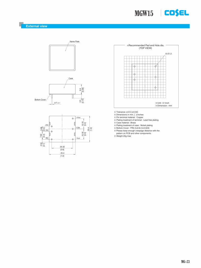
MG-23
MGW15External view
(TOP VIEW)¶Recommended Pad and Hole dia.
1±0.1f 3.5
9.9
6-f1.5
Name Plate
¶ Tolerance ±0.5 [±0.02]¶ Dimensions in mm, [ ]=inches¶ Pin terminal material : Copper¶ Plating treatment of terminal : Lead free plating¶ Case material : Brass¶ Plating treatment of case : Nickel plating¶ Bottom Cover : FR4 (t=0.6) [t=0.024]¶ Please keep enough creepage distance with the pattern on PCB and other components.¶ Weight 20g max
¶¶
Unit : 0.1inchDimension : mm
[0.8]
[1.0]
[0.1
][0
.3]
[0.2
]
[0.4
][0
.4]
[0.1
4][0
.39]
[1.0
]
+Vin
-Vin
RC
+Vout
-Vout
COM
10.1
6
25.4
20.32
2.54
25.4
5.08
7.62
10.1
6
Case
Bottom Cover

MG-24
MGW30DC-DC Converters PCB Mount Type
MG W 30 24 05 -O
Ordering information
1 Series name2 Dual output3 Output wattage4 Input voltage5 Output voltage6 Optional G : Capacitor between Input and Output is removed. R : with Remote ON/OFF (Positive logic control)
R
1 2 3 4 5 6
MODEL MGW301205 MGW301212 MGW301215 MGW302405 MGW302412 MGW302415 MGW304805 MGW304812 MGW304815
MAX OUTPUT WATTAGE[W] 25 30 30 25 30 30 25 30 30
DC OUTPUT VOLTAGE[V] *1 ±5 or +10 ±12 or +24 ±15 or +30 ±5 or +10 ±12 or +24 ±15 or +30 ±5 or +10 ±12 or +24 ±15 or +30
CURRENT[A] 2.5 1.25 1 2.5 1.25 1 2.5 1.25 1
SPECIFICATIONSMODEL MGW301205 MGW301212 MGW301215 MGW302405 MGW302412 MGW302415 MGW304805 MGW304812 MGW304815
INPUT
VOLTAGE[V] DC9 - 18 DC18 - 36 DC36 - 76
CURRENT[A] *2 2.42typ 2.78typ 2.78typ 1.20typ 1.38typ 1.38typ 0.60typ 0.70typ 0.70typ
EFFICIENCY[%] *2 86typ 90typ 90typ 87typ 91typ 91typ 87typ 90typ 90typ
OUTPUT
VOLTAGE[V] ±5(+10) ±12(+24) ±15(+30) ±5(+10) ±12(+24) ±15(+30) ±5(+10) ±12(+24) ±15(+30)
CURRENT[A] 2.5 1.25 1 2.5 1.25 1 2.5 1.25 1
LINE REGULATION[mV] 40max 60max 75max 40max 60max 75max 40max 60max 75max
LOAD REGULATION[mV]*3 500max *5 600max 750max 500max *5 600max 750max 500max *5 600max 750max*4 250max 480max 600max 250max 480max 600max 250max 480max 600max
RIPPLE[mVp-p]*6
-20 to +60C 100max 100max 100max 100max 100max 100max 100max 100max 100max
-40 to -20C 120max 120max 120max 120max 120max 120max 120max 120max 120max
RIPPLE NOISE[mVp-p]*6
-20 to +60C 100max 100max 100max 100max 100max 100max 100max 100max 100max
-40 to -20C 150max 150max 150max 150max 150max 150max 150max 150max 150max
TEMPERATURE REGULATION[mV]-20 to +60C 50max 150max 180max 50max 150max 180max 50max 150max 180max
-40 to +60C 80max 240max 290max 80max 240max 290max 80max 240max 290max
DRIFT[mV] *7 50max 50max 60max 50max 50max 60max 50max 50max 60max
START-UP TIME[ms] 30max (Minimum input, Io=100%)
OUTPUT VOLTAGE SETTING[V]*8 4.935 - 5.240 11.765 - 12.492 14.602 - 15.505 4.935 - 5.240 11.765 - 12.492 14.602 - 15.505 4.935 - 5.240 11.765 - 12.492 14.602 - 15.505
PROTECTION CIRCUIT AND OTHERS
OVERCURRENT PROTECTION Works over 105% of rating and recovers automatically
OVERVOLTAGE PROTECTION[V] Works over 120 to 160% of rating (Total of +V and -V)
REMOTE ON/OFF Provided (Negative logic L:ON, H:OFF)
ISOLATION
INPUT-OUTPUT DC1,500V 1minute, Cutoff current = 10mA, DC500V 1,000MW min (20±15C)
INPUT-CASE DC1,000V 1minute, Cutoff current = 10mA, DC500V 1,000MW min (20±15C)
OUTPUT-CASE DC1,000V 1minute, Cutoff current = 10mA, DC500V 1,000MW min (20±15C)
ENVIRONMENT
OPERATING TEMP.,HUMID.AND ALTITUDE -40 to +85C, 20 to 95%RH (Non condensing) (Required Derating), 3,000m (10,000feet) max
STORAGE TEMP.,HUMID.AND ALTITUDE -40 to +100C, 20 to 95%RH (Non condensing), 9,000m (30,000feet) max
VIBRATION 10 - 55Hz, 98.0m/s2 (10G), 3minutes period, 60minutes each along X, Y and Z axis
IMPACT 490.3m/s2 (50G), 11ms, once each along X, Y and Z axis
SAFETY AGENCY APPROVALS UL60950-1, C-UL, EN60950-1
OTHERSCASE SIZE/WEIGHT 25.4X9.9X50.8mm [1X0.39X2 inches] (WXHXD) / 40g max
COOLING METHOD Convection/Forced air*1 Single output +10V, +24V, +30V with no use of COM.*2 Rated input 12V, 24V or 48V DC lo=100%*3 Symmetrical loading from 5% to 100%.*4 Symmetrical loading from 20% to 100%.*5 Refer to the instruction manual 11.*6 Ripple and Ripple Noise is measured by using test board with ceramic capacitor 22 F at
50mm from output pins. (20MHz Osilloscope)
*7 Drift is the DC output accuracy for eight hours period after a half-hour warm-up at 25C.*8 Rated input voltage (DC12V, DC24V, DC48V), rated output wattage, ambient temperature
at 25C.* Parallel operation with other model is not possible.

MG-25
MGW30External view
(TOP VIEW)¶Recommended Pad and Hole dia.
¶ Tolerance ±0.5 [±0.02]¶ Dimensions in mm, [ ]=inches¶ Pin terminal material : Copper¶ Plating treatment of terminal : Lead free plating¶ Case material : Brass¶ Plating treatment of case : Nickel plating¶ Bottom Cover : FR4 (t=0.6) [t=0.024]¶ Please keep enough creepage distance with the pattern on PCB and other components.¶ Weight 40g max
9.9
3.5
1±0.1f
6-f1.5
Name Plate
+Vout
COM
-Vout
+Vin
-Vin
RC
10.1
610
.16
5.08
10.1
65.
08
25.4
45.72
50.8
¶¶
Unit : 0.1inchDimension : mm
Case
Bottom Cover
[1.8]
[2.0]
[0.2
][0
.4]
[0.2
]
[0.4
][0
.4]
[0.1
4][0
.39]
[1.0
]