DATE: PROJECT: TO: FROM: SUBJECT: HILTI X-CW CEILING WIRE … · 2017-08-16 · Hilti X-CW Ceiling...
14
Hilti, Inc. 5400 South 122 nd East Avenue Tulsa, OK 74146 1-800-879-8000 www.us.hilti.com DATE: PROJECT: TO: FROM: SUBJECT: HILTI X-CW CEILING WIRE FASTENER SUBSTITUTION REQUEST SPECIFICATION TITLE: SECTION: PAGE: ARTICLE/PARAGRAPH: DESCRIPTION: DESIGN DETAIL NO.: PROPOSED SUBSTITUTION: Use HILTI X-CW Ceiling Wire for Suspended Ceiling Systems PRODUCT DESCRIPTION: The Hilti X-CW Ceiling Wire Fastening Assembly consists of a pre- mounted powder-actuated fastener, either X-U or X-C type, with a pre-mounted 0.06 in. (1.5 mm) thick steel clamping washer and a 12 gauge (0.106in/2.7 mm) diameter galvanized, soft annealed mild carbon steel wire for supporting direct and indirect suspended lay-in panel ceilings. SUBMITTED BY: SUPPORTING DATA ATTACHED: A/E REVIEW AND ACTION: □ 2009 SUPPLEMENT TO HILTI PRODUCT TECHNICAL GUIDE, 2008 □ SUBSTITUTUTION APPROVED □ ICC EVALUATION SERVICE REPORT ESR-2892 □ SUBSTITUTION APPROVED AS NOTED □ FASTENER LOAD COMPARISONS □ SUBSTITUTION REJECTED □ SAMPLES □ PRICING INFORMATION COMMENTS: SIGNED BY: DATE:
Transcript of DATE: PROJECT: TO: FROM: SUBJECT: HILTI X-CW CEILING WIRE … · 2017-08-16 · Hilti X-CW Ceiling...
Hilti, Inc.
5400 South 122nd East Avenue Tulsa, OK 74146
1-800-879-8000
www.us.hilti.com
DATE: PROJECT: TO: FROM: SUBJECT: HILTI X-CW CEILING WIRE FASTENER SUBSTITUTION REQUEST
SPECIFICATION TITLE: SECTION: PAGE: ARTICLE/PARAGRAPH: DESCRIPTION: DESIGN DETAIL NO.: PROPOSED SUBSTITUTION: Use HILTI X-CW Ceiling Wire for Suspended Ceiling Systems
PRODUCT DESCRIPTION: The Hilti X-CW Ceiling Wire Fastening Assembly consists of a pre-mounted powder-actuated fastener, either X-U or X-C type, with a pre-mounted 0.06 in. (1.5 mm) thick steel clamping washer and a 12 gauge (0.106in/2.7 mm) diameter galvanized, soft annealed mild carbon steel wire for supporting direct and indirect suspended lay-in panel ceilings.
SUBMITTED BY:
SUPPORTING DATA ATTACHED: A/E REVIEW AND ACTION: □ 2009 SUPPLEMENT TO HILTI PRODUCT TECHNICAL GUIDE, 2008 □ SUBSTITUTUTION APPROVED □ ICC EVALUATION SERVICE REPORT ESR-2892 □ SUBSTITUTION APPROVED AS NOTED □ FASTENER LOAD COMPARISONS □ SUBSTITUTION REJECTED □ SAMPLES □ PRICING INFORMATION
COMMENTS: SIGNED BY:
DATE:
Hilti, Inc. 5400 South 122nd East Avenue
Tulsa, OK 74146
1-800-879-8000 www.hilti.com
October 23, 2009 Subject: IBC / IRC Compliance of Hilti X-CW Ceiling Wire Assemblies (ICC-ES ESR-2892) To Whom It May Concern: This memorandum addresses the 2006 IBC (International Building Code) and IRC (International Residential Code) compliance of Hilti X-CW Ceiling Wire Assemblies. Hilti X-CW Ceiling Wire Assemblies consist of a pre-mounted Hilti powder-actuated fastener, X-U (ICC-ES ESR-2269) or X-C (ICC-ES ESR-1663) type, with a pre-mounted clamping washer and a 12 gauge soft annealed mild carbon steel wire for supporting direct and indirect hung suspended lay-in panel ceilings. Hilti X-CW Ceiling Wire Assemblies have been tested and evaluated by ICC-ES in accordance with AC70-07, Acceptance Criteria for Fasteners Power-Driven into Concrete, Steel, and Masonry Elements in order to provide recognition under 2006 IBC and IRC. Hilti X-CW Ceiling Wire Assemblies are recognized in evaluation service report ESR-2892 issued by ICC-ES, and meet the OSHPD and DSA requirements for fastening of acoustical lay-in panel suspended ceiling systems, subject to the conditions of OSHPD CAN 2-1912A.1 and DSA IR 25-2. X-CW Ceiling Wire Assemblies are an alternative method of fastening for acoustical suspended ceiling systems as referenced in ASTM C635, which is referenced in Section 809.3 of 2006 IBC, and may be substituted for Hilti X-CC type Ceiling Clips (ICC-ES ESR-2184) if allowable service load requirements are satisfied. For additional information or inquiries, please contact Hilti Technical Services at [email protected] or call 1-800-749-6337. Regards,
William G. Gould, P.E. Director, Codes and Approvals Hilti, Inc. (800) 879-6000 x-7804 [email protected] Ref. ICC-ES AC70 Acceptance Criteria for Concrete, Steel and Masonry Elements, 1-1-07
OSHPD CAN 2-1912A.1 Qualification, Design and Use of Anchors Installed in Concrete, 7-1-08 DSA IR 25-2 Metal Suspension Systems for Lay-In Panel Ceilings, 7-21-05
ICC-ES Evaluation Reports are not to be construed as representing aesthetics or any other attributes not specifically addressed, nor are they to be construed as an endorsement of the subject of the report or a recommendation for its use. There is no warranty by ICC Evaluation Service, Inc., express or implied, as to any finding or other matter in this report, or as to any product covered by the report.
Copyright © 2009 Page 1 of 4
ICC-ES Evaluation Report ESR-2892 Issued October 1, 2009 This report is subject to re-examination in one year.
www.icc-es.org | (800) 423-6587 | (562) 699-0543 A Subsidiary of the International Code Council ®
DIVISION: 03—CONCRETE Section: 03151—Concrete Anchoring DIVISION: 09—FINISHES Section: 09051—Fasteners REPORT HOLDER:
HILTI, INC. 5400 SOUTH 122ND EAST AVENUE TULSA, OKLAHOMA 74146 (800) 879-8000 www.us.hilti.com EVALUATION SUBJECT HILTI X-CW CEILING WIRE ASSEMBLIES 1.0 EVALUATION SCOPE
Compliance with the following codes: # 2006 International Building Code® (IBC)
# 2006 International Residential Code® (IRC)
# 2003 International Building Code® (2003 IBC)*
# 2003 International Residential Code® (2003 IRC)*
# 2000 International Building Code® (2000 IBC)*
# 2000 International Residential Code® (2000 IRC)*
# 1997 Uniform Building Code™ (UBC)*
*Codes indicated with an asterisk are addressed in Section 8.0.
Property evaluated Structural
2.0 USES Hilti X-CW ceiling wire assemblies are used to fasten steel wire to normal-weight concrete and structural sand-lightweight concrete filled metal deck for the purpose of hanging suspended ceiling systems complying with IBC Section 803.9. The fasteners may be used where an engineered design is submitted in accordance with IRC Section R301.1.3.
3.0 DESCRIPTION 3.1 General: The Hilti X-CW Ceiling Wire Assembly consists of a steel wire clamped to a powder-actuated fastener with a premounted clamping washer, as shown in Figure 1. See Table 1 for assembly types and fastener dimensions.
3.2 Powder-actuated fastener:
The powder-actuated fasteners used in the X-CW assemblies are the Hilti X-C and X-U fasteners, recognized in ESR-1663 and ESR-2269, respectively.
3.3 Clamping Washer: The premounted clamping washer is formed from steel complying with ASTM A 653M SS, Grade 255, with a Z120 coating designation. The steel has a base-metal thickness of 0.06 inch (1.5 mm).
3.4 Wire: The ceiling wire is No. 12 gage [0.106 inch (2.7 mm)] diameter, zinc-coated carbon steel wire complying with ASTM A 641, soft temper, with a Class 1 zinc coating designation.
4.0 DESIGN AND INSTALLATION 4.1 Design: The allowable tension and 45-degree-angle loads for X-CW ceiling wire assemblies installed into normal-weight concrete are provided in Table 2. The allowable tension and 45-degree-angle loads for X-CW ceiling wire assemblies installed through metal deck into structural sand-lightweight concrete are provided in Table 3. For installation at angles between 45 degrees and 90 degrees to the supporting slab, the allowable load is the lesser of the allowable tension and 45-degree-angle loads.
The stress increases described in Section 1605.3 of the IBC are not allowed for wind loads acting alone or when combined with vertical loads. No increase is allowed for vertical loads acting alone. Use of fasteners to resist earthquake loads is outside the scope of this report.
4.2 Installation: 4.2.1 General: The X-CW ceiling wire assemblies must be installed in accordance with this report and the manufacturer’s published installation instructions, including those shown in Figure 2. A copy of these instructions must be available on the jobsite at all times during installation. Installation must be limited to dry, interior locations.
Fastener placement requires the use of a low-velocity powder-actuated tool in accordance with Hilti recommendations. Fastener standoff distance must be as noted in the footnotes to the tables and as shown in Figure 2. Installers must be certified by Hilti.
4.2.2 Fastening to Concrete: Fasteners must be driven into the concrete after the concrete attains the specified concrete compressive strength. Minimum spacing between fasteners must be 4 inches (102 mm) and minimum edge
ESR-2892 | Most Widely Accepted and Trusted Page 2 of 4
distance must be 3 inches (76 mm). Unless otherwise noted in this report, concrete thickness must be a minimum of three times the embedment depth of the fastener.
4.2.3 Fastening to Structural Sand-lightweight Concrete Filled Steel Deck: Installation in structural sand-lightweight concrete filled steel deck must comply with Figure 3. Minimum distance from fastener centerline to rolled deck flute edges must be as depicted in Figure 3.
5.0 CONDITIONS OF USE
The Hilti X-CW ceiling wire assemblies described in this report comply with, or are suitable alternatives to what is specified in, those codes listed in Section 1.0 of this report, subject to the following conditions:
5.1 The fasteners are manufactured and identified in accordance with this report.
5.2 Fastener installation complies with this report and the Hilti, Inc., instructions. In the event of conflict between this report and Hilti, Inc., published instructions, this report governs.
5.3 Allowable tension and 45-degree values are as noted in Tables 2 and 3. The stress increases and load reductions described in Section 1605.3.2 of the IBC are not allowed for wind loads acting alone or when combined with gravity loads. No increase is allowed for vertical loads acting alone.
5.4 Calculations demonstrating that the applied loads are less than the allowable loads described in this report must be submitted to the code official for approval. The calculations must be prepared by a registered design professional where required by the statutes of the jurisdiction in which the project is constructed.
5.5 Use of fasteners to resist earthquake loads is outside the scope of this report.
5.6 The use of fasteners is limited to installation in uncracked concrete. Cracking occurs when ft > fr due to service loads or deformations.
5.7 Use of fasteners is limited to dry, interior locations.
5.8 Installers must be certified by Hilti and have a current, Hilti-issued, operator’s license.
6.0 EVIDENCE SUBMITTED
6.1 Data in accordance with the ICC-ES Acceptance Criteria for Fasteners Power-driven into Concrete, Steel and Masonry Elements (AC70), dated October 2006.
6.2 Report of testing of hanger wire connection to fastener, in accordance with the ICC-ES Acceptance Criteria for Suspended Ceiling Framing Systems (AC368), dated February 2007.
7.0 IDENTIFICATION The fasteners are imprinted with an “H” on the head. All assemblies are identified on the packaging with the Hilti, Inc., name, the fastener type and size, and the evaluation report number (ESR-2892).
8.0 OTHER CODES 8.1 Evaluation Scope: In addition to the codes referenced in Section 1.0, the products in this report were evaluated for compliance with the requirements of the following codes:
# 2003 International Building Code® (2003 IBC)
# 2003 International Residential Code® (2003 IRC)
# 2000 International Building Code® (2000 IBC)
# 2000 International Residential Code® (2000 IRC)
# 1997 Uniform Building Code™ (UBC)
8.1 Uses: See Section 2.0. The fasteners may be used where an engineered design is submitted in accordance with 2003 IRC Section R301.1.3 or 2000 IRC Section R301.1.2, as applicable. 8.2 Description: See Section 3.0.
8.3 Design and Installation: 8.3.1 Design: See Section 4.1 and the following:
The stress increases described in Section 1612.3.2 of the UBC are not allowed for wind loads acting alone or when combined with gravity loads. Use of fasteners to resist earthquake loads is outside the scope of this report. 8.3.2 Installation: See Section 4.2.
8.4 Conditions of use: See Section 5.0.
8.5 Evidence Submitted: See Section 6.0.
8.6 Identification: See Section 7.0.
ESR-2892 | Most Widely Accepted and Trusted Page 3 of 4
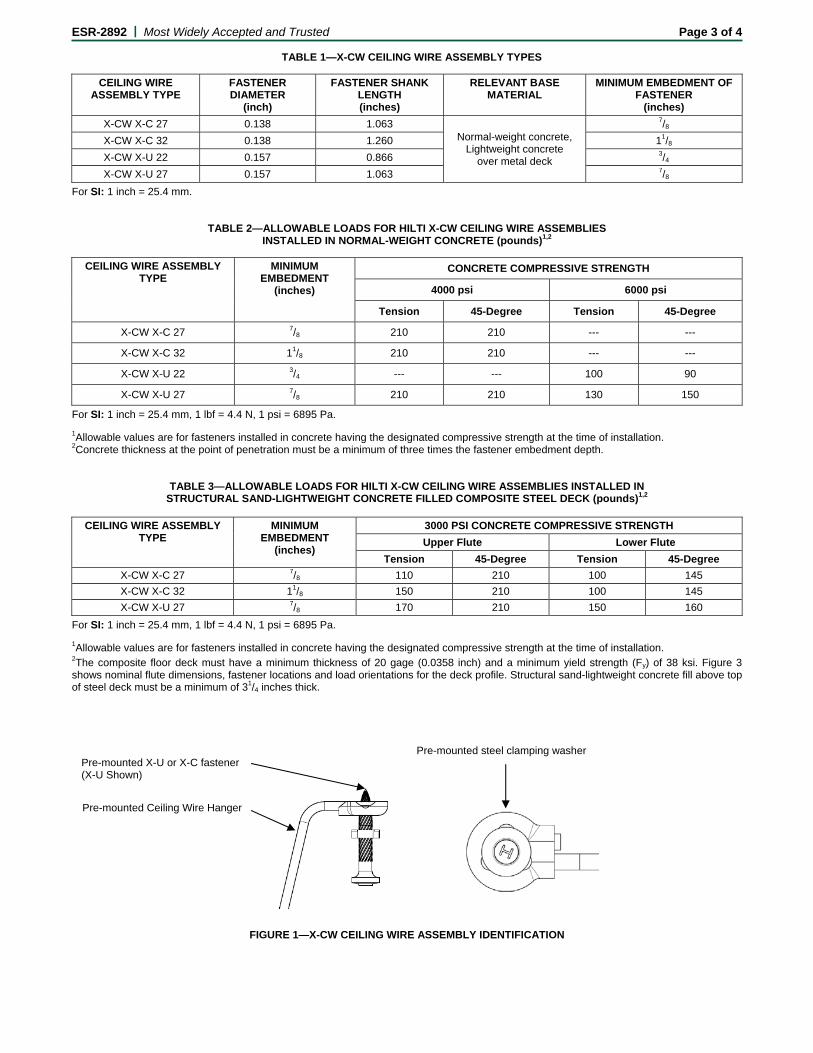
TABLE 1—X-CW CEILING WIRE ASSEMBLY TYPES
CEILING WIRE ASSEMBLY TYPE
FASTENER DIAMETER
(inch)
FASTENER SHANK LENGTH (inches)
RELEVANT BASE MATERIAL
MINIMUM EMBEDMENT OF FASTENER
(inches) X-CW X-C 27 0.138 1.063
Normal-weight concrete, Lightweight concrete
over metal deck
7/8 X-CW X-C 32 0.138 1.260 11/8 X-CW X-U 22 0.157 0.866 3/4 X-CW X-U 27 0.157 1.063 7/8
For SI: 1 inch = 25.4 mm.
TABLE 2—ALLOWABLE LOADS FOR HILTI X-CW CEILING WIRE ASSEMBLIES INSTALLED IN NORMAL-WEIGHT CONCRETE (pounds)1,2
CEILING WIRE ASSEMBLY TYPE
MINIMUM EMBEDMENT
(inches)
CONCRETE COMPRESSIVE STRENGTH
4000 psi 6000 psi
Tension 45-Degree Tension 45-Degree
X-CW X-C 27 7/8 210 210 --- ---
X-CW X-C 32 11/8 210 210 --- ---
X-CW X-U 22 3/4 --- --- 100 90
X-CW X-U 27 7/8 210 210 130 150
For SI: 1 inch = 25.4 mm, 1 lbf = 4.4 N, 1 psi = 6895 Pa. 1Allowable values are for fasteners installed in concrete having the designated compressive strength at the time of installation. 2Concrete thickness at the point of penetration must be a minimum of three times the fastener embedment depth.
TABLE 3—ALLOWABLE LOADS FOR HILTI X-CW CEILING WIRE ASSEMBLIES INSTALLED IN STRUCTURAL SAND-LIGHTWEIGHT CONCRETE FILLED COMPOSITE STEEL DECK (pounds)1,2
CEILING WIRE ASSEMBLY
TYPE MINIMUM
EMBEDMENT (inches)
3000 PSI CONCRETE COMPRESSIVE STRENGTH Upper Flute Lower Flute
Tension 45-Degree Tension 45-Degree X-CW X-C 27 7/8 110 210 100 145 X-CW X-C 32 11/8 150 210 100 145 X-CW X-U 27 7/8 170 210 150 160
For SI: 1 inch = 25.4 mm, 1 lbf = 4.4 N, 1 psi = 6895 Pa. 1Allowable values are for fasteners installed in concrete having the designated compressive strength at the time of installation. 2The composite floor deck must have a minimum thickness of 20 gage (0.0358 inch) and a minimum yield strength (Fy) of 38 ksi. Figure 3 shows nominal flute dimensions, fastener locations and load orientations for the deck profile. Structural sand-lightweight concrete fill above top of steel deck must be a minimum of 31/4 inches thick.
FIGURE 1—X-CW CEILING WIRE ASSEMBLY IDENTIFICATION
Pre-mounted X-U or X-C fastener (X-U Shown)
Pre-mounted Ceiling Wire Hanger
Pre-mounted steel clamping washer
ESR-2892 | Most Widely Accepted and Trusted Page 4 of 4
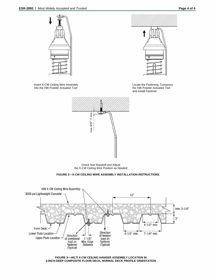
Insert X-CW Ceiling Wire Assembly Locate the Fastening, Compress
Into the Hilti Powder Actuated Tool the Hilti Powder-Actuated Tool and Install Fastener
Check Nail Standoff and Adjust the X-CW Ceiling Wire Position as Needed
FIGURE 2—X-CW CEILING WIRE ASSEMBLY INSTALLATION INSTRUCTIONS
FIGURE 3—HILTI X-CW CEILING HANGER ASSEMBLY LOCATION IN
3-INCH-DEEP COMPOSITE FLOOR DECK, NORMAL DECK PROFILE ORIENTATION
X-CWCeiling WireFastening Assemblies
2009 Supplement toHilti North AmericanProduct Technical Guide,2008 Edition
2009 Edition
Direct Fastening Systems
Hilti X-CW Ceiling Wire Assembly
Hilti, Inc. (US) 1-800-879-8000 | www.us.hilti.com I en español 1-800-879-5000 I Hilti (Canada) Corp. 1-800-363-4458 I www.hilti.ca I X-CW Supplement 2009 1
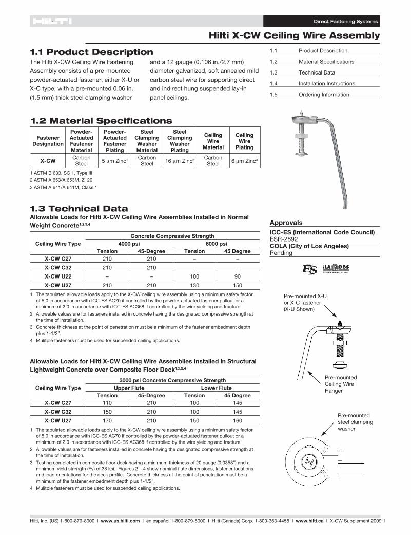
1.1 Product DescriptionThe Hilti X-CW Ceiling Wire Fastening Assembly consists of a pre-mounted powder-actuated fastener, either X-U or X-C type, with a pre-mounted 0.06 in. (1.5 mm) thick steel clamping washer
and a 12 gauge (0.106 in./2.7 mm) diameter galvanized, soft annealed mild carbon steel wire for supporting direct and indirect hung suspended lay-in panel ceilings.
1.1 Product Description
1.2 Material Specifications
1.3 Technical Data
1.4 Installation Instructions
1.5 Ordering Information
ApprovalsICC-ES (International Code Council) ESR-2892COLA (City of Los Angeles) Pending
1.3 Technical Data
1 The tabulated allowable loads apply to the X-CW ceiling wire assembly using a minimum safety factor of 5.0 in accordance with ICC-ES AC70 if controlled by the powder-actuated fastener pullout or a minimum of 2.0 in accordance with ICC-ES AC368 if controlled by the wire yielding and fracture.
2 Allowable values are for fasteners installed in concrete having the designated compressive strength at the time of installation.
3 Concrete thickness at the point of penetration must be a minimum of the fastener embedment depth plus 1-1/2”.
4 Mulitple fasteners must be used for suspended ceiling applications.
Concrete Compressive Strength Ceiling Wire Type 4000 psi 6000 psi Tension 45-Degree Tension 45 Degree X-CW C27 210 210 – –
X-CW C32 210 210 – –
X-CW U22 – – 100 90
X-CW U27 210 210 130 150
Allowable Loads for Hilti X-CW Ceiling Wire Assemblies Installed in Normal Weight Concrete1,2,3,4
1 The tabulated allowable loads apply to the X-CW ceiling wire assembly using a minimum safety factor of 5.0 in accordance with ICC-ES AC70 if controlled by the powder-actuated fastener pullout or a minimum of 2.0 in accordance with ICC-ES AC368 if controlled by the wire yielding and fracture.
2 Allowable values are for fasteners installed in concrete having the designated compressive strength at the time of installation.
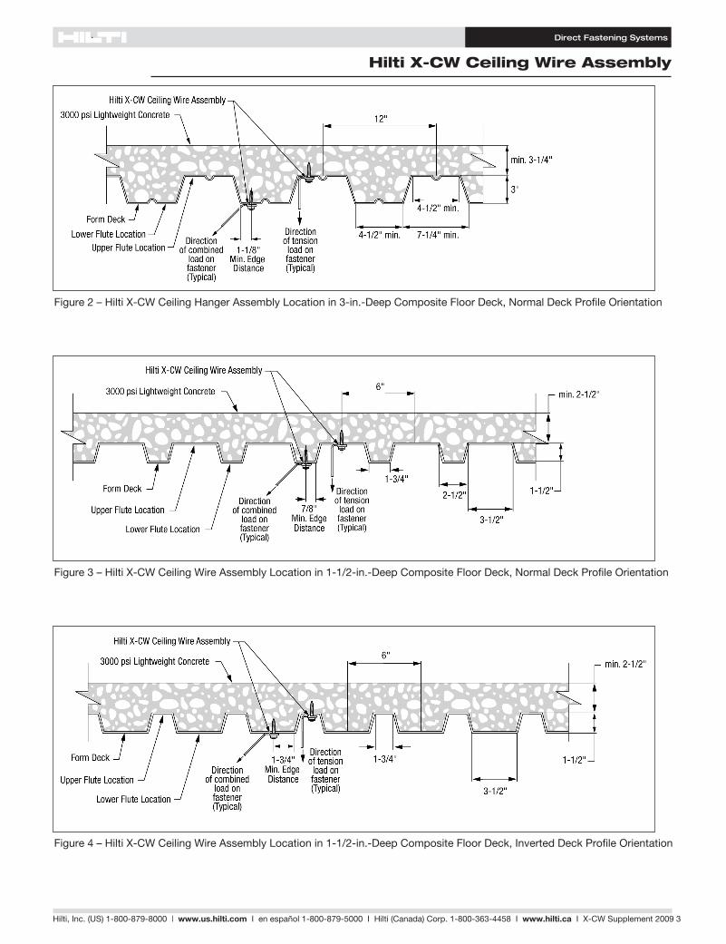
3 Testing completed in composite floor deck having a minimum thickness of 20 gauge (0.0358”) and a minimum yield strength (Fy) of 38 ksi. Figures 2 – 4 show nominal flute dimensions, fastener locations and load orientations for the deck profile. Concrete thickness at the point of penetration must be a minimum of the fastener embedment depth plus 1-1/2”.
4 Mulitple fasteners must be used for suspended ceiling applications.
3000 psi Concrete Compressive Strength Ceiling Wire Type Upper Flute Lower Flute Tension 45-Degree Tension 45 Degree X-CW C27 110 210 100 145
X-CW C32 150 210 100 145
X-CW U27 170 210 150 160
Allowable Loads for Hilti X-CW Ceiling Wire Assemblies Installed in Structural Lightweight Concrete over Composite Floor Deck1,2,3,4
1.2 Material Specifications Powder- Powder- Steel
Steel
Ceiling Ceiling Fastener Actuated Actuated Clamping
Clamping Wire Wire
Designation Fastener Fastener Washer
Washer
Material Plating Material Plating Material Plating
X-CW Carbon
5 μm Zinc1 Carbon 16 μm Zinc2 Carbon
6 μm Zinc3 Steel Steel Steel
1 ASTM B 633, SC 1, Type III
2 ASTM A 653/A 653M, Z120
3 ASTM A 641/A 641M, Class 1
Pre-mounted X-U or X-C fastener (X-U Shown)
Pre-mounted Ceiling Wire Hanger
Pre-mountedsteel clamping washer
Direct Fastening Systems
Hilti X-CW Ceiling Wire Assembly
Hilti, Inc. (US) 1-800-879-8000 | www.us.hilti.com I en español 1-800-879-5000 I Hilti (Canada) Corp. 1-800-363-4458 I www.hilti.ca I X-CW Supplement 2009 2
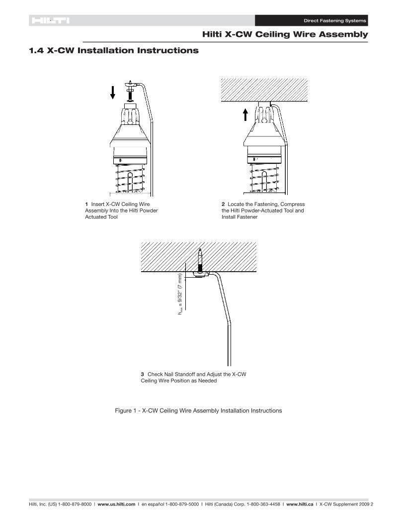
1.4 X-CW Installation Instructions
Figure 1 - X-CW Ceiling Wire Assembly Installation Instructions
3 Check Nail Standoff and Adjust the X-CW Ceiling Wire Position as Needed
1 Insert X-CW Ceiling Wire Assembly Into the Hilti Powder Actuated Tool
2 Locate the Fastening, Compress the Hilti Powder-Actuated Tool and Install Fastener
h nvs
≤ 9
/32"
(7 m
m)
Direct Fastening Systems
Hilti X-CW Ceiling Wire Assembly
Hilti, Inc. (US) 1-800-879-8000 | www.us.hilti.com I en español 1-800-879-5000 I Hilti (Canada) Corp. 1-800-363-4458 I www.hilti.ca I X-CW Supplement 2009 3
Figure 2 – Hilti X-CW Ceiling Hanger Assembly Location in 3-in.-Deep Composite Floor Deck, Normal Deck Profile Orientation
Figure 3 – Hilti X-CW Ceiling Wire Assembly Location in 1-1/2-in.-Deep Composite Floor Deck, Normal Deck Profile Orientation
Figure 4 – Hilti X-CW Ceiling Wire Assembly Location in 1-1/2-in.-Deep Composite Floor Deck, Inverted Deck Profile Orientation
Direct Fastening Systems
Hilti X-CW Ceiling Wire Assembly
Hilti, Inc. (US) 1-800-879-8000 | www.us.hilti.com I en español 1-800-879-5000 I Hilti (Canada) Corp. 1-800-363-4458 I www.hilti.ca I X-CW Supplement 2009 4
WallMoulding
WallMoulding
AcousticalTile
MainRunners
MainRunners
Spline(SpanningCross Runners)
X-CW CeilingWire Assembly
Support Clipfor Main Runners
CarryingChannel
CrossRunners
X-CW CeilingWire Assembly
AccousticalLay-in Panels
Cross Runners(Spanning
Main Runners)
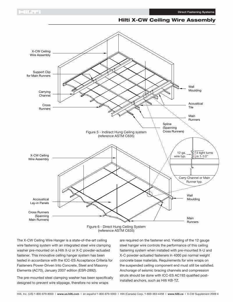
Figure 6 - Direct Hung Ceiling System(reference ASTM C635)
The X-CW Ceiling Wire Hanger is a state-of-the-art ceiling wire fastening system with an integrated steel wire clamping washer pre-mounted on a Hilti X-U or X-C powder-actuated fastener. This innovative ceiling hanger system has been tested in accordance with the ICC-ES Acceptance Criteria for Fasteners Power-Driven Into Concrete, Steel and Masonry Elements (AC70), January 2007 edition (ESR-2892).
The pre-mounted steel clamping washer has been specifically designed to prevent wire slippage, therefore no wire wraps
are required on the fastener end. Yielding of the 12 gauge steel hanger wire controls the performance of this ceiling fastening system when installed with pre-mounted X-U and X-C powder-actuated fasteners in 4000 psi normal weight concrete base materials. Requirements for wire wraps on the suspended ceiling component end must still be satisfied. Anchorage of seismic bracing channels and compression struts should be done with ICC-ES AC193 qualified post-installed anchors, such as Hilti KB-TZ.
WallMoulding
WallMoulding
AcousticalTile
MainRunners
MainRunners
Spline(SpanningCross Runners)
X-CW CeilingWire Assembly
Support Clipfor Main Runners
CarryingChannel
CrossRunners
X-CW CeilingWire Assembly
AccousticalLay-in Panels
Cross Runners(Spanning
Main Runners)
Figure 5 - Indirect Hung Ceiling system(reference ASTM C635)
WallMoulding
MainRunners
X-CW CeilingWire Assembly
AccousticalLay-in Panels
Cross Runners(Spanning
Main Runners)
Carry Channel or Main Runner typ.
3 tight turns in 1-1/2"
12 ga.wire typ.
Direct Fastening Systems
Hilti X-CW Ceiling Wire Assembly
Hilti, Inc. (US) 1-800-879-8000 | www.us.hilti.com I en español 1-800-879-5000 I Hilti (Canada) Corp. 1-800-363-4458 I www.hilti.ca I X-CW Supplement 2009 5
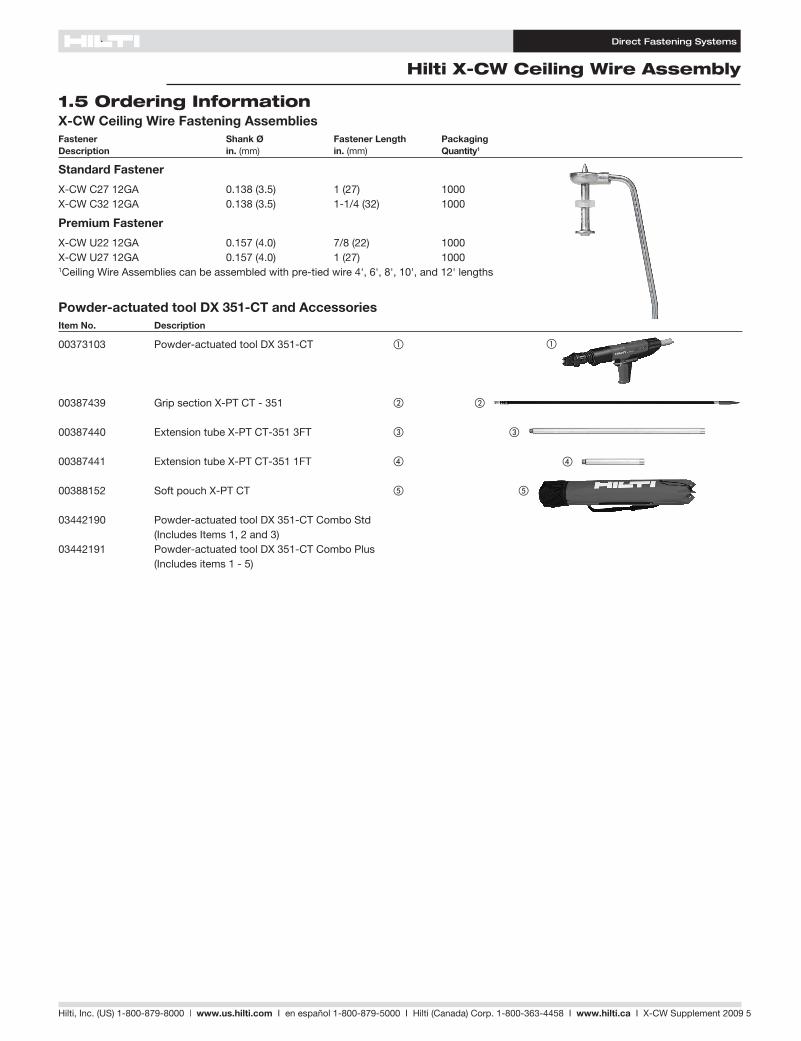
Powder-actuated tool DX 351-CT and Accessories
Item No. Description
00373103 Powder-actuated tool DX 351-CT a
00387439 Grip section X-PT CT - 351 b
00387440 Extension tube X-PT CT-351 3FT c
00387441 Extension tube X-PT CT-351 1FT d
00388152 Soft pouch X-PT CT e
03442190 Powder-actuated tool DX 351-CT Combo Std (Includes Items 1, 2 and 3)03442191 Powder-actuated tool DX 351-CT Combo Plus (Includes items 1 - 5)
X-CW Ceiling Wire Fastening AssembliesFastener Shank Ø Fastener Length PackagingDescription in. (mm) in. (mm) Quantity1
Standard Fastener
X-CW C27 12GA 0.138 (3.5) 1 (27) 1000X-CW C32 12GA 0.138 (3.5) 1-1/4 (32) 1000
Premium Fastener
X-CW U22 12GA 0.157 (4.0) 7/8 (22) 1000X-CW U27 12GA 0.157 (4.0) 1 (27) 10001Ceiling Wire Assemblies can be assembled with pre-tied wire 4', 6', 8', 10', and 12' lengths
1.5 Ordering Information
a
b
c
d
e
Direct Fastening Systems
Notes
Hilti, Inc. (US) 1-800-879-8000 | www.us.hilti.com I en español 1-800-879-5000 I Hilti (Canada) Corp. 1-800-363-4458 I www.hilti.ca I X-CW Supplement 2009 6
*ISO 14001 US Only
P.O. Box 21148, Tulsa, OK 74121 • Hilti, Inc. (US) 1-800-879-8000 www.us.hilti.com • Servicio al Cliente en español 1-800-879-5000 • Hilti (Canada) Corporation 1-800-363-4458 www.hilti.ca • Hilti is an equal opportunity employer • Hilti is a registered trademark of Hilti, Corp. ©Copyright 2007 by Hilti, Inc. • 10/09 • BB
The data contained in this literature was current as of the date of publication. Updates and changes may be made based on later testing. If verification is needed that the data is still current, please contact the Hilti Technical Support Specialists at 1-800-879-8000. All published load values contained in this literature represent the results of testing by Hilti or test organizations. Local base materials were used. Because of variations in materials, on-site testing is necessary to determine performance at any specific site. Printed in the United States
Hilti. Outperform. Outlast.