![Floor Plans Capacity Charts - Cloudinary · To DJT Ballroom Juniper 2,322 sq. ft. [] Jones Courtyard Ginger 3,276 sq. ft. 567 sq. ft. Lantana 760 sq. ft. 648 sq. ft. Rose 760 sq.](https://static.fdocuments.us/doc/165x107/5ec70014e020fb7bed7efd7d/floor-plans-capacity-charts-cloudinary-to-djt-ballroom-juniper-2322-sq-ft-.jpg)
DATASHEET SQ RI SERIES - Home | SignalQuest - Precision ... Rugged Package SQ-RI.pdf · Lebanon, NH...
15
DATASHEET SQ-RI SERIES RUGGED PACKAGED INCLINOMETER, CAN2.0B/J1939 Updated: 2014-01-16 © SignalQuest, LLC 2014 10 Water St. Lebanon, NH 03766 USA Tel: 603.448.6266 Fax 603.218.6426 www.signalquest.com [email protected] 1 THEORY OF OPERATION The inclinometer uses two factory calibrated accelerometers to measure and compute angles made between its axes and the gravity vector. The trigonometric conversions between acceleration and angle are made by an onboard processor. Digital filtering reduces the impact of spurious acceleration and vibration on the reported angle. LOW RANGE “RIL” MODEL In Dual-Axis Mode the RIW sensor measures inclination between the earth and its X and Y axes with a range of ±70 o . In Single-Axis Mode the RIW sensor measures full-scale rotation about the Z axis with a range of 360 o . The sensor must be oriented such that the Z axis is parallel to the ground. WIDE RANGE “RIW” MODEL The sensor measures between earth and its X and Y axes with a range of 360 o in one axis and 180 o in the other. CAN BUSSING OPTIONS The SQ-RI supports CAN2.0 bus rates up to 1.0 Mbps and can be connected to the bus either in-line or on a tap. The CAN bus is internally terminated in models with a single connector FUNCTION LOW RANGE “RIL” MODEL ± 70 º dual axis angle measurement 360 º single axis angle measurement WIDE RANGE "RIW" MODEL Wide range 360 º x 180 º dual axis angle measurement APPLICATIONS Platform and vehicle leveling Satellite dish and antenna alignment Machine control and monitoring Angle measurement and recording Computer input, head tracking, and mouse pointing DESCRIPTION The SQ-RI contains a high accuracy inclinometer, robust power conditioning and a CAN2.0B/J1939 interface controller all potted in an industrial enclosure. A Deutch DTF series connector is standard; M12, flying lead and other connector options are available. FEATURES ± 0.1 º and ± 0.01 º resolution options IP65, IP67 and IP68 options Low temperature drift Factory calibrated angle output High reliability solid-state MEMS Digital filtering for stable measurement ALTERNATE HOUSINGS A variety of enclosures are available. Please consult the factory for different enclosures, connectors and cabling options.
Transcript of DATASHEET SQ RI SERIES - Home | SignalQuest - Precision ... Rugged Package SQ-RI.pdf · Lebanon, NH...

DATASHEET
SQ-RI SERIES
RUGGED PACKAGED INCLINOMETER, CAN2.0B/J1939
Updated: 2014-01-16 © SignalQuest, LLC
2014
10 Water St.
Lebanon, NH 03766 USA
Tel: 603.448.6266
Fax 603.218.6426
www.signalquest.com
1
THEORY OF OPERATION The inclinometer uses two factory calibrated accelerometers
to measure and compute angles made between its axes and the
gravity vector. The trigonometric conversions between
acceleration and angle are made by an onboard processor.
Digital filtering reduces the impact of spurious acceleration
and vibration on the reported angle.
LOW RANGE “RIL” MODEL In Dual-Axis Mode the RIW sensor measures inclination
between the earth and its X and Y axes with a range of
±70 o.
In Single-Axis Mode the RIW sensor measures full-scale
rotation about the Z axis with a range of 360 o. The sensor
must be oriented such that the Z axis is parallel to the ground.
WIDE RANGE “RIW” MODEL The sensor measures between earth and its X and Y axes with
a range of 360 o in one axis and 180 o in the other.
CAN BUSSING OPTIONS The SQ-RI supports CAN2.0 bus rates up to 1.0 Mbps and
can be connected to the bus either in-line or on a tap. The
CAN bus is internally terminated in models with a single
connector
FUNCTION LOW RANGE “RIL” MODEL
± 70 º dual axis angle measurement
360 º single axis angle measurement
WIDE RANGE "RIW" MODEL
Wide range 360 º x 180 º dual axis angle
measurement
APPLICATIONS Platform and vehicle leveling
Satellite dish and antenna alignment Machine control and monitoring
Angle measurement and recording
Computer input, head tracking, and mouse
pointing
DESCRIPTION The SQ-RI contains a high accuracy inclinometer,
robust power conditioning and a CAN2.0B/J1939
interface controller all potted in an industrial enclosure.
A Deutch DTF series connector is standard; M12,
flying lead and other connector options are available.
FEATURES ± 0.1 º and ± 0.01 º resolution options
IP65, IP67 and IP68 options
Low temperature drift
Factory calibrated angle output High reliability solid-state MEMS
Digital filtering for stable measurement
ALTERNATE HOUSINGS A variety of enclosures are available. Please consult
the factory for different enclosures, connectors and
cabling options.
DATASHEET
SQ-RI SERIES
RUGGED PACKAGED INCLINOMETER, CAN2.0B/J1939
Updated: 2014-01-16 © SignalQuest, LLC
2014
10 Water St.
Lebanon, NH 03766 USA
Tel: 603.448.6266
Fax 603.218.6426
www.signalquest.com
2
TABLE OF CONTENTS
Performance Characteristics ................................................................................................................................................. 3
Absolute Maximum Ratings ................................................................................................................................................. 3
Electrical Characteristics ...................................................................................................................................................... 3
Comparison Data for Models and Options ............................................................................................................................ 4
Pin Configuration ................................................................................................................................................................. 5
Addressing ........................................................................................................................................................................... 6
CAN Packet Data Format: Dual-Axis (RIL), Tilt/Gimballed Mode (RIW) ............................................................................. 6
CAN Packet Data Format: Single-Axis ................................................................................................................................. 7
Orientation ........................................................................................................................................................................... 8
SQ-RIL Model ..................................................................................................................................................................... 8
SQ-RIW Model .................................................................................................................................................................... 9
Packaging .......................................................................................................................................................................... 10
Ordering Options ............................................................................................................................................................... 12
Ordering Options ............................................................................................................................................................... 13
Limitations and Warnings ................................................................................................................................................... 14
Testing ............................................................................................................................................................................... 14
System Integration Testing ................................................................................................................................................. 14
Notice ................................................................................................................................................................................ 14
Further Information ............................................................................................................................................................ 15

DATASHEET
SQ-RI SERIES
RUGGED PACKAGED INCLINOMETER, CAN2.0B/J1939
Updated: 2014-01-16 © SignalQuest, LLC
2014
10 Water St.
Lebanon, NH 03766 USA
Tel: 603.448.6266
Fax 603.218.6426
www.signalquest.com
3
PERFORMANCE CHARACTERISTICS
PARAMETER SPECIFICATION UNITS
Axes 2
Case alignment 0.1 o
Accuracy 0.1 o
Zero point temp drift 0.005 o/ oC
Settling time 0.1 / 0.5 s
Update rate 40 Hz
Nonlinearity < 0.5 % FSR
Operating Temperature -40 to 85 oC
Transverse sensitivity < 1 % at 30ºC
Operating Vibration 1.7 gn1
Shock Survivability 500 gn
I/O ESD Protection - HBM 16 kV
ABSOLUTE MAXIMUM RATINGS
PARAMETER MIN MAX UNITS
Supply Voltage (-5R model) -40 24 Vdc
Supply Voltage (-36R model) -40 40 Vdc
Voltage on any I/O pin -0.7 5.8 Vdc
CANH/CANL -4 16 Vdc
-11 11 mA
CANH-CANL Differential -6 6 Vdc
ELECTRICAL CHARACTERISTICS
PARAMETER MIN TYP MAX UNITS
Supply Voltage (-5R) 4.5 12 Vdc
Supply Voltage (-36R) 7 36 Vdc
Supply Current 50 mA
CAN Bus Rate 250 1000 kbps
1 Where 1 gn is approximately 9.80m/s2
DATASHEET
SQ-RI SERIES
RUGGED PACKAGED INCLINOMETER, CAN2.0B/J1939
Updated: 2014-01-16 © SignalQuest, LLC
2014
10 Water St.
Lebanon, NH 03766 USA
Tel: 603.448.6266
Fax 603.218.6426
www.signalquest.com
4
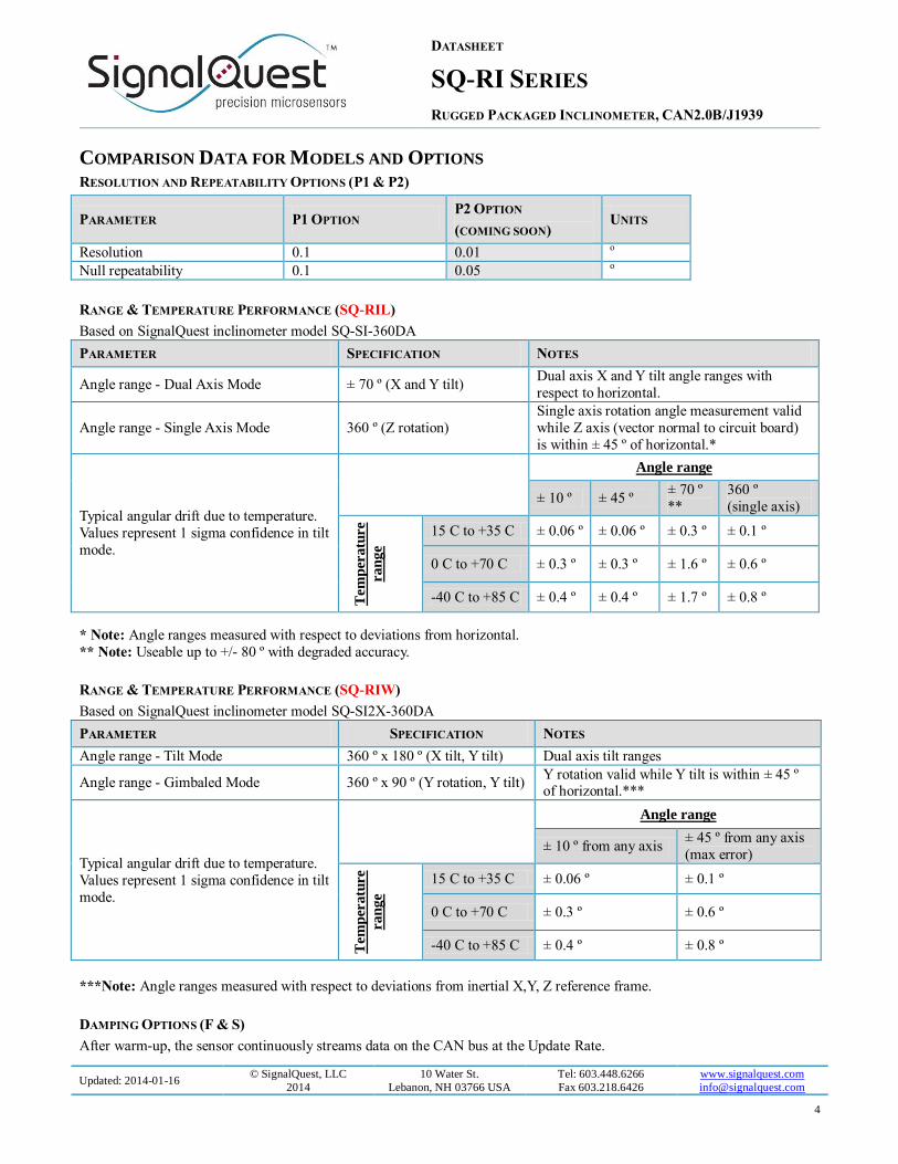
COMPARISON DATA FOR MODELS AND OPTIONS RESOLUTION AND REPEATABILITY OPTIONS (P1 & P2)
PARAMETER P1 OPTION P2 OPTION
(COMING SOON) UNITS
Resolution 0.1 0.01 o
Null repeatability 0.1 0.05 o
RANGE & TEMPERATURE PERFORMANCE (SQ-RIL)
Based on SignalQuest inclinometer model SQ-SI-360DA
PARAMETER SPECIFICATION NOTES
Angle range - Dual Axis Mode ± 70 º (X and Y tilt) Dual axis X and Y tilt angle ranges with
respect to horizontal.
Angle range - Single Axis Mode 360 º (Z rotation)
Single axis rotation angle measurement valid
while Z axis (vector normal to circuit board)
is within ± 45 º of horizontal.*
Typical angular drift due to temperature.
Values represent 1 sigma confidence in tilt
mode.
Angle range
± 10 º ± 45 º ± 70 º
**
360 º
(single axis)
Tem
per
atu
re
ra
ng
e
15 C to +35 C ± 0.06 º ± 0.06 º ± 0.3 º ± 0.1 º
0 C to +70 C ± 0.3 º ± 0.3 º ± 1.6 º ± 0.6 º
-40 C to +85 C ± 0.4 º ± 0.4 º ± 1.7 º ± 0.8 º
* Note: Angle ranges measured with respect to deviations from horizontal.
** Note: Useable up to +/- 80 º with degraded accuracy.
RANGE & TEMPERATURE PERFORMANCE (SQ-RIW)
Based on SignalQuest inclinometer model SQ-SI2X-360DA
PARAMETER SPECIFICATION NOTES
Angle range - Tilt Mode 360 º x 180 º (X tilt, Y tilt) Dual axis tilt ranges
Angle range - Gimbaled Mode 360 º x 90 º (Y rotation, Y tilt) Y rotation valid while Y tilt is within ± 45 º of horizontal.***
Typical angular drift due to temperature.
Values represent 1 sigma confidence in tilt
mode.
Angle range
± 10 º from any axis ± 45 º from any axis
(max error)
Tem
per
atu
re
ran
ge
15 C to +35 C ± 0.06 º ± 0.1 º
0 C to +70 C ± 0.3 º ± 0.6 º
-40 C to +85 C ± 0.4 º ± 0.8 º
***Note: Angle ranges measured with respect to deviations from inertial X,Y, Z reference frame.
DAMPING OPTIONS (F & S)
After warm-up, the sensor continuously streams data on the CAN bus at the Update Rate.

DATASHEET
SQ-RI SERIES
RUGGED PACKAGED INCLINOMETER, CAN2.0B/J1939
Updated: 2014-01-16 © SignalQuest, LLC
2014
10 Water St.
Lebanon, NH 03766 USA
Tel: 603.448.6266
Fax 603.218.6426
www.signalquest.com
5
Parameter F Option S Option Notes
Warm up time from power on 0.2 s 1.0 s Angle jitter and vibration are digitally filtered
Measurement settling time 0.1 s 0.5 s
Update Rate 40 Hz Update rate is factory configurable – contact SignalQuest for
other options
PIN CONFIGURATION
SINGLE CONNECTOR MODELS & PRIMARY CONNECTOR ON DUAL CONNECTOR MODELS
Pin Signal Name Usage
1 SWCLK Factory Programming Interface
2 ADDR_0 Address I/0 Line
3 V+ Voltage Supply
4 GND Ground
5 C2CK Factory Programming Interface
6 C2D Factory Programming Interface
7 SWDIO Factory Programming Interface
8 CAN_L CAN Bus L Signal
9 CAN_H CAN Bus H Signal
10 CAN_SHLD CAN Shield
11 RST Factory Programming Interface
12 ADDR_1 Address I/O Line
*Note: Grey boxes indicate that a signal is available only on a custom application basis.
SECONDARY CONNECTOR ON DUAL CONNECTOR MODELS
Pin Signal Name Usage
1 IO_A Reserved I/O
2 IO_B Reserved I/O
3 GND Ground
4 V+ Voltage Supply
5 IO_C Reserved I/O
6 C2CK Factory Programming Interface
7 IO_D Reserved I/O
8 IO_E Reserved I/O
9 CAN_SHLD CAN Shield
10 CAN_H CAN Bus H Signal
11 CAN_L CAN Bus L Signal
12 C2D Factory Programming Interface
DATASHEET
SQ-RI SERIES
RUGGED PACKAGED INCLINOMETER, CAN2.0B/J1939
Updated: 2014-01-16 © SignalQuest, LLC
2014
10 Water St.
Lebanon, NH 03766 USA
Tel: 603.448.6266
Fax 603.218.6426
www.signalquest.com
6
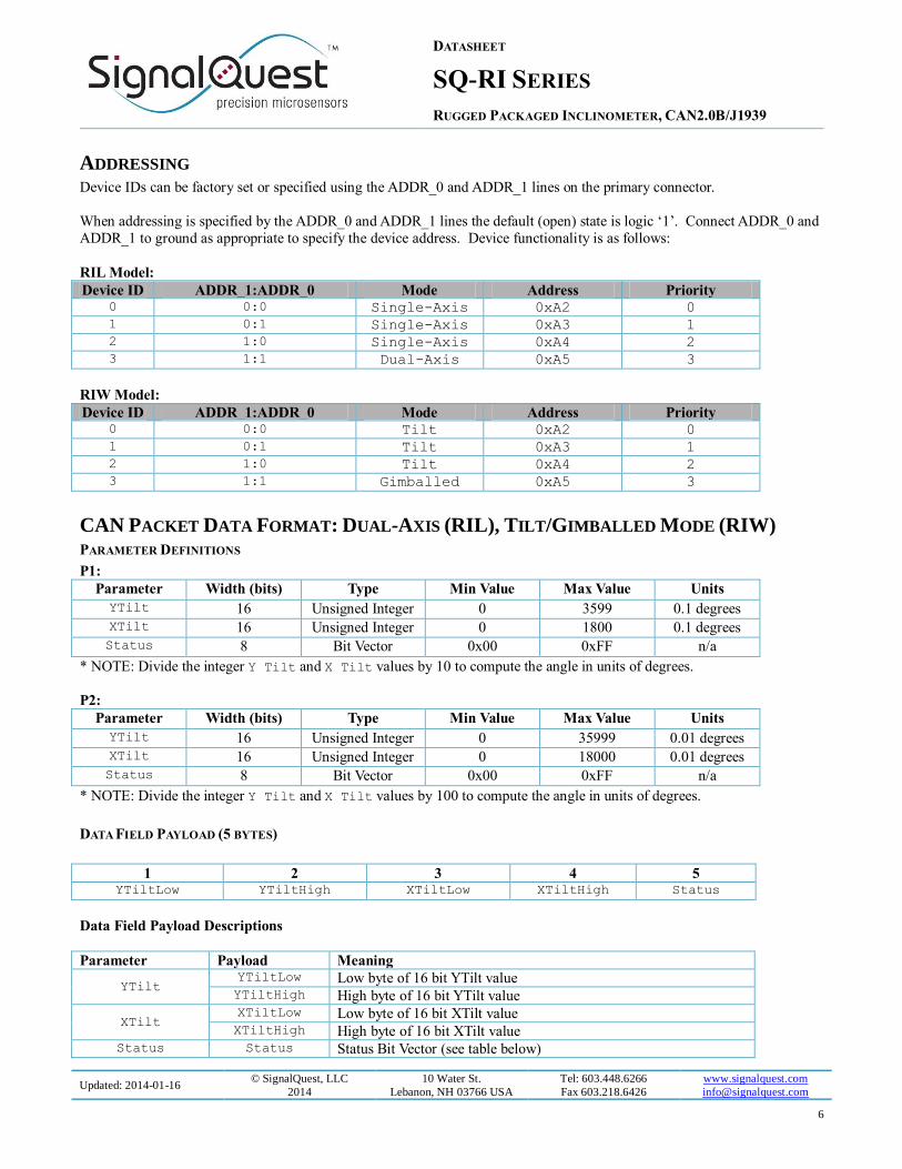
ADDRESSING Device IDs can be factory set or specified using the ADDR_0 and ADDR_1 lines on the primary connector.
When addressing is specified by the ADDR_0 and ADDR_1 lines the default (open) state is logic ‘1’. Connect ADDR_0 and
ADDR_1 to ground as appropriate to specify the device address. Device functionality is as follows:
RIL Model:
Device ID ADDR_1:ADDR_0 Mode Address Priority 0 0:0 Single-Axis 0xA2 0
1 0:1 Single-Axis 0xA3 1
2 1:0 Single-Axis 0xA4 2
3 1:1 Dual-Axis 0xA5 3
RIW Model:
Device ID ADDR_1:ADDR_0 Mode Address Priority 0 0:0 Tilt 0xA2 0
1 0:1 Tilt 0xA3 1
2 1:0 Tilt 0xA4 2
3 1:1 Gimballed 0xA5 3
CAN PACKET DATA FORMAT: DUAL-AXIS (RIL), TILT/GIMBALLED MODE (RIW) PARAMETER DEFINITIONS
P1:
Parameter Width (bits) Type Min Value Max Value Units
YTilt 16 Unsigned Integer 0 3599 0.1 degrees
XTilt 16 Unsigned Integer 0 1800 0.1 degrees
Status 8 Bit Vector 0x00 0xFF n/a
* NOTE: Divide the integer Y Tilt and X Tilt values by 10 to compute the angle in units of degrees.
P2:
Parameter Width (bits) Type Min Value Max Value Units
YTilt 16 Unsigned Integer 0 35999 0.01 degrees
XTilt 16 Unsigned Integer 0 18000 0.01 degrees
Status 8 Bit Vector 0x00 0xFF n/a
* NOTE: Divide the integer Y Tilt and X Tilt values by 100 to compute the angle in units of degrees.
DATA FIELD PAYLOAD (5 BYTES)
1 2 3 4 5 YTiltLow YTiltHigh XTiltLow XTiltHigh Status
Data Field Payload Descriptions
Parameter Payload Meaning
YTilt YTiltLow Low byte of 16 bit YTilt value YTiltHigh High byte of 16 bit YTilt value
XTilt XTiltLow Low byte of 16 bit XTilt value XTiltHigh High byte of 16 bit XTilt value
Status Status Status Bit Vector (see table below)

DATASHEET
SQ-RI SERIES
RUGGED PACKAGED INCLINOMETER, CAN2.0B/J1939
Updated: 2014-01-16 © SignalQuest, LLC
2014
10 Water St.
Lebanon, NH 03766 USA
Tel: 603.448.6266
Fax 603.218.6426
www.signalquest.com
7
The Status bit vector flags the following conditions – note that Status = 0 indicates normal operation:
Bit Vector Position Flag Meaning
0 (LSB) 0x01 Sensor Warming Up
4 0x10 Sensor Synchronization Lost
6 0x40 Device ID changed after power-on – possible wiring fault
7 0x80 Firmware fault – device restarted by internal watchdog monitor
CAN PACKET DATA FORMAT: SINGLE-AXIS PARAMETER DEFINITIONS
P1:
Parameter Width (bits) Type Min Value Max Value* Units
ZRotation 16 Unsigned Integer 0 3599 0.1 degrees
ZTilt 16 Unsigned Integer 0 1800 0.1 degrees
Status 8 Bit Vector 0x00 0xFF n/a
* NOTE: Divide the integer Y Tilt and X Tilt values by 10 to compute the angle in units of degrees.
P2:
Parameter Width (bits) Type Min Value Max Value* Units
ZRotation 16 Unsigned Integer 0 35999 0.01 degrees
ZTilt 16 Unsigned Integer 0 18000 0.01 degrees
Status 8 Bit Vector 0x00 0xFF n/a
* NOTE: Divide the integer Y Tilt and X Tilt values by 100 to compute the angle in units of degrees.
DATA FIELD PAYLOAD (5 BYTES)
1 2 3 4 5 ZRotationLow ZRotationHigh ZTiltLow ZTiltHigh Status
Data Field Payload Descriptions
Parameter Payload Meaning
ZRotation
ZRotationLow Low byte of 16 bit Rotation value ZRotation
High High byte of 16 bit Rotation value
ZTilt ZTiltLow Low byte of 16 bit Tilt value ZTiltHigh High byte of 16 bit Tilt value
Status Status Status Bit Vector (see table below)
The Status bit vector flags the following conditions – note that Status = 0 indicates normal operation:
Bit Vector Position Flag Meaning
0 (LSB) 0x01 Sensor Warming Up
4 0x10 Sensor Synchronization Lost
6 0x40 Device ID changed after power-on – possible wiring fault
7 0x80 Firmware fault – device restarted by internal watchdog monitor

DATASHEET
SQ-RI SERIES
RUGGED PACKAGED INCLINOMETER, CAN2.0B/J1939
Updated: 2014-01-16 © SignalQuest, LLC
2014
10 Water St.
Lebanon, NH 03766 USA
Tel: 603.448.6266
Fax 603.218.6426
www.signalquest.com
8
ORIENTATION TERMINOLOGY
Gravity means a vector pointing from the device toward the center of the earth.
X means a vector parallel to the “X” arrow printed on housing label
Y means a vector parallel to the “Y” arrow printed on the housing label
Z means a vector passing through “Z” arrow printed on the housing label
Horizontal means the arrow is pointing at a right angle to gravity.
Straight Down means the arrow is parallel to gravity.
Straight Up means that the arrow is anti-parallel to gravity (i.e. pointing toward the sky).
Plumb Line is a line with a weight on the end hanging straight down.
SQ-RIL MODEL DUAL -AXIS MODE
In Dual-Axis Mode the X Tilt and Y Tilt angles are measured between gravity and the arrows printed on the housing label. If
you passed a Plumb Line through the sensor’s X, Y, Z origin, the X and Y Tilt angles could be measured by placing a
protractor’s straight edge on the plum line and then reading the angles made with each arrow.
Y Tilt = Pitch (first angle)
X Tilt = Roll (second angle)
Holding Y Horizontal
When X is Horizontal, X Tilt = 90 º.
When X is Straight Up, X Tilt = ~180 º.
When X is Straight Down, X Tilt = ~0 º.
Holding X Horizontal
When Y is Horizontal, Y Tilt = 90 º.
When Y is Straight Up, Y Tilt = ~180 º.
When Y is Straight Down, Y Tilt = ~0 º.
SINGLE -AXIS MODE
In Single-Axis Mode, the Z Rotation angle is defined as a rotation about the Z axis of the sensor. For the Z Axis Rotation angle to remain in range, the Z Axis must be near horizontal. The Z axis should be kept to less than ± 45 º of deviation from
horizontal. Pitch angle values are factory calibrated to within +/- 0.1o alignment with the sensor enclosure
.
When X is Horizontal, Y is Straight Up, Z Rotation = 0 / 360 º.
When Y is Horizontal, X is Straight Down, Z Rotation = 90 º.
When X is Horizontal, Y is Straight Down, Z Rotation = 180 º.
When Y is Horizontal, X is Straight Up, Z Rotation = 270 º.
IMPORTANT NOTES
Regardless of the mode, the inclinometer measures angles with respect to gravity. It cannot measure rotation about the gravity vector. All rotations about gravity are invisible to the sensor and are considered equivalent.

DATASHEET
SQ-RI SERIES
RUGGED PACKAGED INCLINOMETER, CAN2.0B/J1939
Updated: 2014-01-16 © SignalQuest, LLC
2014
10 Water St.
Lebanon, NH 03766 USA
Tel: 603.448.6266
Fax 603.218.6426
www.signalquest.com
9
SQ-RIW MODEL TILT MODE
In Tilt Mode the X Tilt and Y Tilt angles are measured between gravity and the white silkscreen arrows printed on the main
circuit board. If you passed a Plumb Line through the inclinometer’s X, Y, Z origin, the X and Y Tilt angles could be
measured by placing a protractor’s straight edge on the plum line and then reading the angles made with each arrow.
Y Tilt = Pitch (first angle)
X Tilt = Roll (second angle)
Holding Y Horizontal
When X is Horizontal and Z is Straight Up, X Tilt = 90 º.
When X is Horizontal and Z is Straight Down, X Tilt = 270 º.
When X is Straight Up, X Tilt = 180 º. When X is Straight Down, X Tilt = 0 / 360 º.
Holding X Horizontal
When Y is Horizontal, Y Tilt = 90 º.
When Y is Straight Up, Y Tilt = 0 º.
When Y is Straight Down, Y Tilt = 180 º.
GIMBALED MODE
In both Tilt Mode and Gimbaled Mode, the Y Tilt measurement is identical. However, in Gimbaled Mode, the Y Rotation
angle is defined as a rotation about the Y axis of the device. You will find that this is similar to X Tilt (in Tilt Mode) when
near horizontal, but further from horizontal, the difference between these two measurement methods is quite pronounced. .
For users familiar with Euler Angles, this measurement mode is equivalent to performing the Euler X-Y transformation on
the Tilt Mode coordinates, and then adjusting the quadrants to be continuous. In Gimbaled Mode unlike Tilt Mode, there will
be no numerical discontinuities near 0 and 180 degrees for X Tilt, when Y is not Horizontal.
IMPORTANT NOTES
Tilt Mode angles are not generally equivalent to Gimbaled Mode angles. Tilting X up or down in the Tilt Mode
coordinate system is not equivalent to making a rotation about the Y axis unless Y is fixed horizontally. The same is
true for the X axis. Consult SignalQuest technical support and reference material on orientation reference frames.
Users wanting to measure rotations about the inclinometer’s Y axes rather than tilt angle with respect to gravity,
should use the Gimbaled Mode coordinate system. To convert a dataset from Tilt Mode coordinates (the sensor’s native output) to Gimbaled Mode coordinates, contact SignalQuest for application notes and sample software.
Regardless of the coordinate frame used the inclinometer measures angles with respect to gravity. It cannot measure
rotation about the gravity vector. All rotations about gravity are invisible to the sensor and are considered
equivalent.
DATASHEET
SQ-RI SERIES
RUGGED PACKAGED INCLINOMETER, CAN2.0B/J1939
Updated: 2014-01-16 © SignalQuest, LLC
2014
10 Water St.
Lebanon, NH 03766 USA
Tel: 603.448.6266
Fax 603.218.6426
www.signalquest.com
10
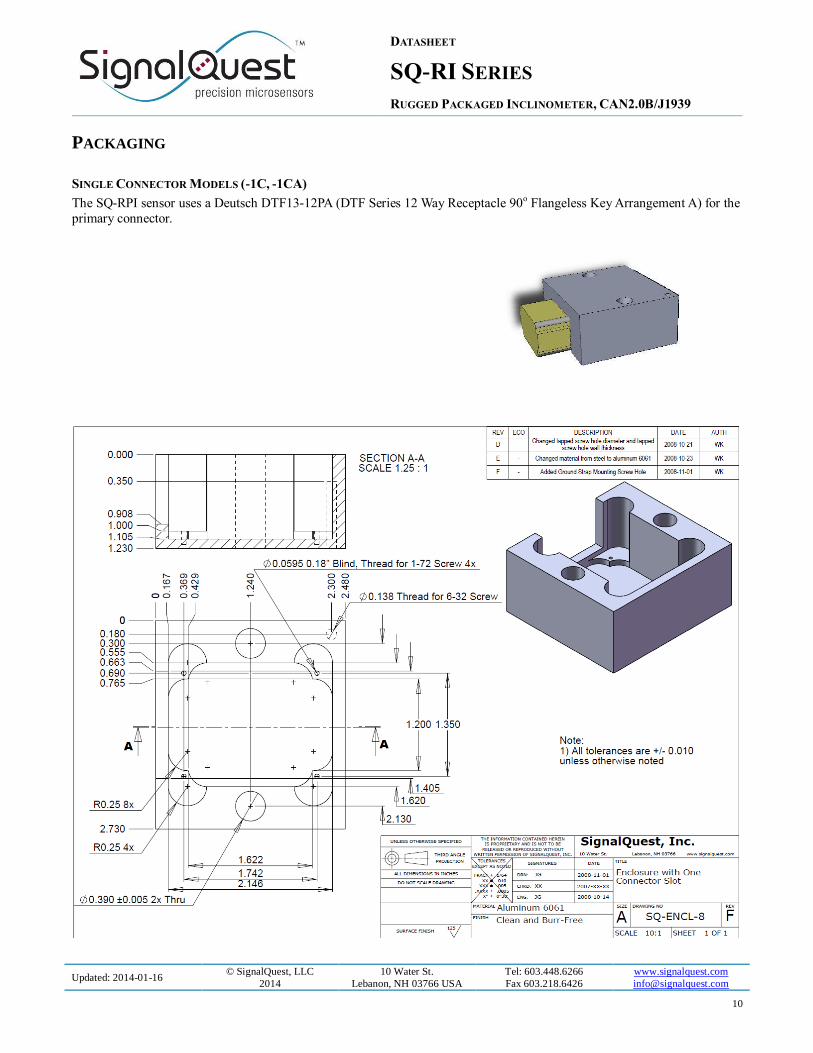
PACKAGING
SINGLE CONNECTOR MODELS (-1C, -1CA)
The SQ-RPI sensor uses a Deutsch DTF13-12PA (DTF Series 12 Way Receptacle 90o Flangeless Key Arrangement A) for the
primary connector.
DATASHEET
SQ-RI SERIES
RUGGED PACKAGED INCLINOMETER, CAN2.0B/J1939
Updated: 2014-01-16 © SignalQuest, LLC
2014
10 Water St.
Lebanon, NH 03766 USA
Tel: 603.448.6266
Fax 603.218.6426
www.signalquest.com
11
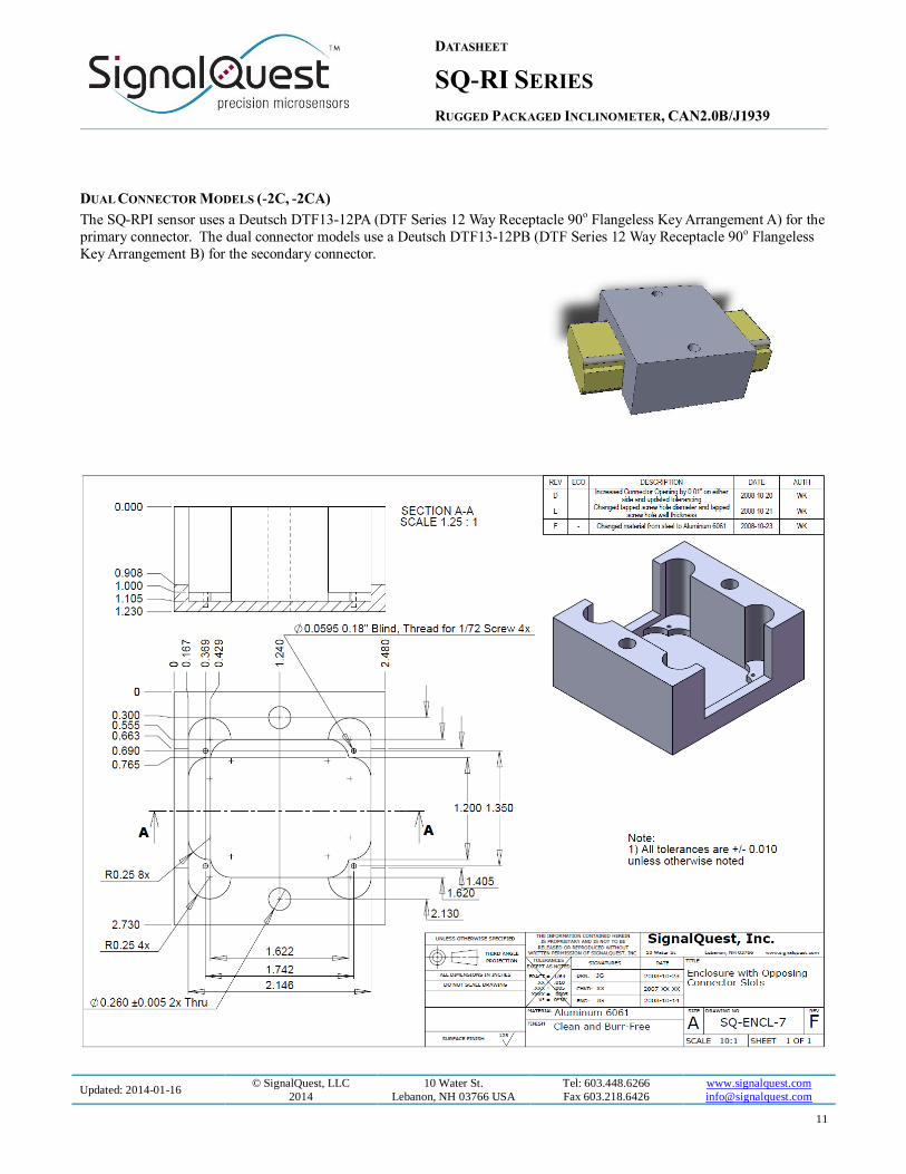
DUAL CONNECTOR MODELS (-2C, -2CA)
The SQ-RPI sensor uses a Deutsch DTF13-12PA (DTF Series 12 Way Receptacle 90o Flangeless Key Arrangement A) for the
primary connector. The dual connector models use a Deutsch DTF13-12PB (DTF Series 12 Way Receptacle 90o Flangeless
Key Arrangement B) for the secondary connector.

DATASHEET
SQ-RI SERIES
RUGGED PACKAGED INCLINOMETER, CAN2.0B/J1939
Updated: 2014-01-16 © SignalQuest, LLC
2014
10 Water St.
Lebanon, NH 03766 USA
Tel: 603.448.6266
Fax 603.218.6426
www.signalquest.com
12
SMALL PACKAGE FLYING LEAD (-3C)
1. IP65 protection rating
2. Flying lead, small form factor
3. 8 conductor, flying lead
4. Only tap bus topology support at this time.
Pin Signal Name Color Usage
1 Factory 1
Factory Programming Interface 2 Factory 2
3 Factory 3
4 V+ Voltage Supply
5 GND Ground
6 CAN_L CAN Bus L Signal
7 CAN_H CAN Bus H Signal
8 CAN_SHLD CAN Shield

DATASHEET
SQ-RI SERIES
RUGGED PACKAGED INCLINOMETER, CAN2.0B/J1939
Updated: 2014-01-16 © SignalQuest, LLC
2014
10 Water St.
Lebanon, NH 03766 USA
Tel: 603.448.6266
Fax 603.218.6426
www.signalquest.com
13
ORDERING OPTIONS
OPTIONS CODE OPTION NOTES
Model
SQ-RIL Dual-Axis: ± 70 o dual
Single-Axis: 360 o Low range
SQ-RIW Dual-Axis: 360 o x 180 o Wide range
Pow
er
regula
tor
opti
on
-12R 5 – 15 V supply
-36R
7 – 36 V supply
Standard version (stock)
CONNECTOR TYPE PACKAGE TYPE PROTECTION
RATING
BUS TOPOLOGY NOTES
Pac
kag
e o
pti
on
-1C 1 Deutsch, 12 pin SQ-ENCL-8 IP67 Tap bus (internal
CAN terminator)
-1CA 1 Deutsch, 12 pin, black
anodized
SQ-ENCL-8 IP67 Tap bus (internal
CAN terminator)
-2C 2 Deutsch, 12 pin SQ-ENCL-7 IP67 In-line bus
-2CA 2Deutsch, 12 pin, black
anodized
SQ-ENCL-7 IP67 In-line bus
-3C Flying lead SQ-ENCL-3 IP65 Tap bus (internal
CAN terminator)
-4C 1 circular connector SQ-ENCL-9 IP68 Tap bus (internal
CAN terminator)
-5C 2 circular connectors SQ-ENCL-10 IP68 In-line bus
-7C 1 connector, low cost SQ-ENCL-11 IP67 Tap bus (internal
CAN terminator)
-8C 2 connector, low cost SQ-ENCL-11 IP67 In-line bus
Per
form
ance
op
tion
-P1 Standard performance Standard accuracy and resolution
-P2 High performance Higher accuracy and resolution
Dam
pin
g o
pti
on
-S 500 mS settling time Better noise rejection, slower response time –
This model uses a 0.5 second moving average filter to provide digital
damping. This reduces the impact that spurious accelerations and
vibrations have on the angle reading. This model will reject noise
better than the “F” model, but with the tradeoff of a slower response
time.
-F 100 mS settling time Faster response time, poorer noise rejection – This model uses a 0.1 second moving average filter to provide digital
damping. This model will respond more quickly to changes in angle
than the “S” model, but with the trade off of poorer noise rejection.
Ad
dre
ssin
g
op
tion
ID0 ID0 (Address 0xA2)
ID1 ID1 (Address 0xA3)
ID2 ID2 (Address 0xA4)
ID3 ID3 (Address 0xA5)
IDX Hardware Addressable
IDS Software Addressable Coming soon

DATASHEET
SQ-RI SERIES
RUGGED PACKAGED INCLINOMETER, CAN2.0B/J1939
Updated: 2014-01-16 © SignalQuest, LLC
2014
10 Water St.
Lebanon, NH 03766 USA
Tel: 603.448.6266
Fax 603.218.6426
www.signalquest.com
14
Oth
er
opti
on -Custom Customer-specific
requirements
Please contact SignalQuest if you require an option not listed in this
table. For example, various baud rates, setting times, update rates and
voltage regulator options may be available on request.
All SQ-RI devices are based on the SQ-SI or SI2X base inclinometer. For more information about inclinometer
specifications not listed here, please refer to http://www.signalquest.com/sq-si.htm
Example part numbers: SQ-RIL-12R-1C-P1-S-IDX
LIMITATIONS AND WARNINGS
LIFE SAFETY
This product is not designed for use in life support and/or safety equipment where malfunction of the product can reasonably
be expected to result in personal injury or death. Buyer uses this product in such applications at Buyer’s own risk and agrees
to defend, indemnify, and hold harmless SignalQuest, LLC from any and all damages, claims, suits, or expenses resulting
from such misuse.
DYNAMIC ENVIRONMENTS
The device is designed to be used to measure angles in a quasi-static environment where external vibrations and accelerations
are kept to a minimum. Digital and analog signal processing methods are employed to reduce the effects of transient
acceleration and small vibrations on the angle reading; however, under dynamic conditions where external accelerations or
vibrations are present, the sensor’s performance may be degraded.
VARIATIONS IN EARTH’S GRAVITY
This device is designed to be used near the earth’s surface only. Substantial changes in gravity will degrade the performance
of the sensor. This device is not intended or qualified to be used in aviation.
TESTING The performance of each system is verified through build-time testing. Each system is tested before and after factory
calibration to ensure reliable performance.
SYSTEM INTEGRATION TESTING Thorough testing should be carried out prior to product release to ensure system integration has not introduced unforeseen
problems. The system integrator assumes the ultimate responsibility for the safety of the target application.
NOTICE Information furnished by SignalQuest, Inc is believed to be accurate and reliable. However, this document may contain
ERRORS and OMMISIONS. Accordingly, the design engineer should use this document as a reference rather than a strict
design guideline and should perform thorough testing of any product that incorporates this or any other SignalQuest product.
No responsibility is assumed by SignalQuest, LLC for this use of this information, or for any infringements of patents or other rights of third parties that may result from its use. Specifications are subject to change without notice. No license is
granted by implication or otherwise under any patent or patent rights of SignalQuest, LLC Trademarks and registered
trademarks are the property of their respective companies.
DATASHEET
SQ-RI SERIES
RUGGED PACKAGED INCLINOMETER, CAN2.0B/J1939
Updated: 2014-01-16 © SignalQuest, LLC
2014
10 Water St.
Lebanon, NH 03766 USA
Tel: 603.448.6266
Fax 603.218.6426
www.signalquest.com
15
FURTHER INFORMATION For pricing, delivery, and ordering information, please contact SignalQuest at (603) 448-6266
For updates on this and other documents, visit our website at www.signalquest.com