Datasheet: QCI-DS030 QuickSilver Controls, Inc. - MACCON · Datasheet: QCI-DS030 QuickSilver...
12
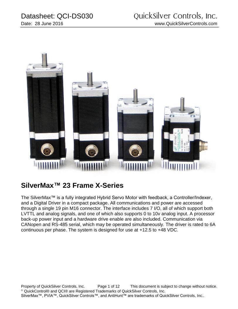
Datasheet: QCI-DS030 QuickSilver Controls, Inc. Date: 28 June 2016 www.QuickSilverControls.com Property of QuickSilver Controls, Inc. Page 1 of 12 This document is subject to change without notice. QuickControl® and QCI® are Registered Trademarks of QuickSilver Controls, Inc. SilverMax™, PVIA™, QuickSilver Controls™, and AntiHunt™ are trademarks of QuickSilver Controls, Inc.. SilverMax™ 23 Frame X-Series The SilverMax™ is a fully integrated Hybrid Servo Motor with feedback, a Controller/Indexer, and a Digital Driver in a compact package. All communications and power are accessed through a single 19 pin M16 connector. The interface includes 7 I/O, all of which support both LVTTL and analog signals, and one of which also supports 0 to 10v analog input. A processor back-up power input and a hardware drive enable are also included. Communication via CANopen and RS-485 serial, which may be operated simultaneously. The driver is rated to 6A continuous per phase. The system is designed for use at +12.5 to +48 VDC.
Transcript of Datasheet: QCI-DS030 QuickSilver Controls, Inc. - MACCON · Datasheet: QCI-DS030 QuickSilver...
Datasheet: QCI-DS030 QuickSilver Controls, Inc. Date: 28 June 2016 www.QuickSilverControls.com
Property of QuickSilver Controls, Inc. Page 1 of 12 This document is subject to change without notice. QuickControl® and QCI® are Registered Trademarks of QuickSilver Controls, Inc. SilverMax™, PVIA™, QuickSilver Controls™, and AntiHunt™ are trademarks of QuickSilver Controls, Inc..
SilverMax™ 23 Frame X-Series The SilverMax™ is a fully integrated Hybrid Servo Motor with feedback, a Controller/Indexer, and a Digital Driver in a compact package. All communications and power are accessed through a single 19 pin M16 connector. The interface includes 7 I/O, all of which support both LVTTL and analog signals, and one of which also supports 0 to 10v analog input. A processor back-up power input and a hardware drive enable are also included. Communication via CANopen and RS-485 serial, which may be operated simultaneously. The driver is rated to 6A continuous per phase. The system is designed for use at +12.5 to +48 VDC.
Datasheet:QCI-DS030 QuickSilver Controls, Inc.
QuickSilver Controls, Inc. Page 2 of 12
System Overview Point-to-Point Moves
Relative or Absolute
Velocity or Time Based
S-Curve Advanced Motion Profile Moves
Profile Move Commands
Register Based o Position/Accel/Decel/Vel o Modify On-the-Fly
Multi-Axis Linear Interpolation
XYZ Coords Contained in Text File
CANopen® used for local bus
1000+ Points Stored in NV Memory Program and Data Storage
32K Non-Volatile Memory:
2000-3000 Program Lines
User Data Examples o CAM Tables o Motion Profiles o Lookup Tables
Electronic Slip Clutch/Brake
Variable Torque
Wind/Unwind Applications Anti-Hunt™
Optionally use Open Loop While Holding
No Servo Dither While at Rest
Communications
RS-485 @ up to 230K Baud
ASCII,Binary,Modbus®,DMX512
Host Control While Servo in Motion
CANopen® (Rev 03 SW and higher) Programming Language
Easy, Menu Driven Interface
Command Parameter Prompts
No Syntax Errors
User Namable I/O and Registers Advance PVIA™ Servo Loop
100:1 Inertial Mismatch
Direct Drive Oversized Inertial Loads o Flywheels/Belt Drives o Typically Without Gearheads
More Stable Than PID Digital 4 Quadrant Vector Drive
DSP Driven for Reduced Noise Multi-Task/Multi-Thread NEMA 23 Frame
o 8000 Counts/Rev Encoder o Up to 280 oz-in (2 Nm)
(continuous)
Datasheet:QCI-DS030 QuickSilver Controls, Inc.
QuickSilver Controls, Inc. Page 3 of 12
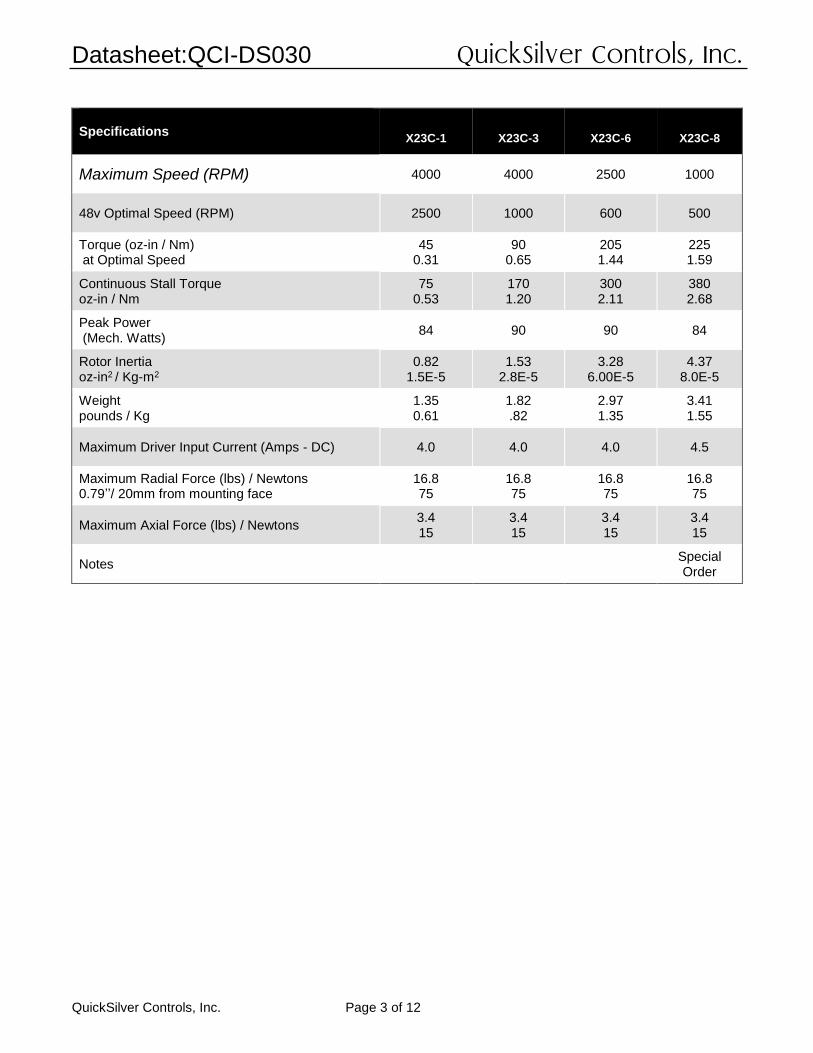
Specifications
X23C-1
X23C-3
X23C-6
X23C-8
Maximum Speed (RPM) 4000 4000 2500 1000
48v Optimal Speed (RPM) 2500 1000 600 500
Torque (oz-in / Nm) at Optimal Speed
45 0.31
90 0.65
205 1.44
225 1.59
Continuous Stall Torque oz-in / Nm
75 0.53
170 1.20
300 2.11
380 2.68
Peak Power (Mech. Watts)
84 90 90 84
Rotor Inertia oz-in2 / Kg-m2
0.82 1.5E-5
1.53 2.8E-5
3.28 6.00E-5
4.37 8.0E-5
Weight pounds / Kg
1.35 0.61
1.82 .82
2.97 1.35
3.41 1.55
Maximum Driver Input Current (Amps - DC) 4.0 4.0 4.0 4.5
Maximum Radial Force (lbs) / Newtons 0.79’’/ 20mm from mounting face
16.8 75
16.8 75
16.8 75
16.8 75
Maximum Axial Force (lbs) / Newtons 3.4 15
3.4 15
3.4 15
3.4 15
Notes Special Order
Datasheet:QCI-DS030 QuickSilver Controls, Inc.
QuickSilver Controls, Inc. Page 4 of 12
0
100
200
300
400
500
600
700
0
10
20
30
40
50
60
70
80
90
100
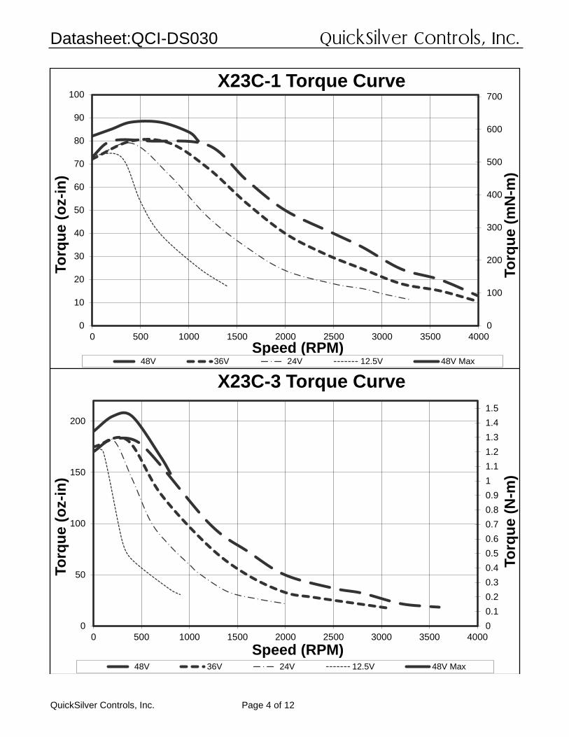
0 500 1000 1500 2000 2500 3000 3500 4000
To
rqu
e (
mN
-m)
To
rqu
e (
oz-i
n)
Speed (RPM)
X23C-1 Torque Curve
48V 36V 24V 12.5V 48V Max
0
0.1
0.2
0.3
0.4
0.5
0.6
0.7
0.8
0.9
1
1.1
1.2
1.3
1.4
1.5
0
50
100
150
200
0 500 1000 1500 2000 2500 3000 3500 4000
To
rqu
e (
N-m
)
To
rqu
e (
oz-i
n)
Speed (RPM)
X23C-3 Torque Curve
48V 36V 24V 12.5V 48V Max
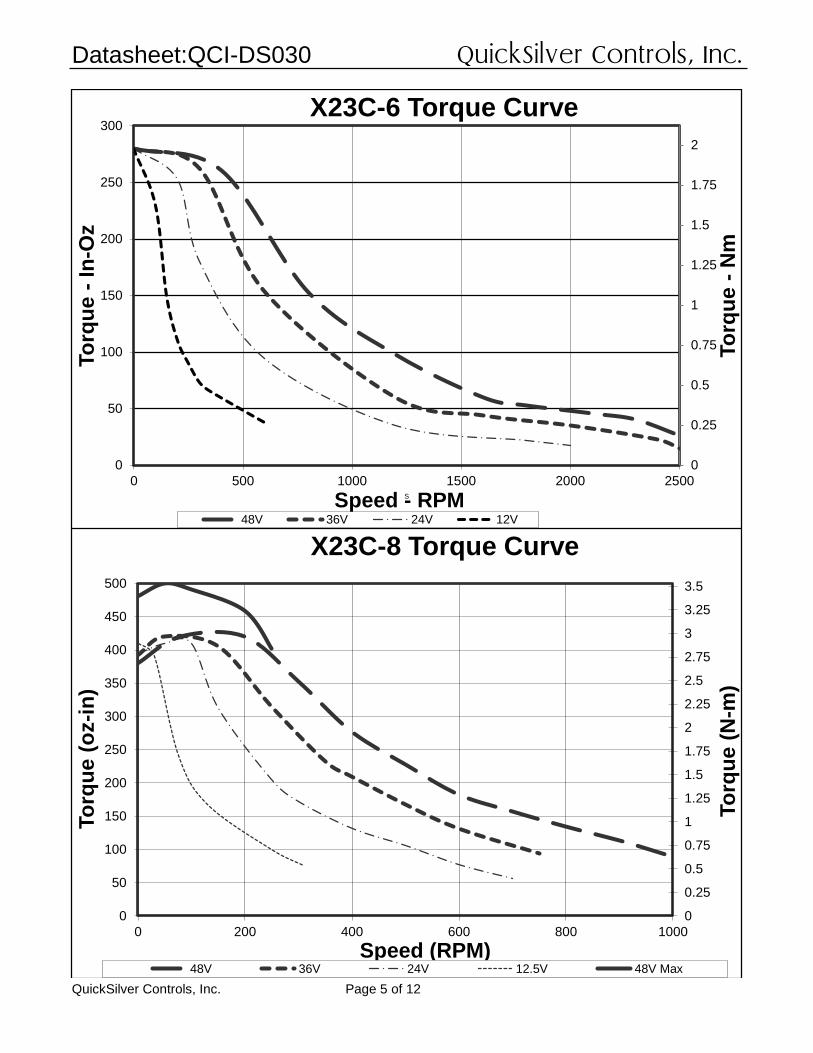
Datasheet:QCI-DS030 QuickSilver Controls, Inc.
QuickSilver Controls, Inc. Page 5 of 12
0
0.25
0.5
0.75
1
1.25
1.5
1.75
2
0
50
100
150
200
250
300
0 500 1000 1500 2000 2500
To
rqu
e -
Nm
Speed - RPM
To
rqu
e -
In-O
z
S
X23C-6 Torque Curve
48V 36V 24V 12V
0
0.25
0.5
0.75
1
1.25
1.5
1.75
2
2.25
2.5
2.75
3
3.25
3.5
0
50
100
150
200
250
300
350
400
450
500
0 200 400 600 800 1000
To
rqu
e (
N-m
)
To
rqu
e (
oz-i
n)
Speed (RPM)
X23C-8 Torque Curve
48V 36V 24V 12.5V 48V Max
Datasheet:QCI-DS030 QuickSilver Controls, Inc.
QuickSilver Controls, Inc. Page 6 of 12
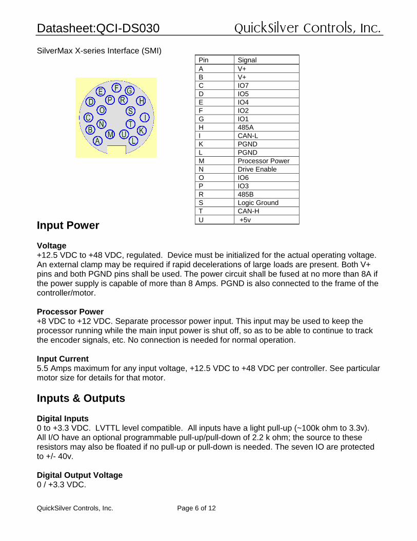
SilverMax X-series Interface (SMI)
Input Power Voltage +12.5 VDC to +48 VDC, regulated. Device must be initialized for the actual operating voltage. An external clamp may be required if rapid decelerations of large loads are present. Both V+ pins and both PGND pins shall be used. The power circuit shall be fused at no more than 8A if the power supply is capable of more than 8 Amps. PGND is also connected to the frame of the controller/motor. Processor Power +8 VDC to +12 VDC. Separate processor power input. This input may be used to keep the processor running while the main input power is shut off, so as to be able to continue to track the encoder signals, etc. No connection is needed for normal operation. Input Current 5.5 Amps maximum for any input voltage, +12.5 VDC to +48 VDC per controller. See particular motor size for details for that motor.
Inputs & Outputs Digital Inputs 0 to +3.3 VDC. LVTTL level compatible. All inputs have a light pull-up (~100k ohm to 3.3v). All I/O have an optional programmable pull-up/pull-down of 2.2 k ohm; the source to these resistors may also be floated if no pull-up or pull-down is needed. The seven IO are protected to +/- 40v. Digital Output Voltage 0 / +3.3 VDC.
Pin Signal
A V+
B V+
C IO7
D IO5
E IO4
F IO2
G IO1
H 485A
I CAN-L
K PGND
L PGND
M Processor Power
N Drive Enable
O IO6
P IO3
R 485B
S Logic Ground
T CAN-H
U +5v
Datasheet:QCI-DS030 QuickSilver Controls, Inc.
QuickSilver Controls, Inc. Page 7 of 12
Digital Output Current Sinking or Sourcing: 2mA Analog Inputs All 7 I/O may be used as Analog Inputs: 0 to +3.3 VDC input signal range. IO7 has a secondary circuit to handle 0 to +10v input signal range; the input protection will isolate the normal 3.3 v input channel allowing the 0 to 10v operation. Resolution: 12 bits (before filtering) Analog signals are read every servo cycle (120 μsec.) and the converted analog data is processed through a (default) 5 ms filter to reduce noise & transients. Drive Enable Input This hardware drive enable input must be connected to +10 VDC to +48 VDC for the drive electronics to operate.
Communications
Serial Interface RS-485 multi-drop, Reduced unit load accommodates up to 255 nodes. Protected up to +/- 70v. Note: RS-485 requires a nominal 120 ohm ½ W termination resistor at each end of the network for longer runs. This termination is not provided onboard and must be provided by the user. Protocols
8-bit ASCII, 9-bit binary, Modbus, and DMX512 Hardware Configuration Settings Available Baud Rates: 2400, 4800, 9600, 19.2k, 28.8k, 57.6k, 115.2k or 230.4k (250k only for DMX512) Data Bits: 8 (9 bits for binary) Stop Bits: 1.5 or 2 Parity Bit: None (Modbus supports None, Even, Odd) CAN interface The CAN bus connection is not isolated, but does include transceivers which have an extended +/- 80v fault protection range. The CANopen® communications protocol allows the unit to function as a master, slave, or peer on a CANopen network. See the CANopen User Manual for details on the CANopen protocol. This protocol operates simultaneously and independently from the standard serial protocols. Note that a 120 ohm ½ W termination resistor is required at each end of the CAN network (only two per system). This termination is not provided onboard the controller and must be provided by the user. For the CAN bus, this termination is not optional. CANopen® and CiA® are registered community trademarks of CAN in Automation e.V.
Datasheet:QCI-DS030 QuickSilver Controls, Inc.
QuickSilver Controls, Inc. Page 8 of 12
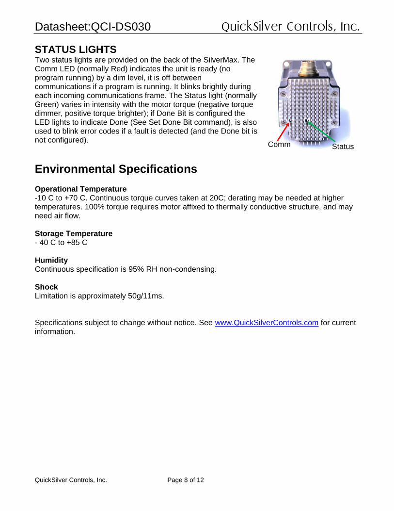
STATUS LIGHTS Two status lights are provided on the back of the SilverMax. The Comm LED (normally Red) indicates the unit is ready (no program running) by a dim level, it is off between communications if a program is running. It blinks brightly during each incoming communications frame. The Status light (normally Green) varies in intensity with the motor torque (negative torque dimmer, positive torque brighter); if Done Bit is configured the LED lights to indicate Done (See Set Done Bit command), is also used to blink error codes if a fault is detected (and the Done bit is not configured).
Environmental Specifications Operational Temperature -10 C to +70 C. Continuous torque curves taken at 20C; derating may be needed at higher temperatures. 100% torque requires motor affixed to thermally conductive structure, and may need air flow. Storage Temperature - 40 C to +85 C Humidity Continuous specification is 95% RH non-condensing. Shock Limitation is approximately 50g/11ms. Specifications subject to change without notice. See www.QuickSilverControls.com for current information.
Comm Status
Datasheet:QCI-DS030 QuickSilver Controls, Inc.
QuickSilver Controls, Inc. Page 9 of 12
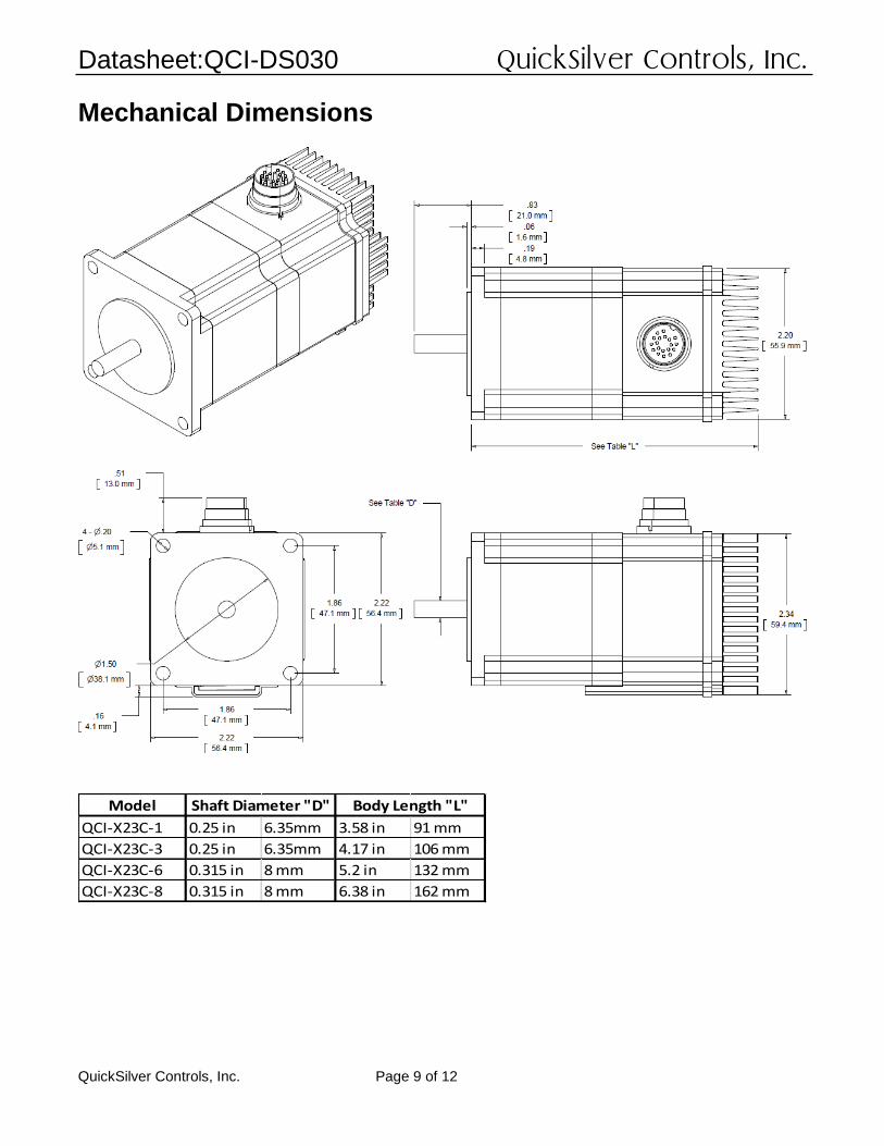
Mechanical Dimensions
Model
QCI-X23C-1 0.25 in 6.35mm 3.58 in 91 mm
QCI-X23C-3 0.25 in 6.35mm 4.17 in 106 mm
QCI-X23C-6 0.315 in 8 mm 5.2 in 132 mm
QCI-X23C-8 0.315 in 8 mm 6.38 in 162 mm
Shaft Diameter "D" Body Length "L"
Datasheet:QCI-DS030 QuickSilver Controls, Inc.
QuickSilver Controls, Inc. Page 10 of 12
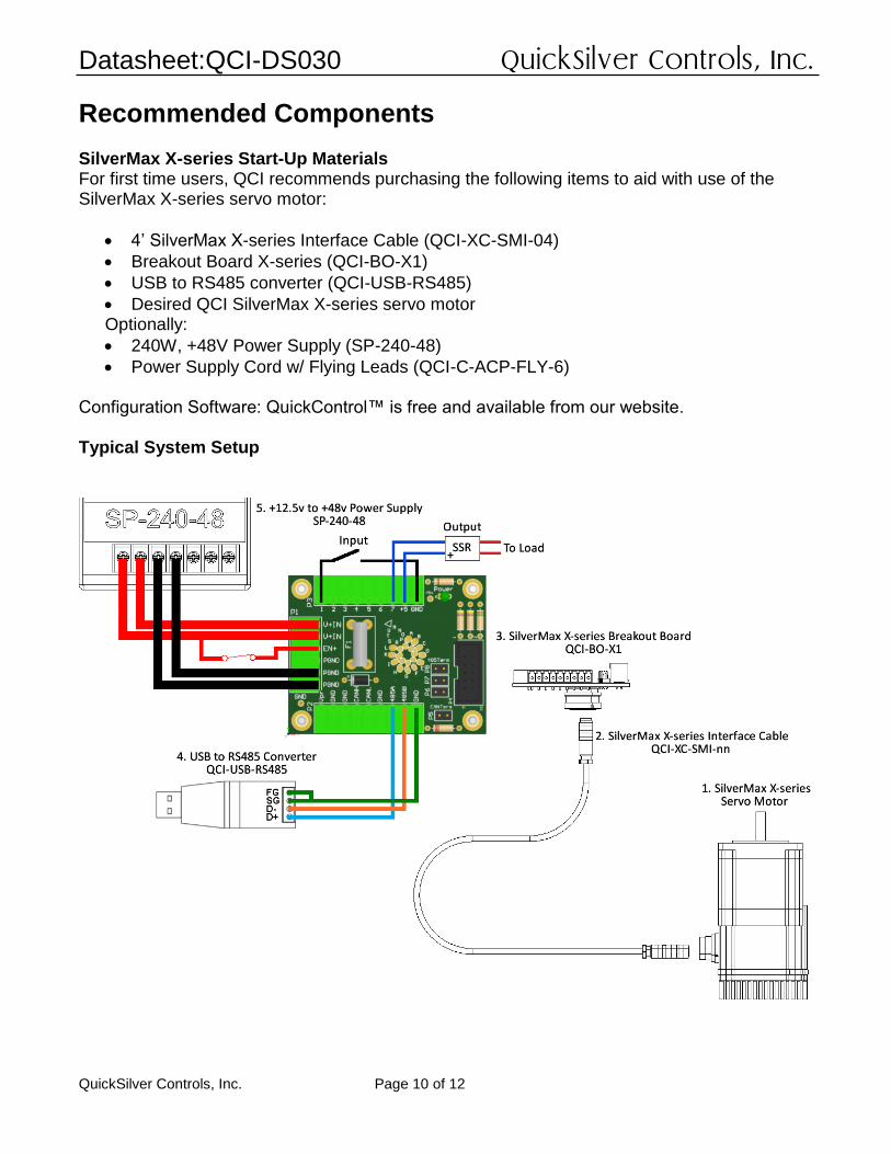
Recommended Components SilverMax X-series Start-Up Materials For first time users, QCI recommends purchasing the following items to aid with use of the SilverMax X-series servo motor:
4’ SilverMax X-series Interface Cable (QCI-XC-SMI-04)
Breakout Board X-series (QCI-BO-X1)
USB to RS485 converter (QCI-USB-RS485)
Desired QCI SilverMax X-series servo motor Optionally:
240W, +48V Power Supply (SP-240-48)
Power Supply Cord w/ Flying Leads (QCI-C-ACP-FLY-6)
Configuration Software: QuickControl™ is free and available from our website. Typical System Setup
Datasheet:QCI-DS030 QuickSilver Controls, Inc.
QuickSilver Controls, Inc. Page 11 of 12
1. SilverMax X-series Servo Motor Motor size based on application requirements. 2. SilverMax X-series Interface Cables The QCI-XC-SMI-nn is used to connect the SilverMax X-series motor to the QCI-BO-X1 breakout board. Replace the last two digits “nn” with length of cable in feet (i.e. –10 for 10 feet). Standard lengths are 4 and 10 feet. The QCI-XC-SMF-nn cable connects to the SMI connector on the SilverMax and provides a pig-tail to allow landing the various signals to your own terminating blocks – see QCI-TD081 for more details. 3. SilverMax X-series Breakout (QCI-BO-X1) QCI recommends purchasing a breakout to simplify wiring power, RS-485 communication, CAN, power backup, drive enable, and 7 LVTTL I/O. The breakouts connect to the SilverMax Interface Cable and includes power fusing. The QCI-BO-X1 is designed to mount through the control housing, providing an IP67 seal for the control housing. See QCI-TD079 for more information. 4. USB to RS485 Converter USB-RS-485 converter provides a USB powered serial port with RS-485 signaling. See QCI-TD073 USB-RS485 Converter Setup Guide for information on network termination and shielding recommendations. 5. Power Supply Power supply selection is motor dependent, but the following will work with all SilverMax X-series 23 frame motors. SP-240-48 (48V, 5A, 240 Watt) 6. External Regenerative Clamp (not shown) Rapid deceleration of larger loads may require a Clamp circuit if the capacitors in the power supply output are not sufficient to hold the recovered energy. Continuous braking of a load also may require the Clamp to handle the generated power. See QCI-TD017 for more information. QCI-CLCF-04-R2
Datasheet:QCI-DS030 QuickSilver Controls, Inc.
QuickSilver Controls, Inc. Page 12 of 12
Part Numbers
SilverMax X- Series NEMA 23 Motor Size
Standard: 8000 CPR Encoder 12.5v to 48v Driver Enable CANopen RS-485 – multiple protocols 19 pin M16 Connector
QCI-X23C-1
QCI-X23C-3
QCI-X23C-6
QCI-X23C-8
Contact Information QuickSilver Controls, Inc. 990 N Amelia Ave San Dimas, CA 91773 +1 (909) 599-6291 or (888) 660-3801 +1 (909) 599-6289 FAX www.QuickSilverControls.com