Database Products IDS/II IDS/II Administrator's...
293
47 A2 13UD Rev01 Database Products IDS/II IDS/II Administrator's Guide Software Subject : This manual provides the Data Base Administrator with detailed information for designing and managing an IDS/II database, and for defining the associated Schema and Subschemas. Special instructions : This Revision 1 cancels and replaces Revision 0 for user's GCOS7 Releases V3 and V5. Software supported : GCOS7-V3 GCOS7-V5 Date : August 1990 Bull Electronics Angers S.A. Bull HN Information Systems Inc. CEDOC Publication Order Entry Atelier de Reprographie FAX: (508) 294-7411 331, Avenue Patton MA02/423S 49004 ANGERS Cedex 01 Technology Park FRANCE Billerica, MA 01821 U.S.A.
Transcript of Database Products IDS/II IDS/II Administrator's...

47 A2 13UD Rev01
Database Products IDS/II
IDS/II Administrator's Guide
Software
Subject : This manual provides the Data Base Administrator with detailedinformation for designing and managing an IDS/II database, and fordefining the associated Schema and Subschemas.
Special instructions : This Revision 1 cancels and replaces Revision 0 for user's GCOS7Releases V3 and V5.
Software supported : GCOS7-V3GCOS7-V5
Date : August 1990
Bull Electronics Angers S.A. Bull HN Information Systems Inc.CEDOC Publication Order EntryAtelier de Reprographie FAX: (508) 294-7411331, Avenue Patton MA02/423S49004 ANGERS Cedex 01 Technology ParkFRANCE Billerica, MA 01821
U.S.A.

47 A2 13UD Rev01
Copyright Bull S.A., 1990
Bull acknowledges the rights of proprietors of trademarks mentioned herein.
Suggestions and criticisms concerning the form, content, and presentation of this manual are invited.A form is provided at the end of this manual for this purpose.
Bull disclaims the implied warranties of merchantability and fitness for a particular purpose and makesno express warranties except as may be stated in its written agreement with and for its customer. Inno event is Bull liable to anyone for any indirect, special, or consequential damages.
The information and specifications in this document are subject to change without notice. Consultyour Bull Marketing Representative for product or service availability.

47 A2 13UD Rev01 iii
Preface
SCOPE AND OBJECTIVES
IDS/II is a set of techniques, utility programs, and specially designed languages whichallow the user to define a database in a accordance with his own requirements. With thetools available in IDS/II, he can create a sophisticated database, and efficiently accessand update that database.
This manual is a companion volume to the Full IDS/II Reference Manual, Volumes I andII, and the Full IDS/II User's Guide. It provides the Database Administrator with detailedinformation for designing and managing an IDS/II database, and for defining theassociated schema and subschemas.
INTENDED READERS
The intended readers of this manual are Database Administrators or other persons whomay be responsible for the efficient operation of the database.
IDS/II Administrator's Guide
iv 47 A2 13UD Rev01
STRUCTURE OF THIS DOCUMENT
This manual is divided into ten sections.
Section 1 provides an overview of the needs and responsibilities of theDatabase Administrator.
Sections 2 and 3 discuss the methods which are to be used by the DatabaseAdministrator to retain optimal performance and integrity inthe operations of the database.
Section 4 describes the preallocation of storage areas and indexes.
Section 5 to 8 provide detailed explanations of the various utilities which areat the disposal of the Database Administrator.
Section 9 describes interactive data manipulation and the DBDIALOGcommands and functions when operating in the IOFenvironment.
Section 10 provides an overview of the internal physical structure of theIDS/II database.
RELATED DOCUMENTS
The manuals listed below provide the information necessary for the use of an IDS/IIdatabase used with GCOS 7 Release V5.
Full IDS/II Reference Manual Volume I ........................................................... 47 A2 05UDFull IDS/II Reference Manual Volume II .......................................................... 47 A2 06UDFull IDS/II User's Guide................................................................................... 47 A2 07UDFull IDS/II Quick Reference Card.................................................................... 47 A2 09UDDatabase Reorganization utility user's Guide ................................................. 47 A2 13UDJCL User's Guide ............................................................................................. 47 A2 12UJIOF Terminal User's Reference Manuel (V3),Part 1................................................................................................................ 47 A2 01UJPart 2............................................................................................................... 47 A2 02UJ/Part 3................................................................................................................ 47 A2 03UJIOF Terminal User's Reference Manuel (V5)Part 1 Introduction............................................................................................ 47 A2 21UJPart 2 GCL Commands (VBO)......................................................................... 47 A2 22UJPart 2 GCL Commands (RBO)......................................................................... 47 A2 23UJPart 3 Directives............................................................................................... 47 A2 24UJCOBOL 85 User's Guide..................................................................................47 A2 06UL

Preface
47 A2 13UD Rev01 v
SYNTAX NOTATION
The notation used in all formats and the rules that apply to all formats are as follows:
• The elements that make up a clause consist of upper case words, lower case words,special symbols, and special characters.
• All underlined upper bold case words are required when the format is used (keywords).Example: TRANSFORM NAME IS transform-name.
• Upper-case not underlined are optional (optional words) and need not be used. In thepreceding example, NAME and IS are optional.
• Lower-case words are generic terms that must be replaced by appropriate names orvalues. In the preceding example schema-name must be replaced by the user-definedname for the schema.
• The meaning of enclosing a portion of a general format in special symbols is as follows:
Optional, no selection needed.
[a] at least no occurences [b] [c] at most one occurence
Required, must select one.
{a} at least one occurence {b} {c} at most one occurence
Required, must select one at least one.
||a|| at least one occurence ||b|| ||c|| at most one occurence
An ellipsis (that is, ...) indicates that repetition is allowed. The portion of the format thatcan be repeated is determined by the bracket ([) or brace ({) which logically matches thebracket (]) or brace (}) to the immediate left of the ellipsis.

IDS/II Administrator's Guide
vi 47 A2 13UD Rev01

47 A2 13UD Rev01 vii
Table of Contents
1. Introduction ........................................................................................................... 1-1
1.1 OVERVIEW OF THE DATABASE ADMINISTRATOR'SRESPONSIBILITIES ................................................................................................... 1-1
1.2 ENTITIES REFERENCED BY THE DATABASE UTILITY ........................................ 1-3
1.2.1 IDS/II Step Files ......................................................................................................... 1-31.2.2 Command Files ......................................................................................................... 1-31.2.3 Report Files ................................................................................................................ 1-41.2.4 Other Files .................................................................................................................. 1-4
1.3 MNDB GCL STATEMENT .......................................................................................... 1-5
1.4 JCL OF THE DATABASE UTILITY ............................................................................ 1-6
1.4.1 Parameter Description .............................................................................................. 1-6
1.5 COMMAND LANGUAGE OF THE DATABASE UTILITY .......................................... 1-8
1.5.1 Command Language Syntax .................................................................................... 1-81.5.2 Types of Command ................................................................................................... 1-81.5.3 Reserved Words ........................................................................................................ 1-10
1.6 EXECUTION ENVIRONMENT OF THE DATABASE UTILITY .................................. 1-14
1.6.1 BATCH Operability .................................................................................................... 1-151.6.2 IOF Operability ........................................................................................................... 1-17
1.7 CONCURRENT ACCESS IN THE DATABASE UTILITY .......................................... 1-21
1.7.1 Usage Modes for Areas and Indexes ...................................................................... 1-211.7.2 Commitment-points .................................................................................................. 1-21

IDS/II Administrator's Guide
viii 47 A2 13UD Rev01
2. Performance and Evolution of the Database .......................................... 2-1
2.1 STRUCTURE OF A DATABASE ................................................................................ 2-2
2.1.1 Compromise Between Applications ........................................................................ 2-22.1.2 Physically Reorganizing the Database ................................................................... 2-3
2.2 CONCURRENT ACCESS ........................................................................................... 2-4
2.2.1 SHARED RETRIEVAL Usage Mode .......................................................................... 2-42.2.2 MONITORED Usage Mode ........................................................................................ 2-42.2.3 TDS Environment ...................................................................................................... 2-42.2.4 IOF Environment ....................................................................................................... 2-52.2.5 BATCH Environment ................................................................................................. 2-52.2.6 All Environments ....................................................................................................... 2-5
2.3 JOURNALS ................................................................................................................. 2-6
2.3.1 BEFORE Journal ....................................................................................................... 2-62.3.2 AFTER Journal .......................................................................................................... 2-6
2.4 BUFFER STRATEGY ................................................................................................. 2-7
2.4.1 Run-time Parameters ................................................................................................ 2-72.4.2 BATCH/IOF Mono-Step Case ................................................................................... 2-72.4.3 BATCH/IOF Multi-Step Case ..................................................................................... 2-92.4.4 TDS Case (See Figure 2-4) ....................................................................................... 2-10
2.5 RUN-TIME MONITORING OPTIONS......................................................................... 2-12
2.6 INITIAL DATABASE LOADING .................................................................................. 2-13
2.6.1 Mass Loading of Permanent Records ..................................................................... 2-132.6.2 Loading of CALC Records that are not AUTOMATIC
Members of any Set .................................................................................................. 2-132.6.3 Loading of Members of Sorted Sets Without
NO-DUPLICATE-CONTROL-FIELDS ........................................................................ 2-142.6.4 Building of Secondary Keys ..................................................................................... 2-152.6.5 Use of a Temporary Loading Schema ..................................................................... 2-15

Table of Contents
47 A2 13UD Rev01 ix
3. Database Integrity ............................................................................................... 3-1
3.1 THREATS TO DATABASE INTEGRITY .................................................................... 3-1
3.2 FILSAVE, FILREST AND FILDUPLI UTILITIES_ ...................................................... 3-2
3.3 BEFORE JOURNAL ................................................................................................... 3-4
3.4 AFTER JOURNAL ...................................................................................................... 3-8
3.5 AREA AND INDEX STATUS INDICATORS ............................................................... 3-11
3.5.1 TRANSIENT State Indicator ...................................................................................... 3-113.5.2 INCONSISTENT State Indicator ............................................................................... 3-11
3.6 DATABASE VALIDITY CHECKS ............................................................................... 3-13
3.6.1 DBCS Validity Checks ............................................................................................... 3-133.6.2 DBUTILITY Validity Checks ...................................................................................... 3-133.6.3 User Validity Checks ................................................................................................. 3-14
3.7 DATABASE PATCH FACILITY .................................................................................. 3-15
4. The Preallocation of Areas and Indexes ................................................... 4-1
4.1 PREALLOC UTILITY .................................................................................................. 4-1
4.2 SPACE ALLOCATION ................................................................................................ 4-3
4.3 PREALLOC GCL STATEMENT ................................................................................. 4-4
4.3.1 Parameter Description .............................................................................................. 4-5
4.4 PREALLOC EXTENDED JCL STATEMENT ............................................................. 4-7
4.4.1 PREALLOC General Format ..................................................................................... 4-74.4.2 PREALLOC Parameter Description ......................................................................... 4-8

IDS/II Administrator's Guide
x 47 A2 13UD Rev01
5. Database Utility Common Functions .......................................................... 5-1
5.1 DBUTILITY COMMON FUNCTIONS ......................................................................... 5-1
5.2 DBUTILITY COMMON COMMAND LANGUAGE ...................................................... 5-2
5.2.1 Syntax Conventions .................................................................................................. 5-25.2.2 Types of command ................................................................................................... 5-2
5.3 DISPLAY COMMAND ................................................................................................. 5-3
5.3.1 Function ..................................................................................................................... 5-35.3.2 General Format .......................................................................................................... 5-35.3.3 Rules ........................................................................................................................... 5-3
5.4 SCHEMA COMMAND ................................................................................................. 5-4
5.4.1 Function ..................................................................................................................... 5-45.4.2 General Format .......................................................................................................... 5-45.4.3 Rules ........................................................................................................................... 5-4
5.5 COMMIT COMMAND ................................................................................................. 5-5
5.5.1 Functions ................................................................................................................... 5-55.5.2 General Format .......................................................................................................... 5-55.5.3 Syntax Rules .............................................................................................................. 5-55.5.4 General Rules ............................................................................................................ 5-5
5.6 ROLLBACK COMMAND ............................................................................................ 5-7
5.6.1 Function ..................................................................................................................... 5-75.6.2 General Format .......................................................................................................... 5-75.6.3 Rules ........................................................................................................................... 5-7
5.7 STATUS COMMAND .................................................................................................. 5-8
5.7.1 Function ..................................................................................................................... 5-85.7.2 General Format .......................................................................................................... 5-85.7.3 Rules ........................................................................................................................... 5-8
5.8 OPTION COMMAND .................................................................................................. 5-10
5.8.1 Function ..................................................................................................................... 5-105.8.2 General Format .......................................................................................................... 5-105.8.3 Rules ........................................................................................................................... 5-10

Table of Contents
47 A2 13UD Rev01 xi
5.9 HELP COMMAND ...................................................................................................... 5-11
5.9.1 Function ..................................................................................................................... 5-115.9.2 General Format .......................................................................................................... 5-115.9.3 Rules ........................................................................................................................... 5-11
5.10 QUIT COMMAND ....................................................................................................... 5-12
5.10.1 Function ..................................................................................................................... 5-125.10.2 General format ........................................................................................................... 5-125.10.3 Rules ........................................................................................................................... 5-12
6. Database Print Functions ................................................................................ 6-1
6.1 DBPRINT FUNCTIONS .............................................................................................. 6-1
6.2 DBPRINT COMMAND LANGUAGE ........................................................................... 6-2
6.2.1 Syntax Conventions .................................................................................................. 6-26.2.2 Types of Command ................................................................................................... 6-2
6.3 PRINT RECORD COMMAND WITH SELECTION BY AREA-KEY ........................... 6-3
6.3.1 Function ..................................................................................................................... 6-36.3.2 General Format .......................................................................................................... 6-36.3.3 Syntax Rules .............................................................................................................. 6-46.3.4 General rules ............................................................................................................. 6-4
6.4 PRINT RECORD COMMAND WITH SELECTION BY CALC-KEY ........................... 6-8
6.4.1 Function ..................................................................................................................... 6-86.4.2 General Format .......................................................................................................... 6-86.4.3 Syntax Rules .............................................................................................................. 6-86.4.4 General Rules ............................................................................................................ 6-9
6.5 PRINT RECORD COMMAND WITH SELECTION BYSET-PARTICIPATION ................................................................................................ 6-10
6.5.1 Function ..................................................................................................................... 6-106.5.2 General Format .......................................................................................................... 6-106.5.3 Syntax Rules .............................................................................................................. 6-116.5.4 General Rules ............................................................................................................ 6-11
6.6 PRINT PAGE COMMAND .......................................................................................... 6-14
6.6.1 Function ..................................................................................................................... 6-14

IDS/II Administrator's Guide
xii 47 A2 13UD Rev01
6.6.2 General Format .......................................................................................................... 6-146.6.3 Syntax Rules .............................................................................................................. 6-146.6.4 General Rules ............................................................................................................ 6-14
6.7 PRINT LABEL COMMAND ........................................................................................ 6-18
6.7.1 Function ..................................................................................................................... 6-186.7.2 General Format .......................................................................................................... 6-186.7.3 General Rules ............................................................................................................ 6-18
6.8 CONSIDERATIONS FOR A CONCURRENT ACCESS ENVIRONMENT ................. 6-21
6.9 EXAMPLES OF DBPRINT .......................................................................................... 6-23
7. Database Analysis Functions ........................................................................ 7-1
7.1 DBANALYS FUNCTIONS .......................................................................................... 7-1
7.2 DBANALYS COMMAND LANGUAGE ....................................................................... 7-2
7.2.1 Syntax Conventions .................................................................................................. 7-27.2.2 Types of Command ................................................................................................... 7-2
7.3 ANALYSE AREA COMMAND .................................................................................... 7-3
7.3.1 Function ..................................................................................................................... 7-37.3.2 General Format .......................................................................................................... 7-37.3.3 Syntax Rules .............................................................................................................. 7-47.3.4 General Rules ............................................................................................................ 7-4
7.4 ANALYSE INDEX COMMAND ................................................................................... 7-12
7.4.1 Function ..................................................................................................................... 7-127.4.2 General Format .......................................................................................................... 7-127.4.3 Syntax Rules .............................................................................................................. 7-127.4.4 General Rules ............................................................................................................ 7-13
7.5 SIMULOAD COMMAND ............................................................................................. 7-20
7.5.1 Function ..................................................................................................................... 7-207.5.2 General Format .......................................................................................................... 7-227.5.3 Syntax Rules .............................................................................................................. 7-227.5.4 General Rules ............................................................................................................ 7-23

Table of Contents
47 A2 13UD Rev01 xiii
7.6 SIMULATION INPUT FORMAT .................................................................................. 7-27
7.7 SORT COMMAND ...................................................................................................... 7-28
7.7.1 Function ..................................................................................................................... 7-287.7.2 General Format .......................................................................................................... 7-287.7.3 Syntax Rules .............................................................................................................. 7-287.7.4 General Rules ............................................................................................................ 7-28
7.8 CONDITIONS IN A CONCURRENT ACCESS ENVIRONMENT ............................... 7-30
7.9 PERFORMANCE ASPECTS ...................................................................................... 7-31
7.9.1 DBUTILITY Work-files ............................................................................................... 7-317.9.2 VMM WORK FILE ....................................................................................................... 7-317.9.3 SORT WORK FILE ..................................................................................................... 7-327.9.4 Hints for Use .............................................................................................................. 7-32
7.10 DBANALYS EXAMPLES ............................................................................................ 7-36
8. Database Validate and Patch Function ..................................................... 8-1
8.1 DBVALID FUNCTIONS .............................................................................................. 8-1
8.2 DBVALID COMMAND LANGUAGE ........................................................................... 8-3
8.2.1 Syntax Conventions .................................................................................................. 8-38.2.2 Types of Command ................................................................................................... 8-3
8.3 VALIDATE POINTERS COMMAND ........................................................................... 8-4
8.3.1 Function ..................................................................................................................... 8-48.3.2 General Format .......................................................................................................... 8-48.3.3 Rules ........................................................................................................................... 8-48.3.4 Interpretation of the VALIDATE POINTERS Report ............................................... 8-5
8.4 VALIDATE PAGE COMMAND ................................................................................... 8-15
8.4.1 Functions ................................................................................................................... 8-158.4.2 General Format .......................................................................................................... 8-158.4.3 Syntax Rules .............................................................................................................. 8-158.4.4 General Rules ............................................................................................................ 8-16

IDS/II Administrator's Guide
xiv 47 A2 13UD Rev01
8.5 VALIDATE CALC-CHAINS COMMAND .................................................................... 8-19
8.5.1 Function ..................................................................................................................... 8-198.5.2 General Format .......................................................................................................... 8-198.5.3 General Rules ............................................................................................................ 8-198.5.4 Interpretation of the VALIDATE CALC-CHAINS Report ......................................... 8-20
8.6 VALIDATE CHECK CLAUSES FOR RECORD COMMAND ..................................... 8-27
8.6.1 Functions ................................................................................................................... 8-278.6.2 General Format .......................................................................................................... 8-278.6.3 Syntax Rules .............................................................................................................. 8-288.6.4 General Rules ............................................................................................................ 8-288.6.5 Interpretation of the VALIDATE CHECK Report ..................................................... 8-29
8.7 PATCH RECORD COMMAND ................................................................................... 8-30
8.7.1 Function ..................................................................................................................... 8-308.7.2 General Format .......................................................................................................... 8-308.7.3 Syntax Rules .............................................................................................................. 8-318.7.4 General Rules ............................................................................................................ 8-32
8.8 PATCH PAGE COMMAND ......................................................................................... 8-34
8.8.1 Function ..................................................................................................................... 8-348.8.2 General Format .......................................................................................................... 8-348.8.3 Syntax Rules .............................................................................................................. 8-348.8.4 General Rules ............................................................................................................ 8-35
8.9 PATCH LABEL COMMAND ....................................................................................... 8-36
8.9.1 Function ..................................................................................................................... 8-368.9.2 General Format .......................................................................................................... 8-368.9.3 Syntax Rules .............................................................................................................. 8-368.9.4 General Rules ............................................................................................................ 8-37
8.10 RECONNECT RECORD COMMAND......................................................................... 8-38
8.10.1 Function ..................................................................................................................... 8-388.10.2 General Format .......................................................................................................... 8-388.10.3 Syntax Rules .............................................................................................................. 8-398.10.4 General Rules ............................................................................................................ 8-39
8.11 BUILD-KEY COMMAND ............................................................................................ 8-41
8.11.1 Function ..................................................................................................................... 8-418.11.2 General Format .......................................................................................................... 8-418.11.3 General Rules ............................................................................................................ 8-418.11.4 Execution ................................................................................................................... 8-42

Table of Contents
47 A2 13UD Rev01 xv
8.12 DELETE-KEY COMMAND ......................................................................................... 8-43
8.12.1 Function ..................................................................................................................... 8-438.12.2 General format ........................................................................................................... 8-438.12.3 General Rules ............................................................................................................ 8-438.12.4 Execution ................................................................................................................... 8-44
8.13 CONDITIONS IN A CONCURRENT ACCESS ENVIRONMENT ............................... 8-45
8.14 PERFORMANCE ASPECTS (VALIDATE COMMAND) ............................................. 8-47
8.15 DBVALID EXAMPLES ................................................................................................ 8-48
9. Interactive Data Manipulation Functions .................................................. 9-1
9.1 DBDIALOG FUNCTIONS ........................................................................................... 9-1
9.2 DBDIALOG COMMAND LANGUAGE ....................................................................... 9-2
9.2.1 Syntax Conventions .................................................................................................. 9-29.2.2 The Definition of a Working Storage Variable ........................................................ 9-29.2.3 Types of command ................................................................................................... 9-29.2.4 Execution of DBDIALOG commands ...................................................................... 9-3
9.3 SUBSCHEMA COMMAND ......................................................................................... 9-4
9.3.1 Function ..................................................................................................................... 9-49.3.2 General Format .......................................................................................................... 9-49.3.3 Rules ........................................................................................................................... 9-4
9.4 MOVE COMMAND ..................................................................................................... 9-5
9.4.1 Functions ................................................................................................................... 9-59.4.2 Format 1 ..................................................................................................................... 9-59.4.3 Rules ........................................................................................................................... 9-59.4.4 Format 2 ..................................................................................................................... 9-69.4.5 Rules ........................................................................................................................... 9-69.4.6 Format 3 ..................................................................................................................... 9-69.4.7 Rules ........................................................................................................................... 9-79.4.8 Format 4 ..................................................................................................................... 9-79.4.9 Rules ........................................................................................................................... 9-79.4.10 Format 5 ..................................................................................................................... 9-89.4.11 Rules ........................................................................................................................... 9-8
IDS/II Administrator's Guide
xvi 47 A2 13UD Rev01
9.5 LIST COMMAND ........................................................................................................ 9-10
9.5.1 Function ..................................................................................................................... 9-109.5.2 Format 1 ..................................................................................................................... 9-109.5.3 Rules ........................................................................................................................... 9-109.5.4 Format 2 ..................................................................................................................... 9-119.5.5 Rules ........................................................................................................................... 9-129.5.6 Format 3 ..................................................................................................................... 9-139.5.7 Rules ........................................................................................................................... 9-14
9.6 ACCEPT COMMAND ................................................................................................. 9-16
9.6.1 Functions ................................................................................................................... 9-169.6.2 General Format .......................................................................................................... 9-169.6.3 Syntax Rules .............................................................................................................. 9-179.6.4 General Rules and DB-STATUS Values .................................................................. 9-18
9.7 CONNECT COMMAND .............................................................................................. 9-19
9.7.1 Function ..................................................................................................................... 9-199.7.2 General Format .......................................................................................................... 9-199.7.3 Rules and DB-STATUS values ................................................................................. 9-19
9.8 DISCONNECT COMMAND ........................................................................................ 9-20
9.8.1 Function ..................................................................................................................... 9-209.8.2 General Format .......................................................................................................... 9-209.8.3 Rules and DB-STATUS values ................................................................................. 9-20
9.9 ERASE COMMAND .................................................................................................... 9-21
9.9.1 Function ..................................................................................................................... 9-219.9.2 General Format .......................................................................................................... 9-219.9.3 Rules and DB-STATUS values ................................................................................. 9-21
9.10 FIND COMMAND ........................................................................................................ 9-22
9.10.1 Function ..................................................................................................................... 9-229.10.2 General Format .......................................................................................................... 9-229.10.3 Format 1 ..................................................................................................................... 9-229.10.4 Rules ........................................................................................................................... 9-229.10.5 Format 2 ..................................................................................................................... 9-239.10.6 Rules ........................................................................................................................... 9-239.10.7 Format 3 ..................................................................................................................... 9-239.10.8 Rules ........................................................................................................................... 9-239.10.9 Format 4 ..................................................................................................................... 9-239.10.10 Rules ........................................................................................................................... 9-239.10.11 Format 5 ..................................................................................................................... 9-249.10.12 Rules ........................................................................................................................... 9-249.10.13 Format 6 ..................................................................................................................... 9-249.10.14 Rules ........................................................................................................................... 9-24
Table of Contents
47 A2 13UD Rev01 xvii
9.10.15 Format 7 ..................................................................................................................... 9-259.10.16 Rules ........................................................................................................................... 9-259.10.17 Format 8 ..................................................................................................................... 9-259.10.18 Rules ........................................................................................................................... 9-259.10.19 Format 9 ..................................................................................................................... 9-259.10.20 Rules ........................................................................................................................... 9-259.10.21 DB-STATUS Values ................................................................................................... 9-26
9.11 FINISH COMMAND .................................................................................................... 9-27
9.11.1 Function ..................................................................................................................... 9-279.11.2 General Format .......................................................................................................... 9-279.11.3 Rules and DB-STATUS values ................................................................................. 9-27
9.12 GET COMMAND......................................................................................................... 9-28
9.12.1 Function ..................................................................................................................... 9-289.12.2 General Format .......................................................................................................... 9-289.12.3 Syntax Rules .............................................................................................................. 9-289.12.4 General Rules and DB-STATUS values ................................................................... 9-28
9.13 MODIFY COMMAND .................................................................................................. 9-30
9.13.1 Function ..................................................................................................................... 9-309.13.2 General Format .......................................................................................................... 9-309.13.3 Syntax Rules .............................................................................................................. 9-319.13.4 General Rules and DB-STATUS values ................................................................... 9-31
9.14 READY COMMAND .................................................................................................... 9-32
9.14.1 Function ..................................................................................................................... 9-329.14.2 General Format .......................................................................................................... 9-329.14.3 Rules and DB-STATUS values ................................................................................. 9-32
9.15 STORE COMMAND .................................................................................................... 9-33
9.15.1 Function ..................................................................................................................... 9-339.15.2 General Format .......................................................................................................... 9-339.15.3 Rules and DB-STATUS Values ................................................................................. 9-33
10. The Format of the Database ........................................................................... 10-1
10.1 INTRODUCTION......................................................................................................... 10-1
10.2 OVERVIEW OF THE IDS/II PAGE STRUCTURE ...................................................... 10-2
IDS/II Administrator's Guide
xviii 47 A2 13UD Rev01
10.2.1 Storage Areas ............................................................................................................ 10-210.2.2 Index Files .................................................................................................................. 10-3
10.3 OVERVIEW OF THE CALC CHAIN MECHANISM(STORAGE AREA) ..................................................................................................... 10-6
10.3.1 IDS/II Representation of the CALC Chain ............................................................... 10-610.3.2 Records Connected in the CALC Chain .................................................................. 10-810.3.3 Sets Involved in the CALC Chain ............................................................................ 10-8
10.4 FORMAT OF THE PAGE HEADER ........................................................................... 10-9
10.4.1 Storage Areas ............................................................................................................ 10-910.4.1.1 Format......................................................................................................................... 10-910.4.1.2 Meaning of the Parts of the Header ............................................................................ 10-9
10.5 THE FORMAT OF STORAGE RECORDS (STORAGE AREA) ................................. 10-11
10.5.1 Non-CALC Records ................................................................................................... 10-1110.5.1.1 Format......................................................................................................................... 10-1110.5.1.2 Meaning of the Parts of the Page Header Format ...................................................... 10-11
10.5.2 CALC Records ........................................................................................................... 10-1310.5.2.1 Format......................................................................................................................... 10-1310.5.2.2 Meaning of the Parts of the CALC Record Format ..................................................... 10-13
10.6 FORMAT OF THE LOCATOR ARRAY (STORAGE AREA) ...................................... 10-15
10.6.1 Format ........................................................................................................................ 10-1510.6.2 Meaning of the Parts of the Locator Array Format ................................................ 10-16
10.7 THE FORMAT OF THE CALC CHAIN OWL RECORD(STORAGE AREA) ..................................................................................................... 10-17
10.7.1 Format ........................................................................................................................ 10-1710.7.2 Meaning of the Parts of the CALC Chain OWL Record ......................................... 10-17
10.8 DYNAMIC ASPECTS OF PAGE MANAGEMENT ..................................................... 10-19
10.8.1 Historical Background .............................................................................................. 10-1910.8.2 Physical Placement of a Record in a Page ............................................................. 10-1910.8.3 Assignment of an Area-key to a DIRECT Storage Record
(STORE) ..................................................................................................................... 10-2010.8.4 Assignment of an Area-key to a VIA Storage Record (STORE) ............................ 10-2010.8.5 Assignment of an Area-key to a CALC Storage Record (STORE) ........................ 10-2110.8.6 Assignment of an Area-key to a CALC Storage Record
(MODIFY CALC-key) .................................................................................................. 10-2210.8.7 Deletion of OWL Records
(Page Reorganization, FIND ANY/DUPLICATE) ...................................................... 10-22

Table of Contents
47 A2 13UD Rev01 xix
10.9 OVERVIEW OF IDS/II LABELS .................................................................................. 10-23
10.9.1 THE FORMAT OF THE DIRECTORY IN THE IDS/II LABEL .................................... 10-2510.9.1.1 Format......................................................................................................................... 10-2510.9.1.2 Meaning of the Parts of the IDS/II Label ..................................................................... 10-26
10.9.2 FORMAT OF REGION 1 OF THE IDS/II LABEL ....................................................... 10-2710.9.2.1 Format......................................................................................................................... 10-2710.9.2.2 Meaning of the Parts of Region 1................................................................................ 10-28
10.9.3 THE FORMAT OF REGION 2 OF THE IDS/II LABEL ............................................... 10-2910.9.3.1 Format......................................................................................................................... 10-2910.9.3.2 Meaning of the Parts of Region 2................................................................................ 10-29

IDS/II Administrator's Guide
xx 47 A2 13UD Rev01
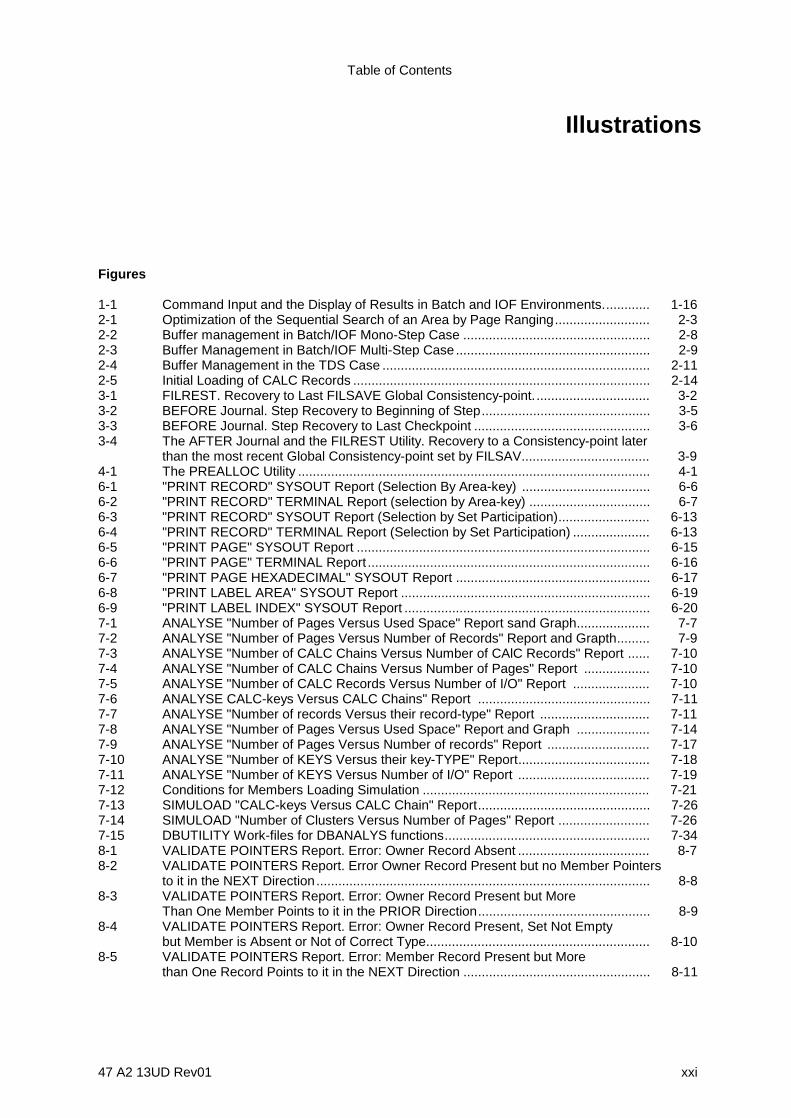
Table of Contents
47 A2 13UD Rev01 xxi
Illustrations
Figures
1-1 Command Input and the Display of Results in Batch and IOF Environments............. 1-162-1 Optimization of the Sequential Search of an Area by Page Ranging.......................... 2-32-2 Buffer management in Batch/IOF Mono-Step Case ................................................... 2-82-3 Buffer Management in Batch/IOF Multi-Step Case..................................................... 2-92-4 Buffer Management in the TDS Case ......................................................................... 2-112-5 Initial Loading of CALC Records ................................................................................. 2-143-1 FILREST. Recovery to Last FILSAVE Global Consistency-point................................ 3-23-2 BEFORE Journal. Step Recovery to Beginning of Step.............................................. 3-53-3 BEFORE Journal. Step Recovery to Last Checkpoint ................................................ 3-63-4 The AFTER Journal and the FILREST Utility. Recovery to a Consistency-point later
than the most recent Global Consistency-point set by FILSAV................................... 3-94-1 The PREALLOC Utility ................................................................................................ 4-16-1 "PRINT RECORD" SYSOUT Report (Selection By Area-key) ................................... 6-66-2 "PRINT RECORD" TERMINAL Report (selection by Area-key) ................................. 6-76-3 "PRINT RECORD" SYSOUT Report (Selection by Set Participation)......................... 6-136-4 "PRINT RECORD" TERMINAL Report (Selection by Set Participation) ..................... 6-136-5 "PRINT PAGE" SYSOUT Report ................................................................................ 6-156-6 "PRINT PAGE" TERMINAL Report ............................................................................. 6-166-7 "PRINT PAGE HEXADECIMAL" SYSOUT Report ..................................................... 6-176-8 "PRINT LABEL AREA" SYSOUT Report .................................................................... 6-196-9 "PRINT LABEL INDEX" SYSOUT Report ................................................................... 6-207-1 ANALYSE "Number of Pages Versus Used Space" Report sand Graph.................... 7-77-2 ANALYSE "Number of Pages Versus Number of Records" Report and Grapth......... 7-97-3 ANALYSE "Number of CALC Chains Versus Number of CAlC Records" Report ...... 7-107-4 ANALYSE "Number of CALC Chains Versus Number of Pages" Report .................. 7-107-5 ANALYSE "Number of CALC Records Versus Number of I/O" Report ..................... 7-107-6 ANALYSE CALC-keys Versus CALC Chains" Report ............................................... 7-117-7 ANALYSE "Number of records Versus their record-type" Report .............................. 7-117-8 ANALYSE "Number of Pages Versus Used Space" Report and Graph .................... 7-147-9 ANALYSE "Number of Pages Versus Number of records" Report ............................ 7-177-10 ANALYSE "Number of KEYS Versus their key-TYPE" Report.................................... 7-187-11 ANALYSE "Number of KEYS Versus Number of I/O" Report .................................... 7-197-12 Conditions for Members Loading Simulation .............................................................. 7-217-13 SIMULOAD "CALC-keys Versus CALC Chain" Report............................................... 7-267-14 SIMULOAD "Number of Clusters Versus Number of Pages" Report ......................... 7-267-15 DBUTILITY Work-files for DBANALYS functions........................................................ 7-348-1 VALIDATE POINTERS Report. Error: Owner Record Absent .................................... 8-78-2 VALIDATE POINTERS Report. Error Owner Record Present but no Member Pointers
to it in the NEXT Direction........................................................................................... 8-88-3 VALIDATE POINTERS Report. Error: Owner Record Present but More
Than One Member Points to it in the PRIOR Direction............................................... 8-98-4 VALIDATE POINTERS Report. Error: Owner Record Present, Set Not Empty
but Member is Absent or Not of Correct Type............................................................. 8-108-5 VALIDATE POINTERS Report. Error: Member Record Present but More
than One Record Points to it in the NEXT Direction ................................................... 8-11
IDS/II Administrator's Guide
xxii 47 A2 13UD Rev01
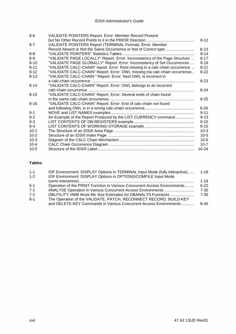
8-6 VALIDATE POINTERS Report. Error: Member Record Presentbut No Other Record Points to it in the PRIOR Direction............................................ 8-12
8-7 VALIDATE POINTERS Report (TERMINAL Format). Error: MemberRecord Absent or Not the Same Occurrence or Not of Correct type .......................... 8-13
8-8 "VALIDATE POINTERS" Statistics Tables. ................................................................ 8-148-9 "VALIDATE PAGE LOCALLY" Report. Error: Inconsistency of the Page Structure ... 8-178-10 "VALIDATE PAGE GLOBALLY" Report. Error: Inconsistency of Set Occurrences ... 8-188-11 "VALIDATE CALC-CHAIN" report. Error: Root missing in a calc-chain occurrence .. 8-218-12 "VALIDATE CALC-CHAIN" Report. Error: OWL missing ina calc-chain occurrence.. 8-228-13 "VALIDATE CALC-CHAIN " Report. Error: Next OWL is incorrect in
a calc-chain occurrence ............................................................................................. 8-238-14 "VALIDATE CALC-CHAIN" Report. Error: OWL belongs to an incorrect
calc-chain occurrence ................................................................................................ 8-248-15 "VALIDATE CALC-CHAIN" Report. Error: Several ends of chain found
in the same calc-chain occurrence.............................................................................. 8-258-16 "VALIDATE CALC-CHAIN" Report. Error: End of calc-chain not found
and following OWL is in a wrong calc-chain occurrence............................................. 8-269-1 MOVE and LIST NAMES examples............................................................................ 9-119-2 An Example of the Report Produced by the LIST CURRENCY command................. 9-139-3 LIST CONTENTS OF DB-REGISTERS example ....................................................... 9-159-4 LIST CONTENTS OF WORKING-STORAGE example ............................................. 9-1510-1 The Structure of an IDS/II Area Page ......................................................................... 10-310-2 Structure of an IDS/II Index Page ............................................................................... 10-510-3 Diagram of the CALC Chain Mechanism .................................................................... 10-610-4 CALC Chain Occurrence Diagram .............................................................................. 10-710-5 Structure of the IDS/II Label ........................................................................................ 10-24
Tables
1-1 IOF Environment: DISPLAY Options in TERMINAL Input Mode (fully interactive) ..... 1-181-2 IOF Environment: DISPLAY Options in OPTIONS/COMFILE Input Mode
(semi-interactive)......................................................................................................... 1-196-1 Operation of the PRINT Function in Various Concurrent Access Environments ........ 6-227-1 ANALYSE Operation in Various Concurrent Access Environments ........................... 7-307-2 DBUTILITY VMM Work-file Size Estimates for DBANALYS Functions ...................... 7-358-1 The Operation of the VALIDATE, PATCH, RECONNECT RECORD, BUILD-KEY
and DELETE-KEY Commands in Various Concurrent Access Environments............ 8-46
47 A2 13UD Rev01 1-1
1. Introduction
1.1 OVERVIEW OF THE DATABASE ADMINISTRATOR'S RESPONSIBILITIES
The Database Administrator (DBA) is responsible for the overall performance of databaseapplications. Two basic areas of assistance are available to the DBA:
1) A number of tools, guidelines and instructions are provided to ensure two importantelements of database operations:
- good performance of the database,
- the integrity of the database.
2) The DBUTILITY (Database Utility) which enables the DBA to print, analyze, validateand patch the database. The DBUTILITY can be run in either an IOF or a batchenvironment.
In terms of database performance, the Database Administrator's job is to supervise thedaily operation of the database. This includes maintenance of the database structure, thedefinition of commitment-points in programs, the selection of a buffer strategy, and theestablishment of journals for recovery. In the case of a reorganization, this job includesdesigning methods which will accelerate the initial loading of the database as well as itsunloading and reloading.
The Database Administrator is also responsible for the integrity of the database. This partof the job includes defining the frequency of database save operations, specifying whichjournals to use for protection during database operations, and defining the frequency ofglobal validations. Patching the database also falls under this category.
The DBUTILITY Utility offers four functions: DBPRINT, DBANALYS, DBVALID ANDDBDIALOG, which are explained below.
1) The DBPRINT function:
- prints storage records selected by their area-key,their CALC-key, or theirparticipation in a set,
- prints pages within areas selected by their pagenumbers,- prints the IDS labels of areas and indexes.

IDS/II Administrator's Guide
1-2 47 A2 13UD Rev01
2) The DBANALYS function:
- provides a report of statistical information on existing database storage areas orindex files,
- simulates the loading of CALC records and produces statistical informationabout the simulated database,
- sorts CALC records in decreasing order of the page number to which theyrandomize. This function exists to accelerate the subsequent loading of theserecords.
3) The DBVALID function:
- validates the set pointers of all the occurrences of one or more set types,- validates the structure of area pages selected by their page number,- validates CALC-chains,- validates CHECK Clauses,- patches the database at the page or record level,- patches the IDS labels of a storage area or of an index file,- reconnects selected CALC records to their correct CALC-chains, in accordance
with the values of their CALC-keys,- builds index files for the storage of one or more keys,- deletes one or more keys from an index file.
4) The DBDIALOG function:
- activates the IDS/II access method in the same way as the DML verbs in aCOBOL program,
- initializes and modifies the contents of records, and/or of dynamically definedworking-storage.

Introduction
47 A2 13UD Rev01 1-3
1.2 ENTITIES REFERENCED BY THE DATABASE UTILITY
1.2.1 IDS/II Step Files
The Database Utility (DBUTILITY) is first of all a standard user step which references theentities which are documented in the Full IDS/II Reference Manual Volume II. DBUTILITYcan process several databases during the same step in a sequential fashion, one at atime. This means that no two databases are in the ready state at the same time during thestep.
Object schemas are located in libraries of type BIN which are statically assigned by theseifn's (internal-file-name's) DDLIB1, DDLIB2, and DDLIB3. Schema names can be qualifiedin the command language with the keywords DDLIB1, DDLIB2 or DDLIB3 or with the efn(external-file-name) of the containing library. Object schemas must be in the DDL-DMCLState. Object subschemas must be located in the same library which contains thecorresponding object schema.
Storage areas and index files are statically assigned by using the ifn's defined in theSchema DMCL. You must specify the appropriate options in the JCL ASSIGN/DEFINEstatements to indicate the usage mode and protection level of the area or index. TheDBUTILITY automatically ignores the TRANSIENT or INCONSISTENT state of areas orindex files.
IDSOPT and IDSTRACE files are used for debugging purposes by Field Engineering.
1.2.2 Command Files
The DBUTILITY runs on commands which can be input from three exclusive sources:
1) the OPTIONS string of the STEP statement which is invoking the utility,
2) a COMFILE file statically assigned through the ifn COMFILE. This command file maybe one of the following:
- an input-enclosure- a member of a library of type SL- or a sequential file.
The TYPE option must be DATA or DATASSF.
3) the TERMINAL keyboard.
The OPTIONS/COMFILE input mode is available in batch or IOF environment. In an IOFenvironment, however, the COMFILE file cannot be an input-enclosure. The TERMINALinput mode is reserved for the IOF environment. This topic is discussed in detail in thesubsection entitled "Execution Environment of the Database Utility", further on in thissection.

IDS/II Administrator's Guide
1-4 47 A2 13UD Rev01
1.2.3 Report Files
The DBUTIITY produces reports which can be sent to two non-exclusive destinations:
• a SYSOUT file, available in batch or IOF environment,
• the TERMINAL, reserved for the IOF environment.
Further information on this topic is provided in the subsection entitled "ExecutionEnvironment of the Database Utiity", further on in this section.
1.2.4 Other Files
Other types of files than those mentioned in the preceding subsections may be requiredfor various functions. For example, when the SIMULOAD or SORT commands areinvoked, an input file (INFILE) supplies the CALC-key values and an output file(OUTFILE) collects the sorted CALC-key values.
Another type of file which may be required is the sort file used by certain commands of theDBANALYS or DBVALID functions. The characteristics of this file must be explicitlyspecified by using the the SORTWORK statement when default options are inappropriate.

Introduction
47 A2 13UD Rev01 1-5
1.3 MNDB GCL STATEMENT
The Database Utility can be called in interactive mode under IOF by using the GCLcommand MNDB (Maintain_Data_Base). For further information, refer to the IOF TerminalUser's Guide.

IDS/II Administrator's Guide
1-6 47 A2 13UD Rev01
1.4 JCL OF THE DATABASE UTILITY
The Database Utility can be called using the JCL given below:
STEP H_DBUTILITY SYS [ REPEAT ] [ other-step-option ] ...
{ { OPTIONS = '{ command } ... ' ; } { { {*} input-enclosure-name } } { ; ASSIGN COMFILE { } ; } { { simple-file-description } } { ; }
[ SIZE 100 ; ] ASSIGN DDLIB1 library-description ; [ ASSIGN DDLIB2 library-description ; ] [ ASSIGN DDLIB3 library-description ; ] ASSIGN area-ifn area-efn assign-parameters ;
[ DEFINE area-ifn define-parameters ; ] ASSIGN index-ifn index-efn assign-parameters ;
[ DEFINE index-ifn define-parameters ; ] [ ASSIGN PRTFILE print-file-description ; ] [ DEFINE PRTFILE define-parameters ; ] [ SYSOUT PRTFILE SYSOUT-parameters ; ] [ additional ASSIGN for specific file ] ... [ SORTWORK ... ; ]ENDSTEP ;
1.4.1 Parameter Description
REPEAT This option is mandatory if General Access Control (GAC) isactivated.
OPTIONS/COMFILE The command input mode depends on the presence orabsence of one of these keywords and on whether theenvironment is IOF or batch, as illustrated below:
OPTIONS COMFILE BATCH IOFabsent absent abort TERMINAL input modepresent present abort abortpresent absent OPTIONS input mode OPTIONS input modeabsent present COMFILE input mode COMFILE input mode
DDLIB1,2,3 These reserved ifn's specify the libraries containing the objectschemas and subschemas, and corresponding search paths.
area-ifn These are the storage area ifn's as defined in the SchemaDMCL. If several databases are processed in the same step,either each ifn must be unique or, if not, must be overriddenby FILE commands in the run-time options (IDSOPT).

Introduction
47 A2 13UD Rev01 1-7
index-ifn These are the index ifn's as defined in the Schema DMCL. Ifseveral databases are processed in the same step, each ifnmust be unique, or, if not, must be overridden through FILEcommands in the run-time options (IDSOPT).
PRTFILE This reserved ifn specifies the assigned for the SYSOUTreport.
SORTWORK This statement specifies the characteristics of the SORTwork file used by specific commands of the utility.
IDS/II Administrator's Guide
1-8 47 A2 13UD Rev01
1.5 COMMAND LANGUAGE OF THE DATABASE UTILITY
1.5.1 Command Language Syntax
The syntax conventions and descriptive notation are the same as those for the commandlanguage of the MNDD Processor (Maintain_Data_Description), as defined in the FullIDS/II Reference Manual Volume 1.
A command is an entry which terminates either with a semicolon or a period, followed by aspace or an end-of-line.
A command is composed of clauses which can be entered in any order following the firstclause. This first clause must identify the command.
A clause is composed of phrases which must be entered in the the order shown in theformat.
1.5.2 Types of Command
There are three types of command:
1) Commands which are common to all functions:
SCHEMA, STATUS, DISPLAY, QUIT, COMMIT, ROLLBACK, OPTION, HELP.
2) Commands which are used for the administration of the database:
PRINT, ANALYSE, SIMULOAD, SORT, VALIDATE, PATCH, RECONNECT, BUILD-KEY, DELETE-KEY.
3) Commands which are used with the DBDIALOG function (DML):
SUBSCHEMA, ACCEPT, CONNECT, DISCONNECT, ERASE, FIND, FINISH, GET,MODIFY, READY, STORE, LIST, MOVE.
The commands in the first category are all at the same level and can be entered in anyorder, except for the QUIT command, which terminates the step.
Administration and DBDIALOG commands (the second and third categories mentionedabove), and the ROLLBACK command are always subordinate to a SCHEMA command.The SCHEMA command qualifies the schema and the database to which thesecommands apply. A group of specific commands must therefore be preceded by aSCHEMA command.

Introduction
47 A2 13UD Rev01 1-9
When a SCHEMA command follows a group of specific commands related to a previousSCHEMA command, it:
a) terminates the IDS session related to the previous database
b) starts an IDS session based on the new database.
Following a SCHEMA command, the SUBSCHEMA command is optional because thedefault option SUBSCHEMA ALL, which performs a mapping of the schema insubschema format, is referenced in the DML commands (in the same way as theDBDIALOG function works by default with this subschema).
In order to define a new subschema, you must use the SUBSCHEMA command.
When a SUBSCHEMA command follows a group of DBDIALOG commands related to aprevious SUBSCHEMA or SCHEMA command, it:
a) terminates the IDS session related to the previous subschema,
b) does not terminate the related database session (SCHEMA session),
c) starts an IDS session for the new subschema.
An example of a SUBSCHEMA command following a group of DBDIALOG commands isgiven below:
DISPLAY ...
.SCHEMA DB1 ... } }
ANALYSE ... } }
READY ... } "Subschema all" }
FIND ... } IDS Session }
GET ... } }
FINISH ... } }
SUBSCHEMA SS1 ... } }
READY ... } }
FIND ... } SS1 Subschema }
GET ... } IDS Session }
FINISH ... } }
}
} DB1 Data Base Session SUBSCHEMA ... } }
READY ... } }
FIND ... } "Subschema all" } GET ... } IDS Session } FINISH ... } }PRINT ... }
SCHEMA DB2 ... }VALIDATE POINTERS ... }PRINT ... }

IDS/II Administrator's Guide
1-10 47 A2 13UD Rev01
SUBSCHEMA SS1 ... } }
READY ... } }
FIND ... } SS1 Subschema }
GET ... } IDS Session }
FINISH ... } }
}
} DB2 Data Base Session SUBSCHEMA SS2 ... } }
READY ... } }
FIND ... } SS2 Subschema }
GET ... } IDS Session }
FINISH ... } }
}
QUIT ;
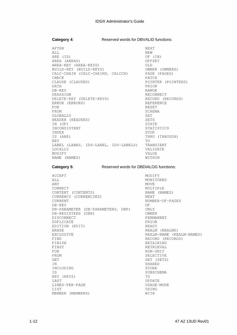
1.5.3 Reserved Words
Reserved words fall into 5 categories as described below.
Category 1 : Reserved words for common commands and for dispatchingto specific command analysis:
ACCEPT NAMEANALYZE (ANALYSE) NOEXECUTE (NOEXEC)BUILD-KEY (BUILD-KEYS) OF (IN)CALC-CHAIN (CALC-CHAINS,CCHAIN) ON (UPON)CHECK ONLYCOMMIT OPTION (OPTIONS)CONNECT PAGE (PAGES)DDLIB1 PATCHDDLIB2 POINTER (POINTERS)DDLIB3 PRINTDELETE-KEY (DELETE-KEYS) RECORD (RECORDS)DISCONNECT QUITDISPLAY READYERASE RECONNECTEVEN RESETEXECUTE (EXEC) ROLLBACKFIND SCHEMAFINISH SIMULOADGET SORTHELP STATUSIN (OF) STOREINDEX SUBSCHEMAIS SYSOUTLABEL (LABELS, IDS-LABEL, IDS-LABELS) TERMINALLIST UPON (ON)LOCK (LOCKS, LOCK-ENTRY, LOCK-ENTRIES) VALIDATEMODIFY WITHMOVE

Introduction
47 A2 13UD Rev01 1-11
Category 2 : Reserved words for DBPRINT functions:
ARE (IS) NUMBERAREA (AREAS) NUMBER-OF-MEMBERSAREA-KEY- (AREA-KEYS) OF (IN)CALC-KEY (CALC) OWNER (OWNERS)FROM PAGE (PAGES)HEADER (HEADERS) POINTERSHEXADECIMAL (HEXA) PRINTIN (OF) RANGEINDEX RECORDS (RECORDS)IS (ARE) SYSTEMLABEL (LABELS, IDS-LABEL, IDS-LABELS) THRU (THROUGH)MAXIMUM WHENMEMBERS WITHMINIMUM WITHINNAME (NAMES)
Category 3 : Reserved words for DBANALYS functions:
AFTER NCRVNIOANALYSE (ANALYZE) NKEYVNIOARE (IS) NKEYVTYPEAREA NPGVNKEYBYTES NPGVNRCCALC NPGVUSPCALC-INTERVAL NPCVTYPECLUSTERED NUMBERDMCL NUMBER-OF-PAGESFROM OF (IN)GENERATE OWNERGRAPH OWNERSIN (OF) OWNER-MEMBER (OWNERS-MEMBERS)INCREMENT PAGE (PAGES)INDEX PAGE-SIZEINTERVAL RANGEIS (ARE) READI-O RECORDKEY (KEYS) REDEFINEKEYVCC REPORTLINES-PER-PAGE SIMULOADLOAD-MODE SKIPPINGLOCATION SORTMEMBER (MEMBERS) THRESHOLDNAME THRU (THROUGH)NCCVNCR WITHNCLVNPG WITHINNCLVNPG
IDS/II Administrator's Guide
1-12 47 A2 13UD Rev01
Category 4 : Reserved words for DBVALID functions:
AFTER NEXTALL NEWARE (IS) OF (IN)AREA (AREAS) OFFSETAREA-KEY (AREA-KEYS) OLDBUILD-KEY (BUILD-KEYS) OWNER (OWNERS)CALC-CHAIN (CALC-CHAINS, CALCCH) PAGE (PAGES)CHECK PATCHCLAUSE (CLAUSES) POINTER (POINTERS)DATA PRIORDB-KEY RANGEDEASSIGN RECONNECTDELETE-KEY (DELETE-KEYS) RECORD (RECORDS)ERROR (ERRORS) REFERENCEFOR RESETFROM SCHEMAGLOBALLY SETHEADER (HEADERS) SETSIN (OF) STATEINCONSISTENT STATISTICSINDEX STOPIS (ARE) THRU (THROUGH)KEY TOLABEL (LABES, IDS-LABEL, IDS-LABELS) TRANSIENTLOCALLY VALIDATEMODIFY VALUENAME (NAMES) WITHIN
Category 5 : Reserved words for DBDIALOG functions:
ACCEPT MODIFYALL MONITOREDANY MOVECONNECT MULTIPLECONTENT (CONTENTS) NAME (NAMES)CURRENCY (CURRENCIES) NEXTCURRENT NUMBER-OF-PAGESDB-KEY OFDN-PARAMETER (DB-PARAMETERS, DBP) ONLYDB-REGISTERS (DBR) OWNERDISCONNECT PERMANENTDUPLICATE PRIOREDITION (EDIT) READYERASE REALM (REALMS)EXCLUSIVE REALM-NAME (REALM-NAMES)FIND RECORD (RECORDS)FINISH RETAININGFIRST RETRIEVALFOR RUN-UNITFROM SELECTIVEGET SET (SETS)IN SHAREDINCLUDING STOREIS SUBSCHEMAKEY (KEYS) TOLAST UPDATELINES-PER-PAGE USAGE-MODELIST USINGMEMBER (MEMBERS) WITH

Introduction
47 A2 13UD Rev01 1-13
MEMBERSHIP WITHINMINIMUM-DB-KEY WORKING-STORAGE (WORKING-STORAGES)

IDS/II Administrator's Guide
1-14 47 A2 13UD Rev01
1.6 EXECUTION ENVIRONMENT OF THE DATABASE UTILITY
The Database Utility can be run in a batch as well as in an IOF environment. Though thefunctions performed are the same in both environments, there are differences in:
• the way commands are input to the utility;
• the destination, contents and format of the reports produced by the utility;
• the sequencing of commands.
Tables 1-1 and 1-2, further on in this section, list the options available in the IOFenvironment.
Commands may be input in three modes:
1. OPTIONS input mode: the source is the OPTIONS string of the STEP statement.
2. COMFILE input mode: the source is a command file.
3. TERMINAL input mode: the source is the terminal keyboard.
Reports may be produced in three modes:
1. SYSOUT display mode: the main destination is the SYSOUT file.
2. TERMINAL display mode: the main destination is the TERMINAL.
3. TERMINAL AND SYSOUT display mode: the main destination is the TERMINAL (theSYSOUT file is a copy of the TERMINAL report).
The reports produced may be edited in two formats:
• SYSOUT format corresponds to a line of 130 characters.
• TERMINAL format corresponds to a line of 80 characters.
The sequencing of commands may be driven by either:
• a STATUS indicator tested after each command,
• the terminal operator.

Introduction
47 A2 13UD Rev01 1-15
1.6.1 BATCH Operability
See Figure 1-1, upper part.
COMMAND INPUT MODES
The OPTIONS mode and the COMFILE mode are available. These modes are exclusive,the definitive selection being done at the beginning of the step.
DISPLAY MODE
The SYSOUT mode is available. Reports are produced in the SYSOUT format when theSYSOUT line length is greater than or equal to 130. Otherwise, reports are produced inTERMINAL format.
COMMAND SEQUENCING
The sequencing of commands is based upon the STATUS indicator set by the utility at theend of a function, and on the presence or absence of a STATUS command immediatelyfollowing the command just executed.

IDS/II Administrator's Guide
1-16 47 A2 13UD Rev01
BATCH ENVIRONMENT
DATABASEUTILITY
Results
Commands
OPTIONSstrin g COMFILE
TERMINAL
echo IOF echo(LIST)
IOF
IOF ENVIRONMENT
LIBRARYMEMBER
Results
DATABASEUTILITY
Commands
SYSOUT
OPTIONS strin g
COMFILE
$SWI
SYSOUT
Results
Figure 1-1. Command Input and the Display of Results in Batch and IOF Environments.

Introduction
47 A2 13UD Rev01 1-17
1.6.2 IOF Operability
See Figure 1-1, lower part.
COMMAND INPUT MODES
The TERMINAL mode, the OPTIONS mode, and the COMFILE mode are available.These modes are exclusive, the definitive selection being made at the beginning of thestep.
The TERMINAL mode corresponds to fully interactive processing: in this mode, one ormore commands are entered in response to a "C:" prompt.
The OPTIONS/COMFILE modes correspond to semi-interactive processing: in this mode,a sequence of commands is prepared as in batch, prior to the activation of the utility.
The TERMINAL mode, viewed by the utility, may be a mixture of fully interactiveprocessing and semi-interactive processing if the SWITCH INPUT or ALTER INPUTfacility offered by IOF is used. In this case, several switches between fully interactive andsemi-interactive processing may take place during the step. The utility is unaware of thesuch switches ($SWI or $AI operations) and considers the command mode to be theTERMINAL mode during the entire step. This affects resynchronization in case anycommand syntax errors occurred, as explained later in this section.
DISPLAY MODES
The SYSOUT mode, the TERMINAL mode and the TERMINAL AND SYSOUT mode areavailable.
The contents and format of reports directed to the SYSOUT file and/or to the terminal areshown in Tables 1-1 and 1-2 for each of the three display modes.
You can change the display mode during the step. The default display mode at thebeginning of the step is the SYSOUT mode for all environments except the fullyinteractive environment, for which the default display mode is the TERMINAL mode.
COMMAND SEQUENCING
The sequencing of commands is driven by the terminal operator in the TERMINAL inputmode and by the STATUS indicator in the OPTIONS/COMFILE input mode.
NOTE: In the TERMINAL mode, if several commands are entered in response to a "C:"prompt, they are executed in sequence independently of their STATUSindicator. The same occurs for the sequence of commands read from a switchmember.
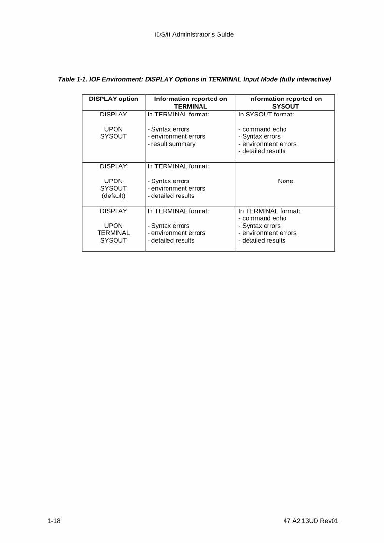
IDS/II Administrator's Guide
1-18 47 A2 13UD Rev01
Table 1-1. IOF Environment: DISPLAY Options in TERMINAL Input Mode (fully interactive)
DISPLAY option Information reported onTERMINAL
Information reported onSYSOUT
DISPLAY
UPONSYSOUT
In TERMINAL format:
- Syntax errors- environment errors- result summary
In SYSOUT format:
- command echo- Syntax errors- environment errors- detailed results
DISPLAY
UPONSYSOUT(default)
In TERMINAL format:
- Syntax errors- environment errors- detailed results
None
DISPLAY
UPONTERMINALSYSOUT
In TERMINAL format:
- Syntax errors- environment errors- detailed results
In TERMINAL format:- command echo- Syntax errors- environment errors- detailed results
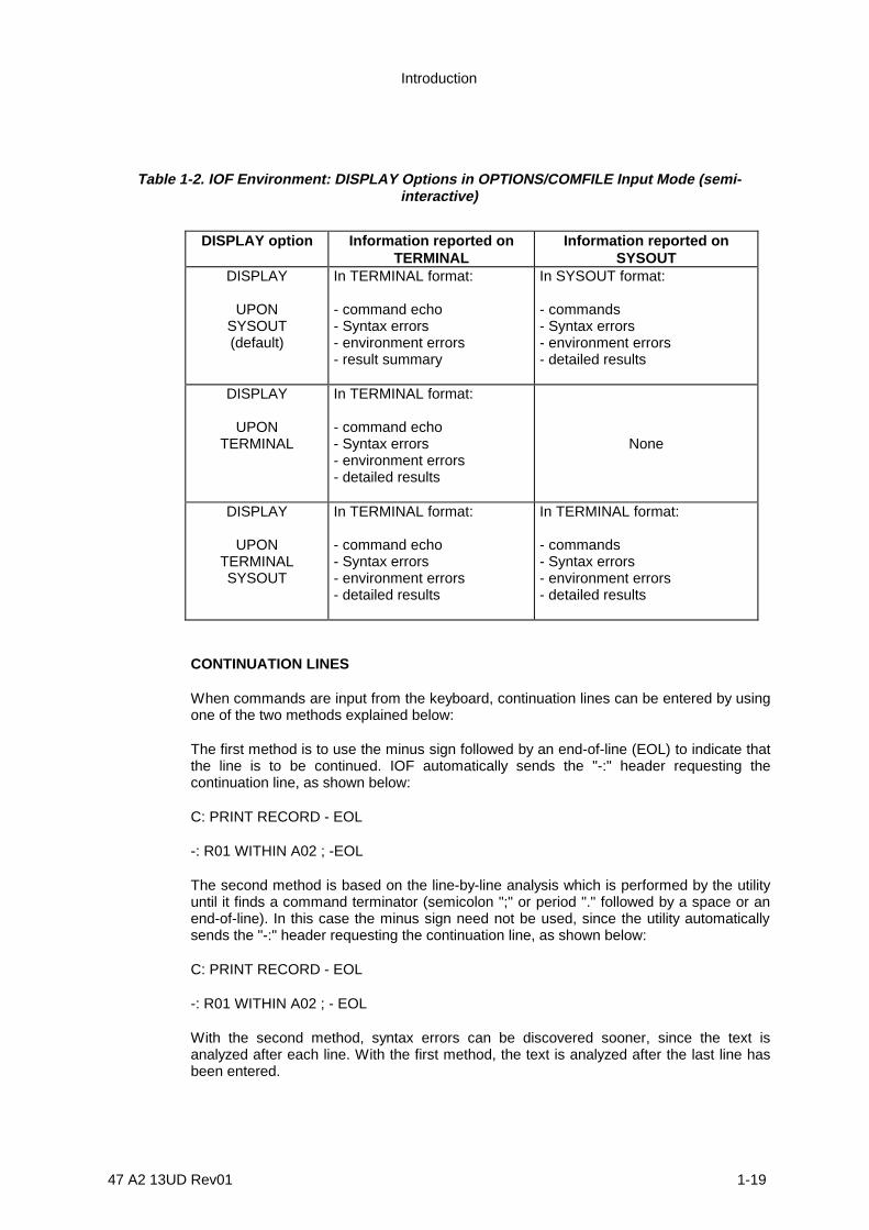
Introduction
47 A2 13UD Rev01 1-19
Table 1-2. IOF Environment: DISPLAY Options in OPTIONS/COMFILE Input Mode (semi-interactive)
DISPLAY option Information reported onTERMINAL
Information reported onSYSOUT
DISPLAY
UPONSYSOUT(default)
In TERMINAL format:
- command echo- Syntax errors- environment errors- result summary
In SYSOUT format:
- commands- Syntax errors- environment errors- detailed results
DISPLAY
UPONTERMINAL
In TERMINAL format:
- command echo- Syntax errors- environment errors- detailed results
None
DISPLAY
UPONTERMINALSYSOUT
In TERMINAL format:
- command echo- Syntax errors- environment errors- detailed results
In TERMINAL format:
- commands- Syntax errors- environment errors- detailed results
CONTINUATION LINES
When commands are input from the keyboard, continuation lines can be entered by usingone of the two methods explained below:
The first method is to use the minus sign followed by an end-of-line (EOL) to indicate thatthe line is to be continued. IOF automatically sends the "-:" header requesting thecontinuation line, as shown below:
C: PRINT RECORD - EOL
-: R01 WITHIN A02 ; -EOL
The second method is based on the line-by-line analysis which is performed by the utilityuntil it finds a command terminator (semicolon ";" or period "." followed by a space or anend-of-line). In this case the minus sign need not be used, since the utility automaticallysends the "-:" header requesting the continuation line, as shown below:
C: PRINT RECORD - EOL
-: R01 WITHIN A02 ; - EOL
With the second method, syntax errors can be discovered sooner, since the text isanalyzed after each line. With the first method, the text is analyzed after the last line hasbeen entered.

IDS/II Administrator's Guide
1-20 47 A2 13UD Rev01
NOTE: A combination of the two methods is possible for the same command.
RESYNCHRONIZATION AFTER SYNTAX ERRORS
If commands are not syntactically correct, the utility returns to the command level.
In TERMINAL mode, the utility discards an erroneous command and, if applicable, alsodiscards subsequent commands which were already entered in response to the same "C:"prompt.
In OPTIONS/COMFILE mode, the utility skips the erroneous command until it finds thecommand terminator and resynchronizes to the next command.
When TERMINAL mode corresponds to the $SWI or $AI Facility, the utility resynchronizesto the next "record" of the switch member. It is therefore recommended, when storingcommands in a switch member from an input enclosure, to use the CONTCHAR option inorder to obtain one "record" per command. Otherwise, if an error is detected in the firstrecord of a multi-record command, the utility will resynchronize to the second record. Inthis case, since the utility expects a command keyword as the first word of this record, itwill diagnose a new error and the processing will be repeated until all the records of thecommand have been read.
BREAK FACILITY
The break facility is available in TERMINAL, OPTIONS and COMFILE modes.
If the answer to the " ??? " prompt is RESUME, QUIT, RETURN or ESCAPE, standardprocessing is resumed.
If the answer to the prompt message " ??? " is "IT" or "/", the utility terminates theprocessing of the current command as soon as possible and returns to the commandlevel. Certain situations are described below:
• When the utility is analyzing a command or printing results, the termination is virtuallyimmediate.
• When the utility is executing other phases of processing, the termination may bedeferred. For example, a SORT phase cannot be interrupted. If the termination isabsolutely required, the QUIT option must be selected, causing a return to systemlevel.

Introduction
47 A2 13UD Rev01 1-21
1.7 CONCURRENT ACCESS IN THE DATABASE UTILITY
1.7.1 Usage Modes for Areas and Indexes
The Database Utility follows the same rules as the user steps in terms of concurrentaccess control in BATCH or IOF environment.
For each type of command, the areas and indexes involved are readied in the usage-mode that allows maximum concurrent access while providing the level of consistencynecessary to the logic of command. For example, when DBPRINT prints the records of anarea range or the label of an index file, it readies the area or the index file in MONITOREDRETRIEVAL.
In the same way, when DBVALID has to patch an area page or an index label, it readiesthe area or the index file in MONITORED UPDATE, thus permitting on-line patching of alocally corrupted database. However, when DBVALID has to validate all the set pointers ofthe database, it readies the areas in SHARED RETRIEVAL, allowing concurrent readersbut forbidding updates. When BUILD-KEY or DELETE-KEY are used to build or deletekeys from index file, they ready the index file in EXCLUSIVE UPDATE mode.
As with user steps, the sharing mode specified by the utility in READY statements may berendered more exclusive by the usage-mode specified in the JCL ASSIGN/DEFINEstatements. The overriding rules are illustrated in Figure 6-3 of the Full IDS/II ReferenceManual Volume II.
1.7.2 Commitment-points
When the Database Utility runs in MONITORED mode, commitment-units are required.
The COMMIT function is explicitly activated by using the COMMIT command. This allowsa sequence of commands (PRINT PAGE, PATCH PAGE, VALIDATE PAGE, BUILD-KEY,DELETE-KEY) to be executed in the same commitment-unit. For example, if the results ofa validation following a patch session are satisfactory, the user confirms the modificationsby activating the COMMIT command. If the results are not satisfactory, the user discardsthe modifications by activating the ROLLBACK command, which returns the database tothe state it was in at the beginning of the commitment-unit.
Implicit COMMIT functions are also performed by the utility:
1) at the initial opening of a monitored area or index file, either implicitly through thePRINT, VALIDATE, ANALYZE, RECONNECT, PATCH, BUILD-KEY or DELETE-KEY commands, or explicitly through the READY command;
2) at the execution of each SCHEMA command, if a least one COMMIT has alreadybeen issued.

IDS/II Administrator's Guide
1-22 47 A2 13UD Rev01
When the MONITORED mode of all the database files involved in a command isoverridden at the JCL level, thus rendering General Access Control (GAC) inactive, theCOMMIT functions become a checkpoint. Such a checkpoint is only effective if theREPEAT option is specified in the STEP statement. The ROLLBACK function returns thedatabase to the state it was in at the last check-point or at the beginning of the step.

47 A2 13UD Rev01 2-1
2. Performance and Evolution of the Database
This section describes the performance of the database in terms of:
• database structure;• concurrent access;• journals;• buffers strategy;• run-time monitoring options;• initial database loading.
IDS/II Administrator's Guide
2-2 47 A2 13UD Rev01
2.1 STRUCTURE OF A DATABASE
The structure of a database is largely determined by the applications for which it will beused.
2.1.1 Compromise Between Applications
As a model of a real situation, the structure of the database is assumed to incorporate allthe entities and relationships necessary for all the required applications.
This structure may also include additional entities and relationships whose sole purpose isto facilitate access to the main entities in a transactional or batch environment. Becausethe access optimization in one environment often causes an overhead in another, it is upthe DBA to decide which applications will have priority in terms of frequency, responsetime, etc., and to define the data structure accordingly.
ACCESS BASED ON KEY VALUES
The entity most frequently used for facilitating access to records is the key value. The keythat is best suited to the transactional environment is the CALC-key , because, undernormal operating conditions, access to a CALC record requires only one I/O operation.
If a record contains secondary keys , the following methods exist to access that record:
1) direct access within the database using the secondary key (unique key or firstduplicate),
2) sequential access within an index file using one of the following relative positions:
- position relative to the value of the key (FIRST, LAST, positive or negativeordinal),
- a position relative to the current-of-key (NEXT, PRIOR),
3) sequential access using a given key.
SEQUENTIAL ACCESS TO CALC RECORDS
In batch applications, the sorted order of CALC entry-point records is not important. Thereis, however, a need for optimizing the frequent modification of a large number of theseCALC records. If these records are accessed randomly, the disk heads must moveconstantly. Therefore, it may improve performance to implement the technique similar tothe one described later in this section for the initial loading of CALC records. Thistechnique consists of sorting the records according to the order of the bucket pagenumber of the CALC records to which they correspond (the page number is obtainedthrough the H_DML_UCHASH procedure). Once sorted, these records drive themodification program in such a way that the apparently random access to CALC recordscauses the disk heads to move sequentially through the database.
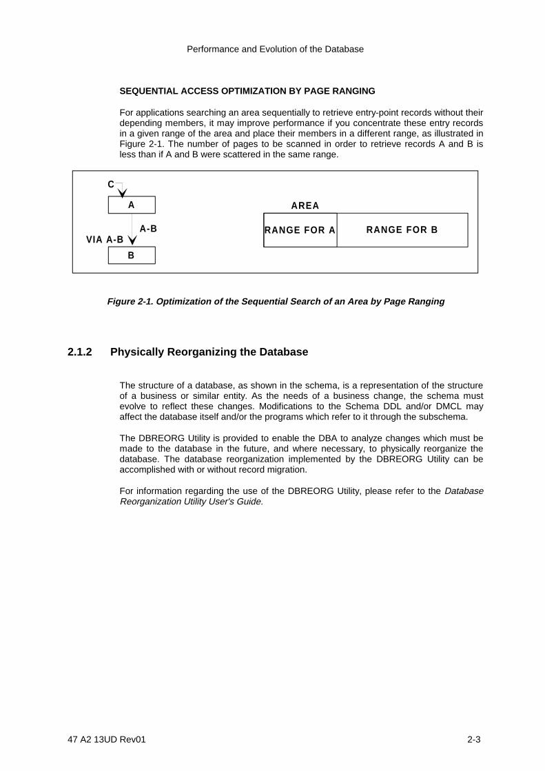
Performance and Evolution of the Database
47 A2 13UD Rev01 2-3
SEQUENTIAL ACCESS OPTIMIZATION BY PAGE RANGING
For applications searching an area sequentially to retrieve entry-point records without theirdepending members, it may improve performance if you concentrate these entry recordsin a given range of the area and place their members in a different range, as illustrated inFigure 2-1. The number of pages to be scanned in order to retrieve records A and B isless than if A and B were scattered in the same range.
C
A
B
A-BVIA A-B
AREA
RANGE FOR A RANGE FOR B
Figure 2-1. Optimization of the Sequential Search of an Area by Page Ranging
2.1.2 Physically Reorganizing the Database
The structure of a database, as shown in the schema, is a representation of the structureof a business or similar entity. As the needs of a business change, the schema mustevolve to reflect these changes. Modifications to the Schema DDL and/or DMCL mayaffect the database itself and/or the programs which refer to it through the subschema.
The DBREORG Utility is provided to enable the DBA to analyze changes which must bemade to the database in the future, and where necessary, to physically reorganize thedatabase. The database reorganization implemented by the DBREORG Utility can beaccomplished with or without record migration.
For information regarding the use of the DBREORG Utility, please refer to the DatabaseReorganization Utility User's Guide.

IDS/II Administrator's Guide
2-4 47 A2 13UD Rev01
2.2 CONCURRENT ACCESS
The two access modes described below must be considered when working with area andindex files.
2.2.1 SHARED RETRIEVAL Usage Mode
When the database is shared at the file level in SHARED RETRIEVAL mode, theoverhead in processor time which is created while operating in EXCLUSIVE mode doesnot occur. With the SHARED RETRIEVAL mode however, an elapsed-time overhead canoccur due to the serialization of concurrent reader accesses to the same database disks.This type of overhead occurs at the physical I/O level.
2.2.2 MONITORED Usage Mode
When the database is shared at the file level in MONITORED mode, the following types ofoverhead can occur:
• processor-time overhead due to the dynamic page reservation,
• elapsed-time overhead due to the serialization of concurrent accesses to differentpages of the same database disks; this overhead takes place at the physical I/O level.
• possible elapsed-time overhead due to conflicts for the same pages. This overhead cantake the form of a simple wait or, in case of deadlock, of a return to the lastcommitment-point followed by a restart of the consistency-unit.
2.2.3 TDS Environment
In the TDS environment, the database is always accessed in MONITORED mode. Theresponse time of transactions depends on many factors. The following paragraphsdiscuss only the effects of conflicts on database pages. There is no discussion here of thenumber of database accesses, of the availability of buffers, or of other resources.
If two separate transactions work on different pages of the database, there is noperceptible interaction between them.
If two separate transactions attempt to update the same pages or to read the same pagesin EXCLUSIVE RETRIEVAL mode (this is the default option in TDS generation), a wait ordeadlock occurs. The response time of the transaction which is thus placed in the waitstate or aborted is affected by the reaction time of the operator performing the competingtransaction. Under TDS, the terminal operator corresponding to the suspendedtransaction is informed of the situation by this message: WAITING FOR RESOURCE.

Performance and Evolution of the Database
47 A2 13UD Rev01 2-5
If two separate transactions attempt to read the same pages in SHARED RETRIEVALmode (the SHARED option in TDS generation), they proceed without any effect onresponse time. This mode is recommended when transactions must follow a commonpath in the database, for example, when consulting records acting as a directory.
A transaction may also run in STATISTICAL RETRIEVAL mode (the SUPPRESSCONCURRENT CONTROL option in TDS generation). Since in this mode the pagereservation is disabled, there is no wait or deadlock caused by other transactions. Thereis, however, a risk of apparent database inconsistency. If such an inconsistency occurs,the transaction is given one more chance to run, that is, it is aborted and restarted inEXCLUSIVE RETRIEVAL mode. If the inconsistency occurs a second time, it is a realinconsistency, and at that point, the transaction is definitively aborted.
2.2.4 IOF Environment
Most of the information in the above paragraph on the TDS environment remains true forIOF commitment-units accessing a database concurrently in MONITORED mode. Thedifference is that, in the case of a page conflict, the response time can be greater underIOF than under TDS. TDS transactions are designed in such a way that the elapsed-timedue to database accesses is negligible compared to the amount of exchanges takingplace over the telecommunications lines. For IOF steps (such as the Database Utility), thenumber of database accesses performed during a commitment-unit may become toonumerous, increasing both the probability of page conflicts and the response time ofsuspended concurrent commitment-units.
In the IOF environment, users are not warned of all wait states and deadlocks. Aninteractive user of the Database Utility may be given no warning about the wait state of hiscommitment-unit, but only a warning concerning a restart after deadlock. In this case, heshould define commitment-units, performing as few database accesses as possible, andthen respond, as quickly as possible, to the "C:" prompts which are enclosed in hiscommitment-units.
2.2.5 BATCH Environment
For BATCH steps concurrently accessing a database in MONITORED mode, responsetime is not an important factor. On the other hand, commitment-units may be long, but therisk of page conflicts increases with the number of database accesses performed by thecommitment-units.
2.2.6 All Environments
When TDS, IOF, and BATCH steps access the same database concurrently inMONITORED mode, the TDS response time has priority. This rule imposes therequirement that the commitment-units of the IOF and BATCH retrieval steps be run inSTATISTICAL RETRIEVAL mode whenever the structure searched is stable. In case of

IDS/II Administrator's Guide
2-6 47 A2 13UD Rev01
apparent or real database inconsistency, however, these commitment-units are not givena second chance as in TDS. They are permanently aborted.

Performance and Evolution of the Database
47 A2 13UD Rev01 2-7
2.3 JOURNALS
Journals are used to ensure the integrity of database files. They allow the system torestore the database to a consistent state when a step or transaction aborts, when thesystem crashes, or if the database disk is physically damaged. See Section 3 of thismanual for further details. Protection with journals has an impact on secondary storage,processor-time, and elapsed-time.
2.3.1 BEFORE Journal
The BEFORE Journal records images of entire pages of the database before amodification is implemented.
The space reserved on the system disk for BEFORE Journal protection must be globallyadapted to an average number of simultaneous consistency-units which record anaverage number of BEFORE images of an average page-size. When a consistency-unitterminates, its BEFORE Journal space is released and becomes available for asubsequent consistency-unit.
When a page is read into a buffer, the page cannot be modified in the buffer until thecorresponding BEFORE image is written on disk. This absence of buffering of BEFOREimages entails an increase in elapsed-time.
If a page is mofidied several times without the buffer being rewritten to disk in the interim,only one BEFORE image is recorded. If a modified page is written back to disk and thenreread into a buffer for another modification, another BEFORE image is recorded at thatpoint. The most disadvantageous performance occurs when the random distribution ofpage modifications causes the buffer management memory mechanism to becomeinoperative. If this happens, one I/O is necessary on the BEFORE Journal for every pagemodification.
2.3.2 AFTER Journal
The AFTER Journal records images of the portions of a page that have been modified. AnAFTER image of the entire page is only needed when an area page reorganization isrequired because of the physical deletion of inactive records.
AFTER Journal files reside on disk or tape. They require more space than BEFOREJournal files because AFTER images must be kept after the end of each consistency-unit.The DBA can define a re-use cycle for AFTER Journal files by using the AFTER Journalutility JAGEN.
As opposed to BEFORE images, AFTER images are buffered. These are written ontodisk only when their buffers are full or at the end of the consistency-unit. Thus, thenumber of I/O on the AFTER Journal does not significantly increase elapsed time.

IDS/II Administrator's Guide
2-8 47 A2 13UD Rev01
2.4 BUFFER STRATEGY
2.4.1 Run-time Parameters
UFAS Buffer Management is designed to optimize the processing of clusters by theDBCS. In other words, it manages operations taking place on the same database pagesduring a certain time.
The mechanism involved is the memory feature. This feature keeps track of pages whichare contained in the buffers and also defers their rewriting to disk if modifications havebeen made. Therefore, if the DBCS handles a number of pages which is less than thenumber of buffers available, all these operations are actually transfers within mainmemory between the UWA and the buffers.
When it becomes necessary to read a new page into the buffers which is not alreadypresent there, the Least Recently Used (LRU) algorithm is applied to select which buffer isto be emptied. This selection is made regardless of the "read" or "modified" status of thisbuffer.
With this mechanism of UFAS Buffer Management at his/her disposal, the DBA can acton two run-time parameters to tune the performance of DML programs: the number ofbuffers (NUMBUF) and the pool option. The pool option parameter allows the sharing ofthe same buffer space by the various areas and index files of the same consistency-unitand, in certain circumstances, it allows the sharing of the same buffer space by severalconcurrent consistency-units.
The following paragraphs discuss buffer management in the context of the variousoperating environments.
2.4.2 BATCH/IOF Mono-Step Case
The Mono-Step case corresponds to a step accessing the database in non-concurrentenvironment. Buffers are created in type-2 segments. These are segments which residein the address space reserved for the process-group (see Figure 2-2).
If no pool exists, each area or index is allocated NUMBUF buffers. The buffer space foreach area or index is established relative to its page size.
The memory feature and replacement algorithm of UFAS Buffer Management areeffective for each area or index independently of the others. Consequently, the NUMBUFparameter should be set according to the area which contains the largest clusters.
If a pool of NUMBUF buffers has been created, the buffer space can contain pages of anyarea or index and is dynamically adapted to the different page sizes. With such a pool, themain memory requirements are significantly less than if no pool exists.
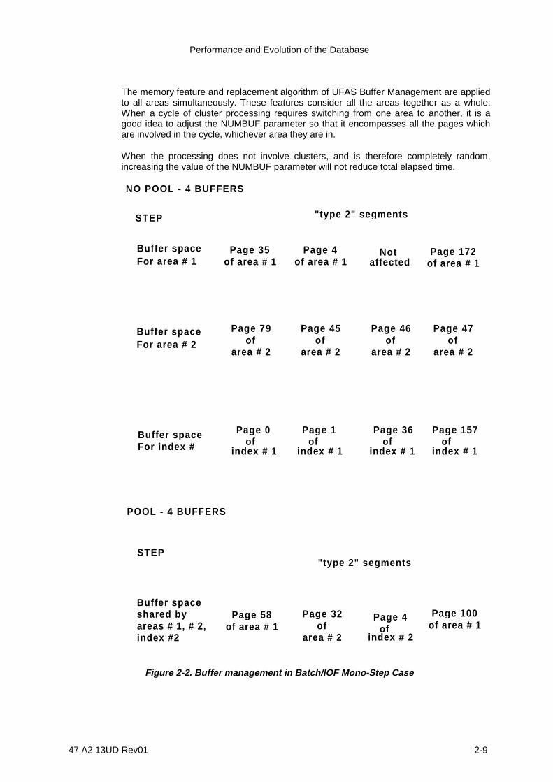
Performance and Evolution of the Database
47 A2 13UD Rev01 2-9
The memory feature and replacement algorithm of UFAS Buffer Management are appliedto all areas simultaneously. These features consider all the areas together as a whole.When a cycle of cluster processing requires switching from one area to another, it is agood idea to adjust the NUMBUF parameter so that it encompasses all the pages whichare involved in the cycle, whichever area they are in.
When the processing does not involve clusters, and is therefore completely random,increasing the value of the NUMBUF parameter will not reduce total elapsed time.
NO POOL - 4 BUFFERS
Page 35of area # 1
Buffer spaceFor area # 1
Buffer spaceFor area # 2
Page 4of area # 1
Page 172of area # 1
"type 2" se gments
Page 79of
area # 2
Page 45of
area # 2
Page 46of
area # 2
Page 47of
area # 2
POOL - 4 BUFFERS
Page 58of area # 1
Page 32of
area # 2
Page 100of area # 1
STEP
STEP"type 2" se gments
Notaffected
Page 4 of
index # 2
Buffer spaceFor index #
Page 1 of
Page 36 of
Page 157 of
index # 1
Page 0 of
index # 1 index # 1 index # 1
Buffer spaceshared byareas # 1, # 2,index #2
Figure 2-2. Buffer management in Batch/IOF Mono-Step Case

IDS/II Administrator's Guide
2-10 47 A2 13UD Rev01
2.4.3 BATCH/IOF Multi-Step Case
The Multi-Step case corresponds to BATCH/IOF steps which concurently access thedatabase (see Figure 2-3).
In terms of the buffer space, each step is considered separately and treated as in themono-step case. The buffers are also created in type-2 segments for each step. Thismeans that there is no sharing of buffer space between steps. The NUMBUF value andpool option may have different values between steps.
The lock-lists and buffer control table are located in type-0 segments. Type-0 segmentsreside in the address space of all process-groups. The buffer control table is themechanism which allows UFAS to synchronize copies of the same page in the buffers ofdifferent steps.
STEP 2
"t yp e 2" se gments"t yp e 2" se gments
STEP 1
"t yp e 0" se gments
Buffer s pace Buffer s pace(pool or not ) (pool or not )
-Lock_-lists-Buffer control table
Figure 2-3. Buffer Management in Batch/IOF Multi-Step Case

Performance and Evolution of the Database
47 A2 13UD Rev01 2-11
2.4.4 TDS Case (See Figure 2-4)
In a TDS step, the buffer pool is mandatory and applies to the database as well as otherfiles. These buffers are created in type 2 segments and their number is assigned at TDSgeneration (see Figure 2-4).
The transaction within the TDS step has the same function as concurrent BATCH/IOFsteps have within GCOS. There is one difference: in TDS, the buffer pool allows a doublerather than a single optimization of the main memory requirements. The doubleoptimization consists of the following:
1) The buffer pool shares the buffer space among all areas and index files of thetransaction (as in the mono-step case),
2) The buffer pool also shares the buffer space among all transactions (unlike the multi-step case). In addition, there is only one copy in the buffers of a page accessed inSHARED RETRIEVAL mode by concurrent transactions.
The second optimization may be used if an elapsed-time overhead occurs whenconcurrent transactions compete for buffers. In this case, since each transaction canretain up to the value of NUMBUF buffers in memory, the presence of concurrenttransactions will usually reduce this number and cause more frequent page transfers.
However the NUMBUF value cannot be reduced lower than a minimum value whichdepends on the recovery method associated with the transaction. This is described below.
If the transaction runs with BEFORE Journal protection, the number of buffers held by theDBCS at a given time is at most four. These buffers are released during the exchanges ofthe transaction commitment-units. If all the transactions run with a BEFORE journal, theminimum value of the NUMBUF parameter is three times the number of simultaneoustransactions.
If the transaction runs with an AFTER Journal and with DEFERRED UPDATESprotection, the number of buffers held by the DCBS is at most four plus the number ofbuffers containing modified pages. These modified pages cannot be rewritten to disk untilthe commitment-point. The buffers are not released during exchanges of the transactioncommitment-units. If all the transactions run with this mode of recovery, the NUMBUFvalue must be roughly equal to the average number of pages modified by a transactionmultiplied by the average number of concurrent transactions.
In light of this limited number of buffers, if the alloted buffers become saturated during atransaction such as the one described in the paragrpah above (return code BUFNBOV),the transaction is aborted. If the BEFORE Journal is implemented, the transaction is givena second chance and is restarted once with BEFORE Journal protection. In conclusion,the DEFERRED UPDATES mechanism should only be used for transactions whichmodify a small amount of pages.
These considerations also apply to concurrent transactions within the TDS step. If thestep is considered as a whole compared to separate BATCH/IOF steps whichconcurrently access the database, we see that it operates as any other step in the multi-step case.
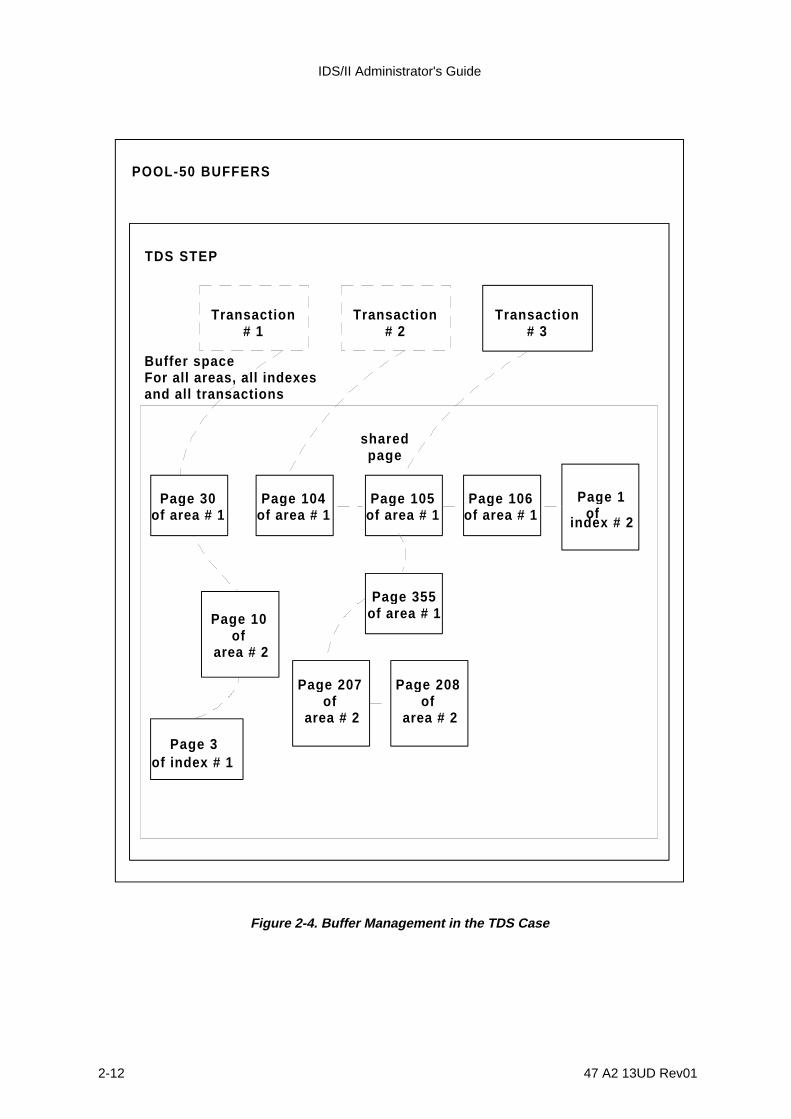
IDS/II Administrator's Guide
2-12 47 A2 13UD Rev01
Transaction# 1
Transaction# 2
Transaction# 3
TDS STEP
POOL-50 BUFFERS
sharedpa g e
Pag e 30of area # 1
Pag e 104of area # 1
Pag e 105of area # 1
Pag e 106of area # 1
Pag e 355of area # 1Pag e 10
of area # 2
Pag e 207of
area # 2
Pag e 208of
area # 2
Page 3of index # 1
Page 1 of
index # 2
Buffer spaceFor all areas, all indexesand all transactions
Figure 2-4. Buffer Management in the TDS Case
Performance and Evolution of the Database
47 A2 13UD Rev01 2-13
2.5 RUN-TIME MONITORING OPTIONS
The processor-time and elapsed-time of DML programs is affected by the selection ofcertain run-time monitoring commands. These are described below:
1) The STATISTICS WITH TIMING option causes an overhead of approximately 5 % ofthe DCBS processor time.
2) The TRACE option influences the DCBS processor-time as well as its elapsed-time,in accordance with the amount of information printed on the IDSTRACE file.
3) The CHECK PAGE STRUCTURE option can increase the DCBS processor-timesignificantly. It should be used only for debugging purposes.
IDS/II Administrator's Guide
2-14 47 A2 13UD Rev01
2.6 INITIAL DATABASE LOADING
2.6.1 Mass Loading of Permanent Records
Two classes of records exist in the database:
• those which are practically permanent,
• those which have a short stay in the database.
Most of the permanent-type records are stored in the database during the initial loadingphase. Since these records are usually built from information recorded in various formatsin several existing files, a general intial loading utility does not exist. Instead, the usermust perform the following operations to load records into the database:
1) write specific COBOL/DML programs to extract information from his/her former files,
2) build the records according to the schema formats,
3) then store these records in the database.
Due to the large number of permanent records to be stored, attention must be paid to theefficiency of the initial loading programs. The following paragraphs discuss certaintechniques which can accelerate the loading operation under certain conditions. Furtheron in this manual, the use of the the DBREORG Utility for initial loading of a new databaseis explained.
2.6.2 Loading of CALC Records that are not AUTOMATIC Members of anySet
These records are main entry points in the database. If they are stored chronologically inan undefined order, the randomization mechanism causes the disk heads to moveconstantly to get a new page for each record.
In order to speed up loading, the CALC records of an area should first be sorted indescending order of the page numbers to which they randomize. This can be done byeither using the SORT Utility in conjunction with the H_DML_UCHASH procedure, or byusing the SORT command of the DBUTILITY. In this way, the disk heads movesequentially through the area.
The sorting order is by descending order of page number because of the placementalgorithm. In this sorting process, synonyms overflow to the next buckets of a higher pagenumber. When records are loaded chronologically in ascending order by page number,the records which overflow to the next buckets may disturb further loading of the recordsthat would randomize to these buckets. This can cause additional overflows (see Figure2-5).
Performance and Evolution of the Database
47 A2 13UD Rev01 2-15
Loading by descending order of page number may lengthen CALC chains which overflow,but it does not penalize CALC chains that do not overflow.
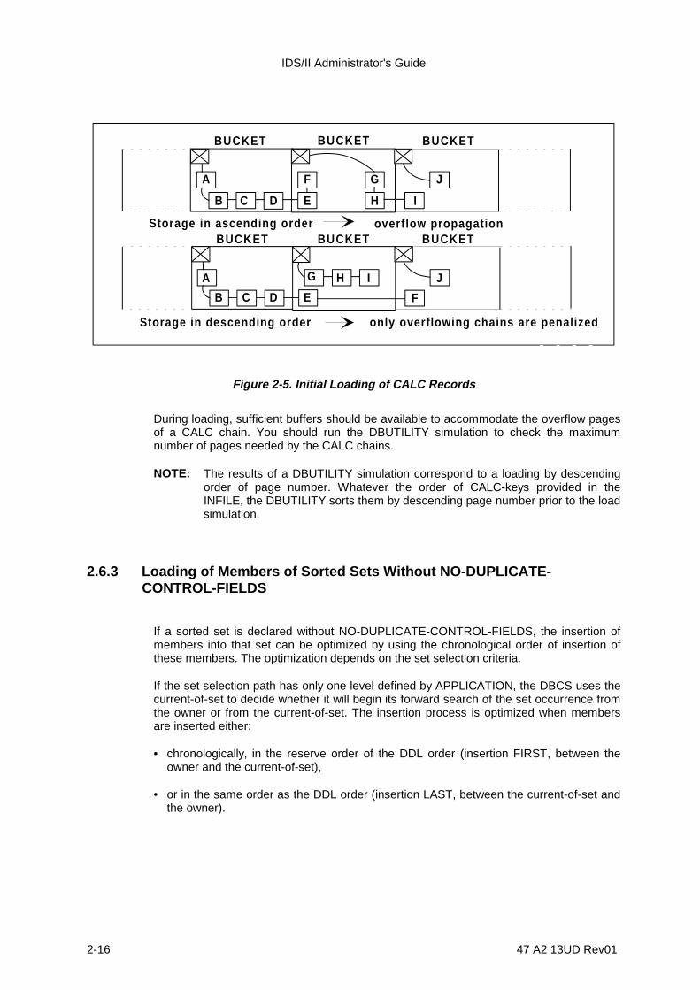
IDS/II Administrator's Guide
2-16 47 A2 13UD Rev01
BUCKET
A
B C D E
F G
H I
J
BUCKET BUCKET
BUCKET
A
B C D E
J
BUCKET BUCKETStorage in ascending order overf low propagation
G H I
Storage in descending order only overflowing chains are penalized
F
Figure 2-5. Initial Loading of CALC Records
During loading, sufficient buffers should be available to accommodate the overflow pagesof a CALC chain. You should run the DBUTILITY simulation to check the maximumnumber of pages needed by the CALC chains.
NOTE: The results of a DBUTILITY simulation correspond to a loading by descendingorder of page number. Whatever the order of CALC-keys provided in theINFILE, the DBUTILITY sorts them by descending page number prior to the loadsimulation.
2.6.3 Loading of Members of Sorted Sets Without NO-DUPLICATE-CONTROL-FIELDS
If a sorted set is declared without NO-DUPLICATE-CONTROL-FIELDS, the insertion ofmembers into that set can be optimized by using the chronological order of insertion ofthese members. The optimization depends on the set selection criteria.
If the set selection path has only one level defined by APPLICATION, the DBCS uses thecurrent-of-set to decide whether it will begin its forward search of the set occurrence fromthe owner or from the current-of-set. The insertion process is optimized when membersare inserted either:
• chronologically, in the reserve order of the DDL order (insertion FIRST, between theowner and the current-of-set),
• or in the same order as the DDL order (insertion LAST, between the current-of-set andthe owner).

Performance and Evolution of the Database
47 A2 13UD Rev01 2-17
If the set selection path is not defined by APPLICATION, the DCBS searches the setoccurrence in the forward direction starting from the owner. In this case, the insertionprocess is only optimized when members are chronologically inserted in the reverse orderof the DDL order (insertion FIRST). The least efficient method of insertion in this case is achronological order of insertion equal to the DDL order (insertion LAST after a search ofthe entire occurrence). This method should be used only when the set occurrences areshort and clustered, and when there are enough buffers to accommodate the clusters.
If NO-DUPLICATE-CONTROL-FIELDS is defined for the set, no optimization is possiblesince the entire set occurrence must be searched for NO DUPLICATES checks.
2.6.4 Building of Secondary Keys
Updating the index file can be deferred with regard to the initial loading of database areas.To do this, the index must be declared detached in the Schema DMCL by using the NOON-LINE UPDATE MANDATORY Clause. Then the index must actually be detached atrun-time. This is done by invoking the NO ON-LINE UPDATE MANDATORY Clause ofIDSOPT. Once these two clauses are invoked, keys are created by using the BUILD-KEYcommand. This operation accelerates the loading of areas.
The rebuilding of keys with the BUILD-KEY command induces a sequential and completescan of the area. The keys are then built according to the order of the db-keys. This cancause an overhead in accessing the index page because key values are not consecutive.
If the loaded records are sorted according to the value of the secondary key, it is moreefficient to update the index on-line. This causes fewer I/O's to the area and the index.
2.6.5 Use of a Temporary Loading Schema
The schema which defines the database, which is used by production programs, isdesigned to optimize the processing of the programs themselves or to enforce structuralcontraints. You may define your own temporary loading schema, which would be betteradapted to the loading algorithms.
We will call a schema which defines the database for daily operations the productionschema , as opposed to a temporary loading schema. The differences between such aloading schema and the production schema are the following:
• the set selection criteria,• the set ordering criteria,• and the set membership.
Examples of the differences between these two types of schemas are given in thefollowing paragraphs. The DML programs which perform the initial loading must becompiled against the loading schema. This loading schema must be stamped with thesame DMCL reference date as the production schema since the areas and index files arepreallocated using the production schema.
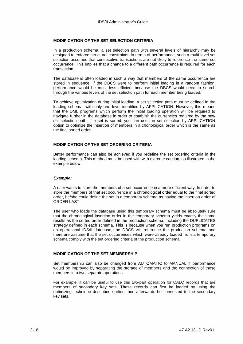
IDS/II Administrator's Guide
2-18 47 A2 13UD Rev01
MODIFICATION OF THE SET SELECTION CRITERIA
In a production schema, a set selection path with several levels of hierarchy may bedesigned to enforce structural constraints. In terms of performance, such a multi-level setselection assumes that consecutive transactions are not likely to reference the same setoccurrence. This implies that a change to a different path occurrence is required for eachtransaction.
The database is often loaded in such a way that members of the same occurrence arestored in sequence. If the DBCS were to perform initial loading in a random fashion,performance would be must less efficient because the DBCS would need to searchthrough the various levels of the set selection path for each member being loaded.
To achieve optimization during initial loading, a set selection path must be defined in theloading schema, with only one level identified by APPLICATION. However, this meansthat the DML programs which perform the initial loading operation will be required tonavigate further in the database in order to establish the currencies required by the newset selection path. If a set is sorted, you can use the set selection by APPLICATIONoption to optimize the insertion of members in a chonological order which is the same asthe final sorted order.
MODIFICATION OF THE SET ORDERING CRITERIA
Better performance can also be achieved if you redefine the set ordering criteria in theloading schema. This method must be used with with extreme caution, as illustrated in theexample below.
Example:
A user wants to store the members of a set occurrence in a more efficient way. In order tostore the members of that set occurrence in a chronological order equal to the final sortedorder, he/she could define the set in a temporary schema as having the insertion order ofORDER LAST.
The user who loads the database using this temporary schema must be absolutely surethat the chronological insertion order in the temporary schema yields exactly the sameresults as the sorted order defined in the production schema, including the DUPLICATESstrategy defined in each schema. This is because when you run production programs onan operational IDS/II database, the DBCS will reference the production schema andtherefore assume that the set occurrences which were already loaded from a temporaryschema comply with the set ordering criteria of the production schema.
MODIFICATION OF THE SET MEMBERSHIP
Set membership can also be changed from AUTOMATIC to MANUAL if performancewould be improved by separating the storage of members and the connection of thosemembers into two separate operations.
For example, it can be useful to use this two-part operation for CALC records that aremembers of secondary key sets. These records can first be loaded by using theoptimizing technique described earlier, then afterwards be connected to the secondarykey sets.

Performance and Evolution of the Database
47 A2 13UD Rev01 2-19
CHANGING THE STATUS OF A DETACHED INDEX
It is useful to change the status of an index from detached to attached in order to deferthe building of keys. When the index is attached, the overhead caused by coherencechecks is avoided. In the DML program, the FIND WITHIN KEY Clause cannot be used ifthe index is attached.

IDS/II Administrator's Guide
2-20 47 A2 13UD Rev01

47 A2 13UD Rev01 3-1
3. Database Integrity
3.1 THREATS TO DATABASE INTEGRITY
A database contains information vital to an organization. Therefore, the databaseadministrator must be constantly concerned with preserving the integrity of the database.Examples of circumstances in which this integrity is endangered are listed below.
1) If the system crashes or if a step aborts when the data has been opened in updatemode without BEFORE Journal protection having been activated, the database is leftin an inconsistent state for the following reasons:
UFAS buffers containing modified pages are not written back to the disk if thesystem crashes or if a step aborts while a UFAS primitive is active. If, on the otherhand, a step aborts outside a UFAS primitive, the buffers are rewritten.
Whether the buffers are written back to disk or not, they may represent only oneportion of the set of pages that an interrupted DML verb intended to modify beforereturning the database to a consistent state in terms of the IDS/II database structure.If this happens, the database is left in a locally inconsistent state (that is, it containsbroken pointer chains) and DML programs which try to access this part of thedatabase at a later point will be aborted.
Even if the IDS/II structure is preserved, the user data within the database mayremain inconsistent. Since the user cannot know at what point the incident occurredduring the execution of the program, it is impossible for him/her to correct thesitiuation with a program.
2) The database may be corrupted in a more serious way by a GCOS error or by usersoftware errors. The effects of such errors cause cannot be immediately detected.Such errors may affect the IDS structure as well as user data.
3) Other types of errors can occur. Certain areas or indexes of the database can bedeallocated by mistake, or a volume containing part of the database may bereinitialized by the VOLPREP Utility.
4) Certain tracks of an area or an index become unavailable for read or write operationsduring the life of the area or index files.
5) A volume containing areas or index files is lost or physically destroyed.
Solutions to problems such as these examples are given in the following subsections.

IDS/II Administrator's Guide
3-2 47 A2 13UD Rev01
3.2 FILSAVE, FILREST AND FILDUPLI UTILITIES_
The GCL commands which correspond to the FILDSAVE, FILEREST, and FILDUPLIUtilities are, respectively, SAVE_FILE(_SET), RESTORE_FILE(_SET) andCOPY_FILE(_SET). The purpose of these utilities is to create save-copies of thedatabase files at time t1 and, in case problem arises later, to restore the database to thestate it was in at time t1 by using these save-copies (see Figure 3-1).
DATA BASESTATE 1
DATA BASESTATE 2
DATA BASEUNDEFINED
STATEDATA BASE
STATE 2
FILSAVEFILSAVE
updat ingstep 1
A B O R T
upda tingstep 2re launched
FILREST
updat ingstep 1
Figure 3-1. FILREST. Recovery to Last FILSAVE Global Consistency-point.
The FILSAVE and FILREST Utilities are used for save copies on tapes; they are notapplicable to disk-only systems. The FILDUPLI Utility is used for save copies on disks.Prior to the first save, the area or index files to be used as save files must be preallocatedusing the same schema as the one used for the production areas or index files.
A save operation can only be done when the database file is in a state corresponding to aglobal consistency point. This means that there are no updating steps active against thedatabase file. A restore operation can only be done in EXCLUSIVE usage mode.
Save and restore operations are performed on an area or index basis. This allows thefrequency of saves to be different between areas or index files, depending on thefrequency of updates on these database files. However, when restoring several areas orindex files of the database, the DBA must make sure that they correspond to the sameglobal consistency point.
Database Integrity
47 A2 13UD Rev01 3-3
The save copy is the only safeguard against partial or total destruction of the mediacontaining the database. Therefore, when using the FILDUPLI Utility, it is recommendedthat you preallocate the save copies on a media other than those containing theproduction database. It is also a good idea to duplicate each save copy in case the savecopy cannot be reread.

IDS/II Administrator's Guide
3-4 47 A2 13UD Rev01
3.3 BEFORE JOURNAL
The BEFORE Journal is used to cancel the action of a failing processing-unit. Betweentwo complete saves performed by the FILSAVE or FILDUPLI Utility, the database issubmitted to several processing units, running in sequence or concurrently, which modifyits state. These processing-units are termed consistency-units and are either:
• entire BATCH or IOF steps
• portions of BATCH or IOF steps which are separated by checkpoints or commitment-units.
The initial point and the end point (the end, under normal conditions) of a consistency-unitare called local consistency-points. Local, in this sense, means the consistency-points arerelated to one of the following:
• a specific consistency-unit, as opposed to any other which is running in sequence orconcurrently,
• the portion of the database which was accessed and modified by this consistency-unit,as opposed to the rest of the database (modified pages are always held in EXCLUSIVEmode).
The BEFORE Journal keeps an incremental record of the difference between the state ofthe database at the initial local consistency-point and its state at the final localconsistency-point. This is done by recording images of the modified pages before anymodification takes place. If the consistency-unit cannot reach the anticipated end of itsprocessing, the BEFORE Journal allows the system to invalidate all databasemodifications which have already been implemented. This is done by restoring thedatabase to state it was in at the initial local consistency-unit.

Database Integrity
47 A2 13UD Rev01 3-5
Figure 3-2 illustrates a consistency-unit which is a BATCH/IOF step. If the step aborts forany reason, the system can apply the BEFORE image to the database to restore it to thestate it was in at the beginning of the step (ROLLBACK). This is done automatically if thestep is declared repeatable, or after a dialogue with the operator if the step is notrepeatable.
DATA BASESTATE 1
DATA BASESTATE 2
DATA BASEUNDEFINED
STATEDATA BASE
STATE 2
updatingstep 1
ABORT
updatingstep 2
updatingstep 2
relaunchedROLLBACK
BEFORE JOURNALBEFORE JOURNAL
"before"images
"before"images
Figure 3-2. BEFORE Journal. Step Recovery to Beginning of Step
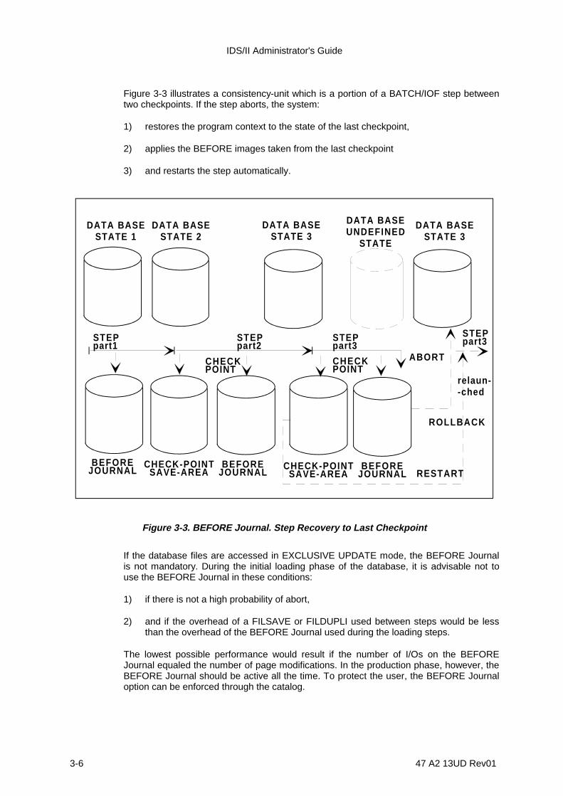
IDS/II Administrator's Guide
3-6 47 A2 13UD Rev01
Figure 3-3 illustrates a consistency-unit which is a portion of a BATCH/IOF step betweentwo checkpoints. If the step aborts, the system:
1) restores the program context to the state of the last checkpoint,
2) applies the BEFORE images taken from the last checkpoint
3) and restarts the step automatically.
CHECKPOINT
STEPpart1
STEPpart2
STEPpart3
CHECKPOINT
ROLLBACK
ABORT
DATA BASESTATE 1
DATA BASESTATE 2
DATA BASESTATE 3
DATA BASESTATE 3
DATA BASEUNDEFINED
STATE
RESTARTBEFORE
JOURNALCHECK-POINT
SAVE-AREABEFORE
JOURNALCHECK-POINT
SAVE-AREABEFORE
JOURNAL
relaun--ched
STEPpart3
Figure 3-3. BEFORE Journal. Step Recovery to Last Checkpoint
If the database files are accessed in EXCLUSIVE UPDATE mode, the BEFORE Journalis not mandatory. During the initial loading phase of the database, it is advisable not touse the BEFORE Journal in these conditions:
1) if there is not a high probability of abort,
2) and if the overhead of a FILSAVE or FILDUPLI used between steps would be lessthan the overhead of the BEFORE Journal used during the loading steps.
The lowest possible performance would result if the number of I/Os on the BEFOREJournal equaled the number of page modifications. In the production phase, however, theBEFORE Journal should be active all the time. To protect the user, the BEFORE Journaloption can be enforced through the catalog.

Database Integrity
47 A2 13UD Rev01 3-7
If the database files are accessed in MONITORED UPDATE mode, the BEFORE Journalis mandatory so that potential deadlocks can be rectified. GAC checks that the BEFOREJournal is present at OPEN time.
NOTE: If the database files are accessed exclusively by a TDS transaction(ACCESS=SPWRITE), the BEFORE Journal may be replaced by a combinationof the AFTER Journal and the DEFERRED UPDATES mechanism. Thissubstitution is only possible if the number of buffers is large enough toaccommodate all the pages modified by the commitment-unit.
The BEFORE Journal is a system-wide file located on the system disk. This file is dividedinto several subfiles, each subfile corresponding to one active consistency-unit. A subfileis reinitialized each time a consistency-unit successfully terminates an execution. If theconsistency-unit terminates abnormally, the subfile is first reread in reverse chronologicalorder for the application of BEFORE images, then reinitialized. The BEFORE Journal canbe extended automatically by the system.
With the BEFORE Journal, a deferred restart cannot be performed. It is also impossible toreturn to a consistency-point earlier than the most recent one.
IDS/II Administrator's Guide
3-8 47 A2 13UD Rev01
3.4 AFTER JOURNAL
The purpose of the AFTER Journal is to provide a global recovery point later than themost recent global consistency-point set by the FILSAVE or FILDUPLI Utility.
The AFTER Journal keeps an incremental record of the page modifications which aremade by consistency-units between two complete saves of the database. The AFTERJOURNAL keeps records in the form of images of the portions of pages which have beenmodified. The AFTER images corresponding to successfully executed consistency-unitsare termed valid. Images corresponding to abnormally terminated consistency-units aretermed invalid.
If a hardware incident destroys the database at time t3, the database is restored by theFILREST or FILDUPLI Utility onto a new disk, to the state of the last save. Then, theROLLFWD Utility is executed to reinstitute the valid AFTER images which reflect the stateof the database between the last save (time t1) up to time t2, which is before or equal totime t3. Please refer to Figure 3-4.
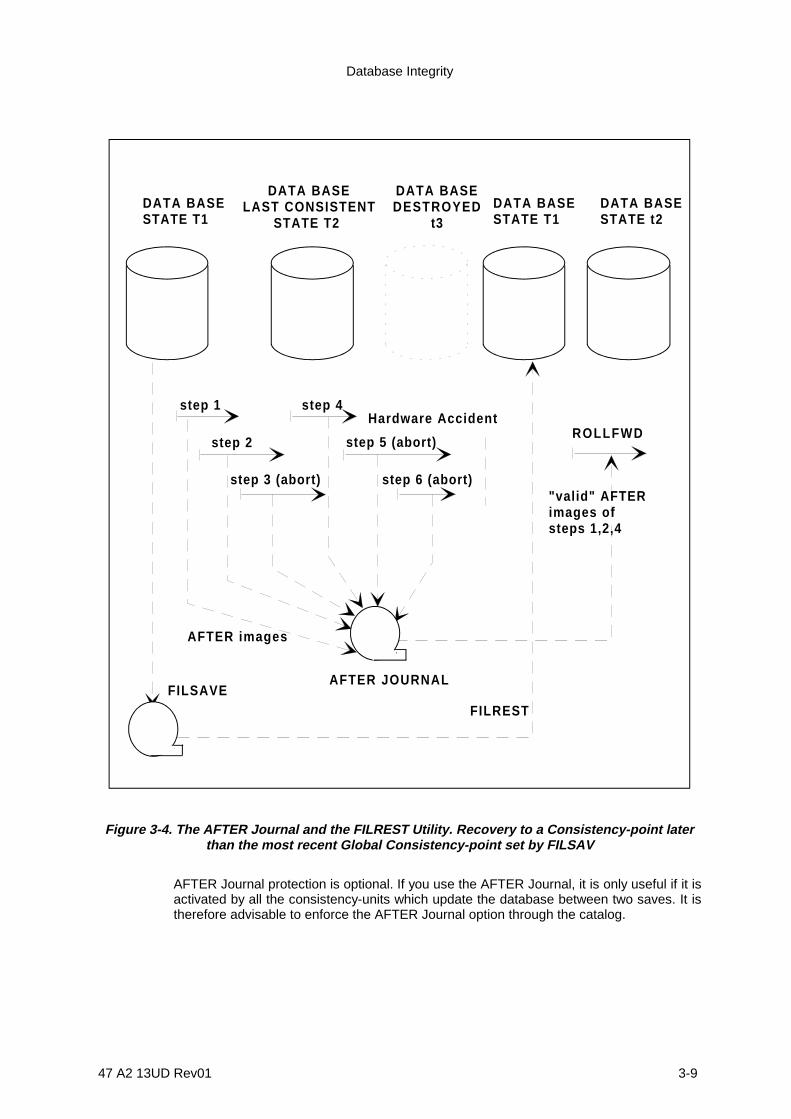
Database Integrity
47 A2 13UD Rev01 3-9
step 1
step 2
step 3 (abort)
step 4
step 5 (abort)
step 6 (abort)
ROLLFWD
"valid" AFTERimages ofsteps 1,2,4
AFTER JOURNAL
FILRESTFILSAVE
AFTER images
Hardware Accident
DATA BASESTATE T1
DATA BASELAST CONSISTENT
STATE T2
DATA BASEDESTROYED
t3DATA BASESTATE T1
DATA BASESTATE t2
Figure 3-4. The AFTER Journal and the FILREST Utility. Recovery to a Consistency-point laterthan the most recent Global Consistency-point set by FILSAV
AFTER Journal protection is optional. If you use the AFTER Journal, it is only useful if it isactivated by all the consistency-units which update the database between two saves. It istherefore advisable to enforce the AFTER Journal option through the catalog.

IDS/II Administrator's Guide
3-10 47 A2 13UD Rev01
The AFTER Journal is system-wide. It applies to all the files which are protected by thesystem. It is composed of a directory residing on disk and several journal files residing ondisk or tape. Since AFTER Journal protection is intended mainly for recovery fromhardware accidents, it is essential that the AFTER Journal and directory files reside onmedia other than those which contain the database.
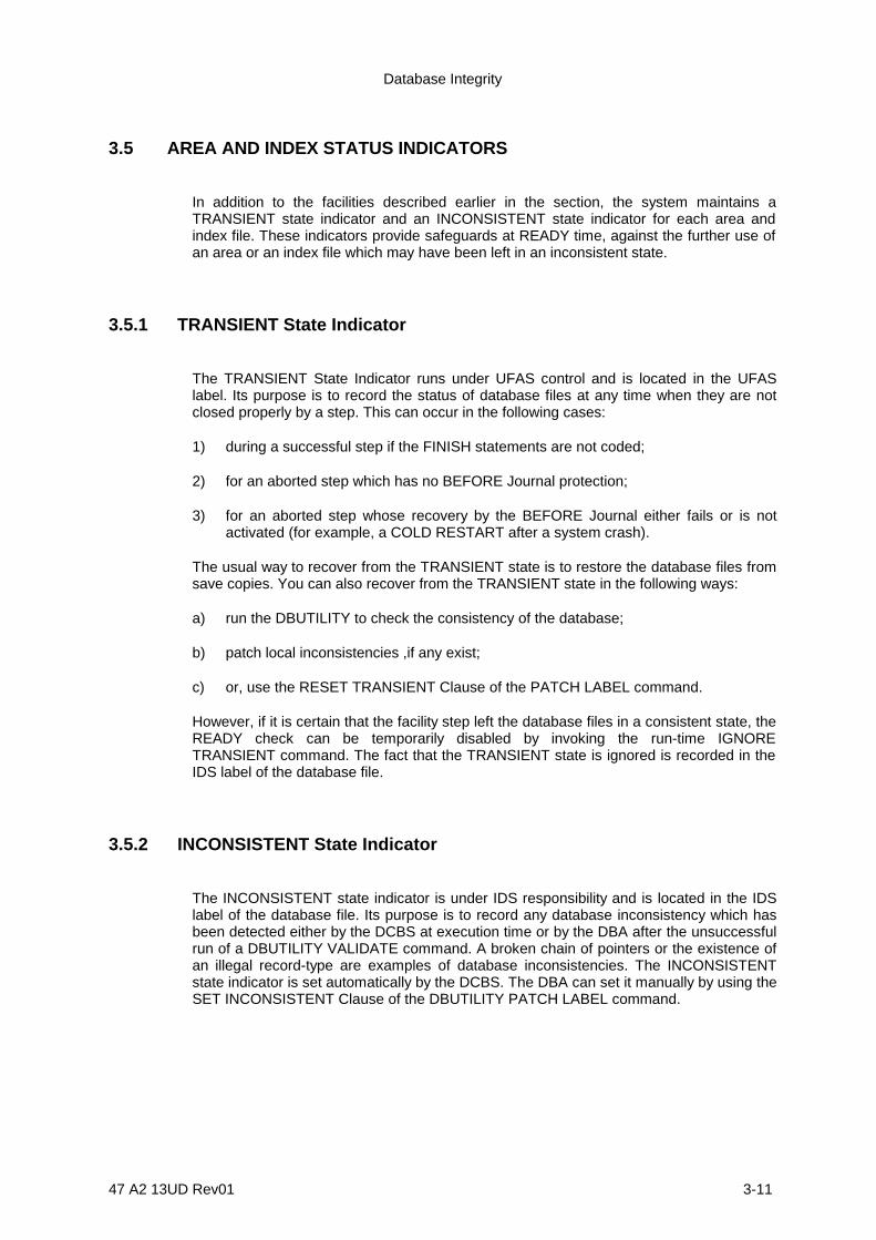
Database Integrity
47 A2 13UD Rev01 3-11
3.5 AREA AND INDEX STATUS INDICATORS
In addition to the facilities described earlier in the section, the system maintains aTRANSIENT state indicator and an INCONSISTENT state indicator for each area andindex file. These indicators provide safeguards at READY time, against the further use ofan area or an index file which may have been left in an inconsistent state.
3.5.1 TRANSIENT State Indicator
The TRANSIENT State Indicator runs under UFAS control and is located in the UFASlabel. Its purpose is to record the status of database files at any time when they are notclosed properly by a step. This can occur in the following cases:
1) during a successful step if the FINISH statements are not coded;
2) for an aborted step which has no BEFORE Journal protection;
3) for an aborted step whose recovery by the BEFORE Journal either fails or is notactivated (for example, a COLD RESTART after a system crash).
The usual way to recover from the TRANSIENT state is to restore the database files fromsave copies. You can also recover from the TRANSIENT state in the following ways:
a) run the DBUTILITY to check the consistency of the database;
b) patch local inconsistencies ,if any exist;
c) or, use the RESET TRANSIENT Clause of the PATCH LABEL command.
However, if it is certain that the facility step left the database files in a consistent state, theREADY check can be temporarily disabled by invoking the run-time IGNORETRANSIENT command. The fact that the TRANSIENT state is ignored is recorded in theIDS label of the database file.
3.5.2 INCONSISTENT State Indicator
The INCONSISTENT state indicator is under IDS responsibility and is located in the IDSlabel of the database file. Its purpose is to record any database inconsistency which hasbeen detected either by the DCBS at execution time or by the DBA after the unsuccessfulrun of a DBUTILITY VALIDATE command. A broken chain of pointers or the existence ofan illegal record-type are examples of database inconsistencies. The INCONSISTENTstate indicator is set automatically by the DCBS. The DBA can set it manually by using theSET INCONSISTENT Clause of the DBUTILITY PATCH LABEL command.

IDS/II Administrator's Guide
3-12 47 A2 13UD Rev01
The usual way to recover from the INCONSISTENT state is to restore the database filesfrom save copies. Another way is to patch the inconsistent part of the database afteranalyzing the error message which reports the inconsistency. The error message is senteither by the DCBS or the DBUTILITY. After analyzing the message, you must validate thepatch and, if the validation is successful, use the RESET INCONSISTENT Clause of thePATCH LABEL command.
However, if it is certain that the program will not work on the inconsistent part of thedatabase, the READY check can be temporarily disabled by the use of the run-timeIGNORE INCONSISTENT command. The fact that the INCONSISTENT state is ignoredis recorded in the IDS label.
Database Integrity
47 A2 13UD Rev01 3-13
3.6 DATABASE VALIDITY CHECKS
The structure of a database is complex. Therefore, it is essential to detect any potentialcorruption as soon as possible. Validity checks can be performed by the DBCS, byDBUTILITY and by user-written programs. Those performed by the DBCS andDBUTILITY are limited to the structure of the database as defined in the schema. Thoseperformed by user-written programs are directed to parts of the structure which are notdefined in the schema but are essentially programming rules for the transactionsaccessing the database.
3.6.1 DBCS Validity Checks
DBCS validity checks fall into three categories:
1) The first category includes permanent checks that are essential to the properexecution of DBCS algorithms. These checks exist to maintain consistency betweenthe IDS components which cooperate during database operations. Such componentsinclude the schema, the subschema, programs, and the database itself. Thesevalidity checks also exist to maintain the internal consistency of the database,especially the consistency of pointers between pages and between areas andindexes.
2) The second category includes permanent checks which are not essential to theDBCS algorithms but which safeguard against potential errors which are internal tothe IDS software.
3) The third category includes optional checks which validate the structure of databasepages being read and/or modified by the run-unit. These checks are triggered by theCHECK PAGE STRUCTURE command, which is a run-time command.
3.6.2 DBUTILITY Validity Checks
The DBUTILITY provides three kinds of validation:
1) A global validation, which is directed to complete areas. This validation checks thepointers of all occurrences of one or more set-types and the consistency of all CALC-chains. The method applied in this kind of validation forbids any concurrent update.
The global validation can take a long time. It should, nevertheless, be performed asa preventive measure prior to certain FILSAVE or FILDUPLI operations. Such aglobal validation will preclude the possibility of save copies being generated whichcontain inconsistent copies of the database.

IDS/II Administrator's Guide
3-14 47 A2 13UD Rev01
2) The local validation is directed to one or more pages. It checks:
- the UFAS page structure,
- the IDS structure of the storage records contained in the page,
- and, optionally, set pointers which point outside of the page.
Since the local validation is limited to a few pages, it can be performed whileconcurrent run-units update other pages of the database. The local validation isa means of investigating database inconsistencies which the DBCS hasdiscovered, or which the DBUTILITY global validation has found. It is also ameans of validating the DBUTILITY patch.
3) The rebuilding of secondary keys. This ensures the integrity between areas andindex files.
3.6.3 User Validity Checks
The DBUTILITY may be complemented by user-written validation programs. Suchprograms can help ensure that the constraints of the user data are satisfied. For example,if the value of a field in the owner of a set occurrence should represent the sum of thefield-values in the member of this set occurrence, a user-written validation program cancheck that these constraints are respected. User validation programs should beparameterized to allow a choice between a global and a local validation.

Database Integrity
47 A2 13UD Rev01 3-15
3.7 DATABASE PATCH FACILITY
When a local database inconsistency has been discovered and analyzed, a globalrestoration from save copies is possible. You can also patch the database, in which casea global restoration is not necessary. The DBUTILITY provides the means to modify thestorage area at the page or record level. A modification at the page level is necessary ifthe UFAS structure of the page (which include the page header, record locators and OWLrecords) is corrupted. A modification at the record level is recommended if the UFASstructure of the page is correct and if the modification is local to the record.
The patch facility should be used with caution. It should be followed by a local validation inthe same consistency-unit. This implies the use of the VALIDATE PAGELOCALLY/GLOBALLY command between two COMMIT commands. If the validation fails,the ROLLBACK command can be used to invalidate the modifications by restoring thedatabase to the state it was in at the last commitment-point.
The patch facility is available in EXCLUSIVE or MONITORED mode, depending on theASSIGN parameters. The database file protection options (BEFORE and/or AFTERjournal) should be the same as for any user step accessing the date base. If the area orindex file to be patched is catalogued, the user must have the RECOVERY rights toexecute the PATCH command.
The fact that the database has been patched is recorded in the IDS label.

IDS/II Administrator's Guide
3-16 47 A2 13UD Rev01
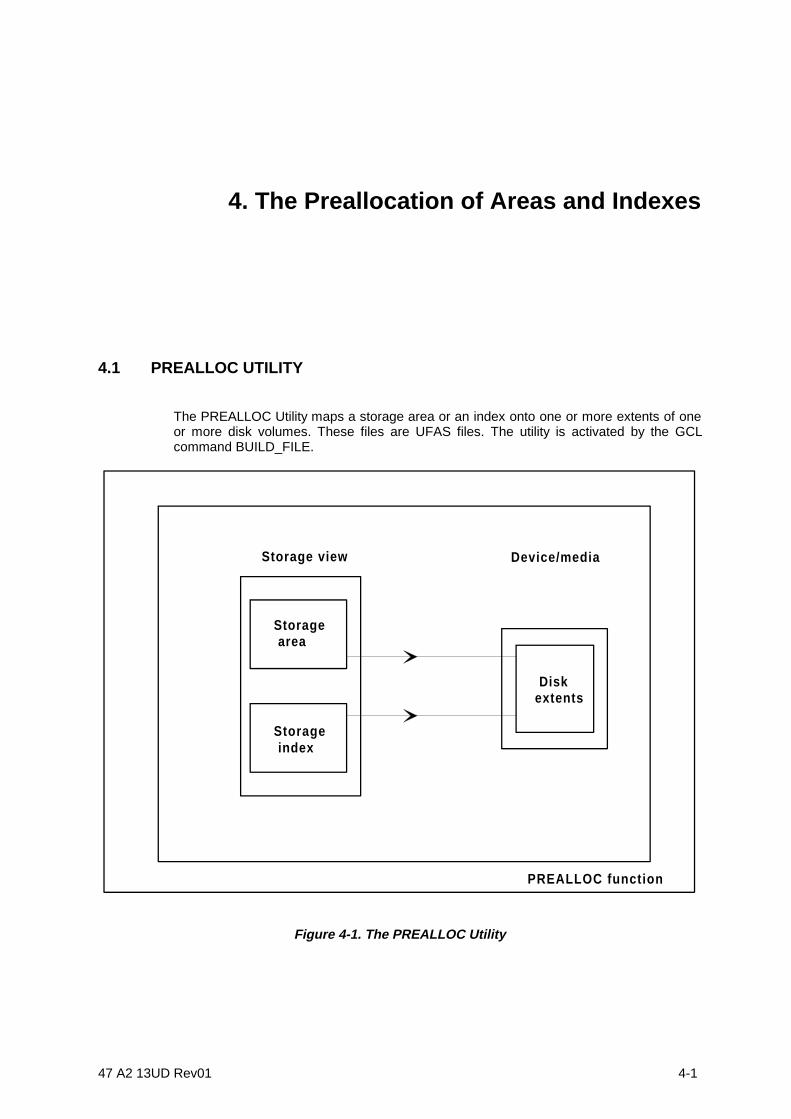
47 A2 13UD Rev01 4-1
4. The Preallocation of Areas and Indexes
4.1 PREALLOC UTILITY
The PREALLOC Utility maps a storage area or an index onto one or more extents of oneor more disk volumes. These files are UFAS files. The utility is activated by the GCLcommand BUILD_FILE.
Storage view Device/media
Diskextents
Storage area
Storage index
PREALLOC function
Figure 4-1. The PREALLOC Utility

IDS/II Administrator's Guide
4-2 47 A2 13UD Rev01
The PREALLOC Utility must be invoked for each storage area or index file of thedatabase.

The Preallocation of Areas and Indexes
47 A2 13UD Rev01 4-3
The utility retrieves the characteristics of the storage area or index file from the objectschema, which must be in the DDL-DMCL state at the time of retrieval. For a storagearea, these characteristics include the number of pages, the number of lines per page, thepage size and the CALC interval. For an index file, they include the number of pages andthe page size.
The main parameters which must be supplied directly to the PREALLOC Utility are:
1) the external-file-names, which identify the occurrences of the storage area or theindex file,
2) the device type of the disk,
3) the names of the volumes where space is to be reserved,
4) optionally, the amount of space which will be needed on each volume and theposition of the allocation on the disk.
IDS/II Administrator's Guide
4-4 47 A2 13UD Rev01
4.2 SPACE ALLOCATION
1. To determine the allocation of space, the PREALLOC Utility calculates the totalnumber of suitable allocation units for the specified device class of the file. For thiscalculation, the utility uses the following DMCL information: number of pages(NUMP) and page size. This calculation is performed automatically. However, foradministrative purposes, the user should know how many tracks will be required.Suitable allocation units can be one of the following:
- cylinders (CYL),- tracks (TRACK),- file blocks (BLOCK),- or a 100-byte quantum (100 KB).
2. Space is allocated as a series of one or more extents. An extent is a group of one ormore contiguous allocation units. On any one volume, a file can have up to 16extents. However, for general efficiency, the user can restrict the number of extentsper volume to less than the maximum (16).
3. In the automatic mode of allocation, the user need only specify the list of volumes onwhich the area or the index resides.
4. The following mode of allocation exists which is less automatic: for each volume, theuser specifies the amount of space to be allocated. Using this simple method, theallocation simply fails if this amount of space is not available on the volume or if thenumber of extents required is larger than the maximum allowable number.
Using this mode of allocation, the user may also specify the disk address of theallocation. A sufficient amount of contiguous free space must exist at the suppliedaddress if you want to allocate on a single extent the desired amount of space.
5. The space allocated is formatted by PREALLOC. For each page, a page header anda CALC chain OWL record (for storage areas) are written. The remainder of thepage is filled with binary zeroes.
6. PREALLOC also creates the standard UFAS labels and specific IDS labels. The IDSlabels contain the following:
- the name and DMCL reference date of the schema used for the preallocation,- the storage area or index name and its DMCL characteristics.
At run-time, the above information must match the corresponding information in theschema which is loaded for execution.
For further information on space allocation, please refer to the Data ManagementUtilities User's Guide.

The Preallocation of Areas and Indexes
47 A2 13UD Rev01 4-5
4.3 PREALLOC GCL STATEMENT
The PREALLOC Utility can be invoked in interactive mode using the BUILD_FILEcommand at the IOF level by using the following statement:
BUILD_FILE
FILE = external-file-name
[ { CAT } ][ FILESTAT = { UNCAT } ][ { TEMPRY } ]
[ { ddd } ][ EXPDATE = { yy/ddd } ][ { yy/mm/dd } ]
UFAS = IDS
[ { 5 } ][ MAXEXT = { } ][ { integer-1 } ]
DDLIB1 = library-description
[ { AREA = area-name } ][ { INDEX = index-name } ]
SCHEMA = schema-name
[ { 0 } ][ SILENT = { 1 } ]
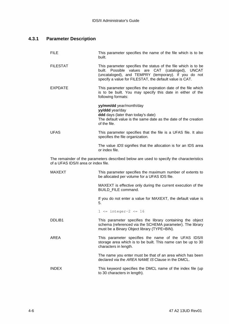
IDS/II Administrator's Guide
4-6 47 A2 13UD Rev01
4.3.1 Parameter Description
FILE This parameter specifies the name of the file which is to bebuilt.
FILESTAT This parameter specifies the status of the file which is to bebuilt. Possible values are CAT (cataloged), UNCAT(uncataloged), and TEMPRY (temporary). If you do notspecify a value for FILESTAT, the default value is CAT.
EXPDATE This parameter specifies the expiration date of the file whichis to be built. You may specify this date in either of thefollowing formats:
yy/mm/dd year/month/dayyy/ddd year/dayddd days (later than today's date)The default value is the same date as the date of the creationof the file.
UFAS This parameter specifies that the file is a UFAS file. It alsospecifies the file organization.
The value IDS signifies that the allocation is for an IDS areaor index file.
The remainder of the parameters described below are used to specify the characteristicsof a UFAS IDS/II area or index file.
MAXEXT This parameter specifies the maximum number of extents tobe allocated per volume for a UFAS IDS file.
MAXEXT is effective only during the current execution of theBUILD_FILE command.
If you do not enter a value for MAXEXT, the default value is5.
1 <= integer-2 <= 16
DDLIB1 This parameter specifies the library containing the objectschema (referenced via the SCHEMA parameter). The librarymust be a Binary Object library (TYPE=BIN).
AREA This parameter specifies the name of the UFAS IDS/IIstorage area which is to be built. This name can be up to 30characters in length.
The name you enter must be that of an area which has beendeclared via the AREA NAME IS Clause in the DMCL.
INDEX This keyword specifies the DMCL name of the index file (upto 30 characters in length).

The Preallocation of Areas and Indexes
47 A2 13UD Rev01 4-7
The name you enter must be that of an index which has beendeclared via the INDEX NAME IS Clause in the DMCL.
IDS/II Administrator's Guide
4-8 47 A2 13UD Rev01
SCHEMA This parameter specifies the name of the schema where theUFAS IDS/II storage area or index file to be built is defined.The storage area or index file is referenced via the AREA orINDEX parameter.
The schema, which is written in both DDL and DMCL,describes the logical and physical structures of the database.
To correctly specify this parameter, you must enter the nameof an existing schema (up to 30 characters long).
SILENT This parameter indicates whether or not the BUILD_FILEcommand is to execute in silent mode.
In the silent mode, no messages will appear at your terminalif the command executes successfully. You are informed ofthe successful execution of the command by the appearanceof the next prompt.
However, if the execution is not successful, an error messageappears at your terminal.
If you do not enter a value for SILENT, the default is 0 (allmessages appear at the terminal).

The Preallocation of Areas and Indexes
47 A2 13UD Rev01 4-9
4.4 PREALLOC EXTENDED JCL STATEMENT
4.4.1 PREALLOC General Format
PREALLOC can be invoked using the following extended JCL statement:
PREALLOC external-file-name{ { CAT } }{ {FILESTATE = { UNCAT } }{ {TEMPRY } }{ TEMPRY} }
[ CATALOG = integer-1 ] [ CATNOW ]
[ { ddd } ][ EXPDATE = { yy/ddd } ][ { yy/mm/dd } ]
[ { BLOCK } ][ UNIT = { CYL } ][ { TRACK } ][ { 100KB } ]
[ { 5 } ][ MAXEXT = { } ][ { integer-2 } ]
{ RESIDENT }{ DEVCLASS = device-class }{ { GLOBAL = ( MEDIA = ( volume-name [ volume-name ] ... ) ) } }{ { } }{ { SPLIT = ( ( volume-name SIZE = integer-3 } }{ { [ disk address ] ) } }{ { [ ( volume-name SIZE = int-4 } }{ { [ disk address ] ) ] ... ) } }
{ AREA = area-name }UFAS = ( IDS = ( { INDEX = index-name } SCHEMA = schema-name DDLIB1 = ( library-description ) ) ) ;
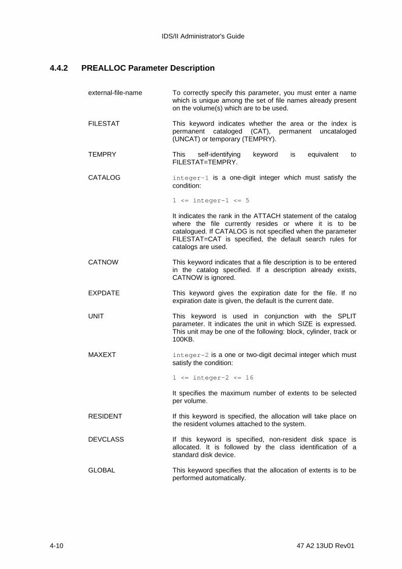
IDS/II Administrator's Guide
4-10 47 A2 13UD Rev01
4.4.2 PREALLOC Parameter Description
external-file-name To correctly specify this parameter, you must enter a namewhich is unique among the set of file names already presenton the volume(s) which are to be used.
FILESTAT This keyword indicates whether the area or the index ispermanent cataloged (CAT), permanent uncataloged(UNCAT) or temporary (TEMPRY).
TEMPRY This self-identifying keyword is equivalent toFILESTAT=TEMPRY.
CATALOG integer-1 is a one-digit integer which must satisfy thecondition:
1 <= integer-1 <= 5
It indicates the rank in the ATTACH statement of the catalogwhere the file currently resides or where it is to becatalogued. If CATALOG is not specified when the parameterFILESTAT=CAT is specified, the default search rules forcatalogs are used.
CATNOW This keyword indicates that a file description is to be enteredin the catalog specified. If a description already exists,CATNOW is ignored.
EXPDATE This keyword gives the expiration date for the file. If noexpiration date is given, the default is the current date.
UNIT This keyword is used in conjunction with the SPLITparameter. It indicates the unit in which SIZE is expressed.This unit may be one of the following: block, cylinder, track or100KB.
MAXEXT integer-2 is a one or two-digit decimal integer which mustsatisfy the condition:
1 <= integer-2 <= 16
It specifies the maximum number of extents to be selectedper volume.
RESIDENT If this keyword is specified, the allocation will take place onthe resident volumes attached to the system.
DEVCLASS If this keyword is specified, non-resident disk space isallocated. It is followed by the class identification of astandard disk device.
GLOBAL This keyword specifies that the allocation of extents is to beperformed automatically.

The Preallocation of Areas and Indexes
47 A2 13UD Rev01 4-11
MEDIA This parameter is followed by a list of one or more volumenames to be used in the acquisition of space. The order ofthe list is important: the utility will allocate the maximumnumber of extents (see MAXEXT above) on the first volumementioned on the list, and then proceed to the second andthird, etc.. This operation continues until sufficient extents areallocated.
In the case of a multi-volume allocation, it is possible that thespace requirement for the file will be satisfied without all thevolumes being needed. If they are not all needed, the utilitywill not use the last volumes. Therefore, they need not bementioned in future references to the file.
The volume names given must be in the desired order ofusage. The pages with the lowest page numbers will berecorded on the first volume and the pages with the highestpage numbers on the last volume.
SPLIT This keyword specifies that the allocation is to be performedon a volume-by-volume basis. It is followed by a parametergroup which lists each volume and the amount of spacerequired on each. Optionally, for each volume, the user mayspecify the disk address where allocation is to occur. Youneed not specify addresses for all volumes.
The volume names given must be in the desired order ofusage. The pages with the lowest page numbers will berecorded on the first volume and the pages with the highestpage numbers on the last volume.
SIZE This keyword, which is supplied with each volume name,gives the amount of space required on the volume. Thenumeric value supplied, which can be up to five digits long, isexpressed in the unit specified by the keyword UNIT.
disk address This optional keyword may be either CYL (TRACK) orDATABLK, depending on the volume organization. For furtherinformation on this topic, please refer to the DataManagement Utilities User's Guide.
UFAS This keyword is followed by a parameter group which definesthe file characteristics.
IDS This keyword signifies that the allocation is for an IDS area orindex file.
AREA This keyword specifies the DMCL name of the storage area(up to 30 characters in length).
INDEX This keyword specifies the DMCL name of the index file (upto 30 characters in length).
SCHEMA This keyword specifies the name of the schema where thestorage area or index is defined.
DDLIB1 This keyword is followed by a parameter group whichidentifies the library containing the object schema.

IDS/II Administrator's Guide
4-12 47 A2 13UD Rev01

The Preallocation of Areas and Indexes
47 A2 13UD Rev01 4-13

47 A2 13UD Rev01 5-1
5. Database Utility Common Functions
5.1 DBUTILITY COMMON FUNCTIONS
The common functions of the Database Utility are:
1) to define the destination of the DBUTILITY report,
2) to specify the object schema to which subsequent specific commands apply,
3) to define consistency-points,
4) to restore the database to the state it was in at the last consistency-point,
5) to control the flow of DBUTILITY commands,
6) to enable the analysis of an upcoming command without executing that command,
7) to help the interactive user to remenber the command syntax,
8) to terminate the current DBUTILITY session.
IDS/II Administrator's Guide
5-2 47 A2 13UD Rev01
5.2 DBUTILITY COMMON COMMAND LANGUAGE
5.2.1 Syntax Conventions
The syntax rules, reserved words and descriptive notation are described in the preface ofthis manual.
5.2.2 Types of command
Eight commands are described in this section:
• DISPLAY• SCHEMA• COMMIT• ROLLBACK• STATUS• OPTION• HELP• QUIT or "/"

Database Utility Common Functions
47 A2 13UD Rev01 5-3
5.3 DISPLAY COMMAND
5.3.1 Function
To define the destinations of the DBUTILITY report.
5.3.2 General Format
| SYSOUT |DISPLAY UPON | | . | TERMINAL |
5.3.3 Rules
1. In a BATCH environment, the DISPLAY command is ignored; the default value isDISPLAY UPON SYSOUT.
2. In IOF environment, three destinations are possible:
- If SYSOUT only is specified, the main destination is the SYSOUT file.
- If TERMINAL only is specified, the main destination is the terminal.
- If SYSOUT and TERMINAL are specified, the main destination is the terminaland the SYSOUT file is a copy of the TERMINAL report.
For more detailed information on the contents and format of the reports, see Tables1-1 and 1-2 in Section 1 of this manual.
3. In an IOF environment, the default option is DISPLAY UPON TERMINAL. TheDISPLAY command may be entered several times with different options during anIOF session.
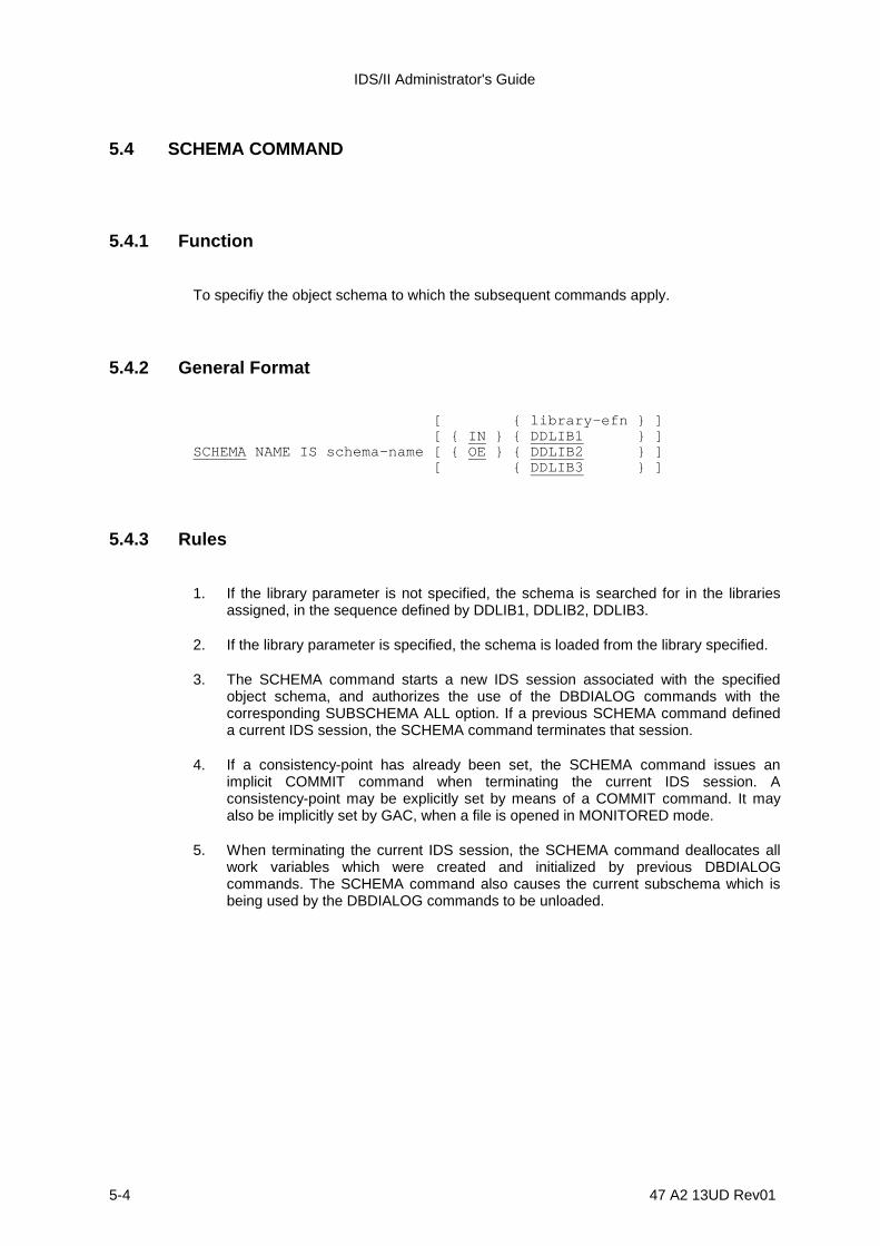
IDS/II Administrator's Guide
5-4 47 A2 13UD Rev01
5.4 SCHEMA COMMAND
5.4.1 Function
To specifiy the object schema to which the subsequent commands apply.
5.4.2 General Format
[ { library-efn } ] [ { IN } { DDLIB1 } ]SCHEMA NAME IS schema-name [ { OE } { DDLIB2 } ] [ { DDLIB3 } ]
5.4.3 Rules
1. If the library parameter is not specified, the schema is searched for in the librariesassigned, in the sequence defined by DDLIB1, DDLIB2, DDLIB3.
2. If the library parameter is specified, the schema is loaded from the library specified.
3. The SCHEMA command starts a new IDS session associated with the specifiedobject schema, and authorizes the use of the DBDIALOG commands with thecorresponding SUBSCHEMA ALL option. If a previous SCHEMA command defineda current IDS session, the SCHEMA command terminates that session.
4. If a consistency-point has already been set, the SCHEMA command issues animplicit COMMIT command when terminating the current IDS session. Aconsistency-point may be explicitly set by means of a COMMIT command. It mayalso be implicitly set by GAC, when a file is opened in MONITORED mode.
5. When terminating the current IDS session, the SCHEMA command deallocates allwork variables which were created and initialized by previous DBDIALOGcommands. The SCHEMA command also causes the current subschema which isbeing used by the DBDIALOG commands to be unloaded.

Database Utility Common Functions
47 A2 13UD Rev01 5-5
5.5 COMMIT COMMAND
5.5.1 Functions
1) To terminate the current commitment-unit, if any
2) To unlock reserved pages and make commitment-unit updates definitive andconsequently available to other concurrent-units.
3) To initiate a new commitment-unit.
5.5.2 General Format
COMMIT [WITH n LOCK-ENTRIES ] .
5.5.3 Syntax Rules
1. n designates the maximum number of lock entries for the initiated commitment-unit.It must be written as an unsigned decimal integer other than 0.
5.5.4 General Rules
1. When General Access Control (GAC) is active, the COMMIT command defines theend of the current commitment-unit, if any, and the beginning of the nextcommitment-unit.
2. When GAC is not active, the COMMIT function has the same effect as aCHECKPOINT command. The command has no effect if the REPEAT option has notbeen specified in the STEP statement.
In a non-concurrent access environment, the COMMIT function is only effective inupdate mode when the BEFORE Journal is active. In this case, the commandinvalidates unsuccessful or unwanted update commands such as PATCH, BUILD-KEY, DELETE-KEY, STORE, MODIFY, CONNECT, DISCONNECT or ERASE.
3. If the LOCK-ENTRIES Clause is specified, it defines the maximum number of pageswhich can be locked during the initiated commitment-unit. This is only relevant whenGAC is active. The use of this clause can be useful during a commitment-unit whenthe commands are spread over a high number of randomly accessed pages of thedatabase.

IDS/II Administrator's Guide
5-6 47 A2 13UD Rev01
4. If the LOCK-ENTRIES Clause is not specified, the maximum number of lock entriesremains at its default value. This default value is either 100, if it has not beenredefined by a previous COMMIT command, or the value defined by the lastCOMMIT command which contained a LOCK-ENTRIES Clause.
5. When GAC is activated, an implicit COMMIT command is issued with a maximumnumber of 100 lock entries. At GAC activation time (from an inactive state), the stepswitches from a state where there were no files open in MONITORED mode to astate in which at least one file is open in MONITORED mode.
When GAC becomes active, an implicit COMMIT command is issued with amaximum number of 100 lock entries.
6. When GAC is deactivated, the step returns to a state where no files are open inMONITORED mode, and a COMMIT command is issued either explicitly, or elseimplicitly by a SCHEMA command.
GAC is never active when a step is launched.
7. In update mode, you can return the database to the state it was in at the lastconsistency-point by using the ROLLBACK command. The last consistency-pointcan be either a commitment-point or a checkpoint.
8. The execution of the COMMIT command modifies the currency indicators used byDBDIALOG functions in the same way as a user COBOL program. Please refer tothe IDS/II User's Guide and to the Full IDS/II Refernce Manual Volume II for furtherinformation.
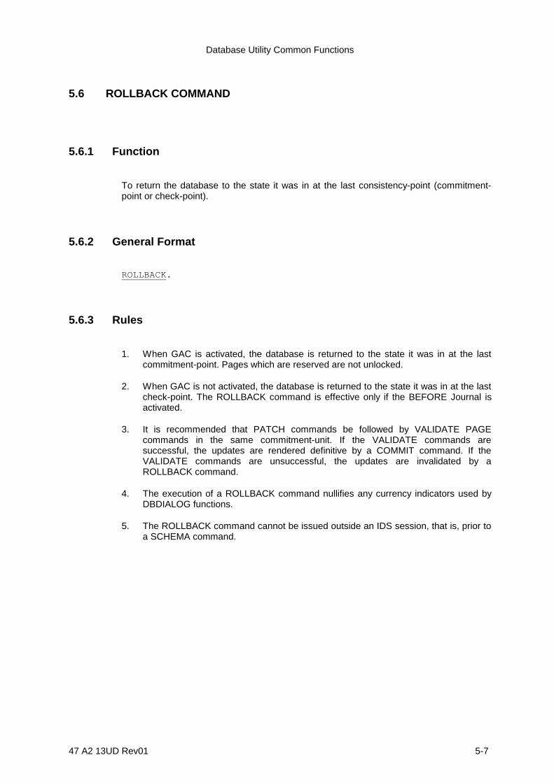
Database Utility Common Functions
47 A2 13UD Rev01 5-7
5.6 ROLLBACK COMMAND
5.6.1 Function
To return the database to the state it was in at the last consistency-point (commitment-point or check-point).
5.6.2 General Format
ROLLBACK.
5.6.3 Rules
1. When GAC is activated, the database is returned to the state it was in at the lastcommitment-point. Pages which are reserved are not unlocked.
2. When GAC is not activated, the database is returned to the state it was in at the lastcheck-point. The ROLLBACK command is effective only if the BEFORE Journal isactivated.
3. It is recommended that PATCH commands be followed by VALIDATE PAGEcommands in the same commitment-unit. If the VALIDATE commands aresuccessful, the updates are rendered definitive by a COMMIT command. If theVALIDATE commands are unsuccessful, the updates are invalidated by aROLLBACK command.
4. The execution of a ROLLBACK command nullifies any currency indicators used byDBDIALOG functions.
5. The ROLLBACK command cannot be issued outside an IDS session, that is, prior toa SCHEMA command.
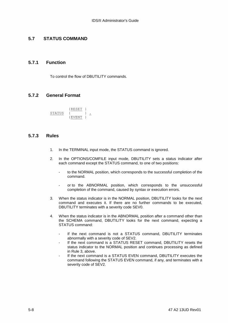
IDS/II Administrator's Guide
5-8 47 A2 13UD Rev01
5.7 STATUS COMMAND
5.7.1 Function
To control the flow of DBUTILITY commands.
5.7.2 General Format
{RESET }STATUS { } . {EVENT }
5.7.3 Rules
1. In the TERMINAL input mode, the STATUS command is ignored.
2. In the OPTIONS/COMFILE input mode, DBUTILITY sets a status indicator aftereach command except the STATUS command, to one of two positions:
- to the NORMAL position, which corresponds to the successful completion of thecommand.
- or to the ABNORMAL position, which corresponds to the unsuccessfulcompletion of the command, caused by syntax or execution errors.
3. When the status indicator is in the NORMAL position, DBUTILITY looks for the nextcommand and executes it. If there are no further commands to be executed,DBUTILITY terminates with a severity code SEV0.
4. When the status indicator is in the ABNORMAL position after a command other thanthe SCHEMA command, DBUTILITY looks for the next command, expecting aSTATUS command:
- If the next command is not a STATUS command, DBUTILITY terminatesabnormally with a severity code of SEV2.
- If the next command is a STATUS RESET command, DBUTILITY resets thestatus indicator to the NORMAL position and continues processing as definedin Rule 3, above.
- If the next command is a STATUS EVEN command, DBUTILITY executes thecommand following the STATUS EVEN command, if any, and terminates with aseverity code of SEV2.

Database Utility Common Functions
47 A2 13UD Rev01 5-9
5. When the status indicator is in the ABNORMAL position after a SCHEMA command,processing proceeds as described in Rule 4 with the following exception: if aSTATUS command follows, DBUTILITY resynchronizes to the next possibleSCHEMA command, skipping all the commands related to the previous SCHEMAcommand.
6. A STATUS command is ignored if the status indicator is already in the NORMALposition.
7. If an internal irrecoverable error occurs while DBUTILITY is processing a command,this command is aborted and DBUTILITY terminates with a severity code SEV4,irrespective of any subsequent STATUS command.
8. When the current execution is for analysis only, due to a previous OPTIONNOEXECUTE command, the STATUS command is ignored.

IDS/II Administrator's Guide
5-10 47 A2 13UD Rev01
5.8 OPTION COMMAND
5.8.1 Function
To enable or disable the execution of subsequent commands.
5.8.2 General Format
{ EXECUTE }OPTION IS { } . { NOEXECUTE }
5.8.3 Rules
1. The EXECUTE option is valid for all subsequent commands until another OPTIONcommand is encountered.
2. When NOEXECUTE is specified, subsequent commands are analyzed but only theSCHEMA, SUBSCHEMA and DISPLAY commands are executed. SubsequentSTATUS commands are ignored.
3. When EXECUTE is specified, all subsequent commands are analyzed and, ifcorrect, executed.
4. At the launching of the DBUTILITY session, the default option is EXECUTE.

Database Utility Common Functions
47 A2 13UD Rev01 5-11
5.9 HELP COMMAND
5.9.1 Function
To display the syntax of a specified command.
5.9.2 General Format
[ ACCEPT ] [ ANALYZE ] [ BUILD-KEY ] [ CONNECT ] [ DELETE-KEY ] [ DISCONNECT ] [ ERASE ] [ FIND ] [ FINISH ] [ GET ] [ LIST ] [ MODIFY ] [ MOVE ]HELP [ PATCH ] . [ PRINT LABEL ] [ PRINT PAGE ] [ PRINT RECORD ] [ READY ] [ RECONNECT ] [ SIMULOAD ] [ SORT ] [ STORE ] [ SUBSCHEMA ] [ VALIDATE PAGE ] [ VALIDATE POINTERS ] [ VALIDATE CALC -CHAIN ] [ VALIDATE CHECK ]
5.9.3 Rules
1. The syntax of the specified command is displayed.
2. When no command is specified, the syntax of the common functions is displayed.
3. This command is ignored in a batch environment.
4. In an IOF environment, the desired syntax is displayed on the terminal regardless ofthe current DISPLAY option.
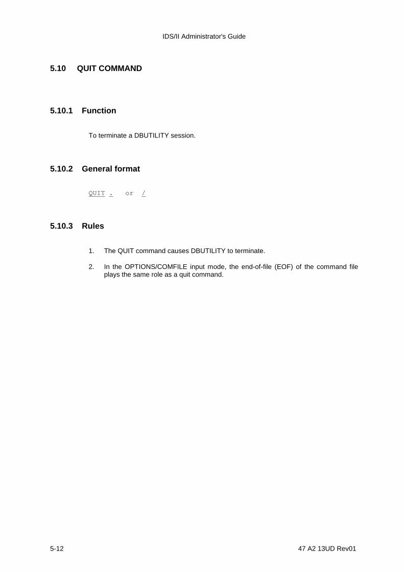
IDS/II Administrator's Guide
5-12 47 A2 13UD Rev01
5.10 QUIT COMMAND
5.10.1 Function
To terminate a DBUTILITY session.
5.10.2 General format
QUIT . or /
5.10.3 Rules
1. The QUIT command causes DBUTILITY to terminate.
2. In the OPTIONS/COMFILE input mode, the end-of-file (EOF) of the command fileplays the same role as a quit command.
47 A2 13UD Rev01 6-1
6. Database Print Functions
6.1 DBPRINT FUNCTIONS
The following database print functions are available:
1) First, you can print the contents of storage records.
For each record, the information which you can print out consists of:
- all or part of the fields, displayed in the schema format or in hexadecimal,- optionally, the set pointers, displayed in interpreted form,- optionally, the record header.
The types of record selection available are the following:- the area-key within a given area,- the CALC-key within a given area,- the participation in a set-type. Owners are selected by their area-key or their
CALC-key within a given area; members may be in any area.
2) Secondly, you can print the contents of area pages.
The information which you can print includes the page header, the locators, theCALC overflow links and the storage records. You must select pages by their pagenumbers within a given area.
3) Thirdly, you can print the contents of area or the contents of index labels.

IDS/II Administrator's Guide
6-2 47 A2 13UD Rev01
6.2 DBPRINT COMMAND LANGUAGE
6.2.1 Syntax Conventions
The syntax rules, reserved words and descriptive notations are those described in thepreface of this manual.
6.2.2 Types of Command
There are five commands described in the following subsections:
• the PRINT RECORD command with selection by area-key,
• the PRINT RECORD command with selection by CALC-key,
• the PRINT RECORD command with selection by set-participation,
• the PRINT PAGE command,
• the PRINT LABEL command.
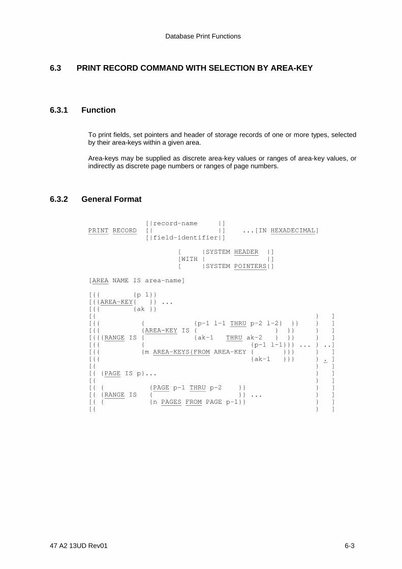
Database Print Functions
47 A2 13UD Rev01 6-3
6.3 PRINT RECORD COMMAND WITH SELECTION BY AREA-KEY
6.3.1 Function
To print fields, set pointers and header of storage records of one or more types, selectedby their area-keys within a given area.
Area-keys may be supplied as discrete area-key values or ranges of area-key values, orindirectly as discrete page numbers or ranges of page numbers.
6.3.2 General Format
[|record-name |]PRINT RECORD [| |] ...[IN HEXADECIMAL ] [|field-identifier|]
[ |SYSTEM HEADER |] [WITH | |] [ |SYSTEM POINTERS|]
[AREA NAME IS area-name]
[{{ {p l}}[{{AREA-KEY{ }} ...[{{ {ak }}[{ } ][{{ { {p-1 l-1 THRU p-2 l-2} }} } ][{{ {AREA-KEY IS { } }} } ][{{{RANGE IS { {ak-1 THRU ak-2 } }} } ][{{ { {p-1 l-1}}} ... } ..][{{ {m AREA-KEYS{FROM AREA-KEY { }}} } ][{{ {ak-1 }}} } . ][{ } ][{ {PAGE IS p}... } ][{ } ][{ { {PAGE p-1 THRU p-2 }} } ][{ {RANGE IS { }} ... } ][{ { {n PAGES FROM PAGE p-1}} } ][{ } ]
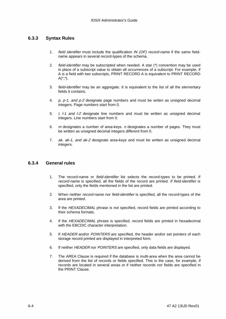
IDS/II Administrator's Guide
6-4 47 A2 13UD Rev01
6.3.3 Syntax Rules
1. field identifier must include the qualification IN (OF) record-name if the same field-name appears in several record-types of the schema.
2. field-identifier may be subscripted when needed. A star (*) convention may be usedin place of a subscript value to obtain all occurrences of a subscript. For example, ifA is a field with two subscripts, PRINT RECORD A is equivalent to PRINT RECORDA(*,*).
3. field-identifier may be an aggregate. It is equivalent to the list of all the elementaryfields it contains.
4. p, p-1, and p-2 designate page numbers and must be writen as unsigned decimalintegers. Page numbers start from 0.
5. l, l-1 and l-2 designate line numbers and must be written as unsigned decimalintegers. Line numbers start from 0.
6. m designates a number of area-keys. n designates a number of pages. They mustbe written as unsigned decimal integers different from 0.
7. ak, ak-1, and ak-2 designate area-keys and must be written as unsigned decimalintegers.
6.3.4 General rules
1. The record-name or field-identifier list selects the record-types to be printed. Ifrecord-name is specified, all the fields of the record are printed. If field-identifier isspecified, only the fields mentioned in the list are printed.
2. When neither record-name nor field-identifier is specified, all the record-types of thearea are printed.
3. If the HEXADECIMAL phrase is not specified, record fields are printed according totheir schema formats.
4. If the HEXADECIMAL phrase is specified, record fields are printed in hexadecimalwith the EBCDIC character interpretation.
5. If HEADER and/or POINTERS are specified, the header and/or set pointers of eachstorage record printed are displayed in interpreted form.
6. If neither HEADER nor POINTERS are specified, only data fields are displayed.
7. The AREA Clause is required if the database is multi-area when the area cannot bederived from the list of records or fields specified. This is the case, for example, ifrecords are located in several areas or if neither records nor fields are specified inthe PRINT Clause.

Database Print Functions
47 A2 13UD Rev01 6-5
8. The AREA-KEY, RANGE (AREA-KEY), PAGE and RANGE (PAGE) Clauses specifythe area-keys of the records to be printed.

IDS/II Administrator's Guide
6-6 47 A2 13UD Rev01
9. The AREA-KEY Clause specifies a discrete area-key. The area-key value may besupplied as either:
- a single integer value (ak), as specified by the DML for direct reference, as shownbelow:
area-key = (page-number * lines-per-page) + line-number
- or a pair of integer values (p l) which represent the following:
page-number line-number
10. The RANGE (AREA-KEY) Clause specifies a range of area-keys. The range isdefined as either:
- a first area-key and a last area-key. The values are inclusive. The first area-keyvalue must be less than or equal to the last area-key value.
- or, a number of area-keys starting from a given area-key. The range must fit intothe right-hand portion of the area. There is no possibility of wrap-around at the endof the area.
11. The PAGE Clause specifies a range composed of all the area-keys of the page.
12. The RANGE (PAGE) Clause specifies a range of pages. The range is defined aseither:
- the space between a first page number and a last page number. The values areinclusive. The first page number must be less than or equal to the last pagenumber.
- or, a group of pages starting from a given page number. The range must fit intothe right-hand portion of the area. There is no possibility of wrap-around at theend of the area.

Database Print Functions
47 A2 13UD Rev01 6-7
Figures 6-1 and 6-2 provide examples of reports produced by the PRINT RECORD (byarea-key) command, in SYSOUT and TERMINAL formats.
C: 109 109 PRINT RECORD W IN R02 HEADER POINTERS RANGE 2 AREA-KEYS FROM 1.COMMAND 3 **** PRINT RECORD COMMAND ****
**** SELECTED RECORD: R02 DBK:00000001 A:0 P:0 L:1 AN:A00 HEADER: STATE:ACTIVE CODE:2 SIZE:30 STATUS:0 NEXT CALC RECORD L:0 HASH CHECK:FFFF OWNER OWL RANK:0 POINTERS:OWNER OF SET02 L E N: 0001 A:- P:0 L:1 AN:A00 P: 0001 A:- P:0 L:1 AN:A00 MEMBER OF SET01 L N: 0000 A:- P:0 L:0 AN:A00 P: 0002 A:- P:0 L:2 AN:A00 O: 0000 A:- P:0 L:0 AN:A00
********************************************************************************************** *FIELD OFFSET: FIELD NAME (WITH SUBSCRIPT VALUES, IF ANY) : TYPE : FIELD CONTENTS * *------------+-------------------------------------------------+------+------------------* * 7 0007 : W(1) : CHAR : <> * * 9 0009 : W(2) : CHAR : >< * ********************************************************************************************** SELECTED RECORD: R02 DBK:00000002 A:0 P:0 L:2 AN:A00 HEADER: STATE:ACTIVE CODE:2 SIZE:30 STATUS:0 NEXT CALC RECORD L:1 HASH CHECK:03FF OWNER OWL RANK:0 POINTERS:OWNER OF SET02 L N: 0004 A:- P:0 L:4 AN:A00 P: 0003 A:- P:0 L:3 AN:A00 MEMBER OF SET01 L N: 0001 A:- P:0 L:1 AN:A00 P: 0000 A:- P:0 L:0 AN:A00 O: 0000 A:- P:0 L:0 AN:A00 ****************************************************************************************** *FIELD OFFSET: FIELD NAME (WITH SUBSCRIPT VALUES, IF ANY) : TYPE : FIELD CONTENTS * *------------+--------------------------------------------------+------+-----------------* * 7 0007 : W(1) : CHAR : () * * 9 0009 : W(2) : CHAR : )( * ******************************************************************************************
Figure 6-1. "PRINT RECORD" SYSOUT Report (Selection By Area-key)
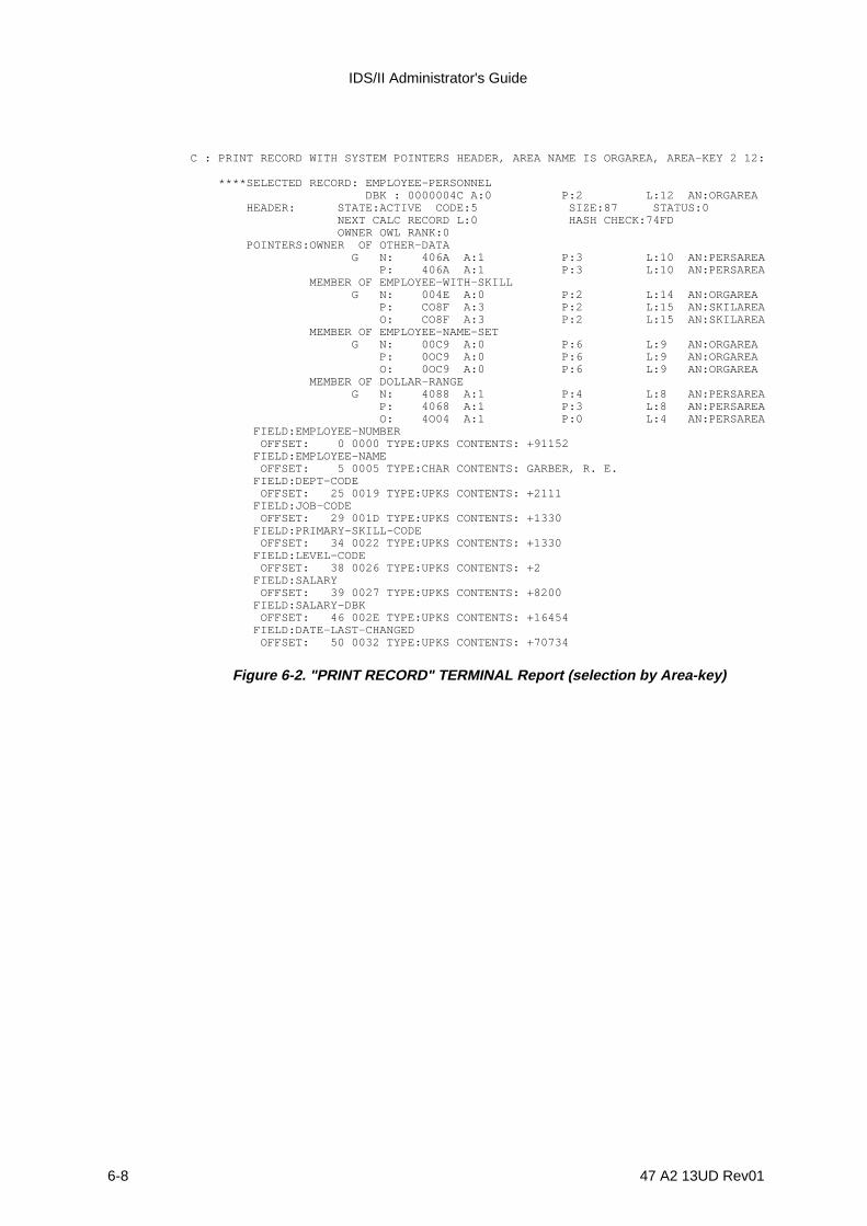
IDS/II Administrator's Guide
6-8 47 A2 13UD Rev01
C : PRINT RECORD WITH SYSTEM POINTERS HEADER, AREA NAME IS ORGAREA, AREA-KEY 2 12:
****SELECTED RECORD: EMPLOYEE-PERSONNEL DBK : 0000004C A:0 P:2 L:12 AN:ORGAREA HEADER: STATE:ACTIVE CODE:5 SIZE:87 STATUS:0 NEXT CALC RECORD L:0 HASH CHECK:74FD OWNER OWL RANK:0 POINTERS:OWNER OF OTHER-DATA G N: 406A A:1 P:3 L:10 AN:PERSAREA P: 406A A:1 P:3 L:10 AN:PERSAREA MEMBER OF EMPLOYEE-WITH-SKILL G N: 004E A:0 P:2 L:14 AN:ORGAREA P: CO8F A:3 P:2 L:15 AN:SKILAREA O: CO8F A:3 P:2 L:15 AN:SKILAREA MEMBER OF EMPLOYEE-NAME-SET G N: 00C9 A:0 P:6 L:9 AN:ORGAREA P: 0OC9 A:0 P:6 L:9 AN:ORGAREA O: 0OC9 A:0 P:6 L:9 AN:ORGAREA MEMBER OF DOLLAR-RANGE G N: 4088 A:1 P:4 L:8 AN:PERSAREA P: 4068 A:1 P:3 L:8 AN:PERSAREA O: 4O04 A:1 P:0 L:4 AN:PERSAREA FIELD:EMPLOYEE-NUMBER OFFSET: 0 0000 TYPE:UPKS CONTENTS: +91152 FIELD:EMPLOYEE-NAME OFFSET: 5 0005 TYPE:CHAR CONTENTS: GARBER, R. E. FIELD:DEPT-CODE OFFSET: 25 0019 TYPE:UPKS CONTENTS: +2111 FIELD:JOB-CODE OFFSET: 29 001D TYPE:UPKS CONTENTS: +1330 FIELD:PRIMARY-SKILL-CODE OFFSET: 34 0022 TYPE:UPKS CONTENTS: +1330 FIELD:LEVEL-CODE OFFSET: 38 0026 TYPE:UPKS CONTENTS: +2 FIELD:SALARY OFFSET: 39 0027 TYPE:UPKS CONTENTS: +8200 FIELD:SALARY-DBK OFFSET: 46 002E TYPE:UPKS CONTENTS: +16454 FIELD:DATE-LAST-CHANGED OFFSET: 50 0032 TYPE:UPKS CONTENTS: +70734
Figure 6-2. "PRINT RECORD" TERMINAL Report (selection by Area-key)

Database Print Functions
47 A2 13UD Rev01 6-9
6.4 PRINT RECORD COMMAND WITH SELECTION BY CALC-KEY
6.4.1 Function
To print the fields, set pointers and headers of CALC storage records of a given type,selected by their CALC-key values, within a given area.
6.4.2 General Format
{record-name }PRINT RECORD { } [IN HEXADECIMAL ] { {field-identifier} ...}
[ |SYSTEM HEADER |] [WITH | |] [ |SYSTEM POINTERS|]
[AREA NAME IS area-name]
{CALC-KEY IS {field-type-literal} ... } ... .
6.4.3 Syntax Rules
1. field-identifier obeys the same rules as those of the PRINT RECORD command withselection by area-key.
2. The record-type identified by record-type or field-identifier must have a CALClocation mode.
3. field-type-literal must conform to the rules for the comparison of data-base-identifiersand literals, as specified in Figure 1-2 of the Full IDS/II Reference Manual Volume I.
If the type of a CALC-key item is CHARACTER, field-type-literal is a character stringliteral or a hexadecimal string literal.
If the type of a CALC-key item is DECIMAL or BINARY, field-type-literal is a decimalnumber literal.
4. If the CALC-key is multi-item, the same number of literals as key items must besupplied. In addition the order according to which you supply them must be the sameas that specified in the LOCATION CALC Clause of the schema.

IDS/II Administrator's Guide
6-10 47 A2 13UD Rev01
6.4.4 General Rules
1. The various elements of the PRINT Clause have the same meaning as in the PRINTRECORD command with selection by area-key.
2. The AREA Clause must be specified if the CALC record-type is multi-area.
3. The CALC-KEY Clause specifies the CALC-key value of the record to be printed.

Database Print Functions
47 A2 13UD Rev01 6-11
6.5 PRINT RECORD COMMAND WITH SELECTION BY SET-PARTICIPATION
6.5.1 Function
To print fields, set pointers and headers of storage records participating in a set-type. Theowners of the set occurrences are selected by their area-keys or their CALC-key (ifapplicable) within a given area. Members may be in any area.
6.5.2 General Format
[|record-name |]PRINT RECORD [| |] ... [IN HEXADECIMAL ] [|field-identifier |]
[ | SYSTEM HEADER |] [ WITH| SYSTEM POINTERS |] WITHIN set-name [ | NUMBER-OF-MEMBERS |]
[ OWNER AREA NAME IS area-name ]
[ { { {p l}} }][ { {AREA-KEY { }} ... }][ { { {ak }} }][ { }][ { { { {p-1 l-1THRU p-2 l-2} }} }][ { { {AREA-KEY IS { } }} }][ { { { {ak THRU ak-2 } }} }][ { {RANGE IS{ {p-1 l-1} }} ... }][ OWNER { { {m AREA-KEYS FROM AREA-KEY { } }} }][ { { { {ak-1 } }} }][ }][ { {PAGE IS p} ... }][ { { {PAGE p-1THRU p-2 }} }][ { {RANGE IS{ }} ... }][ { { {nPAGES FROM PAGE p-1}} }][ { {CALC-KEY IS {field-type-literal }... }... }] [ WHEN MINIMUM NUMBER-OF-MEMBERS IS integer-1 ]
[ WHEN MAXIMUM NUMBER-OF-MEMBERS IS integer-2 ] .
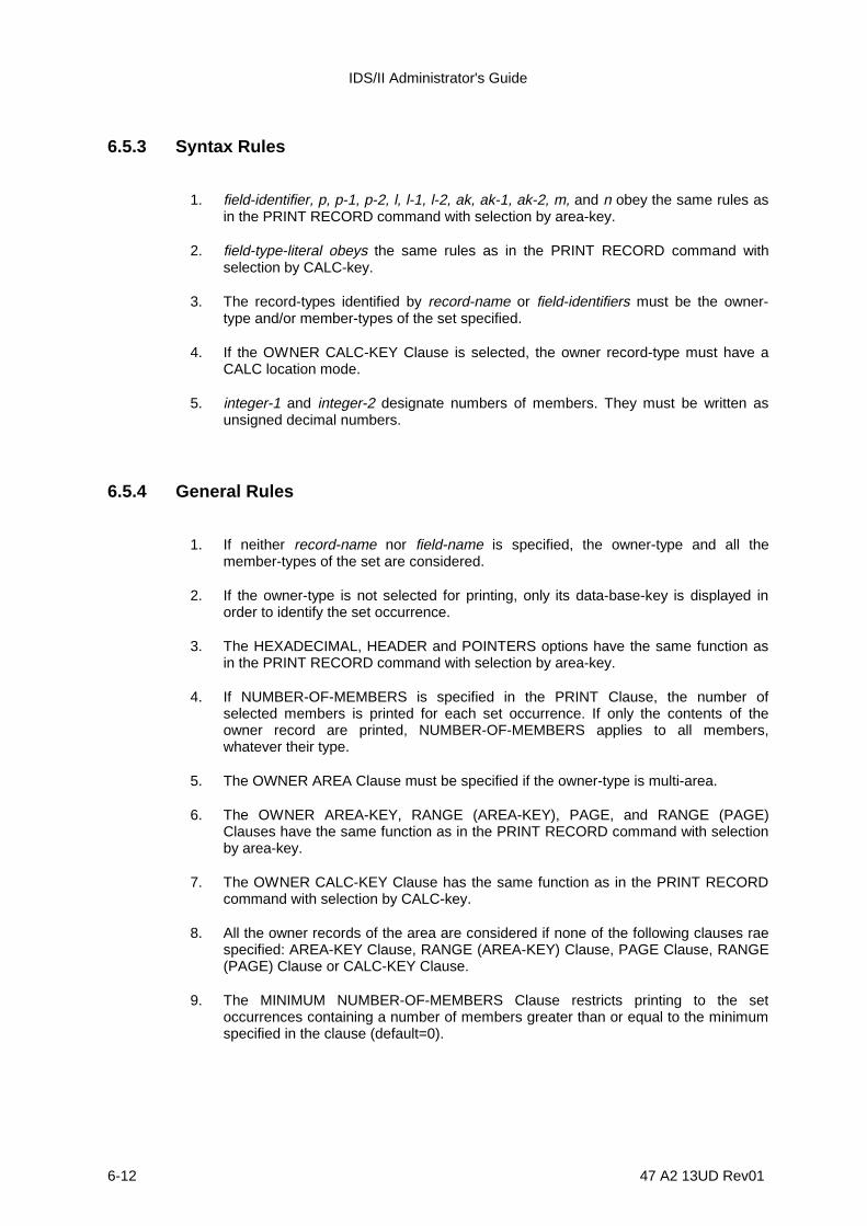
IDS/II Administrator's Guide
6-12 47 A2 13UD Rev01
6.5.3 Syntax Rules
1. field-identifier, p, p-1, p-2, l, l-1, l-2, ak, ak-1, ak-2, m, and n obey the same rules asin the PRINT RECORD command with selection by area-key.
2. field-type-literal obeys the same rules as in the PRINT RECORD command withselection by CALC-key.
3. The record-types identified by record-name or field-identifiers must be the owner-type and/or member-types of the set specified.
4. If the OWNER CALC-KEY Clause is selected, the owner record-type must have aCALC location mode.
5. integer-1 and integer-2 designate numbers of members. They must be written asunsigned decimal numbers.
6.5.4 General Rules
1. If neither record-name nor field-name is specified, the owner-type and all themember-types of the set are considered.
2. If the owner-type is not selected for printing, only its data-base-key is displayed inorder to identify the set occurrence.
3. The HEXADECIMAL, HEADER and POINTERS options have the same function asin the PRINT RECORD command with selection by area-key.
4. If NUMBER-OF-MEMBERS is specified in the PRINT Clause, the number ofselected members is printed for each set occurrence. If only the contents of theowner record are printed, NUMBER-OF-MEMBERS applies to all members,whatever their type.
5. The OWNER AREA Clause must be specified if the owner-type is multi-area.
6. The OWNER AREA-KEY, RANGE (AREA-KEY), PAGE, and RANGE (PAGE)Clauses have the same function as in the PRINT RECORD command with selectionby area-key.
7. The OWNER CALC-KEY Clause has the same function as in the PRINT RECORDcommand with selection by CALC-key.
8. All the owner records of the area are considered if none of the following clauses raespecified: AREA-KEY Clause, RANGE (AREA-KEY) Clause, PAGE Clause, RANGE(PAGE) Clause or CALC-KEY Clause.
9. The MINIMUM NUMBER-OF-MEMBERS Clause restricts printing to the setoccurrences containing a number of members greater than or equal to the minimumspecified in the clause (default=0).
Database Print Functions
47 A2 13UD Rev01 6-13
10. The MAXIMUM NUMBER-OF-MEMBERS Clause restricts printing to the setoccurrences containing a number of members less than or equal to a specifiedmaximum (default=infinite).

IDS/II Administrator's Guide
6-14 47 A2 13UD Rev01
11. MINIMUM and MAXIMUM refer to the following:
- the number of members of the specified types when the PRINT Clauseidentifies one or more member record-types.
- the number of members of all types when only the contents of the owner recordare to be printed.
Figures 6-3 and 6-4 provide reports produced by the PRINT RECORD command withselection by set-participation, in SYSOUT and TERMINAL formats.
C: 222 222 PRINT RECORD F11NUM HEADER POINTERS NUMBER-OF-MEMBERS WITHIN SET10-: 223 223 CALC-KEY "NAME10".COMMAND 2 **** PRINT RECORD COMMAND ****
**** SELECTED OWNER: R10 DBK:00004018 A:1 P:8 L:0 AN:A01 * SELECTED MEMBER: R11 DBK:0000401B A:1 P:9 L:0 AN:A01 HEADER: STATE:ACTIVE CODE:6 SIZE:19 STATUS:0 POINTERS:MEMBER OF SET10 L N: 001A A:- P:8 L:2 AN:A01 P: 0018 A:- P:8 L:0 AN:A01 O: 0018 A:- P:8 L:0 AN:A01 ****************************************************************************************** *FIELD OFFSET: FIELD NAME (WITH SUBSCRIPT VALUES, IF ANY) : TYPE : FIELD CONTENTS * *------------+-----------------------------------------------+------+--------------------* * 6 0006 : F11NUM : FB15 : +311 * ****************************************************************************************** * SELECTED MEMBER: R11 DBK:0000401A A:1 P:8 L:2 AN:A01 HEADER: STATE:ACTIVE CODE:6 SIZE:19 STATUS:0 POINTERS:MEMBER OF SET10 L N: 0019 A:- P:8 L:1 AN:A01 P: 001B A:- P:9 L:0 AN:A01 O: 0018 A:- P:8 L:0 AN:A01 ****************************************************************************************** *FIELD OFFSET: FIELD NAME (WITH SUBSCRIPT VALUES, IF ANY) : TYPE : FIELD CONTENTS * *------------+------------------------------------------------+------+-------------------* * 6 0006 : F11NUM : FB15 : +211 * ****************************************************************************************** * SELECTED MEMBER: R11 DBK:00004019 A:1 P:8 L:1 AN:A01 HEADER: STATE:ACTIVE CODE:6 SIZE:19 STATUS:0 POINTERS:MEMBER OF SET10 L N: 0018 A:- P:8 L:0 AN:A01 P: 001A A:- P:8 L:2 AN:A01 O: 0018 A:- P:8 L:0 AN:A01 ****************************************************************************************** *FIELD OFFSET: FIELD NAME (WITH SUBSCRIPT VALUES, IF ANY) : TYPE : FIELD CONTENTS * *------------+------------------------------------------------+------+-------------------* * 6 0006 : F11NUM : FB15 : +111 * ****************************************************************************************** ** NUMBER OF SELECTED MEMBERS: 3
Figure 6-3. "PRINT RECORD" SYSOUT Report (Selection by Set Participation)

Database Print Functions
47 A2 13UD Rev01 6-15
C: PRINT RECORD, HEXA, WITHIN EMPLOYEE-FUNCTION, AREA ORGAREA, AREA-KEY 2 0: ****SELECTED OWNER: ORGANIZATION-UNIT DBK:00000040 A:0 P:2 L:0 AN:ORGAREA ************************************************************************* OFFSET ] RECORD CONTENTS (IN HEXADECIMAL) (IN EBCDIC) ------------]------------------------------------------------------------ 0 0000 ] E2EBE2E3 C5D4E240 C5D5C7C9 D5C5C5D9 SYSTEMS ENGINEER 16 0010 ] C9D5C740 C7D9D6E4 D7404040 40400000 ING GROUP 32 0020 ] 083EFIF0 F3FIF2F3 F4F5C6 0010312345F ************************************************************************* *SELECTED MEMBER: JOB-FUNCTION DBK:0000006F A:0 P:3 L:15 AN:ORGAREA ************************************************************************* OFFSET ] RECORD CONTENTS (IN HEXADECIMAL) (IN EBCDIC) ------------]------------------------------------------------------------ 0 0000 ] F0FIFIFI C0C7D9D6 E4D740D4 CID5CIC7 0111 (GROUP MANAG 16 0010 ] C5D94040 40404040 40F0F0F0 CIFOFODI ER 000A001 32 0020 ] F7F5F0F0 F0CO 75000( ************************************************************************* *SELECTED MEMBER: JOB-FUNCTION DBK:00000070 A:0 P:3 L:16 AN:ORGAREA ************************************************************************* OFFSET ] RECORD CONTENTS (IN HEXADECIMAL) (IN EBCDIC) ------------]------------------------------------------------------------ 0 0000 ] F0F5F2F1 C0E2C5C3 D9C5E3CI D9E84040 0521 (SECRETARY 16 0010 ] 40404040 40404040 40F0F0F0 CIFOFOF0 000A000 32 0020 ] F4F2F0F0 F0CO 42000( *************************************************************************
Figure 6-4. "PRINT RECORD" TERMINAL Report (Selection by Set Participation)
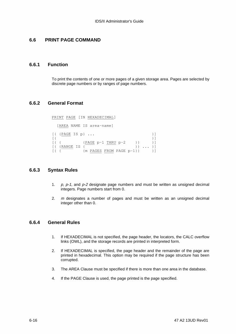
IDS/II Administrator's Guide
6-16 47 A2 13UD Rev01
6.6 PRINT PAGE COMMAND
6.6.1 Function
To print the contents of one or more pages of a given storage area. Pages are selected bydiscrete page numbers or by ranges of page numbers.
6.6.2 General Format
PRINT PAGE [IN HEXADECIMAL ]
[AREA NAME IS area-name]
[{ {PAGE IS p} ... }][{ }][{ { {PAGE p-1 THRU p-2 }} }][{ {RANGE IS { }} ... }][{ { {m PAGES FROM PAGE p-1}} }]
6.6.3 Syntax Rules
1. p, p-1, and p-2 designate page numbers and must be written as unsigned decimalintegers. Page numbers start from 0.
2. m designates a number of pages and must be written as an unsigned decimalinteger other than 0.
6.6.4 General Rules
1. If HEXADECIMAL is not specified, the page header, the locators, the CALC overflowlinks (OWL), and the storage records are printed in interpreted form.
2. If HEXADECIMAL is specified, the page header and the remainder of the page areprinted in hexadecimal. This option may be required if the page structure has beencorrupted.
3. The AREA Clause must be specified if there is more than one area in the database.
4. If the PAGE Clause is used, the page printed is the page specified.

Database Print Functions
47 A2 13UD Rev01 6-17
5. If the RANGE Clause is selected, the pages printed are those of the range specified.
The range is defined as either:
- The space between a first page number and a last page number. In this case, thevalues are inclusive. The first page number must be less than or equal to the lastpage number.
- A group of pages starting from a given page number. The range must fit into theright-hand portion of the area. There is no possibility of wrap-around at the end ofthe area.
6. If neither the PAGE Clause nor the RANGE Clause is specified, all the pages of thearea are printed.
Figures 6-5 and 6-6 provide reports produced by the PRINT PAGE command, without theHEXADECIMAL option, in SYSOUT and TERMINAL formats. Figure 6-7 provides a reportproduced by the PRINT PAGE command with the HEXADECIMAL option, in SYSOUTformat.
C: 24 24 PRINT PAGE PAGE IS 0;COMMAND 6 **** PRINT PAGE COMMAND ****
**** SELECTED PAGE: P:0 A:0 AN:A01DUTIL02 * HEADER: USED SPACE:56 FREE SPACE:471 CI:0 LOWEST AVAIL L:2 HIGHEST CURRENT L:1 * RECORD LOCATORS: LINE : 0 1 OFFSET: 000A 0019 * CALC OVERFLOW LINK (OWL): CURRENT OWL RANK:0 OFFSET:0000 FIRST CALC RECORD L:- NEXT OWL IN PAGE OFFSET:FFFF NEXT OWL IN CHAIN RANK:- P:- FIRST OWL IN CHAIN RANK:0 OFFSET:0000 P:0 * RECORD: R01DUTIL02 DBK:00000000 A:0 P:0 L:0 AN:A01DUTIL02 HEADER: STATE:ACTIVE CODE:1 SIZE:15 STATUS:0 ****************************************************************************************** *FIELD OFFSET: FIELD NAME (WITH SUBSCRIPT VALUES, IF ANY) : TYPE : FIELD CONTENTS * *------------+---------------------------------------------------+------+----------------* * 0 0000 : F01DUTIL02 : CHAR : ABCDE12345 * ****************************************************************************************** * RECORD: R01DUTIL02 DBK:00000001 A:0 P:0 L:1 AN:A01DUTIL02 HEADER: STATE:DELETED CODE:1 SIZE:15 STATUS:0 ****************************************************************************************** *FIELD OFFSET: FIELD NAME (WITH SUBSCRIPT VALUES, IF ANY) : TYPE : FIELD CONTENTS * *------------+---------------------------------------------------+------+----------------* * 0 0000 : F01DUTIL02 : CHAR : JKLMN06789 * ******************************************************************************************
Figure 6-5. PRINT PAGE" SYSOUT Report
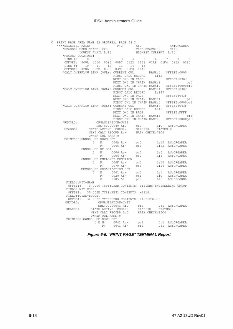
IDS/II Administrator's Guide
6-18 47 A2 13UD Rev01
C: PRINT PAGE AREA NAME IS ORGAREA, PAGE IS 2: ****SELECTED PAGE: P:2 A:0 AN:ORGAREA *HEADER: USED SPACE: 228 FREE SPACE:52 CI:2 LOWEST AVAIL L:16 HIGHEST CURRENT L:15 *RECORD LOCATORS: LINE #: 0 1 2 3 4 5 6 7 8 9 OFFSET: 000A 0050 0096 00DC 0122 0168 01AE 01F4 023A 0280 LINE #: 10 11 12 13 14 15 OFFSET: 0206 02FB 0330 0391 03E8 0449 *CALC OVERFLOW LINK (OWL): CURRENT OWL RANK:0 OFFSET:0000 FIRST CALC RECORD L:12 NEXT OWL IN PAGE OFFSET:0387 NEXT OWL IN CHAIN RANK:2 p:5 FIRST OWL IN CHAIN RANK:0 OFFSET:0000p:2 *CALC OVERFLOW LINK (OWL): CURRENT OWL RANK:1 OFFSET:0387 FIRST CALC RECORD L:147 NEXT OWL IN PAGE OFFSET:043F NEXT OWL IN CHAIN RANK:1 p:5 FIRST OWL IN CHAIN RANK:0 OFFSET:0000p:1 *CALC OVERFLOW LINK (OWL): CURRENT OWL RANK:2 OFFSET:043F FIRST CALC RECORD L:15 NEXT OWL IN PAGE OFFSET:FFFF NEXT OWL IN CHAIN RANK:3 p:5 FIRST OWL IN CHAIN RANK:0 OFFSET:0000p:0 *RECORD: ORGANIZATION-UNIT DBK:00000040 A:0 p:2 L:0 AN:ORGAREA HEADER: STATE:ACTIVE CODE:2 SIZE:70 STATUS:0 NEXT CALC RECORD L:- HASH CHECK:7BC6 OWNER OWL RANK:0 POINTERS:OWNER OF DOWN-SET L N: 006A A:- p:3 L:10 AN:ORGAREA P: 006C A:- p:3 L:12 AN:ORGAREA OWNER OF UP-SET L N: 0006 A:- p:0 L:6 AN:ORGAREA P: 0006 A:- p:0 L:6 AN:ORGAREA OWNER OF EMPLOYEE-FUNCTION L N: 006F A:- p:3 L:15 AN:ORGAREA P: 0070 A:- p:3 L:16 AN:ORGAREA MEMBER OF ORGANIZATION-SET L N: 0061 A:- p:3 L:1 AN:ORGAREA P: 0020 A:- p:1 L:0 AN:ORGAREA O: 0005 A:- p:0 L:5 AN:ORGAREA FIELD:UNIT-NAME OFFSET: 0 0000 TYPE:CHAR CONTENTS: SYSTEMS ENGINEERING GROUP FIELD:UNIT-CODE OFFSET: 30 00IE TYPE:FB31 CONTENTS: +2110 FIELD:TOTAL-BUDGET OFFSET: 34 0022 TYPE:UPKS CONTENTS: +1031234.56 *RECORD: ORGANIZATION-UNIT DBK:00000041 A:0 p:2 L:1 AN:ORGAREA HEADER: STATE:ACTIVE CODE:2 SIZE:70 STATUS:0 NEXT CALC RECORD L:0 HASH CHECK:BIC6 OWNER OWL RANK:0 POINTERS:OWNER OF DOWN-SET L E N: 0041 A:- p:2 L:1 AN:ORGAREA P: 0041 A:- p:2 L:1 AN:ORGAREA
Figure 6-6. "PRINT PAGE" TERMINAL Report
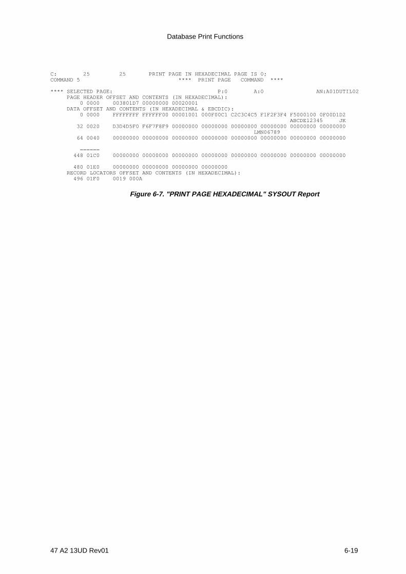
Database Print Functions
47 A2 13UD Rev01 6-19
C: 25 25 PRINT PAGE IN HEXADECIMAL PAGE IS 0;COMMAND 5 **** PRINT PAGE COMMAND ****
**** SELECTED PAGE: P:0 A:0 AN:A01DUTIL02 PAGE HEADER OFFSET AND CONTENTS (IN HEXADECIMAL): 0 0000 003801D7 00000000 00020001 DATA OFFSET AND CONTENTS (IN HEXADECIMAL & EBCDIC): 0 0000 FFFFFFFF FFFFFF00 00001001 000F00C1 C2C3C4C5 F1F2F3F4 F5000100 0F00D1D2 ABCDE12345 JK 32 0020 D3D4D5F0 F6F7F8F9 00000000 00000000 00000000 00000000 00000000 00000000 LMN06789 64 0040 00000000 00000000 00000000 00000000 00000000 00000000 00000000 00000000
====== 448 01C0 00000000 00000000 00000000 00000000 00000000 00000000 00000000 00000000
480 01E0 00000000 00000000 00000000 00000000 RECORD LOCATORS OFFSET AND CONTENTS (IN HEXADECIMAL): 496 01F0 0019 000A
Figure 6-7. "PRINT PAGE HEXADECIMAL" SYSOUT Report

IDS/II Administrator's Guide
6-20 47 A2 13UD Rev01
6.7 PRINT LABEL COMMAND
6.7.1 Function
To print the IDS/II label of one or more storage files (an area or an index file).
6.7.2 General Format
PRINT LABEL [IN HEXADECIMAL ]
[ { {AREA } } ][ { { } NAMES ARE {file-name} ... }... ] .[ { {INDEX} } ]
6.7.3 General Rules
1. If HEXADECIMAL is not specified, the IDS/II label is printed in interpreted form.
2. If HEXADECIMAL is specified, the IDS/II label is printed in hexadecimal form.
3. file-name must be specified if the database is multi-file.
Figure 6-8 provides a report produced by the PRINT LABEL AREA command in SYSOUTformat. Figure 6-9 provides a report of a PRINT LABEL INDEX command in SYSOUTformat.
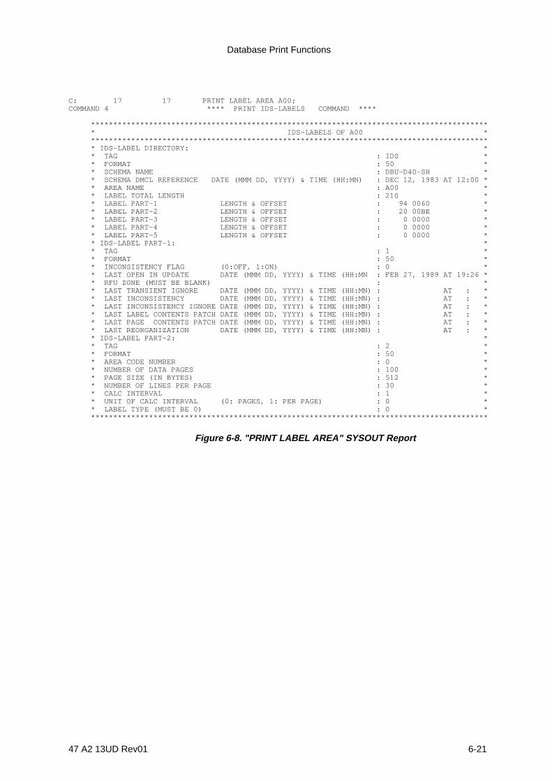
Database Print Functions
47 A2 13UD Rev01 6-21
C: 17 17 PRINT LABEL AREA A00;COMMAND 4 **** PRINT IDS-LABELS COMMAND ****
***************************************************************************************** * IDS-LABELS OF A00 * ***************************************************************************************** * IDS-LABEL DIRECTORY: * * TAG : IDS * * FORMAT : 50 * * SCHEMA NAME : DBU-D40-SH * * SCHEMA DMCL REFERENCE DATE (MMM DD, YYYY) & TIME (HH:MN) : DEC 12, 1983 AT 12:00 * * AREA NAME : A00 * * LABEL TOTAL LENGTH : 210 * * LABEL PART-1 LENGTH & OFFSET : 94 0060 * * LABEL PART-2 LENGTH & OFFSET : 20 00BE * * LABEL PART-3 LENGTH & OFFSET : 0 0000 * * LABEL PART-4 LENGTH & OFFSET : 0 0000 * * LABEL PART-5 LENGTH & OFFSET : 0 0000 * * IDS-LABEL PART-1: * * TAG : 1 * * FORMAT : 50 * * INCONSISTENCY FLAG (0:OFF, 1:ON) : 0 * * LAST OPEN IN UPDATE DATE (MMM DD, YYYY) & TIME (HH:MN : FEB 27, 1989 AT 19:26 * * RFU ZONE (MUST BE BLANK) : * * LAST TRANSIENT IGNORE DATE (MMM DD, YYYY) & TIME (HH:MN) : AT : * * LAST INCONSISTENCY DATE (MMM DD, YYYY) & TIME (HH:MN) : AT : * * LAST INCONSISTENCY IGNORE DATE (MMM DD, YYYY) & TIME (HH:MN) : AT : * * LAST LABEL CONTENTS PATCH DATE (MMM DD, YYYY) & TIME (HH:MN) : AT : * * LAST PAGE CONTENTS PATCH DATE (MMM DD, YYYY) & TIME (HH:MN) : AT : * * LAST REORGANIZATION DATE (MMM DD, YYYY) & TIME (HH:MN) : AT : * * IDS-LABEL PART-2: * * TAG : 2 * * FORMAT : 50 * * AREA CODE NUMBER : 0 * * NUMBER OF DATA PAGES : 100 * * PAGE SIZE (IN BYTES) : 512 * * NUMBER OF LINES PER PAGE : 30 * * CALC INTERVAL : 1 * * UNIT OF CALC INTERVAL (0: PAGES, 1: PER PAGE) : 0 * * LABEL TYPE (MUST BE 0) : 0 * *****************************************************************************************
Figure 6-8. "PRINT LABEL AREA" SYSOUT Report
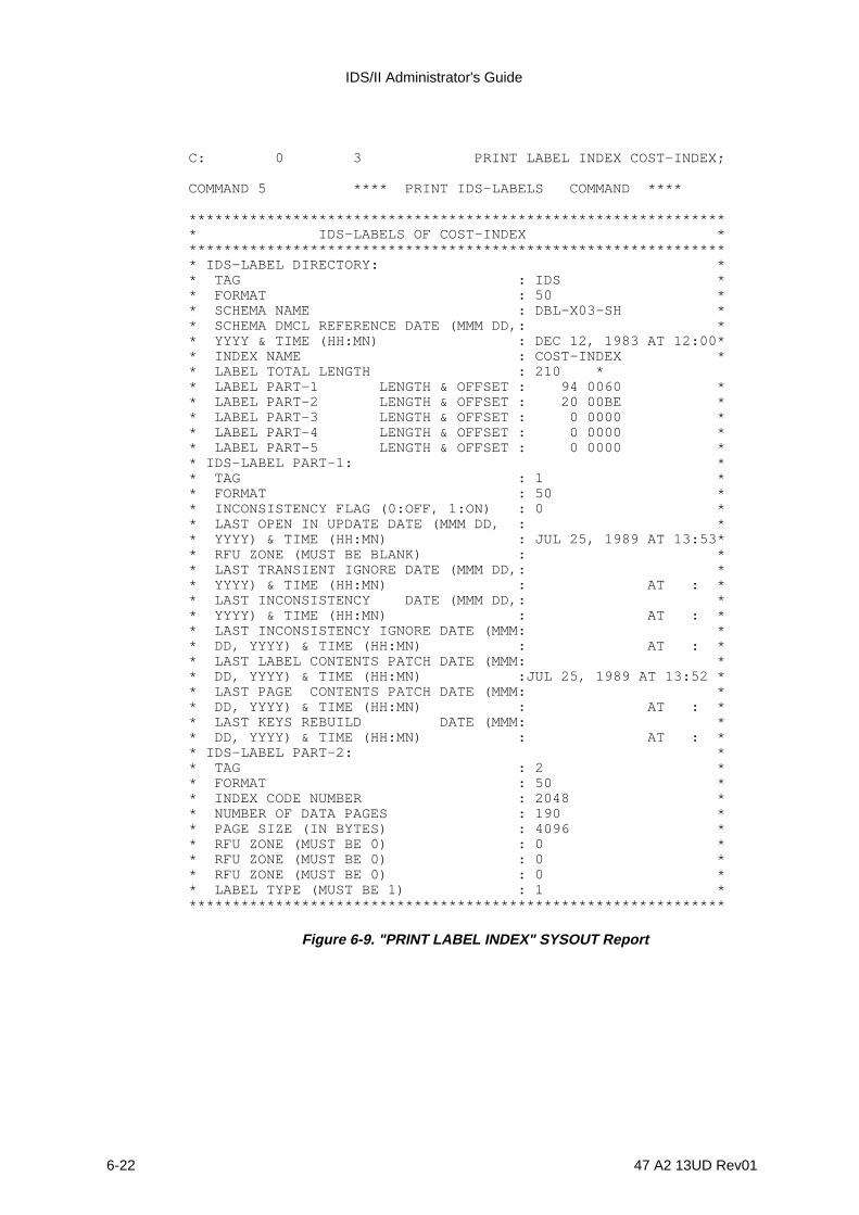
IDS/II Administrator's Guide
6-22 47 A2 13UD Rev01
C: 0 3 PRINT LABEL INDEX COST-INDEX;
COMMAND 5 **** PRINT IDS-LABELS COMMAND ****
*************************************************************** IDS-LABELS OF COST-INDEX **************************************************************** IDS-LABEL DIRECTORY: ** TAG : IDS ** FORMAT : 50 ** SCHEMA NAME : DBL-X03-SH ** SCHEMA DMCL REFERENCE DATE (MMM DD,: ** YYYY & TIME (HH:MN) : DEC 12, 1983 AT 12:00** INDEX NAME : COST-INDEX ** LABEL TOTAL LENGTH : 210 ** LABEL PART-1 LENGTH & OFFSET : 94 0060 ** LABEL PART-2 LENGTH & OFFSET : 20 00BE ** LABEL PART-3 LENGTH & OFFSET : 0 0000 ** LABEL PART-4 LENGTH & OFFSET : 0 0000 ** LABEL PART-5 LENGTH & OFFSET : 0 0000 ** IDS-LABEL PART-1: ** TAG : 1 ** FORMAT : 50 ** INCONSISTENCY FLAG (0:OFF, 1:ON) : 0 ** LAST OPEN IN UPDATE DATE (MMM DD, : ** YYYY) & TIME (HH:MN) : JUL 25, 1989 AT 13:53** RFU ZONE (MUST BE BLANK) : ** LAST TRANSIENT IGNORE DATE (MMM DD,: ** YYYY) & TIME (HH:MN) : AT : ** LAST INCONSISTENCY DATE (MMM DD,: ** YYYY) & TIME (HH:MN) : AT : ** LAST INCONSISTENCY IGNORE DATE (MMM: ** DD, YYYY) & TIME (HH:MN) : AT : ** LAST LABEL CONTENTS PATCH DATE (MMM: ** DD, YYYY) & TIME (HH:MN) :JUL 25, 1989 AT 13:52 ** LAST PAGE CONTENTS PATCH DATE (MMM: ** DD, YYYY) & TIME (HH:MN) : AT : ** LAST KEYS REBUILD DATE (MMM: ** DD, YYYY) & TIME (HH:MN) : AT : ** IDS-LABEL PART-2: ** TAG : 2 ** FORMAT : 50 ** INDEX CODE NUMBER : 2048 ** NUMBER OF DATA PAGES : 190 ** PAGE SIZE (IN BYTES) : 4096 ** RFU ZONE (MUST BE 0) : 0 ** RFU ZONE (MUST BE 0) : 0 ** RFU ZONE (MUST BE 0) : 0 ** LABEL TYPE (MUST BE 1) : 1 ***************************************************************
Figure 6-9. "PRINT LABEL INDEX" SYSOUT Report
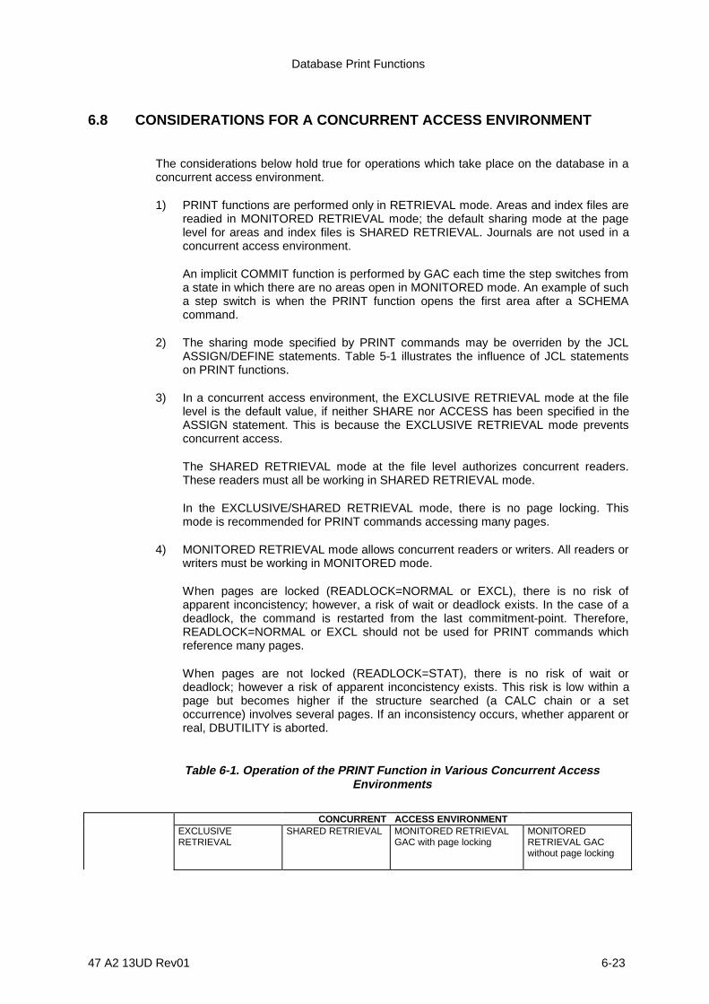
Database Print Functions
47 A2 13UD Rev01 6-23
6.8 CONSIDERATIONS FOR A CONCURRENT ACCESS ENVIRONMENT
The considerations below hold true for operations which take place on the database in aconcurrent access environment.
1) PRINT functions are performed only in RETRIEVAL mode. Areas and index files arereadied in MONITORED RETRIEVAL mode; the default sharing mode at the pagelevel for areas and index files is SHARED RETRIEVAL. Journals are not used in aconcurrent access environment.
An implicit COMMIT function is performed by GAC each time the step switches froma state in which there are no areas open in MONITORED mode. An example of sucha step switch is when the PRINT function opens the first area after a SCHEMAcommand.
2) The sharing mode specified by PRINT commands may be overriden by the JCLASSIGN/DEFINE statements. Table 5-1 illustrates the influence of JCL statementson PRINT functions.
3) In a concurrent access environment, the EXCLUSIVE RETRIEVAL mode at the filelevel is the default value, if neither SHARE nor ACCESS has been specified in theASSIGN statement. This is because the EXCLUSIVE RETRIEVAL mode preventsconcurrent access.
The SHARED RETRIEVAL mode at the file level authorizes concurrent readers.These readers must all be working in SHARED RETRIEVAL mode.
In the EXCLUSIVE/SHARED RETRIEVAL mode, there is no page locking. Thismode is recommended for PRINT commands accessing many pages.
4) MONITORED RETRIEVAL mode allows concurrent readers or writers. All readers orwriters must be working in MONITORED mode.
When pages are locked (READLOCK=NORMAL or EXCL), there is no risk ofapparent inconcistency; however, a risk of wait or deadlock exists. In the case of adeadlock, the command is restarted from the last commitment-point. Therefore,READLOCK=NORMAL or EXCL should not be used for PRINT commands whichreference many pages.
When pages are not locked (READLOCK=STAT), there is no risk of wait ordeadlock; however a risk of apparent inconcistency exists. This risk is low within apage but becomes higher if the structure searched (a CALC chain or a setoccurrence) involves several pages. If an inconsistency occurs, whether apparent orreal, DBUTILITY is aborted.
Table 6-1. Operation of the PRINT Function in Various Concurrent AccessEnvironments
CONCURRENT ACCESS ENVIRONMENTEXCLUSIVERETRIEVAL
SHARED RETRIEVAL MONITORED RETRIEVALGAC with page locking
MONITOREDRETRIEVAL GACwithout page locking
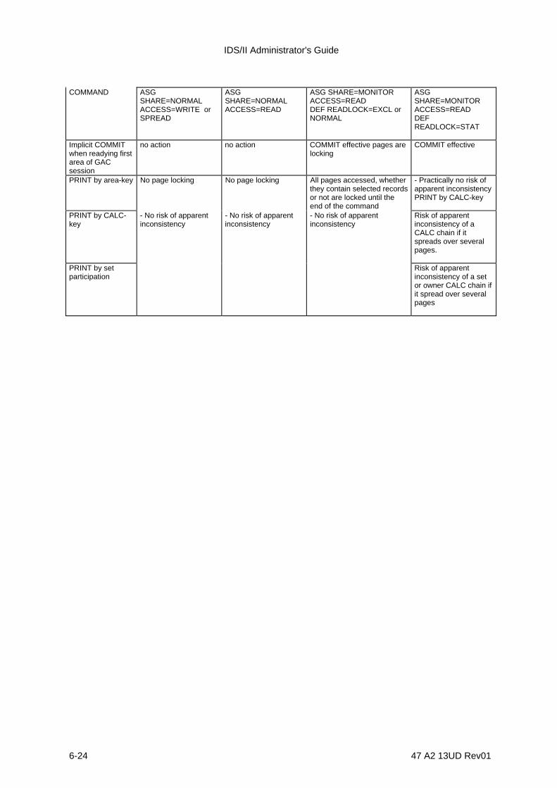
IDS/II Administrator's Guide
6-24 47 A2 13UD Rev01
COMMAND ASGSHARE=NORMALACCESS=WRITE orSPREAD
ASGSHARE=NORMALACCESS=READ
ASG SHARE=MONITORACCESS=READDEF READLOCK=EXCL orNORMAL
ASGSHARE=MONITORACCESS=READDEFREADLOCK=STAT
Implicit COMMITwhen readying firstarea of GACsession
no action no action COMMIT effective pages arelocking
COMMIT effective
PRINT by area-key No page locking No page locking All pages accessed, whetherthey contain selected recordsor not are locked until theend of the command
- Practically no risk ofapparent inconsistencyPRINT by CALC-key
PRINT by CALC-key
- No risk of apparentinconsistency
- No risk of apparentinconsistency
- No risk of apparentinconsistency
Risk of apparentinconsistency of aCALC chain if itspreads over severalpages.
PRINT by setparticipation
Risk of apparentinconsistency of a setor owner CALC chain ifit spread over severalpages
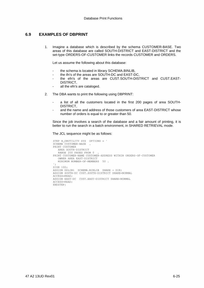
Database Print Functions
47 A2 13UD Rev01 6-25
6.9 EXAMPLES OF DBPRINT
1. Imagine a database which is described by the schema CUSTOMER-BASE. Twoareas of this database are called SOUTH-DISTRICT and EAST-DISTRICT and theset-type ORDERS-OF-CUSTOMER links the records CUSTOMER and ORDERS.
Let us assume the following about this database:
- the schema is located in library SCHEMA.BINLIB,- the ifn's of the areas are SOUTH-DC and EAST-DC,- the efn's of the areas are CUST.SOUTH-DISTRICT and CUST.EAST-
DISTRICT,- all the efn's are cataloged.
2. The DBA wants to print the following using DBPRINT:
- a list of all the customers located in the first 200 pages of area SOUTH-DISTRICT,
- and the name and address of those customers of area EAST-DISTRICT whosenumber of orders is equal to or greater than 50.
Since the job involves a search of the database and a fair amount of printing, it isbetter to run the search in a batch environment, in SHARED RETRIEVAL mode.
The JCL sequence might be as follows:
STEP H_DBUTILITY SYS OPTIONS = ' SCHEMA CUSTOMER-BASE . PRINT CUSTOMER AREA SOUTH-DISTRICT RANGE 200 PAGES FROM 0 . PRINT CUSTOMER-NAME CUSTOMER-ADDRESS WITHIN ORDERS-OF-CUSTOMER OWNER AREA EAST-DISTRICT MINIMUM NUMBER-OF-MEMBERS 50 . '; SIZE 100; ASSIGN DDLIB1 SCHEMA.BINLIB SHARE = DIR; ASSIGN SOUTH-DC CUST.SOUTH-DISTRICT SHARE=NORMAL ACCESS=READ; ASSIGN EAST-DC CUST.EAST-DISTRICT SHARE=NORMAL ACCESS=READ; ENDSTEP;

IDS/II Administrator's Guide
6-26 47 A2 13UD Rev01
3. The DBA now wants to print the orders of a specific customer from area SOUTH-DISTRICT. Since this involves a short search, DBUTILITY may be activated in anIOF environment in MONITORED RETRIEVAL mode. The records are printeddirectly at the terminal.
The terminal dialogue might be as follows:
S: STEP H_DBUTILITY SYS REPEAT; S: SIZE 100; S: ASG DDLIB1 SCHEMA.BINLIB SHARE=NORMAL ACCESS=READ; S: ASG SOUTH-DC CUST.SOUTH-DISTRICT SHARE=MONITOR ACCESS=READ; S: ENDSTEP; >>> 10:40 DBUTILITY 40.00 C: DISPLAY TERMINAL ; C: SCHEMA CUSTOMER-BASE ; START OF DDM SESSION ... LIBRARY NAME ... ... C: PRINT CUSTOMER ORDERS WITHIN ORDERS-OF-CUSTOMER -: OWNER AREA SOUTH-DISTRICT -: OWNER CALC "DUPONT" ; Record contents .... C: QUIT ; END OF DDM SESSION ... <<<
47 A2 13UD Rev01 7-1
7. Database Analysis Functions
7.1 DBANALYS FUNCTIONS
The database analysis functions of the DBANALYS Utility are outlined below:
1) DBANALYS provides a report of statistical information about storage areas in anexisting database. This report is provided in the form of a series of tables whichdescribe each area of the database. These tables provide summaries of thedistribution of used space, record distribution and the implementation of CALCchains.
2) DBANALYS provides a report of statistical information about existing index files. Thisreport is in the form of a series of tables on each index file corresponding to adatabase. These tables provide summaries of the distribution of used space and keydistribution.
3) DBANALYS performs a simulation of the loading of CALC records of one record-type(with or without members) and produces statistical information about the simulateddatabase. This function of DBANALYS provides a summary report concerning thedistribution of used space, record distribution, the implementation of CALC chainsand clusters.
4) DBANALYS sorts CALC records of one record-type in decreasing order of the pagenumber to which these records randomize. This sort is performed in order toaccelerate loading of these records.

IDS/II Administrator's Guide
7-2 47 A2 13UD Rev01
7.2 DBANALYS COMMAND LANGUAGE
7.2.1 Syntax Conventions
Syntax rules, reserved words and descriptive notations are described in the preface of thismanual.
7.2.2 Types of Command
There are four DBANALYS commands:
• ANALYSE AREA command• ANALYSE INDEX command• SIMULOAD command• SORT command
These commands are described in detail on the following subsections.
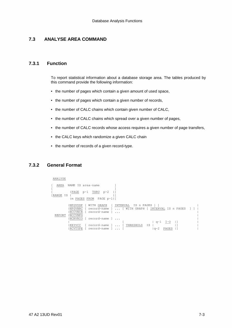
Database Analysis Functions
47 A2 13UD Rev01 7-3
7.3 ANALYSE AREA COMMAND
7.3.1 Function
To report statistical information about a database storage area. The tables produced bythis command provide the following information:
• the number of pages which contain a given amount of used space,
• the number of pages which contain a given number of records,
• the number of CALC chains which contain given number of CALC,
• the number of CALC chains which spread over a given number of pages,
• the number of CALC records whose access requires a given number of page transfers,
• the CALC keys which randomize a given CALC chain
• the number of records of a given record-type.
7.3.2 General Format
ANALYSE
[ AREA NAME IS area-name ][ ][ {PAGE p-1 THRU p-2 }][RANGE IS { }] {m PAGES FROM PAGE p-1}]
|NPGVUSP [ WITH GRAPH [ INTERVAL IS n PAGES ] ] | |NPGVNRC [ record-name ] ... [ WITH GRAPH [ INTERVAL IS n PAGES ] ] | |NCCVNCR [ record-name ] ... | REPORT |NCCVNPG | |NCRVNIO [ record-name ] ... | | [ | q-1 I-O |] | |KEYVCC [ record-name ] ... [ THRESHOLD IS | |] | |RCVTYPE [ record-name ] ... [ |q-2 PAGES |] |

IDS/II Administrator's Guide
7-4 47 A2 13UD Rev01
7.3.3 Syntax Rules
1. p-1 and p-2 designate page numbers and must be written as unsigned decimalintegers. Page numbers start from 0.
2. m and n designate numbers of pages and must be written as an unsigned decimalinteger other than 0.
3. q-1 and q-2 are unsigned decimal integers other than 0.
7.3.4 General Rules
1. The AREA Clause must be specified if the database is multi-area.
2. If the RANGE Clause is used, the analysis is restricted to the range specified.
The range is defined as either:
- The space between a first page number and a last page number. Values areinclusive. The first page number must be less than or equal to the last pagenumber,
- The group of pages starting from a specified page number. This range must fitinto the right-hand portion of the area. There is no possibility of wrap-around atthe end of the area.
If the analysis involves CALC chains, the first page of the range must be the firstpage of a CALC bucket.
3. If the RANGE Clause is omitted, the entire area is analyzed.
4. The relative percentages reported in the tables refer to the total number of pages ofthe range specified (or of the area, if RANGE is not specified).
If the analysis involves only one record-type, it is recommended that the largest sizewhich you specify should be equal to the DMCL range of this record-type. Otherwisepages that cannot contain records of this type will distort the percentages.
5. The REPORT Clause specifies the type of information to be produced in the report.No table entry is printed for variables which report a null value at the end of theanalysis.
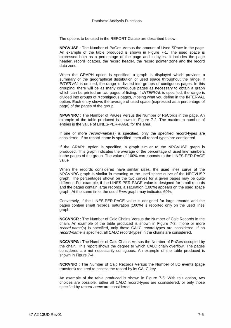
Database Analysis Functions
47 A2 13UD Rev01 7-5
The options to be used in the REPORT Clause are described below:
NPGVUSP : The Number of PaGes Versus the amount of Used SPace in the page.An example of the table produced is shown in Figure 7-1. The used space isexpressed both as a percentage of the page and in bytes. It includes the pageheader, record locators, the record header, the record pointer zone and the recorddata zone.
When the GRAPH option is specified, a graph is displayed which provides asummary of the geographical distribution of used space throughout the range. IfINTERVAL is omitted, the range is divided into groups of contiguous pages. In thisgrouping, there will be as many contiguous pages as necessary to obtain a graphwhich can be printed on two pages of listing. If INTERVAL is specified, the range isdivided into groups of n contiguous pages, n being what you define in the INTERVALoption. Each entry shows the average of used space (expressed as a percentage ofpage) of the pages of the group.
NPGVNRC : The Number of PaGes Versus the Number of ReCords in the page. Anexample of the table produced is shown in Figure 7-2. The maximum number ofentries is the value of LINES-PER-PAGE for the area.
If one or more record-name(s) is specified, only the specified record-types areconsidered. If no record-name is specified, then all record-types are considered.
If the GRAPH option is specified, a graph similar to the NPGVUSP graph isproduced. This graph indicates the average of the percentage of used line numbersin the pages of the group. The value of 100% corresponds to the LINES-PER-PAGEvalue
When the records considered have similar sizes, the used lines curve of theNPGVNRC graph is similar in meaning to the used space curve of the NPGVUSPgraph. The percentages shown on the two curves for a given pages may be quitedifferent. For example, if the LINES-PER-PAGE value is designed for small recordsand the pages contain large records, a saturation (100%) appears on the used spacegraph. At the same time, the used lines graph may indicates 60%.
Conversely, if the LINES-PER-PAGE value is designed for large records and thepages contain small records, saturation (100%) is reported only on the used linesgraph.
NCCVNCR : The Number of Calc Chains Versus the Number of Calc Records in thechain. An example of the table produced is shown in Figure 7-3. If one or morerecord-name(s) is specified, only those CALC record-types are considered. If norecord-name is specified, all CALC record-types in the chains are considered.
NCCVNPG : The Number of Calc Chains Versus the Number of PaGes occupied bythe chain. This report shows the degree to which CALC chain overflow. The pagesconsidered are not necessarily contiguous. An example of the table produced isshown in Figure 7-4.
NCRVNIO : The Number of Calc Records Versus the Number of I/O events (pagetransfers) required to access the record by its CALC-key.
An example of the table produced is shown in Figure 7-5. With this option, twochoices are possible: Either all CALC record-types are cconsidered, or only thosespecified by record-name are considered.

IDS/II Administrator's Guide
7-6 47 A2 13UD Rev01
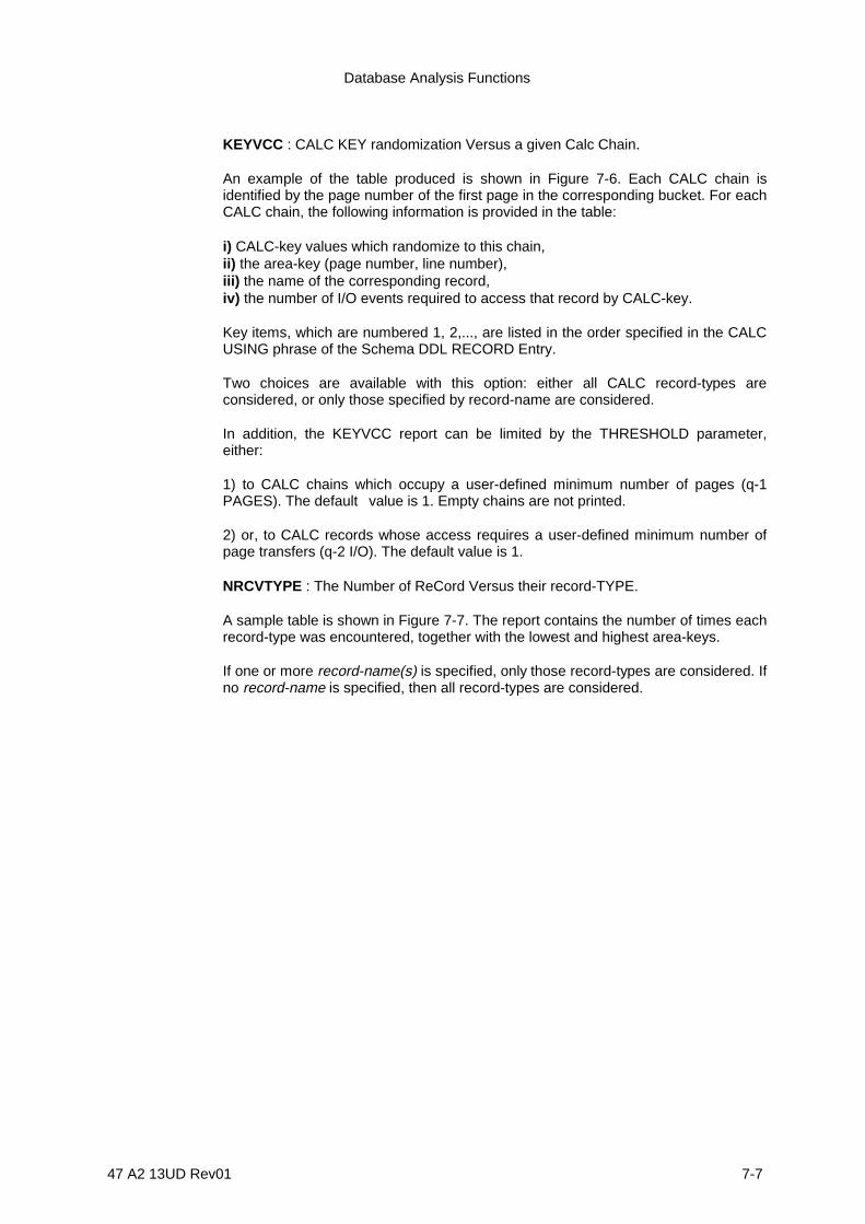
Database Analysis Functions
47 A2 13UD Rev01 7-7
KEYVCC : CALC KEY randomization Versus a given Calc Chain.
An example of the table produced is shown in Figure 7-6. Each CALC chain isidentified by the page number of the first page in the corresponding bucket. For eachCALC chain, the following information is provided in the table:
i) CALC-key values which randomize to this chain,ii) the area-key (page number, line number),iii) the name of the corresponding record,iv) the number of I/O events required to access that record by CALC-key.
Key items, which are numbered 1, 2,..., are listed in the order specified in the CALCUSING phrase of the Schema DDL RECORD Entry.
Two choices are available with this option: either all CALC record-types areconsidered, or only those specified by record-name are considered.
In addition, the KEYVCC report can be limited by the THRESHOLD parameter,either:
1) to CALC chains which occupy a user-defined minimum number of pages (q-1PAGES). The default value is 1. Empty chains are not printed.
2) or, to CALC records whose access requires a user-defined minimum number ofpage transfers (q-2 I/O). The default value is 1.
NRCVTYPE : The Number of ReCord Versus their record-TYPE.
A sample table is shown in Figure 7-7. The report contains the number of times eachrecord-type was encountered, together with the lowest and highest area-keys.
If one or more record-name(s) is specified, only those record-types are considered. Ifno record-name is specified, then all record-types are considered.

IDS/II Administrator's Guide
7-8 47 A2 13UD Rev01
COMMAND 2 **** ANALYZE COMMAND **** NPGVUSP : NUMBER OF PAGES VERSUS THE AMOUNT OF USED SPACE
************************************************************************************** * USED : USED : NUMBER : RELATIVE : INCREASING : DECREASING * * SPACE IN : SPACE IN : OF : % OF : CUMULATED % OF: CUMULATED % OF* * PAGE % : BYTES : PAGES : PAGES : PAGES : PAGES * *----------+-----------+--------------+--------------+----------------+--------------* * 0-5 : 0-25 : 30 : 49.18 : 49.18 : 50.82 * * 10-15 : 52-77 : 1 : 1.64 : 50.82 : 49.18 * * 15-20 : 78-103 : 23 : 37.7 : 88.52 : 11.48 * * 20-25 : 104-129 : 3 : 4.92 : 93.44 : 6.56 * * 25-30 : 130-155 : 4 : 6.56 : 100 : 0 * **************************************************************************************
COMMAND 3 **** ANALYZE COMMAND **** NPGVUSP : NUMBER OF PAGES VERSUS THE AMOUNT OF USED SPACE
**************************************** * DISTRIBUTION GRAPH * **************************************** PERCENTAGE OF USED SPACE ON CORRESPONDING GROUP OF PAGES PAGES :0 10 20 30 40 50 60 70 80 90 100 %-------------------+-------------------------------------------------------------------------> 0-0 :XXXXX : : : : : : : : : 1-1 :XXXXXXXXXXXXXXXXXXX : : : : : : : : 2-2 :XXXXXXXXXXXXXXXXXXX : : : : : : : : 3-3 :XXXXXXXXXXXXXXXXXXX : : : : : : : : 4-4 :XXXXXXXXXXXXXXXXXXX : : : : : : : : 5-5 :XXXXXXXXXXXXXXXXXXX : : : : : : : : 6-6 :XXXXXXXXXXXXXXXXXXX : : : : : : : : 7-7 :XXXXXXXXXXXXXXXXXXXXXXXXXXX : : : : : : : 8-8 :XXXXXXXXXXXXXXXXXXXXXXXXXXX : : : : : : : 9-9 :XXXXXXXXXXXXXXXXXXXXXXXXX : : : : : : : 10-10 :XXXXXXXXXXXXXXXXXXX : : : : : : : : 11-11 :XXXXXXXXXXXXXXXXXXX : : : : : : : : 12-12 :XXXXX : : : : : : : : : 13-13 :XXXXX : : : : : : : : : 14-14 :XXXXX : : : : : : : : : 15-15 :XXXXX : : : : : : : : : 16-16 :XXXXX : : : : : : : : : 17-17 :XXXXXXXXXXXXXXXX : : : : : : : : 18-18 :XXXXX : : : : : : : : : 19-19 :XXXXX : : : : : : : : : 20-20 :XXXXX : : : : : : : : : 21-21 :XXXXX : : : : : : : : : 22-22 :XXXXXXXXXXXXXXXXXX : : : : : : : : 23-23 :XXXXXXXXXXXXXXXXXX : : : : : : : : 24-24 :XXXXXXXXXXXXXXXXXX : : : : : : : : 25-25 :XXXXXXXXXXXXXXXXXX : : : : : : : : 26-26 :XXXXX : : : : : : : : : 27-27 :XXXXXXXXXXXXXXXXXX : : : : : : : : 28-28 :XXXXXXXXXXXXXXXXXX : : : : : : : : 29-29 :XXXXXXXXXXXXXXXXXX : : : : : : : : 30-30 :XXXXXXXXXXXXXXXXXX : : : : : : : : 31-31 :XXXXXXXXXXXXXXXXXX : : : : : : : : 32-32 :XXXXXXXXXXXXXXXXXX : : : : : : : : 33-33 :XXXXXXXXXXXXXXXXXXXXXX : : : : : : : 34-34 :XXXXXXXXXXXXXXXXXX : : : : : : : : 35-35 :XXXXXXXXXXXXXXXXXX : : : : : : : : 36-36 :XXXXXXXXXXXXXXXXXX : : : : : : : : 37-37 :XXXXXXXXXXXXXXXXXXXX: : : : : : : : 38-38 :XXXXXXXXXXXXXXXXXXXXX : : : : : : : 39-39 :XXXXXXXXXXXXXXXXXXXXXXXXXX : : : : : : : 40-40 :XXXXXXXXXXXXXXXXXXXXXXXXXXXXXXX : : : : : : 41-41 :XXXXXXXXXXXXXXXXXXXXXXXXXXXXX : : : : : : : 42-42 :XXXXX : : : : : : : : :
Figure 7-1. ANALYSE "Number of Pages Versus Used Space" Report sand Graph(1/2)

Database Analysis Functions
47 A2 13UD Rev01 7-9
43-43 :XXXXX : : : : : : : : : 44-44 :XXXXX : : : : : : : : : 45-45 :XXXXX : : : : : : : : : 46-46 :XXXXX : : : : : : : : : 47-47 :XXXXX : : : : : : : : : 48-48 :XXXXX : : : : : : : : : 49-49 :XXXXX : : : : : : : : : 50-50 :XXXXX : : : : : : : : : 51-51 :XXXXX : : : : : : : : : 52-52 :XXXXX : : : : : : : : : 53-53 :XXXXX : : : : : : : : : 54-54 :XXXXX : : : : : : : : : 55-55 :XXXXX : : : : : : : : : 56-56 :XXXXX : : : : : : : : : 57-57 :XXXXX : : : : : : : : : 58-58 :XXXXX : : : : : : : : : 59-59 :XXXXX : : : : : : : : : 60-60 :XXXXX : : : : : : : : : : V
Figure 7-1. ANALYSE "Number of Pages Versus Used Space" Report sand Graph(2/2)

IDS/II Administrator's Guide
7-10 47 A2 13UD Rev01
COMMAND 8 **** ANALYZE COMMAND **** NPGVNRC : NUMBER OF PAGES VERSUS NUMBER OF RECORDS IN PAGE
**************************************************************************** * NUMBER : NUMBER : RELATIVE : INCREASING : DECREASING * * OF : OF : % OF : CUMULATED % OF : CUMULATED % OF * * RECORDS : PAGES : PAGES : PAGES : PAGES * *------------+------------+--------------+----------------+----------------* * 0 : 26 : 70.27 : 70.27 : 29.73 * * 1 : 1 : 2.7 : 72.97 : 27.03 * * 2 : 1 : 2.7 : 75.68 : 24.32 * * 4 : 3 : 8.11 : 83.78 : 16.22 * * 5 : 1 : 2.7 : 86.49 : 13.51 * * 10 : 1 : 2.7 : 89.19 : 10.81 * * 11 : 1 : 2.7 : 91.89 : 8.11 * * 12 : 1 : 2.7 : 94.59 : 5.41 * * 13 : 2 : 5.41 : 100 : 0 * ****************************************************************************
COMMAND 1 **** ANALYZE COMMAND **** NPGVNRC : NUMBER OF PAGES VERSUS NUMBER OF RECORDS IN PAGE
**************************************** * DISTRIBUTION GRAPH * **************************************** PERCENTAGE OF USED LINES ON CORRESPONDING GROUP OF PAGES PAGES :0 10 20 30 40 50 60 70 80 90 100 %-------------------+-------------------------------------------------------------------------> 0-0 :XXXXXXXXX : : : : : : : : 1-1 :X : : : : : : : : 2-2 :X : : : : : : : : 3-3 :X : : : : : : : : 4-4 :X : : : : : : : : 5-5 :X : : : : : : : : 6-6 :XXXXXXXXXXXXXXXXXXXXXXXXXXXXXXXXXXXXXXXXXXXXXXXXXXXXXXXXXXXXXXXXX: : 7-7 :XXXXXXXXXXXXXXXXXXXXXXXXXXXXXXXXXXXXXXX : : : : : 8-8 :X : : : : : : : : 9-9 :X : : : : : : : : 10-10 :XXXXXXXXXXXXXXXX : : : : : : : 11-11 :XXXXXXXXXXXXXXXXXXXXXXXXXXXXXXXX : : : : : 12-12 :XXXXXXXXXXXXXXXXXXXXXXXXXXXXXXXXXXXXXXXXXXXXXXXXXXXXXXXXXXXXXXXXX: : 13-13 :XXXXXXXXXXXXXXXXXXXXXXXXXXXXXXXXXXXXXXXXXXXXXXXXXXXXXXXXXXXXXXXXX: : 14-14 :X : : : : : : : : 15-15 :XXXXXXXXXXXXXXXXXXXXXXXXXXXXXXXXXXXXXXXXXXXXXXXXXXXXXXXXXXXXXXXXX: : 16-16 :XXXXXXXXXXXXXXXXXXXXXXXXXXXXXXXXXXXXXXXXXXXXXXXXXXXXXXXXXXXXXXXXX: : 17-17 :XXXXXXXXXXXXXXXXXXXXXXXXXXXXXXXX : : : : : 18-18 :X : : : : : : : : 19-19 :X : : : : : : : : 20-20 :XXXXXXXXXXXXXXXXXXXXXXXXXXXXXXXX : : : : : 21-21 :X : : : : : : : : 22-22 :X : : : : : : : : 23-23 :X : : : : : : : : 24-24 :X : : : : : : : : 25-25 :X : : : : : : : : 26-26 :X : : : : : : : : 27-27 :X : : : : : : : : : V
Figure 7-2. ANALYSE "Number of Pages Versus Number of Records" Report andGrapth
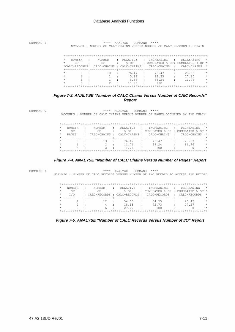
Database Analysis Functions
47 A2 13UD Rev01 7-11
COMMAND 1 **** ANALYZE COMMAND **** NCCVNCR : NUMBER OF CALC CHAINS VERSUS NUMBER OF CALC RECORDS IN CHAIN
**************************************************************************** * NUMBER : NUMBER : RELATIVE : INCREASING : DECREASING * * OF : OF : % OF : CUMULATED % OF: CUMULATED % OF * *CALC-RECORDS: CALC-CHAINS : CALC-CHAINS : CALC-CHAINS : CALC-CHAINS * *------------+--------------+-------------+---------------+----------------* * 0 : 13 : 76.47 : 76.47 : 23.53 * * 1 : 1 : 5.88 : 82.35 : 17.65 * * 3 : 1 : 5.88 : 88.24 : 11.76 * * 9 : 2 : 11.76 : 100 : 0 * ****************************************************************************
Figure 7-3. ANALYSE "Number of CALC Chains Versus Number of CAlC Records"Report
COMMAND 9 **** ANALYZE COMMAND **** NCCVNPG : NUMBER OF CALC CHAINS VERSUS NUMBER OF PAGES OCCUPIED BY THE CHAIN
****************************************************************************** * NUMBER : NUMBER : RELATIVE : INCREASING : DECREASING * * OF : OF : % OF : CUMULATED % OF : CUMULATED % OF * * PAGES : CALC-CHAINS : CALC-CHAINS : CALC-CHAINS : CALC-CHAINS * *------------+--------------+--------------+----------------+----------------* * 0 : 13 : 76.47 : 76.47 : 23.53 * * 1 : 2 : 11.76 : 88.24 : 11.76 * * 3 : 2 : 11.76 : 100 : 0 * ******************************************************************************
Figure 7-4. ANALYSE "Number of CALC Chains Versus Number of Pages" Report
COMMAND 7 **** ANALYZE COMMAND **** NCRVNIO : NUMBER OF CALC RECORDS VERSUS NUMBER OF I/O NEEDED TO ACCESS THE RECORD
****************************************************************************** * NUMBER : NUMBER : RELATIVE : INCREASING : DECREASING * * OF : OF : % OF : CUMULATED % OF : CUMULATED % OF * * I/O : CALC-RECORDS : CALC-RECORDS : CALC-RECORDS : CALC-RECORDS * *------------+--------------+--------------+----------------+----------------* * 1 : 12 : 54.55 : 54.55 : 45.45 * * 2 : 4 : 18.18 : 72.73 : 27.27 * * 3 : 6 : 27.27 : 100 : 0 * ******************************************************************************
Figure 7-5. ANALYSE "Number of CALC Records Versus Number of I/O" Report

IDS/II Administrator's Guide
7-12 47 A2 13UD Rev01
COMMAND 3 **** ANALYZE COMMAND **** KEYVCC : CALC KEYS RANDOMIZATION VERSUS A GIVEN CALC CHAIN
***********************************************************************************************CALC-INT.: : : KEY : : NUMBER** FIRST : AREA-KEY : CALC RECORD NAME :ITEM : CALC KEY VALUE : OF ** PAGE : : : : : I/O **---------+-------------+--------------------------------+-----+---------------------+-------** 0 : 0-0 : R05 : 1 : -7821 : 1 ** 2 : 2-2 : R01 : 1 : +45 : 1 ** 2 : 2-1 : R01 : 1 : +0 : 1 ** 2 : 2-0 : R01 : 1 : +9 : 1 ** 7 : 7-3 : R01 : 1 : +479 : 1 ** 7 : 7-2 : R01 : 1 : +479 : 1 ** 7 : 7-1 : R01 : 1 : +98 : 1 ** 7 : 7-0 : R01 : 1 : -26789 : 1 ** 7 : 14-3 : R01 : 1 : +479 : 2 ** 7 : 15-3 : R01 : 1 : +479 : 3 ** 7 : 15-2 : R01 : 1 : +479 : 3 ** 7 : 15-1 : R01 : 1 : +479 : 3 ** 7 : 15-0 : R01 : 1 : +479 : 3 ** 12 : 12-3 : R01 : 1 : +670 : 1 ** 12 : 12-2 : R01 : 1 : -4566 : 1 ** 12 : 12-1 : R01 : 1 : +1234 : 1 ** 12 : 12-0 : R01 : 1 : -6 : 1 ** 12 : 13-2 : R01 : 1 : -6 : 2 ** 12 : 13-1 : R05 : 1 : +11221 : 2 ** 12 : 13-0 : R01 : 1 : +9004 : 2 ** 12 : 14-2 : R05 : 1 : +11221 : 3 ** 12 : 14-0 : R01 : 1 : -6 : 3 ***********************************************************************************************
Figure 7-6. ANALYSE CALC-keys Versus CALC Chains" Report
NRCVTYPE : NUMBER OF RECORDS VERSUS CORRESPONDING RECORD NAMES
********************************************************************* : : : ** : NUMBER : LOWEST : HIGHEST ** RECORD NAME : OF : AREA-KEY : AREA-KEY ** : RECORDS : VALUE : VALUE **----------------------:------------:-------------:----------------** SKILL-CLASS : 26 : 0-0 : 5-11 ** SKILL : 71 : 0-14 : 9-6 ** SUB-SKILL : 13 : 3-8 : 8-13 ** TOOLS : 10 : 0-15 : 7-10 ** NUTS-AND-BOLTS : 15 : 5-38 : 7-16 ** FORMS : 14 : 5-29 : 7-8 *********************************************************************
Figure 7-7. ANALYSE "Number of records Versus their record-type" Report
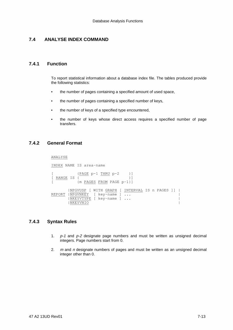
Database Analysis Functions
47 A2 13UD Rev01 7-13
7.4 ANALYSE INDEX COMMAND
7.4.1 Function
To report statistical information about a database index file. The tables produced providethe following statistics:
• the number of pages containing a specified amount of used space,
• the number of pages containing a specified number of keys,
• the number of keys of a specified type encountered,
• the number of keys whose direct access requires a specified number of pagetransfers.
7.4.2 General Format
ANALYSE
INDEX NAME IS area-name
[ {PAGE p-1 THRU p-2 }][ RANGE IS { }][ {m PAGES FROM PAGE p-1}]
|NPGVUSP [ WITH GRAPH [ INTERVAL IS n PAGES ]] |REPORT |NPGVNKEY [ key-name ] ... | |NKEYVTYPE [ key-name ] ... | |NKEYVNIO |
7.4.3 Syntax Rules
1. p-1 and p-2 designate page numbers and must be written as unsigned decimalintegers. Page numbers start from 0.
2. m and n designate numbers of pages and must be written as an unsigned decimalinteger other than 0.
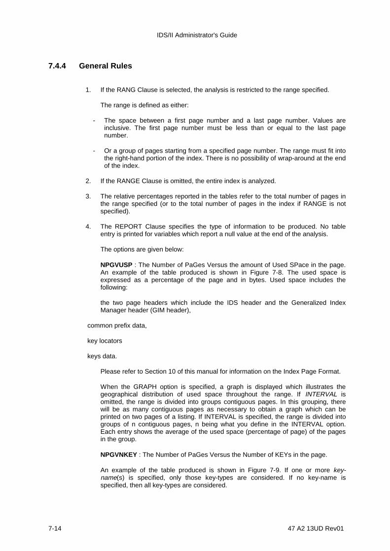
IDS/II Administrator's Guide
7-14 47 A2 13UD Rev01
7.4.4 General Rules
1. If the RANG Clause is selected, the analysis is restricted to the range specified.
The range is defined as either:
- The space between a first page number and a last page number. Values areinclusive. The first page number must be less than or equal to the last pagenumber.
- Or a group of pages starting from a specified page number. The range must fit intothe right-hand portion of the index. There is no possibility of wrap-around at the endof the index.
2. If the RANGE Clause is omitted, the entire index is analyzed.
3. The relative percentages reported in the tables refer to the total number of pages inthe range specified (or to the total number of pages in the index if RANGE is notspecified).
4. The REPORT Clause specifies the type of information to be produced. No tableentry is printed for variables which report a null value at the end of the analysis.
The options are given below:
NPGVUSP : The Number of PaGes Versus the amount of Used SPace in the page.An example of the table produced is shown in Figure 7-8. The used space isexpressed as a percentage of the page and in bytes. Used space includes thefollowing:
the two page headers which include the IDS header and the Generalized IndexManager header (GIM header),
common prefix data,
key locators
keys data.
Please refer to Section 10 of this manual for information on the Index Page Format.
When the GRAPH option is specified, a graph is displayed which illustrates thegeographical distribution of used space throughout the range. If INTERVAL isomitted, the range is divided into groups contiguous pages. In this grouping, therewill be as many contiguous pages as necessary to obtain a graph which can beprinted on two pages of a listing. If INTERVAL is specified, the range is divided intogroups of n contiguous pages, n being what you define in the INTERVAL option.Each entry shows the average of the used space (percentage of page) of the pagesin the group.
NPGVNKEY : The Number of PaGes Versus the Number of KEYs in the page.
An example of the table produced is shown in Figure 7-9. If one or more key-name(s) is specified, only those key-types are considered. If no key-name isspecified, then all key-types are considered.

Database Analysis Functions
47 A2 13UD Rev01 7-15
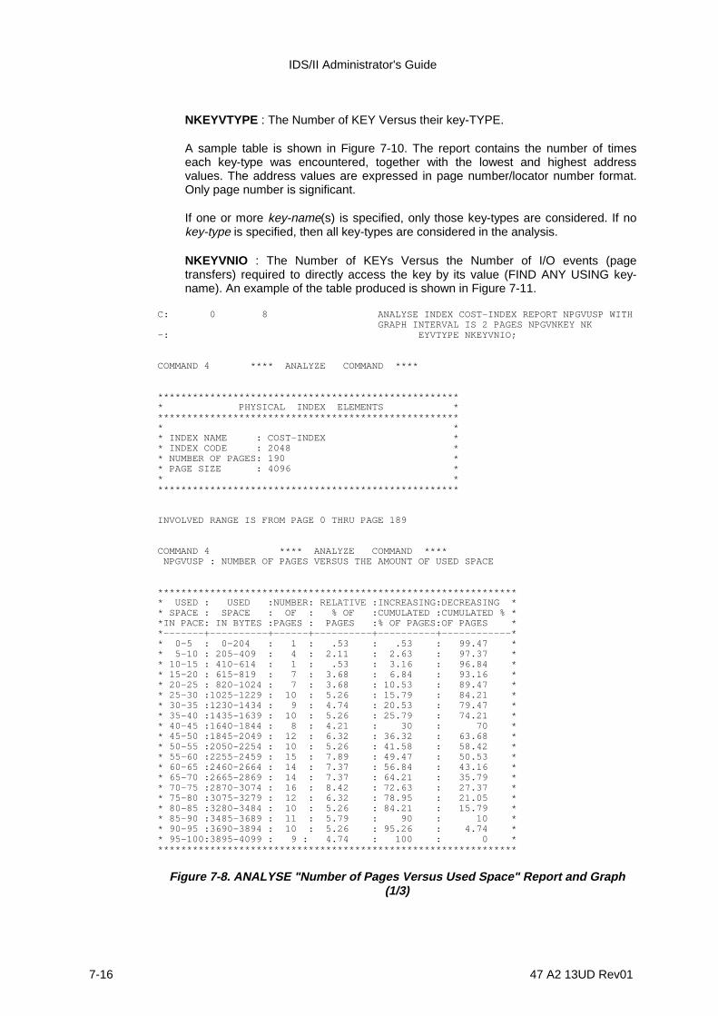
IDS/II Administrator's Guide
7-16 47 A2 13UD Rev01
NKEYVTYPE : The Number of KEY Versus their key-TYPE.
A sample table is shown in Figure 7-10. The report contains the number of timeseach key-type was encountered, together with the lowest and highest addressvalues. The address values are expressed in page number/locator number format.Only page number is significant.
If one or more key-name(s) is specified, only those key-types are considered. If nokey-type is specified, then all key-types are considered in the analysis.
NKEYVNIO : The Number of KEYs Versus the Number of I/O events (pagetransfers) required to directly access the key by its value (FIND ANY USING key-name). An example of the table produced is shown in Figure 7-11.
C: 0 8 ANALYSE INDEX COST-INDEX REPORT NPGVUSP WITH GRAPH INTERVAL IS 2 PAGES NPGVNKEY NK-: EYVTYPE NKEYVNIO;
COMMAND 4 **** ANALYZE COMMAND ****
***************************************************** PHYSICAL INDEX ELEMENTS ****************************************************** ** INDEX NAME : COST-INDEX ** INDEX CODE : 2048 ** NUMBER OF PAGES: 190 ** PAGE SIZE : 4096 ** *****************************************************
INVOLVED RANGE IS FROM PAGE 0 THRU PAGE 189
COMMAND 4 **** ANALYZE COMMAND **** NPGVUSP : NUMBER OF PAGES VERSUS THE AMOUNT OF USED SPACE
*************************************************************** USED : USED :NUMBER: RELATIVE :INCREASING:DECREASING ** SPACE : SPACE : OF : % OF :CUMULATED :CUMULATED % **IN PACE: IN BYTES :PAGES : PAGES :% OF PAGES:OF PAGES **-------+----------+------+----------+----------+------------** 0-5 : 0-204 : 1 : .53 : .53 : 99.47 ** 5-10 : 205-409 : 4 : 2.11 : 2.63 : 97.37 ** 10-15 : 410-614 : 1 : .53 : 3.16 : 96.84 ** 15-20 : 615-819 : 7 : 3.68 : 6.84 : 93.16 ** 20-25 : 820-1024 : 7 : 3.68 : 10.53 : 89.47 ** 25-30 :1025-1229 : 10 : 5.26 : 15.79 : 84.21 ** 30-35 :1230-1434 : 9 : 4.74 : 20.53 : 79.47 ** 35-40 :1435-1639 : 10 : 5.26 : 25.79 : 74.21 ** 40-45 :1640-1844 : 8 : 4.21 : 30 : 70 ** 45-50 :1845-2049 : 12 : 6.32 : 36.32 : 63.68 ** 50-55 :2050-2254 : 10 : 5.26 : 41.58 : 58.42 ** 55-60 :2255-2459 : 15 : 7.89 : 49.47 : 50.53 ** 60-65 :2460-2664 : 14 : 7.37 : 56.84 : 43.16 ** 65-70 :2665-2869 : 14 : 7.37 : 64.21 : 35.79 ** 70-75 :2870-3074 : 16 : 8.42 : 72.63 : 27.37 ** 75-80 :3075-3279 : 12 : 6.32 : 78.95 : 21.05 ** 80-85 :3280-3484 : 10 : 5.26 : 84.21 : 15.79 ** 85-90 :3485-3689 : 11 : 5.79 : 90 : 10 ** 90-95 :3690-3894 : 10 : 5.26 : 95.26 : 4.74 ** 95-100:3895-4099 : 9 : 4.74 : 100 : 0 ***************************************************************
Figure 7-8. ANALYSE "Number of Pages Versus Used Space" Report and Graph(1/3)
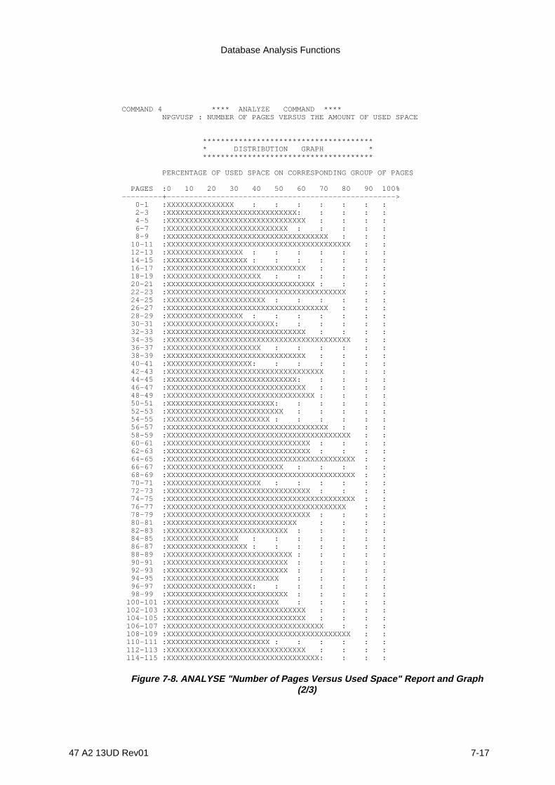
Database Analysis Functions
47 A2 13UD Rev01 7-17
COMMAND 4 **** ANALYZE COMMAND **** NPGVUSP : NUMBER OF PAGES VERSUS THE AMOUNT OF USED SPACE
************************************** * DISTRIBUTION GRAPH * **************************************
PERCENTAGE OF USED SPACE ON CORRESPONDING GROUP OF PAGES
PAGES :0 10 20 30 40 50 60 70 80 90 100%---------+---------------------------------------------------> 0-1 :XXXXXXXXXXXXXXX : : : : : : : 2-3 :XXXXXXXXXXXXXXXXXXXXXXXXXXXXX: : : : : 4-5 :XXXXXXXXXXXXXXXXXXXXXXXXXXXXXXX : : : : 6-7 :XXXXXXXXXXXXXXXXXXXXXXXXXXX : : : : : 8-9 :XXXXXXXXXXXXXXXXXXXXXXXXXXXXXXXXXXXX : : : 10-11 :XXXXXXXXXXXXXXXXXXXXXXXXXXXXXXXXXXXXXXXXX : : 12-13 :XXXXXXXXXXXXXXXXX : : : : : : : 14-15 :XXXXXXXXXXXXXXXXXX : : : : : : : 16-17 :XXXXXXXXXXXXXXXXXXXXXXXXXXXXXXX : : : : 18-19 :XXXXXXXXXXXXXXXXXXXXX : : : : : : 20-21 :XXXXXXXXXXXXXXXXXXXXXXXXXXXXXXXXX : : : : 22-23 :XXXXXXXXXXXXXXXXXXXXXXXXXXXXXXXXXXXXXXXX : : 24-25 :XXXXXXXXXXXXXXXXXXXXXX : : : : : : 26-27 :XXXXXXXXXXXXXXXXXXXXXXXXXXXXXXXXXXXX : : : 28-29 :XXXXXXXXXXXXXXXXX : : : : : : : 30-31 :XXXXXXXXXXXXXXXXXXXXXXXX: : : : : : 32-33 :XXXXXXXXXXXXXXXXXXXXXXXXXXXXXXX : : : : 34-35 :XXXXXXXXXXXXXXXXXXXXXXXXXXXXXXXXXXXXXXXXX : : 36-37 :XXXXXXXXXXXXXXXXXXXXX : : : : : : 38-39 :XXXXXXXXXXXXXXXXXXXXXXXXXXXXXXX : : : : 40-41 :XXXXXXXXXXXXXXXXXXX: : : : : : : 42-43 :XXXXXXXXXXXXXXXXXXXXXXXXXXXXXXXXXXX : : : 44-45 :XXXXXXXXXXXXXXXXXXXXXXXXXXXXX: : : : : 46-47 :XXXXXXXXXXXXXXXXXXXXXXXXXXXXXXX : : : : 48-49 :XXXXXXXXXXXXXXXXXXXXXXXXXXXXXXXXX : : : : 50-51 :XXXXXXXXXXXXXXXXXXXXXXXX: : : : : : 52-53 :XXXXXXXXXXXXXXXXXXXXXXXXXX : : : : : 54-55 :XXXXXXXXXXXXXXXXXXXXXXX : : : : : : 56-57 :XXXXXXXXXXXXXXXXXXXXXXXXXXXXXXXXXXXX : : : 58-59 :XXXXXXXXXXXXXXXXXXXXXXXXXXXXXXXXXXXXXXXXX : : 60-61 :XXXXXXXXXXXXXXXXXXXXXXXXXXXXXXXX : : : : 62-63 :XXXXXXXXXXXXXXXXXXXXXXXXXXXXXXXX : : : : 64-65 :XXXXXXXXXXXXXXXXXXXXXXXXXXXXXXXXXXXXXXXXXX : : 66-67 :XXXXXXXXXXXXXXXXXXXXXXXXXX : : : : : 68-69 :XXXXXXXXXXXXXXXXXXXXXXXXXXXXXXXXXXXXXXXXXX : : 70-71 :XXXXXXXXXXXXXXXXXXXXX : : : : : : 72-73 :XXXXXXXXXXXXXXXXXXXXXXXXXXXXXXXX : : : : 74-75 :XXXXXXXXXXXXXXXXXXXXXXXXXXXXXXXXXXXXXXXXXX : : 76-77 :XXXXXXXXXXXXXXXXXXXXXXXXXXXXXXXXXXXXXXXX : : 78-79 :XXXXXXXXXXXXXXXXXXXXXXXXXXXXXXXX : : : : 80-81 :XXXXXXXXXXXXXXXXXXXXXXXXXXXXX : : : : 82-83 :XXXXXXXXXXXXXXXXXXXXXXXXXXX : : : : : 84-85 :XXXXXXXXXXXXXXXX : : : : : : : 86-87 :XXXXXXXXXXXXXXXXXX : : : : : : : 88-89 :XXXXXXXXXXXXXXXXXXXXXXXXXXXX : : : : : 90-91 :XXXXXXXXXXXXXXXXXXXXXXXXXXX : : : : : 92-93 :XXXXXXXXXXXXXXXXXXXXXXXXXXX : : : : : 94-95 :XXXXXXXXXXXXXXXXXXXXXXXXX : : : : : 96-97 :XXXXXXXXXXXXXXXXXXX: : : : : : : 98-99 :XXXXXXXXXXXXXXXXXXXXXXXXXXX : : : : : 100-101 :XXXXXXXXXXXXXXXXXXXXXXXXX : : : : : 102-103 :XXXXXXXXXXXXXXXXXXXXXXXXXXXXXXX : : : : 104-105 :XXXXXXXXXXXXXXXXXXXXXXXXXXXXXXX : : : : 106-107 :XXXXXXXXXXXXXXXXXXXXXXXXXXXXXXXXXXX : : : 108-109 :XXXXXXXXXXXXXXXXXXXXXXXXXXXXXXXXXXXXXXXXX : : 110-111 :XXXXXXXXXXXXXXXXXXXXXXX : : : : : : 112-113 :XXXXXXXXXXXXXXXXXXXXXXXXXXXXXXX : : : : 114-115 :XXXXXXXXXXXXXXXXXXXXXXXXXXXXXXXXXX: : : :
Figure 7-8. ANALYSE "Number of Pages Versus Used Space" Report and Graph(2/3)

IDS/II Administrator's Guide
7-18 47 A2 13UD Rev01
116-117 :XXXXXXXXXXXXXXXXXXXXXXXXXXXXXXXX : : : : 118-119 :XXXXXXXXXXXXXXXXXXXXXXXXXXXXXXX : : : : 120-121 :XXXXXXXXXXXXXXXXXXXXXXXXXXXXXXXXX : : : : 122-123 :XXXXXXXXXXXXXXXXXXX: : : : : : : 124-125 :XXXXXXXXXXXXXXXXXXXXXXXXXXXXXXXXXXXXXXXXXXXXXX : 126-127 :XXXXXXXXXXXXXXXXXXXXXXXXXXXXXX : : : : 128-129 :XXXXXXXXXXXXXXXXXXXXXXX : : : : : : 130-131 :XXXXXXXXXXXXXXXXXXXXXXXXX : : : : : 132-133 :XXXXXXXXXXXXXXXXXXXXXXXXXXX : : : : : 134-135 :XXXXXXXXXXXXXXXXXXXXXXX : : : : : 136-137 :XXXXXXXXXXXXXXXXXXXXXXXXXXXXXX : : : : 138-139 :XXXXXXXXXXXXXXXXXXXXXXXXXXXXXXX : : : : 140-141 :XXXXXXXXXXXXXXXXXXXXXXXXXXXXXX : : : : 142-143 :XXXXXXXXXXXXXXXXXXXXXXXXXXXXXXXX : : : : 144-145 :XXXXXXXXXXXXXXXXXXXXXXXXXXXXXXXXXXXXXXXXXXXXXX : 146-147 :XXXXXXXXXXXXXXXXXXXXXXXXXXXXXXXXXX: : : : 148-149 :XXXXXXXXXXXXXXXXXX : : : : : : : 150-151 :XXXXXXXXXXXXXXXXXXXXXXXXXXXXXXXXXXXXXXXXXX : : 152-153 :XXXXXXXXXXXXXXXXXXXXXXXXXXXXXXXXXXXXXXXXX : : 154-155 :XXXXXXXXXXXXXXXXXXXXXXXXXXX : : : : : 156-157 :XXXXXXXXXXXXXXXXXXXXXXXXXXXXXXXXXXXX : : : 158-159 :XXXXXXXXXXXXXXXXXXXXXXXXXXXXXXXXXXXX : : : 160-161 :XXXXXXXXXXXXXXXXXXXXXXXXXX : : : : : 162-163 :XXXXXXXXXXXXXXXXX : : : : : : : 164-165 :XXXXXXXXXXXXXXXXXXXXXXXXXXXXXXXXXXXXX : : : 166-167 :XXXXXXXXXXXXXXXXX : : : : : : : 168-169 :XXXXXXXXXXXXXXXXXXXXXXXXXXXXXXX : : : : 170-171 :XXXXXXXXXXXXXXXXXXXXXXXXXXX : : : : : 172-173 :XXXXXXXXXXXXXXXXXXXXXXXXXXXXXXX : : : : 174-175 :XXXXXXXXXXXXXXXXXXXXXXXXX : : : : : 176-177 :XXXXXXXXXXXXXXXXXXXXXXXXXXXXXXXXXXX : : : 178-179 :XXXXXXXXXXXXXXXXXXXXXXXXX : : : : : 180-181 :XXXXXXXXXXXXXXXXXXXXXXXXXXXXXXXXXXXXXXXXX : : 182-183 :XXXXXXXXXXXXXXXXXXXXXXXXX : : : : : 184-185 :XXXXXXXXXXXXXXXXXX : : : : : : : 186-187 :XXXXXXXXXXXXXXXXXXXXXXXXXX : : : : : 188-189 :XXXXXXXXXXXX : : : : : : : : : V
Figure 7-8. ANALYSE "Number of Pages Versus Used Space" Report and Graph(3/3)

Database Analysis Functions
47 A2 13UD Rev01 7-19
COMMAND 4 **** ANALYZE COMMAND **** NPGVNKEY : NUMBER OF PAGES VERSUS NUMBER OF KEYS IN PAGE
*************************************************************** NUMBER : NUMBER : RELATIVE : INCREASING : DECREASING ** OF : OF : % OF :CUMULATED % OF: CUMULATED % OF ** KEYS : PAGES : PAGES : PAGES : PAGES **--------+--------+----------+--------------+----------------** : 1 : .53 : .53 : 99.47 ** 10 : 2 : 1.05 : 1.58 : 98.42 ** 11 : 1 : .53 : 2.11 : 97.89 ** 13 : 1 : .53 : 2.63 : 97.37 ** 20 : 1 : .53 : 3.16 : 96.84 ** 23 : 1 : .53 : 3.68 : 96.32 ** 24 : 3 : 1.58 : 5.26 : 94.74 ** 26 : 3 : 1.58 : 6.84 : 93.16 ** 28 : 1 : .53 : 7.37 : 92.63 ** 29 : 2 : 1.05 : 8.42 : 91.58 ** 32 : 1 : .53 : 8.95 : 91.05 ** 33 : 2 : 1.05 : 10 : 90 ** 34 : 1 : .53 : 10.53 : 89.47 ** 35 : 1 : .53 : 11.05 : 88.95 ** 36 : 1 : .53 : 11.58 : 88.42 ** 37 : 2 : 1.05 : 12.63 : 87.37 ** 38 : 2 : 1.05 : 13.68 : 86.32 ** 40 : 4 : 2.11 : 15.79 : 84.21 ** 41 : 1 : .53 : 16.32 : 83.68 ** 42 : 3 : 1.58 : 17.89 : 82.11 ** 43 : 2 : 1.05 : 18.95 : 81.05 ** 44 : 3 : 1.58 : 20.53 : 79.47 ** 45 : 1 : .53 : 21.05 : 78.95 ** 47 : 2 : 1.05 : 22.11 : 77.89 ** 48 : 2 : 1.05 : 23.16 : 76.84 ** 49 : 1 : .53 : 23.68 : 76.32 ** 50 : 2 : 1.05 : 24.74 : 75.26 ** 51 : 5 : 2.63 : 27.37 : 72.63 ** 53 : 1 : .53 : 27.89 : 72.11 ** 54 : 2 : 1.05 : 28.95 : 71.05 ** 55 : 1 : .53 : 29.47 : 70.53 ** 56 : 2 : 1.05 : 30.53 : 69.47 ** 57 : 2 : 1.05 : 31.58 : 68.42 ** 58 : 3 : 1.58 : 33.16 : 66.84 ** 59 : 3 : 1.58 : 34.74 : 65.26 ** 60 : 1 : .53 : 35.26 : 64.74 ** 61 : 3 : 1.58 : 36.84 : 63.16 ** 62 : 1 : .53 : 37.37 : 62.63 ** 63 : 1 : .53 : 37.89 : 62.11 ** 64 : 2 : 1.05 : 38.95 : 61.05 ** 65 : 1 : .53 : 39.47 : 60.53 ** 66 : 3 : 1.58 : 41.05 : 58.95 ** 67 : 1 : .53 : 41.58 : 58.42 ** 68 : 1 : .53 : 42.11 : 57.89 ** 69 : 4 : 2.11 : 44.21 : 55.79 ** 70 : 4 : 2.11 : 46.32 : 53.68 ** 71 : 4 : 2.11 : 48.42 : 51.58 ** 72 : 1 : .53 : 48.95 : 51.05 ** 73 : 2 : 1.05 : 50 : 50 *
Figure 7-9. ANALYSE "Number of Pages Versus Number of records" Report (1/2)
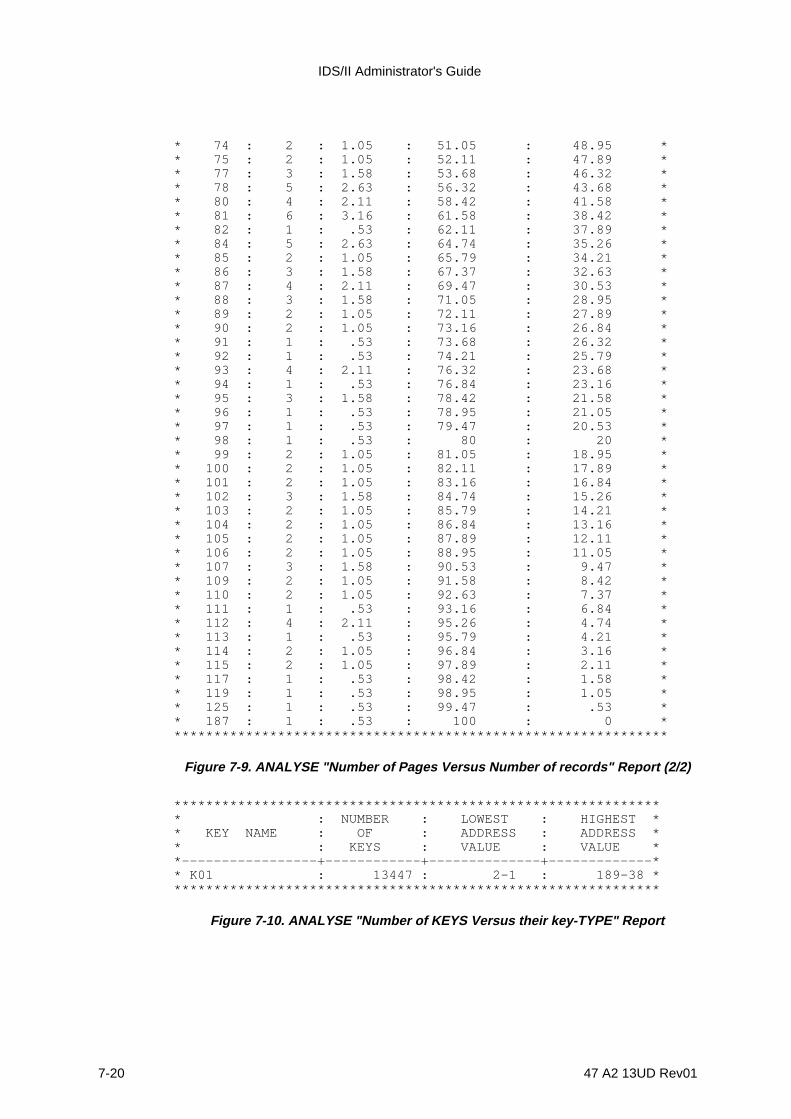
IDS/II Administrator's Guide
7-20 47 A2 13UD Rev01
* 74 : 2 : 1.05 : 51.05 : 48.95 ** 75 : 2 : 1.05 : 52.11 : 47.89 ** 77 : 3 : 1.58 : 53.68 : 46.32 ** 78 : 5 : 2.63 : 56.32 : 43.68 ** 80 : 4 : 2.11 : 58.42 : 41.58 ** 81 : 6 : 3.16 : 61.58 : 38.42 ** 82 : 1 : .53 : 62.11 : 37.89 ** 84 : 5 : 2.63 : 64.74 : 35.26 ** 85 : 2 : 1.05 : 65.79 : 34.21 ** 86 : 3 : 1.58 : 67.37 : 32.63 ** 87 : 4 : 2.11 : 69.47 : 30.53 ** 88 : 3 : 1.58 : 71.05 : 28.95 ** 89 : 2 : 1.05 : 72.11 : 27.89 ** 90 : 2 : 1.05 : 73.16 : 26.84 ** 91 : 1 : .53 : 73.68 : 26.32 ** 92 : 1 : .53 : 74.21 : 25.79 ** 93 : 4 : 2.11 : 76.32 : 23.68 ** 94 : 1 : .53 : 76.84 : 23.16 ** 95 : 3 : 1.58 : 78.42 : 21.58 ** 96 : 1 : .53 : 78.95 : 21.05 ** 97 : 1 : .53 : 79.47 : 20.53 ** 98 : 1 : .53 : 80 : 20 ** 99 : 2 : 1.05 : 81.05 : 18.95 ** 100 : 2 : 1.05 : 82.11 : 17.89 ** 101 : 2 : 1.05 : 83.16 : 16.84 ** 102 : 3 : 1.58 : 84.74 : 15.26 ** 103 : 2 : 1.05 : 85.79 : 14.21 ** 104 : 2 : 1.05 : 86.84 : 13.16 ** 105 : 2 : 1.05 : 87.89 : 12.11 ** 106 : 2 : 1.05 : 88.95 : 11.05 ** 107 : 3 : 1.58 : 90.53 : 9.47 ** 109 : 2 : 1.05 : 91.58 : 8.42 ** 110 : 2 : 1.05 : 92.63 : 7.37 ** 111 : 1 : .53 : 93.16 : 6.84 ** 112 : 4 : 2.11 : 95.26 : 4.74 ** 113 : 1 : .53 : 95.79 : 4.21 ** 114 : 2 : 1.05 : 96.84 : 3.16 ** 115 : 2 : 1.05 : 97.89 : 2.11 ** 117 : 1 : .53 : 98.42 : 1.58 ** 119 : 1 : .53 : 98.95 : 1.05 ** 125 : 1 : .53 : 99.47 : .53 ** 187 : 1 : .53 : 100 : 0 ***************************************************************
Figure 7-9. ANALYSE "Number of Pages Versus Number of records" Report (2/2)
************************************************************** : NUMBER : LOWEST : HIGHEST ** KEY NAME : OF : ADDRESS : ADDRESS ** : KEYS : VALUE : VALUE **-----------------+------------+--------------+-------------** K01 : 13447 : 2-1 : 189-38 **************************************************************
Figure 7-10. ANALYSE "Number of KEYS Versus their key-TYPE" Report
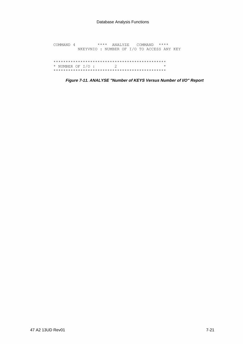
Database Analysis Functions
47 A2 13UD Rev01 7-21
COMMAND 4 **** ANALYZE COMMAND **** NKEYVNIO : NUMBER OF I/O TO ACCESS ANY KEY
*********************************************** NUMBER OF I/O : 2 ***********************************************
Figure 7-11. ANALYSE "Number of KEYS Versus Number of I/O" Report

IDS/II Administrator's Guide
7-22 47 A2 13UD Rev01
7.5 SIMULOAD COMMAND
7.5.1 Function
1. To simulate the loading of CALC records of one type into a storage area.
2. To simulate the loading of CALC records of one type with their members, subject tothe conditions given below (see Figure 7-12):
- The members are those of one or several sets of which the CALC record is owner.The LOCATION mode of these members must be VIA the corresponding set(clusters). The total number of member-types may not exceed 5.
- The members must be located in the same area as their owner, but their rangesmay be different.
- The simulation process assumes that members are chronologically storedimmediately after their owner. This does not necessarily produce the same resultsas the loading of all the owners followed by the loading of all the members.
The characteristics of records are defined in the schema. The characteristics of thestorage area are defined in the DMCL or else specified in the REDEFINE Clause ofthe command.
The CALC-key values used for the simulation can come from one of two sources:
1) The CALC-key can be supplied by the user in a sequential file. Optionally, the samefile can also supply the number of members of each type associated with each CALCrecord. This option corresponds to the case where the keys are extracted fromexisting files or are assigned to records by a user-defined algorithm.
2) Or, the CALC-key can be generated by the DBUTILITY. The algorithm whichgenerates the CALC-key is simple. The CALC-keys are thus assigned to facilitatethe numbering of records (for example , lists and catalogs). In such a case, theCALC location mode is more efficient than DIRECT location mode. The SIMULOADdistribution of CALC keys will probably not be as davantageous as a uniformsequence of keys. However, the purpose of the simulation is to detect any keyvalues which cause an overflow. Such key values can be later eliminated in theassignment of numbers to records.
Before the load simulation, DBUTILITY sorts the actual or generated CALC-keys indecreasing order of the page number to which they randomize (synonyms areordered LAST). A sort by decreasing order of page number reduces overflow.
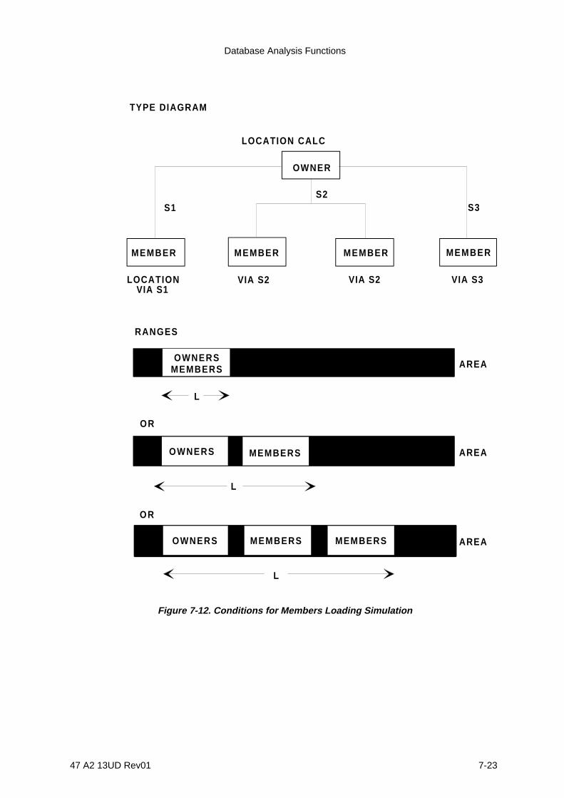
Database Analysis Functions
47 A2 13UD Rev01 7-23
S3S2
LOCATIONVIA S1
MEMBER MEMBER MEMBER MEMBER
VIA S2 VIA S2 VIA S3
TYPE DIAGRAM
LOCATION CALC
RANGES
OWNERSMEMBERS
OWNERS MEMBERS
OWNERS MEMBERS
L
L
L
OR
OR
AREA
AREA
AREAMEMBERS
OWNER
S1
Figure 7-12. Conditions for Members Loading Simulation

IDS/II Administrator's Guide
7-24 47 A2 13UD Rev01
7.5.2 General Format
SIMULOAD {OWNERS }LOAD-MODE IS { } {OWNER-MEMBERS}
CALC OWNER IS record-name [ WITHIN area-name ]
[ CLUSTERED MEMBERS ARE {record-name} ... ]
{ GENERATE KEYS FROM u THRU v INCREMENT IS w }{ READ [ m-1 ] KEYS }{ [ AFTER SKIPPING m-2 KEYS ] }{ [ LOCATION IN RECORD IS {t} ... ] }
| NPGVUSP [ WITH GRAPH ] [ INTERVAL IS n PAGES ] ] | | NPGVNRC [ WITH GRAPH ] [ INTERVAL IS n PAGES ] ] | | NCCVNCR | REPORT | NCCVNPG | | NCRVNIO | | [ |q-1 I-O |] | | KEYVCC [ THRESHOLD IS | |] | | [ |q-2 PAGES|] | | NRCVTYPE | | NCLVNPG |
[ REDEFINE AREA area-name DMCL ][| |][|NUMBER-OF-PAGES IS integer |][|NUMBER OF LINES-PER-PAGE IS integer |][|PAGE-SIZE IS integer BYTES |][|CALC-INTERVAL IS integer PAGES |][| { {PAGE p-1 THRU p-2 }} |][| {RANGE OF record-name IS { }} ... |][| { {m PAGES FROM PAGE p-1}} |]
7.5.3 Syntax Rules
1. u, v, and w are signed or unsigned decimal integers of up to 30 digits in length.
2. m-1, m-2, t, q-1, q-2, n and m are unsigned decimal integers other than 0.
3. p-1 and p-2 designate page numbers and must be written as unsigned decimalnumbers. Page numbers start from 0.

Database Analysis Functions
47 A2 13UD Rev01 7-25
7.5.4 General Rules
1. The LOAD-MODE Clause specifies whether the simulated loading is to be performedwith CALC owner records only (OWNERS) or with both owner and member records(OWNER-MEMBERS).
2. If OWNERS is specified in the LOAD-MODE Clause, the user may either supply aset of CALC-key values (READ Clause) through INFILE, or instead allow the utility togenerate a sequence of mono-item CALC-key values (GENERATE Clause).
3. If OWNER-MEMBERS is specified in the LOAD-MODE Clause, the user must supplya set of CALC-key values and the associated number-of-members for each key(READ clause) through INFILE.
4. The CALC OWNER Clause identifies which CALC record of the schema is the objectof the simulation.
5. If the CALC record is multi-area, the WITHIN phrase of the CALC OWNER Clausemust be specified to select the area involved in the simulation.
6. The CLUSTERED MEMBERS Clause defines the types of members whose loadingis to be simulated. It must be specified when the LOAD-MODE OWNER-MEMBERSoption is selected. The order of the list of member-types must correspond to theorder of the number-of-members associated with each CALC-key value of INFILE.See the subsection entitled "Simulation Input Format" further on in this section.
7. The GENERATE KEYS Clause specifies that the simulation is to be done usinggenerated CALC-key values. It may be specified only if LOAD-MODE OWNERS isselected and if the CALC-key is mono-item. The numeric CALC-key valuesgenerated are:
u, u + w, u + 2w, ... u + xwwhere u + xw < v
These numeric values are interpreted according to the data type of the CALC-keyrecorded in the schema. The possible interpretations are given below:
- If TYPE is CHARACTER, the numeric value must be positive. It is converted into anunsigned, unpacked, right-justified decimal number with digits in the range 0 to 9.The length of the CALC-key must not exceed 30 bytes.
- If type is DECIMAL or BINARY, the numeric value is converted into the typespecified. Any scale associated with the DECIMAL type is ignored.
Integers u and v must represent values which can be converted into CALC-key typeswithout truncation.
8. The READ KEYS Clause specifies that the simulation is to be done using actualCALC-key values and possibly members associated with each key value.
9. The input records required by the READ function are supplied via INFILE. Theirformat is described in the subsection entitled "Simulation Input Format", further on inthis section.
IDS/II Administrator's Guide
7-26 47 A2 13UD Rev01
10. If m-1 is specified in the READ Clause, it defines the number of records to be readfrom INFILE. If m-1 exceeds the number of records actually found before the end-of-file, the reading stops at the end of the file.
11. If m-1 is not specified in the READ Clause, the records are read up to the end of thefile.
12. If the SKIPPING phrase is specified, the first m-2 records are skipped from thebeginning of INFILE so that m-1 records can be read.
13. If the SKIPPING phrase is omitted, the records are read from the beginning ofINFILE.
14. The LOCATION phrase specifies the position within the input record of the leftmostbyte of each CALC-key item. The first position is numbered 1. t values must bewritten in the same order as specified in the CALC USING phrase of the SchemaDDL RECORD Entry. If the LOCATION phrase is omitted, all CALC-key items areconsidered contiguous with the first item starting at character position 1.
15. If a sequential file is assigned to OUTFILE, the CALC-key records, having beenpresorted in decreasing order of the page number to which they randomize, areoutput to this file. If the results of the simulation are acceptable, the file can be usedlater to optimize the actual loading of the records.
16. The REPORT Clause specifies the type of information to be produced. The firstseven options in this clause are the same in form, syntax and meaning as thosedescribed already for the ANALYSE command.
The difference is that the optional record-name cannot be specified here and that therange of pages involved in the reports includes the range of the owner and theranges of the members. These ranges are illustrated by L in the RANGES portion ofFigure 7-12.
NOTE: The first and last page numbers of each cluster are reported in the KEYVCCtable (see Figure 7-13). As this information is related to all the members of thecluster independently of their type, the information in this part of the option maybe irrelevant if the ranges of all member-types are not identical. This isillustrated by Case 3 in Figure 7-12.
The seventh option (NCLVNPG) produces a table giving the Number of CLustersVersus the Number of PaGes occupied by a cluster (see Figure 7-14). Pages are notnecessarily contiguous.
17. The REDEFINE AREA Clause introduces a group of options which allows the user tooverride the DMCL definition of the area in the object schema. In this clause, theuser may introduce new values for the following:- the number of pages in area- the number of lines-per-page (<=255)- the page size (recommended to be a multiple of 512)- the CALC interval (<=255)- The ranges of the records whose loading is being simulated (OWNER and/or
MEMBERS)
The new values must comply with the rules described for the AREA Entry of theDMCL:- the number of pages must be a multiple of the CALC interval,

Database Analysis Functions
47 A2 13UD Rev01 7-27
- a range containing CALC records must be synchronized on a CALC intervalboundary, etc
IDS/II Administrator's Guide
7-28 47 A2 13UD Rev01
NOTE: These values do not change the values in the object schema. The REDEFINEvalues are only used in place of the real schema values. If, as a result ofsimulation, the user wishes to change the schema, the must use the MNDDprocessor.
18. If a RANGE is defined in the REDEFINE Clause, it may be expressed as a numberof pages starting at a specified page or as a first and last page number pair. Forexample, the following two phrases are equivalent:
101 PAGES FROM PAGE 200
and
PAGE 200 THRU 300
If, in the schema, a record range is co-extensive with the area, the redefinition of thenumber of pages of the area implicitly redefines that record range, unless a RANGEoption is explicitly specified for this record in the REDEFINE Clause.
19. If the number of CALC-key values supplied or generated is too high, this may lead tothe saturation of the area or record range. In this case, the simulation reports willcorrespond to the number of CALC records entered prior to saturation.
In conclusion, the parameters used in the simulation are the following:
i) the TYPE of CALC-key items as defined in the DDL,
ii) for actual keys, the position of CALC-key items within input records as defined in theREAD Clause,
iii) actual key values and the associated numbers of members supplied via INFILE, orgenerated key values,
iv) the size of OWNER/MEMBERS as indicated in the report produced by the PRINTSCHEMA command of the MNDD processor.
v) the area characteristics and record ranges as defined in the DMCL or as redefined inthe REDEFINE Clause.
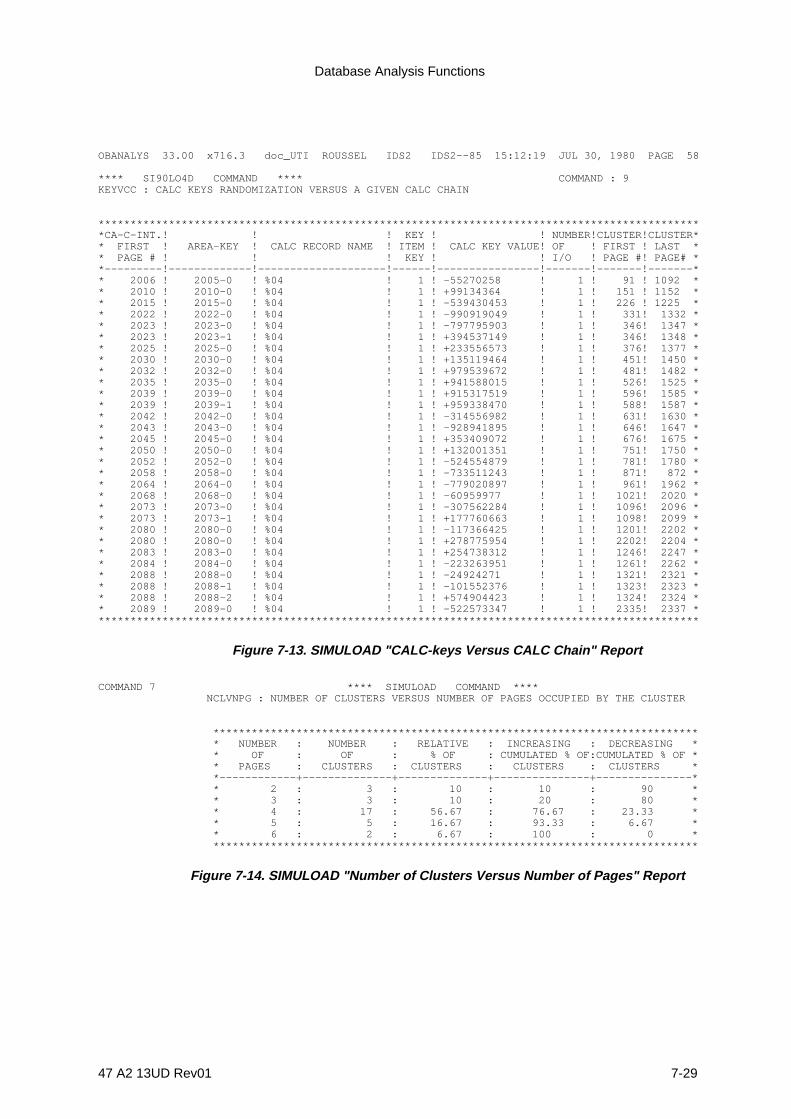
Database Analysis Functions
47 A2 13UD Rev01 7-29
OBANALYS 33.00 x716.3 doc_UTI ROUSSEL IDS2 IDS2--85 15:12:19 JUL 30, 1980 PAGE 58
**** SI90LO4D COMMAND **** COMMAND : 9KEYVCC : CALC KEYS RANDOMIZATION VERSUS A GIVEN CALC CHAIN
***********************************************************************************************CA-C-INT.! ! ! KEY ! ! NUMBER!CLUSTER!CLUSTER** FIRST ! AREA-KEY ! CALC RECORD NAME ! ITEM ! CALC KEY VALUE! OF ! FIRST ! LAST ** PAGE # ! ! ! KEY ! ! I/O ! PAGE #! PAGE# **---------!-------------!--------------------!------!----------------!-------!-------!-------** 2006 ! 2005-0 ! %04 ! 1 ! -55270258 ! 1 ! 91 ! 1092 ** 2010 ! 2010-0 ! %04 ! 1 ! +99134364 ! 1 ! 151 ! 1152 ** 2015 ! 2015-0 ! %04 ! 1 ! -539430453 ! 1 ! 226 ! 1225 ** 2022 ! 2022-0 ! %04 ! 1 ! -990919049 ! 1 ! 331! 1332 ** 2023 ! 2023-0 ! %04 ! 1 ! -797795903 ! 1 ! 346! 1347 ** 2023 ! 2023-1 ! %04 ! 1 ! +394537149 ! 1 ! 346! 1348 ** 2025 ! 2025-0 ! %04 ! 1 ! +233556573 ! 1 ! 376! 1377 ** 2030 ! 2030-0 ! %04 ! 1 ! +135119464 ! 1 ! 451! 1450 ** 2032 ! 2032-0 ! %04 ! 1 ! +979539672 ! 1 ! 481! 1482 ** 2035 ! 2035-0 ! %04 ! 1 ! +941588015 ! 1 ! 526! 1525 ** 2039 ! 2039-0 ! %04 ! 1 ! +915317519 ! 1 ! 596! 1585 ** 2039 ! 2039-1 ! %04 ! 1 ! +959338470 ! 1 ! 588! 1587 ** 2042 ! 2042-0 ! %04 ! 1 ! -314556982 ! 1 ! 631! 1630 ** 2043 ! 2043-0 ! %04 ! 1 ! -928941895 ! 1 ! 646! 1647 ** 2045 ! 2045-0 ! %04 ! 1 ! +353409072 ! 1 ! 676! 1675 ** 2050 ! 2050-0 ! %04 ! 1 ! +132001351 ! 1 ! 751! 1750 ** 2052 ! 2052-0 ! %04 ! 1 ! -524554879 ! 1 ! 781! 1780 ** 2058 ! 2058-0 ! %04 ! 1 ! -733511243 ! 1 ! 871! 872 ** 2064 ! 2064-0 ! %04 ! 1 ! -779020897 ! 1 ! 961! 1962 ** 2068 ! 2068-0 ! %04 ! 1 ! -60959977 ! 1 ! 1021! 2020 ** 2073 ! 2073-0 ! %04 ! 1 ! -307562284 ! 1 ! 1096! 2096 ** 2073 ! 2073-1 ! %04 ! 1 ! +177760663 ! 1 ! 1098! 2099 ** 2080 ! 2080-0 ! %04 ! 1 ! -117366425 ! 1 ! 1201! 2202 ** 2080 ! 2080-0 ! %04 ! 1 ! +278775954 ! 1 ! 2202! 2204 ** 2083 ! 2083-0 ! %04 ! 1 ! +254738312 ! 1 ! 1246! 2247 ** 2084 ! 2084-0 ! %04 ! 1 ! -223263951 ! 1 ! 1261! 2262 ** 2088 ! 2088-0 ! %04 ! 1 ! -24924271 ! 1 ! 1321! 2321 ** 2088 ! 2088-1 ! %04 ! 1 ! -101552376 ! 1 ! 1323! 2323 ** 2088 ! 2088-2 ! %04 ! 1 ! +574904423 ! 1 ! 1324! 2324 ** 2089 ! 2089-0 ! %04 ! 1 ! -522573347 ! 1 ! 2335! 2337 ***********************************************************************************************
Figure 7-13. SIMULOAD "CALC-keys Versus CALC Chain" Report
COMMAND 7 **** SIMULOAD COMMAND **** NCLVNPG : NUMBER OF CLUSTERS VERSUS NUMBER OF PAGES OCCUPIED BY THE CLUSTER
**************************************************************************** * NUMBER : NUMBER : RELATIVE : INCREASING : DECREASING * * OF : OF : % OF : CUMULATED % OF:CUMULATED % OF * * PAGES : CLUSTERS : CLUSTERS : CLUSTERS : CLUSTERS * *------------+--------------+--------------+---------------+---------------* * 2 : 3 : 10 : 10 : 90 * * 3 : 3 : 10 : 20 : 80 * * 4 : 17 : 56.67 : 76.67 : 23.33 * * 5 : 5 : 16.67 : 93.33 : 6.67 * * 6 : 2 : 6.67 : 100 : 0 * ****************************************************************************
Figure 7-14. SIMULOAD "Number of Clusters Versus Number of Pages" Report

IDS/II Administrator's Guide
7-30 47 A2 13UD Rev01
7.6 SIMULATION INPUT FORMAT
When SIMULOAD contains a READ Clause, the user must assign an input file to INFILEin order to supply CALC-key values and possibly the associated numbers of theirmembers. This file can have any organization, provided that it can be read sequentially.
Each INFILE record contains the following:
1) the CALC-key items,
2) optionally, the numbers of members of each type associated with the key value,
3) optionally, additional data.
The record size can be variable.
Each CALC-key item must have the TYPE defined in the schema. The position of eachCALC-key item is specified in the LOCATION phrase of the READ Clause. This position isfixed even if the record is of variable length.
The members are SIGNED BINARY 15 fields (COMP-1 in COBOL). They are placed atthe end of the record, in the order specified in the CLUSTERED MEMBERS Clause.When the record size is variable, the position of these fields is derived from the actualrecord length returned by the access method.
CALC-Ke yitem#1
data CALC-Ke yitem#2
data data no. ofmembers
a
no. ofmembers
b...
no. ofmembers
m
SIMULOAD LOAD-MODE IS OWNER-MEMBERSC A L C O W N E RCLUSTERED MEMBERS ARE record-name-arecord-name-b record-name-mREAD 10000 KEYS LOCATION IN RECORD IS 21 33R E P O R T
...
...
... .
usa g e is com p -1

Database Analysis Functions
47 A2 13UD Rev01 7-31
If LOAD-MODE is OWNERS, the INFILE record may have exactly the same format asthat of the DDL record whose loading is simulated.
IDS/II Administrator's Guide
7-32 47 A2 13UD Rev01
7.7 SORT COMMAND
7.7.1 Function
To sort records containing CALC keys of one type in the descending order of the pagenumbers to which they randomize (synonyms are ordered LAST).
The resulting sorted file is intended to optimize the actual loading of the CALC records,provided that these records are not AUTOMATIC members of any set.
7.7.2 General Format
sort
CALC OWNER IS record-name [ WITHIN area-name ]
READ [ m-1 ] KEYS [ AFTER SKIPPING m-2 KEYS ] [ LOCATION IN RECORD IS {t} ... ] [ REPORT NCCVNCR ] .
7.7.3 Syntax Rules
1. m-1, m-2, and t are unsigned decimal numbers other than 0.
7.7.4 General Rules
1. The OWNER Clause specifies the record-type corresponding to the CALC-keyswhich are to be sorted. The LOCATION mode of this record-type must be CALC.
2. The WITHIN phrase must be specified if the record-type is multi-area.
3. The records to be sorted are input via the sequential file assigned to INFILE. TheTYPE characteristic of the CALC-key items must be the one defined in the schema.However, the position of the CALC-key items and the rest of the record may bedifferent from the schema definition.
4. If m-1 is specified in the READ Clause, it defines the number of records to be readfrom INFILE. If m-1 exceeds the number of records actually found before the end-of-file, reading stops at the end of the file.

Database Analysis Functions
47 A2 13UD Rev01 7-33
5. If m-1 is not specified in the READ Clause, the records are read up to the end of thefile.
6. If the SKIPPING phrase is specified, the first m-2 records are skipped from thebeginning of INFILE and m-1 records are read.
7. If the SKIPPING phrase is omitted, the records are read from the beginning ofINFILE.
8. The LOCATION phrase specifies the position within the record of the leftmost byte ofeach CALC-key item. t values must be written in the same order as that specified inthe CALC USING phrase of the Schema DDL RECORD Entry. The number of thefirst byte within the record is 1. The position of the CALC-key items must be fixedalthough data to their right may be of variable length.
If the LOCATION phrase is omitted, all CALC-key items are considered contiguouswith the first item starting at character position 1.
9. The hashing algorithm uses the following parameters:
- the TYPE of the CALC-key items as defined in the Schema DDL,
- the position of the CALC-key items as specified in the READ Clause,
- the area characteristics (number of pages of range, CALC interval) as defined inthe DMCL.
10. If the REPORT NCCVNCR Clause is specified, a table is produced which gives thenumber of CALC chains containing a given number of synonyms. This table does notaccount for the CALC overflow. The user can, however, derive informationconcerning the amount of page/bucket overflow by considering the CALC chainswhich exceed the number of lines or the size of the page/bucket, whichever occursfirst.
11. If the REPORT Clause is omitted, no table is produced.
12. Sorted records are output to the sequential file which is assigned to OUTFILE.
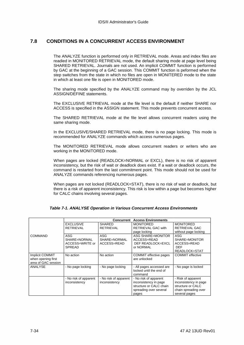
IDS/II Administrator's Guide
7-34 47 A2 13UD Rev01
7.8 CONDITIONS IN A CONCURRENT ACCESS ENVIRONMENT
The ANALYZE function is performed only in RETRIEVAL mode. Areas and index files arereadied in MONITORED RETRIEVAL mode, the default sharing mode at page level beingSHARED RETRIEVAL. Journals are not used. An implicit COMMIT function is performedby GAC at the beginning of a GAC session. This COMMIT function is peformed when thestep switches from the state in which no files are open in MONITERED mode to the statein which at least one file is open in MONITORED mode.
The sharing mode specified by the ANALYZE command may by overriden by the JCLASSIGN/DEFINE statements.
The EXCLUSIVE RETRIEVAL mode at the file level is the default if neither SHARE norACCESS is specified in the ASSIGN statement. This mode prevents concurrent access.
The SHARED RETRIEVAL mode at the file level allows concurrent readers using thesame sharing mode.
In the EXCLUSIVE/SHARED RETRIEVAL mode, there is no page locking. This mode isrecommended for ANALYZE commands which access numerous pages.
The MONITORED RETRIEVAL mode allows concurrent readers or writers who areworking in the MONITORED mode.
When pages are locked (READLOCK=NORMAL or EXCL), there is no risk of apparentinconsistency, but the risk of wait or deadlock does exist. If a wait or deadlock occurs, thecommand is restarted from the last commitment point. This mode should not be used forANALYZE commands referencing numerous pages.
When pages are not locked (READLOCK=STAT), there is no risk of wait or deadlock, butthere is a risk of apparent inconsistency. This risk is low within a page but becomes higherfor CALC chains involving several pages.
Table 7-1. ANALYSE Operation in Various Concurrent Access Environments
Concurrent Access EnvironmentsEXCLUSIVERETRIEVAL
SHAREDRETRIEVAL
MONITOREDRETRIEVAL GAC withpage locking
MONITOREDRETRIEVAL GACwithout page locking
COMMAND ASGSHARE=NORMALACCESS=WRITE orSPREAD
ASGSHARE=NORMALACCESS=READ
ASG SHARE=MONITORACCESS=READ DEF READLOCK=EXCLor NORMAL
ASGSHARE=MONITORACCESS=READ DEFREADLOCK=STAT
Implicit COMMITwhen opening firstarea of GAC session
No action No action COMMIT effective pagesare unlocked
COMMIT effective
ANALYSE - No page locking - No page locking - All pages accessed arelocked until the end ofcommand
- No page is locked
- No risk of apparentinconsistency
- No risk of apparentinconsistency
- No risk of apparentinconsistency in pagestructure or CALC chainspreading over severalpages
- Risk of apparentinconsistency in pagestructure or CALCchain spreading overseveral pages
Database Analysis Functions
47 A2 13UD Rev01 7-35
7.9 PERFORMANCE ASPECTS
The space and time overhead of the DBANALYS functions is influenced by the number ofpages which are being analyzed in the database area or index. The most importantconsiderstion in the analysis is the number of records or keys that it contains (or willcontain).
7.9.1 DBUTILITY Work-files
Depending on the DBANALYS function, DBUTILITY uses either one or both of the twowork files, a VMM work file and/or a Sort work file, which are described below. See Figure7-15.
7.9.2 VMM WORK FILE
This file is a Virtual Memory random file which is allocated dynamically on the backingstore of the resident disk. It consists of two parts:
• Part 1 is a reduced image of the database file and contains information relative to eachpage.
• Part 2 contains information about each record in the area.
Table 7-2 shows the approximate space overhead of the VMM work-file for differentcombinations of commands and reports. In the table, the space overhead is expressed asthe number of bytes which are required by related information for a database page orrecord. When several reports are requested, the actual space overhead is the amount ofspace required to accomodate the report which needs the most storage space.
There are two reasons why a request for VMM file space may be aborted:
1) The total VMM space available to all the process-groups running concurrently islimited. Saturation (backing store overload) is reported by the following message:
*** 2 - 10 SYSTEM ERROR RC = ... 6, BSOVLD

IDS/II Administrator's Guide
7-36 47 A2 13UD Rev01
2) The total size of the VMM files of a given process-group is limited. Saturation (VMMtable overflow) is reported by the following message:
*** 2 - 10 SYSTEM ERROR RC = ... 14, TABOV
7.9.3 SORT WORK FILE
This is the work-file required by the SORT procedures which are invoked by the executionof a SIMULOAD or SORT command.
The file is either implicitly assigned and allocated as a temporary file on a resident disk orexplicitly assigned by a SORTWORK statement. If SORTWORK specifies a temporaryfile, the file is allocated dynamically. If SORTWORK specifies a permanent file, the filemust have been previously preallocated by PREALLOC and preformatted by SORTFMT.
If it is not defined by SORTWORK, the size of the file is calculated automatically from thenumber of records specified in the READ Clause. The record size is assumed to be equalto the maximum record size read from the INFILE label, plus 4 bytes for the data-base-key. If the number of records is not present in the READ Clause, the default file size is 10cylinders.
If the work-file is to be defined by SORTWORK, an estimate of the amount of space to bepreallocated can be made by referring to the information given in the Sort/Merge UtilitiesUser's Guide.
7.9.4 Hints for Use
Do not request reports which you will not need. For instance, the NCRVNIO and KEYVCCreports use large amounts of VMM space and are time-consuming. They thereforepenalize SIMULOAD OWNERS considerably. When requesting a KEYVCC report, usethe THRESHOLD option to limit the amount of printing.
Keep the INFILE record size to a minimum in order to optimize the space and timeoverhead of the sort.
Do not run DBANALYS functions concurrently with other processors which need VMMspace. The COBOL processor is a good example.
After simulation, when CALC records are to be loaded in descending order of the pagenumber to which they randomize, the following methods are suggested:
• If the future database record is large compared to its key:- extract the key value to constitute INFILE,- run SIMULOAD without OUTFILE until the best DMCL characteristics are
determined,- then, run SORT with the complete database records.
Database Analysis Functions
47 A2 13UD Rev01 7-37
• If the future database records are small, these records can constitute INFILEthemselves. In this case, a different OUTFILE is assigned for every SIMULOAD run.When the best DMCL characteristics are determined, the corresponding OUTFILE isreselected for initial loading. In this case, there will be no need to run the SORTcommand.
When both the database area and the number of records are very large, it may beadvisable to simulate a small-scale loading according to one of the following methods:
- Method 1: Retain the real characteristics of the database area and runSIMULOAD with various samples of the CALC-key values. Ifeach sample spreads evenly, the complete set of CALC-keyvalues should yield a good distribution.
- Method 2: Reduce the number of pages and the number of recordsproportionally, and choose a prime number for the number ofbuckets. If SIMULOAD yields good results in theseconditions, the full-size database should react iln the samemanner.

IDS/II Administrator's Guide
7-38 47 A2 13UD Rev01
ANALYSE
SCHEMA
ANALYSE
VMMWORK-FILE
REPORT
SIMULOAD
SCHEMA
VMMWORK-FILE
INFILE
(READ) SIMULOAD
OUTFILE SORTWORK-FILE
REPORT
SCHEMA
OUTFILE
INFILE
SORT
SORTWORK-FILE
SORT
REPORT
DATABASEFILE
Figure 7-15. DBUTILITY Work-files for DBANALYS functions

Database Analysis Functions
47 A2 13UD Rev01 7-39
Table 7-2. DBUTILITY VMM Work-file Size Estimates for DBANALYS Functions
PART-1 SIZE* (page
information)
PART-2 SIZE** (record
information)ANALYSE
AREAANALYSE
INDEXSIMULOAD ANALYSE
AREASIMULOADOWNERS
SIMULOADOWNERS-MEMBERS
R NPGVUSP 3 3 3 - - -E NPGVNRCP NCCVNCR 7O NCCVNPG 11R NCRVNIO 19 13 6 ou 8 *** 6 6T KEYVCC 12+calc-key lgt 10+calc-key lgt 14+calc-key lgt
NCLVNPG 3 20NPGVNKEY 3KEYVTYPE -NKEYVNIO -
* Figures are expressed in bytes per database page** Figures are expressed in bytes per database record*** 8 when NCRVNIO scope is limited to specified record-types (NCRVNIO record-name...); 6 otherwise.

IDS/II Administrator's Guide
7-40 47 A2 13UD Rev01
7.10 DBANALYS EXAMPLES
Example 1
In this example, which is based on an existing schema, named SCH-CMDB, which hasthree areas (AA, AB and AC), three tables will be produced:
1) a table showing all CALC chains which occupy a minimum of 3 pages in area AA,
2) a table showing the distribution of all records of the type CUSTOMER in the first 100pages of area A
3) and a table showing the number of page transfers required to retrieve CALC recordsin area AC.
$JOB CMIDPC, USER=RF, PROJECT=TP;STEP H_DBUTILITY SYS;SIZE 100;ASSIGN COMFILE *COMSTREAM;ASSIGN DDLIB1 DB.BINLIB SHARE=DIR;ASSIGN AA DB.FAA SHARE=NORMAL ACCESS=READ;ASSIGN AB DB.FAB SHARE=NORMAL ACCESS=READ;ASSIGN AC DB.FAC SHARE=NORMAL ACCESS=READ;ENDSTEP;$INPUT COMSTREAM;SCHEMA SCH-CMDB.ANALYSE AREA NAME IS AA REPORT KEYVCC THRESHOLD IS 3 PAGES.ANALYSE AREA NAME IS AB RANGE IS PAGE 0 THRU 99 REPORT NPGVNRC CUSTOMER.ANALYSE AREA NAME IS AC REPORT NCRVNIO.$ENDINPUT;$ENDJOB;
Example 2
In this example, the user wishes to simulate the effect of different area designs for areasAA and AC. For the purposes of this example, assume that record-type FCR is CALC andis also the the owner of two other record-types, MRA and MRB. All these record-types arein area AA and are mono-area.
In area AC, there is a mono-area record-type named OCR which is CALC. CALC-keys ofFCR and OCR are mono-item.
Database Analysis Functions
47 A2 13UD Rev01 7-41
For record FCR, the user has a file (PC.SIMFIL) with about 8000 records of the followingformat:
+--------------+--------------+---------------+| + | || CALC-key + No. type MRA | No. type MRB || + members | members |+--------------+--------------+---------------+
Schema defined COMP-1 COMP-1
For CALC record-type OCR, simulation will be done by generating 1000 values in therange 50,000 to 924,000 (increment of 874). The records are to be placed in the first 503pages of area AC instead of the whole area. The JCL sequence is shown below:
$JOB CMIDPC, USER=RF, PROJECT=TP;STEP H_DBUTILITY SYS;SIZE 100;ASSIGN COMFILE *COML;ASSIGN DDLIB1 DB.BINLIB SHARE=DIR;ASSIGN INFILE PC.SIMFIL DVC=MT/T9 MD=1411;ENDSTEP;$INPUT COML;SCHEMA SCH-CMDB.SIMULOAD LOAD-MODE IS OWNER-MEMBERS CALC OWNER IS FCR CLUSTERED MEMBERS ARE MRA MRB READ 8500 KEYS REPORT NPGVUSP NCCVNCR NCCVNPG NCRVNIO REDEFINE AREA AA DMCL NUMBER-OF-PAGES IS 601 LINES-PER-PAGE IS 27.SIMULOAD LOAD-MODE IS OWNERS CALC OWNER IS OCR GENERATE KEYS FROM 50000 THRU 924000 INCREMENT IS 874 REPORT NCCVNCR NCCVNPG NCRVNIO KEYVCC THRESHOLD IS 6 I-O REDEFINE AREA AC DMCL RANGE OF OCR IS 503 PAGES FROM PAGE 0.$ENDINPUT;$ENDJOB;
NOTE: Since there are no ANALYSE commands, no area files are assigned in theSTEP statement.
Example 3
Let us assume that several simulation runs have allowed the user to determine the bestDMCL characteristics for a CALC record-type CUSTOMER and that the final DMCL hasbeen translated.
If CUSTOMER is not an AUTOMATIC member of any set, the loading of the CUSTOMERrecords can be optimized in terms of time and page overflow. This is done by, first, sortingthe records in descending order of the page numbers to which they randomize. Thisfunction is performed by the SORT command of DBUTILITY.

IDS/II Administrator's Guide
7-42 47 A2 13UD Rev01
If the sequential file INFILE contains 60,000 CUSTOMER records whose CALC-keylocation is 14, the JCL sequence is shown below:
$JOB PRESORT, USER=ADMIN, PROJECT=DBINSTAL;STEP H_DBUTILITY SYS OPTIONS = 'SCHEMA SCH-CMDB.SORT CALC OWNER IS CUSTOMER READ 60000 KEYS LOCATION IN RECORD IS 14 REPORT NCCVNCR.';SIZE 100;ASSIGN DDLIB1 DB.BINLIB SHARE=DIR;ASSIGN INFILE CUSTOMER-LIST DVC=MT/T9 MD=P3120;ASSIGN OUTFILE CUSTOMER-LOAD DVC=MT/T9 MD=P3722;ENDSTEP;$ENDJOB;

47 A2 13UD Rev01 8-1
8. Database Validate and Patch Function
8.1 DBVALID FUNCTIONS
The Database Validate functions and Patch functions are outlined below:
1) Validate Function 1: validates the set pointers of one or more set-types in thedatabase. It also validates the UFAS page structure of all the pages of the storageareas involved.
The validation consists of a sequential search of the area for the DATA-BASE-KEYand the NEXT and PRIOR pointers for each record that is part of a set occurrence ofthe specified set-types. The data-base-keys and pointers are then sorted by set-type,set occurrence within set-type (defined by owner data-base-key), and by data-base-key values.
The result of the sort should be a sequence of groups, each containing threeelements for each data-base-key value: 1) DATA-BASE-KEY, 2) NEXT FOR, 3)PRIOR FOR. Therefore, for each record of a set occurrence, there is one and onlyone record pointing to it in the NEXT direction, and one and only one record pointingto it in the PRIOR direction.
2) Validate Function 2: validates one or more pages of a storage area.
The validation applies to the UFAS page structure and to the IDS structure of thestorage records contained in the page. A checking option exists which verifies thatset pointers pointing outside of a validated page lead to records participating in thesame set occurrence.
3) Validate Function 3: validates CALC-CHAINS.
This is a validation of the CALC chains of one or more areas of the database.
4) Validate Function 4: validates CHECK Clauses.
This is a validation the CHECK Clauses for given record-types.
5) Patch Function 1: patches a storage record.
The header, set pointers, and fields can be patched separately. Since the record isreferenced by its line number, this patch function assumes that the page structure(header, locators) is valid.

IDS/II Administrator's Guide
8-2 47 A2 13UD Rev01
6) Patch Function 2: patches a page of a storage area.
The header and data can be patched separately. This patch function is to be usedwhen the page structure is corrupted.
7) Patch Function 3: patches the IDS/II labels of a storage area or index file.
This patch function can be used to:
- reset the TRANSIENT and INCONSISTENT STATE flags,
- modify the reference to the schema,
- to modify the contents of the labels.
8) Patch Function 4: reconnects CALC records.
Each selected CALC record is reconnected to its correct CALC chain, according tothe value of its CALC-key.
9) Patch Function 5: builds index files corresponding to keys.
This function builds the index file corresponding to one or more keys, or to a portoinof the index.
10) Patch Function 6: deletes one or more keys.
This function deletes one or more keys from the index file. It is executed when theuser deletes one or more keys from the schema.
All of the validation and patch functions listed above are fully described in thisseciton.

Database Validate and Patch Function
47 A2 13UD Rev01 8-3
8.2 DBVALID COMMAND LANGUAGE
8.2.1 Syntax Conventions
The syntax rules, reserved words and descriptive notations are described in the Prefaceof this manual.
8.2.2 Types of Command
The following ten commands are described in detail in the following subsections:
• VALIDATE POINTERS• VALIDATE PAGE• PATCH RECORD• PATCH PAGE• PATCH LABEL• VALIDATE CHECK CLAUSES• VALIDATE CALC-CHAINS• RECONNECT RECORD• BUILD-KEY• DELETE-KEY
IDS/II Administrator's Guide
8-4 47 A2 13UD Rev01
8.3 VALIDATE POINTERS COMMAND
8.3.1 Function
To validate the IDS/II set pointers of one or more set-types in the database. To validatethe UFAS page structure of all the pages of the areas involved.
8.3.2 General Format
{ALL }VALIDATE POINTERS OF { } SETS {{set-name} ... }
[ AREA NAMES ARE {area-name} ... ] [ STOP AFTER integer ERRORS ] [ STATISTICS ] [ DEASSIGN ]
8.3.3 Rules
1. If set-name ... is specified, only the set-types in the list will be validated.
2. If ALL is specified, all the set-types of the schema will be validated.
3. If the AREA Clause is omitted, all the areas which contain record-types participatingin the set-types specified must be assigned.
4. The AREA Clause restricts the validation to the areas specified in the clause,provided that the set occurrences encountered during the search do not extendbeyond the group of areas specified.
NOTE: In order to check the UFAS page structure, entire areas are scanned, not simplythe ranges which correspond to the tenants of the set-types validated.
5. The STOP ... ERRORS Clause will stop the processing after a specified number oferrors.
NOTE: A set occurrence containing errors is counted as one error, even though severalinconsistencies may be detected in that set occurrence.
When an error is discovered in the structure of a page during the sequential searchof an area, the records of the page which participate in the set-types validated maybe inaccessible (missing owner or member). This can cause additional errors to bedetected after the sort of the set pointers.
Database Validate and Patch Function
47 A2 13UD Rev01 8-5
6. If the STOP ... ERRORS Clause is not specified, processing continuesindependently of the number of errors detected. In any event, whether the STOPClause is specified or not, it is a good idea to limit the number of lines of the reportby inserting the LINES parameter in the STEP statement.
7. If the STASTISTICS Clause is specified, the VALIDATE POINTERS commandproduces the following tables:- a table for each set-type validated. This table indicates the number of set
occurrences containing a given number of members (or, more precisely, thenumber of members within a certain range of values),
- a table showing the total number of records of each record-type participating inthe set-types validated. The number of records shown includes anydisconnected members retrieved during the search of the areas.
8. If the STATISTICS Clause is not specified, no statistics are produced.
9. If the DEASSIGN Clause is not specified, the areas remain assigned to the step untilthe end of the step.
10. If the DEASSIGN Clause is specified, the areas are deassigned as soon as theyhave been searched sequentially. These areas are then available to other stepswhile VALIDATE continues the sort and the interpretation of the results. The areaswhich are deassigned are unavailable to further commands in the same DBUTILITYstep.
11. The VALIDATE POINTERS command does not check the inter-page CALC-chain-information.
8.3.4 Interpretation of the VALIDATE POINTERS Report
Figures 8-1 through 8-7 show partial reports about a database. In this database,inconsistencies have been artifically created by restoring three areas with save copieswhich belong to different generations of the database.
Figures 8-1 through 8-6 illustrate the SYSOUT format. Figure 8-7 illustrates theTERMINAL format.
Figure 8-8 illustrates the tables produced by the STATISTICS option.
Each set occurrence which contains an error is identified by its set-type and the data-base-key of its owner. The records which are considered as tenants of this set occurrenceare listed below:
1) THE OWNER, which can have one of the two statuses described below:- The OWNER is present: That is, the record itself has been retrieved- The OWNER is missing: In this case, the data-base-key of the record is the one
found in the OWNER pointer of the actual members of the set. However, therecord associated with this data-base-key either does not exist or does not havethe same type as the owner of the set-type.
2) The ACTUAL MEMBERS, which have been retrieved and whose OWNER pointerreferences the data-base-key of the owner.
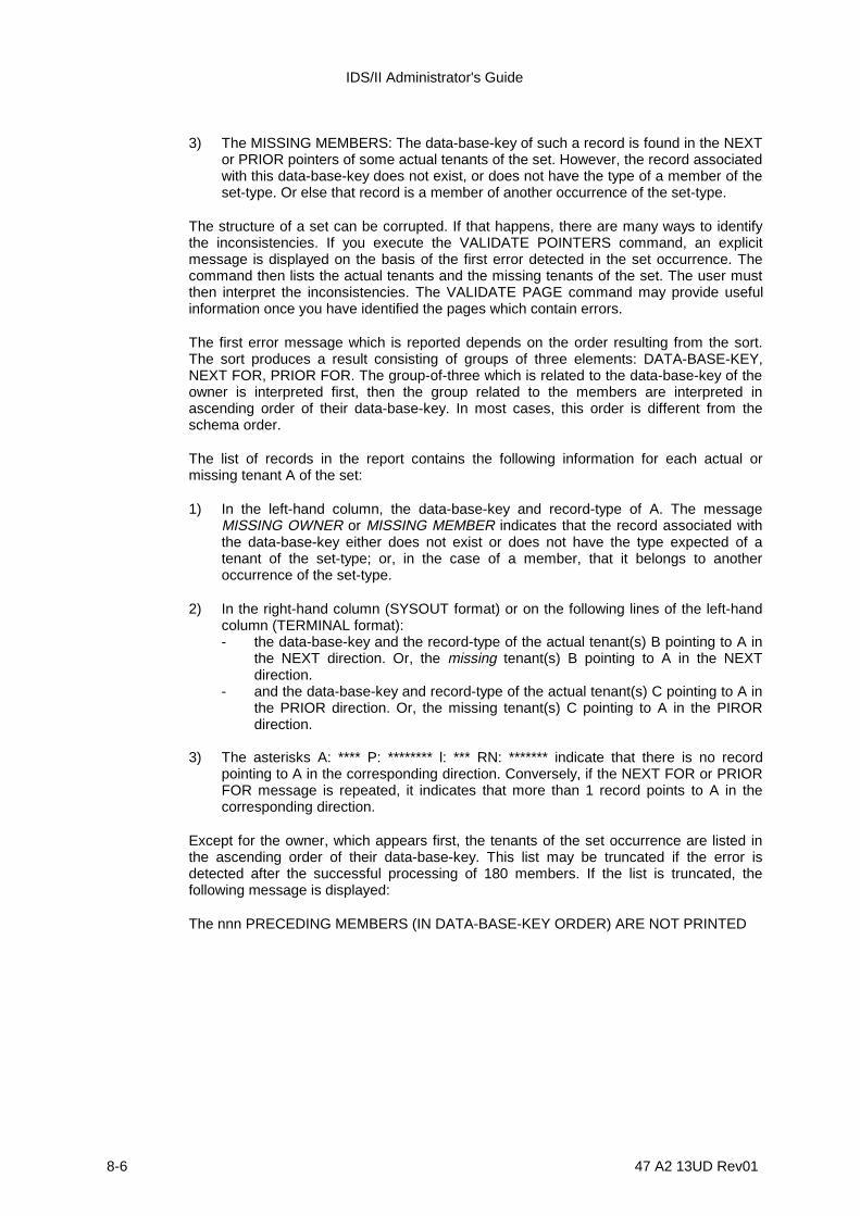
IDS/II Administrator's Guide
8-6 47 A2 13UD Rev01
3) The MISSING MEMBERS: The data-base-key of such a record is found in the NEXTor PRIOR pointers of some actual tenants of the set. However, the record associatedwith this data-base-key does not exist, or does not have the type of a member of theset-type. Or else that record is a member of another occurrence of the set-type.
The structure of a set can be corrupted. If that happens, there are many ways to identifythe inconsistencies. If you execute the VALIDATE POINTERS command, an explicitmessage is displayed on the basis of the first error detected in the set occurrence. Thecommand then lists the actual tenants and the missing tenants of the set. The user mustthen interpret the inconsistencies. The VALIDATE PAGE command may provide usefulinformation once you have identified the pages which contain errors.
The first error message which is reported depends on the order resulting from the sort.The sort produces a result consisting of groups of three elements: DATA-BASE-KEY,NEXT FOR, PRIOR FOR. The group-of-three which is related to the data-base-key of theowner is interpreted first, then the group related to the members are interpreted inascending order of their data-base-key. In most cases, this order is different from theschema order.
The list of records in the report contains the following information for each actual ormissing tenant A of the set:
1) In the left-hand column, the data-base-key and record-type of A. The messageMISSING OWNER or MISSING MEMBER indicates that the record associated withthe data-base-key either does not exist or does not have the type expected of atenant of the set-type; or, in the case of a member, that it belongs to anotheroccurrence of the set-type.
2) In the right-hand column (SYSOUT format) or on the following lines of the left-handcolumn (TERMINAL format):- the data-base-key and the record-type of the actual tenant(s) B pointing to A in
the NEXT direction. Or, the missing tenant(s) B pointing to A in the NEXTdirection.
- and the data-base-key and record-type of the actual tenant(s) C pointing to A inthe PRIOR direction. Or, the missing tenant(s) C pointing to A in the PIRORdirection.
3) The asterisks A: **** P: ******** l: *** RN: ******* indicate that there is no recordpointing to A in the corresponding direction. Conversely, if the NEXT FOR or PRIORFOR message is repeated, it indicates that more than 1 record points to A in thecorresponding direction.
Except for the owner, which appears first, the tenants of the set occurrence are listed inthe ascending order of their data-base-key. This list may be truncated if the error isdetected after the successful processing of 180 members. If the list is truncated, thefollowing message is displayed:
The nnn PRECEDING MEMBERS (IN DATA-BASE-KEY ORDER) ARE NOT PRINTED
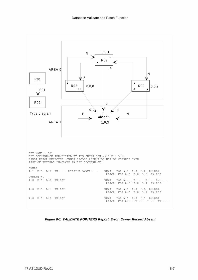
Database Validate and Patch Function
47 A2 13UD Rev01 8-7
R01
S01R02
P
P
N
N0
AREA 0
AREA 1
Type diagramabsent
0,0,1
R02
R02
0
1,0,3
P
N
0,0,20,0,0
0
R02
SET NAME : S01SET OCCURRENCE IDENTIFIED BY ITS OWNER DBK (A:1 P:0 L:3)FIRST ERROR DETECTED: OWNER RECORD ABSENT OR NOT OF CORRECT TYPELIST OF RECORDS INVOLVED IN SET OCCURRENCE :
OWNERA:1 P:0 L:3 RN: ... MISSING OWNER ... NEXT FOR A:0 P:0 L:2 RN:R02 PRIOR FOR A:0 P:0 L:0 RN:R02MEMBER(S)A:0 P:0 L:0 RN:R02 NEXT FOR A:... P:... L:... RN:.... PRIOR FOR A:0 P:0 L:1 RN:R02
A:0 P:0 L:1 RN:R02 NEXT FOR A:0 P:0 L:0 RN:R02 PRIOR FOR A:0 P:0 L:2 RN:R02
A:0 P:0 L:2 RN:R02 NEXT FOR A:0 P:0 L:1 RN:R02 PRIOR FOR A:... P:... L:... RN:....
0
Figure 8-1. VALIDATE POINTERS Report. Error: Owner Record Absent
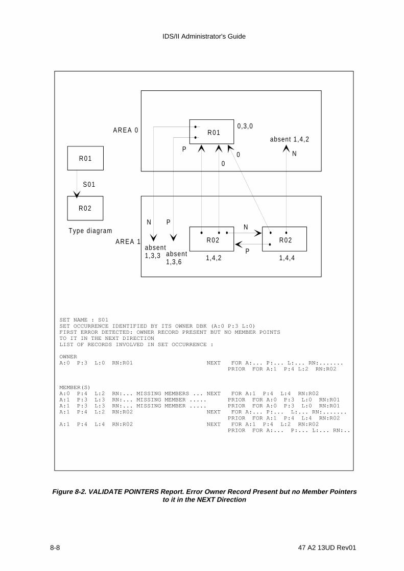
IDS/II Administrator's Guide
8-8 47 A2 13UD Rev01
R01
S01
R01
R02 R02
absent1,3,6
absent1,3,3
0,3,0
1,4,41,4,2
N P
P
P
N
N00
AREA 0
AREA 1
Type diagram
R02
SET NAME : S01SET OCCURRENCE IDENTIFIED BY ITS OWNER DBK (A:0 P:3 L:0)FIRST ERROR DETECTED: OWNER RECORD PRESENT BUT NO MEMBER POINTSTO IT IN THE NEXT DIRECTIONLIST OF RECORDS INVOLVED IN SET OCCURRENCE :
OWNERA:0 P:3 L:0 RN:R01 NEXT FOR A:... P:... L:... RN:....... PRIOR FOR A:1 P:4 L:2 RN:R02
MEMBER(S)A:0 P:4 L:2 RN:... MISSING MEMBERS ... NEXT FOR A:1 P:4 L:4 RN:R02A:1 P:3 L:3 RN:... MISSING MEMBER ..... PRIOR FOR A:0 P:3 L:0 RN:R01A:1 P:3 L:3 RN:... MISSING MEMBER ..... PRIOR FOR A:0 P:3 L:0 RN:R01A:1 P:4 L:2 RN:R02 NEXT FOR A:... P:... L:... RN:....... PRIOR FOR A:1 P:4 L:4 RN:R02A:1 P:4 L:4 RN:R02 NEXT FOR A:1 P:4 L:2 RN:R02 PRIOR FOR A:... P:... L:... RN:..
absent 1,4,2
Figure 8-2. VALIDATE POINTERS Report. Error Owner Record Present but no Member Pointersto it in the NEXT Direction
Database Validate and Patch Function
47 A2 13UD Rev01 8-9
AREA 0
AREA 1
S02
R04
P
R03
R04 P
P
N
N
N
0 0
0,15,00,14,1
0,14,0
absent 0 ,15,3
1,14,6
0
R03R04
R04
SET NAME : S02SET OCCURRENCE IDENTIFIED BY ITS OWNER DBK (A:0 P:14 L:0)FIRST ERROR DETECTED: OWNER RECORD PRESENT BUT MORE THAN ONEMEMBER POINT TO IT IN THE PRIOR DIRECTIONLIST OF RECORDS INVOLVED IN SET OCCURRENCE :
OWNERA:0 P:14 L:0 RN:R03 NEXT FOR A:0 P:15 L:0 RN:R04 PRIOR FOR A:0 P:14 L:1 RN:R04 PRIOR FOR A:1 P:14 L:6 RN:R04
MEMBER(S)A:0 P:14 L:1 RN:R04 NEXT FOR A:0 P:14 L:0 RN:R03 PRIOR FOR A:0 P:15 L:0 RN:R04
A:0 P:15 L:0 RN:R04 NEXT FOR A:0 P:14 L:1 RN:R04 PRIOR FOR A:0 P:14 L:0 RN:R03
A:0 P:15 L:6 RN: ...MISSING MEMBER... NEXT FOR A:1 P:14 L:6 RN:R04A:1 P:14 L:6 RN:R04 NEXT FOR A:... P:... L:.... RN:... PRIOR FOR A:... P:... L:.... RN:.
Figure 8-3. VALIDATE POINTERS Report. Error: Owner Record Present but More Than OneMember Points to it in the PRIOR Direction
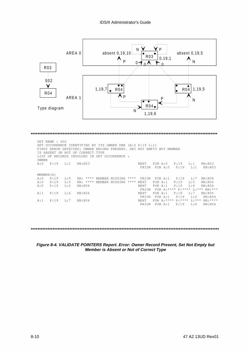
IDS/II Administrator's Guide
8-10 47 A2 13UD Rev01
R03
R04
R04
R04
P
P P
N
N
N
0 0 0
N PAREA 0
AREA 1
S02
Type d iagram
absent 0,19,10 absent 0,19,50,19,1
1,19,7
1,19,6
1,19,5
R03
R04
***************************************************************************************************************
****************************************************************************************************************
SET NAME : S02SET OCCURRENCE IDENTIFIED BY ITS OWNER DBK (A:0 P:19 L:1)FIRST ERROR DETECTED: OWNER RECORD PRESENT, SET NOT EMPTY BUT MEMBERIS ABSENT OR NOT OF CORRECT TYPELIST OF RECORDS INVOLVED IN SET OCCURRENCE :OWNERA:0 P:19 L:1 RN:R03 NEXT FOR A:0 P:19 L:1 RN:R03 PRIOR FOR A:0 P:19 L:1 RN:R03
MEMBER(S)A:0 P:19 L:0 RN: **** MEMBER MISSING **** PRIOR FOR A:1 P:19 L:7 RN:R04A:0 P:19 L:5 RN: **** MEMBER MISSING **** NEXT FOR A:1 P:19 L:5 RN:R04A:0 P:19 L:5 RN:R04 NEXT FOR A:1 P:19 L:6 RN:R04 PRIOR FOR A:**** P:**** L:*** RN:***A:1 P:19 L:6 RN:R04 NEXT FOR A:1 P:19 L:7 RN:R04 PRIOR FOR A:1 P:19 L:5 RN:R04A:1 P:19 L:7 RN:R04 NEXT FOR A:**** P:**** L:*** RN:**** PRIOR FOR A:1 P:19 L:6 RN:R04
Figure 8-4. VALIDATE POINTERS Report. Error: Owner Record Present, Set Not Empty butMember is Absent or Not of Correct Type

Database Validate and Patch Function
47 A2 13UD Rev01 8-11
AREA 0
AREA 2
AREA 1
P
P
P
N
NN
N
R09
R07
R08
R08
0,22,7 0,23,6
0 0
1,23,300
P 2,23,4P 2,22,4
P
N1,23,2
N
1,22,1
R09 R09
R07
R08 R09
S04
Type d iagram
R080
***********************************************************************************************************SET NAME : S04SET OCCURRENCE IDENTIFIED BY ITS OWNER DBK (A:0 P:23 L:3)FIRST ERROR DETECTED: MEMBER RECORD PRESENT BUT MORE THAN ONERECORD POINT TO IT IN THE NEXT DIRECTIONLIST OF RECORDS INVOLVED IN SET OCCURRENCE :OWNERA:1 P:23 L:3 RN:R07 NEXT FOR A:1 P:22 L:1 RN:R08 PRIOR FOR A:1 P:23 L:2 RN:R08
MEMBER(S)A:0 P:22 L:7 RN:R08 NEXT FOR A:1 P:23 L:2 RN:R08 NEXT FOR A:2 P:22 L:4 RN:R09 PRIOR FOR A:1 P:22 L:1 RN:R08A:0 P:23 L:6 RN:R09 NEXT FOR A:*** P:*** L:*** RN:***** PRIOR FOR A:2 P:23 L:4 RN:R09A:1 P:22 L:1 RN:R08 NEXT FOR A:0 P:22 L:7 RN:R08 PRIOR FOR A:1 P:23 L:3 RN:R07A:1 P:23 L:2 RN:R08 NEXT FOR A:1 P:23 L:3 RN:R07 PRIOR FOR A:0 P:23 L:6 RN:R09A:2 P:22 L:4 RN:R09 NEXT FOR A:2 P:23 L:4 RN:R09 PRIOR FOR A:0 P:22 L:7 RN:R08A:2 P:23 L:4 RN:R09 NEXT FOR A:0 P:23 L:6 RN:R09 PRIOR FOR A:2 P:22 L:4 RN:R09
***********************************************************************************************************
0
Figure 8-5. VALIDATE POINTERS Report. Error: Member Record Present but More than OneRecord Points to it in the NEXT Direction

IDS/II Administrator's Guide
8-12 47 A2 13UD Rev01
R08 R08 R09
absent1,25,6
absent0,25,5
P P
P
P
R07P
NN N
N
N
0 0 0 0
0,25,2 0,25,3 0,26,5
1,26,4
2,25,1
AREA 0
AREA 1
AREA 2
R07
R08 R09
S04
********************************************************************************************************
*******************************************************************************************************SET NAME : S04SET OCCURRENCE IDENTIFIED BY ITS OWNER DBK (A:2 P:25 L:1)FIRST ERROR DETECTED: MEMBER RECORD PRESENT BUT NO OTHER RECORDPOINTS TO IT IN THE PRIOR DIRECTIONLIST OF RECORDS INVOLVED IN SET OCCURRENCE :
OWNERA:2 P:25 L:1 RN:R07 NEXT FOR A:0 P:26 L:5 RN:R09 PRIOR FOR A:0 P:25 L:2 RN:R08
MEMBER(S)A:0 P:25 L:2 RN:R08 NEXT FOR A:2 P:25 L:1 RN:R07 NEXT FOR A:0 P:25 L:3 RN:R08A:0 P:25 L:3 RN:R08 NEXT FOR A:0 P:25 L:2 RN:R08 PRIOR FOR A:*** P:**** L:*** RN:***A:0 P:25 L:5 RN:**** MISSING MEMBER **** PRIOR FOR A:1 P:26 L:4 RN:R09A:0 P:26 L:5 RN:R09 NEXT FOR A:1 P:26 L:4 RN:R09 PRIOR FOR A:2 P:25 L:1 RN:R07A:1 P:25 L:6 RN:**** MISSING MEMBER **** NEXT FOR A:0 P:25 L:3 RN:R08A:1 P:26 L:4 RN:R09 NEXT FOR A:*** P:**** L:*** RN:**** PRIOR FOR A:0 P:26 L:5 RN:R09
Figure 8-6. VALIDATE POINTERS Report. Error: Member Record Present but No Other RecordPoints to it in the PRIOR Direction
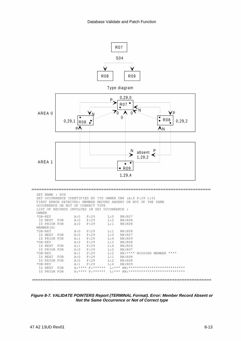
Database Validate and Patch Function
47 A2 13UD Rev01 8-13
AREA 0
R08
R09
AREA 1
R07
absent1,29,2
0,29,0
0,29,1 0,29,2
P
0
P
00
NP
PN
1,29,4
N
R08
N
Type diagram
R07
R08 R09
S04
SET NAME : S04SET OCCURRENCE IDENTIFIED BY ITS OWNER DBK (A:0 P:29 L:0)FIRST ERROR DETECTED: MEMBER RECORD ABSENT OR NOT OF THE SAMEOCCURRENCE OR NOT OF CORRECT TYPELIST OF RECORDS INVOLVED IN SET OCCURRENCE :OWNER*DB-KEY A:0 P:29 L:0 RN:R07 IS NEXT FOR A:0 P:29 L:2 RN:R08 IS PRIOR FOR A:0 P:29 L:1 RN:R08MEMBER(S)*DB-KEY A:0 P:29 L:1 RN:R08 IS NEXT FOR A:0 P:29 L:0 RN:R07 IS PRIOR FOR A:1 P:29 L:4 RN:R09*DB-KEY A:0 P:29 L:2 RN:R08 IS NEXT FOR A:1 P:29 L:4 RN:R09 IS PRIOR FOR A:0 P:29 L:0 RN:R07*DB-KEY A:1 P:29 L:2 RN:**** MISSING MEMBER **** IS NEXT FOR A:0 P:29 L:1 RN:R08 IS PRIOR FOR A:0 P:29 L:2 RN:R08*DB-KEY A:1 P:29 L:4 RN:R09 IS NEXT FOR A:**** P:****** L:*** RN:*************************** IS PRIOR FOR A:**** P:****** L:*** RN:***************************
***********************************************************************************************************
***********************************************************************************************************
Figure 8-7. VALIDATE POINTERS Report (TERMINAL Format). Error: Member Record Absent orNot the Same Occurrence or Not of Correct type
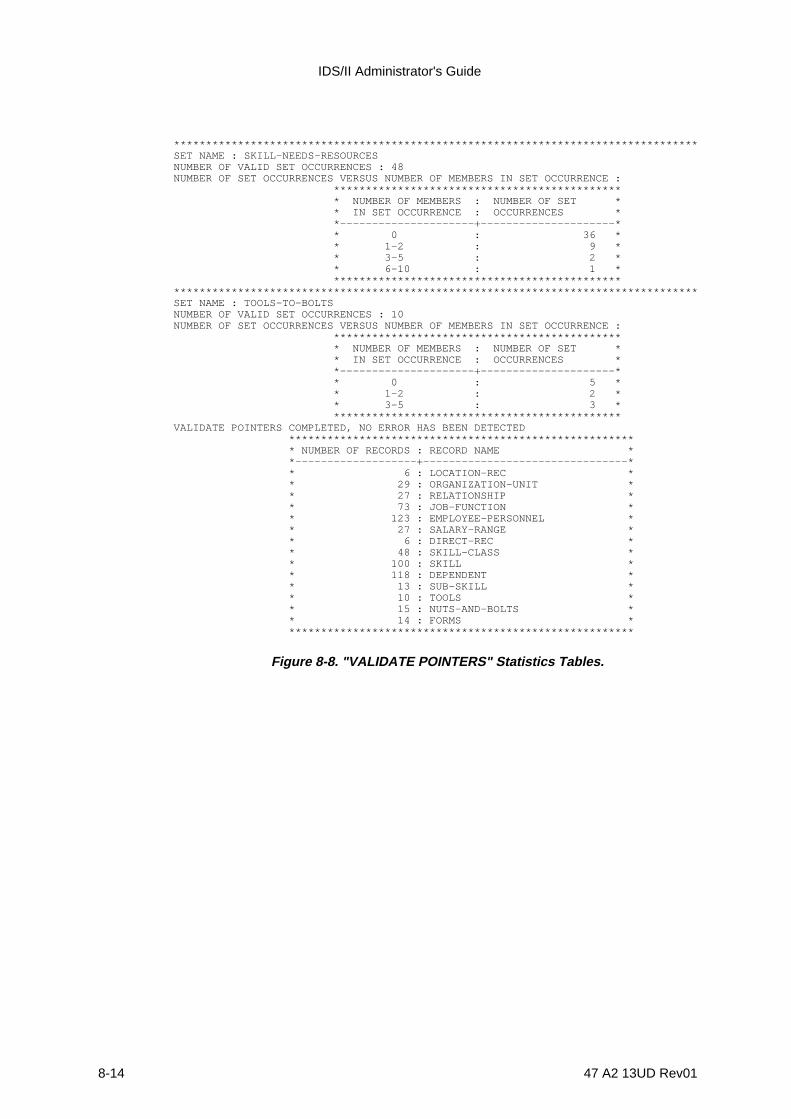
IDS/II Administrator's Guide
8-14 47 A2 13UD Rev01
**********************************************************************************SET NAME : SKILL-NEEDS-RESOURCESNUMBER OF VALID SET OCCURRENCES : 48NUMBER OF SET OCCURRENCES VERSUS NUMBER OF MEMBERS IN SET OCCURRENCE : ********************************************* * NUMBER OF MEMBERS : NUMBER OF SET * * IN SET OCCURRENCE : OCCURRENCES * *---------------------+---------------------* * 0 : 36 * * 1-2 : 9 * * 3-5 : 2 * * 6-10 : 1 * *******************************************************************************************************************************SET NAME : TOOLS-TO-BOLTSNUMBER OF VALID SET OCCURRENCES : 10NUMBER OF SET OCCURRENCES VERSUS NUMBER OF MEMBERS IN SET OCCURRENCE : ********************************************* * NUMBER OF MEMBERS : NUMBER OF SET * * IN SET OCCURRENCE : OCCURRENCES * *---------------------+---------------------* * 0 : 5 * * 1-2 : 2 * * 3-5 : 3 * *********************************************VALIDATE POINTERS COMPLETED, NO ERROR HAS BEEN DETECTED ****************************************************** * NUMBER OF RECORDS : RECORD NAME * *-------------------+--------------------------------* * 6 : LOCATION-REC * * 29 : ORGANIZATION-UNIT * * 27 : RELATIONSHIP * * 73 : JOB-FUNCTION * * 123 : EMPLOYEE-PERSONNEL * * 27 : SALARY-RANGE * * 6 : DIRECT-REC * * 48 : SKILL-CLASS * * 100 : SKILL * * 118 : DEPENDENT * * 13 : SUB-SKILL * * 10 : TOOLS * * 15 : NUTS-AND-BOLTS * * 14 : FORMS * ******************************************************
Figure 8-8. "VALIDATE POINTERS" Statistics Tables.

Database Validate and Patch Function
47 A2 13UD Rev01 8-15
8.4 VALIDATE PAGE COMMAND
8.4.1 Functions
1) to validate the UFAS page structure of one or several pages of a storage area,
2) to validate the IDS/II structure of the storage records contained in these pages,
3) optionally, to check that the IDS/II set pointers pointing outside of a validated pagelead to records participating in the same set occurrence.
8.4.2 General Format
{LOCALLY }VALIDATE PAGE { } {GLOBALLY }
[ AREA NAME IS area-name ]
[ {PAGE IS p} ... ][{ {PAGE p-1 THRU p-2 }} ][{ RANGE IS { }} ... ] {m PAGES FROM PAGE p-1 }} ]
8.4.3 Syntax Rules
1. p, p-1 and p-2 designate page numbers. They must be written as unsigned decimalintegers. Page numbers start from 0.
2. m designates a number of pages. It must be written as an unsigned decimal integerother than 0.
IDS/II Administrator's Guide
8-16 47 A2 13UD Rev01
8.4.4 General Rules
1. If LOCALLY is specified, the VALIDATE PAGE command checks:- the UFAS page structure,- the page header,- record locators,- storage record headers,- CALC chain information local to the page- the consistency of the set pointers of the storage records.
If a set pointer references a record located in the same page, VALIDATE PAGEchecks:- that the record pointed to actually exists,- that the record belongs to the same set occurrence (identified by the owner
data-base-key),- and that the record points back to the record containing the set pointer
validated.
2. If GLOBALLY is specified, the validation is performed in the same way as ifLOCALLY were specified, except that the check for records referenced by the setpointers found in the page is performed even if these records are located in otherpages of the same area or in a different area. If the records are in pages located inother areas, those areas must be assigned beforehand.
NOTE: The VALIDATE PAGE command does not check inter-page CALC-chaininformation.
3. The AREA Clause must be specified if the database is multi-area.
4. If the PAGE Clause is selected, the page validated is the one specified in the clause.
5. If the RANGE Clause is selected, the pages validated are those of the rangespecified. The range can be defined as either:- a number of pages between a first page number and a last page number. The
values are inclusive. The first page number must be less than or equal to thelast page number.
- or, a number of pages starting from a given page number. The range must fitinto the right-hand portion of the area. There is no possibility of wrap-around atthe end of the area.
6. Figures 8-9 and 8-10 provide sample reports of the VALIDATE PAGE command.
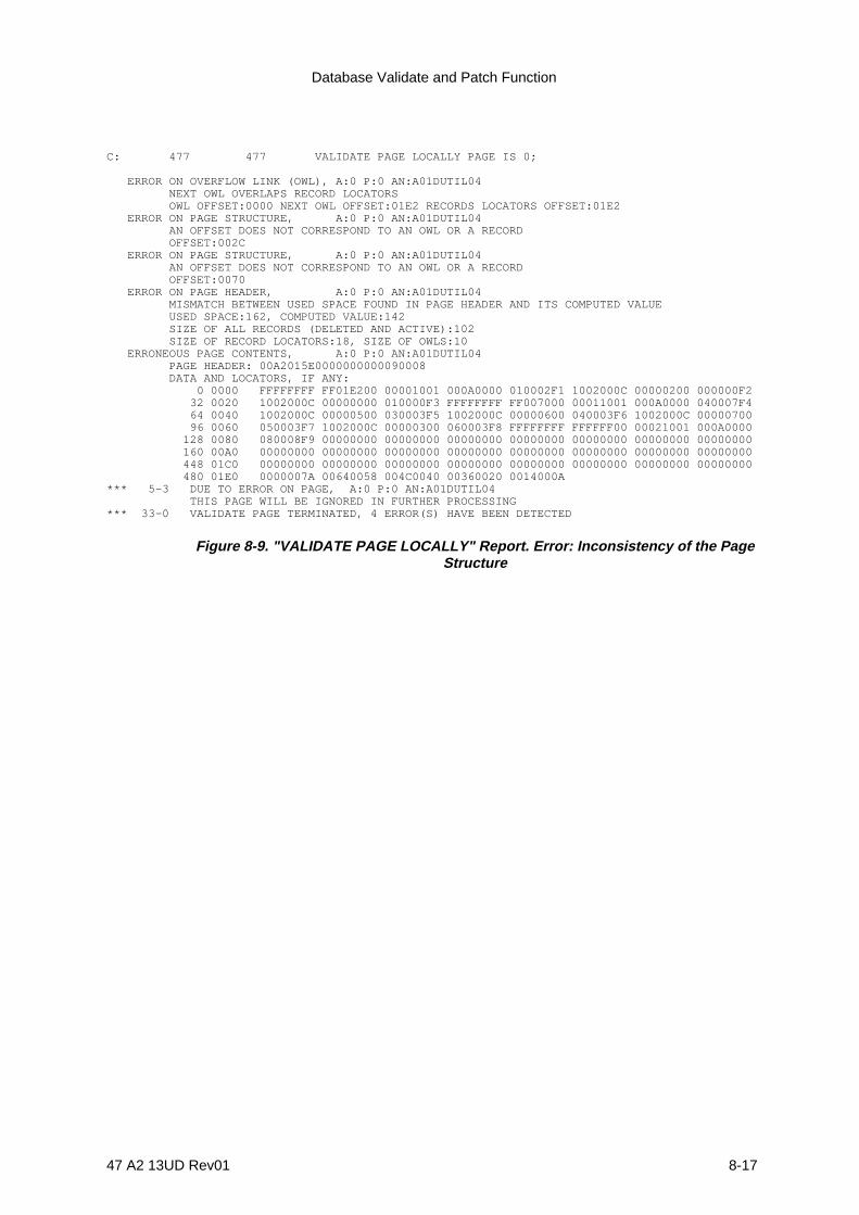
Database Validate and Patch Function
47 A2 13UD Rev01 8-17
C: 477 477 VALIDATE PAGE LOCALLY PAGE IS 0;
ERROR ON OVERFLOW LINK (OWL), A:0 P:0 AN:A01DUTIL04 NEXT OWL OVERLAPS RECORD LOCATORS OWL OFFSET:0000 NEXT OWL OFFSET:01E2 RECORDS LOCATORS OFFSET:01E2 ERROR ON PAGE STRUCTURE, A:0 P:0 AN:A01DUTIL04 AN OFFSET DOES NOT CORRESPOND TO AN OWL OR A RECORD OFFSET:002C ERROR ON PAGE STRUCTURE, A:0 P:0 AN:A01DUTIL04 AN OFFSET DOES NOT CORRESPOND TO AN OWL OR A RECORD OFFSET:0070 ERROR ON PAGE HEADER, A:0 P:0 AN:A01DUTIL04 MISMATCH BETWEEN USED SPACE FOUND IN PAGE HEADER AND ITS COMPUTED VALUE USED SPACE:162, COMPUTED VALUE:142 SIZE OF ALL RECORDS (DELETED AND ACTIVE):102 SIZE OF RECORD LOCATORS:18, SIZE OF OWLS:10 ERRONEOUS PAGE CONTENTS, A:0 P:0 AN:A01DUTIL04 PAGE HEADER: 00A2015E0000000000090008 DATA AND LOCATORS, IF ANY: 0 0000 FFFFFFFF FF01E200 00001001 000A0000 010002F1 1002000C 00000200 000000F2 32 0020 1002000C 00000000 010000F3 FFFFFFFF FF007000 00011001 000A0000 040007F4 64 0040 1002000C 00000500 030003F5 1002000C 00000600 040003F6 1002000C 00000700 96 0060 050003F7 1002000C 00000300 060003F8 FFFFFFFF FFFFFF00 00021001 000A0000 128 0080 080008F9 00000000 00000000 00000000 00000000 00000000 00000000 00000000 160 00A0 00000000 00000000 00000000 00000000 00000000 00000000 00000000 00000000 448 01C0 00000000 00000000 00000000 00000000 00000000 00000000 00000000 00000000 480 01E0 0000007A 00640058 004C0040 00360020 0014000A*** 5-3 DUE TO ERROR ON PAGE, A:0 P:0 AN:A01DUTIL04 THIS PAGE WILL BE IGNORED IN FURTHER PROCESSING*** 33-0 VALIDATE PAGE TERMINATED, 4 ERROR(S) HAVE BEEN DETECTED
Figure 8-9. "VALIDATE PAGE LOCALLY" Report. Error: Inconsistency of the PageStructure
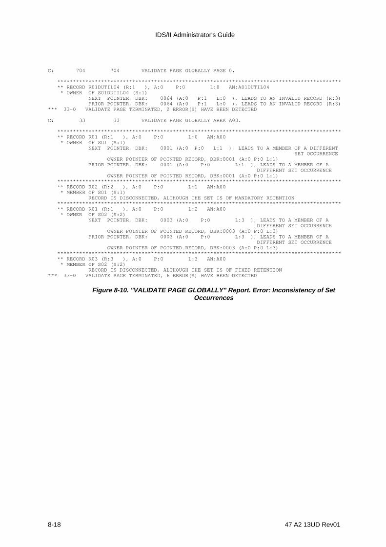
IDS/II Administrator's Guide
8-18 47 A2 13UD Rev01
C: 704 704 VALIDATE PAGE GLOBALLY PAGE 0.
******************************************************************************************* ** RECORD R01DUTIL04 (R:1 ), A:0 P:0 L:8 AN:A01DUTIL04 * OWNER OF S01DUTIL04 (S:1) NEXT POINTER, DBK: 0064 (A:0 P:1 L:0 ), LEADS TO AN INVALID RECORD (R:3) PRIOR POINTER, DBK: 0064 (A:0 P:1 L:0 ), LEADS TO AN INVALID RECORD (R:3)*** 33-0 VALIDATE PAGE TERMINATED, 2 ERROR(S) HAVE BEEN DETECTED
C: 33 33 VALIDATE PAGE GLOBALLY AREA A00.
******************************************************************************************* ** RECORD R01 (R:1 ), A:0 P:0 L:0 AN:A00 * OWNER OF S01 (S:1) NEXT POINTER, DBK: 0001 (A:0 P:0 L:1 ), LEADS TO A MEMBER OF A DIFFERENT SET OCCURRENCE OWNER POINTER OF POINTED RECORD, DBK:0001 (A:0 P:0 L:1) PRIOR POINTER, DBK: 0001 (A:0 P:0 L:1 ), LEADS TO A MEMBER OF A DIFFERENT SET OCCURRENCE OWNER POINTER OF POINTED RECORD, DBK:0001 (A:0 P:0 L:1) ******************************************************************************************* ** RECORD R02 (R:2 ), A:0 P:0 L:1 AN:A00 * MEMBER OF S01 (S:1) RECORD IS DISCONNECTED, ALTHOUGH THE SET IS OF MANDATORY RETENTION ******************************************************************************************* ** RECORD R01 (R:1 ), A:0 P:0 L:2 AN:A00 * OWNER OF S02 (S:2) NEXT POINTER, DBK: 0003 (A:0 P:0 L:3 ), LEADS TO A MEMBER OF A DIFFERENT SET OCCURRENCE OWNER POINTER OF POINTED RECORD, DBK:0003 (A:0 P:0 L:3) PRIOR POINTER, DBK: 0003 (A:0 P:0 L:3 ), LEADS TO A MEMBER OF A DIFFERENT SET OCCURRENCE OWNER POINTER OF POINTED RECORD, DBK:0003 (A:0 P:0 L:3) ******************************************************************************************* ** RECORD R03 (R:3 ), A:0 P:0 L:3 AN:A00 * MEMBER OF S02 (S:2) RECORD IS DISCONNECTED, ALTHOUGH THE SET IS OF FIXED RETENTION*** 33-0 VALIDATE PAGE TERMINATED, 6 ERROR(S) HAVE BEEN DETECTED
Figure 8-10. "VALIDATE PAGE GLOBALLY" Report. Error: Inconsistency of SetOccurrences

Database Validate and Patch Function
47 A2 13UD Rev01 8-19
8.5 VALIDATE CALC-CHAINS COMMAND
8.5.1 Function
1) to validate CALC chains within one or more areas.
2) to validate the UFAS page structure of all the pages of the areas involved.
For a CALC-chain, this command checks the following:
- that the CALC chain is not broken,
- that there is no cycle, that only the head-of-bucket could be the beginning of aCALC chain.
For each record of a CALC chain, the actual HASH-code is checked to obtatin thecorrect value.
8.5.2 General Format
VALIDATE CALC-CHAINS
[AREA NAME IS area-name ][STOP AFTER integer ERRORS]
8.5.3 General Rules
1. The AREA Clause must be specified if the database is multi-area.
2. The STOP ... ERRORS Clause directs the processing to be ceased after a certainnumber of errors.
3. If the STOP .T.. ERRORS Clause is not specified, processing continues regardlessof the number of errors detected.

IDS/II Administrator's Guide
8-20 47 A2 13UD Rev01
8.5.4 Interpretation of the VALIDATE CALC-CHAINS Report
The extracts from reports, shown in Figures 8-11 to 8-16, correspond to a database inwhich errors have been introduced by patching the contents of pages.
They illustrate the format which is output to SYSOUT or on the terminal.
The report contains in two phases:
1) a check at the page level,
2) and, a check at the area level.
Both these phases are explained below:
• The check at page level examines any inconsistency other than an incorrect hashcode.When an inconsistency is detected, the contents of the page are dumped and the pageis ignored in future processing. If the inconsistency is an incorrect hashcode, anidentification of the record and the correct hashcode are displayed.
• The check at area level examines the connection between OWL's. Error messages aregrouped by CALC-chain occurrences identified by the identification of the ROOT.

Database Validate and Patch Function
47 A2 13UD Rev01 8-21
C: VALIDATE CALC-CHAIN;
X,Y OWL page X rank Y
pointer to next OWL of calc-chain
po in ter to the Root of calc-chain
OWL page X rank Y missing
****************************************************************************************
C ALC -C H AIN O C C U R R EN C E ID EN TIF IE D BY O W L (A :0 P :15 R :0) - O W L (P :15 R :0 ) H EAD O F C ALC -C H AIN M IS SIN G C R IN A C TIVE - TH ER E IS N O O W L PO IN TIN G TO O W L (P :16 R :0) IN C U R R EN T C ALC -C H AINO C C U R R EN C E
X,Y
15,0 16,0 17,0
Figure 8-11. "VALIDATE CALC-CHAIN" report. Error: Root missing in a calc-chain occurrence

IDS/II Administrator's Guide
8-22 47 A2 13UD Rev01
C: VALIDATE CALC-CHAIN;
X,Y OWL page X rank Y
pointer to next OWL of calc-chain
po in ter to the Root o f calc-chain
OWL page X rank Y missing
****************************************************************************************
X,Y
0.0 1.0 2.0
C A LC _-C H AIN O C C U R R EN C E ID EN TIF IED BY O W L (A :0 P :0 R :0 )- O W L (P :0 R :0) H EAD O F C ALC -C H AIN M ISSIN G O R IN AC TIVE- TH ER E IS N O O W L PO IN TIN G TO O W L (P :0 R :0) IN C U R R EN T C ALC -C H AIN O C C U R R EN C E
Figure 8-12. "VALIDATE CALC-CHAIN" Report. Error: OWL missing ina calc-chain occurrence

Database Validate and Patch Function
47 A2 13UD Rev01 8-23
C: VALIDATE CALC-CHAIN;
X,Y OWL page X rank Y
pointer to next OWL of calc-chain
po in ter to the Root o f calc-chain
****************************************************************************************
C AL C -C H AIN O C C U R R EN C E ID EN T IF IED BY O W L (A :0 P :13 5 R :0 )-O W L (P :1 5 5 R :2) L EA D S T O O W L (P :1 35 R :0 ) H EAD O F C AL C -C H AIN O C C U R R EN C E-O W L (P :1 3 5 R :0) A N D O W L (P :1 4 0 R :1) A R E PO IN T IN G T O T H E SAM E O W L (P :1 36 P :0 )-T H ER E IS N O O W L P O IN T IN G T O O W L (P :14 0 R :1 ) IN C U R R EN T C AL C -C H AIN O C C U R R EN C E-T H ER E IS N O O W L P O IN T IN G T O O W L (P :14 3 R :1 ) IN C U R R EN T C AL C -C H AIN O C C U R R EN C E-O W L (P :1 3 7 R :0) A N D O W L (P :1 4 6 R :3) A R E PO IN T IN G T O T H E SAM E O W L (P :1 49 R :3 )-T H ER E IS N O O W L P O IN T IN G T O O W L (P :18 2 R :1 ) IN C U R R EN T C AL C -C H AIN O C C U R R EN C E
135.0 136.0 137.0 140.1 143.1 146.3 149.3 155.2 182.1
Figure 8-13. "VALIDATE CALC-CHAIN " Report. Error: Next OWL is incorrect in a calc-chainoccurrence
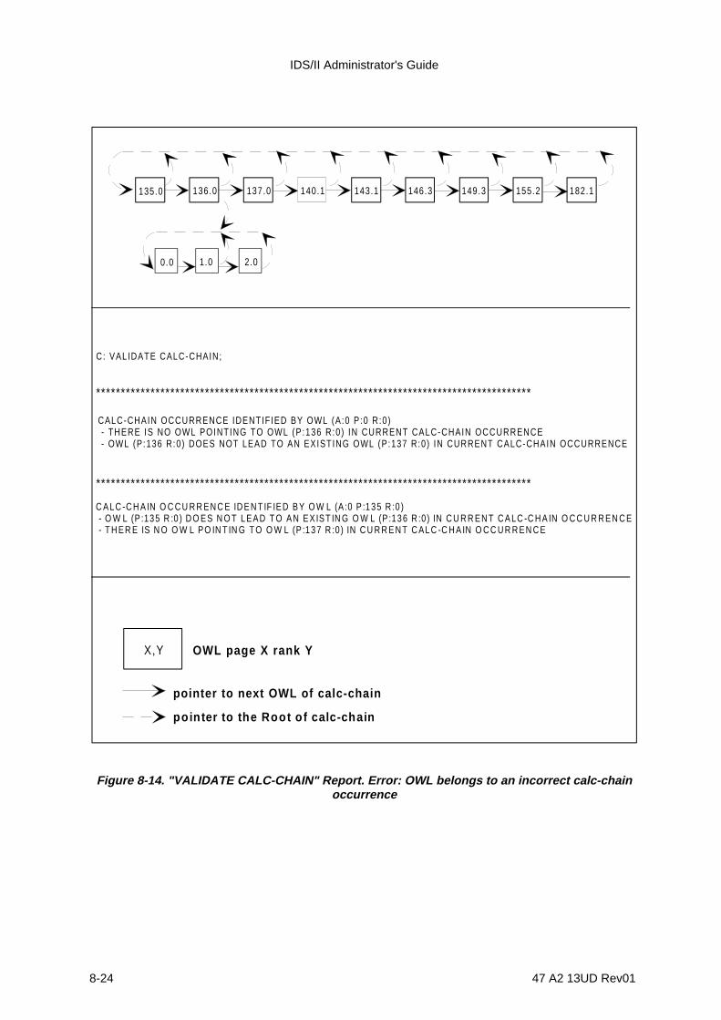
IDS/II Administrator's Guide
8-24 47 A2 13UD Rev01
C: VALIDATE CALC-CHAIN;
X,Y OWL page X rank Y
pointer to next OWL of calc-chain
po in ter to the Root o f calc-chain
****************************************************************************************
135.0 136.0 137.0 140.1 143.1 146.3 149.3
0.0 1.0 2.0
CALC-CHAIN OCCURRENCE IDENTIFIED BY OWL (A:0 P :0 R:0) - THERE IS NO OWL POINTING TO OWL (P :136 R:0 ) IN CURRENT CALC-CHAIN OCCURRENCE - OWL (P:136 R:0) DOES NOT LEAD TO AN EXISTING OWL (P:137 R:0) IN CURRENT CALC-CHAIN OCCURRENCE
C AL C -C H AIN O C C U R R E N C E ID E N T IF IE D B Y O W L (A :0 P :1 3 5 R :0 ) - O W L (P :135 R :0 ) D O ES N O T LEAD T O AN EX IST IN G O W L (P :136 R :0) IN C U R R EN T C A LC -C H A IN O C C U R R EN C E - T H ER E IS N O O W L PO IN T IN G T O O W L (P :1 3 7 R :0) IN C U R R EN T C AL C -C H A IN O C C U R R EN C E
****************************************************************************************
155.2 182.1
Figure 8-14. "VALIDATE CALC-CHAIN" Report. Error: OWL belongs to an incorrect calc-chainoccurrence
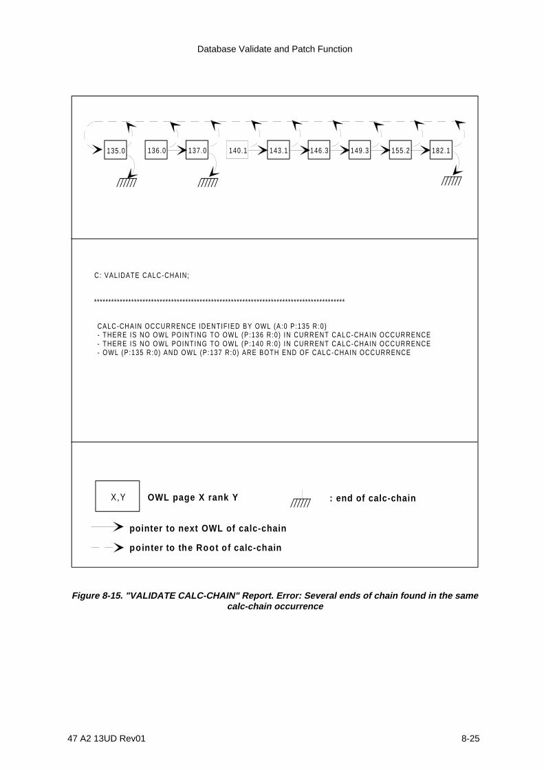
Database Validate and Patch Function
47 A2 13UD Rev01 8-25
C: VALIDATE CALC-CHAIN;
X,Y OWL page X rank Y
pointer to next OWL of calc-chain
po inter to the Root o f calc-chain
****************************************************************************************
135.0 136.0 137.0 140.1 143.1 146.3 149.3 155.2 182.1
CALC-CHAIN OCCURRENCE IDENTIFIED BY OWL (A:0 P :135 R:0)- THERE IS NO OWL POINTING TO OWL (P :136 R:0 ) IN CURRENT CALC-CHAIN OCCURRENCE- THERE IS NO OWL POINTING TO OWL (P :140 R:0 ) IN CURRENT CALC-CHAIN OCCURRENCE- OWL (P :135 R:0) AND OWL (P :137 R:0) ARE BOTH END OF CALC-CHAIN OCCURRENCE
: end of calc-chain
Figure 8-15. "VALIDATE CALC-CHAIN" Report. Error: Several ends of chain found in the samecalc-chain occurrence

IDS/II Administrator's Guide
8-26 47 A2 13UD Rev01
C: VALIDATE CALC-CHAIN;
X,Y OWL page X rank Y
pointer to next OWL of calc-chain
po in ter to the Root o f calc-chain
****************************************************************************************
135.0 136.0 137.0 140.1 143.1 146.3 149.3
0.0 1.0 2.0
****************************************************************************************
155.2 182.1
CALC-CHAIN OCCURRENCE IDENTIFIED BY OWL (A:0 P :135 R:0)- OWL (P :182 R:1) DOES NOT LEAD TO AN EXISTING OWL (P :1 R:0) IN CURRENT CALC-CHAIN OCCURRENCE- END OF CALC-CHAIN HAS NOT BEEN FOUND
CALC-CHAIN OCCURRENCE IDENTIFIED BY OWL (A:0 P :135 R:0)- OWL (P :135 R:0) DOES NOT LEAD TO AN EXISTING OWL (P :136 R:0) IN CURRENT CALC-CHAIN OCCURRENCE- THERE IS NO OWL POINTING TO OWL (P :137 R:0 ) IN CURRENT CALC-CHAIN OCCURRENCE
Figure 8-16. "VALIDATE CALC-CHAIN" Report. Error: End of calc-chain not found and followingOWL is in a wrong calc-chain occurrence
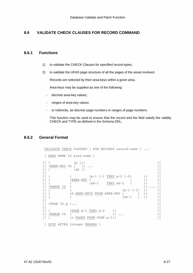
Database Validate and Patch Function
47 A2 13UD Rev01 8-27
8.6 VALIDATE CHECK CLAUSES FOR RECORD COMMAND
8.6.1 Functions
1) to validate the CHECK Clauses for specified record-types,
2) to validate the UFAS page structure of all the pages of the areas involved.
Records are selected by their area-keys within a given area.
Area-keys may be supplied as one of the following:
- discrete area-key values,
- ranges of area-key values
- or indirectly, as discrete page numbers or ranges of page numbers.
This function may be used to ensure that the record and the field satisfy the validityCHECK and TYPE as defined in the Schema DDL.
8.6.2 General Format
VALIDATE CHECK CLAUSES [ FOR RECORDS record-name ] ...
[ AREA NAME IS area-name ]
[{ { {p l}} }][{ {AREA-KEY IS { }} ... }][{ { {ak }} }][{ }][{ { { {p-1 l-1 THRU p-2 l-2} }} }][{ { {AREA-KEY { } }} }][{ { { {ak-1 THRU ak-2 } }} }][{ {RANGE IS { }} ... }][{ { { {p-1 l-1} }} }][{ { {m AREA-KEYS FROM AREA-KEY { } }} }][{ { { {ak-1 } }} }][{ }][{ {PAGE IS p }... }][{ }][{ { {PAGE p-1 THRU p-2 }} }][{ {RANGE IS { }} ... }][{ { {n PAGES FROM PAGE p-1}} }]
[ STOP AFTER integer ERRORS ]
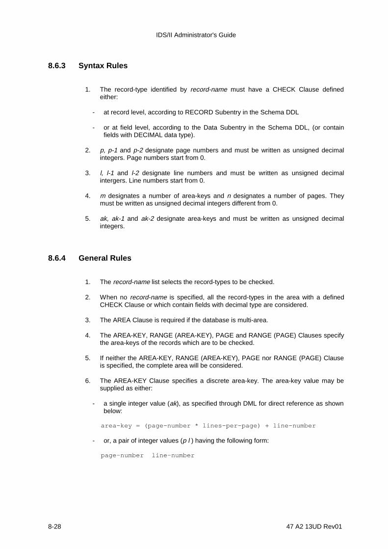
IDS/II Administrator's Guide
8-28 47 A2 13UD Rev01
8.6.3 Syntax Rules
1. The record-type identified by record-name must have a CHECK Clause definedeither:
- at record level, according to RECORD Subentry in the Schema DDL
- or at field level, according to the Data Subentry in the Schema DDL, (or containfields with DECIMAL data type).
2. p, p-1 and p-2 designate page numbers and must be written as unsigned decimalintegers. Page numbers start from 0.
3. l, l-1 and l-2 designate line numbers and must be written as unsigned decimalintergers. Line numbers start from 0.
4. m designates a number of area-keys and n designates a number of pages. Theymust be written as unsigned decimal integers different from 0.
5. ak, ak-1 and ak-2 designate area-keys and must be written as unsigned decimalintegers.
8.6.4 General Rules
1. The record-name list selects the record-types to be checked.
2. When no record-name is specified, all the record-types in the area with a definedCHECK Clause or which contain fields with decimal type are considered.
3. The AREA Clause is required if the database is multi-area.
4. The AREA-KEY, RANGE (AREA-KEY), PAGE and RANGE (PAGE) Clauses specifythe area-keys of the records which are to be checked.
5. If neither the AREA-KEY, RANGE (AREA-KEY), PAGE nor RANGE (PAGE) Clauseis specified, the complete area will be considered.
6. The AREA-KEY Clause specifies a discrete area-key. The area-key value may besupplied as either:
- a single integer value (ak), as specified through DML for direct reference as shownbelow:
area-key = (page-number * lines-per-page) + line-number
- or, a pair of integer values (p l ) having the following form:
page-number line-number
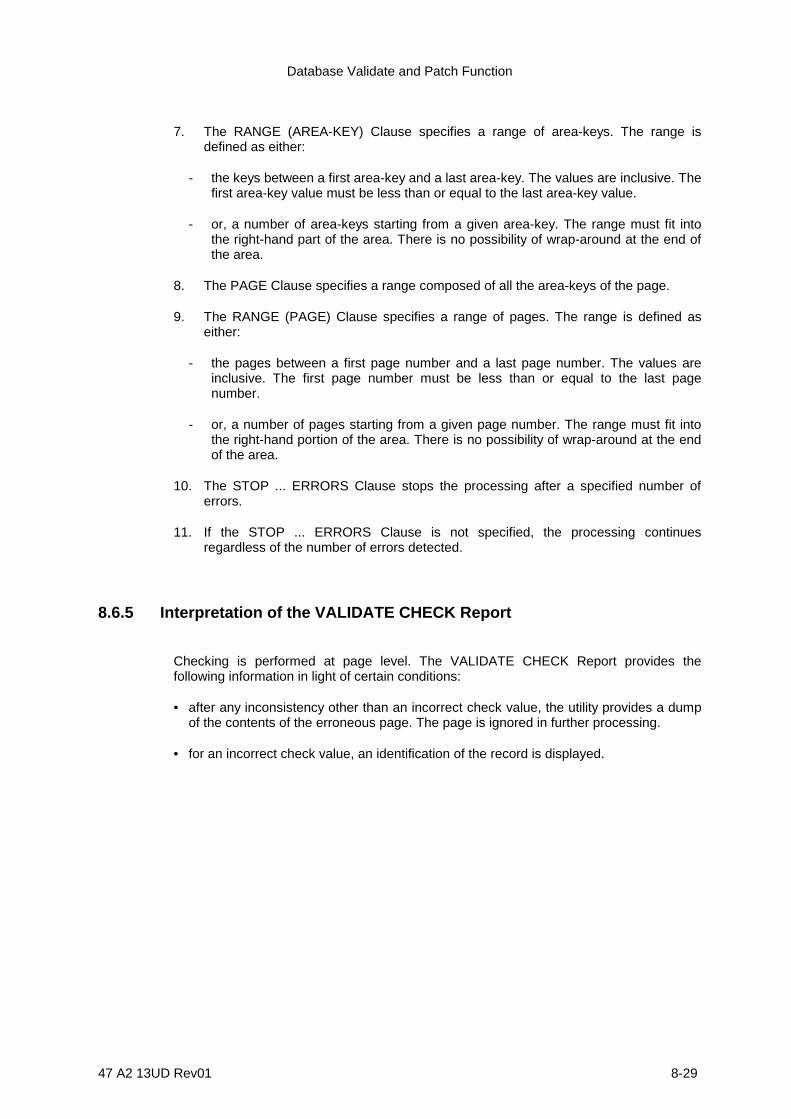
Database Validate and Patch Function
47 A2 13UD Rev01 8-29
7. The RANGE (AREA-KEY) Clause specifies a range of area-keys. The range isdefined as either:
- the keys between a first area-key and a last area-key. The values are inclusive. Thefirst area-key value must be less than or equal to the last area-key value.
- or, a number of area-keys starting from a given area-key. The range must fit intothe right-hand part of the area. There is no possibility of wrap-around at the end ofthe area.
8. The PAGE Clause specifies a range composed of all the area-keys of the page.
9. The RANGE (PAGE) Clause specifies a range of pages. The range is defined aseither:
- the pages between a first page number and a last page number. The values areinclusive. The first page number must be less than or equal to the last pagenumber.
- or, a number of pages starting from a given page number. The range must fit intothe right-hand portion of the area. There is no possibility of wrap-around at the endof the area.
10. The STOP ... ERRORS Clause stops the processing after a specified number oferrors.
11. If the STOP ... ERRORS Clause is not specified, the processing continuesregardless of the number of errors detected.
8.6.5 Interpretation of the VALIDATE CHECK Report
Checking is performed at page level. The VALIDATE CHECK Report provides thefollowing information in light of certain conditions:
• after any inconsistency other than an incorrect check value, the utility provides a dumpof the contents of the erroneous page. The page is ignored in further processing.
• for an incorrect check value, an identification of the record is displayed.
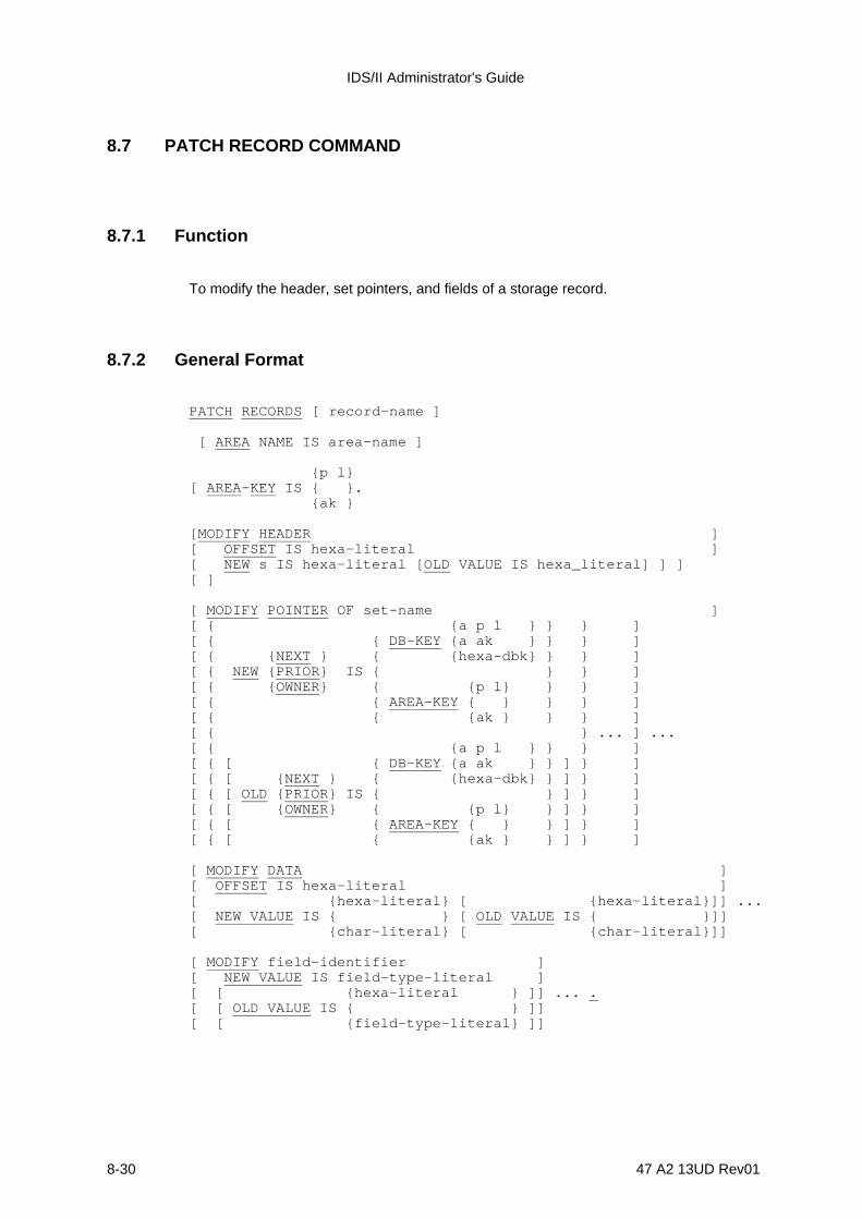
IDS/II Administrator's Guide
8-30 47 A2 13UD Rev01
8.7 PATCH RECORD COMMAND
8.7.1 Function
To modify the header, set pointers, and fields of a storage record.
8.7.2 General Format
PATCH RECORDS [ record-name ]
[ AREA NAME IS area-name ]
{p l}[ AREA-KEY IS { }. {ak }
[MODIFY HEADER ][ OFFSET IS hexa-literal ][ NEW s IS hexa-literal [OLD VALUE IS hexa_literal] ] ][ ]
[ MODIFY POINTER OF set-name ][ { {a p l } } } ][ { { DB-KEY {a ak } } } ][ { {NEXT } { {hexa-dbk} } } ][ { NEW {PRIOR } IS { } } ][ { {OWNER} { {p l} } } ][ { { AREA-KEY { } } } ][ { { {ak } } } ][ { } ... ] ...[ { {a p l } } } ][ { [ { DB-KEY {a ak } } ] } ][ { [ {NEXT } { {hexa-dbk} } ] } ][ { [ OLD {PRIOR } IS { } ] } ][ { [ {OWNER} { {p l} } ] } ][ { [ { AREA-KEY { } } ] } ][ { [ { {ak } } ] } ]
[ MODIFY DATA ][ OFFSET IS hexa-literal ][ {hexa-literal} [ {hexa-literal}]] ...[ NEW VALUE IS { } [ OLD VALUE IS { }]][ {char-literal} [ {char-literal}]]
[ MODIFY field-identifier ][ NEW VALUE IS field-type-literal ][ [ {hexa-literal } ]] ... .[ [ OLD VALUE IS { } ]][ [ {field-type-literal} ]]
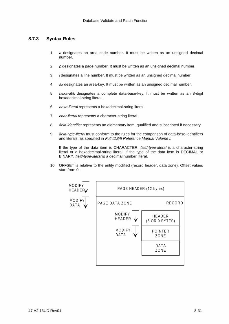
Database Validate and Patch Function
47 A2 13UD Rev01 8-31
8.7.3 Syntax Rules
1. a designates an area code number. It must be written as an unsigned decimalnumber.
2. p designates a page number. It must be written as an unsigned decimal number.
3. l designates a line number. It must be written as an unsigned decimal number.
4. ak designates an area-key. It must be written as an unsigned decimal number.
5. hexa-dbk designates a complete data-base-key. It must be written as an 8-digithexadecimal-string literal.
6. hexa-literal represents a hexadecimal-string literal.
7. char-literal represents a character-string literal.
8. field-identifier represents an elementary item, qualified and subscripted if necessary.
9. field-type-literal must conform to the rules for the comparison of data-base-identifiersand literals, as specified in Full IDS/II Reference Manual Volume I.
If the type of the data item is CHARACTER, field-type-literal is a character-stringliteral or a hexadecimal-string literal. If the type of the data item is DECIMAL orBINARY, field-type-literal is a decimal number literal.
10. OFFSET is relative to the entity modified (record header, data zone). Offset valuesstart from 0.
MODIFYHEADER PAGE HEADER (12 bytes)
PAGE DATA ZONE
MODIFYHEADER
MODIFYDATA
MODIFYDATA
HEADER(5 OR 9 BYTES)
POINTERZONE
DATAZONE
R E C O R D

IDS/II Administrator's Guide
8-32 47 A2 13UD Rev01
8.7.4 General Rules
1. If record-name is specified in the PATCH RECORD command, the record to bepatched is checked to make sure it is of the specified record-type.
2. The AREA Clause must be specified if the database is multi area.
3. The AREA-KEY Clause specifies the area-key of the record to be patched. The area-key value can be defined as either:
- a page number and a line number,
- or, an area-key ak = p * LPP + l where LPP is the number of lines per page.
4. The MODIFY HEADER Clause allows the modification of a byte string of the storagerecord header. The leftmost byte of the string is defined by the OFFSET phrase,which specifies an offset relative to the beginning of the header.
The length of the byte string is defined by the byte length of the hexadecimal-stringliteral which is specified in the NEW VALUE phrase. The new contents of the bytestring are specified in the NEW VALUE phrase.
If the OLD VALUE phrase is specified (which is recommended), the old contents arechecked to be those specified. In case of mismatch, the modification does not occur.The OLD VALUE hexadecimal-string literal must have the same length as the NEWVALUE hexadecimal-string literal.
5. The MODIFY POINTER Clause allows the modification of the NEXT/PRIOR/OWNER pointers of the set set-name within the storage record.
Pointer values can be supplied as either data-base-keys, if pointers are global orlocal, or as area-keys if pointers are local.
Data-base-key values are defined as follows:
- an area code number, a page number and a line number,
- an area code number and an area-key ak = p * LPP + l, or
- a complete data-base-key in hexadecimal format.
Area-key values are defined as either:
- a page number and a line number, or
- an area-key ak = p * LPP + l.
The new pointer value is given in the NEW VALUE phrase. If the OLD VALUEphrase is specified, the old contents are checked to be those specified.
Database Validate and Patch Function
47 A2 13UD Rev01 8-33
6. The MODIFY DATA Clause allows the modification of a byte string within the datazone of the storage record header.
The leftmost byte of the string is defined by the OFFSET phrase, which specifies anoffset relative to the beginning of the data zone. The length of the byte string isdefined by the byte length of the literal specified in the NEW VALUE phrase. Thislength cannot exceed 256.
The new contents of the byte string are specified in the NEW VALUE phrase. If theOLD VALUE phrase is specified, the old contents are checked to be those specified.The OLD VALUE literal and the NEW VALUE literal must have the same length.
7. The MODIFY field-identifier Clause allows the modification of a data item of thestorage record.
The new contents of the field are specified in the NEW VALUE phrase. If the OLDVALUE phrase is specified, the old contents are checked to be those specified.
For fields of type CHARACTER, the length of the OLD VALUE literal may be lessthan the length of the field. In this case, right padding with spaces is assumed. Forfields of type BINARY and DECIMAL, the length of the OLD VALUE hexadecimalstring literal must be equal to the length of the field.
Since the byte length of a literal cannot exceed 256, the MODIFY DATA Clauses arenecessary for longer fields.
8. The PATCH command is in fact a sequence of MODIFY sub-commands. These sub-commands are analyzed and executed sequentially, which brings about the followingresults:
- The new contents applied by a sub-command may become the old contentsreferenced by a subsequent sub-command.
- When a sub-command is erroneous, the PATCH command is interrupted but themodification applied by the previous sub-commands are not cancelled.
9. The PATCH RECORD command assumes that the page structure (header, locators)provides enough information to access the record by using its line number. If thepage structure is corrupted, you should use the PATCH PAGE command.
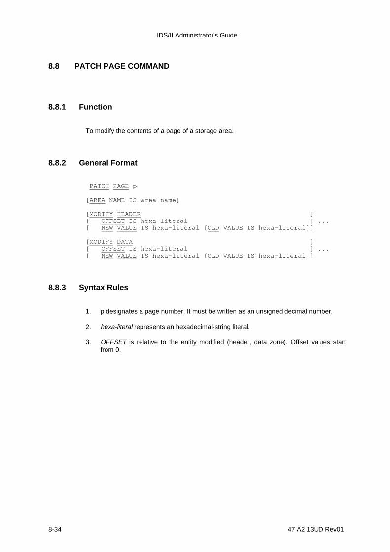
IDS/II Administrator's Guide
8-34 47 A2 13UD Rev01
8.8 PATCH PAGE COMMAND
8.8.1 Function
To modify the contents of a page of a storage area.
8.8.2 General Format
PATCH PAGE p
[AREA NAME IS area-name]
[MODIFY HEADER ][ OFFSET IS hexa-literal ] ...[ NEW VALUE IS hexa-literal [OLD VALUE IS hexa-literal]]
[MODIFY DATA ][ OFFSET IS hexa-literal ] ...[ NEW VALUE IS hexa-literal [OLD VALUE IS hexa-literal ]
8.8.3 Syntax Rules
1. p designates a page number. It must be written as an unsigned decimal number.
2. hexa-literal represents an hexadecimal-string literal.
3. OFFSET is relative to the entity modified (header, data zone). Offset values startfrom 0.

Database Validate and Patch Function
47 A2 13UD Rev01 8-35
8.8.4 General Rules
1. The page to be patched is specified in the PATCH PAGE Clause by giving its pagenumber (p).
2. The AREA Clause must be specified if the database is multi-area.
3. The MODIFY HEADER Clause allows the modification of a byte string of the pageheader. The desired modification should not affect the PAGE-NUMBER value.
The leftmost byte of the string is defined by the OFFSET phrase, which specifies anoffset relative to the beginning of the header. The length of the byte string is definedby the byte length of the hexadecimal-string literal specified in the NEW VALUEphrase.
The new contents of the byte string are specified in the NEW VALUE phrase. If theOLD VALUE phrase is specified, the old contents are checked to be those specified.In case of mismatch, the modification does not occur. The OLD VALUEhexadecimal-string literal must have the same length as the NEW VALUEhexadecimal-string literal.
4. The MODIFY DATA Clause allows the modification of a byte string within the datazone of the page.
The leftmost byte of the string is defined by the OFFSET phrase, which specifies anoffset relative to the beginning of the data zone. The length of the byte string isdefined by the byte length of the hexadecimal-string literal specified in the NEWVALUE phrase. This length cannot exceed 256.
The new contents of the byte string are specified in the NEW VALUE phrase. If theOLD VALUE phrase is specified, the old contents are checked to be those specified.The OLD VALUE hexadecimal-string literal and the NEW VALUE hexadecimal-stringliteral must have the same length.
5. The PATCH command is a sequence of MODIFY sub-commands. These sub-commands are analyzed and executed sequentially, which yields the followingresults:
- New contents applied by a sub-command may become the old contents referencedby a subsequent sub-command.
- If a sub-command contains errors, the PATCH command is interrupted but themodifications applied by the previous sub-commands are not cancelled.
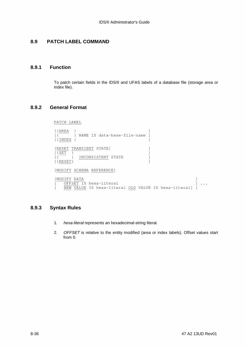
IDS/II Administrator's Guide
8-36 47 A2 13UD Rev01
8.9 PATCH LABEL COMMAND
8.9.1 Function
To patch certain fields in the IDS/II and UFAS labels of a database file (storage area orindex file).
8.9.2 General Format
PATCH LABEL
[{AREA } ][{ } NAME IS data-base-file-name ][{INDEX } ]
[RESET TRANSIENT STATE] ][{SET } ][{ } INCONSISTENT STATE ][{RESET} ]
[MODIFY SCHEMA REFERENCE]
[MODIFY DATA ][ OFFSET IS hexa-literal ] ...[ NEW VALUE IS hexa-literal OLD VALUE IS hexa-literal] ]
8.9.3 Syntax Rules
1. hexa-literal represents an hexadecimal-string literal.
2. OFFSET is relative to the entity modified (area or index labels). Offset values startfrom 0.

Database Validate and Patch Function
47 A2 13UD Rev01 8-37
8.9.4 General Rules
1. data-base-file-name must be specified if the database is multi-file.
2. The RESET TRANSIENT Clause resets the TRANSIENT STATE flag of the UFASlabel.
3. The SET/RESET INCONSISTENT Clause sets or resets the INCONSISTENTSTATE flag of the IDS label.
4. The MODIFY SCHEMA REFERENCE Clause modifies the schema name, theDMCL reference date and the file name (or area or index name) of the IDS/II label,making them correspond to those of the loaded schema.
When this clause is specified, no checks are performed on the schema name, theDMCL reference date, or the file name of the IDS label prior to the modification. Thefile name specified by data-base-file-name must be the name defined in the loadedschema.
The MODIFY Clause does not allow a modification of the physical characteristics ofthe file (number of pages, page size, lines per page, CALC-interval). Thesecharacteristics are checked against those of the loaded schema.
5. The MODIFY DATA Clause allows the modification of a byte string within thecontents of the labels. The leftmost byte of the string is defined by the OFFSETphrase, which specifies an offset relative to the beginning of the label zone. Thelength of the byte string is defined by the byte length of the hexadecimal-string literalspecified in the NEW VALUE phrase. This length cannot exceed 256.
The new contents of the byte string are specified in the NEW VALUE phrase. If theOLD VALUE phrase is specified, the old contents are checked to be those specified.
The OLD VALUE hexadecimal-string literal and the NEW VALUE hexadecimal-stringliteral must have the same length.

IDS/II Administrator's Guide
8-38 47 A2 13UD Rev01
8.10 RECONNECT RECORD COMMAND
8.10.1 Function
To reconnect CALC records of one or more types to their correct CALC chains, accordingto the values of their CALC-keys. The records are selected by area-key within a givenarea.
Area-keys may be supplied as one of the following:
• discrete area-key values,• ranges of area-key values• or, indirectly as discrete page numbers or ranges of page numbers.
The RECONECT Record command can be used when certain CALC records are nolonger connected to their correct CALC chains. This can be due to a databaseinconsistency or a change in their CALC-key description after the storage of theserecords.
8.10.2 General Format
RECONNECT RECORD [record-name] ... TO CALC-CHAIN
[AREA NAME IS area-name ]
[{ { {p l}} }][{ {AREA-KEY IS { }} ... }][{ { {ak }} }][{ { {p-1 l-1 THRU p-2 l-2 } }} }][{ {AREA-KEY { } }} }][{ { {ak-1 THRU ak-2 } }} }][{RANGE IS { }} ... }][{ { {p-1 l-1} }} }][{ {m AREA-KEYS FROM AREA-KEY { } }} }][{ { {ak-1 } }} }][{ }][{ {PAGE IS p }... }][{{ {PAGE p-1 THRU p-2 }} }][{{RANGE IS { }} ... }][{{ {n PAGES FROM PAGE p-1}} }]
[STOP AFTER integer ERRORS ]
Database Validate and Patch Function
47 A2 13UD Rev01 8-39
8.10.3 Syntax Rules
1. The record-type identified by record-name must have a CALC location mode.
2. p, p-1 and p-2 designate page numbers and must be written as unsigned decimalintegers. Page numbers start from 0.
3. l, l-1 and l-2 designate line numbers and must be written as unsigned decimalintergers. Line numbers start from 0.
4. m designates a number of area-keys and n designates a number of pages. Theymust be written as unsigned decimal integers different from 0.
5. ak, ak-1 and ak-2 designate area-keys and must be written as unsigned decimalintegers.
8.10.4 General Rules
1. The record-name list selects the record-types to be reconnected.
2. When no record-name is specified, all the record-types of CALC records areconsidered in the area.
3. The AREA Clause is required if the database is multi-area.
4. The AREA-KEY, RANGE (AREA-KEY), PAGE and RANGE (PAGE) Clauses specifythe area-keys of the records to be reconnected.
5. If neither the AREA-KEY, RANGE (AREA-KEY), PAGE, nor RANGE (PAGE) Clauseis specified, the complete area will be considered.
6. The AREA-KEY Clause specifies a discrete area-key. The area-key value may besupplied as either:
- a single integer value (ak), as specified through the DML for direct reference in thefollowing form:
area-key = (page-number * lines-per-page) + line-number
- or, a pair of integer values (p l) in the following form:
page-number line-number
IDS/II Administrator's Guide
8-40 47 A2 13UD Rev01
7. The RANGE (AREA-KEY) Clause specifies a range of area-keys. The range isdefined as either:
- the area-keys between a first area-key and a last area-key. The values areinclusive. The first area-key value must be less than or equal to the last area-keyvalue.
- or, a number of area-keys starting from a given area-key. The range must fit into
the right-hand part of the area. There is no possibility of wrap-around at the end
of the area.
8. The PAGE Clause specifies a range composed of all the area-keys of the page.
9. The RANGE (PAGE) Clause specifies a range of pages. The range is defined aseither:
- the space between a first page number and a last page number. The values areinclusive. The first page number must be less than or equal to the last pagenumber.
- or, a group of pages starting from a given page number. The range must fit into theright-hand portion of the area.There is no possibility of wrap-around at the end ofthe area.
10. The STOP ... ERRORS Clause stops the processing after a specified number oferrors.
11. If the STOP ... ERRORS Clause is not specified, processing continues regardless ofthe number of errors detected.
12. If certain data items of a selected record do not satisfy the validity checks defined inthe Schema DDL for its record-type, the reconnection is denied and an error occurs.
13. If some data items of a selected record do not satisfy the no-duplicate controls(CALC-KEY, in particular), the reconnection is denied and an error occurs.
14. If, as the result of its reconnection, the selected record would migrate and if theMIGRATION IS ALLOWED Clause is not specified in the DMCL for its record-type,the record keeps its data-base-key and is logically inserted in the correct CALCchain.
If an overflow-link has to be created in the page of the record and if there is notsufficient space to do so, the reconnection is denied and an error occurs.
15. If, as the result of its reconnection, the selected record would migrate and if theMIGRATION IS ALLOWED Clause is specified in the DMCL for its record-type, therecord is moved to the bucket corresponding to the correct CALC chain.
Set pointers referencing the moved record are updated to reflect the new position. Allareas which contain record-types participating in the set-types of which the selectedrecord is tenant must be assigned.
If there is not sufficient room in the range to accomodate the records which is to bemoved into the range, the reconnection is denied and an error occurs.
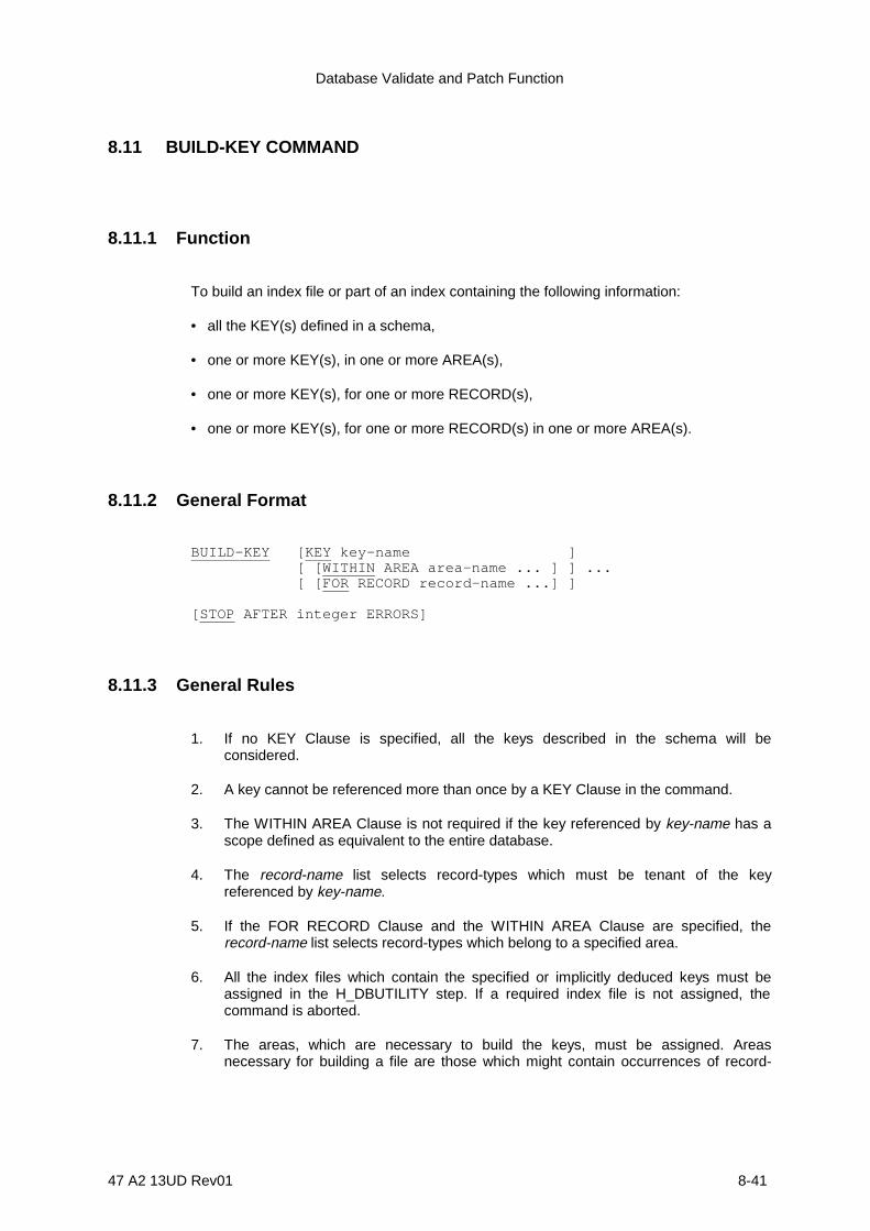
Database Validate and Patch Function
47 A2 13UD Rev01 8-41
8.11 BUILD-KEY COMMAND
8.11.1 Function
To build an index file or part of an index containing the following information:
• all the KEY(s) defined in a schema,
• one or more KEY(s), in one or more AREA(s),
• one or more KEY(s), for one or more RECORD(s),
• one or more KEY(s), for one or more RECORD(s) in one or more AREA(s).
8.11.2 General Format
BUILD-KEY [KEY key-name ] [ [WITHIN AREA area-name ... ] ] ... [ [FOR RECORD record-name ...] ]
[STOP AFTER integer ERRORS]
8.11.3 General Rules
1. If no KEY Clause is specified, all the keys described in the schema will beconsidered.
2. A key cannot be referenced more than once by a KEY Clause in the command.
3. The WITHIN AREA Clause is not required if the key referenced by key-name has ascope defined as equivalent to the entire database.
4. The record-name list selects record-types which must be tenant of the keyreferenced by key-name.
5. If the FOR RECORD Clause and the WITHIN AREA Clause are specified, therecord-name list selects record-types which belong to a specified area.
6. All the index files which contain the specified or implicitly deduced keys must beassigned in the H_DBUTILITY step. If a required index file is not assigned, thecommand is aborted.
7. The areas, which are necessary to build the keys, must be assigned. Areasnecessary for building a file are those which might contain occurrences of record-

IDS/II Administrator's Guide
8-42 47 A2 13UD Rev01
types which are tenant of the specified key. If such areas are not assigned, thecommand is aborted.
Database Validate and Patch Function
47 A2 13UD Rev01 8-43
8. The STOP ... ERRORS Clause stops processing after a specified number of errors.
9. If the STOP ... ERRORS Clause is not specified, the processing continuesregardless of the number of errors detected.
8.11.4 Execution
1. The BUILD-KEY command automatically executes the DELETE-KEY function withidentical parameters, to purge the index file before rebuilding the keys.
2. Storage areas are implicitly readied in SHARED RETRIEVAL mode. Index files areimplicitly readied in EXCLUSIVE UPDATE mode.
3. A warning message is sent when a command is launched to build a duplicate key fora key which is defined as DUPLICATES NOT ALLOWED. Processing is stoppedonly if the maximum number of errors is reached. If an error of SEV 3 results (forexample, due to an exhausted index), the building of the key is interrupted and theindex is not returned to its initial state. You should use the COMMIT and ROLLBACKcommands so that you can recover a coherent index.
4. During the execution of the BUILD-KEY command, the specified areas are examinedin the order of increasing area codes (DDL order). Only the pages containingoccurrences of record-types which are tenant of the specified keys are read.Therefore, areas are read once, with internal optimization by range. Consequently,the order of KEY Clauses has no influence on the order in which keys are built. Keysare built following the order of the occurrences of record-types.
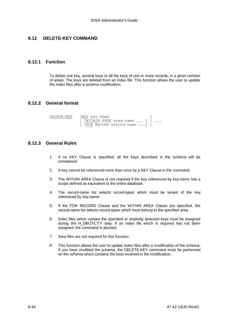
IDS/II Administrator's Guide
8-44 47 A2 13UD Rev01
8.12 DELETE-KEY COMMAND
8.12.1 Function
To delete one key, several keys or all the keys of one or more records, in a given numberof areas. The keys are deleted from an index file. This function allows the user to updatethe index files after a schema modification.
8.12.2 General format
DELETE-KEY [KEY key-name ] [ [WITHIN AREA area-name ... ] ] ... [ [FOR RECORD record-name ...] ]
8.12.3 General Rules
1. If no KEY Clause is specified, all the keys described in the schema will beconsidered.
2. A key cannot be referenced more than once by a KEY Clause in the command.
3. The WITHIN AREA Clause is not required if the key referenced by key-name has ascope defined as equivalent to the entire database.
4. The record-name list selects record-types which must be tenant of the keyreferenced by key-name.
5. If the FOR RECORD Clause and the WITHIN AREA Clause are specified, therecord-name list selects record-types which must belong to the specified area.
6. Index files which contain the specified or implicitly deduced keys must be assignedduring the H_DBUTILITY step. If an index file which is required has not beenassigned, the command is aborted.
7. Area files are not required for this function.
8. This function allows the user to update index files after a modification of the schema.If you have modified the schema, the DELETE-KEY command must be performedon the schema which contains the keys involved in the modification.
Database Validate and Patch Function
47 A2 13UD Rev01 8-45
8.12.4 Execution
1. Index files are implicitly readied in EXCLUSIVE UPDATE mode.
2. During the execution of the DELETE-KEY command, keys are deleted in thefollowing order:
- by increasing order of key codes (DDL order), if no key is specified in thecommand,
- by the order specified in the KEY Clauses.

IDS/II Administrator's Guide
8-46 47 A2 13UD Rev01
8.13 CONDITIONS IN A CONCURRENT ACCESS ENVIRONMENT
DBUTILITY performs one of two functions.
1) It performs RETRIEVAL or UPDATE operations,
2) or, it authorizes or forbids concurrent updates.
Table 8-1 shows the ASSIGN/DEFINE parameters for each type of command. Blocks withdiagonal dashes in the table indicate combinations which are not allowed. Because of thevariety of sharing modes and area protection levels, four modes of use are provided,which should be used in independent sessions. These modes are listed below anddescribed below:
1) Global validation mode (VALIDATE POINTERS Command)
2) Local validation mode (VALIDATE PAGE Command)
3) Local modification and validation mode (PATCH RECORD or PAGE Command,RECONNECT RECORD Command, VALIDATE PAGE Command)
4) Key administration mode (BUILD-KEY, DELETE-KEY)
In Global Validation mode, the areas are readied in SHARED RETRIEVAL mode, allowingconcurrent readers who are working in the same sharing mode. There is no page locking.
In Local Validation mode, the areas are readied in MONITORED RETRIEVAL mode,allowing concurrent readers and writers who are working in MONITORED mode. WhenREADLOCK = EXCL or NORMAL, there is a possibility of wait or deadlock, since pagesare locked in this mode. In the case of a deadlock, the step is restarted from the lastcommitment-point. In this mode, the COMMIT function must be used from time to time tounlock the pages accessed by previous VALIDATE PAGE commands.
When READLOCK = STAT, there is a possibility of apparent inconsistencies, specificallywith a VALIDATE PAGE GLOBALLY command. Therefore READLOCK = STAT is notrecommended for a command which is checking for real inconsistencies.
Using JCL, you can override the MONITORED mode with either the SHARED orEXCLUSIVE mode. This is advisable if VALIDATE PAGE commands involve large rangesof pages. There is no page locking in this mode.
In Local Modification and Validation mode, areas are readied in MONITORED UPDATEmode, allowing concurrent readers and writers who are working in MONITORED mode.The BEFORE Journal is required. In this mode, pages are locked and there is, therefore,a possibility of wait or deadlock. In the case of deadlock, the step is restarted from the lastcommitment-point. The COMMIT command must be used to make the modificationsdefinitive. The same command must be used to unlock the pages which were accessedby a previous PATCH or VALIDATE PAGE command.
In Key Administration mode, index files are readied in EXCLUSIVE UPDATE mode. In thiscase, the BEFORE Journal is not mandatory if the ROLLBACK command has not to beused. In this mode, there is no page locking.
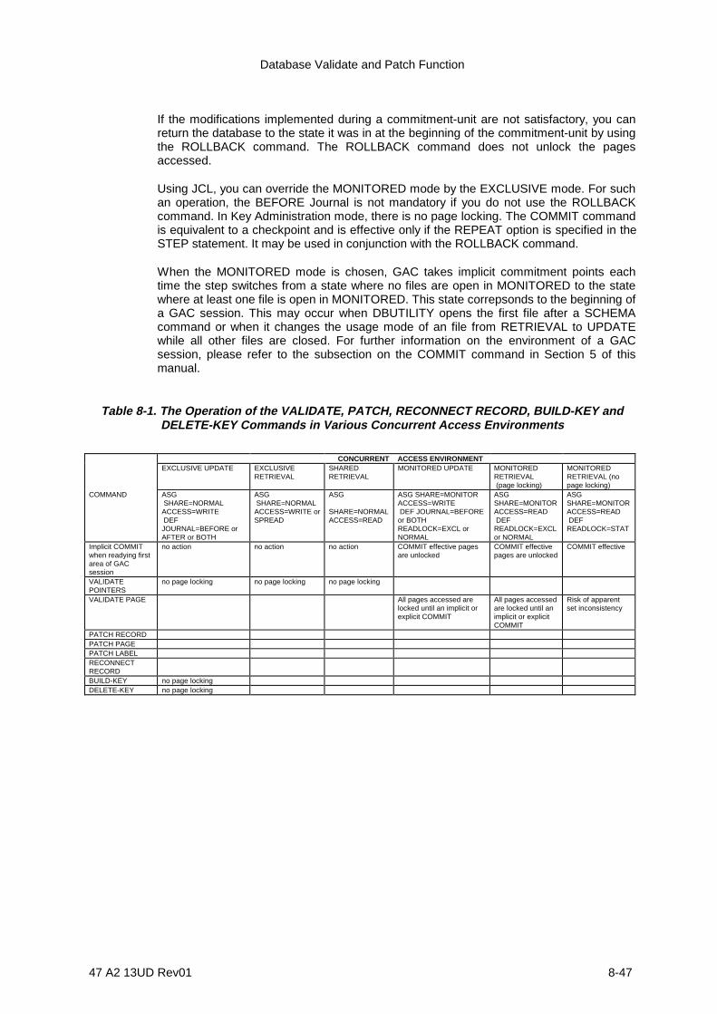
Database Validate and Patch Function
47 A2 13UD Rev01 8-47
If the modifications implemented during a commitment-unit are not satisfactory, you canreturn the database to the state it was in at the beginning of the commitment-unit by usingthe ROLLBACK command. The ROLLBACK command does not unlock the pagesaccessed.
Using JCL, you can override the MONITORED mode by the EXCLUSIVE mode. For suchan operation, the BEFORE Journal is not mandatory if you do not use the ROLLBACKcommand. In Key Administration mode, there is no page locking. The COMMIT commandis equivalent to a checkpoint and is effective only if the REPEAT option is specified in theSTEP statement. It may be used in conjunction with the ROLLBACK command.
When the MONITORED mode is chosen, GAC takes implicit commitment points eachtime the step switches from a state where no files are open in MONITORED to the statewhere at least one file is open in MONITORED. This state correpsonds to the beginning ofa GAC session. This may occur when DBUTILITY opens the first file after a SCHEMAcommand or when it changes the usage mode of an file from RETRIEVAL to UPDATEwhile all other files are closed. For further information on the environment of a GACsession, please refer to the subsection on the COMMIT command in Section 5 of thismanual.
Table 8-1. The Operation of the VALIDATE, PATCH, RECONNECT RECORD, BUILD-KEY andDELETE-KEY Commands in Various Concurrent Access Environments
CONCURRENT ACCESS ENVIRONMENTEXCLUSIVE UPDATE EXCLUSIVE
RETRIEVALSHAREDRETRIEVAL
MONITORED UPDATE MONITOREDRETRIEVAL (page locking)
MONITOREDRETRIEVAL (nopage locking)
COMMAND ASG SHARE=NORMALACCESS=WRITE DEFJOURNAL=BEFORE orAFTER or BOTH
ASG SHARE=NORMALACCESS=WRITE orSPREAD
ASG
SHARE=NORMALACCESS=READ
ASG SHARE=MONITORACCESS=WRITE DEF JOURNAL=BEFOREor BOTHREADLOCK=EXCL orNORMAL
ASGSHARE=MONITORACCESS=READ DEFREADLOCK=EXCLor NORMAL
ASGSHARE=MONITORACCESS=READ DEFREADLOCK=STAT
Implicit COMMITwhen readying firstarea of GACsession
no action no action no action COMMIT effective pagesare unlocked
COMMIT effectivepages are unlocked
COMMIT effective
VALIDATEPOINTERS
no page locking no page locking no page locking
VALIDATE PAGE All pages accessed arelocked until an implicit orexplicit COMMIT
All pages accessedare locked until animplicit or explicitCOMMIT
Risk of apparentset inconsistency
PATCH RECORDPATCH PAGEPATCH LABELRECONNECTRECORDBUILD-KEY no page lockingDELETE-KEY no page locking
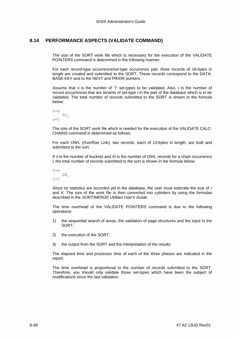
IDS/II Administrator's Guide
8-48 47 A2 13UD Rev01
8.14 PERFORMANCE ASPECTS (VALIDATE COMMAND)
The size of the SORT work file which is necessary for the execution of the VALIDATEPOINTERS command is determined in the following manner:
For each record-type occurrence/set-type occurrence pair, three records of 18-bytes inlength are created and submitted to the SORT. These records correspond to the DATA-BASE-KEY and to the NEXT and PRIOR pointers.
Assume that s is the number of "i" set-types to be validated. Also, r is the number ofrecord occurrences that are tenants of set-type i in the part of the database which is to bevalidated. The total number of records submitted to the SORT is shown in the formulabelow:
i=s 3r ii=1
The size of the SORT work file which is needed for the execution of the VALIDATE CALC-CHAINS command is determined as follows:
For each OWL (Overflow Link), two records, each of 13-bytes in length, are built andsubmitted to the sort.
If n is the number of buckets and Ki is the number of OWL records for a chain occurrencei, the total number of records submitted to the sort is shown in the formula below:
i=n 2K ii=1
Since no statistics are recorded yet in the database, the user must estimate the size of rand K. The size of the work file is then converted into cylinders by using the formulasdescribed in the SORT/MERGE Utilities User's Guide.
The time overhead of the VALIDATE POINTERS command is due to the followingoperations:
1) the sequential search of areas, the validation of page structures and the input to theSORT,
2) the execution of the SORT,
3) the output from the SORT and the interpretation of the results.
The elapsed time and processor time of each of the three phases are indicated in thereport.
The time overhead is proportional to the number of records submitted to the SORT.Therefore, you should only validate those set-types which have been the subject ofmodifications since the last validation.

Database Validate and Patch Function
47 A2 13UD Rev01 8-49
8.15 DBVALID EXAMPLES
Example 1
Consider the database described by a schema named INVENTORY. The portion of thedatabase which is to be validated consists of areas PART-INVENTORY andCUSTOMER-BASE, which are illustrated below:
PARTC U S T O M E R
O R D E R S
ORDER- ITEM
PART- INVENTORY CUSTOMER-BASE
ITEMS-OF-ORDER
ORDERS-OF-CUSTOME
This database contains the following records:
1) 5000 CUSTOMER records and 10,000 ORDERS records participating in set-typeORDERS-OF-CUSTOMER
2) 10,000 ORDERS records and 20,000 ORDER-ITEM records participating in set-typeITEMS-OF-ORDER
3) 5000 PART records and 20,000 ORDER-ITEM records participating in set-typeITEMS-WHERE-PART
The number of records submitted to the SORT will be:
3 (5000+10000) + 3 (10000+20000) + 3 (5000+20000) = 210,000
The number of cylinders required for sorting 210,000 records of 20-bytes in length isapproximately 25. This is greater than the default value of 10. Further information on thissubject is provided in the SORT/MERGE Utilities User's Guide.
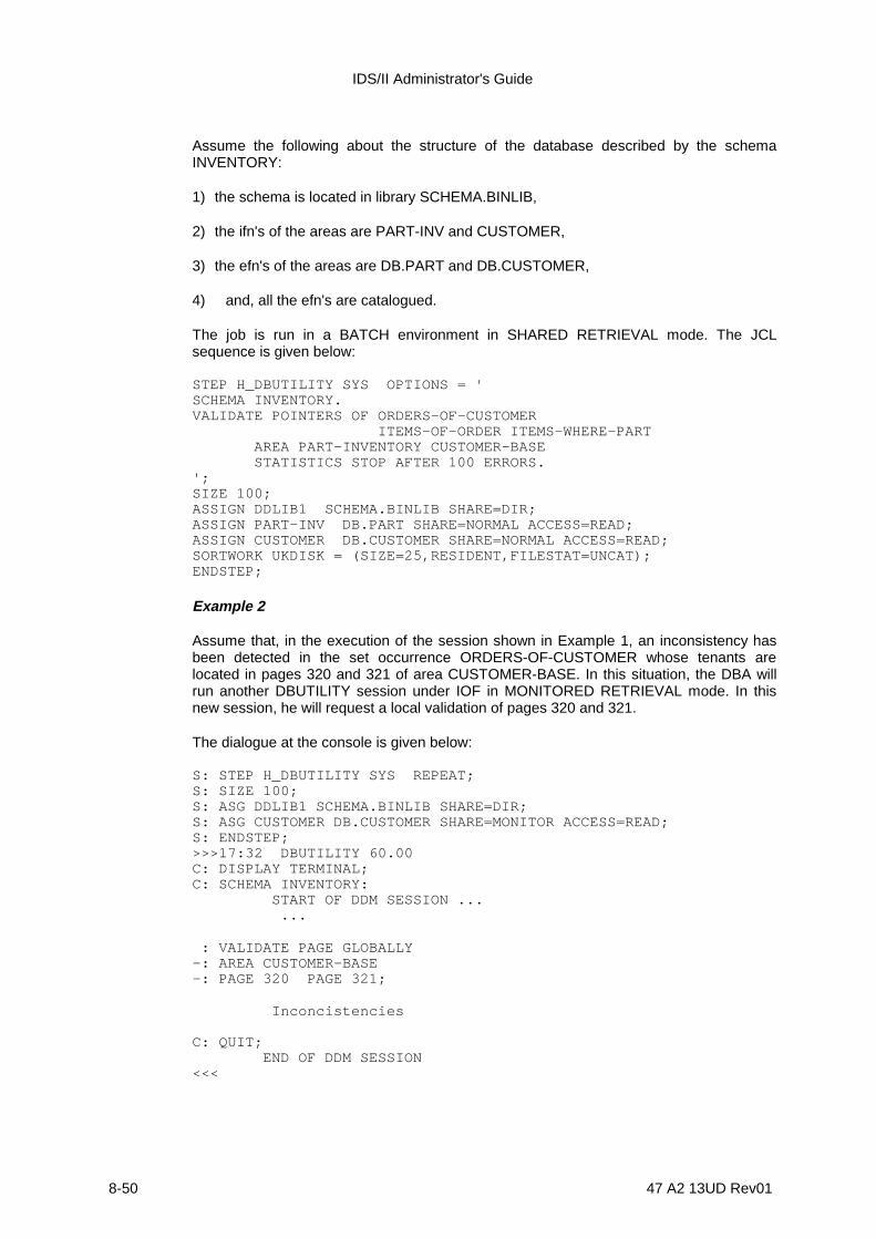
IDS/II Administrator's Guide
8-50 47 A2 13UD Rev01
Assume the following about the structure of the database described by the schemaINVENTORY:
1) the schema is located in library SCHEMA.BINLIB,
2) the ifn's of the areas are PART-INV and CUSTOMER,
3) the efn's of the areas are DB.PART and DB.CUSTOMER,
4) and, all the efn's are catalogued.
The job is run in a BATCH environment in SHARED RETRIEVAL mode. The JCLsequence is given below:
STEP H_DBUTILITY SYS OPTIONS = 'SCHEMA INVENTORY.VALIDATE POINTERS OF ORDERS-OF-CUSTOMER ITEMS-OF-ORDER ITEMS-WHERE-PART AREA PART-INVENTORY CUSTOMER-BASE STATISTICS STOP AFTER 100 ERRORS.';SIZE 100;ASSIGN DDLIB1 SCHEMA.BINLIB SHARE=DIR;ASSIGN PART-INV DB.PART SHARE=NORMAL ACCESS=READ;ASSIGN CUSTOMER DB.CUSTOMER SHARE=NORMAL ACCESS=READ;SORTWORK UKDISK = (SIZE=25,RESIDENT,FILESTAT=UNCAT);ENDSTEP;
Example 2
Assume that, in the execution of the session shown in Example 1, an inconsistency hasbeen detected in the set occurrence ORDERS-OF-CUSTOMER whose tenants arelocated in pages 320 and 321 of area CUSTOMER-BASE. In this situation, the DBA willrun another DBUTILITY session under IOF in MONITORED RETRIEVAL mode. In thisnew session, he will request a local validation of pages 320 and 321.
The dialogue at the console is given below:
S: STEP H_DBUTILITY SYS REPEAT;S: SIZE 100;S: ASG DDLIB1 SCHEMA.BINLIB SHARE=DIR;S: ASG CUSTOMER DB.CUSTOMER SHARE=MONITOR ACCESS=READ;S: ENDSTEP;>>>17:32 DBUTILITY 60.00C: DISPLAY TERMINAL;C: SCHEMA INVENTORY: START OF DDM SESSION ... ...
: VALIDATE PAGE GLOBALLY-: AREA CUSTOMER-BASE-: PAGE 320 PAGE 321;
Inconcistencies
C: QUIT; END OF DDM SESSION<<<

Database Validate and Patch Function
47 A2 13UD Rev01 8-51
Example 3
After the execution of the sessions illustrated in Examples 1 and 2, the DBA concludesthat the inconcistency is the following:
C U S T O M E R
O R D E R S O R D E R S
P 1,320,5 P
P
N
N
OO
N
1,321,9 1,321,10
The owner record CUSTOMER indicates that the set occurrence ORDERS-OF-CUSTOMER is empty, but at the same time two ORDERS records are referencing thatset in their OWNER pointers. The DBA runs a DBUTILITY session under IOF inMONITORED UPDATE mode to modify the NEXT and PRIOR pointers of the ownerrecord.
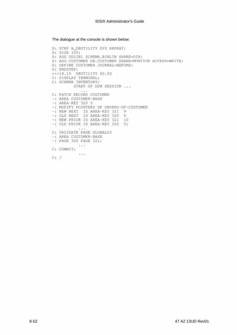
IDS/II Administrator's Guide
8-52 47 A2 13UD Rev01
The dialogue at the console is shown below:
S: STEP H_DBUTILITY SYS REPEAT;S: SIZE 100;S: ASG DDLIB1 SCHEMA.BINLIB SHARE=DIR;S: ASG CUSTOMER DB.CUSTOMER SHARE=MONITOR ACCESS=WRITE;S: DEFINE CUSTOMER JOURNAL=BEFORE;S: ENDSTEP;>>>18.15 DBUTILITY 60.00C: DISPLAY TERMINAL;C: SCHEMA INVENTORY; START OF DDM SESSION ... ...C: PATCH RECORD CUSTOMER-: AREA CUSTOMER-BASE-: AREA-KEY 320 5-: MODIFY POINTERS OF ORDERS-OF-CUSTOMER-: NEW NEXT IS AREA-KEY 321 9-: OLD NEXT IS AREA-KEY 320 5-: NEW PRIOR IS AREA-KEY 321 10-: OLD PRIOR IS AREA-KEY 320 5; ...C: VALIDATE PAGE GLOBALLY-: AREA CUSTOMER-BASE-: PAGE 320 PAGE 321; ...C: COMMIT; ...C: /

Database Validate and Patch Function
47 A2 13UD Rev01 8-53
47 A2 13UD Rev01 9-1
9. Interactive Data Manipulation Functions
9.1 DBDIALOG FUNCTIONS
DBDIALOG, the interactive Data Manipulation Language (DML), is described below by alist of its functions. DBDIALOG performs the following operations:
1) It creates and initializes user working storage variables. These variables are workingstorage areas and may be used to save or to restore the contents of fields orrecords. They can also be referenced in specific data manipulation commands.
2) It performs the interactive execution of all Data Manipulation Language statementsexcept two: DBDIALOG cannot execute the Database Condition (IF) statement orthe USE COBOL statement.
3) It displays the following elements:
- the contents of records which are read from the database,- the contents of DB-PARAMETERS as they would appear in a COBOL program,- the contents of DB-REGISTERS and of DETAILED-STATUS,- and the contents of all created working storage areas.
4) It display the contents of currency indicators, in order to familiarize the user with theirupdating mechanisms.
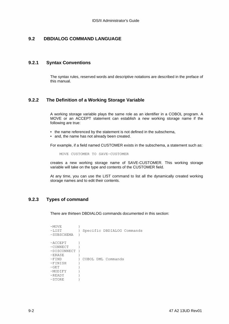
IDS/II Administrator's Guide
9-2 47 A2 13UD Rev01
9.2 DBDIALOG COMMAND LANGUAGE
9.2.1 Syntax Conventions
The syntax rules, reserved words and descriptive notations are described in the preface ofthis manual.
9.2.2 The Definition of a Working Storage Variable
A working storage variable plays the same role as an identifier in a COBOL program. AMOVE or an ACCEPT statement can establish a new working storage name if thefollowing are true:
• the name referenced by the statement is not defined in the subschema,• and, the name has not already been created.
For example, if a field named CUSTOMER exists in the subschema, a statement such as:
MOVE CUSTOMER TO SAVE-CUSTOMER
creates a new working storage name of SAVE-CUSTOMER. This working storagevariable will take on the type and contents of the CUSTOMER field.
At any time, you can use the LIST command to list all the dynamically created workingstorage names and to edit their contents.
9.2.3 Types of command
There are thirteen DBDIALOG commands documented in this section:
-MOVE }-LIST } Specific DBDIALOG Commands-SUBSCHEMA }
-ACCEPT }-CONNECT }-DISCONNECT }-ERASE }-FIND } COBOL DML Commands-FINISH }-GET }-MODIFY }-READY }-STORE }
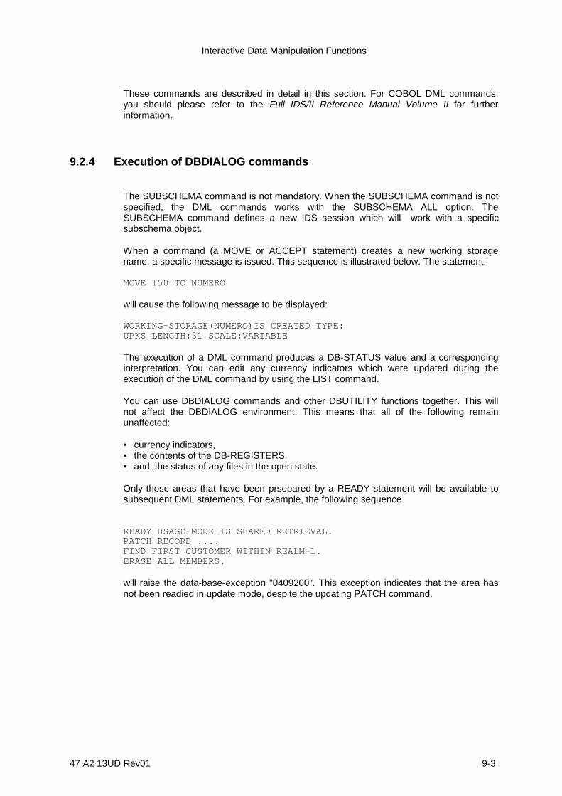
Interactive Data Manipulation Functions
47 A2 13UD Rev01 9-3
These commands are described in detail in this section. For COBOL DML commands,you should please refer to the Full IDS/II Reference Manual Volume II for furtherinformation.
9.2.4 Execution of DBDIALOG commands
The SUBSCHEMA command is not mandatory. When the SUBSCHEMA command is notspecified, the DML commands works with the SUBSCHEMA ALL option. TheSUBSCHEMA command defines a new IDS session which will work with a specificsubschema object.
When a command (a MOVE or ACCEPT statement) creates a new working storagename, a specific message is issued. This sequence is illustrated below. The statement:
MOVE 150 TO NUMERO
will cause the following message to be displayed:
WORKING-STORAGE(NUMERO)IS CREATED TYPE:UPKS LENGTH:31 SCALE:VARIABLE
The execution of a DML command produces a DB-STATUS value and a correspondinginterpretation. You can edit any currency indicators which were updated during theexecution of the DML command by using the LIST command.
You can use DBDIALOG commands and other DBUTILITY functions together. This willnot affect the DBDIALOG environment. This means that all of the following remainunaffected:
• currency indicators,• the contents of the DB-REGISTERS,• and, the status of any files in the open state.
Only those areas that have been prsepared by a READY statement will be available tosubsequent DML statements. For example, the following sequence
READY USAGE-MODE IS SHARED RETRIEVAL.PATCH RECORD ....FIND FIRST CUSTOMER WITHIN REALM-1.ERASE ALL MEMBERS.
will raise the data-base-exception "0409200". This exception indicates that the area hasnot been readied in update mode, despite the updating PATCH command.

IDS/II Administrator's Guide
9-4 47 A2 13UD Rev01
9.3 SUBSCHEMA COMMAND
9.3.1 Function
To specify the object subschema to which subsequent DBDIALOG commands apply.
9.3.2 General Format
SUBSCHEMA NAME IS subschema-name .
9.3.3 Rules
1. The specified subschema must be a valid subschema of the current loaded schema.A SCHEMA command must be previously specified.
2. The subschema is searched for in the library from which the current schema hasbeen loaded.
3. A subschema command unloads the current loaded subschema, if any, anddeallocates all work variables which were created and initialized by any previousDBDIALOG commands.
4. If no subschema name is specified, the default subschema ALL is assumed.
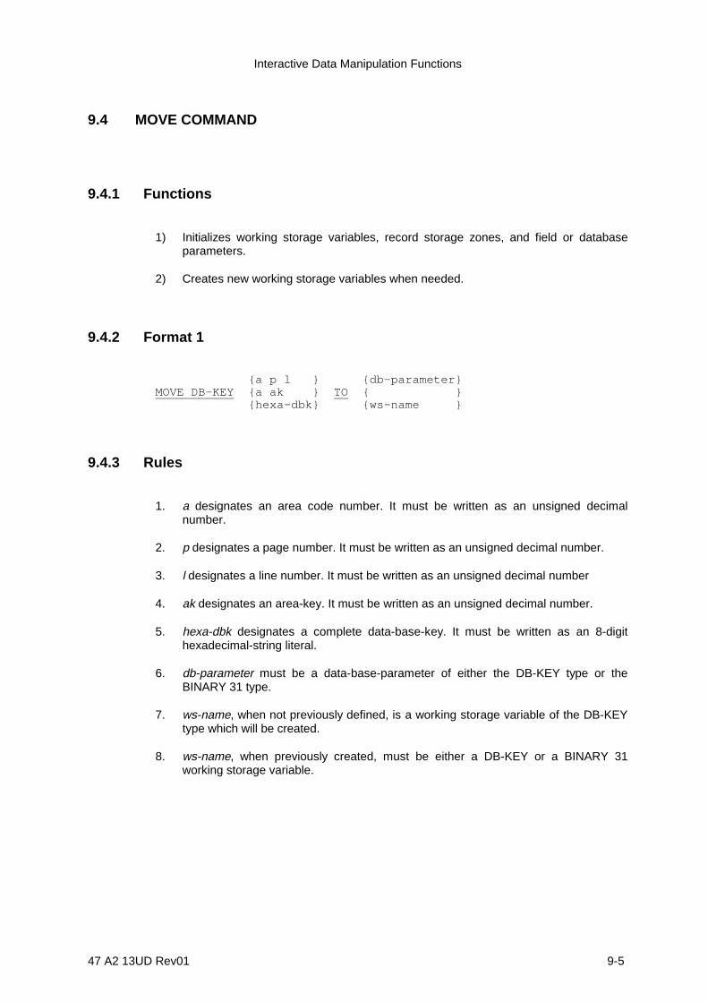
Interactive Data Manipulation Functions
47 A2 13UD Rev01 9-5
9.4 MOVE COMMAND
9.4.1 Functions
1) Initializes working storage variables, record storage zones, and field or databaseparameters.
2) Creates new working storage variables when needed.
9.4.2 Format 1
{a p l } {db-parameter}MOVE DB-KEY {a ak } TO { } {hexa-dbk} {ws-name }
9.4.3 Rules
1. a designates an area code number. It must be written as an unsigned decimalnumber.
2. p designates a page number. It must be written as an unsigned decimal number.
3. l designates a line number. It must be written as an unsigned decimal number
4. ak designates an area-key. It must be written as an unsigned decimal number.
5. hexa-dbk designates a complete data-base-key. It must be written as an 8-digithexadecimal-string literal.
6. db-parameter must be a data-base-parameter of either the DB-KEY type or theBINARY 31 type.
7. ws-name, when not previously defined, is a working storage variable of the DB-KEYtype which will be created.
8. ws-name, when previously created, must be either a DB-KEY or a BINARY 31working storage variable.

IDS/II Administrator's Guide
9-6 47 A2 13UD Rev01
9.4.4 Format 2
{integer }MOVE {decimal } TO ws-name {char-literal} {hexa-literal}
9.4.5 Rules
1. integer represents a signed or unsigned integer.
2. decimal represents a signed or unsigned decimal number.
3. char-literal represents a character-string literal.
4. hexa-literal represents a hexadecimal-string literal.
5. ws-name, when not previously defined, is a working storage variable which will becreated.
If the sending item is an integer or a decimal number, the working-storage itemcreated will be of the SIGNED UNPACKED 31 type with potentially variable scale.
If the sending item is a character string literal or a hexadecimal string literal, theworking-storage item created will be of CHARACTER type with potentially variablelength.
6. ws-name, when previously created, is a working storage variable. In this case, thesending item must conform to the rules for the comparison of data-base-identifiersand literals, as specified in Figure 2-2 of the Full IDS/II Reference Manual Volume I.
9.4.6 Format 3
{record-name-1} {record-name-2}MOVE { } TO { } {ws-name-1 } {ws-name-2 }

Interactive Data Manipulation Functions
47 A2 13UD Rev01 9-7
9.4.7 Rules
1. ws-name-2, when not previously defined, is a working storage variable which will becreated. It is created with the attributes of the sending item: type, length, scale andstructure. If the sending item is a record or a working storage variable created as acopied version of a record, the new working storage variable takes on the length andstructure of the corresponding record and keeps the record attribute. When thereceiving item is a working storage variable created as a copied version of a record,the execution of the MOVE command will not modify its description.
2. If the sending item contains the record attribute, the receiving item must also be ofrecord attribute. It must also have exactly the same length as the sending item. TheMOVE command is executed as a character-string move.
3. In order for the MOVE command to execute successfully, the sending and receivingitems should conform to the correspondance rules between sending and receivingitems.
9.4.8 Format 4
{db-parameter }MOVE field-type-literal TO {field-identifier-2 {OF} } { {IN} ws-name }
9.4.9 Rules
1. db-parameter must be a data-base-parameter available to the subschema named inthe previous SUBSCHEMA command.
2. field-identifier-1 must include the qualification IN (OF) record-name, if the same field-name appears in several record-types of the subschema.
3. field-identifier-1 and field-identifier-2 represent elementary items.
4. field-identifier-1 and field-identifier-2 must be subscripted when needed. The star (*)convention may be used in place of a subscript value to obtain all occurrences of asubscript.
5. If the record which contains field-identifier-1 has not yet been referenced by a GETor MOVE command, a working storage receiving zone is created with the name,length and structure of the corresponding record as defined in the subschema.
6. ws-name is a working storage variable which must be created beforehand as acopied version of the record which contains field-identifier-2. It must be created bymeans of a MOVE record-name to ws-name command.
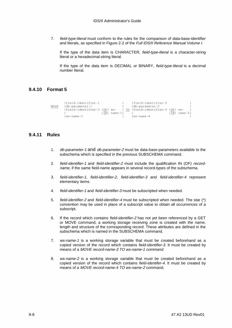
IDS/II Administrator's Guide
9-8 47 A2 13UD Rev01
7. field-type-literal must conform to the rules for the comparison of data-base-identifierand literals, as specified in Figure 2-2 of the Full IDS/II Reference Manual Volume I.
If the type of the data item is CHARACTER, field-type-literal is a character-stringliteral or a hexadecimal-string literal.
If the type of the data item is DECIMAL or BINARY, field-type-literal is a decimalnumber literal.
9.4.10 Format 5
{field-identifier-1 } {field-identifier-2 }MOVE {db-parameter-1 } {db-parameter-2 } {field-identifier-3 {OF} ws- } TO {field-identifier-4 {OF } ws- } { {IN} name-1} { {IN } name-2} {ws-name-3 } {ws-name-4 }
9.4.11 Rules
1. db-parameter-1 and db-parameter-2 must be data-base-parameters available to thesubschema which is specified in the previous SUBSCHEMA command.
2. field-identifier-1 and field-identifier-2 must include the qualification IN (OF) record-name, if the same field-name appears in several record-types of the subschema.
3. field-identifier-1, field-identifier-2, field-identifier-3 and field-identifier-4 representelementary items.
4. field-identifier-1 and field-identifier-3 must be subscripted when needed.
5. field-identifier-2 and field-identifier-4 must be subscripted when needed. The star (*)convention may be used in place of a subscript value to obtain all occurrences of asubscript.
6. If the record which contains field-identifier-2 has not yet been referenced by a GETor MOVE command, a working storage receiving zone is created with the name,length and structure of the corresponding record. These attributes are defined in thesubschema which is named in the SUBSCHEMA command.
7. ws-name-1 is a working storage variable that must be created beforehand as acopied version of the record which contains field-identifier-3. It must be created bymeans of a MOVE record-name-3 TO ws-name-1 command.
8. ws-name-2 is a working storage variable that must be created beforehand as acopied version of the record which contains field-identifer-4. It must be created bymeans of a MOVE record-name-4 TO ws-name-2 command.

Interactive Data Manipulation Functions
47 A2 13UD Rev01 9-9
9. ws-name-3 and ws-name-4 designate working storage variables. When notpreviously created, ws-name-4 will be created with the type, length and, if applicable,the scale of the sending item specified in the MOVE command.
10. If ws-name-4 has been created using a MOVE command of Format 2, or by anACCEPT statement, one of the following attributes will match those of the sendingitem:
- its length (if it is of CHARACTER type),
- or its scale (if it is of DECIMAL type).
11. In order for the MOVE command execute successfully, the sending and receivingitems should conform to the correspondance rules as specified below:
Receiving itemTYPE
Sendingitem TYPE
RECORD DB-KEY DECIMALm, +p
BINARY 15 BINARY 31 CHARACTER n
RECORD YES if samelength
DB-KEY YES YESDECIMAL m, + p YES (1)(2) YES (1) IFp = 0 YES (1)IFp = 0 YES (1) if
UNSIGNEDUNPACKEDm,o
BINARY 15 YES (1)(2) YES YESBINARY 31 YES YES (1)(2) YES (1) YESCHARACTER n YES (1)
Legend :(1) possible truncation and/or loss of precision(2) possible loss of minus sign
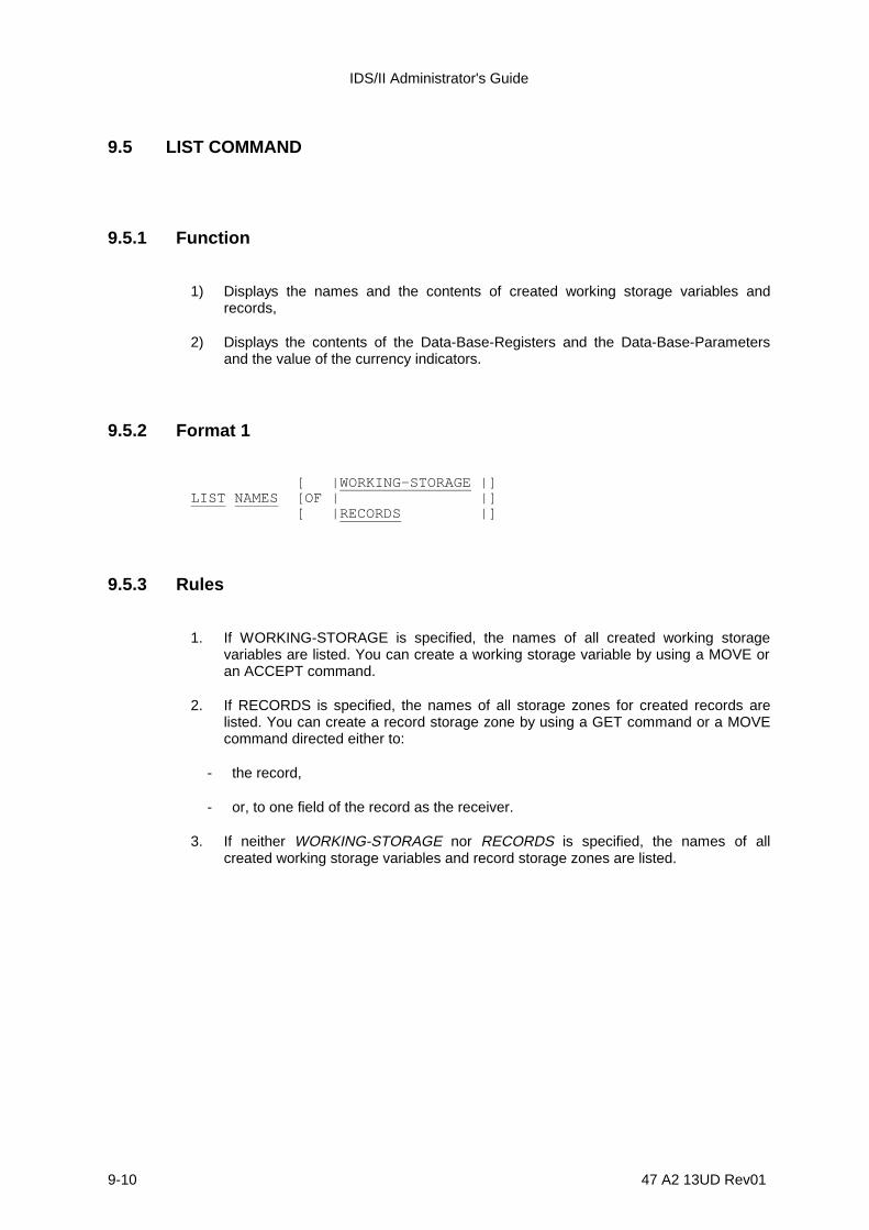
IDS/II Administrator's Guide
9-10 47 A2 13UD Rev01
9.5 LIST COMMAND
9.5.1 Function
1) Displays the names and the contents of created working storage variables andrecords,
2) Displays the contents of the Data-Base-Registers and the Data-Base-Parametersand the value of the currency indicators.
9.5.2 Format 1
[ |WORKING-STORAGE |]LIST NAMES [OF | |] [ |RECORDS |]
9.5.3 Rules
1. If WORKING-STORAGE is specified, the names of all created working storagevariables are listed. You can create a working storage variable by using a MOVE oran ACCEPT command.
2. If RECORDS is specified, the names of all storage zones for created records arelisted. You can create a record storage zone by using a GET command or a MOVEcommand directed either to:
- the record,
- or, to one field of the record as the receiver.
3. If neither WORKING-STORAGE nor RECORDS is specified, the names of allcreated working storage variables and record storage zones are listed.
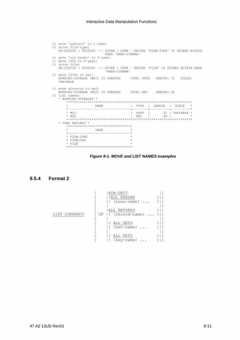
Interactive Data Manipulation Functions
47 A2 13UD Rev01 9-11
C: move "western" to t-name;C: store film-type; DB-STATUS : 0000000 --> STORE : DONE - RECORD "FILM-TYPE" IS STORED WITHIN AREA "AREA-CINEMA"C: move "rio bravo" to f-name;C: move 1952 to f-year;C: store film; DB-STATUS : 0000000 --> STORE : DONE - RECORD "FILM" IS STORED WITHIN AREA "AREA-CINEMA"C: move 12345 to ws1; WORKING-STORAGE (WS1) IS CREATED TYPE: UPKS LENGTH: 31 SCALE: VARIABLE
C: move director to ws2; WORKING-STORAGE (WS2) IS CREATED TYPE: REC LENGTH: 60C: list names; * WORKING-STORAGES * ***************************************************************** * NAME : TYPE : LENGTH : SCALE * *--------------------------------+--------+----------+----------* * WS1 : UPKS : 31 : VARIABLE * * WS2 : REC : 60 : * ***************************************************************** * USED RECORDS * ********************************** * NAME * *--------------------------------* * FILM-TYPE * * DIRECTOR * * FILM * **********************************
Figure 9-1. MOVE and LIST NAMES examples
9.5.4 Format 2
[ |RUN-UNIT |] [ |{ALL REALMS }|] [ |{ {area-name} ... }|] [ | |] [ |ALL RECORDS }|]LIST CURRENCY [ OF |{ {record-name} ... }|] [ | |] [ |{ ALL SETS }|] [ |{ {set-name} ... }|] [ | |] [ |{ ALL KEYS }|] [ |{ {key-name} ... }|]
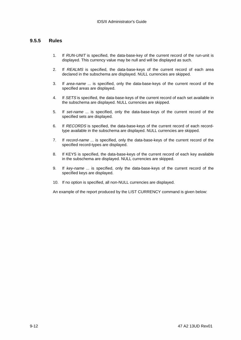
IDS/II Administrator's Guide
9-12 47 A2 13UD Rev01
9.5.5 Rules
1. If RUN-UNIT is specified, the data-base-key of the current record of the run-unit isdisplayed. This currency value may be null and will be displayed as such.
2. If REALMS is specified, the data-base-keys of the current record of each areadeclared in the subschema are displayed. NULL currencies are skipped.
3. If area-name ... is specified, only the data-base-keys of the current record of thespecified areas are displayed.
4. If SETS is specified, the data-base-keys of the current record of each set available inthe subschema are displayed. NULL currencies are skipped.
5. If set-name ... is specified, only the data-base-keys of the current record of thespecified sets are displayed.
6. If RECORDS is specified, the data-base-keys of the current record of each record-type available in the subschema are displayed. NULL currencies are skipped.
7. If record-name ... is specified, only the data-base-keys of the current record of thespecified record-types are displayed.
8. If KEYS is specified, the data-base-keys of the current record of each key availablein the subschema are displayed. NULL currencies are skipped.
9. If key-name ... is specified, only the data-base-keys of the current record of thespecified keys are displayed.
10. If no option is specified, all non-NULL currencies are displayed.
An example of the report produced by the LIST CURRENCY command is given below:

Interactive Data Manipulation Functions
47 A2 13UD Rev01 9-13
C: 213 214 FIND FROM K01. DB-STATUS : 0000000 --> FIND : DONE - RECORD "R02" IS FOUND WITHIN AREA "A00"
C: 214 215 LIST CURRENCY . * CURRENT-OF-RUN-UNIT * RECORD:R02 DBK:00000086 A:0 P:4 L:14 AN:A00 * CURRENT-OF-REALM * AREA :A00 DBK:00000086 A:0 P:4 L:14 RN:R02 * CURRENT-OF-SET * SET :S01 DBK:00000086 A:0 P:4 L:14 AN:A00 RN:R02 SET :S02 DBK:00000086 A:0 P:4 L:14 AN:A00 RN:R02 SET :S06 DBK:00000086 A:0 P:4 L:14 AN:A00 RN:R02 * CURRENT-OF-RECORD * RECORD:R02 DBK:00000086 A:0 P:4 L:14 AN:A00 * CURRENT-OF-KEY * KEY: K01 DBK:00000086 A:0 P:4 L:14 AN:A00 RN:R02 KEY: K02 DBK:00000086 A:0 P:4 L:14 AN:A00 RN:R02 KEY: K09 DBK:00000086 A:0 P:4 L:14 AN:A00 RN:R02
Figure 9-2. An Example of the Report Produced by the LIST CURRENCY command
9.5.6 Format 3
|DB-REGISTERS | | | | {DB-PARAMETERS } | | { {db-parameter} ... } |LIST CONTENTS [OF | {RECORDS } | ] | { } | | {|{record-name-1} ... |} | | {|{field-identifier-1} .. |} | | {WORKING-STORAGE } | | { } | | {|{ws-name-1} ... |} | | {|{field-identifier-2 OF ws-name-2} ...|} |

IDS/II Administrator's Guide
9-14 47 A2 13UD Rev01
9.5.7 Rules
1. If DB-REGISTERS is specified, the contents of DB-STATUS, DB-REALM-NAME,DB-RECORD-NAME and DB-SET-NAME are displayed together with the contents ofthe DB-DETAILED-STATUS, if the latter is not empty.
2. If DB-PARAMETERS is specified, the contents of all data-base-parameters aredisplayed.
3. If db-parameter ... is specified, only the contents of the specified data-base-parameters are displayed.
4. If RECORDS is specified, the contents of all records which contain fields declared inthe Subschema DDL are displayed.
5. If field-identifier-1 ... is specified, only the contents of the specified fields aredisplayed.
6. If WORKING-STORAGE is specified, the contents of all created working storagevariables are displayed.
7. If ws-name-1 ... is specified, only the contents of the specified working storagevariables are displayed.
8. If ws-name-1 ... is the name of a working storage variable created from a record bymeans of a MOVE record-name TO ws-name command, it is displayed exactly asthe corresponding record.
9. ws-name-2 ... must be a working storage variable created from a record by means ofa MOVE record-name TO ws-name command.
10. field-identifier-2 must be a field of the record that has been used to create the ws-name-2 working storage variable.
11. field-identifier-1 must include the qualification IN (OF) record-name, if the same field-name appears in several record-types of the subschema.
12. field-identifier-1 and field-identifier-2 may be subscripted when needed. The star(*) convention may be used in place of a subscript value to obtain all occurrences ofa subscript. For example, if A is a field with two subscripts,
LIST CONTENTS OF A is equivalent to
LIST CONTENTS OF A(*,*).
13. field-identifier-1 and field-identifier-2 may be aggregates. In this case, they areequivalent to the list of all the elementary fields they contain.
14. When no option is specified, all the following are displayed: DB-REGISTERS, alldata-base-parameters, records and working-storage.
The edition format for db-parameters, records and working storage variables is thesame format used for the PRINT RECORD command. Please refer to the

Interactive Data Manipulation Functions
47 A2 13UD Rev01 9-15
subsection entitled "Database Print Functions" in Section 6 of this manual for detailson the PRINT RECORD command .
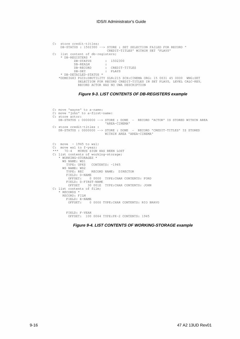
IDS/II Administrator's Guide
9-16 47 A2 13UD Rev01
C: store credit-titles; DB-STATUS : 1502300 --> STORE : SET SELECTION FAILED FOR RECORD " CREDIT-TITLES" WITHIN SET "PLAYS"C: list content of db-registers; * DB-REGISTERS * DB-STATUS : 1502300 DB-REALM : DB-RECORD : CREDIT-TITLES DB-SET : PLAYS * DB-DETAILED-STATUS * *DDM03683 PGID:DBUTILITY SLN:215 SCH:CINEMA ORG: 15 0031 45 0000 WNG:SET SELECTION FOR RECORD CREDIT-TITLES IN SET PLAYS, LEVEL CALC-KEY, RECORD ACTOR HAS NO UWA DESCRIPTION
Figure 9-3. LIST CONTENTS OF DB-REGISTERS example
C: move "wayne" to a-name:C: move "john" to a-first-name:C: store actor: DB-STATUS : 0000000 --> STORE : DONE - RECORD "ACTOR" IS STORED WITHIN AREA "AREA-CINEMA"C: store credit-titles : DB-STATUS : 0000000 --> STORE : DONE - RECORD "CREDIT-TITLES" IS STORED WITHIN AREA "AREA-CINEMA"
C: move - 1945 to ws1;C: move ws1 to f-year;*** 70-4 MINUS SIGN HAS BEEN LOSTC: list contents of working-storage; * WORKING-STORAGES * WS NAME: WS1 TYPE: UPKS CONTENTS: -1945 WS NAME: WS2 TYPE: REC RECORD NAME: DIRECTOR FIELD: D-NAME OFFSET: 0 0000 TYPE:CHAR CONTENTS: FORD FIELD: D-FIRST-NAME OFFSET 30 001E TYPE:CHAR CONTENTS: JOHNC: list contents of film; * RECORDS * RECORD: FILM FIELD: E-NAME OFFSET: 0 0000 TYPE:CHAR CONTENTS: RIO BRAVO
FIELD: F-YEAR OFFSET: 100 0064 TYPE:PK-2 CONTENTS: 1945
Figure 9-4. LIST CONTENTS OF WORKING-STORAGE example

Interactive Data Manipulation Functions
47 A2 13UD Rev01 9-17
9.6 ACCEPT COMMAND
9.6.1 Functions
1) Causes the contents of the specified currency indicators to be made available to theuser,
2) Provides a means for deriving the realm name that corresponds to a data-base-keyvalue,
3) Supplies the data-base-keys of the NEXT, PRIOR and OWNER of a record within aset,
4) Reads DMCL information from the object schema.
9.6.2 General Format
Format 1
[db-parameter-1] [record-name ]ACCEPT [ ] FROM [set-name ] CURRENCY [ws-name-1 ] [realm-name ] [key-name ]
Format 2
[db-parameter-2] [record-name ]ACCEPT [ ] FROM [set-name ] REALM-NAME [ws-name-2 ] [ws-name-3 ] [key-name ]
Format 3
[db-parameter-4] {NEXT }ACCEPT [ ] FROM set-name {PRIOR } [ws-name-4 ] {OWNER}
Format 4
[db-parameter-5]ACCEPT [ ] FROM realm-name LINES-PER-PAGE [ws-name-5 ]
Format 5
[db-parameter-6]ACCEPT [ ] FROM realm-name MINIMUM-DB-KEY [ws-name-6 ] [OF record-name]

IDS/II Administrator's Guide
9-18 47 A2 13UD Rev01
Format 6
[db-parameter-7]ACCEPT [ ] FROM realm-name NUMBER-OF-PAGES [ws-name-7 ] [OF record-name]
9.6.3 Syntax Rules
1. db-parameter-1, db-parameter-4 and db-parameter-6 must be either DB-KEY orBINARY 31 data-base-parameters. These are usually defined in a LOCATIONMODE IS DIRECT Clause or as an EQUAL TO element in a SET SELECTION BYDATA-BASE-KEY Clause of the Schema DDL.
2. db-parameter-2 must be a data-base-parameter of CHARACTER n type, where n >=30. This data-base-parameter may have been defined as an AREA-ID or an EQUALTO element in the Schema DDL.
3. db-parameter-5 must be a data-base-parameter of the BINARY 15 or 31 type.
4. db-parameter-7 must be a data-base-parameter of the BINARY 31 type.
5. ws-name-1, ws-name-4 and ws-name-6, when not previously defined, are workingstorage variables of DB-KEY type which will be created.
6. ws-name-1, ws-name-4 and ws-name-6, when previously created, must be eitherDB-KEY or BINARY 31 working storage variables.
7. ws-name-2, when not previously defined, is a working storage variable ofCHARACTER type and of variable length which will be created.
8. ws-name-2, when previously created, must be a working storage variable of theCHARACTER type. It must also have a variable length or a length at least equal to30 characters.
9. ws-name-3 must be a working storage variable of either the DB-KEY or BINARY 31type.
10. ws-name-5 and ws-name-7, when not previously defined, are working storagevariables of the SIGNED UNPACKED DECIMAL 31 type and of variable scale(presently 0) which will be created.
11. ws-name-5, when previously created, must be a working storage variable of eitherthe BINARY 15 or 31, or the SIGNED UNPACKED DECIMAL 31 type. It must be ofvariable scale type.
12. ws-name-7, when previously created, must be a working storage variabe of eitherthe BINARY 31 or SIGNED UNPACKED DECIMAL 31 type and of variable scaletype.

Interactive Data Manipulation Functions
47 A2 13UD Rev01 9-19
9.6.4 General Rules and DB-STATUS Values
1. All Formats: if the receiving zone is not specified in an ACCEPT FROM... statement,output is sent to the user's terminal and/or to SYSOUT, depending on the currentDISPLAY option.
2. Other general rules and DB-STATUS values are described in the Full IDS/IIReference Manual Volume II.
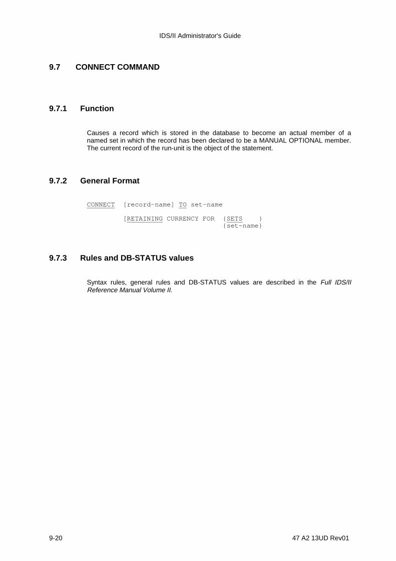
IDS/II Administrator's Guide
9-20 47 A2 13UD Rev01
9.7 CONNECT COMMAND
9.7.1 Function
Causes a record which is stored in the database to become an actual member of anamed set in which the record has been declared to be a MANUAL OPTIONAL member.The current record of the run-unit is the object of the statement.
9.7.2 General Format
CONNECT [record-name] TO set-name
[RETAINING CURRENCY FOR {SETS } {set-name}
9.7.3 Rules and DB-STATUS values
Syntax rules, general rules and DB-STATUS values are described in the Full IDS/IIReference Manual Volume II.
Interactive Data Manipulation Functions
47 A2 13UD Rev01 9-21
9.8 DISCONNECT COMMAND
9.8.1 Function
Logically removes a record from a specified set if the record is an OPTIONAL member ofthe set. The current record of the run-unit is the object of the statement.
9.8.2 General Format
DISCONNECT [record-name] FROM set-name .
9.8.3 Rules and DB-STATUS values
Syntax rules, general rules and DB-STATUS values are described in the Full IDS/IIReference Manual Volume II.

IDS/II Administrator's Guide
9-22 47 A2 13UD Rev01
9.9 ERASE COMMAND
9.9.1 Function
Removes one or more records from the database. The current record of the run-unit is theobject of the statement.
9.9.2 General Format
[{SELECTIVE} ]ERASE [record-name] [{ALL } MEMBERS ] [{PERMANENT} ]
9.9.3 Rules and DB-STATUS values
Syntax rules, general rules and DB-STATUS values are described in the Full IDS/IIReference Manual Volume II.
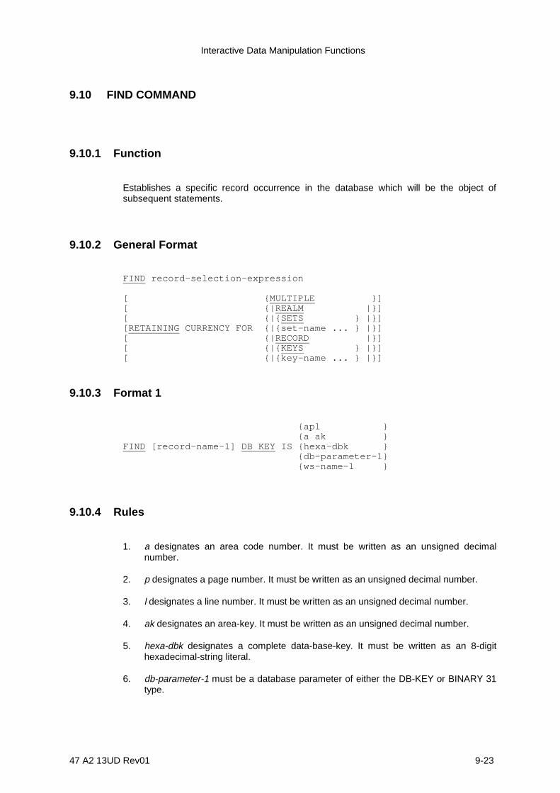
Interactive Data Manipulation Functions
47 A2 13UD Rev01 9-23
9.10 FIND COMMAND
9.10.1 Function
Establishes a specific record occurrence in the database which will be the object ofsubsequent statements.
9.10.2 General Format
FIND record-selection-expression
[ {MULTIPLE }][ {|REALM |}][ {|{SETS } |}][RETAINING CURRENCY FOR {|{set-name ... } |}][ {|RECORD |}][ {|{KEYS } |}][ {|{key-name ... } |}]
9.10.3 Format 1
{apl } {a ak }FIND [record-name-1] DB KEY IS {hexa-dbk } {db-parameter-1} {ws-name-1 }
9.10.4 Rules
1. a designates an area code number. It must be written as an unsigned decimalnumber.
2. p designates a page number. It must be written as an unsigned decimal number.
3. l designates a line number. It must be written as an unsigned decimal number.
4. ak designates an area-key. It must be written as an unsigned decimal number.
5. hexa-dbk designates a complete data-base-key. It must be written as an 8-digithexadecimal-string literal.
6. db-parameter-1 must be a database parameter of either the DB-KEY or BINARY 31type.

IDS/II Administrator's Guide
9-24 47 A2 13UD Rev01

Interactive Data Manipulation Functions
47 A2 13UD Rev01 9-25
7. ws-name-1 must be a working storage variable of either the DB-KEY or BINARY 31type.
8. For additional rules, please refer to the Full IDS/II Reference Manual Volume II.
9.10.5 Format 2
{ANY }FIND { } record-name-2 {DUPLICATE}
9.10.6 Rules
Syntax rules and general rules are described in the Full IDS/II Reference Manual VolumeII.
9.10.7 Format 3
{ANY }FIND { } [record-name-3] USING key-name-1 {DUPLICATE}
9.10.8 Rules
Syntax rules and general rules are decribed in the Full IDS/II Reference Manual Volume II.
9.10.9 Format 4
FIND [ record-name-4 ] FROM key-name-2 .
9.10.10 Rules
Syntax rules and general rules are described in the Full IDS/II Reference Manual VolumeII.

IDS/II Administrator's Guide
9-26 47 A2 13UD Rev01
9.10.11 Format 5
FIND DUPLICATE WITHIN set-name-1 USING { identifier-2 } ... .
9.10.12 Rules
1. identifier-2 ... must be defined in the RECORD Entry for the current record of the set-type referenced by set-name-1.
2. identifier-2 must include the qualification IN (OF) record-name if the same field-nameappears in several record-types of the subschema.
3. identifier-2 must be subscripted when needed. The star (*) convention may be usedin place of a subscript value to obtain all occurrences of a subscript.
4. identifier-2 may be aggregate. In this case, it is equivalent to the list of all elementaryfields it contains.
NOTE: Rules 3 and 4 are specific extensions of COBOL DML which require thatidentifier-2 be an elementary data item.
5. Please refer to the Full IDS/II Reference Manual Volume II for additional rules for thiscommand.
9.10.13 Format 6
{NEXT } {set-name-2 } {PRIOR} {realm-name-1}FIND {FIRST } [record-name-3] WITHIN {integer-1 } {LAST } {key-name-3 } {ws-name-4 }
9.10.14 Rules
1. The working storage variable referenced by ws-name-4 must contain a signedelementary integer and must have a non-null value. Data types which are permittedfor ws-name-4 are given below:
- BINARY 15 or 31,
- any DECIMAL with a null scale value.
2. Please refer to the Full IDS/II Reference Manual Volume II for additional rulesconcerning this command.
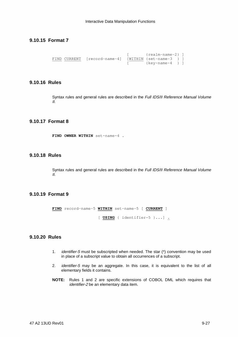
Interactive Data Manipulation Functions
47 A2 13UD Rev01 9-27
9.10.15 Format 7
[ {realm-name-2} ]FIND CURRENT [record-name-4] [WITHIN {set-name-3 } ] [ {key-name-4 } ]
9.10.16 Rules
Syntax rules and general rules are described in the Full IDS/II Reference Manual VolumeII.
9.10.17 Format 8
FIND OWNER WITHIN set-name-4 .
9.10.18 Rules
Syntax rules and general rules are described in the Full IDS/II Reference Manual VolumeII.
9.10.19 Format 9
FIND record-name-5 WITHIN set-name-5 [ CURRENT ]
[ USING { identifier-5 }...] .
9.10.20 Rules
1. identifier-5 must be subscripted when needed. The star (*) convention may be usedin place of a subscript value to obtain all occurrences of a subscript.
2. identifier-5 may be an aggregate. In this case, it is equivalent to the list of allelementary fields it contains.
NOTE: Rules 1 and 2 are specific extensions of COBOL DML which requires thatidentifier-2 be an elementary data item.

IDS/II Administrator's Guide
9-28 47 A2 13UD Rev01
3. Please refer to the Full IDS/II Reference Manual Volume II for additional rulesconcerning this command.
9.10.21 DB-STATUS Values
The DB-STATUS values are described in the Full IDS/II Reference Manual Volume II.
Interactive Data Manipulation Functions
47 A2 13UD Rev01 9-29
9.11 FINISH COMMAND
9.11.1 Function
Terminates the availability of one or more realms (areas) to subsequent DML statements.
9.11.2 General Format
FINISH [realm-name]... .
9.11.3 Rules and DB-STATUS values
Syntax rules, general rules and DB-STATUS values are described in the Full IDS/IIReference Manual Volume II.

IDS/II Administrator's Guide
9-30 47 A2 13UD Rev01
9.12 GET COMMAND
9.12.1 Function
Makes some or all fields in a database record available to the user. The object of thestatement is the current record of the run-unit.
9.12.2 General Format
Format 1 GET [record-name] [ WITH EDITION ] .
Format 2 GET {identifier-1}... [ WITH EDITION ] .
9.12.3 Syntax Rules
1. In Format 1, record-name must be the name of the current record of the run-unit.
2. In Format 2, identifier-1 ... must reference data items which are defined in theRECORD Entry for the current record of the run-unit.
3. identifier-1 must include the qualification IN (OF) record-name if the same field-nameappears in several record-types of the subschema.
4. identifier-1 must be subscripted when needed. The star (*) convention may be usedin place of a subscript value to obtain all occurrences of a subscript.
5. identifier-1 may be an aggregate. In this case, it is equivalent to the list of all theelementary fields it contains.
NOTE: Rules 4 and 5 are specific extensions of COBOL DML which require thatidentifier-1 be an elementary data item.
9.12.4 General Rules and DB-STATUS values
1. When the EDITION option is specified, the fields obtained are edited after normalcompletion of the GET statement. The edition format is the same as the one used forthe PRINT RECORD command. Please refer to the subsection entitled "DatabasePrint Functions" in Section 6 of this manual.

Interactive Data Manipulation Functions
47 A2 13UD Rev01 9-31
2. If the current record storage zone has not yet been created by a previous GET orMOVE command, a storage zone is created with the name, length and structure ofthe current record as defined in the Subschema SDDL.

IDS/II Administrator's Guide
9-32 47 A2 13UD Rev01
3. The additional rules and DB-STATUS values concerning this command aredescribed in the Full IDS/II Reference Manual Volume II.
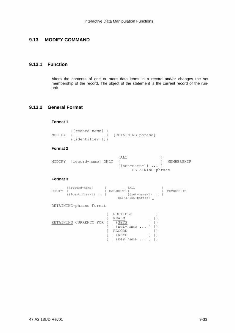
Interactive Data Manipulation Functions
47 A2 13UD Rev01 9-33
9.13 MODIFY COMMAND
9.13.1 Function
Alters the contents of one or more data items in a record and/or changes the setmembership of the record. The object of the statement is the current record of the run-unit.
9.13.2 General Format
Format 1
{[record-name] }MODIFY { } [RETAINING-phrase] {[identifier-1]}
Format 2
{ALL }MODIFY [record-name] ONLY { } MEMBERSHIP {{set-name-1} ... } RETAINING-phrase
Format 3
{[record-name] } {ALL }MODIFY { } INCLUDING { } MEMBERSHIP {{identifier-1} ... } {{set-name-1} ... } [RETAINING-phrase] .
RETAINING-phrase Format
{ MULTIPLE } { |REALM |}RETAINING CURRENCY FOR { | {SETS } |} { | {set-name ... } |} { |RECORD |} { | {KEYS } |} { | {key-name ... } |}

IDS/II Administrator's Guide
9-34 47 A2 13UD Rev01
9.13.3 Syntax Rules
1. record-name, if specified, must be the name of the current record of the run-unit.
2. identifier-1 ... must reference data items which are contained within the currentrecord of the run-unit.
3. The current record of the run-unit must be defined in the Subschema SDDL as amember of the set-types referenced by set-name ..., if those set-types exist.
4. identifier-1 must include the qualification IN (OF) record-name if the same field-nameappears in several record-types of the subschema.
5. identifier-1 must be subscripted when needed. The star (*) convention may be usedin place of a subscript value to obtain all occurrences of a subscript.
6. identifier-1 may be an aggregate. In this case, it is equivalent to the list of all theelementary fields it contains.
NOTE: Rules 5 and 6 are specific extensions of COBOL DML which require identifier-1to be an elementary data item.
9.13.4 General Rules and DB-STATUS values
The general rules and DB-STATUS values are described in the Full IDS/II ReferenceManual Volume II.
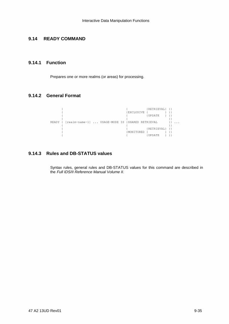
Interactive Data Manipulation Functions
47 A2 13UD Rev01 9-35
9.14 READY COMMAND
9.14.1 Function
Prepares one or more realms (or areas) for processing.
9.14.2 General Format
{ { {RETRIEVAL} }} { {EXCLUSIVE { } }} { { {UPDATE } }} { { }}READY { [realm-name-1] ... USAGE-MODE IS {SHARED RETRIEVAL }} ... { { }} { { {RETRIEVAL} }} { {MONITORED { } }} { { {UPDATE } }}
9.14.3 Rules and DB-STATUS values
Syntax rules, general rules and DB-STATUS values for this command are described inthe Full IDS/II Reference Manual Volume II.

IDS/II Administrator's Guide
9-36 47 A2 13UD Rev01
9.15 STORE COMMAND
9.15.1 Function
Causes a record to be stored in the database. This statement establishes the currentrecord of the run-unit.
9.15.2 General Format
[ {MULTIPLE |}] [ {|REALM |}] [ {| |}] [ {|{SETS } |}] [ {|{set-name ... } |}]STORE record-name [RETAINING CURRENCY FOR {| |}] [ {RECORD |}] [ {| |}] [ {|{KEYS } |}] [ {|{key-name ... } |}]
9.15.3 Rules and DB-STATUS Values
Syntax rules, general rules and DB-STATUS values are described in the Full IDS/IIReference Manual Volume II.

Interactive Data Manipulation Functions
47 A2 13UD Rev01 9-37

47 A2 13UD Rev01 10-1
10. The Format of the Database
10.1 INTRODUCTION
The IDS/II database is composed of several storage areas and index files, both of whichare UFAS INTEGRATED files.
Each IDS/II area or index file contains the following elements:
1) a UFAS file label located in the VTOC,
2) an IDS/II label located in the User Labels of the file,
3) an address space, which consists of a number of pages (NUMP). This addressspace can also be measured by units called Control Intervals or CI, which are unitsof equal size, numbered 0 to NUMP-1.
This appendix describes the structure of areas and index pages, and also describes IDS/IIlabels.

IDS/II Administrator's Guide
10-2 47 A2 13UD Rev01
10.2 OVERVIEW OF THE IDS/II PAGE STRUCTURE
10.2.1 Storage Areas
In each IDS/II area page, four contiguous zones can be distinguished. These are:
1) The page header, which contains the following types of statistics: the space currentlyused, the space occupied by inactive records, the used and unused locators, and thehighest line number in use.
2) The record space, which contains storage records and OWL records, both of whichare described below:
- Storage records are composed of a header, a pointer zone and a data zone. Theserecords are referenced by line number. They can be active or inactive (logicallydeleted). Logical deletion is a mechanism which allows the DBCS to defer thereorganization of the page until compaction becomes necessary to store a newrecord in the page
- OWL (Overflow Link) records are used in the implementation of the CALC chain.They contain a pointer zone. They are not referenced by line number.
3) The unused space, which contains space which is immediately available, without theneed for compaction to recover the space which had been occupied by deletedrecords.
4) The record locator array, which maintains the correspondence between a linenumber and a storage record. Each locator is indexed by the line number andcontains the 2-byte offset of the storage record corresponding to this line number.The 2-byte offset is relative to the end of the page header. The length of the locatorarray varies in time.
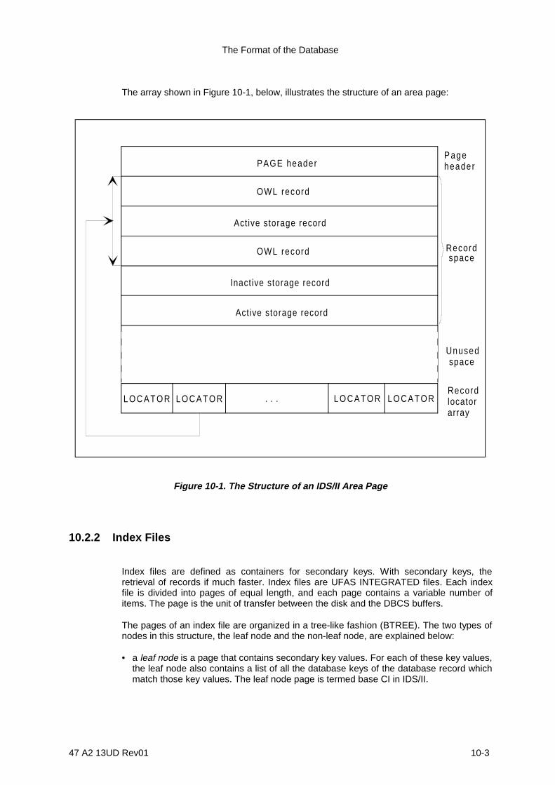
The Format of the Database
47 A2 13UD Rev01 10-3
The array shown in Figure 10-1, below, illustrates the structure of an area page:
PAGE header
OWL record
Active storage record
Inactive storage record
P ageheader
Unused space
Recordlocatorarray
L O C A T O R L O C A T O R L O C A T O R L O C A T O R
OWL record
Active storage record
. . .
Recordspace
Figure 10-1. The Structure of an IDS/II Area Page
10.2.2 Index Files
Index files are defined as containers for secondary keys. With secondary keys, theretrieval of records if much faster. Index files are UFAS INTEGRATED files. Each indexfile is divided into pages of equal length, and each page contains a variable number ofitems. The page is the unit of transfer between the disk and the DBCS buffers.
The pages of an index file are organized in a tree-like fashion (BTREE). The two types ofnodes in this structure, the leaf node and the non-leaf node, are explained below:
• a leaf node is a page that contains secondary key values. For each of these key values,the leaf node also contains a list of all the database keys of the database record whichmatch those key values. The leaf node page is termed base CI in IDS/II.

IDS/II Administrator's Guide
10-4 47 A2 13UD Rev01
• a non-leaf node is a page that contains the minimum partial key values that determinethe difference between child nodes. The non-leaf node page is termed out base CI inIDS/II. A node which has no parent is termed the ROOT node.
The following may vary between index files:
• the number of pages,• the page length,• the number of items per page.
We can distinguish four different parts in a general index page, which are explainedbelow. The parts described in 2), 3) and 4) below are managed by the Generalized IndexManager (GIM):
1) the header, which is managed by IDS/II. It contains the CI number and statistics onfree index pages. This file is always present.
2) the GIM header, which contains information on the GIM page. It has a variableprefix. The GIM header is not present for Page 0 (first page), nor for the page whichis not part of the GIM address space (free or empty page),
3) key variables for each key. These include:
- a child pointer, for non-leaf pages
- a record data-base-key, for leaf pages
4) a page locator, which is unstable because of the SORT.
The GIM is a logical index manager operating within GCOS7. It manages the functioningof the BTREE structure of the index. The GIM authorizes the manipulation of recordsunder the KEY-IDENT function.
Within this index file structure, page 0 (CI # 0) points to the first free page. It has a IDSheader, but no GIM header. Page 0 is used for the management of the empty or unusedpages. The management of free pages is accomplished by a logical grouping or chainbetween unused pages in the index.
Page 1 (CI # 1) contains the GIM ROOT.

The Format of the Database
47 A2 13UD Rev01 10-5
The array shown in Figure 10-2, below, illustrates the structure of an index page.
PAGE header ( IDS) IDS/II part
GIM page
GIM header
KEYS
L O C A T O R ...L O C A T O R L O C A T O R L O C A T O R
Figure 10-2. Structure of an IDS/II Index Page
All offsets (or locator values) of the GIM page are taken into stored at the end of the IDSheader.
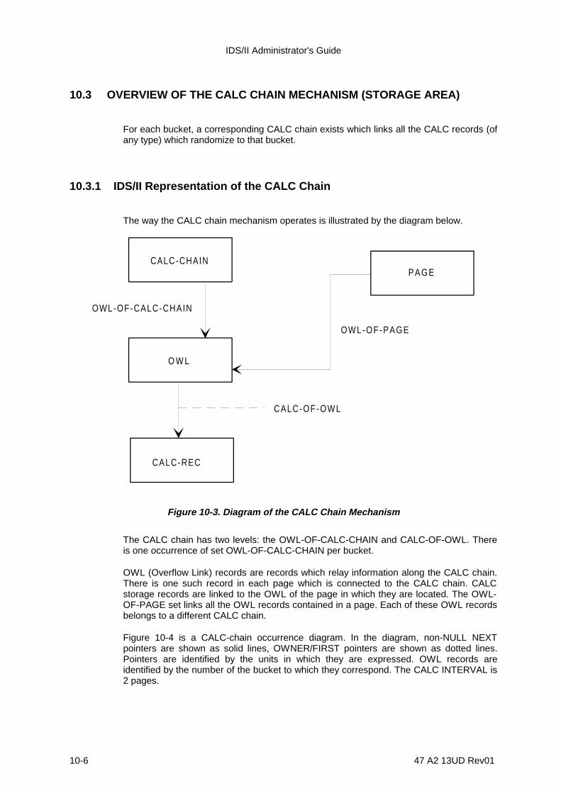
IDS/II Administrator's Guide
10-6 47 A2 13UD Rev01
10.3 OVERVIEW OF THE CALC CHAIN MECHANISM (STORAGE AREA)
For each bucket, a corresponding CALC chain exists which links all the CALC records (ofany type) which randomize to that bucket.
10.3.1 IDS/II Representation of the CALC Chain
The way the CALC chain mechanism operates is illustrated by the diagram below.
CALC-CHAIN
O W L
CALC-REC
P A G E
OWL-OF-CALC-CHAIN
OWL-OF-PAGE
CALC-OF-OWL
Figure 10-3. Diagram of the CALC Chain Mechanism
The CALC chain has two levels: the OWL-OF-CALC-CHAIN and CALC-OF-OWL. Thereis one occurrence of set OWL-OF-CALC-CHAIN per bucket.
OWL (Overflow Link) records are records which relay information along the CALC chain.There is one such record in each page which is connected to the CALC chain. CALCstorage records are linked to the OWL of the page in which they are located. The OWL-OF-PAGE set links all the OWL records contained in a page. Each of these OWL recordsbelongs to a different CALC chain.
Figure 10-4 is a CALC-chain occurrence diagram. In the diagram, non-NULL NEXTpointers are shown as solid lines, OWNER/FIRST pointers are shown as dotted lines.Pointers are identified by the units in which they are expressed. OWL records areidentified by the number of the bucket to which they correspond. The CALC INTERVAL is2 pages.

The Format of the Database
47 A2 13UD Rev01 10-7
CALC bucket 1 CALC bucket 2 CALC bucket 3
page pagepage
Pageheader
OWL (1 ) OWL (2 ) OWL (3 )OWL (1 ) OWL (1 )page
rank
linerank
OWL (1 )
l ine
OWL (1 )
OWL (2 )
l ine rank
offset offset
rank
offset
l inerank
linerank
C A L Crecord line
rank
pagerankC A L C
recordline
ranklinerank
linerank
pagerank
linerank
Pageheader
Pageheader
Pageheader
Pageheader
linerank
C A L Crecord
C A L Crecord
C A L Crecord
C A L Crecord
C A L Crecord
C A L Crecord
C A L Crecord
C A L Crecord
C A L Crecord
C A L Crecord
linerank
C A L Crecord
Figure 10-4. CALC Chain Occurrence Diagram
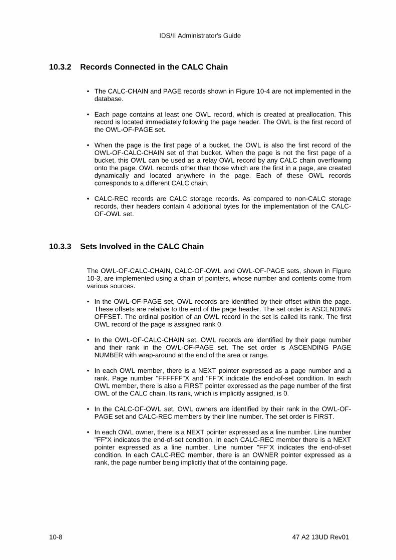
IDS/II Administrator's Guide
10-8 47 A2 13UD Rev01
10.3.2 Records Connected in the CALC Chain
• The CALC-CHAIN and PAGE records shown in Figure 10-4 are not implemented in thedatabase.
• Each page contains at least one OWL record, which is created at preallocation. Thisrecord is located immediately following the page header. The OWL is the first record ofthe OWL-OF-PAGE set.
• When the page is the first page of a bucket, the OWL is also the first record of theOWL-OF-CALC-CHAIN set of that bucket. When the page is not the first page of abucket, this OWL can be used as a relay OWL record by any CALC chain overflowingonto the page. OWL records other than those which are the first in a page, are createddynamically and located anywhere in the page. Each of these OWL recordscorresponds to a different CALC chain.
• CALC-REC records are CALC storage records. As compared to non-CALC storagerecords, their headers contain 4 additional bytes for the implementation of the CALC-OF-OWL set.
10.3.3 Sets Involved in the CALC Chain
The OWL-OF-CALC-CHAIN, CALC-OF-OWL and OWL-OF-PAGE sets, shown in Figure10-3, are implemented using a chain of pointers, whose number and contents come fromvarious sources.
• In the OWL-OF-PAGE set, OWL records are identified by their offset within the page.These offsets are relative to the end of the page header. The set order is ASCENDINGOFFSET. The ordinal position of an OWL record in the set is called its rank. The firstOWL record of the page is assigned rank 0.
• In the OWL-OF-CALC-CHAIN set, OWL records are identified by their page numberand their rank in the OWL-OF-PAGE set. The set order is ASCENDING PAGENUMBER with wrap-around at the end of the area or range.
• In each OWL member, there is a NEXT pointer expressed as a page number and arank. Page number "FFFFFF"X and "FF"X indicate the end-of-set condition. In eachOWL member, there is also a FIRST pointer expressed as the page number of the firstOWL of the CALC chain. Its rank, which is implicitly assigned, is 0.
• In the CALC-OF-OWL set, OWL owners are identified by their rank in the OWL-OF-PAGE set and CALC-REC members by their line number. The set order is FIRST.
• In each OWL owner, there is a NEXT pointer expressed as a line number. Line number"FF"X indicates the end-of-set condition. In each CALC-REC member there is a NEXTpointer expressed as a line number. Line number "FF"X indicates the end-of-setcondition. In each CALC-REC member, there is an OWNER pointer expressed as arank, the page number being implicitly that of the containing page.
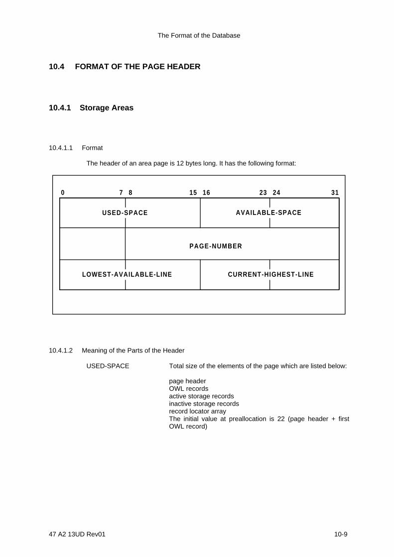
The Format of the Database
47 A2 13UD Rev01 10-9
10.4 FORMAT OF THE PAGE HEADER
10.4.1 Storage Areas
10.4.1.1 Format
The header of an area page is 12 bytes long. It has the following format:
USED-SPACE
PAGE-NUMBER
AVAILABLE-SPACE
CURRENT-HIGHEST-LINELOWEST-AVAILABLE-LINE
0 157 8 16 23 24 31
10.4.1.2 Meaning of the Parts of the Header
USED-SPACE Total size of the elements of the page which are listed below:
page headerOWL recordsactive storage recordsinactive storage recordsrecord locator arrayThe initial value at preallocation is 22 (page header + firstOWL record)

IDS/II Administrator's Guide
10-10 47 A2 13UD Rev01
AVAILABLE-SPACE Total size of the elements of the page which are listed below:
unused space inactive storage records
The relation between PAGE-SIZE and USED-SPACE isshown below:
AVAILABLE-SPACE = (PAGE-SIZE - USED-SPACE)inactive storage records
The initial value at preallocation is: PAGE-SIZE - 22.
PAGE-NUMBER Page number of the page.
Possible values are 0 to (NUMP - 1). The maximum value is(2**24)-2.
LOWEST-AVAILABLE-LINELowest line number available for assignment to a newstorage record, if no page reorganization is performed toeliminate inactive records.
When the locator array is not empty (CURRENT-HIGHEST-LINE not equal to "FFFF"X), the lowest available line iscalculated in accordance with the three possible cases,shown below:
LOWEST-AVAILABLE-LINE < CURRENT-HIGHEST-LINE.In the locator array, this is the lowest line number whoselocator contents are "FFFF"X (which does not point to anactive or inactive storage record).
LOWEST-AVAILABLE-LINE = CURRENT-HIGHEST-LINE + 1 < LINES-PER-PAGE.All locators of the array point to active or inactive records.The storage of a new record may require an increase of thearray size.
LOWEST-AVAILABLE-LINE = CURRENT-HIGHEST-LINE + 1 = LINES-PER-PAGE.The locator array has its maximum size and all the locatorspoint to active storage records.
When the locator array is empty (CURRENT-HIGHEST-LINE= "FFFF"X) LOWEST-AVAILABLE-LINE is set to 0.
CURRENT-HIGHEST-LINE When the locator array is not empty, possible values are 0 toLINES-PER-PAGE - 1 (with a maximum of 254). It is, in fact,the highest existing line number of the array. The current sizeof the locator array is: ARRAY-SIZE = (CURRENT-HIGHEST-LINE + 1) *2
The contents of the CURRENT-HIGHEST-LINE locatorcannot be "FFFF"X, because it always points to an active orinactive storage record.
When the locator array is empty, its value is "FFFF"X.

The Format of the Database
47 A2 13UD Rev01 10-11
10.5 THE FORMAT OF STORAGE RECORDS (STORAGE AREA)
10.5.1 Non-CALC Records
10.5.1.1 Format
A non-CALC record has the following format (HEADER = 5 bytes):
0 157 8 16 23 24 311 2 3 40
4
T,A RECORD - TYPE RECORD-LENGTH
EXTENDED - STATUS
SET - POINTER -ZONE
DATA - ZONE
0
STATUS :
10.5.1.2 Meaning of the Parts of the Page Header Format
STATUS
bits 0, 1 Always 0
T(RANS) bit Value 1 - TRANSIENT STATE (during the insertion orreinsertion of the record in a set or during the migration of aCALC record)
Value 0 - STABLE STATE
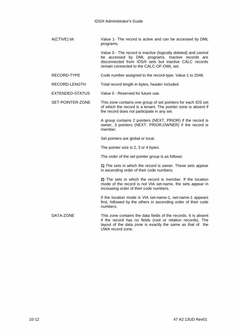
IDS/II Administrator's Guide
10-12 47 A2 13UD Rev01
A(CTIVE) bit Value 1- The record is active and can be accessed by DMLprograms.
Value 0 - The record is inactive (logically deleted) and cannotbe accessed by DML programs. Inactive records aredisconnected from IDS/II sets but inactive CALC recordsremain connected to the CALC-OF-OWL set.
RECORD-TYPE Code number assigned to the record-type. Value 1 to 2048.
RECORD-LENGTH Total record length in bytes, header included.
EXTENDED-STATUS Value 0 - Reserved for future use.
SET-POINTER-ZONE This zone contains one group of set pointers for each IDS setof which the record is a tenant. The pointer zone is absent ifthe record does not participate in any set.
A group contains 2 pointers (NEXT, PRIOR) if the record isowner, 3 pointers (NEXT, PRIOR,OWNER) if the record ismember.
Set pointers are global or local.
The pointer size is 2, 3 or 4 bytes.
The order of the set pointer group is as follows:
1) The sets in which the record is owner. These sets appearin ascending order of their code numbers.
2) The sets in which the record is member. If the locationmode of the record is not VIA set-name, the sets appear inincreasing order of their code numbers.
If the location mode is VIA set-name-1, set-name-1 appearsfirst, followed by the others in ascending order of their codenumbers.
DATA-ZONE This zone contains the data fields of the records. It is absentif the record has no fields (root or relation records). Thelayout of the data zone is exactly the same as that of theUWA record zone.
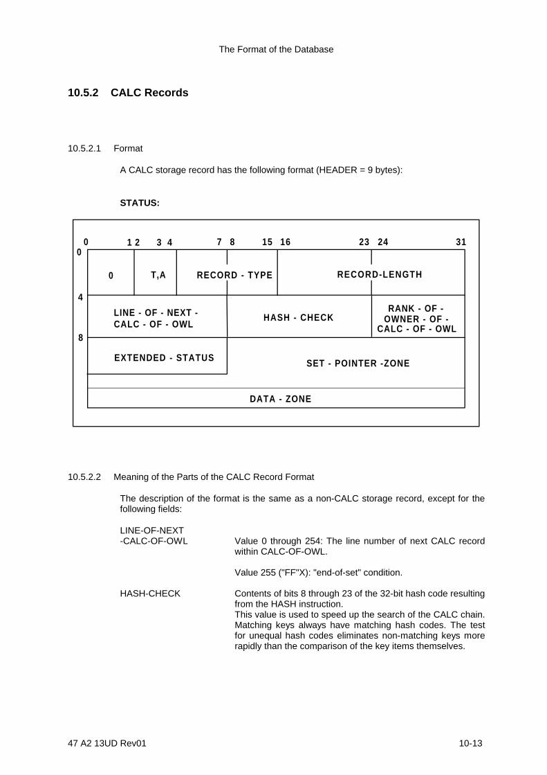
The Format of the Database
47 A2 13UD Rev01 10-13
10.5.2 CALC Records
10.5.2.1 Format
A CALC storage record has the following format (HEADER = 9 bytes):
STATUS:
0 157 8 16 23 24 311 2 3 40
4
T,A RECORD - TYPE RECORD-LENGTH
EXTENDED - STATUS SET - POINTER -ZONE
DATA - ZONE
0
8
LINE - OF - NEXT -CALC - OF - OWL
HASH - CHECKRANK - OF -
OWNER - OF -CALC - OF - OWL
10.5.2.2 Meaning of the Parts of the CALC Record Format
The description of the format is the same as a non-CALC storage record, except for thefollowing fields:
LINE-OF-NEXT-CALC-OF-OWL Value 0 through 254: The line number of next CALC record
within CALC-OF-OWL.
Value 255 ("FF"X): "end-of-set" condition.
HASH-CHECK Contents of bits 8 through 23 of the 32-bit hash code resultingfrom the HASH instruction.This value is used to speed up the search of the CALC chain.Matching keys always have matching hash codes. The testfor unequal hash codes eliminates non-matching keys morerapidly than the comparison of the key items themselves.

IDS/II Administrator's Guide
10-14 47 A2 13UD Rev01
RANK-OF-OWNER-OF-CALC-OF-OWL Value 0 through 254. Rank of owner OWL of CALC-OF-OWL
set.
Section 3 of the Full IDS/II Reference Manual Volume I and the PRINT SCHEMAcommand of the MNDD processor, which is described in Sectin 4 of the same manual,provide a detailed description of the set pointer zone and the data zone.

The Format of the Database
47 A2 13UD Rev01 10-15
10.6 FORMAT OF THE LOCATOR ARRAY (STORAGE AREA)
10.6.1 Format
The locator array is empty at preallocation time and remains in this state until the firststorage record is stored in the page. The empty condition is indicated by CURRENT-HIGHEST-LINE = "FFFF"X.
The diagram below illustrates the case when the locator array is not empty (CURRENT-HIGHEST-LINE not equal to "FFFF"X):
OFFSET
bottom of p ag e
OFFSET
OFFSET
OFFSET
OFFSET
OFFSET
-(CURRENT-HIGHEST-LINE 2 )*
-( l ine-number 2 )*

IDS/II Administrator's Guide
10-16 47 A2 13UD Rev01
10.6.2 Meaning of the Parts of the Locator Array Format
Array The array is composed of one or several 2-byte locators.
The number of locators varies in time. For further details,please see the subsection further on in this section, entitled"Dynamic Aspects of Page Management". At any given time,the number of locators of an array equals:
CURRENT-HIGHEST-LINE + 1.
Each locator corresponds to a line number. Its address,relative to the bottom of the page, is:
(line-number * 2)
OFFSET Value does not equal "FFFF"X. The contents of the locatorare the offset of the storage record corresponding to this linenumber. The offset is relative to the end of the page header.The storage record itself can be active or inactive.
Value = "FFFF"X. There is no storage record correspondingto this line number.
The OFFSET value of the locator corresponding toCURRENT-HIGHEST-LINE is always a value other than"FFFF"X.

The Format of the Database
47 A2 13UD Rev01 10-17
10.7 THE FORMAT OF THE CALC CHAIN OWL RECORD (STORAGE AREA)
10.7.1 Format
An OWL record is 10 bytes long and has the following format:
0 157 8 16 23 24 310
4
8
PAGE-OF-NEXT-OWL-OF-CALC-CHAIN RANK-OF-NEXT-OWL-OF-CALC-CHAIN
LINE-OF-NEXT-CALC-OF-OWL
OFFSET-OF-NEXT-OWL-OF-PAGE
PAGE-OF-FIRST- . . .
OWL-OF-CALC-CHAIN . . .
10.7.2 Meaning of the Parts of the CALC Chain OWL Record
PAGE-OF-NEXT-OWL-OF-CALC-CHAIN Value 0 through (2**24)-2: This value represents the page
number of the next OWL within OWL-OF-CALC-CHAIN set.
Value (2**24)-1 ("FFFFFF"X): This is an end-of-set condition.
RANK-OF-NEXT-OWL-OF-CALC-CHAIN Value 0 to 254: This value is the rank of next OWL within
OWL-OF-CALC-CHAIN set.
Value 255 ("FF"X): This is an end-of-set condition.
LINE-OF-NEXT-CALC-OF-OWL Value 0 to 254: This value is the line number of next (=first)
CALC storage record within CALC-OF-OWL.
Value 255 ("FF"X): This is an end-of-set condition.

IDS/II Administrator's Guide
10-18 47 A2 13UD Rev01
OFFSET-OF-NEXT-OWL-OF-PAGE Value 0 to 65534: This value is an offset of the next OWL
within OWL-OF-PAGE. The offset is relative to the end of thepage header.
Value 65535 ("FFFF"X): This is an end-of-set condition.
PAGE-OF-FIRST-OWL-OF-CALC-CHAIN Value (2**24)-2: This value is the page number of first OWL
within OWL-OF-CALC-CHAIN.
Value (2**24)-1 ("FFFFFF"X): This value indicates that theOWL is inactive. All other fields (with the possible exceptionof OFFSET-OF-NEXT-OWL-OF-PAGE) are in the NULLstate ("FF..."X). Thus, an inactive OWL:
has no active or inactive CALC members,is disconnected from the OWL-OF-CALC-CHAIN set,but remains connected to the OWL-OF-PAGE set.
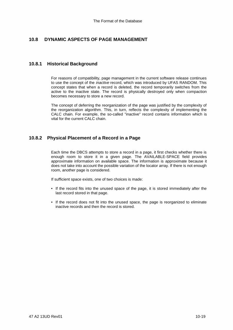
The Format of the Database
47 A2 13UD Rev01 10-19
10.8 DYNAMIC ASPECTS OF PAGE MANAGEMENT
10.8.1 Historical Background
For reasons of compatibility, page management in the current software release continuesto use the concept of the inactive record, which was introduced by UFAS RANDOM. Thisconcept states that when a record is deleted, the record temporarily switches from theactive to the inactive state. The record is physically destroyed only when compactionbecomes necessary to store a new record.
The concept of deferring the reorganization of the page was justified by the complexity ofthe reorganization algorithm. This, in turn, reflects the complexity of implementing theCALC chain. For example, the so-called "inactive" record contains information which isvital for the current CALC chain.
10.8.2 Physical Placement of a Record in a Page
Each time the DBCS attempts to store a record in a page, it first checks whether there isenough room to store it in a given page. The AVAILABLE-SPACE field providesapproximate information on available space. The information is approximate because itdoes not take into account the possible variation of the locator array. If there is not enoughroom, another page is considered.
If sufficient space exists, one of two choices is made:
• If the record fits into the unused space of the page, it is stored immediately after thelast record stored in that page.
• If the record does not fit into the unused space, the page is reorganized to eliminateinactive records and then the record is stored.

IDS/II Administrator's Guide
10-20 47 A2 13UD Rev01
10.8.3 Assignment of an Area-key to a DIRECT Storage Record (STORE)
To facilitate the storage of a record, the program attempts to assign an area-key (a pagenumber and a line number) to a record. The DBCS then trys to assign this area-key or ahigher one. Since the result of this operation depends on available space, one of thefollowing will occur:
1. The record fits into the page specified.
- If the proposed line number is exists within the current locator array and if thelocator points to an empty record space, (contents "FFFF"X), then the new record isassigned to the line specified.
- If the proposed line number exists within the current locator array and the locatorpoints to an inactive storage record, then the page reorganization is triggered andthe processing continues for the storage of the record as described above.Otherwise, the reorganization reduces the locator array size.
- If the proposed line number is represented within the current locator array and if thelocator points to an active storage record, then the record is assigned to the nexthigher line number, within the current locator array, whose locator points to anempty record space (contents "FFF"X). If no such space exists, the locator array isextended. If the locator array has reached its maximum size, the record is stored inanother page as described in paragraph 2, below.
- If the proposed line number is not represented within the current locator array, thelocator array is extended. If the record fits in the page, it is assigned the linenumber indicated. If not, the record is stored in another page as described inparagraph 2, below.
2. The record does not fit in the page specified:
The DBCS sequentially considers the next pages containing higher page numbers(with a wrap-around at the end of the range). It then attempts to store the record inthe page at the line defined by LOWEST-AVAILABLE-LINE.
10.8.4 Assignment of an Area-key to a VIA Storage Record (STORE)
1. If the set involved in the VIA phrase:
- has a set selection path composed of only one level defined BY APPLICATION
- and a set order of NEXT or PRIOR, then the DBCS attempts to place the record inthe page of the record which is pointed to by the current-of-set, at the line indicatedby LOWEST-AVAILABLE-LINE. If the record does not fit in the page, the DBCSsuccessively considers the next pages of higher page number (with wrap-around atthe end of the range).
In the case where the current-of-set points to a record of a different record-type(where the owner or member is of a different type), located in a different range, theDBCS continues processing as descibed in paragraph 2, below.

The Format of the Database
47 A2 13UD Rev01 10-21
2. If the set involved in the VIA phrase does not have the characteristics described inparagraph 1, above, the page where the record is to be stored is determined by asimilarity rule (the similarity between the range of the owner and the range of themember).
The DBCS attempts to place the record in this page at the line corresponding toLOWEST-AVAILABLE-LINE. If the record does not fit in the page, the DBCSsuccessively considers the next pages of higher page number (with wrap-around atthe end of the range).
10.8.5 Assignment of an Area-key to a CALC Storage Record (STORE)
The first page of the bucket (p-1) is determined by the randomization algorithm. The firstOWL of the OWL-OF-CALC-CHAIN set is always present. The area-key is assigned tothe CALC record in the following way:
1. If the CALC storage record fits in the page and if LOWEST-AVAILABLE-LINE <LINES-PER-PAGE, then the record is assigned the line number corresponding toLOWEST-AVAILABLE-LINE and is connected to the CALC-OF-OWL set. Thisoperation may directly follow a page reorganization.
If CALC duplicates are not allowed, the DBCS searches the OWL-OF-CALC-CHAINset and the various CALC-OF-OWL sets to perform the check. If CALC duplicatesare allowed, processing stops and the DBCS denies the STORE.
2. If the CALC storage record does not fit in page p-1 or if LOWEST-AVAILABLE-LINE= LINES-PER-PAGE, the DBCS searches the OWL-OF-CALC-CHAIN set, whichmay spread over one or more pages. These pages are not necessarily contiguous.
In each successive page containing an OWL record of the CALC chain, the DBCSattempts to store the new record as described in paragraph 1, above. If the last pageof the CALC chain (p-2) is reached without accomodating the record, the DBCSsearches the next pages with higher page numbers (with wrap-around at the end ofthe range and up to p-2). It then attempts to store both an OWL (when an inactiveone cannot be reused) and the CALC storage record.
The OWL is then connected to the OWL-OF-CALC-CHAIN and OWL-OF-PAGEsets. The CALC storage record is connected to the CALC-OF-OWL set. Thealgorithm is more complicated when a CALC chain contains records of differenttypes whose ranges overlap. The CALC chain may overflow in all ranges, but eachrecord of a given type must be located in its own range.

IDS/II Administrator's Guide
10-22 47 A2 13UD Rev01
10.8.6 Assignment of an Area-key to a CALC Storage Record(MODIFY CALC-key)
When a MODIFY function involves the modification of the CALC-key, the DBCSdetermines the bucket corresponding to the new value of the CALC-key.
1. If the new bucket is the same as the one corresponding to the old value, the DBCSchecks the DUPLICATES NOT condition, if applicable.
2. If the new bucket is not the same as the one corresponding to the old value, and ifmigration is not allowed, the DBCS disconnects the CALC record from the old CALCchain and connects it to the new CALC chain. In most cases, this connectionrequires the creation of an OWL corresponding to the new CALC chain. If there is noroom left to place the OWL in the page of the CALC record, the modification isdenied
3. If the new bucket is not the same as the one corresponding to the old value, and ifmigration is allowed, the DBCS preforms the same operation as if it were storing theCALC record. When the new data-base-key is determined, all the pointers related tothe old record are modified to point to the new record and the old record is madeinactive.
10.8.7 Deletion of OWL Records (Page Reorganization, FINDANY/DUPLICATE)
1. When a FIND ANY/DUPLICATE function is executed and the area is open in updatemode:
- the OWL records retrieved during the search of the OWL-OF-CALC-CHAIN set aredisconnected from the OWL-OF-CALC-CHAIN,
- and the owners of an empty CALC-OF-OWL set are also disconnected from theOWL-OF-CALC-CHAIN set.
However, these OWL records and owners remain connected to the OWL-OF-PAGEset.
2. When a page is reorganized (by the STORE command, or with the MODIFYcommand with migration), the OWL records it contains are physically deleted only inthe following conditions:
- if they are disconnected from the OWL-OF-CALC-CHAIN set,
- and if they occupy the last rank (except 0) of the OWL-OF-PAGE set.
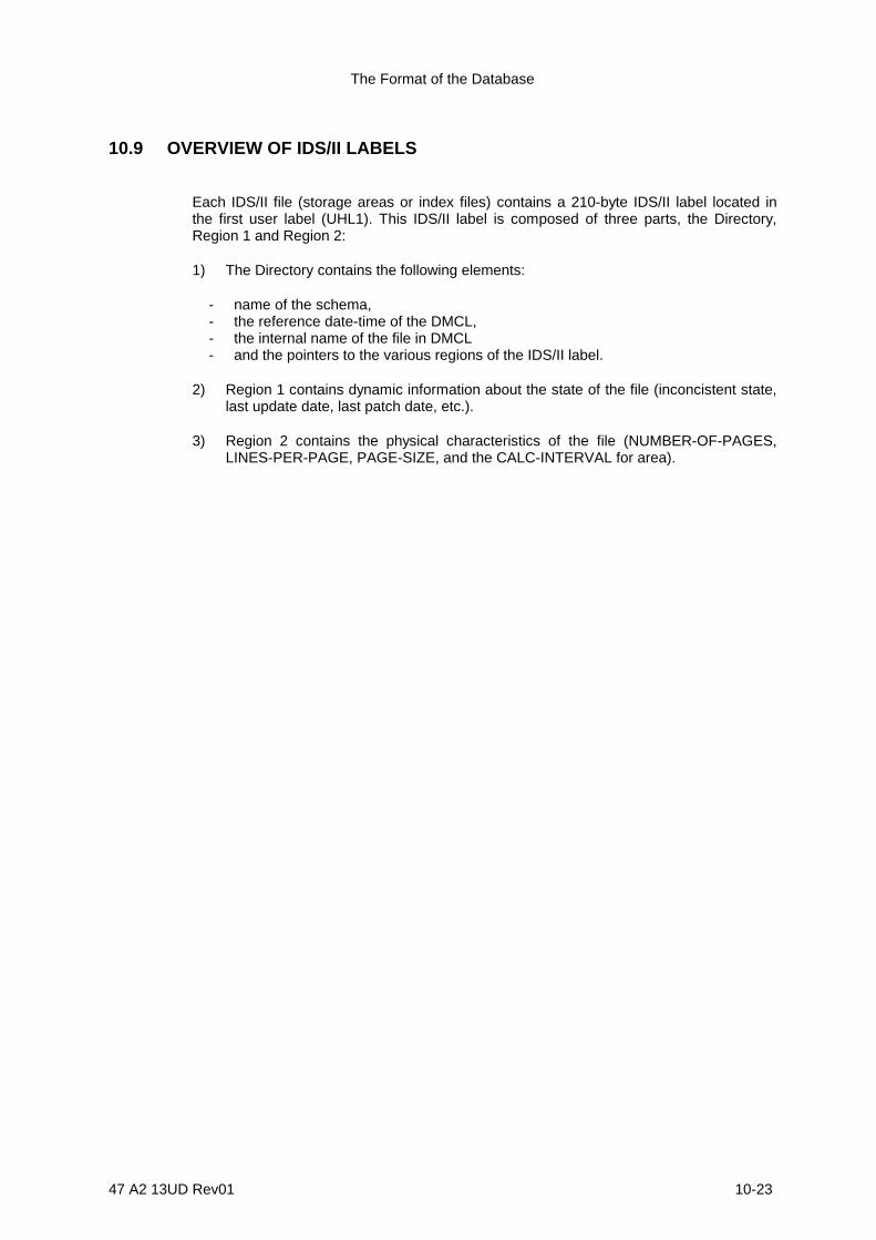
The Format of the Database
47 A2 13UD Rev01 10-23
10.9 OVERVIEW OF IDS/II LABELS
Each IDS/II file (storage areas or index files) contains a 210-byte IDS/II label located inthe first user label (UHL1). This IDS/II label is composed of three parts, the Directory,Region 1 and Region 2:
1) The Directory contains the following elements:
- name of the schema,- the reference date-time of the DMCL,- the internal name of the file in DMCL- and the pointers to the various regions of the IDS/II label.
2) Region 1 contains dynamic information about the state of the file (inconcistent state,last update date, last patch date, etc.).
3) Region 2 contains the physical characteristics of the file (NUMBER-OF-PAGES,LINES-PER-PAGE, PAGE-SIZE, and the CALC-INTERVAL for area).

IDS/II Administrator's Guide
10-24 47 A2 13UD Rev01
The general structure of the IDS/II label is illustrated in the following array:
4 bytes
"UHL1" HEADER
DIRECTORY
210 bytes
94 bytes
REGION 1
REGION 2
20 bytes
42 bytes
96 bytes
Figure 10-5. Structure of the IDS/II Label

The Format of the Database
47 A2 13UD Rev01 10-25
10.9.1 THE FORMAT OF THE DIRECTORY IN THE IDS/II LABEL
10.9.1.1 Format
The directory is 96 bytes long. It has the following format:
TAG FORMAT
SCHEMA-NAME
DMCL-DATE
DMCL-TIME
TOTAL-SIZE
REGION-1-SIZE REGION-1-OFFSET
REGION-2-SIZE
0
0
0
0
0
0
0
0 15 16 23 24 31
4
40
44
76
80
84
88
92
REGION-2-OFFSET
Internal Name of AREA or INDEX fi le
(30 characters )
(30 characters )
87
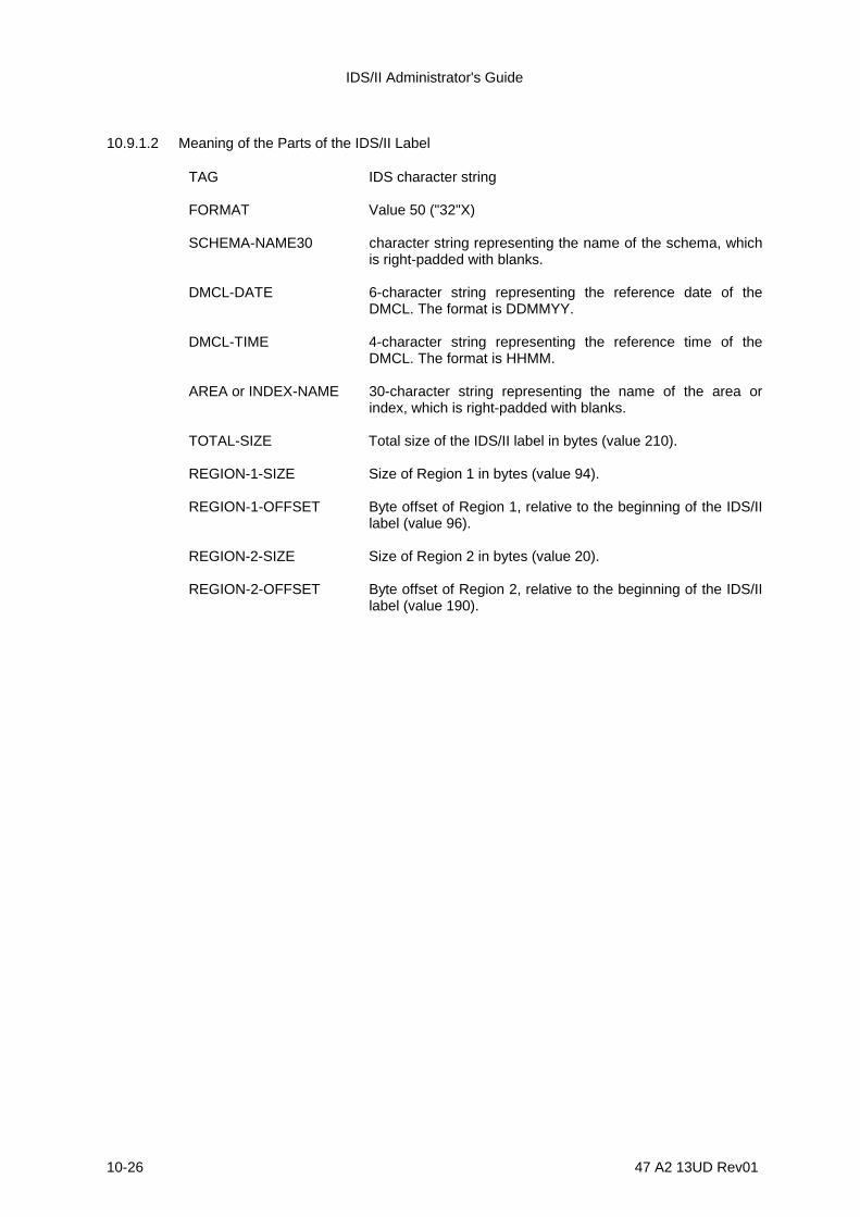
IDS/II Administrator's Guide
10-26 47 A2 13UD Rev01
10.9.1.2 Meaning of the Parts of the IDS/II Label
TAG IDS character string
FORMAT Value 50 ("32"X)
SCHEMA-NAME30 character string representing the name of the schema, whichis right-padded with blanks.
DMCL-DATE 6-character string representing the reference date of theDMCL. The format is DDMMYY.
DMCL-TIME 4-character string representing the reference time of theDMCL. The format is HHMM.
AREA or INDEX-NAME 30-character string representing the name of the area orindex, which is right-padded with blanks.
TOTAL-SIZE Total size of the IDS/II label in bytes (value 210).
REGION-1-SIZE Size of Region 1 in bytes (value 94).
REGION-1-OFFSET Byte offset of Region 1, relative to the beginning of the IDS/IIlabel (value 96).
REGION-2-SIZE Size of Region 2 in bytes (value 20).
REGION-2-OFFSET Byte offset of Region 2, relative to the beginning of the IDS/IIlabel (value 190).
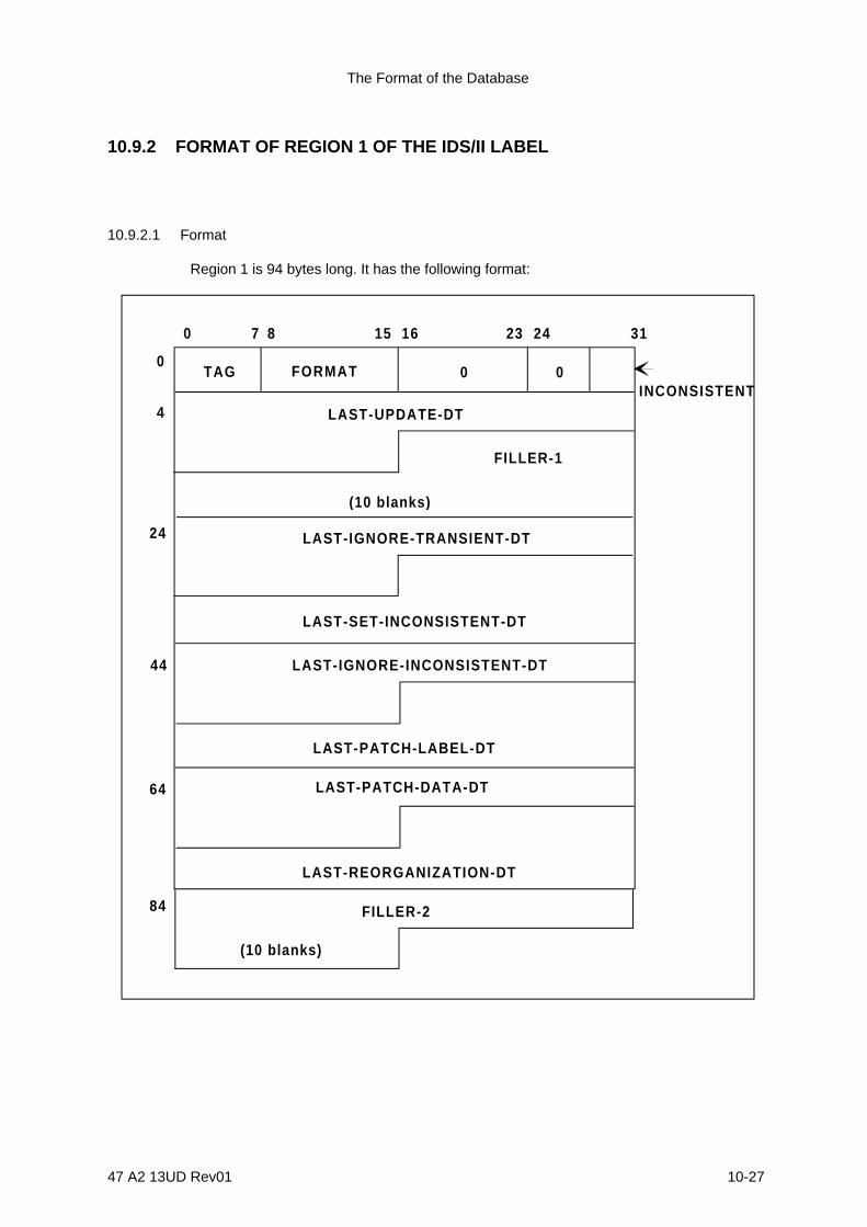
The Format of the Database
47 A2 13UD Rev01 10-27
10.9.2 FORMAT OF REGION 1 OF THE IDS/II LABEL
10.9.2.1 Format
Region 1 is 94 bytes long. It has the following format:
TAG FORMAT0
0 15 16 23 24 31
4
0 0
LAST-UPDATE-DT
FILLER-1
(10 blanks )
LAST-IGNORE-TRANSIENT-DT
LAST-IGNORE-INCONSISTENT-DT
LAST-SET-INCONSISTENT-DT
LAST-PATCH-LABEL-DT
LAST-PATCH-DATA-DT
LAST-REORGANIZATION-DT
FILLER-2
(10 blanks )
84
64
44
24
INCONSISTENT
87

IDS/II Administrator's Guide
10-28 47 A2 13UD Rev01
10.9.2.2 Meaning of the Parts of Region 1
TAG Character "1"
FORMAT Value 50 ("32"X)
INCONSISTENT Value 0: he area or index is considered structurally consistentfrom the IDS/II point of view.
Value 1: The area or index is considered locally inconsistent.
LAS-UPDATE-DT 10-character string which indicates the data-time of the lastREADY in UPDAE mode.
The format is DDMMYYHHMM.
LAS-IGNORE-TRANSIENT-DT 10-character string which indicates the date-time of the last
time that the RANSIEN state was ignored. he format isDDMMYYHHMM.
LAST-SET-INCONSISTENT-DT 10-character string which indicates the date-time of the last
time that the DBCS discovered a database inconcistency.The format is DDMMHHMM.
LAST-IGNORE-INCONSISTENT-DT 10-character string which indicates the date-time of the last
time that the INCONSISTENT state was ignored. The formatis DDMMYYHHMM.
LAST-PATCH-LABEL-DT 10-character string which indicates the data-time of the lasttime that a DBUILY PATCH LABEL AREA or PATCH LABELINDEX command was executed. The format isDDMMYYHHMM.
LAST-PATCH-DATA-DT 10-character string which indicates the date-time of the lasttime that DBUTILITY PATCH PAGE or PATCH RECORDcommand was executed. he format is DDMMYYHHMM.
LAST-REORGANIZATION-DT 10-character string which indicates the date-time of the last
time that database reorganization was performed.The formatis DDMMYYHHMM.
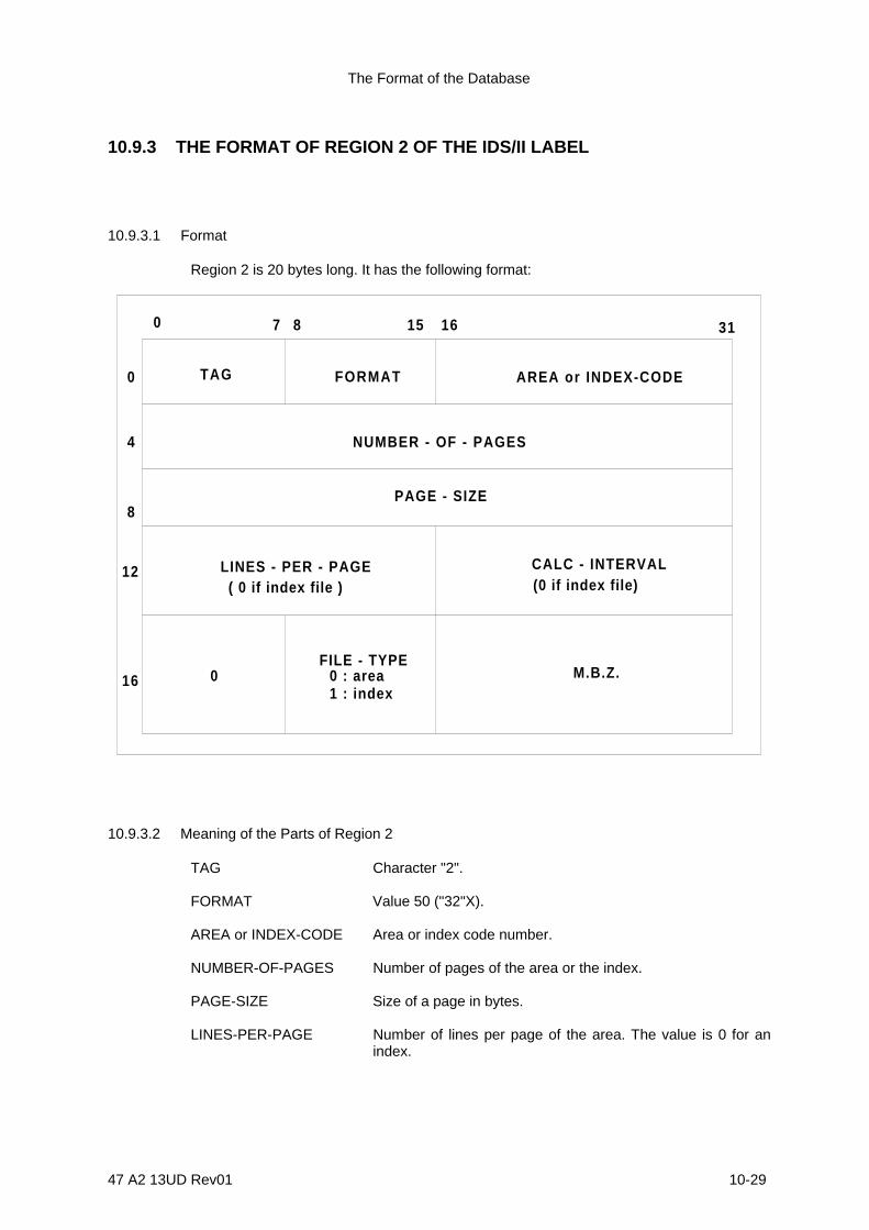
The Format of the Database
47 A2 13UD Rev01 10-29
10.9.3 THE FORMAT OF REGION 2 OF THE IDS/II LABEL
10.9.3.1 Format
Region 2 is 20 bytes long. It has the following format:
0 7 8 15 16 31
TAG FORMAT AREA or INDEX-CODE0
4
8
NUMBER - OF - PAGES
PAGE - SIZE
12 LINES - PER - PAGE( 0 if index file )
CALC - INTERVAL
FILE - TYPE0 : area1 : index
M.B.Z.16 0
(0 if index file )
10.9.3.2 Meaning of the Parts of Region 2
TAG Character "2".
FORMAT Value 50 ("32"X).
AREA or INDEX-CODE Area or index code number.
NUMBER-OF-PAGES Number of pages of the area or the index.
PAGE-SIZE Size of a page in bytes.
LINES-PER-PAGE Number of lines per page of the area. The value is 0 for anindex.

IDS/II Administrator's Guide
10-30 47 A2 13UD Rev01
CALC-INTERVAL CALC interval in pages for an area. The value is 0 for anindex.
FILE-TYPE Value 0: for an area file.
Value 1: for an index file.